

NetThings Energy Manager, NT01:00:00 Installation Manual
A UNIQUE real-time energy monitoring system for
all utility types including heat and water that is worth
two code credits under the Code for Sustainable Homes.
Installation is fast and simple
Measurement units and smart displays are
tted over standard double electrical boxes.
Simple push-t spring connectors
internally for ease of cable installation.
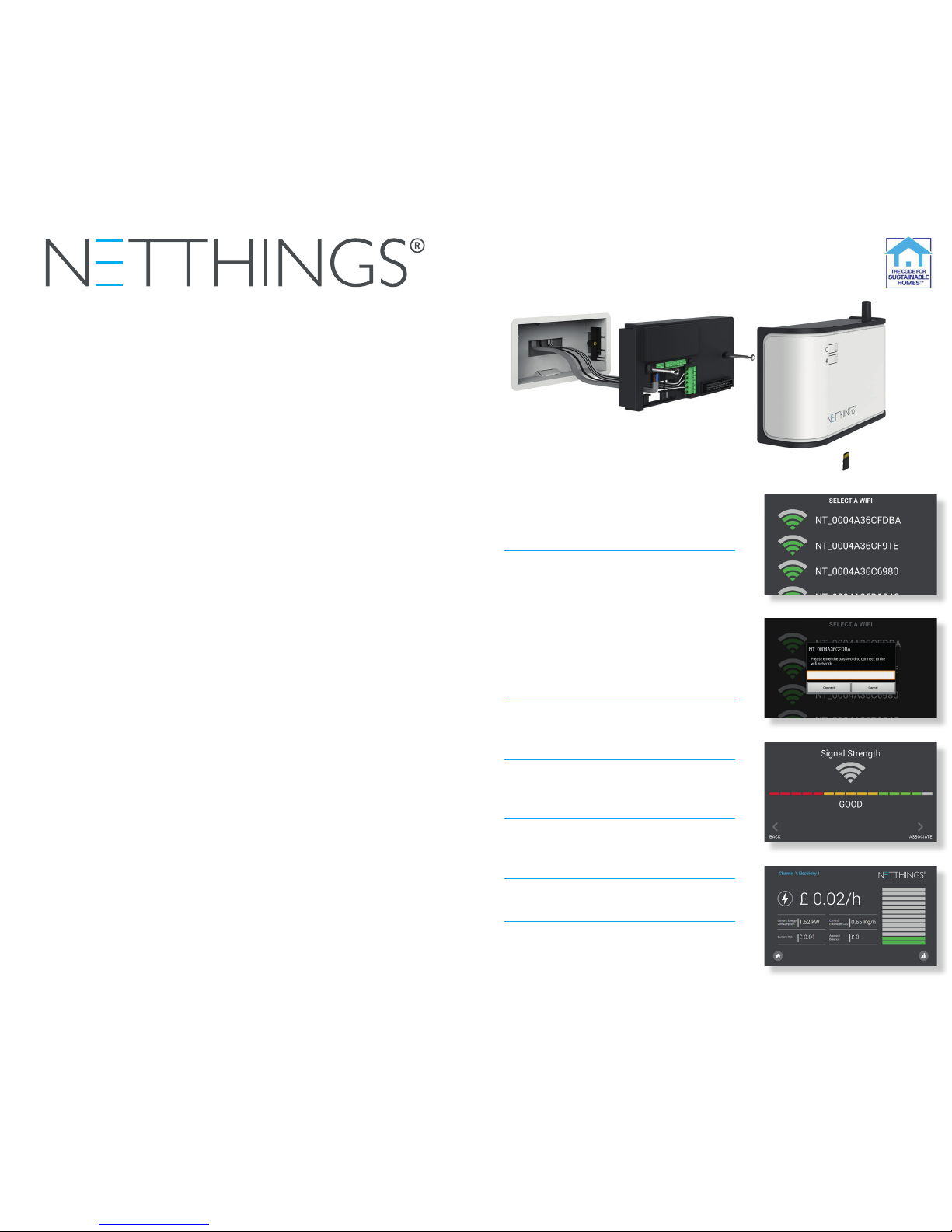
HOW TO PAIR THE WIFI SMART
DISPLAY TO NETTHINGS
MEASUREMENT UNIT
AND GET STARTED
1. Power up the Energy Manager and
wait till the LEDs start flashing.
2. Power up the display and use a
paperclip inserted into the top of
the frame to turn on the display.
3. Select the correct Energy Manager
WiFi from the list displayed and
pair the display to this.
4. The MAC address and password
to pair devices is supplied in the
packaging.
5. Check signal strength and press
‘associate’.
6. Display will now show the energy
screens.
EASY TO INSTALL
Removable microSD
card to upgrade
software and export
data (not supplied).
Energy Manager for the home is a sophisticated but low-cost, mains
powered integrated energy, heat and water monitoring package that
saves money by helping you reduce your energy consumption.
It is easy to install in new homes or retrot into existing properties.
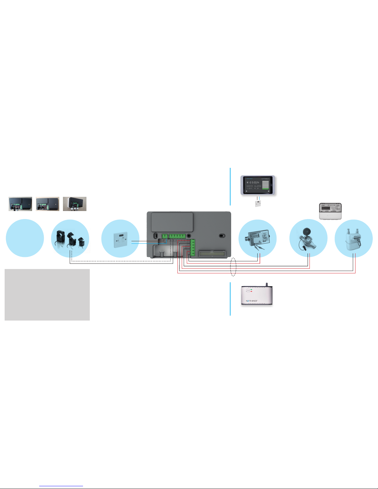
The heart of the system is the NetThings measurement unit,
which is normally installed close to the home consumer unit, with
a mains power supply. The Unit can be wired with up to 6 sensors
for in-coming mains electricity, gas and water supplies or to monitor
the electrical output from solar PV systems, or the heat /cooling
output from solar thermal systems or district heating schemes.
CT (current transducer) clips are used for the electricity supplies,
pulse connectors for the gas, water meters and heat meters,
which are all wired in directly to NetThings.
On-going energy consumption and costs are stored continually
within the NetThings unit and can also be downloaded to a
removable microSD card (not supplied). Built-in WiFi allows Energy
Manager to communicate real-time monetary values of your energy
use directly with a local display in the home without requiring an
existing broadband internet connection. During the summer of 2015
NetThings will be launching their cloud service, where data will be
viewable from anywhere in the world via an internet browser.
The NetThings monitor and 5” local display screen qualify
for 2 credits under the Code for Sustainable Homes.
ENERGY MANAGER
SPECIFICATIONS &
INSTALLATION GUIDE
EFFORTLESS CONTROL
4
3
5
6
8 STEPS TO A SUCCESSFUL INSTALLATION
1. Please choose a suitable location for the display and Energy Manager.*
2. Ensure that a 13A power supply is available at these chosen locations.
3. If your chosen location for the Energy Manager is not adjacent to the services you
require monitored then run cabling between these during your rst x installation.
4. Fix Energy Manager and display in their nal position and make connections.
5. Make connections to the service you require to be monitored.**
6. Pair the display to the Energy manager.
7. Use energy on systems that you have connected to and check that this registers on your display.
8. Leave information with the end user for them to gain maximum usage of this product
.
*As this product communicates with WiFi frequencies the signal from the Energy Manager should easily reach the display
within modern houses but solid walls and obstructions can affect this. If you are in doubt about the effectiveness of the
signal strength please check before installation. ** Additional equipment may be needed to connect to other manufacturer’s
products. Please contact NetThings if in doubt.
IMPORTANT ALL WIRING SHOULD BE CARRIED
OUT BY A COMPETENT INSTALLER OR ELECTRICIAN.
QUALIFIED TO WORK WITH MAINS ELECTRICITY AND
BE IN ACCORDANCE WITH IEE & BUILDING REGULATIONS
AND IN SOME CASES, NOTIFIABLE TO BUILDING CONTROL.
DO NOT CARRY OUT THIS INSTALLATION IF UNDER
THE INFLUENCE OF ALCOHOL OR DRUGS.
CAN CONNECT UP TO 3 PULSE O/P UTILITY METERS.
PULSE INPUTS ARE AT LOW VOLTAGE.
If you have any questions about installing
this product please contact NetThings or
visit www.netthings.co.uk/support
WATER METERS
Water meters need to be specied as pulse enabled. Polarity
of pulse is not critical as pulses are mechanically generated.
GAS METERS
Ensure gas meters are pulse enabled and tted with the
appropriate pulse block. As there are several different types
please ensure that the correct pulse block is ordered.
If unsure check our support website for further information.
www.netthings.co.uk/support
ELECTRIC METERS
If monitoring solar PV systems then t an import export
meter and connect Energy Manager via pulse cables. Polarity
of connection is important here as it is an electronically
generated pulse. Observe pulse polarity when connecting.
HEAT METERS
Heat meters require to be pulse enabled and with a low
pulse setting i.e. 1 pulse per watt hour of energy.
Back Plate: 154mm x 86mm
Display screen is tted to a double recessed box.
Tablet in mount: 173mm x 99mm x 14mm
Fused 3A Spur
Cable specication: Beldon 9501 or equivalent.
WARNING - Electric Shock Hazard! Make all cable connections to device
before powering up the unit. Always power-down before disconnecting cables.
Direct Mounting
(Cable restraints must be used)
Recessed Box Surface Box
Fused
3A Spur
Heat Meters Gas MetersWater MetersCan Connect
up to 3 x CTs
NETTHINGS MEASUREMENT
UNIT BACKPLATE
upto 6 channels I/P
plus power supply
CURRENT
TRANSFORMERS
Three sizes are available
most commonly supplied is
CT16. If monitoring 3 phase
connect one CT to each phase
and connect to terminals
1-2, 3-4 & 5-6. CTs come with
cable attached - polarity
isn’t important.
ELECTRICIAN
PLEASE READ THESE INSTRUCTIONS IMMEDIATELY ON
RECEIPT OF THIS PRODUCT AND CARRY OUT
STEPS 1 TO 3 AS SOON AS POSSIBLE.
MOUNTING OPTIONS
The Energy Manager can be tted in either of the following options:
Electric Meters
Outer cover clips over the backplate.
 Loading...