

NetThings EMK-200, EMK-001 Installation Manual
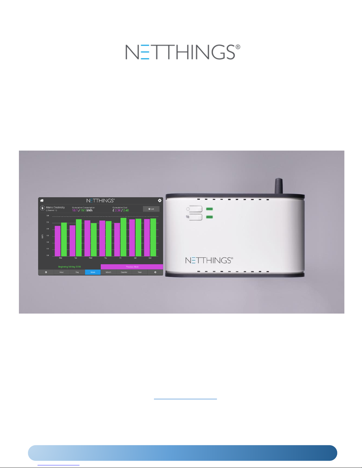
ENERGY MANAGER
INSTALLATION & USER GUIDE
NetThings Ltd
14 New Mart Road
Edinburgh
EH14 1RL
UK
E: info@netthings.co.uk
T: +44 (0) 131 331 5445
Document 200SM075 Version 2.0

2
INSTALLATION OVERVIEW
3
INSTALLATION CONNECTIONS
4
COMMISSIONING THE ENERGY MANAGER
5
USING THE ENERGY MANAGER
8
ADDITIONAL INFORMATION
10
SPECIFICATION
12
APPENDIX 1
– M-BUS INSTALLATION
13
APPENDIX 2
– EVINOX INTEGRATION
15
3
INSTALLATION OVERVIEW
8 STEPS TO A SUCCESSFUL INSTALLATION
1
Choose suitable locations for the Energy Manager and Display, ensuring that the data ports on the
bottom of the Energy Manager are easily accessible for the end user. This product uses WiFi
technology to link the controller to the display. The signal from the Energy Manager should reach
the Display within modern houses but solid walls and obstructions can affect this. To ensure best
performance the distance between the Display and Energy Manager should not exceed 5
metres. If you are in doubt about the effectiveness of the signal strength please check before
installation.
2
Ensure a mains power supply is available at these locations.
If your chosen location for the Energy Manager is not adjacent to the services you require to be
monitored then run cabling between these positions during your first fix installation.
3
Fix the Energy Manager and Display in their final positions and make power supply connections.
Make connections to the service you require to be monitored. Note: Additional equipment may
be required to connect to other manufacturer’s products. Please contact NetThings if in doubt.
Pair the Display to the Energy manager, complete the channel setup, and remove the yellow
commissioning warning banner.
Use energy on systems that you have connected to and check that this registers on your display.
Leave information with the end user for them to gain maximum usage of this product.
4
5
6
7
8
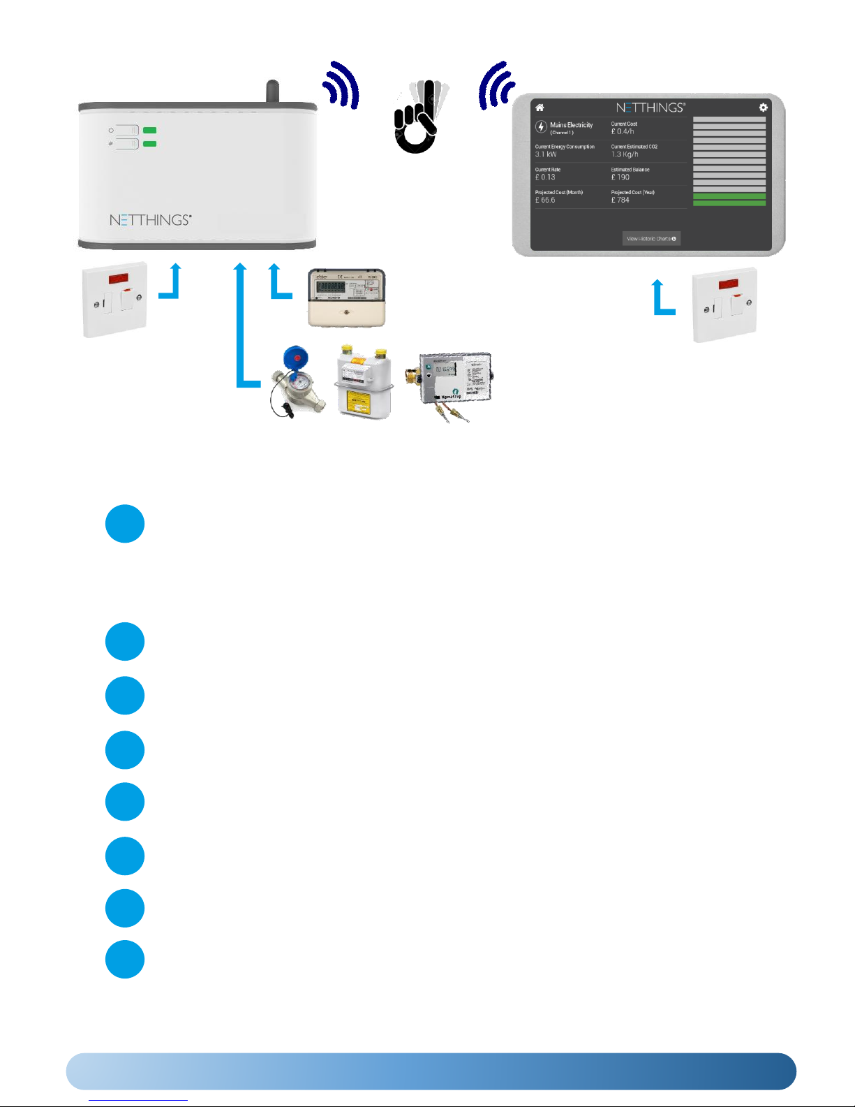
No cables are required
between the controller and
the display. WiFi technology is
used to link the controller to
the display.
Electricity via current
transducer (CT) or pulse
connection
Gas, Water & Heating
via Pulse and M-Bus
(where fitted)
ENERGY MANAGER CONTROLLER
DISPLAY

4
Please install current
transducers in correct
orientation as detailed
on the device.
Note the CT size details for set up later.
CURRENT FLOW
The supply should be a
3A Switched Fused
Spur, marked to show
its purpose and easily
accessible.
When connecting current
transducers:
• Install single phase
monitoring to channel one.
• For 3 phase CT follow L1,
L2, L3 normal logical
connection.
Channel 3 CT
Connections
Channel 2 CT
Connections
Channel 1 CT
Connections
Channel 4
PULSE ONLY
Channel 5
PULSE ONLY
Channel 6
PULSE &
M-Bus
When connecting
PULSE cables, start
connections at
channel 4 first
before connecting
to channel 5 & 6.
Channel 6 is used for both PULSE &
M-Bus (where fitted) inputs.
PLEASE NOTE:
• The M-Bus functionality is enabled
via the M-Bus menu in the
Configuration Setup. If enabled,
ensure no pulse connections are
made on Channel 6
• M-Bus wiring has no polarity
• Unsupported meters that are
discovered on the scan may need
further setup to define the correct
M-Bus records to report on.
INSTALLATION TIPS
• Cables between Netthings
controller and pulse enabled
meters should be Belden 9501
or equivalent.
• Ensure gas meters that are
pulse enabled are fitted with
the appropriate pulse block.
As there are several different
types please ensure that the
correct pulse block is ordered.
• The Display and the Controller
need to be within 5m of each
other otherwise the WIFI
communication may be
unreliable.
The Energy Manager Controller is typically
mounted in a recessed 2-gang pattress box,
however should the Controller be mounted in a
surface box or directly to the wall, glands and
cable restraints should be used as required. It is
powered via a 3A Switched Fused Spur, marked
to show its purpose and easily accessible.
(Example of a Recessed Box Installation)
The Energy Manager Display should be mounted in a recessed 2gang pattress box and powered via a 3A Switched Fused Spur,
marked to show its purpose and easily accessible. The power and
reset button for the display can be accessed via the small hole on
the top left of the display mount (5” Display) or the right hand side
of the display mount (7” Display) with the supplied Allen key.
If you have any questions about installing this product please contact NetThings or visit www.netthings.co.uk
SUPPORTED M-Bus Meter
Manufacturers
The following manufacturers of M-Bus
meters are currently supported for use
with Energy Manager.
Diehl, GWF, Kamstrup, Sontex, Danfoss.
Please contact Netthings or visit
www.netthings.co.uk for further
information
RESET 5”
INSTALLATION CONNECTIONS
RESET
7”
5
COMMISSIONING THE ENERGY MANAGER
Once the Controller and Display have been correctly installed, power up both and wait for the controller to
broadcast its own Wi-Fi signal.
The display can be turned on using the Allen key provided, inserted into the small hole of the frame if it hasn’t
started upon application of power.
POWER UP
WIFI CONNECTION (WPS)
WPS is the easiest method to connect the Controller
& Display
• Press and hold the # button on the energy
manager for 3 seconds until its LED turns solid
Green and release.
• Press the WPS symbol on the screen of the display.
• The display will automatically connect to the
controller and show the home page.
The Controller and Display can also be paired using the password supplied with the Controller.
• The SSID and password to pair Controller and Display can found within the packaging and also on a label on the
top of the controller.
• Select the correct Energy Manager WIFI from the list displayed to pair the display. The SSID will start with ‘NT_’.
• Enter the password for the chosen Controller.
• Check the signal strength and press ASSOCIATE.
WIFI CONNECTION (Alternative Method)
The SSID (wireless connection name) for the Controller will be shown on the Display when the Controller has
successfully started. The list can be refreshed by swiping downwards on the screen.
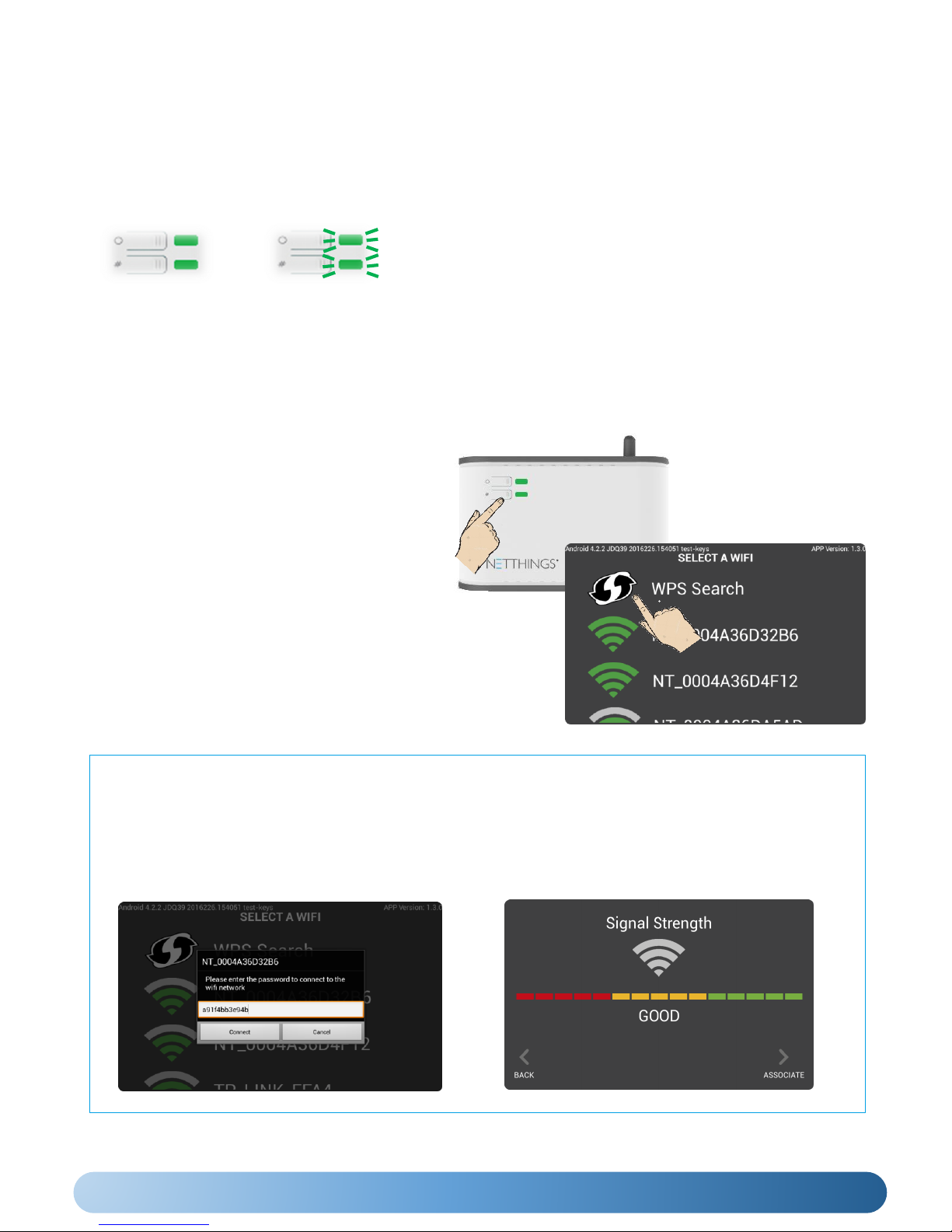
The Controller’s LEDs will light continuously green whilst it is
starting up, for approximately 1-2 minutes. Once the LEDs
start to flash green, the controller is ready to connect
wirelessly to the display.
SOLID
Controller Starting
FLASHING
Ready to Connect
PLEASE CONTINUE AND COMPLETE THE CONFIGURATION OF THE METERING CONNECTIONS
6
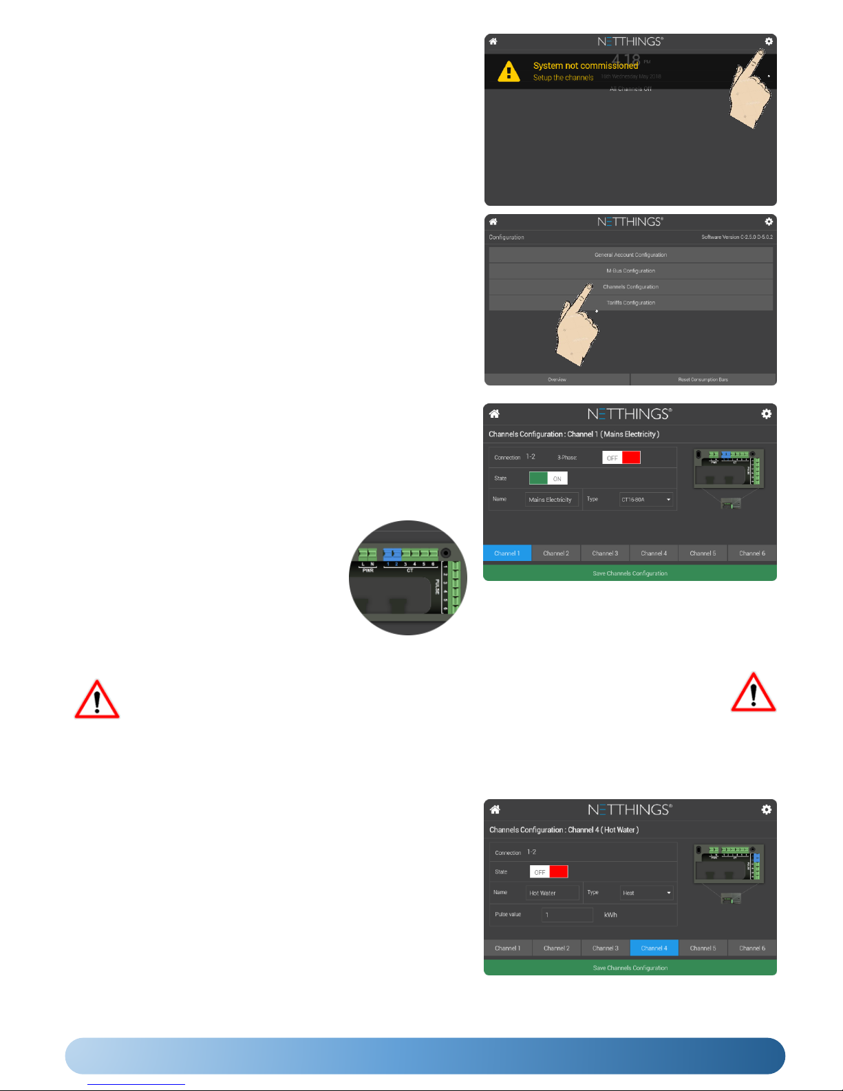
• Check that all connected channels are enable by turning the State
to ON and that the correct CT types are selected.
• If monitoring a 3-phase supply then turn 3-phase ON in Channel 1.
• The Name field can be used for the installer to identify what is
connected.
SETTING UP ELECTRICITY CHANNELS
• The Type field is used to select the CT that has
been used in the installation.
• The terminal blocks shown as blue indicate
the connection pair that correspond to the
channel.
• Press Save Channel Configuration before
exiting and use setup button in the top right
hand corner to return to the Configuration
Menu.
(Typical example of a Single Phase Electricity Configuration)
• Check that all connected channels are enable by turning the State
to ON.
• The Type field has a drop down menu and this will allow you to
choose the correct utility type that is connected to your energy
manager.
• The Name field can be used for the installer to identify what is
connected.
• The Pulse Value field should be set to the corresponding value of
the energy source that you are connecting to. This value may be
indicated on the connected energy source.
• Press Save Channel Configuration before exiting and use setup
button in the top right hand corner to return to the Configuration
Menu.
SETTING UP PULSE INPUT CHANNELS
CONFIGURATION
Following a successful WIFI connection between the Controller and
the Display, the Energy Manger should now be configured to
enable the energy sources that are connected to the meter.
To Setup the system, press the setup icon in the top right
hand corner of the screen.
Press Channels Configuration to start configuration of the
channels.
(Please Note: M-Bus options are only visible and enabled on MBus capable hardware. 3rdparty integration menus are only
visible when appropriate hardware is connected.)
If intending to use M-Bus functionality or any 3rdparty integration, please follow the
instructions in appropriate Appendix first, before returning to the complete the pulse
setup, and the remainder of the commissioning process.
 Loading...