


Operating instructions for
Netter Electric External Vibrators
series NEA/NEG/NEG S/NES
Sept. 2020
No. 1929E
Page 1/35
These operating instructions apply to:
Series NEA
Series NEG
Series NEG S
Series NES

2
Document no.
1929E
Version no.
2
Date of issue
Sept. 2020
Scope of
delivery
Designation
Version of
document
Contents
1 General information 3
2 Safety 6
3 Technical data 11
4 Design and function 13
5 Transport and storage 14
6 Installation 15
7 Start-up and operation 19
8 Maintenance and servicing 26
9 Troubleshooting 31
10 Spare parts and accessories 33
11 Disposal 35
Please refer to the delivery note for the scope of delivery.
Check the packaging for possible transport damage. In the event of
damage to the packaging, check the contents for completeness and
possible damage. Inform the carrier in the case of damage.
The Electric External Vibrators of the series NEA, NEG, NEG S and
NES are hereafter referred to as "NEA/NEG".

General information
3
Use and
storage
Target group
Copyright
Limitation of
liability
Directives /
standards
observed
1 General information
Before installing the NEA/NEG read these instructions carefully. It is the
basis for any action when dealing with the NEA/NEG, and may be used for
training purposes. The instructions should be subsequently stored at the
operation site.
The target group for these instructions is technical staff, who have basic
knowledge of mechanics, electrics and explosion protection.
Only complying technical staff may work on the NEA/NEG.
The NEA/NEG may only be installed, put into operation, maintained, trou-
bleshot and disassembled by persons authorised by the operator.
This documentation is protected by copyright.
Netter
Vibration reserves all rights such as translations, reprinting and re-
production of the instructions, as well as parts thereof.
All technical information, data and instructions for installation, operation
and maintenance in these instructions are based on the latest information
available at the time of printing and take our past experience to the best of
our knowledge into account.
No claims can be derived from the information, illustrations and descriptions in these operating instructions.
The manufacturer does not assume liability for damages resulting from:
failure to observe the instructions,
improper use,
unauthorised repairs,
technical modifications,
use of non-permissible spare parts.
Translations are made to the best of our knowledge.
Netter
Vibration does not assume liability for translation errors, even if the
translation was made by us or on our behalf. Only the original German text
remains binding.
The Electric External Vibrators of the series NEA, NEG, NEG S and NES
comply with the EC Machinery Directive 2006/42/EC, the electromagnetic
compatibility directive 2014/30/EU and the low voltage directive
2014/35/EU.
In particular the standards EN ISO 12100, EN 60529 and DIN EN 60034-1
has been observed.
All Electric External Vibrators of the series NEA, NEG, NEG S and
NES, labelled with the Ex-Symbol on the type plate, comply with the ATEX
Directive 2014/34 EU for equipment group II.
NEA/NEG of housing size 50 and 60 are suitable for use in potentially explosive areas of the category 3D in the zone 22.

General information
4
DANGER
indicates an immediate danger.
Disregard of this notice will result in death or severe person-
al injuries.
WARNING
indicates a potential danger.
Disregard of this notice can result in death or severe per-
sonal injuries.
CAUTION
indicates a potentially dangerous situation.
Disregard of this notice can result in minor or moderate per-
sonal injuries.
NOTICE
indicates potential material damage.
Disregard of this notice can result in material damage.
Instruction
and warning
symbols
Personal
injuries
Material
damages
NEA/NEG from housing size 100 upwards are suitable for use in potentially explosive areas of the category 2D in the zone 21 and 22.
In particular the standards DIN EN IEC 60079-0 and DIN EN 60079-31
(IEC 60079-31) are observed.
Before using the NEA/NEG the operator must exclude the possibility that
the introduction of vibrational energy poses the risk of explosion.
The following instruction and warning symbols are used in these instructions:

General information
5
IMPORTANT
indicates actions, methods or notes that are not relative to safety, e.g. useful information and tips.
Environmentally safe disposal
indicates the obligation of environmentally safe disposal.
Explosion prevention
indicates information on explosion prevention.
Notes
ATEX-notes
Type designations
When operating the NEA/NEG in potentially explosive areas all notes,
marked with the Ex-symbol , must be observed.
Explanations of abbreviations in the type designation:
XXX YYZZZZ-WWW
XXX indicates the type of vibrator (three-phase or single-phase):
NEA = single-phase alternating current
NEG = 3-phase alternating current
NES = 3-phase alternating current (stainless steel housing)
YY indicates the polarity:
50 = 2 poles
25 = 4 poles
16 = 6 poles
12 = 8 poles
ZZZZ indicates the centrifugal force in daN (Decanewton).
WWW indicates special features:
K = 130°C PTC thermistor installed (standard from housing size 170
upwards)
K2 = 120°C PTC thermistor installed
TS = 130°C thermal protector with a normally closed (NC) switching
contact
TS2 = 120°C thermal protector with a normally closed (NC) switching
contact
H = 200-240V anti-condensation heater 0-50W
H110 = 100-120V anti-condensation heater 0-50W
HD = Fully encapsulated stator (heavy duty)
Suffix S behind the type designation = stainless steel housing

Safety
6
2 Safety
IMPORTANT
Netter
Vibration assumes no liability for personal injuries and material
damages if technical changes to the product were made or the notices and
regulations in these instructions were not observed.
DANGER
Electric shock
An electric shock will result in serious injury or even death.
The NEA/NEG must be free of voltage during assembly,
start-up, maintenance and troubleshooting.
Observe the following five safety rules:
1. Disconnect the NEA/NEG from the mains supply.
2. Secure the NEA/NEG against re-activation.
3. Establish that the NEA/NEG has no voltage.
4. Earth and short-circuit the power supply of the NEA/NEG.
5. Cover adjacent live parts or fence them off.
Intended use
Qualification
of qualified
personnel
Accessory
parts
Liability
Safety
rules
The NEA/NEG are intended for generating circular vibrations.
General applications are: loosening, conveying, sorting, compacting, sepa-
rating bulk materials and reducing friction. NEA/NEG are used for emptying bunkers, as drives for conveyor troughs, sieves and vibrating tables.
The NEA/NEG are designed for installation in machines and may only be
put into operation, if it has been assured that the complete machine complies with the regulations of the machinery directive.
Any other use is considered improper.
Installation, commissioning, maintenance and troubleshooting of the
NEA/NEG may only be performed by authorised qualified personnel.
All handling of the NEA/NEG is the responsibility of the operator.
All accessory parts connected to the NEA/NEG, which ensure correct
operation and safety, must have the appropriate degree of protection for
this specific purpose.

Safety
7
DANGER
Risk of electric shock due to high voltage
An electric shock leads to serious injuries or even death.
Observe the permissible protection class and earthing.
The NEA/NEG may only be operated with the correct
connection of the protective conductor.
Perform all work only with insulated tools suitable for the
application.
All work on the system may only be carried out in a volt-
free state.
Never open the terminal box cover when voltage is ap-
plied.
Never loosen or remove paint-sealed screws.
Never touch or remove safety covers.
Protect the NEA/NEG against falling parts during all
work. Metal parts can cause a short circuit within the
NEA/NEG.
WARNING
Spark formation
Opening the terminal box cover of the NEA/NEG in Exzones can cause spark formation and thus lead to an explosion due to ignition of an explosive atmosphere.
Never open terminal box covers in a potentially explosive
atmosphere or when voltage is applied.
If terminal box covers or unbalance covers are open,
check the condition and correct positioning of the seals.
Damaged seals must be replaced immediately.
The mechanical protection of the housing (IP6X) must be
assured after assembly of the covers.
High voltage
Spark
formation

Safety
8
WARNING
Spark formation
The impact of corroded steel parts on the aluminium housing at high speed can cause spark formation and thus lead
to an explosion.
Choose the installation position carefully, so that there
are no external impacts.
Fasten the NEA/NEG securely.
Check the fastening regularly (generally monthly).
WARNING
Hazard of electrostatic discharge
When cleaning the NEA/NEG with a dry cloth there is a risk
of electrostatic discharge. A electrostatic discharge can lead
to an explosion due to ignition of an explosive atmosphere.
Only clean the NEA/NEG with a wet cloth.
Remove dust deposits regularly.
The following warning label is located
on the NEA/NEG and must be observed:
WARNING
Static electricity
The discharge of charged, isolated conductive parts can
cause ignitable sparks.
Connect the earthing screw of the NEA/NEG to the po-
tential equalisation of the higher-level machine.
Include all components in the potential equalisation of
the machine.
Spark
formation
Static
electricity
Static
electricity

Safety
9
WARNING
Hot surface
If the permissible operating conditions and the maintenance
requirements are not observed or if the vibrator does not fit
the application, the housing surface may become very hot.
In Ex-zones there is a risk of ignition of an explosive atmosphere due to hot surfaces.
Observe all permissible operating conditions.
Carry out the specified maintenance work at the prede-
fined intervals.
Make sure that the vibrator is suitable for the application
and has been dimensioned correctly. Get advice from
application technicians of
Netter
Vibration.
For operating the NEA/NEG in potentially explosive at-
mosphere, it is mandatory to connect the PTCthermistor. This regulation does not apply if the vibrator
is not equipped with a PTC-thermistor.
WARNING
Risk of injury while handling heavy parts
Risk of serious injury due to weight during transport and installation of the
NEA/NEG.
Observe the weight information in Chapter Technical data, from page
11 on.
Only qualified personnel may transport and install the NEA/NEG.
Use suitable load handling devices and slinging equipment.
Wear suitable personal protective equipment.
Hot surface
Heavy parts
NEA/NEG from housing size 170 upwards are equipped with thermistors
type PTC 130 °C as standard. For smaller NEA/NEG available on request
as initial equipment.
Safety
10
WARNING
Falling parts
The NEA/NEG or parts of the construction can come loose due to vibration. Falling parts can lead to severe personal injuries.
Use only suitable fastening screws and safety washer to attach the
NEA/NEG.
For attachment
Netter
Vibration recommends using
Netter
fastening
kits NBS.
Check the fastening screws after one hour of operation and thereafter
regularly (generally monthly).
Retighten the fastening screws, if necessary. Use a torque wrench and
tighten the screws crosswise.
In critical installation situations suitable securing is mandatory.
WARNING
Risk of injury due to rotating unbalances
During operation of the NEA/NEG without unbalance covers there is risk of
injury due to rotating unbalances.
Operate the NEA/NEG only with mounted unbalance covers.
CAUTION
Risk of burns due to hot surfaces
NEA/NEG can strongly heat up during operation. Direct contact may cause
burns.
Do not touch the NEA/NEG or the cable near the cable gland during
operation or shortly after being switched off.
Only operate the vibrators within the permissible ambient temperature,
according to Ch. Technical data, page 11.
Falling parts
Rotating
Unbalances
Hot surfaces

Technical data
11
Nominal voltage, nominal
frequency
The main voltage and the main frequency must comply with the nominal voltage and nominal frequency indicated on the type plate.
Permissible Voltage deviation: +/- 5 %
Permissible frequency deviation: +/- 2 %
Possible power supply with:
fixed voltage and frequency or
frequency converter
The operation of NEG with frequency converters allows rotary speeds
> nominal frequency. If the NEG are operated with a frequency converter, the maximum centrifugal force must not be exceeded (according to the type plate). The compliance with the electromagnetic compatibility directive 2014/30/EU has to be ensured.
In the ATEX-zones 21 and 22 the frequency converter may regulate the frequency between 20 Hz and 50 Hz or 20 Hz and 60 Hz at a
constant torque load (linear volt-hertz-curve). Please observe the max.
frequency on the type plate. For operation with frequency converter in
ATEX-zones the PTC thermistor must be connected.
Rotary speed
ranges
2-pole: 3000 rpm 50 Hz / 3600 rpm 60 Hz.
4-pole: 1500 rpm 50 Hz / 1800 rpm 60 Hz.
6-pole: 1000 rpm 50 Hz / 1200 rpm 60 Hz.
8-pole: 750 rpm 50 Hz / 900 rpm 60 Hz.
Permissible
ambient temperatur*
-20 °C to 40 °C or
-20 °C to 55 °C
The maximum ambient temperature specified on the type plate must
not be exceeded.
These values are valid for operation with an ON-period of 100 %. For
the following operation modes special requirements apply:
cycled operation or
frequency-controlled operation or
synchronous operation.
These must be clarified with
Netter
Vibration on a case-by-case basis.
Thermal overload protection
From housing size 170 upwards with thermistor type PTC 130 °C as
standard.
For smaller vibrators available on request as initial equipment.
If the NEA/NEG is operated in environments with potentially explosive dust (zone 21/22), it is mandatory to connect the PTC-thermistor.
This regulation does not apply if the unit is not equipped with a PTCthermistor.
Sound level
Depending on type ≤ 70 dB(A)
The sound level is determined to a great extent by the surface upon
which the NEA/NEG is mounted (e.g. sheet metal). The sound level will
be amplified by non-silenced sheet metal.
Permissible
operating
conditions
3 Technical data
* Higher temperatures are only possible after consultation with and written approval from the application technicians of NetterVibration.

Technical data
12
1
type designation
2
rotary speed
3
nominal voltage
4
current
5
phases
6
serial number
7
year of manufacture / degree of protection
8
insulation class
9
power
10
nominal frequency
11
centrifugal force
12
duty cycle
13
ATEX certification
1
type designation
2
nominal voltage
3
current
4
phases / capacity
5
power factor
6
year of manufacture
7
serial number
8
max. ambient temperature
9
insulation class / degree of
protection
10
power output
11
power input
12
rotary speed / nominal frequency
13
centrifugal force
14
duty cycle
15
ATEX certification
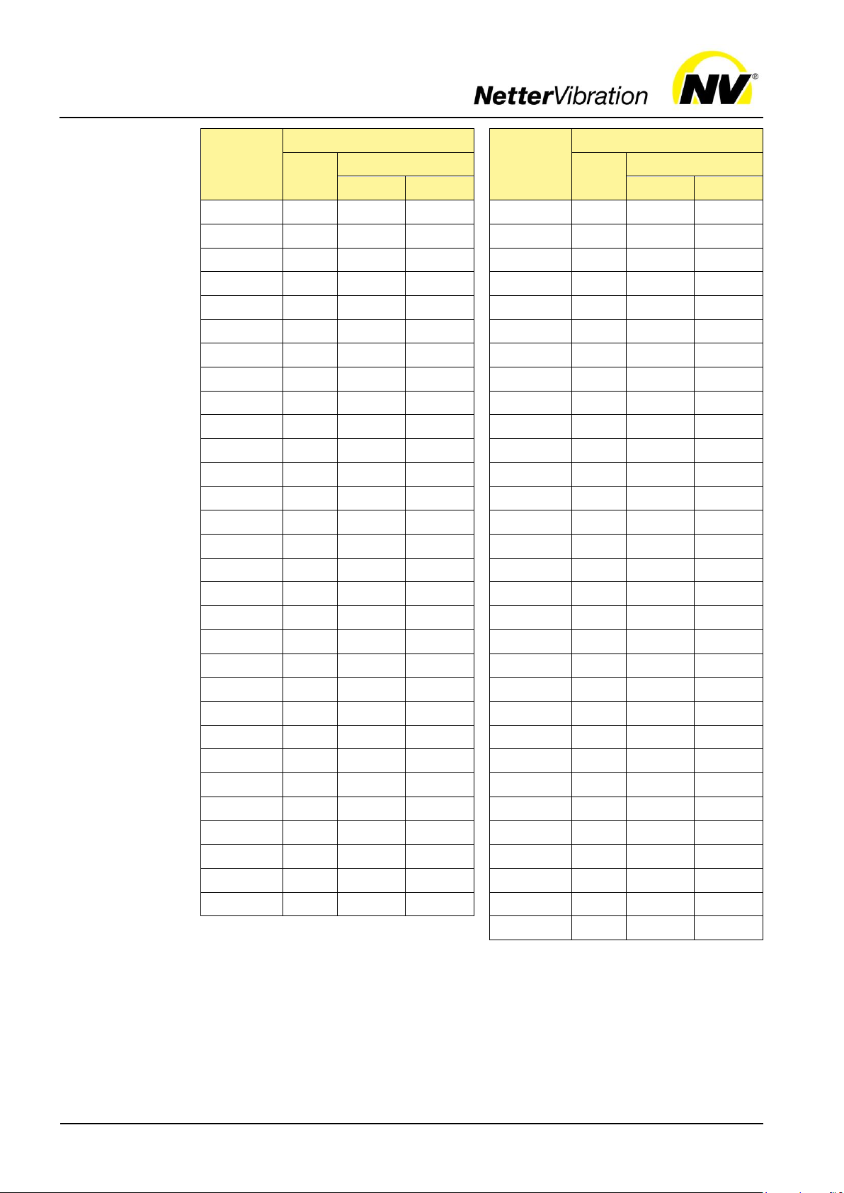
Type
M4
M5
M6
M8
M10
M12
M16
M20
M22
M24
Fastening screws and
nuts, steel
Property class 8.8*
- - 10
25
50
87
210
411
559
711
Fastening screws for XSunbalances, steel
Property class 12.9**
- - -
42
83
146
360
710
970
1225
Fastening screws and
nuts, stainless steel
8.8
21.4
44
74
183 - -
-
Terminal plate nuts, steel
1.2
2.0
3.0
6.5
13.5
- - - - -
Type
M13x1
M15x1
M20x1
M25x1.5
M30x2
M45x1.5
Locking nuts
(Pos. 21) see page 29
30
50
100
170
340
500
Type plate for
housing sizes
50 and 60
Type plate
from housing
size 100
Tightening
torques
The values can be found on the type plate. The type plate is located on the housing. For detailed technical data please refer to the brochure of the NEA/NEG.
Deviating customer-specific type plates (special designs) are possible.
Netter
Screws as supplied, without additional lubrication.
* coefficient of sliding friction 0.14 ** coefficient of sliding friction 0.15
Always use a torque wrench and tighten the screws crosswise.
Vibration recommends the following tightening torques [Nm]:

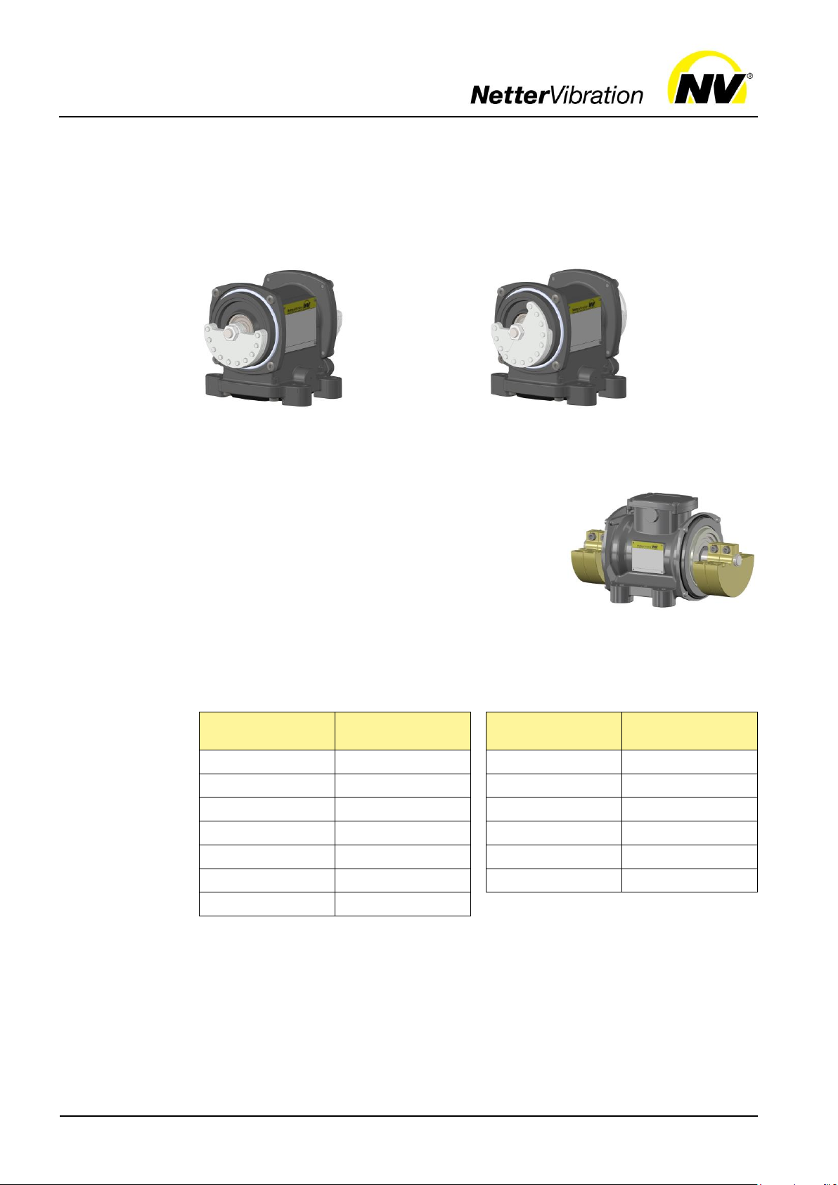
Design and function
13
Example: NEG 501140
Example: NEG 50120
Nr.
Element
Function
1
Housing
Contains and protects the components of the
NEA/NEG.
2
Unbalance covers
Protect against grabbing into the unbalances.
3
Housing foot
Attach the NEA/NEG to the mounting surface.
4
Type plate
Shows model specific information and data.
5
Terminal box
Housing sizes 101 to 120:
terminal box integrated in housing
foot.
Contains the electrical connections.
6
Cable gland
(depending on type).
Connect the NEA/NEG.
Design
Function
4 Design and function
The Electric External Vibrators of the series NEA, NEG, NEG S and NES
are asynchronous motors with adjustable weights (unbalances) mounted
on their shaft ends.
The NEA/NEG generate circular vibrations, that means the vibrations act
in all directions of a plane.
The frequency can be controlled continuously with the help of frequency
converters.
The centrifugal force can be changed by adjustment of the unbalances.

Transport and storage
14
Observe the safety instructions in Ch. Safety, from page 6 on.
Please refer to the brochure for weights and dimensions.
Transportconditions
Packaging
Storage
5 Transport and storage
When transporting the NEA/NEG, ensure that the NEA/NEG is not subjected to strong impacts or vibrations that could damage the bearings.
Please observe the following notes:
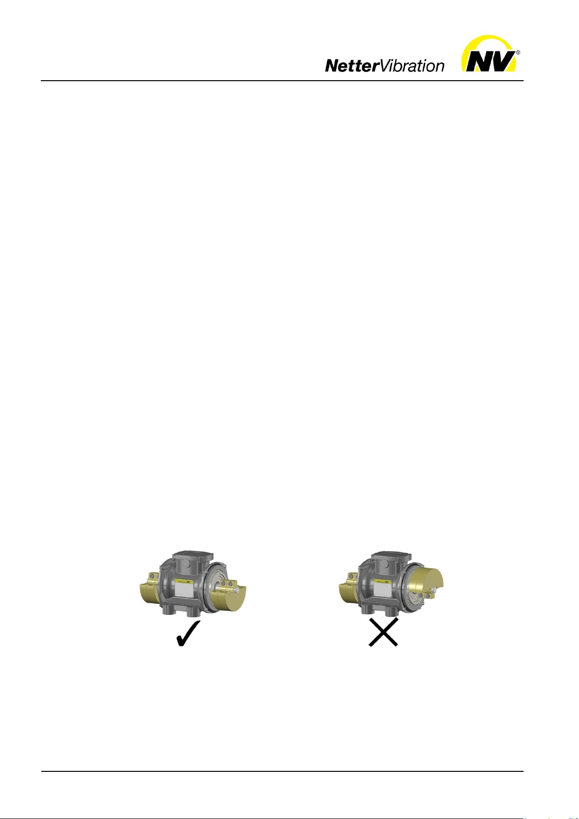
Use only the transport eyelet/eyelets (1) for lifting the NEA/NEG. If the
vibrator is fitted with two transport eyes, both must be used for lifting.
The pulling direction must not exceed 45°.
Lifting tools are of the usual kind such as a pulley or a crane. When
moving loads, use suitable steel cables or hoisting slings which are sufficiently dimensioned for these weights.
Handle the NEA/NEG very carefully during transport.
The NEA/NEG are packed ready for installation.
The packaging protects the NEA/NEG from transport damage. The packaging material has been selected from an environmentally safe and technically disposable point of view and is therefore recyclable.
The return of packaging to the material cycle conserves raw materials and
reduces the amount of waste.
Store the NEA/NEG in a dry and clean environment.
The permissible storage temperature is between -15 °C and +60 °C.
The permissible relative humidity is max. 60 %.
The storage time is max. 2 years.
If the vibrator is operated in areas with potentially explosive dust
(zone 21 or 22) a revision at
Netter
age time of more than one year.
Do not store the NEA/NEG outdoors. The electrical components are
not protected against corrosion.
Vibration is mandatory after a stor-

Installation
15
6 Installation
Observe the safety instructions in Ch. Safety, from page 6 on.
Please refer to the brochure for weights and dimensions.
3. Use an additional safety device for critical
installation situations, e.g. steel cable NSE.
Use the wire cable clamps to set the safety
cable to the shortest possible cable length.
The safety cable must always be tensioned.
Fastening
the NEA/NEG
Important: For NEA/NEG with housing size 101 to 120 the terminal box is
integrated in the housing foot. These vibrators must be electrically connected before fastening.
The NEA/NEG can be operated in any position.
1. Notice: The feet of the NEA/NEG must lie completely on the surface
so that there is no tension in the housing when tightening the fastening screw/screws, which could cause mechanical damage. The
mounting surface has to be flat (±0.1 mm flatness) and clean with no
paint residues or burn-ins.
2. The vibrators can be fastened with fastening screws of quality 8.8
(DIN 931 or 933). These must be secured with appropriate locking devices and checked and retightened at regular intervals (usually monthly). For safe fastening
Netter
Vibration recommends the use of
Netter
NBS fastening kits consisting of a screw, a special lock washer and, if
applicable, a nut.
Fasten the NEA/NEG with the fastening screws on the mounting surface. Use a torque wrench and tighten the screws crosswise. Observe
the recommended values for screw sizes and tightening torques, see
chap. Technical data, from page 11. Higher tightening torques may
cause fracture of screws or tearing of threads.
Warning: Unsuitable screw connections may cause loosening of the
NEA/NEG by vibration. This can cause damage to persons and material.

Installation
16
A suitable overload protection (1) must be
pre-connected to each vibrator. The motor
protection switches must be interlocked with
each other in pairs, so that in the event of a
motor failure, the power supply from both
motors is interrupted at the same time in order not to cause uncontrolled vibrations
which can damage the system.
In zone 21/22 the motor protection
switches must be approved for applications
in potentially explosive areas.
In areas with potentially explosive
dust (zone 21/22), an external
grounding must also be made via the
earth connection on the housing foot.
Electrical
connection
The following requirements and conditions must be met to connect the
NEA/NEG electrically:
The permissible operating conditions must be met. Please refer to
chap. Technical data, page 11 for operating conditions.
If the vibrator is operated in areas with potentially explosive dust
(zone 21/22), it is compulsory to connect the PTC-thermistor. This regulation does not apply for NEA/NEG without a PTC-thermistor.
Only suitable, flexible supply cables must be used for connecting the
NEA/NEG. The conductors in the supply cable for the connection of the
NEA/NEG to the mains must be temperature-resistant and have a sufficiently large cross-section, which is adapted to the cable length used.
The temperature resistance of the cables depends on the maximum
surface temperature (temperature class T) stated on the type plate.
When selecting the connection cables, consider that the cables are
mechanically stressed by vibration. Recommended cable types for
mains operation at 400 V, in potentially non-explosive atmosphere:
rubber hose line H07 RN-F or oil flex cable 110 CY.
For other voltages or other ambient conditions, the cables must be
adapted to the respective conditions and designed accordingly.
All electrical cables must be carefully laid and must be protected from
high temperatures, lubricants and sharp edges. Care must be taken to
ensure that the cables are not chafed through by vibrating parts. The
correct condition of the electrical cables with their plugs must be
checked at regular intervals (usually every six months). Detected errors are to be eliminated immediately.
The cable fastening must be provided in close vicinity of the cable
entrance.

Installation
17
Tighten terminal plate nuts with pre-
scribed torque, see chap. Technical data, from page 11. Remember to put the
safety washer between the ring and the
nut and the vibration-damping insert
back.
The wire ends must be fitted with suita-
ble insulated cable lugs, in order to prevent the strands from splaying.
1
Earthing terminal for protective
conductor
(green-yellow)
2
PTC-Thermistor connection
(depending on the NEG-type)
Connection
examples NEG
The electrical parameters U, I, P on the type plate must be ob-
served.
For operating the NEA/NEG in areas with potentially explosive dust
(zone 21/22) the mechanical protection of the housing must be guaranteed (degree of protection IP66, housing size 50 and 60: IP65). After
having disassembled the terminal box cover or weight covers, the condition and correct positioning of the seals has to be checked.
Open the terminal box to connect the NEG according to the type plate as
follows:
Connect the NEG according to the type plate and the following circuit diagrams.
The green-yellow protective conductor must only be connected to the
earthing terminal.

Installation
18
Series NEG / 3-phase current
Smaller voltage
Higher voltage
1: Earthing terminal for protective conductor
2: PTC-Thermistor connection (depending
on the type)
1: Earthing terminal for protective conductor
2: PTC-Thermistor connection (depending
on the type)
1
capacitor box
L1
outer conductor (brown)
N
neutral conductor (blue)
PE
protective conductor
(green-yellow)
Cable with capacitor box
Capacitor in cable
Connection
examples NEA
Connection diagram
Connect the NEA according to the type plate:
Start-up and operation
19
Observe the safety instructions in Ch. Safety, from page 6 on.
Permissible
operating
conditions
Regulations
Measures
7 Start-up and operation
Please refer to Ch. Technical data, page 11 for permissible operating conditions.
When commissioning the NEA/NEG, the rules and regulations of the
local associations for electrical engineering (e.g. VDE) and the valid
accident prevention regulations must be observed.
The NEA/NEG must always be switched on and off at the main switch.
When operating the NEA/NEG with a frequency converter, compliance
with the EMC directive must be ensured.
If the speed is controlled with a frequency converter, the maximum
centrifugal force (according to the type plate) must not be exceeded.
NEA/NEG must be adapted to your application by adjusting the unbalances. You can directly influence the vibration amplitude, centrifugal
force and current consumption.
The NEA/NEG must not be operated without the covers for the unbal-
ances. The rotating unbalances cause a risk of injury.
On initial start-up, the current consumption must be measured individ-
ually in all three phases and must correspond to the specifications on
the type plate.
The terminal box cover must never be opened in the presence of volt-
age.
Special regulations for operation in an potentially explosive at-
mosphere:
In ATEX-zones 21 and 22, the frequency converter may control the
frequency between 20 Hz and 50 Hz or 20 Hz and 60 Hz at constant
torque (linear Volt-Hertz curve). Observe maximum frequency on the
type plate.
For operation with frequency converter in ATEX-zones the PTC ther-
mistor must be connected.
The terminal box cover must never be opened in a potentially explosive
atmosphere.
NEA/NEG may only be operated in atmospheres that do not damage
the material of the vibrators.
Carry out the following measures before start-up:
1. Check that the NEA/NEG have been mounted correctly and are in perfect condition.
2. Check that the NEA/NEG have been properly connected and earthed.
Start-up and operation
20
Power supply
Supply line
connection
Adjustment of
unbalances
3. Check that the cables are undamaged and laid according to the
known regulations and standards.
4. Check that all permissible operating conditions have been observed.
5. Check that all protective measures on the system have been observed.
6. Eliminate possible errors before start-up.
7. Screw connections must be checked and, if necessary, retightened
after 1 h operating time (after initial start-up) and thereafter regularly
(generally monthly). Observe the recommended values for screw sizes and tightening torques, see chap. Technical data, from page 11
Standard network forms are TN and TT networks with an earthed star
point, as in Germany.
For overseas countries, also for countries within the EU, the mains voltage, the network configuration and the directives applicable there must
also be observed. In the case of deviations, the country, the standards, the
environmental conditions, as well as possible special features in the order,
must be agreed on in writing. If the NEA/NEG are operated and/or powered by another network configuration unknown to us, the guarantee expires completely and immediately.
The supply line must be protected according to the cross-section and the
nominal power of the NEA/NEG. The short circuit strength of this fuse
should be 25 kA.
Netter
Vibration recommends a three-phase tripping (e. g. Schneider Elec-
tric GV2 L, Tesys Model U oder Compact NS).
For all NEA/NEG there is the possibility of unbalance adjustment to direct-
ly influence vibration amplitude, centrifugal force and current consumption.
Unless otherwise specified by you, the NEA/NEG were delivered with the
standard setting (100 %). If specifications have been made by the customer, there are stickers with the current setting on the unbalance covers.
Notice: The unbalances may only be set mirror-symmetrically!

Start-up and operation
21
Type:
NEA
Unbalance
Type
Quantity
50 Hz
60 Hz
504
XL 8 8
5020
XL 8 8
5050
XL
18
18
5060
XLs 4 4
50120
XLs 6 6
50200
XLs
10
8
50300
XLs 8 6
50550
XLs
10
6
50770
XLs 8 6
2530
XLs 6 6
2570
XLs
16
10
25210
XS 4 4
25420
XS 4 4
25540
XS 4 4
25700
XS 4 4
Type:
NEG
Unbalance
Type
Quantity
50 Hz
60 Hz
5020
XL 8 8
5050
XL
18
18
5060
XLs 4 4
50120
XLs 6 6
50200
XLs
10
8
50300
XLs 8 6
50550
XLs
10
6
50770
XLs 8 6
501140
XLs
12
8
501540
XLs
12
8
501800
XLs
14
10
502020
XLs
16
10
502270
XLs
18
12
503400
XLs
12
8
503820
XLs
14
10
506220
XS 4 4
508830
XS 4 4
Number of
unbalances
Procedure:
1. Switch off the NEA/NEG at the main switch, secure against unintentional starting and ensure that there is no voltage.
2. Loosen both unbalance covers.
3. Loosen the locking nuts or locking screws.
4. Bring the unbalances to the desired setting according to the following
descriptions for the various unbalance discs. Note the mirrorsymmetrical setting.
5. Retighten the locking nuts or locking screws. Observe the recommended tightening torques, see chap. Technical data, from page 11
6. Fasten both covers for the unbalances.
The tables below show the type of unbalance and the number of unbalances per vibrator at the default setting of 100%:
Start-up and operation
22
Type:
NEG
Unbalance
Type
Quantity
50 Hz
60 Hz
2530
XLs 6 6
2570
XLs
16
10
25210
XS 4 4
25420
XS 4 4
25540
XS 4 4
25700
XS 4 4
25930
XS 4 4
251410
XS 4 4
251800
XS 4 4
252060
XS 4 4
252370
XS 4 4
253050
XS 4 4
253720
XS 4 4
254310
XS 4 4
254900
XS 4 4
256460
XS 4 4
258040
XS 4 4
258260
XS 4 4
2511210
XS 4 4
2513850
XS 4 4
1630
XLs 8 8
1690
XS 4 4
16190
XS 4 4
16310
XS 4 4
16410
XS 4 4
16500
XS 4 4
16810
XS 4 4
161130
XS 4 4
161420
XS 4 4
161610
XS 4 4
Type:
NEG
Unbalances
Type
Quantity
50 Hz
60 Hz
162110
XS 4 4
162550
XS 4 4
163030
XS 4 4
163820
XS 4 4
164700
XS 4 4
165190
XS 4 4
166270
XS 4 4
166670
XS 4 4
167890
XS 4 4
168500
XS 4 4
169510
XS 4 4
1612060
XS 4 4
1613890
XS 4 4
1617000
XS 4 4
12100
XS 4 4
12180
XS 4 4
12230
XS 4 4
12460
XS 4 4
12640
XS 4 4
12900
XS 4 4
121430
XS 4 4
122150
XS 4 4
122640
XS 4 4
122920
XS 4 4
123530
XS 4 4
124440
XS 4 4
127640
XS 4 4
128520
XS 4 4
1211070
XS 4 4
1213160
XS 4 4
1217670
XS 4 4
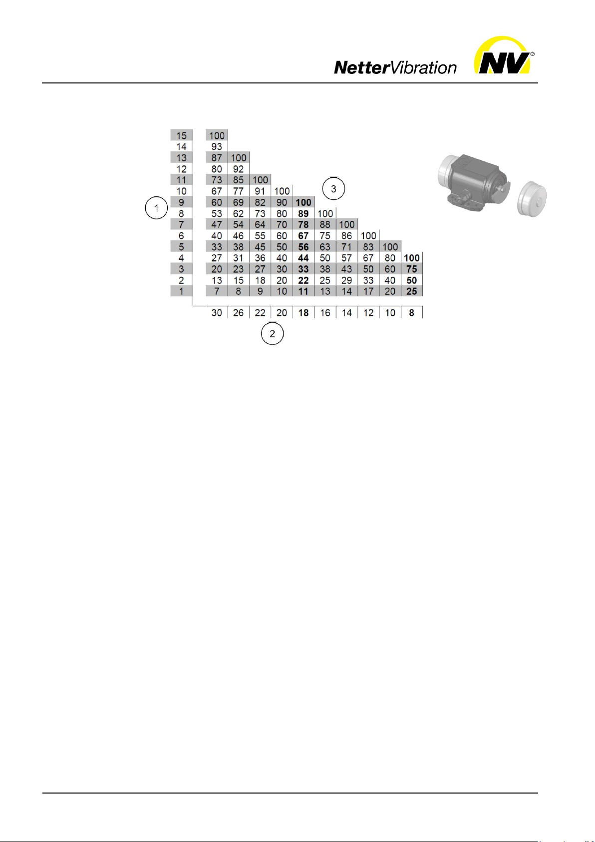
Start-up and operation
23
1: Number of unbalance discs per side
2: Default number of unbalance discs per vibrator
3: Centrifugal force in %
Unbalance
discs
type XL
The centrifugal force is adjustable with the unbalance discs (lamella) of
type XL in the following steps:
There are 2 possibilities to adjust the unbalances:
1. The unbalance adjustment (fine adjustment) is carried out by removing one unbalance disc on each side. All centrifugal values in % can
be adjusted as specified in the table.
The removed unbalance discs must be replaced by compensation
washers of identical thickness and identical inner diameter. These are
available from
Netter
Vibration.
2. The unbalance adjustment (coarse adjustment) is performed by turning one unbalance disc on each side by 180° on the shaft.
Twice the number of unbalance discs turned by 180° becomes ineffective.
Start-up and operation
24
Settings
Unbalance
per side
Type
50
Hz
60
Hz
fixed
adjust-
able
1
1
1
NEG/NEA 5060
X X
2
2
NEG/NEA 50200
NEG 501140
NEG 501540
NEG 503400
X NEG 1630
X X
NEG/NEA 50300
NEG/NEA 50770
X
3
3
NEG 501140
NEG 501540
NEG 503400
X
NEG 502270
X
4
4
NEG/NEA 2570
NEG 502020
X
2 2
1
NEG/NEA 50120
NEG/NEA 2530
X
X 2 2
1
NEG/NEA 50300
NEG/NEA 50770
X 2 2
1
NEG/NEA 50550
X
3
3
2
NEG/NEA 50200
NEG/NEA 50550
X
3
3
2
NEG/NEA 2570
NEG 501800
NEG 502020
NEG 503820
X
4
4
3
NEG 501800
NEG 503820
X
5 5
4
NEG 502270
X
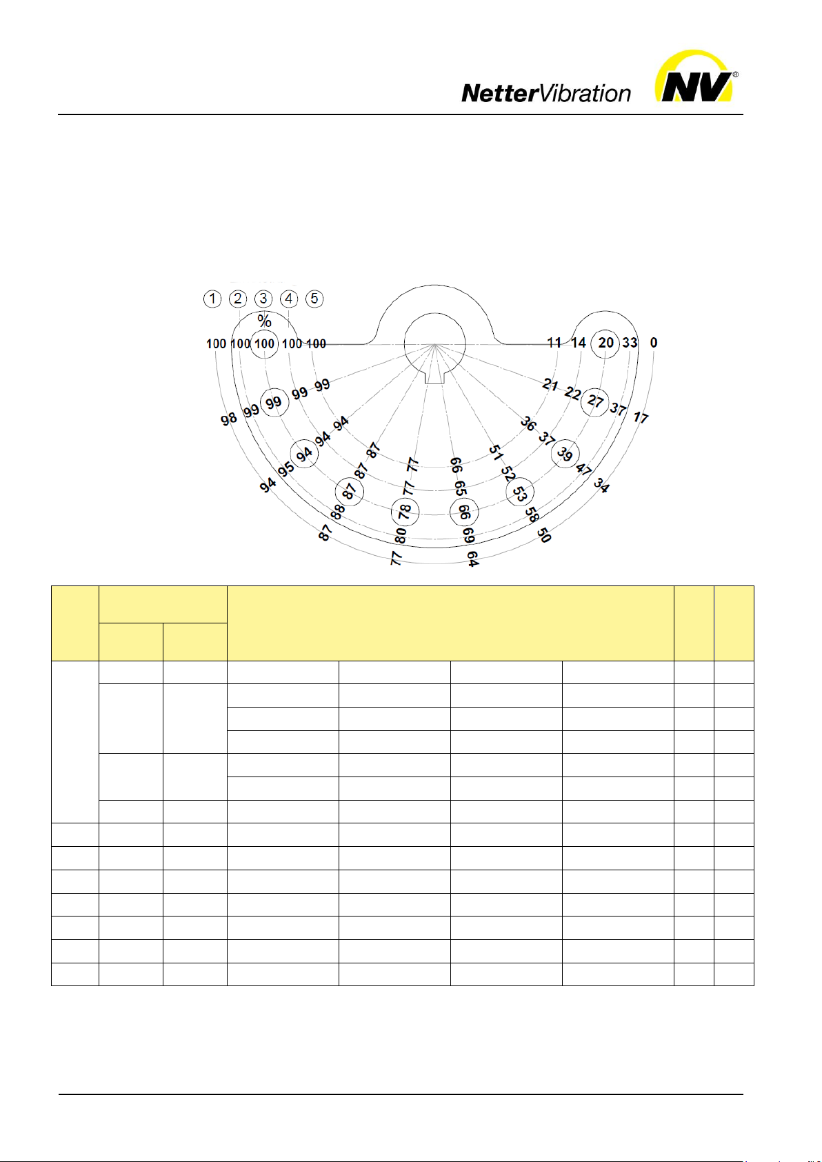
Unbalances
type XLs
The centrifugal force is adjustable with the unbalance discs (lamella) type
XLs. Adjustment of the unbalances is carried out according to a scale disc
or the supplementary sheet in the terminal box of the NEA/NEG.
By rotating the outer, adjustable unbalance disc(s) to another position, the
percentage of the centrifugal force changes as shown in the illustration
below. The grid position is defined by position pins.
Settings:
Start-up and operation
25
centrifugal force 100 %
centrifugal force 88 %
The unbalance setting of the unbalance discs
of the type XS is carried out on the scale on
the fixed unbalance.
The centrifugal force can be steplessly adjusted by turning the outer unbalance discs and
adjusting them at the partial strokes. After adjusting the unbalances, the nuts and screws
must be tightened with the specified torque.
Observe the recommended values for screw
sizes and tightening torques in chap. Technical
data, from page 11.
Adjustment
Centrifugal force in
%
0°
100
15°
98.5
30°
97
45°
92
60°
87
75°
78.5
90°
70
Adjustment
Centrifugal force in
%
105°
60
120°
50
135°
37.5
150°
25
165°
12.5
180°
0
Unbalances
type XS
Example:
NEG 50120 / 50 Hz has a total of 6 unbalance discs (3 discs per side: 2
fixed, 1 adjustable).
If a centrifugal force of 88% is desired, the adjustable unbalance discs are
rotated anticlockwise on both sides into the fourth grid position.
The centrifugal force can be adjusted according to the following table:

Maintenance and servicing
26
Observe the safety instructions in Ch. Safety, from page 6 on.
Interval
Action
If required (depending on operating
conditions)
Clean the NEA/NEG regularly with a wet cloth to remove dust
deposits.
After one hour operation after initial
start-up
Check screw connections and retighten if necessary.
Every 1000 operating hours
NEA/NEG from housing size 130 up, with speeds > 3000 rpm:
lubricate bearing with grease of the type KLUEBER
Isoflex NBU 15.
Every 5000 operating hours
NEA/NEG from housing size 130 up, with speeds < 3000 rpm:
replace the grease of the roller bearings completely, with grease
of the type KLUEBER Staburags NBU 8.
Technical data
Expertise and
regulations
Maintenance
plan
8 Maintenance and servicing
Information regarding tightening torques for screws and nuts can be found
in Ch. Technical data, page 11.
Maintenance and servicing of the vibrators may only be performed by regularly trained, authorised and qualified personnel. Work on the electrical
system may only be carried out by a qualified electrician.
The qualified personnel has to work exclusively with tools suitable for the
application.
In the case of unauthorised intervention in the NEA/NEG there is no longer
any warranty claim.
Before all maintenance and servicing work the NEA/NEG must be safely
disconnected from the electrical mains. The procedure is as follows:
1. Switch off NEA/NEG.
2. Secure against unintentional switching on.
3. Determine that NEA/NEG are voltage free.
4. Earth and short-circuit.
5. Cover and fence off neighbouring live parts.
Interventions in the NEA/NEG, such as lubricating/changing of bearings or opening the terminal box, must not be performed in potentially explosive atmospheres.
When operating in a potentially explosive dust atmosphere, the operator must regularly check the condition of the bearings and the duration of
operation of the vibrators. Damaged bearings or bearings whose service
life has been reached, must be replaced immediately. Alternatively, the
vibrators can also be sent to
Netter
Vibration for replacement of the bear-
ings.
Maintenance of the NEA/NEG must be carried out as follows:

Maintenance and servicing
27
Interval
Action
Monthly
Check screw connections and retighten if necessary.
Check ball or roller bearings and relubricate if necessary, see
section "lubrication".
Damaged bearings or bearings whose service life has been
reached, must be replaced immediately.
Check cable supply line.
Every 6 month
Check proper condition of connecting cables and plugs.
Every 2 years
Replace O-rings and plastic seals .
At least every 4
years
Check proper condition of electrical systems and stationary electrical equipment.
Type
NEA
Lubrication
Bearing
life [h]
50 Hz
Bearing
life [h]
60 Hz
504
PL*
> 100,000
> 100,000
5020
PL*
92,118
22,745
5050
PL*
8,087
2,236
5060
PL*
> 100,000
5,044
50120
PL*
18,075
18,075
50200
PL*
3,363
2,572
50300
PL*
4,003
3,588
50550
PL*
4,148
4,219
Type NEA
Lubrication
Bearing
life [h]
50 Hz
Bearing
life [h]
60 Hz
50770
PL*
7,509
6,257
2530
PL*
> 100,000
> 100,000
2570
PL*
> 100,000
> 100,000
25210
PL*
23,406
19,200
25420
PL*
15,135
12,635
25540
PL*
6,266
4,224
25700
PL*
19,477
16,231
Notes on
lubrication
Lubrication /
bearing life
NEA
Other maintenance and repair work are to be carried out exclusively by
Netter
Vibration.
NEA/NEG up to the housing size 130 have ball bearings. These are lubricated for their service life (permanent lubrication).
NEA/NEG from the housing size 130 up have roller bearings. These are
lubricated with the grease of the type KLUEBER Staburags NBU 8 EP. At
speeds up to 3000 rpm the bearings are lubricated for a period of at least
5000 operating hours. After this time the grease of the bearings has to be
replaced completely.
The lubrication intervals must be considerably shortened under more difficult operating conditions.
The housing sizes can be found in the brochure of the NEA/NEG.
Type of lubrication of the bearings and bearing life of the NEA:
*PL = permanent lubrication

Maintenance and servicing
28
Type
NEG
Lubrication/
grease
quantity [g]
Bearing
life [h]
50 Hz
Bearing
life [h]
60 Hz
5020
PL*
92,118
22,745
5050
PL*
8,087
2,236
5060
PL*
> 100,000
5,044
50120
PL*
18,075
18,075
50200
PL*
3,363
2,572
50300
PL*
4,003
3,588
50550
PL*
4,148
4,219
50770
PL*
7,509
50980 9 5,062
4,833
501140 9 3,029
4,219
501540
16
4,038
4,219
501800
16
2,416
1,833
502020
30
7,070
8,372
502270
30
4,775
4,558
503400
40
8,672
10,267
503820
40
5,856
5,591
506220
120
5,743
4,636
508830
150
9,029
2,790
2530
PL*
> 100,000
> 100,000
2570
PL*
> 100,000
> 100,000
25210
PL*
23,406
19,200
25420
PL*
15,135
12,635
25540
PL*
6,266
4,224
25700
PL*
19,477
16,231
25930 9 12,103
10,190
251410
16
10,870
8,330
251800
30
22,231
20,009
252060
30
14,300
12,300
252370
35
16,159
13,032
253050
35
7,100
5,900
253720
40
12,228
11,086
Type
NEG
Lubrication/
grease
quantity [g]
Bearing
life [h]
50 Hz
Bearing
life [h]
60 Hz
254310
40
8,200
7,300
254900
80
9,930
8,648
256460
120
10,478
8,451
258040
150
9,029
7,575
258260
180
11,460
7,881
2511210
260
10,576
8,718
2513850
300
9,000
6,200
1630
PL*
> 100,000
> 100,000
1690
PL*
> 100,000
> 100,000
16190
PL*
> 100,000
72,171
16310
PL*
> 100,000
> 100,000
16410
9
> 100,000
> 100,000
16500
9
> 100,000
39,516
16810
PL*
> 100,000
60,144
161130
PL*
54,020
42,632
161420
PL*
25,100
20,000
161610
30
29,165
29,270
162110
30
11,800
10,400
162550
32
17,701
12,292
163030
32
41,500
30,500
163820
60
13,073
10,842
164700
80
18,364
15,425
165190
100
19,206
15,157
166270
120
15,786
13,144
166670
120
13,767
14,000
167890
150
14,431
12,276
168500
150
11,266
9,379
169510
180
10,728
10,972
1612060
260
11,000
11,800
1613890
300
13,327
11,510
1617000
360
11,273
10,404
Lubrication /
bearing life
NEG
Type of lubrication or grease quantity of the bearings and bearing life of
the NEG:
*PL = permanent lubrication

Maintenance and servicing
29
Type
NEG
Lubrication/
grease
quantity [g]
Bearing
life [h]
50 Hz
Bearing
life [h]
60 Hz
12100
PL*
> 100,000
> 100,000
12180
PL*
> 100,000
> 100,000
12230
9
> 100,000
> 100,000
12460
PL*
> 100,000
> 100,000
12640
PL*
> 100,000
> 100,000
12900
30
> 100,000
65,414
121430
32
> 100,000
39,702
122150
60
> 100,000
29,320
122640
80
> 100,000
41,200
Type
NEG
Lubrication/
grease
quantity [g]
Bearing
life [h]
50 Hz
Bearing
life [h]
60 Hz
122920
100
> 100,000
43,076
123530
120
> 100,000
35,405
124440
150
> 100,000
32,368
127640
180
29,652
10,982
128520
260
52,762
18,667
1211070
300
37,822
15,233
1213160
360
35,257
12,684
1217670
400
22,520
9,347
Lubrication
or replacement of
bearings
*PL = permanent lubrication
The item numbers refer to the spare parts list.

Maintenance and servicing
30
3. Disassemble unbalances type XS:
After removing the circlip (20) and loosening the clamping screws (16), the unbalances can be removed.
Disassemble unbalances type XL and
type XLs:
Screw a long screw with the same thread
into a tapped hole for the fastening screws
(24) of the unbalance cover. Put a lever between the unbalance discs and this long
screw. After loosening the locking nut (21),
the unbalances can be removed from the
shaft.
1. Switch off NEA/NEG, secure against switching on again and ensure
that it is volt-free.
2. Loosen screw (24) and remove unbalance covers (23).
4. Remove bearing (10):
up to housing size 120: Remove circlip (40).
Starting from housing size 130: loosen screws (4) and remove
flange (3). Remove circlip (40) from flange (3).
5. Replace both bearings (10) or remove old grease (e. g. with benzine)
and smear the specified amount (see table) of new grease (according
to the maintenance plan) evenly.
6. Assembly is carried out in the reverse order.
7. Tighten locking nuts (21) and screws (4, 16) to the specified tightening
torque.

Troubleshooting
31
Observe the safety instructions in Ch. Safety, from page 6 on.
Fault
Possible cause
Troubleshooting
Action
Vibrator does not start or
runs at too low speed
Phase interruption
Check fuse and connection
cable
Replace fuse and/or connection cable
Mains voltage too low
Check mains voltage and
cable cross-section
Correct mains voltage, replace cable
Vibrator speed drops under
load
Wiring wrong
Check circuit diagram
Inadequate contact of a
connection point
Check connections in the
terminal box
Tighten terminal plate nuts
Phase interruption
Check fuse and connection
cable
Replace fuse or connection
cable
Incorrectly dimensioned
connection cable
Check cable cross section
Replace cable
Overload
Check setting of unbalance
Reduce unbalances
Mains voltage too low
Check mains voltage and
cable cross-section
Correct mains voltage, replace cable
Expertise and
regulations
Troubleshooting
9 Troubleshooting
Troubleshooting of the vibrators may only be performed by regularly
trained, authorised and qualified personnel. Work on the electrical system
may only be carried out by a qualified electrician.
The qualified personnel has to work exclusively with tools suitable for the
application.
In the case of unauthorised intervention in the NEA/NEG there is no longer
any warranty claim.
Before any troubleshooting the NEA/NEG must be safely disconnected
from the electrical mains. The procedure is as follows:
1. Switch off NEA/NEG.
2. Secure against unintentional switching on.
3. Determine that NEA/NEG are voltage free.
4. Earth and short-circuit.
5. Cover and fence off neighbouring live parts.
Interventions in the NEA/NEG must not be performed in potentially ex-
plosive atmospheres.

Troubleshooting
32
Fault
Possible cause
Troubleshooting
Action
Excessive heating
of the vibrator
Wiring wrong / overload
Check circuit diagram
Mains voltage too low
Check mains voltage and
cable cross-section
Correct mains voltage, replace cable
Too much grease in bearings
Fill in correct ammount of grease
No grease or not enough
grease in bearings
Fill in correct ammount of grease
Foreign body in bearings
Clean bearings, replace if necessary
Vibrator hums
Phase interruption
Check fuse, mains voltage
and connection cable
Correct mains voltage, replace fuse or cable
Short-circuit between turns in
the stator winding
Replace vibrator
Circuit braker fails when
switched on
Phase interruption
Check fuse and connection
cable
Replace fuse or connection
cable
Overload
Check unbalance settings
Reduce unbalance
Short circuit in winding
Replace vibrator
High current consumption
Natural resonance range of
vibration system
Measure current consumption
Stiffen device
Bounce impacts
Measure current consump-
tion
Reduce power of vibrator
Loose fastening
Tighten screws

Spare parts and accessories
33
Ordering of
spare parts
10 Spare parts and accessories
Please provide the following details when ordering spare parts:
type designation according to the type plate
serial number according to the type plate
description and position number of spare part
required amount
Example NEG 50300
Example NEG 501140
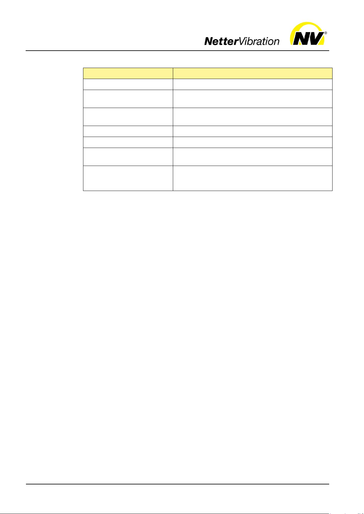
Spare parts and accessories
34
Component
Description
Shim washers
Compensation for removed unbalance discs.
CC-unbalances
Depending on the direction of rotation, two different
unbalances can be achieved.
Fastening kit NBS
Recommended for secure and permanent fastening of
the NEA/NEG.
Frequency converters
For frequency-controlled operation.
Brake accessories
Enable rapid deceleration of vibrators.
PTC thermistor
PTC 120°C thermistor for safe operation of the vibrators.
Special versions
NEA/NEG are also available in special versions, e.g. for
special voltages or the use in potentially explosive atmospheres. Information on request.
Accessories
The following accessories are available for NEA/NEG:
Further electrotechnical accessories on request.

Disposal
35
11 Disposal
All parts of the NEA/NEG must be properly disposed of according to the material specifications. The valid disposal prices of
the NEA/NEG are available on request.
Material
Part
Stainless steel
Unbalance covers
Steel
Rotor, unbalances, flange, bearings, screws, washers, nuts
Aluminium
Housing, type plate
Plastic
Seals, terminal box block
Copper with resin
Winding
Material
Part
NEG housing types
I, II and III
NEG housing type
IV
NES and NEG S
Stainless steel
Unbalance covers
Housing, unbalance
covers, terminal box
block and cover
Steel
Housing size 140
and 160, rotor, unbalances, flange,
bearings, screws,
washers, nuts
Housing, rotor, unbalances, flange,
bearings, screws,
washers, nuts
Rotor, unbalances,
flange, bearings,
screws, washers,
nuts
Aluminium
Housing, type plate,
terminal box cover
Housing size 150
and 170 up to 210,
unbalance covers,
type plate, terminal
box cover
Type plate
Plastic
Seals, terminal box
block
Seals, terminal box
block
Seals
Copper with resin
Winding
Winding
Winding
Prices
Materialspecifications
All parts of the NEA/NEG can be recycled.
Type: NEA
Type: NEG and stainless steel versions NES and NEG S
 Loading...