

Montage- und Kurzbetriebsanleitung für
Druckluftvibratoren der Serien NCB, NCR und NCT
S i c h e r h e i t
Stellen Sie sicher, daß während der
Montage oder bei sonstigen Arbeiten
am Vibrator und an den Zuleitungen,
die Druckluft abgestellt ist. Vor Inbetriebnahme müssen Schlauchleitun-
gen fest verbunden sein.
Ein unter
Schlauch, kann Verletzungen verursachen.
Beachten Sie die beiliegenden Zeichnungen.
Druck
stehender,
sich
lösender
A l l g e m e i n e H i n w e i s e
Die Vibratoren der Serien NCB, NCR und
NCT entsprechen der EG-Maschinenrichtlinie
2006/42/EG. Insbesondere sind die Normen
DIN EN ISO 12100 Teil 1 und 2 beachtet.
Diese Vibratoren erzeugen ungerichtete
Schwingungen.
Sie werden zur Bunkerentleerung, als Antriebe
für Rutschen, Siebe und Vibrationstische eingesetzt. Allgemein zum Lösen, Fördern, Verdichten und Trennen von Schüttgütern und zur
Minderung von Reibung.
Bei Beachtung der Betriebsvorschriften des
Betreibers können sie für die Herstellung von
Lebensmitteln, sowie in Naßbereichen eingesetzt werden.
Die Vibratoren können im Freien eingesetzt werden.
Änderungen am Gerät können die
Eigenschaften des Vibrators verändern bzw. das Gerät zerstören und
führen zum Erlöschen aller Ansprüche.
Überprüfen Sie nach 1 h und danach regelmäßig
(i.d.R. monatlich) die Befestigungsschrauben.
Vibrationen können ein Lösen der Schraubverbindungen und Geräte verursachen. Schäden
an Personen und Material können die Folge sein.
Die Frequenz und die davon abhängige Zentrifugalkraft werden durch den Betriebsdruck bestimmt.
Antriebsmittel: Saubere, gefilterte (Filter < 5µm)
Druckluft oder Stickstoff, von 2 bis 6 bar.
Nicht gefilterte Luft führt zum Ausfall der
Vibratoren.
Alle Vibratoren können ölfrei betrieben
werden, ein Nebelöler verlängert die
Lebensdauer von NCB und NCR.
Maximaler Betriebsdruck: 6 bar.
Lärmpegel: Je nach Typ (mit Schalldämpfer)
und 6 bar Luftdruck bei 75 bis 85 dB(A), bei niedrigerem Luftdruck darunter. Der Betrieb ohne
Schalldämpfer ist zu vermeiden, um die Umgebung nicht mit hohen Lärmwerten zu belasten.
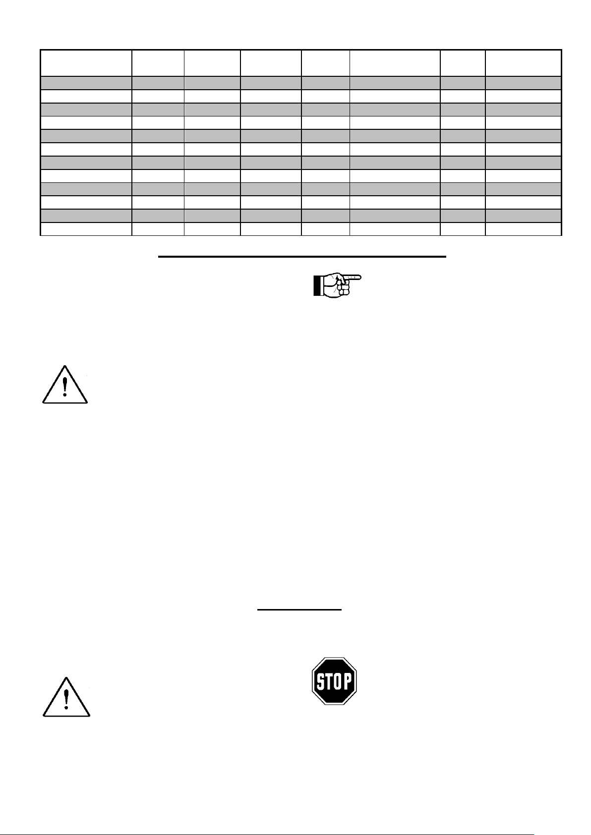
Die Montage erfolgt mit zwei Befesti-
gungsschrauben auf einer sauberen
und planen Oberfläche (Schrauben-
größe und Anzugsmomente siehe
Tabelle).
Montieren Sie selbsthemmende Schraubensi-
cherungsscheiben (keine Federringe).
Verwenden Sie gegen Lösen selbstsichernde
Muttern oder z.B. Loctite 270.
Besonders empfohlen wird ein Versteifungsprofil (U-Stahl) als Unterbau zu verwenden.
Dieses Versteifungsprofil ist an das Objekt
anzuschweißen. Damit kann die Vibrationsenergie optimal übertragen werden.
Der Lufteingang hat eine kleinere
Öffnung als der Luftausgang.
Beide sind frontseitig durch Pfeile
gekennzeichnet.
M o n t a g e
Zuleitung: Der Luftwiderstand nimmt mit der
Schlauchlänge zu. Die in der Tabelle angegebenen Nennweiten gelten für Schlauchlängen
bis 3 m. Längere Zuleitungen benötigen größere Querschnitte.
Ableitung: Wird die austretende Luft abgeführt
und soll der Vibrator die volle Leistung erzielen,
muß der Abgangsschlauch eine größere
Nennweite haben als der Zuleitungsschlauch.
Im Freien darf kein Regenwasser oder eine andere Flüssigkeit in das Gehäuse laufen. Besteht
die Gefahr, daß z.B. Regenwasser durch den
Luftausgang in das Gehäuse läuft, ist die Abluft
durch einen nach unten gebogenen Schlauch
abzuführen.
Die Druckluftzuführung ist sicher zu befestigen.
Die Verwechslung von Luftein- und Luftausgang bedeutet Leistungsverlust.
Typ
Gewinde
Anzugs-
moment
Anschluß-
gewinde
Zulei-
tung
Einsatz im bzw.
unter Wasser
Nebelöl
Temperatur-
bereich
NCB 1, 2
M 6
10 Nm
G 1/8
NW 6
nein
empfohlen
-20°C - 200°C
NCB 3, 5, 10, 20
M 8
25 Nm
G 1/4
NW 9
nein
empfohlen
-20°C - 200°C
NCB 50, 70
M 10
50 Nm
G 3/8
NW 12
nein
empfohlen
-20°C - 200°C
NCR 3
M 6
10 Nm
G 1/8
NW 6
nein
empfohlen
-20°C - 200°C
NCR 10, 22
M 8
25 Nm
G 1/4
NW 9
nein
empfohlen
-20°C - 200°C
NCR 57
M 12
87 Nm
G 3/8
NW 12
nein
empfohlen
-20°C - 200°C
NCR 120
M 16
210 Nm
G 3/8
NW 12
nein
empfohlen
-20°C - 200°C
NCT 1, 2, 3, 4
M 6
10 Nm
G 1/8
NW 6
ja
nein
-20°C - 120°C
NCT 5, 10
M 8
25 Nm
G 1/4
NW 9
ja
nein
-20°C - 120°C
NCT 15,29
M 8
25 Nm
G 1/4
NW 9
ja
nein
-20°C - 120°C
NCT 55, 108
M 10
50 Nm
G 3/8
NW 12
ja
nein
-20°C - 120°C
NCT 126, 250
M 16
210 Nm
G 3/8
NW 12
ja
nein
-20°C - 120°C
I n b e t r i e b n a h m e u n d B e t r i e b
Die Inbetriebnahme der Vibratoren kann nach
fachgerechter Montage sofort erfolgen.
Stellen Sie sicher, daß der in der Betriebsanleitung angegebene Luftverbrauchswert vom
Druckluft-System auch geliefert werden kann.
Sonst wird der Vibrator die technischen Daten
nicht erreichen.
Zulässige Betriebsbedingungen:
Umgebungstemperaturen
NCB / NCR -20°C bis 200°C
NCT -20°C bis 120°C.
NCB- und NCR-Vibratoren: Betriebstempera-
turen über 120°C erfordern den Einsatz von
Anschlußtüllen und Schalldämpfern in temperaturbeständiger Ausführung. Sofern vorhanden
Nebelöler einstellen (2 bis 5 Tropfen/h).
Checkliste für Montage und Inbetriebnahme:
1. Geräte sorgfältig montieren.
2. Befestigungsschrauben sichern.
3. Wartungseinheit (Filter, Regler), Ventil, Zu-
leitung montieren.
NCT-Vibratoren: Der Betrieb in
Flüssigkeiten setzt die Abführung der
Druckluft an die Atmosphäre voraus.
Hinweis NCT 1 und NCT 2:
Wegen des hohen Wirkungsgrades erreichen
diese beiden Geräte sehr hohe Drehzahlen.
Die hohen Drehzahlen setzen die Lagerstandzeit herab und erhöhen den Lärmpegel. Deshalb empfehlen wir, die NCT 1 und NCT 2 nur
mit 2 bis 3 bar (max. 15.000 Umdrehungen) zu betreiben oder nur im Intervallbetrieb einzusetzen.
4. Falls erforderlich, Nebelöler einstellen (2 bis
5 Tropfen/h) und Abluft ableiten.
5. Prüfen: Befestigungsschrauben gesichert?
6. Prüfen: Angaben über Schlauchlänge und
Nennweite beachtet?
NCB-, NCR- und NCT-Vibratoren sind wartungsfrei. Sie können äußerlich mit Druckwasser gereinigt werden. Danach die Vibratoren
kurz betätigen.
Entsorgung: Alle Geräte können je nach
Material fachgerecht über den Hersteller entsorgt werden.
W a r t u n g
Filter bei Bedarf entleeren, Filtereinsatz und
Schalldämpfer reinigen (auswaschen).
Schraubverbindungen sind nach
Unsaubere Druckluft führt zur Verschmutzung von Filter und Schalldämpfer.
Wartungsanleitung und Störungsbeseitigung siehe Betriebsanleitung.
Die gültigen Entsorgungspreise erhalten Sie
auf Anfrage.
1 h Betriebszeit und danach regelmäßig (i.d.R. monatlich) zu
überprüfen und gegebenenfalls
nachzuziehen.
Concise installation and operating instructions for
pneumatic vibrators series NCB, NCR and NCT
S a f e t y
Make sure that the compressed air is
shut off during installation or during
other work on the vibrator and on the
supply lines. Before starting operation
all hoses must be tightly connected.
A hose coming loose under pressure may
cause injury.
Observe the enclosed drawings.
G e n e r a l N o t e s
The vibrators comply with the EC machine
regulation 2006/42/EC.
The standards DIN EN ISO 12100 part 1 and
part 2 particularly have been observed.
The vibrators produce non-directed vibrations.
They are used for emptying bunkers, to drive
chutes, screens and vibrating tables. Generally
for loosening, conveying and separating of bulk
materials and for the reduction of friction.
When observing the operating instructions of
the customer they may also be used in food
processing or wet environments.
The vibrators may be used outdoors.
The frequency and the dependent centrifugal
force are determined by the operating pressure.
Alterations to the unit may change
the characteristics of the vibrator or
even damage the unit and will cause
the rejection of any warranty claims.
Screw connections must be checked after 1 hour
and then controlled at regular intervals (normally
each month).
Vibrations can cause loosening of bolted connections and equipment. This may cause damage to
persons and material.
Drive medium: Clean, filtered (filter < 5µm),
compressed air or nitrogen of 2 to 6 bar (30 to
90 PSI) is required.
Non-filtered air will damage the vibrators.
The vibrators are designed for
lubrication-free operation. The life
time of NCB and NCR will be
extended with lubrication
Maximum operating pressure: 6 bar (90 PSI).
Noise level: Depending on the type of vibrator
and air pressure the noise level is 75 to 85
dB(A) (with silencer). If the air pressure is
lower, the noise level is also lower. In order to
avoid unnecessary noise, the vibrators should
not be operated without a silencer.
I n s t a l l a t i o n
The unit must be fastened to a
clean and level surface with two
fastening screws (for screw size
and tightening torque see table).
Use self-locking washers (no spring washers).
Use self-locking nuts or e.g. Loctite 270 against
loosening.
It is strongly recommended to use a stiffening
(U-profile) for the substructure. This stiffening
section should be welded to the object. This
allows optimal transfer of the vibration energy.
The air inlet port is smaller than the
outlet port. Both are marked by
arrows on the front.
Supply line: The air resistance increases with
the hose length. The nominal widths in the table
apply for hose lengths of up to 3 m. Longer
supply lines need bigger cross-sections.
Air discharge: If the out flowing air is
discharged and the vibrator should work with
full power, the discharge hose must have a
bigger nominal width than the supply hose.
Rainwater or other fluids must not enter the
housing when using outside. In case of raining
the exhaust air should be discharged downwards.
The compressed air supply line must be fastened securely.
Swapping the air inlet and outlet ports will
cause loss in power.

Type
Thread
Tighte-
ning
torque
Supply line
thread
Supply
line
diameter
For use in
or under
water
Lubricator
Temperature
range*
NCB 1, 2
M 6
10 Nm
G 1/8
DN 6
no
recommended
-20°C to 200°C
NCB 3, 5, 10, 20
M 8
25 Nm
G 1/4
DN 9
no
recommended
-20°C to 200°C
NCB 50, 70
M 10
50 Nm
G 3/8
DN 12
no
recommended
-20°C to 200°C
NCR 3
M 6
10 Nm
G 1/8
DN 6
no
recommended
-20°C to 200°C
NCR 10, 22
M 8
25 Nm
G 1/4
DN 9
no
recommended
-20°C to 200°C
NCR 57
M 12
87 Nm
G 3/8
DN 12
no
recommended
-20°C to 200°C
NCR 120
M 16
210 Nm
G 3/8
DN 12
no
recommended
-20°C to 200°C
NCT 1, 2, 3, 4
M 6
10 Nm
G 1/8
DN 6
yes
no
-20°C to 120°C
NCT 5, 10
M 8
25 Nm
G 1/4
DN 9
yes
no
-20°C to 120°C
NCT 15,29
M 8
25 Nm
G 1/4
DN 9
yes
no
-20°C to 120°C
NCT 55, 108
M 10
50 Nm
G 3/8
DN 12
yes
no
-20°C to 120°C
NCT 126, 250
M 16
210 Nm
G 3/8
DN 12
yes
no
*) -20°C to 200°C corresponds to -4°F to 392°F. -20°C to 120°C corresponds to -4°F to 248°F
S t a r t - u p a n d O p e r a t i o n
The start-up of the vibrator is possible immediately after the correct installation.
Make sure that the pneumatic system is able to
supply the air quantity specified in the operating
instructions. Otherwise the vibrator will not be
able to reach the technical specifications.
Permissible operating conditions:
Ambient temperature range*
NCB/NCR -20°C to 200°C
NCT -20°C to 120°C
NCB and NCR vibrators require heat resistant
hose nipples and silencers for temperatures
above 120°C (248°F). If necessary install lubricator and adjust oil flow (2 to 5 drops/h).
Checklist for Assembly and start-up:
1. Install the unit carefully.
2. Secure the fastening screws.
3. Install maintenance unit (filter, regulator),
valve and supply line.
NCT Vibrators may be operated
inside liquids if the exhaust air is
piped off to the atmosphere.
Note NCT 1 and NCT 2:
Due to the high efficiency these units reach
very high rotary speeds.
These high speeds reduce the lifetime of the
bearings and increase the noise level. We
therefore recommend to operate NCT 1 and
NCT 2 only with 2 to 3 bar (max. 15.000 rpm) or
to use them for interval operation.
4. If necessary install lubricator and adjust oil
flow (2 to 5 drops/h), drain off exhaust air.
5. Check: Are fastening screws secured?
6. Have notes on hose length and nominal
width been observed?
NCB, NCR and NCT vibrators are maintenance-free. They can be cleaned with a water
jet from outside. Then operate the vibrator for a
short while after.
For maintenance instructions and trouble shooting refer to the operating instructions.
Waste disposal: The parts must be disposed
off according to valid regulations, depending on
the material.
M a i n t e n a n c e
Dirty compressed air causes clogging of filter and silencer.
If necessary empty the filter, clean filter element
and silencer (wash out).
Screw connections must be checked
and retightened after 1 hour of
operation and then at regular
intervals (normally every month).
All units can be disposed of through your
supplier. The valid waste disposal prices are
available on request.

Résumé des instructions d’installation et de service
pour vibrateurs pneumatiques NCB, NCR et NCT
S é c u r i t é
Assurez-vous, lors du montage ou
de tous autres travaux effectués
sur le vibrateur ou les conduites
d’amenée, que l’alimentation en air
comprimé est débranché. Avant la
mise en service, il est nécessaire que les conduites flexibles soient solidement fixées.
Un flexible sous pression qui se détache peut
provoquer des blessures.
Tenez compte des croquis ci-joints.
R e m a r q u e s g é n é r a l e s
Les vibrateurs NCB, NCR et NCT correspondent à la directive Machines 2006/42/CE.
Il a été tenu compte des normes DIN EN ISO
12100 1
Ces vibrateurs génèrent des vibrations
multidirectionnelles.
Ils sont utilisés pour le vidage de silos,
l’entraînement de goulottes, de tamis et de
tables vibrantes et, en général, pour décolmater,
transporter, compacter et séparer les matières
en vrac et réduire les frictions.
Si les prescriptions d’emploi élaborées par
l’utilisateur sont respectées, ils peuvent être mis
en œuvre pour la fabrication de denrées alimentaires ainsi qu’en milieu humide.
Les vibrateurs peuvent aussi fonctionner à
l’extérieur.
La fréquence et la force centrifuge sont déterminées par la pression de service.
re
et 2e parties.
Toute modification du vibrateur est
susceptible d’en altérer les propriétés ou de le détruire et entraîne
l’extinction des droits de garantie.
Les raccords vissés et les appareils peuvent se
desserrer sous l’effet des vibrations, ce qui
risque de provoquer des dommages corporels
et matériels.
Les vissages devront être vérifiés au bout d’une
heure de service, puis régulièrement (en général
chaque mois).
Fluide d’entraînement:
d’entraînement est l’air comprimé exempt
d’impuretés et filtré (filtre < 5 µm), ou l’azote,
sous une pression de 2 à 6 bars (30 à 90 PSI).
L’utilisation
défaillance des vibrateurs.
Pression maximale de service : 6 bars (90 PSI).
Niveau de bruit : En fonction du type de
vibrateur (avec silencieux) et pour une pression
de 6 bars, (90 PSI) le niveau de bruit est
compris entre 75 et 85 dB(A). Il est plus faible
quand la pression est moindre. Ne pas faire
fonctionner le vibrateur sans silencieux pour ne
pas provoquer des nuisances sonores inutiles.
d’air
Les vibrateurs sont conçus pour
fonctionner sans huile, un graisseur
prolongera la durée de vie des NCB
et NCR.
non
filtré
Le
entraîne la
fluide
M o n t a g e
Le montage est réalisé par deux
vis de fixation sur une surface
propre et plane (taille des vis et
couples de serrage, voir tableau) et avec des
rondelles d’arrêt autobloquantes (pas de
rondelles-ressorts). Contre le desserrage,
utilisez des écrous indesserrables ou un agent
liquide anti-desserrage, par ex. Loctite 270.
Nous recommandons de prévoir comme
support un profilé de raidissement (fer U)
soudé sur l’objet à vibrer, ce qui permet une
transmission optimale de l’énergie de vibration.
L'entrée d'air a une ouverture plus
petite que l'air de sortie. L’entrée
d’air et la sortie d’air sont identifiées
par des flèches sur le vibrateur.
Conduite d’amenée : La résistance de l’air
augmente avec la longueur des flexibles. Avec
des flexibles d’une longueur maximum de 3 m,
nous recommandons les sections figurant dans
le tableau. Pour les conduites d’amenée plus
longues, nous recommandons des sections
plus importantes.
Conduite d’évacuation : Si l’air sortant est
évacué, il est nécessaire que le flexible
d’évacuation présente un diamètre supérieur à
celui de la conduite d’amenée d’air.
En plein air, l'eau de pluie ou tout autre liquide
ne doit pas couler dans le corps. Si il y a danger que, par exemple, de l'eau de pluie pénètre par la sortie d'air alors l'air doit être évacué à l'aide d'un tuyau courbé vers le bas.
L'arrivée d'air comprimée doit être fixée en tout
sécurité.
La méprise entre l'entrée et la sortie d'air
entraine une perte de puissance.

Type
Filetage
Couple de
serrage
Filetage
Conduite
d’amenée
Utilisation
dans ou
sous l’eau
plage de
température
NCB 1, 2
M 6
10 Nm
G 1/8
DN 6
non
recommandé
-20 à 200°C
NCB 3,5,10,20
M 8
25 Nm
G 1/4
DN 9
non
recommandé
-20 à 200°C
NCB 50, 70
M 10
50 Nm
G 3/8
DN 12
non
recommandé
-20 à 200°C
NCR 3
M 6
10 Nm
G 1/8
DN 6
non
recommandé
-20 à 200°C
NCR 10, 22
M 8
25 Nm
G 1/4
DN 9
non
recommandé
-20 à 200°C
NCR 57
M 12
87 Nm
G 3/8
DN 12
non
recommandé
-20 à 200°C
NCR 120
M 16
210 Nm
G 3/8
DN 12
non
recommandé
-20 à 200°C
NCT 1, 2, 3 , 4
M 6
10 Nm
G 1/8
DN 6
oui
non
-20 à 120°C
NCT 5, 10
M 8
25 Nm
G 1/4
DN 9
oui
non
-20 à 120°C
NCT 15, 29
M 8
25 Nm
G 1/4
DN 9
oui
non
-20 à 120°C
NCT 55, 108
M 10
50 Nm
G 3/8
DN 12
oui
non
-20 à 120°C
NCT 126, 250
M 16
210 Nm
G 3/8
DN 12
oui
non
-20 à 120°C
M i s e e n s e r v i c e e t u t i l i s a t i o n
À l’issue d’un montage approprié, la mise en
service du vibrateur peut intervenir immédiatement. Assurez-vous que la consommation d’air
indiquée dans les instructions de service peut
être effectivement fournie par votre système
d’alimentation en air comprimé. Sinon, le vibrateur ne pourra atteindre les caractéristiques
techniques prévues.
Conditions de service admissibles :
températures ambiante
NCB / NCR -20°C à 200°C
NCT -20°C à 120°C.
Les vibrateurs NCB et NCR : Des températures d’utilisation entre 120°C et 200°C nécessitent des raccords et des silencieux appropriés.
Régler le graisseur éventuel (2 à 5 gouttes/h).
Check-list de montage et de mise en service :
1. Monter soigneusement l’appareil
2. Serrer et bloquer les vis de fixation.
3. Monter l’unité de conditionnement (filtre,
régulateur), la vanne et la conduite d’amenée.
Pour l’utilisation des NCT sous
l’eau l’échappement doit se faire a
l’air libre.
Remarque concernant le NCT 1 et le NCT 2 :
En raison de leur degré d’efficience élevé, ces
appareils atteignent des vitesses de rotation
très élevées. Les vitesses élevées restreignent
la longévité des paliers et accroissent le niveau
de bruit. C’est pourquoi nous vous recommandons de ne faire fonctionner les NCT 1 et
NCT 2 qu’avec une pression maximale de 2 à 3
bars (15 000 tours maximum) ou de ne les
utiliser que par intervalles.
4. En cas de nécessité, régler le graisseur (2 à
5 gouttes/h) et évacuer l'air sortant.
5. Vérification : Les vis de fixation sontelles freinées?
6. La longueur des flexibles et leur diamètre
nominal ont-elles été respectées?
Les NCB, NCR et NCT ne réclament pas
d’entretien. Ils peuvent être nettoyés extérieurement à l’eau sous pression. Après le nettoyage,
faire brièvement fonctionner le vibrateur.
Instructions d’entretien et élimination des défaillances: voir les instructions de service.
Élimination: Les éléments devront être éliminés
de manière appropriée en fonction du matériau
dont ils sont composés.
E n t r e t i e n
En cas de nécessité, purger le filtre, nettoyer la
garniture du filtre et le silencieux (en les lavant).
Les visses devront être vérifiés
âpres la première heure de ser-
L’air chargé d’impuretés provoque
l’encrassement du filtre et du
silencieux.
Tous les appareils peuvent être éliminés par
l’intermédiaire de votre fournisseur. Sur demande, nous vous communiquerons les prix
d’élimination en vigueur.
vice, puis régulièrement (tous les
mois). Le cas échéant, les vis seront
resserrées.

Betriebsdruck
Pressure
Pression
NCB / NCR
5µm
Filter erforderlich
NCB / NCR
-20°C - 200°C
-4°F - 392°F
NCT
Öl / Oil / Huile
NCT
6 bar / 90 PSI max.
-20°C - 120°C
-4°F - 248°F
Filter required
Filtre nécessaire
Jan. / Feb. / ...

 Loading...