

Page 1
Operating instructions for
Netter pneumatic impactors
of the series PKL
These operating instructions apply to: PKL 190
PKL 450
PKL 740
Sept. 2017
No. 1468E
Page 1/26
PKL 2100
PKL 5000
PKL 10000
Page 2

2
Contents
1 General information 3
2 Safety 5
3 Technical data 7
4 Design and function 10
5 Transport and storage 11
6 Installation 12
7 Start-up and operation 21
8 Maintenance and serv ici ng 22
9 Troubleshooting 23
Scope of
delivery
Designation
Version
number
10 Spare parts and accessories 24
11 Disposal 25
12 Annex 26
Please refer to the delivery note for the scope of delivery.
Check the packaging for possible transport damage. In the event of
damage to the packaging, check the contents for completeness and
possible damage. Infor m the carr i er in the cas e of damag e.
The pneumatic impactors of the series PKL are hereafter referred to as
„PKL“.
document no. 1468E
version no. 1
date of issue Sept. 2017
Page 3

General information
3
1 General information
Use and
storage
Target group
Copyright
Limitation of
liability
Before installing the PKL read these operating instructions carefully. It is
the basis for any action when dealing with the PKL, and may be used for
training purposes. The operating instructions should be subsequently
stored at the operation site.
The target group for these operating instructions is technical staff, who
have basic knowledge in pneumatics and mechanics.
Therefore, only staff who are trained in these fields may work on the PKL.
The PKL may only be installed, put into operation, maintained, troubleshot
and disassembled by persons authorised by the operator.
This documentation is protec t ed by copyright.
NetterVibration reserves all rights such as translations, reprinting and re-
production of the operati ng instr uc tions, as well as parts thereof.
All technical information, data and instructions for installation, operation
and maintenance in these operating instructions are based on the latest
information available at the time of printing and take our past experience
to the best of our knowledge into account.
No claims can be derived from the information, illustrations and descriptions in these operating instructions.
The manufacturer does not assume liability for damages resulting from:
• failure to observe the operating instructions,
Directives /
standards
observed
Special features of the
PKL
• improper use,
• unauthorised repairs,
• technical modifications,
• use of non-permiss ibl e spar e part s.
Translations are made to the bes t o f our know l edg e.
NetterVibration does not assume liability for translation errors, even if the
translation was made by us or on our behalf. Only the original German text
remains binding.
The pn eum atic i mpa ctors of the series PKL comply with the EC Machinery
Directive 2006/42/EC.
In particular, the standard EN ISO 12100 has been observed.
• high impact force
• low air consumption
• reduced sound level due to an elastomer impact plate
Page 4
General information
4
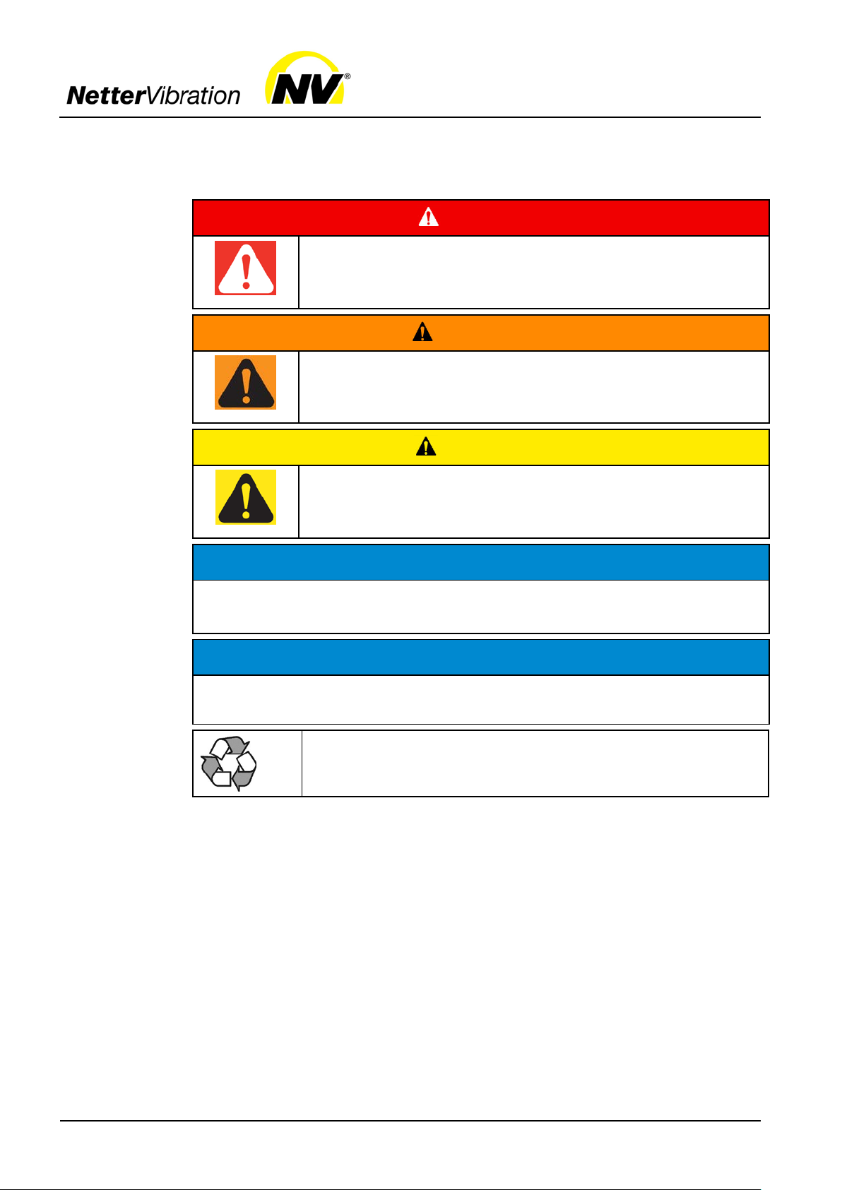
DANGER
Disregard of this notice will result in death or severe bodily
WARNING
Disregard of this notice can result in death or severe bodily
CAUTION
Disregard of this notice can result in minor or moderate
Instruction
and warning
symbols
Personal
injuries
Material
damages
Notes
The following instruction and warning symbols are used in these operating
instructions:
signifies an immediate danger.
injuries.
signifies a potential danger.
injuries.
signifies a potentially dangerous situation.
bodily injuries.
NOTICE
signifies potential material damage.
Disregard of this notice can result in material damage.
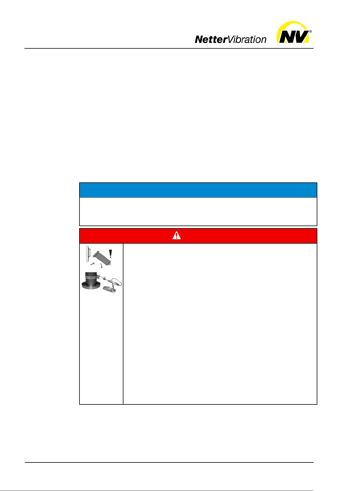
IMPORTANT
indicates actions, methods or notes that are not relative to safety, e.g. useful information and tips.
Environmentally safe disposal
indicates the obligation of environmentally safe disposal.
Page 5
Safety
5
assumes no liability for personal injuries and material
damages if technical changes to the product were made or the notices and
DANGER
, construction parts as well as fastening and locking
The PKL 190, PKL 450 and PKL 740 are open on the
tionally with an impact plate and two damper rings
(flange and impact plate) or with an EE kit and a damper
operation and thereafter at regular intervals (generally
2 Safety
Intended use
Qualification
of qualified
personnel
Liability
Falling parts
General areas of application of the PKL are for knocking off adhesive bulk
materials from container walls (e.g. silos, hoppers, filter outlets, pipelines
and reactors) and for emptying residues from weighing containers. The
PKL also prevent bridging and rat-holing, so that the material can continuously flow.
The PKL can be used outdoors and in dusty environments, however not in
water or any other liquids.
PKL may only be operated with a timed on/off sequence.
Any other use is considered improper.
Installation, commissioning, maintenance and troubleshooting of the PKL
may only be performed by authorised qualified personnel
All handling of the PKL is the responsibility of the operator.
IMPORTANT
NetterVibration
regulations in these operating instructions were not obs er v ed.
Falling parts
The PKL
screws can come loose due to vibration. Falling parts lead to
severe personal injuries.
Use only Netter fastening kits (NBS) to fasten the PKL.
side of impaction. During installation ensure that the impact piston remains in the housing .
Mount the PKL 2100, PKL 5000 and PKL 10000 addi-
ring (flange).
Check the fastening and locking screws after one hour of
monthly).
Retighten the fastening and locking screws, if necessary.
A safety device with a safety cable is mandatory for criti-
cal mounting situations.
Page 6
Safety
6
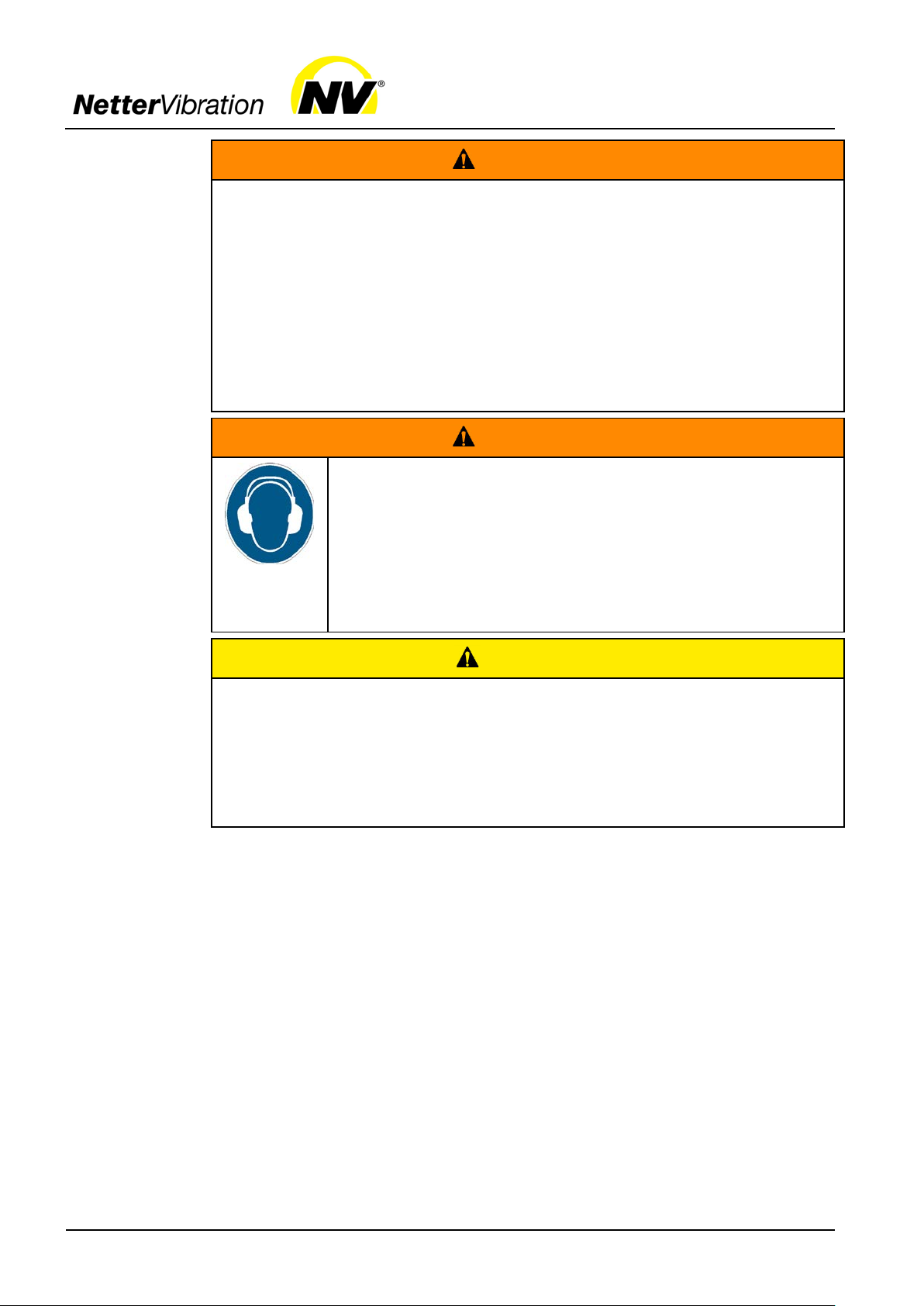
Check the hose lines and connections after one hour of operation and
Ensure that the compressed air is disconnected from the supply lines
dB(A). Human
Use hearing protection during work in a noisy area if
are not mechanically closed on the side of impact. The impact
piston and/or the impact plate are loosely mounted. Falling parts can lead
Ensure that the impact piston and/or impact plate remain in the housing
Compressed
air
Sound level
Loose parts
WARNING
Compressed air
A loosened hose which is under pressure can lead to personal injuries.
Screw the hose lines on carefully.
thereafter regularly (generally monthly).
Retighten the hose lines, if necessary.
during all work on the PKL.
Prevent the PKL from being switched back on during all work.
WARNING
Sound level
Near the PKL or near constructions connected to the PKL E
the sound pressure level may exceed 80
hearing can be permanently damaged by high noise levels.
80 dB(A) is exceeded.
Mount the PKL preferably with an EE kit.
CAUTION
Loose parts
The PKL
to personal injuries and material damage.
when mounting and disman tl ing.
Page 7
Technical data
7
≤
3 Technical data
Parameters
Type
designation
Permissible
operating
conditions
Type:
PKL...
190/4 0.19 0.43 4.0 0.20 0.8 1 - 2
190/6 0.19 0.60 6.0 0.20 0.8 1 - 2
450/4 0.44 0.56 4.0 0.40 1.6 1 - 3
450/6 0.44 0.92 6.0 0.60 1.6 1 - 3
740/3 0.74 1.30 3.0 0.50 2.6 2 - 4
740/4 0.74 1.80 4.0 0.70 2.6 2 - 4
740/5 0.74 2.10 5.0 0.80 2.6 2 - 4
740/6 0.74 2.70 6.0 1.00 2.6 2 - 4
2100/4 2.10 4.20 4.0 5.20 6.7 3 - 5
2100/5 2.10 6.20 5.0 6.50 6.9 3 - 5
5000/4 4.96 6.60 4.0 5.70 16.0 4 - 8
5000/6 4.96 10.60 6.0 8.60 16.5 6 - 12
10000/6 10.00 17.50 6.0 15.10 34.0 > 10
*) The force of impact corresponds to the impact of the given weight falling from a height of 1 m.
Weight
of piston
[kg]
Force of
impact *
[kg]
Optimum
operating
pressure
[bar]
Air consumption/impact at optimum pressure
[Nl]
Overall
weight
[kg]
Suitable
for wall
thickness
of...
[mm]
The type designation of the PKL has the suffix /3, /4, /5 or /6. The suffix is
derived from the optimum operating pressure, i.e. the PKL 740/4 achieves
the optimal effect at an operating pressure of 4 bar.
Drive
medium
NetterVibration recommends operating the PKL with clean, oiled com-
pressed air.
Filter
5 µm, quality class in accordance with ISO 8573-1
The PKL are, in principle, s uita bl e for operat io n with oi l -free compressed
air or nitrogen .
Lubrication ISO viscosity class in accordance with DIN 3448, VG 5 bis 15
Fill mist lubricator with acid- and resin-free compressed air oil.
Ambient
temperature*
Recommendation for temperatures
of up to 60 °C:
Klüber „AIRPRESS 15"
Standard: -20 °C to 60 °C HT versions: -20 °C to 160 °C de-
Recommendation for temperatures
over 60 °C with HT-versions:
Aral „Farolin U“ lubrication oil
pending on version
The permissible ambient temperatures must not fall below or exceed the
above temperatures during operation.
Operating
pressure*
Operating pressures must be between 2,0 bar and 6,0 bar.
The actual air pressure set on the regulator must not exceed the optimum
operating pressure by more than 1 bar.
Impact
frequency
The following impact sequence must not be exceeded:
Maximum 10 strokes in sequence at an impact frequency of
15 strokes/min and 180 strokes/h.
*) Higher operating pressures and temperatures are per mitted only after cons ultation with and written consent
by the application technicians of NetterVibration.
Page 8
Technical data
8
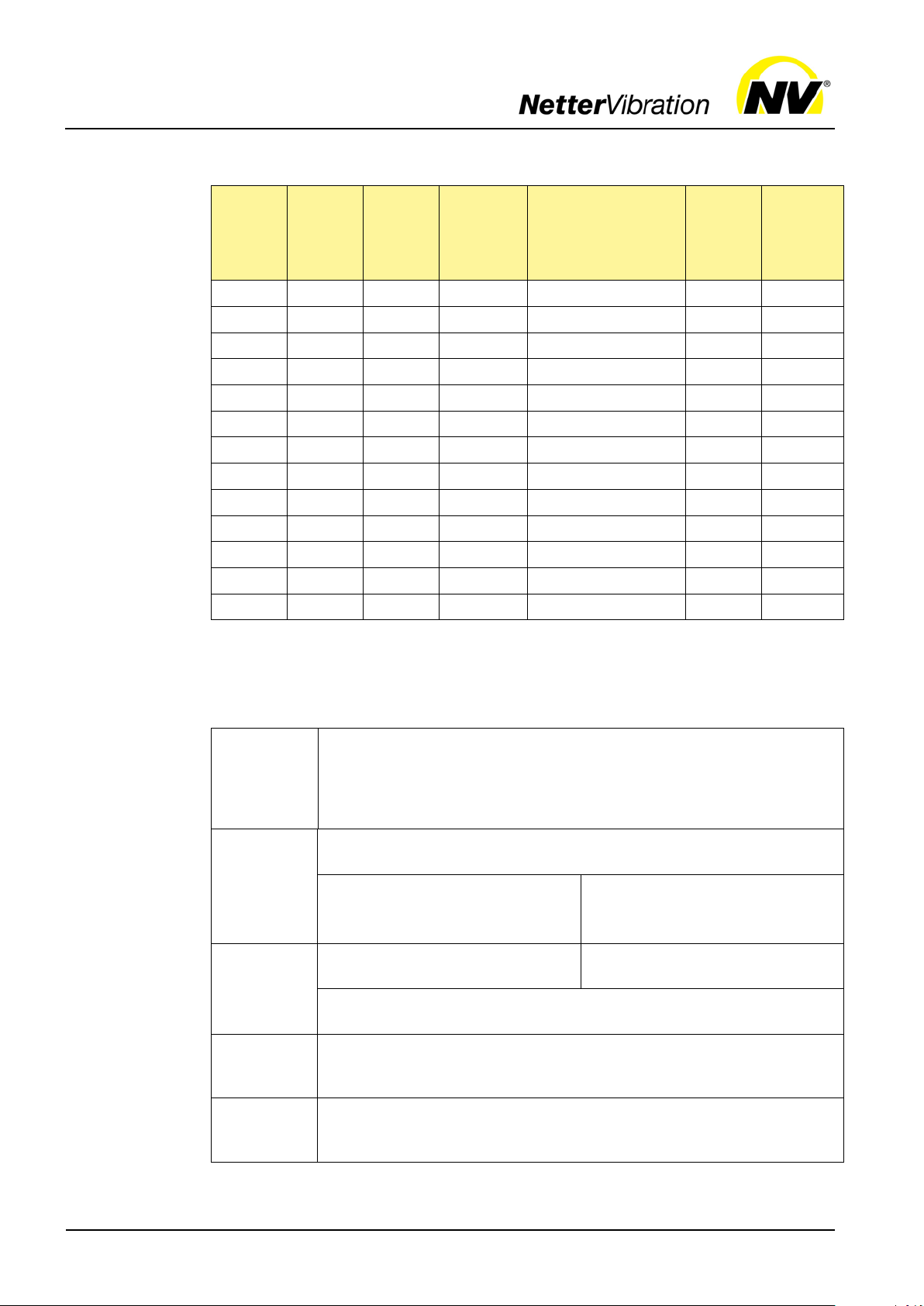
Noise level
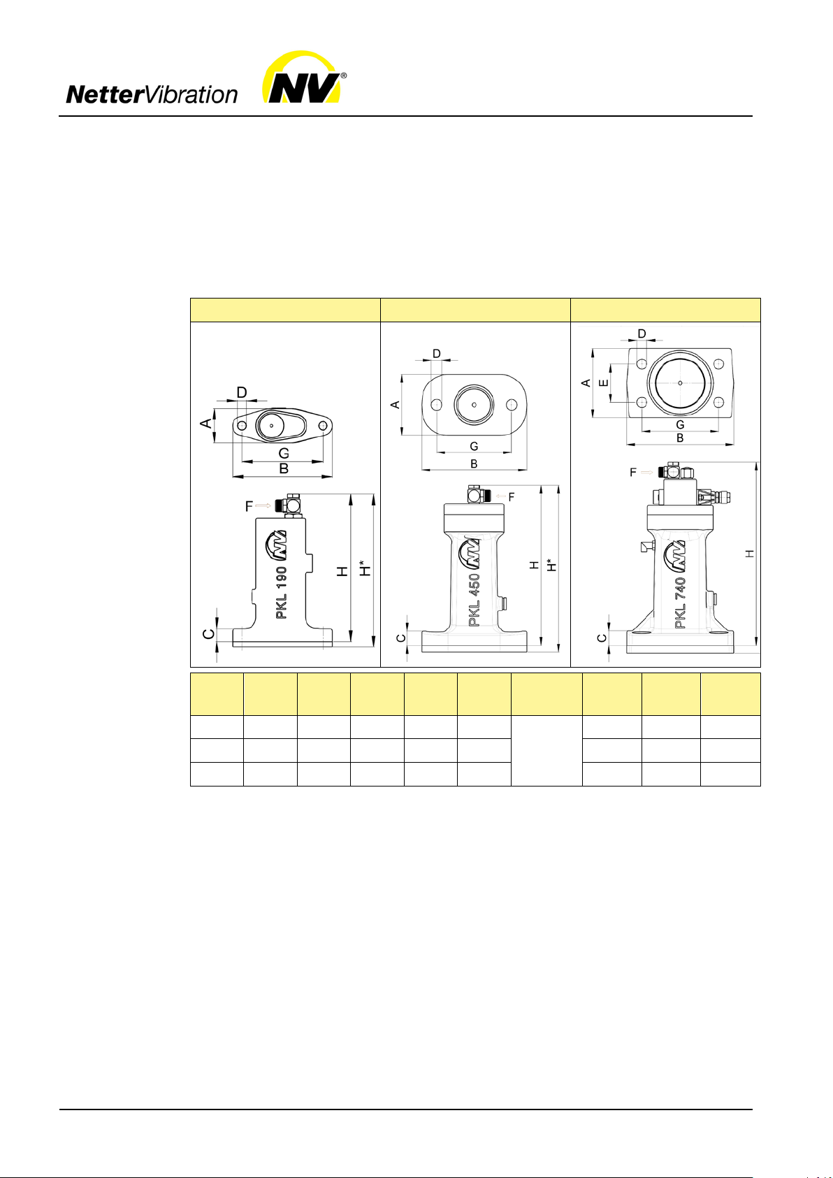
Dimensions
PKL
190 /
450 /
740
The noise level of the PKL may exceed 80 dB(A) (single noise incident).
Depending on the impact sequence the continuous noise level is below
this value.
The PKL should be preferably mounted with the EE kit. The noise reduction is about ca. 5 dB(A) (single noise incident).
The sound em itted by the PKL can be dampened by hoods (on request).
This is only worthwhile if the impacted sheet metal is also insulated (e.g.
by heat insulation material).
PKL 190 PKL 450 PKL 740
Type:
PKL... A [mm] B [mm] C [mm]
190 38.0 111 15 9.0 - G 1/8,
450 73.5 126 14 13.0 - 90.0 192.0 200.0
740 90.0 140 15 13.0 50 100.0 238.5 248.5
*) with EE kit
Ø D
[mm] E [mm] F
NW 6 × 1
G
[mm] H [mm]
90.0 163.5 169.5
H*
[mm]
Page 9

Technical data
9
Dimensions
PKL
2100 /
5000 /
10000
PKL 2100
PKL 5000
PKL 10000
Type:
PKL...
2100 Ø120.0 Ø180 17 13.0 - G 1/8,
5000 Ø114.3 Ø180 22 17.0 - Ø152 376.5
10000 Ø 145.0 Ø220 25 17.0 - Ø185 445.0
A
[mm]
B
[mm] C [mm]
Ø D
[mm] E [mm] F
G
[mm] H [mm]
Ø152 300.5
NW 6 × 1
Page 10

Design and function
10
1
Quick air-exhaust valve
2
Silencer
3
Springs
4
Piston
5
Flange
6
Impact plate
4 Design and function
Design
Function
Features of
PKL 740
ST kit
EE kit
p Compressed air
F Impact force
The PKL is a pneumatic „hammer“. Compressed air (p) goes under the
piston (4) and presses it against one or two springs (3).
When exhausting, the air chamber beneath the piston empties abruptly via
the quick air-exhaust valve (1).
The piston (4) (hammer) is struck by the spring force against an impact
plate (6), which then passes the impact force (F) on. For PKL without an
impact plate (PKL 190, PKL 450 and PKL 740), the piston strikes directly
against the fastening surface. The impact plate in the standard types (PKL
2100, PKL 5000 and PKL 10000) is always made of steel and can also be
replaced by an elastomer impact plate, if necessary.
The air escapes via the silencer (2).
The PKL only work when mounted, as the piston chamber is then sealed
by a built-in O-ring in the mounting surface.
A quick-air exhaust valve and a 3/2-way valve are integrated in the valve
head of the PKL 740. Therefore, the control valve on the customer's site
can be mounted at any distance away from the PKL 740.
The control air must be connected at the side. A silencer is mounted on
the exhaust air outlet.
The ST kit allows a continuous impact sequence with permanent compressed air supply.
The EE kit reduces the noise level and generates a rubber hammer effect.
Page 11

Transport and storage
11
1
Plastic fastening
4
Corrugated cardboard disc
2
Damper ring (for steel impact plate)
5
Damper plate (flange)
3
Impact plate
5 Transport and storage
Transport
conditions
Packaging
Transport
safety device
PKL
2100 /
5000 /
10000
Special transport conditions are not required.
When moving the PKL 10000, use the mounted transport lugs at the top of
the housing.
The PKL are packed and ready for assembly. Accessories and add-on
parts are delivered unmounted, unless otherwise agreed upon.
The packaging protects the PKL from transport damage. The packaging
material has been selected from an environmentally safe and technically
disposable point of view and is therefore recyclable.
The return of packaging to the material cycle conserves raw materials and
reduces the amount of was te.
Storage
The PKL 2100, PKL 5000 and PKL 10000 are delivered with a transport
safety device at the bottom. The transport safety device consists of 2 plastic fastenings and a corrugated cardboard disc. It prevents the impact plate
from falling out during transport and must be removed before installation.
Take care that the impact plate and damper plate retain their position on
the PKL, as they must be mounted with the PKL.
• Store the PKL in a dry and clean environment.
• The storage temperature is between -20 °C and +60 °C.
• Close all openings when re-storing.
• Preserve the PKL befor e storag e:
1. Screw or clamp the PKL on a plate. The impact plate of the PKL
2100, PKL 5000 and PKL 10000 must be inserted.
2. Apply anti-corrosion oil to the air inlet and briefly activate the PKL.
Page 12

Installation
12
6 Installation
IMPORTANT
1
Elastomer disc
2
Spacer plate
3
O-ring
The spacer plate is delivered together with
Safety
instructions
Procedure
Instructions
for EE kit
PKL
190 /
450 /
740
Observe the safety instructions in Ch. Safety, page 5.
When installing the PKL carry out the following steps in succession:
Install the EE kit on the PKL 190 / 450 / 740 between the flange of the PKL
and the mounting surface so that
• the piston of the PKL strikes the elastomer disc (1).
• the O-ring (3) is between the spacer plate (2) and the mounting sur-
face.
Example: PKL740
For detailed information, please refer to the mounting instructions for the
respective PKL type.
EE kit:
the O-ring.
Page 13

Installation
13
1. Remove the steel impact plate with the O-ring (2) and the damper ring
ring (3) in such a way that the
1
Damper ring
(impact plate)
2
Steel impact plate with O-ring
3
EE kit:
EE impact plate with O-ring
The EE impact plate is delivered
Instructions
for EE kit
PKL
2100 /
5000
Install the EE kit on the PKL 2100 / 5000 as foll ows:
(impact plate, 1).
2. Insert the EE impact plate with the Opiston of the PKL strikes against the EE impact plate (3).
Ensure that the damper ring (flange, x) is between the flange of the PKL
and the mounting surface.
x Damper ring (flange)
x Damper ring (flange)
together with the O-ring.
Example: PKL 2100
For detailed information, please refer to the EE kit mounting instructions
for PKL 2100 / 5000.
Page 14

Installation
14
1
Saddle plate
2
Weld-on plate
3
EE kit
4
NBS G (fastening set for
tapped hole)
Fastening
devices
NetterVibration delivers the appropriate fastening devices for installation
of the PKL:
weld-on consoles or weld-on plates (±0.3 mm flatness)
• Weld the consoles directly onto the c o ntai n er walls.
• Weld the plates onto previously mounted saddle plates (1.5 times the
sheet thickness of the container).
Weld-on console, plane (left) and round (right)
Fastening
kits
Weld-on plate
For safe and permanent fixation of the PKL to the device use the compulsory fastening kits.
The following versions are available for every PKL type:
Description Difference
NBS ... G (e.g. NBS 5000 G) for tapped hole
NBS ... D (e.g. NBS 740 D) for through-hole
NBS ... (e.g. NBS 190) without screws
... corresponds to the PKL type: 190 / 450 / 740 / 2100 / 5000 / 10000
Page 15

Installation
15
1
Hexagon bolt
2
NBS lock plate
3
Washer
4
Damper spring
5
Washer
(only for NBS D)
6
Tab washer with long tap
(only with NBS D)
7
Nut (only for NBS D)
The damping springs must be
Tighten the screw connections
Loosen the screw connections
ng roundings
of the lock plates towards all bolt
heads, with NBS D also towards all
For NBS D fold all long taps of the
tab washers towards the mounting
Instructions
fastening kit
Components of the fastening kit using the
example NBS D:
mounted on the flange of the PKL.
1.
evenly, until the damping springs
are completely pressed together.
2.
by one revolution.
Then fold all protrudi
nuts, as follows:
For detailed information, please refer to the respective Mounting Instructions (NBS G mounting kits or D mounting kits).
plate.
Page 16

Installation
16
Instructions
for ST kit
Components
for all
installations
Specifications
for valves and
hoses
The ST kit connects the control port to the piston chamber. The PKL
equipped with the ST kit strikes as long as there is compressed air.
• For PKL 190 / 450 proceed as follow s :
- Mount the ST screw fitting (after the NBS).
- A 3/2-way valve with air supply is necessary.
• For PKL 740 proceed as follows:
- Replace the silencer with the compressed air connection.
- Only one air supply is necessary.
• Order the PKL 2100 directly with the ST control.
• For PKL 5000 proceed as follow s:
- Mount the control valve of the ST control to the PKL.
- The control valve is connected internally to the piston chamber, the
ST control is integrated in the PKL.
For detailed information, please refer to the Assembly Instructions for the
ST kit.
For all installations, use a ball valve to shut off the main line and a maintenance unit.
The maintenance unit should comprise a filter, a regulator and a mist lubricator (see Ch. Technical data, page 7; "Drive medium").
Connect the PKL with the pneumatic hose according to the following depicted pneumatic circuit diagrams.
Define the impact sequence of the PKL with an electrical control, e.g. the
Netter Electronic Timer AP 117. Electrical or pneumatic controls are available on request.
Recommended cross-sections for control lines, control valves and main air
supply: NW 6 × 1
To connect the control valve to the PKL:
• NW 6 should be used and
• a length of 15 m should not be exceeded.
For simultaneous oper ati on o f sev er al PKL
• larger cross-sections are to be provided for the main line up to distribution to the individual PKL.
• the total length of the compressed air supplies is max. 50 m.
Page 17

Installation
17
1
Electronic Timer AP
2
Ball valve
3
Maintenance unit
4
3/2-way v alve
1
Electronic Timer AP
2
Ball valve
3
Maintenance unit
4
Actuating valve on customer's site
5
Control line
6
Main air
only PKL
way valve integrated
t at
the valve head. The control line
(5) from the actuating valve on
the customer's site (4) to the
may be very long (e.g. 50
m). The charging time of the
is several seconds for
For long air lines, set a pause
and duty time on the Electronic
least 5 seconds. If shorter lines
hese times
Standard
installation
PKL 190 /
450 /
2100 /
5000 /
10000
Example: PKL 450
Use a 3/2-way valve (4) for actuation.
By switching the valve, the piston chamber is vented and exhausted and the PKL therefore
strikes.
Mount the 3/2-way valve (4) at a
distance of max. 15 m.
Standard
installation
PKL 740
The PKL 740 is the
with a 3/2in the valve head.
By switching the valve, the piston chamber is vented and exhausted and the PKL therefore
strikes.
The main air (6) is presen
PKL
PKL
longer supply and control lines.
Timer AP (1) to a minimum of at
are used, reduce t
accordingly, e.g. to 2-3 seconds.
Page 18

llation
18
1
Electronic Timer AP
2
Ball valve
3
Maintenance unit
4
Actuating valve on customer's site
5
3/2-way air valve
The main air is always at the
way air valve (5) max. 1 m
line from the actuating valve (4)
on the customer's site to the
For longer supply and control
lines, the charging time of the
is several seconds. For
a pause and
er AP (1) to a minimum of at
least 5 seconds. If shorter lines
are used, reduce these times
1
Electronic Timer AP
2
Ball valve
3
Maintenance unit
4
Actuating valve on customer's site
5
3/2-way air valve
Operate several PKL in parallel
The connection lines from the
long, otherwise the
the PKL moves too slowly and
If required, install the actuating
valve (4) at a larger distance if
way air valves (5)
Installation
with long
supply line
PKL
190 /
450 /
2100 /
5000
Example: PKL 450
Insta
3/2away from the PKL. The control
PKL may be longer (e.g. 50 m).
PKL
long air lines, set
duty time on the Electronic Tim-
accordingly, e.g. to 2-3 seconds.
Installation
Example: PKL 450
of several PKL
with just one control and an actuating valve (4), if required.
3/2-way valve (5) to the PKL must
be max. 1 m
control piston or the membrane in
does not reach the end position.
additional 3/2are used.
If several PKL are in operation,
the supply line must not be longer
than 50 m.
Page 19

Installation
19
1
ST kit
2
Electronic Timer AP
3
Ball valve
4
Maintenance unit
5
Non-return throttle valve
6
3/2-way v alve
quency of up to one
duced to the permissible impact
(5) inserted in the
equipped with
kit at a larger distance (up
1
ST kit
2
Electronic Timer AP
3
Ball valve
4
Maintenance unit
5
Non-return throttle valve
6
2/2-way v alve
The PKL 740, equipped with an
imum impact frequency of up to
one strike/second, which must be
(5) inserted in the
bles operation of the PKL 740
Installation
with ST kit
PKL 190 / 450 /
2100 / 5000 /
10000
Example: PKL 450
The PKL, equipped with an ST
kit (1), strikes as long as pressure
is applied. The PKL thereby
achieves a maximum impact fre-
strike/second, which must be refrequency (e.g. with a non-return
throttle valve
supply line).
A 3/2-way valve (6) enables operation of the PKL
an ST
to 50 m).
Installation
with ST kit
PKL 740
ST kit (1), strikes as long as pressure is applied.
The PKL thereby achieves a max-
reduced to the permissible impact
frequency (e.g. with a non-return
throttle valve
supply line).
A 2/2- or 3/2-way valve (6) enaequipped with an ST kit at a larg-
er distance (up to 50 m).
Page 20

Installation
20
1
Ball valve
2
Maintenance unit
3
Opening cylinder
4
Non-return throttle val ve
is equipped with an
kit, then it can be coupled
with another function without a
control or a pulse generator.
The adjacent illustration shows
the coupling with an opening
is now not actuated.
When opened, it strikes at the
set number of cycles on the
(4), as
mounted with damper
Ball valve, maintenance unit (filter, regulator, mist lubricator),
Fastening screws and hose lines secured with an adhesive
in critical assembly situations secured against falling by
Installation
with coupling
to other functions
Checklist
installation
Example: PKL 2100
If the PKL
ST
cylinder (3) of a weighing container.
The PKL
non-return throttle valve
long as the flap is open.
Check that the following steps have been carried out:
Permissible ambient temperat ures observed?
Fastening device mounted (±0.3 mm flatness)?
PKL mounted with NBS fastening set?
PKL 2100, PKL 5000 and PKL 10000
ring (flange)?
valve and supply line mounted?
Information on hose length and nominal width observed?
(e.g. Loctite®), if required?
PKL
means of a safety cable?
Page 21

Start
-up and operation
21
IMPORTANT
7 Start-up and operation
Safety
instructions
Observe the safety instructions in Ch. Safety, page 5.
Permissible
operating
conditions
Design of
mist lubricator
Setting mist
lubricator
Regulation
impact
frequency
Regulation
impact force
Checklist
start-up
Please refer to Ch. Technical data, page 7 for permissible operating conditions.
When selecting the mist lubricator, take into consideration that the air consumption of the PKL is very low. The choice of mist lubricator depends on
how many PKL are oper ated simul t an eous l y .
Mist lubricators with 1/8”- and 1/4”-connections are recommended. Larger
mist lubricators may not react.
Set the mist lubricator to the smallest safely adjustable number of drops
while the PKL is running. The PKL is ready for operation only after adjustment and correct functioning of the mist lubricator.
PKL with ST control: impact frequency can be set by the non-return throttle
valve.
PKL without ST control: regulation of impact frequency is set by an external control, e.g. a 3/2-way valve and a Netter Electronic Timer (AP).
The impact force can be reduced by lowering the pressure (exception PKL
with ST kit). Throttling the air supply (by using a non-return throttle valve,
shut-off valve, etc.) does not reduce the impact force but delays the charging time.
Check that the following steps have been carried out:
Hose connections checked before installation?
For installation without ST kit:
Desired impact force set on pressure regulator?
For installation with ST kit and impact frequency control with a
non-return throttle valve:
Impact frequency set optimally?
Note that a high impact frequency reduces the service life and
leads to a high sound level.
Mist lubricator set, if applicable?
After one hour of operation:
Hose supply connections, fastening and locking screws checked
and tightened, if neces sar y?
Observe the maintenance plan.
Page 22

Maintenance and servicing
22
IMPORTANT
8 Maintenance and servicing
Safety
instructions
Observe the safety instructions in Ch. Safety, page 5.
Maintenance
plan
Maintenance of the PKL must be carried out as follows:
Interval Action
Cleaning
Maintenance
intervals
Implementation by Netter
After one hour of operation after initial commissioning
Check fastening and locking screws.
Check hose screw connections and hose connections and
retighten, if necessary.
Monthly Check fastening and locking screws.
Check hose screw connections and hose connections and
retighten, if necessary.
Check hose supply connections for permeability and kinks. If
necessary, clean and remove kinks.
Check the function of the silencer.
Check impact effect.
Ensure that mist lubricator operates according to regulations
(content decreases? number of drops/h? Refill oil.
Empty the filter of the maintenance unit if necessary, clean
the filter insert (wash out) and replace if necessary.
At the latest after a total
of 500,000 strokes
Carry out the general overhaul, in which all wear parts must
be replaced.
In the course of its service life, a film can form due to wear, which impairs
functioning. If loss in performance or standstill is noticed, proceed as follows:
1. Remove piston.
2. Clean piston.
3. Replace guide ring and piston seal, if necessary.
4. Reinsert piston.
Special tools are needed for inserting piston, guide rings and piston seal
(available on request).
The maintenance intervals depend essentially on the service life, how
clean the drive medium is and the lubricant used. Unfiltered compressed
air leads to high wear, blockage of the silencer and complete breakdown
of the PKL.
Maintenance, repair and general overhaul of the PKL may alternatively be
performed by NetterVibration.
Page 23

Troubleshooting
23
9 Troubleshooting
Disturbances
and causes
In the case of disturbances of the PKL proce ed as foll ows:
Possible causes Troubleshooting Corrective actions
Disturbance: does not function
Mounting surface not
flat
Malfunction of valve
and control
Air supply Check pressure. Set operating pressure.
Disturbance: does not function and has leakage at top
Wear of seals Check seals of impact piston
General wear Housing, membranes and
Disturbance: does not function and has leakage on mounting surface
PKL incorrectly mount-
ed
Mounting surface not
flat
Loss of pressure via O-ring? Establish ±0.3 mm flatness on
mounting surface.
Check PKL without valve and
control.
Check 3/2-way valve and control, and replace if necessary.
Check valve connection. Replace valve, if necessary.
Replace seals of impact piston
and control piston (PKL 190).
and control piston.
Replace affected parts and
control piston worn out?
seals.
Check fastening screws. Tighten fastening screws and
replace, if necessary.
Check mounting surface. Establish ±0.3 mm flatness on
mounting surface.
Check O-ring. Insert O-ring in groove, re-
place if damaged.
Disturbance: does not function with ST kit
Operating pressure
insufficient
Check PKL model.
Check pressure.
Increase pressure.
Disturbance: impact weak
Air supply Check pressure. Set pressure.
Contamination of con-
trol valve
Contamination of si-
Check control valve. Clean control valve or replace,
if necessary.
Check silencer. Clean silencer.
lencer
Wear, leakage Replace seals.
Page 24

s
24
10 Spare parts and accessories
Spare parts and accessorie
Ordering of
spare parts
Possible
accessories
Please provide the following details when ordering spare parts:
• required amount
• description and position of spare part
• type designation of PKL
Following accessories for the PKL are available:
Component Description
NBS fastening sets Compulsory for safe and permanent mounting (see Ch.
Installation, page 14)
ST kit When using these controls, sufficiently long pauses
must be maintained between the individual impact sequences (see Ch. Installation, page 19).
Hose material and
hose screw connections
Way valves Electrical, pneumatic, manual
Non-return throttle valves For clock control of PKL with ST kit
Maintenance units Filter, control unit with manometer, mist lubricator
Netter Electronic Timers Electric (also for special voltages) or pneumatic controls
For air supply (operational air, control air), in various
qualities and dimensions
Fastening consoles For round and rectangular containers, also for applica-
tion on insulated containers, hoppers, etc.
Vacuum mounts,
For quick relocation on containers, etc.
quick clamp devices
Sound protection hoods,
For noise reduction
EE kit
Safety cable For critical mounting situations
Flange in other dimensions;
Special versions; further infor mation on request
NBS in stainless steel
Following special models available on request:
• PKL for ATEX area,
• high and low temperature versions,
• stainless steel versions.
Page 25

Disposal
25
11 Disposal
Disposal costs
Material specifications
All parts of the PKL must be properly disposed of according to
the material specifications. The valid disposal costs of the PKL
are available on request.
Type Stainless
PKL 190 impact piston,
PKL 450 /
740
PKL 2100 ST pipe
Steel Aluminium PTFE, PU,
steel
compression springs
impact piston,
compression
springs,
screws (galvanised)
PKL 2100 S:
top cover,
flange,
outer pipe,
reducer
impact piston,
compression
springs,
impact plate,
screws (galvanised)
housing,
control piston,
EE spacer plate
housing,
top cover,
EE spacer plate
inner pipe,
top cover,
flange,
outer pipe,
reducer,
ST ring,
ST plate
PKL 2100 S:
inner pipe
VITON®, NBR
seals,
spring guide,
impact ring
seals,
membranes
seals,
damper rings,
EE impact plate
PKL 5000 outer pipe,
reducer,
ST pipe,
ST plate,
ST connection
angle
PKL 5000 S:
outer pipe,
reducer,
ST pipe,
ST plate,
ST connection
angle,
top cover,
flange
impact piston,
compression
springs,
impact plate,
inner pipe,
top cover,
flange,
screws (galvanised)
PKL 5000 S:
impact piston,
compression
springs,
impact plate,
inner pipe,
screws (galvanised)
PKL 10000 impact piston,
compression
springs,
seals,
damper rings,
EE impact plate
seals,
damper rings,
EE impact plate
impact plate,
inner pipe,
top cover,
flange,
outer pipe,
reducer,
screws (galvanised)
The valves and screw connections used for all types of PKL are made of
plastics, brass and/or aluminium.
Page 26

Annex
26
12 Annex
 Loading...