

Page 1

N
N
N
V
V
V
F
F
F
-
-
-
8
8
8
0
0
0
0
0
0
S
S
S
8
8
8
V
V
V
D
D
D
S
S
S
L
L
L
+
+
+
2
2
2
G
G
G
i
i
i
g
g
g
a
a
a
E
E
E
t
t
t
h
h
h
e
e
e
r
r
r
n
n
n
e
e
e
t
t
t
M
M
M
a
a
a
n
n
n
a
a
a
g
g
g
e
e
e
d
d
d
4
4
4
-
-
-
B
B
B
a
a
a
n
n
n
d
d
d
V
V
V
D
D
D
S
S
S
L
L
L
I
I
I
P
P
P
D
D
D
S
S
S
L
L
L
A
A
A
M
M
M
U
U
U
S
S
S
E
E
E
R
R
R
’
’
’
S
S
S
M
M
M
A
A
A
N
N
N
U
U
U
A
A
A
L
L
L
Page 2

NVF-800S 4-Band VDSL IP DSLAM USER’S MANUAL Ver_B.2
1
Copyright
Copyright © 2011 by National Enhance Technology Corp. All rights reserved.
Trademarks
NETSYS is a trademark of National Enhance Technology Corp.
Other brand and product names are registered trademarks or trademarks of their respective holders.
Legal Disclaimer
The information given in this document shall in no event be regarded as a guarantee of conditions or characteristics. With respect
to any examples or hints given herein, any typical values stated herein and/or any information regarding the application of the
device, National Enhance Technology Corp. hereby disclaims any and all warranties and liabilities of any kind, including without
limitation warranties of non-infringement of intellectual property rights of any third party.
Statement of Conditions
In the interest of improving internal design, operational function, and/or reliability, NETSYS reserves the right to make changes to
the products described in this document without notice. NETSYS does not assume any liability that may occur due to the use or
application of the product(s) or circuit layout(s) described herein.
Maximum signal rate derived form IEEE Standard specifications. Actual data throughput will vary. Network conditions and
environmental factors, including volume of network traffic, building materials and construction, and network overhead lower actual
data throughput rate. Netsys does not warrant that the hardware will work properly in all environments and applications, and makes
no warranty and representation, either implied or expressed, with respect to the quality, performance, merchantability, or fitness
for a particular purpose. Make sure you follow in line with the environmental conditions to use this product.
Page 3

NVF-800S 4-Band VDSL IP DSLAM USER’S MANUAL Ver_B.2
2
Foreword: VDSL Solution
The 4-Band VDSL IP DSLAM networking solution delivers cost-effective, high-performance broadband access to multi-unit
buildings (hotels, motels, apartment, offices and multi-tenant unit buildings) and enterprise campus environments such as
manufacturing, educational campuses and medical facilities. VDSL technology dramatically extends Ethernet over existing
Category 1/2/3 wiring at speeds from 5/15/25 Mbps (full duplex) and distances up to 1700/1100/600
meters(5666/3666/1999 feet). The VDSL technology delivers broadband service on the same lines as Plain Old Telephone
Service (POTS), digital telephone and ISDN system. In addition, VDSL supports mode compatible with symmetric digital
subscriber line, allowing service providers to provision VDSL to buildings where broadband services already exist.
The 4-Band VDSL solution includes 8 ports IP DSLAM as CO side, and 4-Band VDSL converter as CPE device.
The 4-Band VDSL solution delivers everything needed to quickly deploy an Ethernet-based network with the performance
required to deliver high-speed Internet access at much greater distances and drive services like IP telephony and
audio/video streaming. With this technology, a broad range of customers can benefit from lower operating costs and rapid
deployment. The 4-Band VDSL solution provides multicast, Layer 2 quality of service (QoS), Link Aggregation (LACP)
dynamic trunking group, security, GVRP, IGMP for VOD (Video on demand) and SNMP RMON management and
Web-based NVF-800S network management.
The 4-Band VDSL IP DSLAM is a switch between external Internet backbone through a bridge for IP sharing and the
building 110D telephone rack or telephone box. It utilizes the available telephone wire to enable high-speed Internet
access to building residents.
The 4-Band IP DSLAM uses the phone line networking technology endorsed by the VDSL (Very High Data Rate DSL), and
it utilizes the already existing telephone wire to deliver 5/15/25 Mbps Internet access on each RJ-45 port. This gives users
a low-cost, end-to-end solution and eliminates the need to train installation teams on multiple systems.
Page 4

NVF-800S 4-Band VDSL IP DSLAM USER’S MANUAL Ver_B.2
3
8 Ports 5/15/25M 4-Band VDSL IP DSLAM + 2 10/100/1000M Giga Ethernet
The 4-Band VDSL IP DSLAM has 8 x 5/15/25M VDSL ports and 2 x 10/100/1000M Ethernet ports. The NVF-800S is one
rack-unit (1RU) high, 10-inches deep. It is a standard Rack mounted size.
4-Band IP DSLAM deliver dedicated bandwidth per port at rates of 5/15/25 Mbps. VDSL transmissions coexist with POTS
and ISDN, and can be compatible with ADSL/HomePNA traffic in the same building. The NVF-800S can be configured on
a per-NVF-800S basis to support the following modes:
5 Mbps symmetrical rate (up to 1700 meters / 5666 feet)
15 Mbps symmetrical rate (up to 1100 meters / 3666 feet)
25 Mbps symmetrical rate (up to 600 meters / 1999 feet)
The 4-Band VDSL IP DSLAM and 4-Band VDSL Bridge provide fast and easy connectivity into building patch panels with
RJ-45 connector. The 10/100/1000 Giga Ethernet ports can be used to connect servers, Ethernet. These connectivity
options provide multiple price/performance options to meet building and budget requirements.
Attention:
Be sure to read this manual carefully before using this product. Especially Legal Disclaimer, Statement
of Conditions and Safty Warnings.
Caution:
The NVF-800S are for indoor applications only. This product does not have waterproof protection. Do not use in harsh
environments (Over temperature range: 0°C ~ 50°C (32°F ~ 122°F)).
Page 5
NVF-800S 4-Band VDSL IP DSLAM USER’S MANUAL Ver_B.2
4
The 4-Band VDSL IP DSLAM provides the important features necessary for robust networks:
Class of Service:
802.1p CoS support. Provides high-and low-priority queuing on a per-port basis.
IGMP Snooping:
By 1K IP multicast table for VOD (Video on demand) and video confe
rence and internet
games application.
Scalability:
Up to 5/15/25 Mbps symmetric performance over single-
pair wiring. Fast Ether Channel
port aggregation.
Security:
802.1Q Tagging-based and 802.1V protocol-based virtual local-area network (VLAN)
support. Private VLAN
access, assuring port security without requiring a VLAN per port,
and also supports MAC filtering.
In band Management:
NVF-800S provides a console port for setup IP or other function.
Out of band Management:
NVF-800S supports remote control by Telnet and Web-based. Management easy-to-use
configuration and ongoing monitoring. This software is embedded in the VDSL
NVF-800S and delivers remote, intuitive management of NVF-800S and connected
VDSL CPE devices through a single IP address. NVF-800S are easy-to-configure and
deploy, and offer a compelling option in terms of cost, performance, scalability and
services compared to traditional ATM-based xDSL solutions.
IEEE-802.1d Spanning tree:
This function is for MAC bridge to avoid port loop and link redundant.
IEEE-802.3ad port trunking:
Namely link aggregation
Port Mirroring:
This function could be mirroring and duplicate client side action as E-Mail, but need to be
with mirroring AP as Session Wall or others.
Broadcast storm filtering:
This function is to avoid connecting node too much to cause broadcast storm.
TFTP protocol:
This function is for remote firmware upgrade and remote setup value backup and
restore.
Page 6
NVF-800S 4-Band VDSL IP DSLAM USER’S MANUAL Ver_B.2
5
SNMP:
Support RFC-1493 bridge MIB; RFC-1213 MIB II; RFC-1643 Ethernet MIB and
RFC-1757 RMON MIB with 1,2,3,9 groups.
Supports Interleave Setup:
To prevent the transmission against burst errors.
SNR(Signal to Noise Ratio)
indicator :
This function is for checking CO and CPE both connecting quality over phone wiring.
Alarm:
In order to make sure system normal working, NVF-800S provides Fan and Temperature
monitor and management, you can through WEB or Telnet to show internal temperature
and Fan speed, if temperature exceeds 70℃℃℃℃ or Fan rotation stops, the NVF-800S will
send a SNMP trap to inform of Trap management server.
Hacker prevention:
To avoid hacker to enter management system through client side, the 8 ports NVF-800S
will filter system IP from client side for preventing hacker attacking.
Supports multiple web
browsers:
Supports multiple web browsers, i.e. IE & Firefox under Windows OS, Mozilla & Firefox
under Linux OS.
Supports Interleave Setup:
To prevent the transmission against noise and data errors.
Page 7

NVF-800S 4-Band VDSL IP DSLAM USER’S MANUAL Ver_B.2
6
Safety Warnings
For your safety, be sure to read and follow all warning notices and instructions before using the device.
DO NOT open the device or unit. Opening or removing covers can expose you to dangerous high voltage points or other
risks. ONLY qualified service personnel can service the device. Please contact your vendor for further information.
Use ONLY the dedicated power supply for your device. Connect the power cord or power adapter to the right supply voltage
(110V AC in North America or 230V AC in Europe).
DO NOT use the device if the power supply is damaged as it might cause electrocution. If the power supply is damaged,
remove it from the power outlet. DO NOT attempt to repair the power supply. Contact your local vendor to order a new
power supply.
Place connecting cables carefully so that no one will step on them or stumble over them. DO NOT allow anything to rest on
the power cord and do not locate the product where anyone can work on the power cord.
DO NOT install nor use your device during a thunderstorm. There may be a remote risk of electric shock from lightning.
DO NOT expose your device to dampness, dust or corrosive liquids.
DO NOT use this product near water, for example, in a wet basement or near a swimming pool.
Connect ONLY suitable accessories to the device. Make sure to connect the cables to the correct ports.
DO NOT obstruct the device ventilation slots, as insufficient airflow may harm your device.
DO NOT place items on the device.
DO NOT use the device for outdoor applications, and make sure all the connections are indoors. There may be a remote
risk of electric shock from lightning.
Be careful when unplugging the power, because the transformer may be very hot.
Keep the device and all its parts and accessories out of children’s reach.
Clean the device using a soft and dry cloth rather than liquid or atomizers. Power off the equipment before cleansing it.
This product is recyclable. Dispose of it properly.
Page 8

NVF-800S 4-Band VDSL IP DSLAM USER’S MANUAL Ver_B.2
7
Table of Contents
Copyright...............................................................................................................................................................1
Foreword: VDSL Solution.....................................................................................................................................2
Safety Warnings....................................................................................................................................................6
Chapter 1. Unpacking Information.....................................................................................................................12
1.1 Check List .....................................................................................................................................................................................12
1.2 Package Contents.........................................................................................................................................................................12
1.3 Product Guide.................................................................................................................................................................................13
Chapter 2. General Description..........................................................................................................................17
2.1 Hardware Description.....................................................................................................................................................................17
2.2 Front Panel.....................................................................................................................................................................................17
2.3 LED Indications ..............................................................................................................................................................................19
2.4 Rear Panel......................................................................................................................................................................................20
Chapter 3. Complete Installation........................................................................................................................21
3.1 Hardware Installation......................................................................................................................................................................21
3.2 Pre-Installation Requirements.........................................................................................................................................................21
3.3 General Rules.................................................................................................................................................................................22
3.4 NVF-800S Connections..................................................................................................................................................................22
3.5 “MDI-X” Station Port Connections...................................................................................................................................................22
3.6 “MDI” Port (TX) Connections..........................................................................................................................................................23
3.7 Basic Configuration.........................................................................................................................................................................24
Chapter 4. Management Configuration..............................................................................................................25
4.1 In-Band Management.....................................................................................................................................................................25
Page 9

NVF-800S 4-Band VDSL IP DSLAM USER’S MANUAL Ver_B.2
8
4.1.1 Main Menu...................................................................................................................................................................................29
4.1.1.1 Status and Counters.........................................................................................................................................................30
4.1.1.1.1 Port Status.............................................................................................................................................................31
4.1.1.1.2 Port Counters.........................................................................................................................................................32
4.1.1.1.3 System Information .............................................................................................................................................34
4.1.1.2 Switch Static Configuration...............................................................................................................................................35
4.1.1.2.1 Administration Configuration..................................................................................................................................36
4.1.1.2.1.1 Device Configuration...........................................................................................................................................37
4.1.1.2.1.2 IP Configuration..................................................................................................................................................38
4.1.1.2.1.3 Change Username..............................................................................................................................................39
4.1.1.2.1.4 Change Password...............................................................................................................................................40
4.1.1.2.2 Port/Trunk Configuration........................................................................................................................................41
4.1.1.2.3 Port Mirroring Configuration...................................................................................................................................42
4.1.1.2.4 VLAN Configuration...............................................................................................................................................44
4.1.1.2.4.1 VLAN Configure..................................................................................................................................................45
4.1.1.2.4.2 Create a VLAN Group.........................................................................................................................................49
4.1.1.2.4.3 Edit/Delete a VLAN Group..................................................................................................................................50
4.1.1.2.5 Priority Configuration.............................................................................................................................................51
4.1.1.2.6 MAC Address Configuration...................................................................................................................................52
4.1.1.2.6.1 Static MAC Address............................................................................................................................................53
4.1.1.2.6.1.1 Add Static MAC Address..................................................................................................................................54
4.1.1.2.6.2 Filtering MAC Address........................................................................................................................................55
4.1.1.2.6.2.1 Add Filtering MAC Address..............................................................................................................................56
4.1.1.2.7 Misc Configuration.................................................................................................................................................57
Page 10

NVF-800S 4-Band VDSL IP DSLAM USER’S MANUAL Ver_B.2
9
4.1.1.2.7.1 Port Security.......................................................................................................................................................58
4.1.1.2.7.2 MAC Age Interval................................................................................................................................................59
4.1.1.2.7.3 Broadcast Storm Filtering....................................................................................................................................60
4.1.1.2.7.4 Max Bridge Transmit Delay Bound......................................................................................................................61
4.1.1.3 Protocol Related Configuration.........................................................................................................................................62
4.1.1.3.1 STP .......................................................................................................................................................................63
4.1.1.3.1.1 STP Enable.........................................................................................................................................................64
4.1.1.3.1.2 System Configuration..........................................................................................................................................65
4.1.1.3.1.3 Perport Configuration..........................................................................................................................................66
4.1.1.3.2 SNMP....................................................................................................................................................................67
4.1.1.3.2.1 System Options...................................................................................................................................................68
4.1.1.3.2.2 Community Strings..............................................................................................................................................69
4.1.1.3.2.2.1 Add SNMP Community....................................................................................................................................70
4.1.1.3.2.3 Trap Managers....................................................................................................................................................71
4.1.1.3.2.3.1 Add SNMP Trap Manager................................................................................................................................72
4.1.1.3.3 GVRP....................................................................................................................................................................73
4.1.1.3.4 LACP.....................................................................................................................................................................74
4.1.1.3.4.1 Aggregator Setting..............................................................................................................................................75
4.1.1.3.4.2 State Activity.......................................................................................................................................................76
4.1.1.3.4.3 LACP Status.......................................................................................................................................................77
4.1.1.4 Temperature and Fan Monitor...........................................................................................................................................78
4.1.1.5 Reboot Switch..................................................................................................................................................................79
4.1.1.5.1 Default...................................................................................................................................................................80
4.1.1.5.2 Reboot Switch........................................................................................................................................................82
Page 11

NVF-800S 4-Band VDSL IP DSLAM USER’S MANUAL Ver_B.2
10
4.1.1.6 Command Line.................................................................................................................................................................83
4.1.1.7 Logout..............................................................................................................................................................................84
4.2 Remote Network Management ....................................................................................................................................................85
4.2.1 IP Setting.....................................................................................................................................................................................85
4.2.2 Web Management Function.........................................................................................................................................................86
4.2.2.1 Web Management Home Overview..................................................................................................................................87
4.2.2.2 Port Status........................................................................................................................................................................88
4.2.2.3 Port Statistics ...................................................................................................................................................................90
4.2.2.4 Administrator....................................................................................................................................................................91
4.2.2.4.1 IP Address.............................................................................................................................................................92
4.2.2.4.2 NVF-800S Settings................................................................................................................................................93
4.2.2.4.2.1 Basic...................................................................................................................................................................93
4.2.2.4.2.2 Advanced............................................................................................................................................................94
4.2.2.4.3 Console Port Information.......................................................................................................................................97
4.2.2.4.4 VDSL Speed Control and port Enable/Disable.......................................................................................................97
4.2.2.4.5 Link Aggregation.................................................................................................................................................99
4.2.2.4.5.1 Aggregator setting...............................................................................................................................................99
4.2.2.4.5.2 Aggregator Information.....................................................................................................................................101
4.2.2.4.5.3 State Activity.....................................................................................................................................................102
4.2.2.4.6 Filter Database ....................................................................................................................................................103
4.2.2.4.6.1 IGMP Snooping...............................................................................................................................................103
4.2.2.4.6.2 Static MAC Address..........................................................................................................................................105
4.2.2.4.6.3 Port Security.....................................................................................................................................................106
4.2.2.4.6.4 MAC Filtering....................................................................................................................................................107
Page 12
NVF-800S 4-Band VDSL IP DSLAM USER’S MANUAL Ver_B.2
11
4.2.2.4.7 VLAN Configuration.............................................................................................................................................108
4.2.2.4.7.1 Basic.................................................................................................................................................................110
4.2.2.4.7.2 Port VID............................................................................................................................................................111
4.2.2.4.8 Spanning Tree Protocol.......................................................................................................................................113
4.2.2.4.9 Port Sniffer...........................................................................................................................................................116
4.2.2.4.10 SNMP................................................................................................................................................................117
4.2.2.4.11 Interleave...........................................................................................................................................................119
4.2.2.4.12 SNR...................................................................................................................................................................122
4.2.2.4.13 Security Manager...............................................................................................................................................123
4.2.2.4.14 TFTP Update Firmware......................................................................................................................................123
4.2.2.4.15 Configuration Backup.........................................................................................................................................124
4.2.2.4.16 Reset System ....................................................................................................................................................125
4.2.2.4.17 Reboot..............................................................................................................................................................125
Chapter 5. Applications ....................................................................................................................................126
Appendix A: Cable Requirements....................................................................................................................130
Appendix B: Troubleshooting..........................................................................................................................134
Appendix C: VDSL Spectrum...........................................................................................................................139
Appendix D: 4 Band VDSL Electrical Characteristics ....................................................................................140
Appendix E: Examples of VLAN Setting..........................................................................................................141
Appendix F: Compliance and Safety Information...........................................................................................152
Warranty ............................................................................................................................................................155
Chinese SJ/T 11364-2006..................................................................................................................................156
Page 13

NVF-800S 4-Band VDSL IP DSLAM USER’S MANUAL Ver_B.2
12
Chapter 1. Unpacking Information
1.1 Check List
Carefully unpack the package and check its contents against the checklist.
1.2 Package Contents
1. 1 x NVF-800S 4-Band VDSL IP DSLAM
(2 x10/100/1000 Giga Ethernet ports and 8 x 5/15/25Mbps VDSL ports)
2. 1 x User’s manual CD
3. 1 x AC Power Cord
4. 2 x Rack Mounting Brackets
5. 4 x Screws
6. 4 x Plastic feet(Pre-installed on the bottom)
Note:
Please inform your dealer immediately for any missing or damaged parts.
If possible, retain the carton including the original packing materials.
Use them to repack the unit in case there is a need to return for repair.
Page 14
NVF-800S 4-Band VDSL IP DSLAM USER’S MANUAL Ver_B.2
13
1.3 Product Guide
Product Name: 2ports 10/100/1000Mbps Giga Ethernet plus 8ports 4-Band VDSL with SNMP Management IP DSLAM
Application : Hotel, Campus, Hospital, Telecom, Industrial etc.
Key Features:
Supports 5M/15M/25Mbps per port symmetrical bandwidth over phone wiring with long driver
capable1.7/1.1/0.6km(5666/3666/1999 feet) with auto speed and fix speed selectable through web
management.
Provides 2 x 10/100/1000Mbps Ethernet RJ-45 Ports with Auto MDI/MDIX
Supports quality of phone wiring detected with SNR(Signal to Noise Ratio) indications
Supports GARP/GVRP IEEE-802.1p/q VLAN with 256 groups static VID or 4094 groups dynamic VID
Supports IEEE 802.1q tagging VLAN
Supports IEEE 802.1v protocol VLAN
Support port base VLAN
Supports QOS IEEE-802.1p
Supports 1K Multicast IP table/IGMP v2
Supports LACP IEEE-802.3ad Port Trunking(Link aggregation)
Supports IEEE 802.1d Spanning trees for MAC bridge with redundant link
Supports port Mirroring (Sniffer)
Support Broadcast Storm filtering
Page 15

NVF-800S 4-Band VDSL IP DSLAM USER’S MANUAL Ver_B.2
14
Ethernet transport with POTS / ISDN traffic over single copper wire pair
Spectral compatibility with XDSL, ISDN(2B1Q/4B3T),HomePNA
Supports port security with MAC address filtering.
Supports Web Base and Telnet for remote management
Supports system POST(Power On Self testing) LED
Supports SNMP v1 RFC-1493 Bridge MIBs
RFC-1643 Ethernet MIB
RFC-1213 MIB II
Netsys Enterprise MIB(Fan and Temperature management)
Supports RMON groups 1(Statistics), 2(Alarm), 3(Event), 9(History)
Cascading up to 8 Units along with Giga NVF-800S
Supports TFTP/Xmodem for firmware upgrade
Supports In-Band/Out-of-Band Management
Supports Fan & Temperature Monitor & management
Supports Interleave Setup
Surge protected for VDSL ports
Splitter on board
Page 16

NVF-800S 4-Band VDSL IP DSLAM USER’S MANUAL Ver_B.2
15
Product Specifications
Compliant with IEEE 802.3 & 802.3u & 802.3ab Ethernet Standards
Compliant with ETSI, ITU & ANSI standards
10/100/1000Mbps Ethernet ports: 2 x RJ-45 with auto crossover
POTS/ISDN Splitter port: 8 x RJ-45
VDSL port: 8 x RJ-45
MAC address table: 8K Entries
Switching method: Store-and-forward
Flow control method by IEEE802.3x for Full Duplex & Back Pressure for Half Duplex
Compliant with GARP/GVRP IEEE 802.1p/q port-base VLAN with 256 groups static VID or 4094 dynamic VID
Compliant with IEEE 802.1v protocol-base VLAN classification
Compliant with IEEE 802.1d Spanning trees
Multicast IP table: 1K groups
Compliant with IEEE 802.1p QOS by class of service with 2-level priority queuing
Compliant with LACP IEEE 802.3ad Trunking
RS-232 console port: DB-9Pin Female / 9600bps
SNMP v1 RFC-1493 Bridge MIBs
RFC-1643 Ethernet MIB
RFC-1213 MIB II
Enterprise MIBs
RMON groups 1(Statistics), 2(Alarm), 3(Event), 9(History)
Port security by MAC address filtering
Page 17

NVF-800S 4-Band VDSL IP DSLAM USER’S MANUAL Ver_B.2
16
LED indication: Power good and POST LED
Link/Active/Speed Status for Ethernet port.
Link for VDSL port.
VDSL Frequency Spectrum: Transmitter: 900kHz ~ 3.9 MHz
Receiver: 4MHz ~ 7.9 MHz
POTS/ISDN Pass Filter Spectrum: 0 ~ 630 kHz
Internal Switching Power Adapter Input: AC 85-265 volts/50-60Hz/1A.
Dimensions: 435 x 255 x 44 mm
Weight: about 4kgs
Power Consumption: 18.7W
Operating Temperature: 0°C ~ 50°C (32°F ~ 122°F)
Storage Temperature: -20°C ~ 70°C (-4°F ~ 158°F)
Humidity: 10% ~ 90% non-condensing
Safety: FCC, CE Mark
RoHS compliant
Page 18
NVF-800S 4-Band VDSL IP DSLAM USER’S MANUAL Ver_B.2
17
Chapter 2. General Description
2.1 Hardware Description
This section describes the important parts of the NVF-800S. It features the front and rear panel drawings showing the
LED, connectors and NVF-800S.
2.2 Front Panel
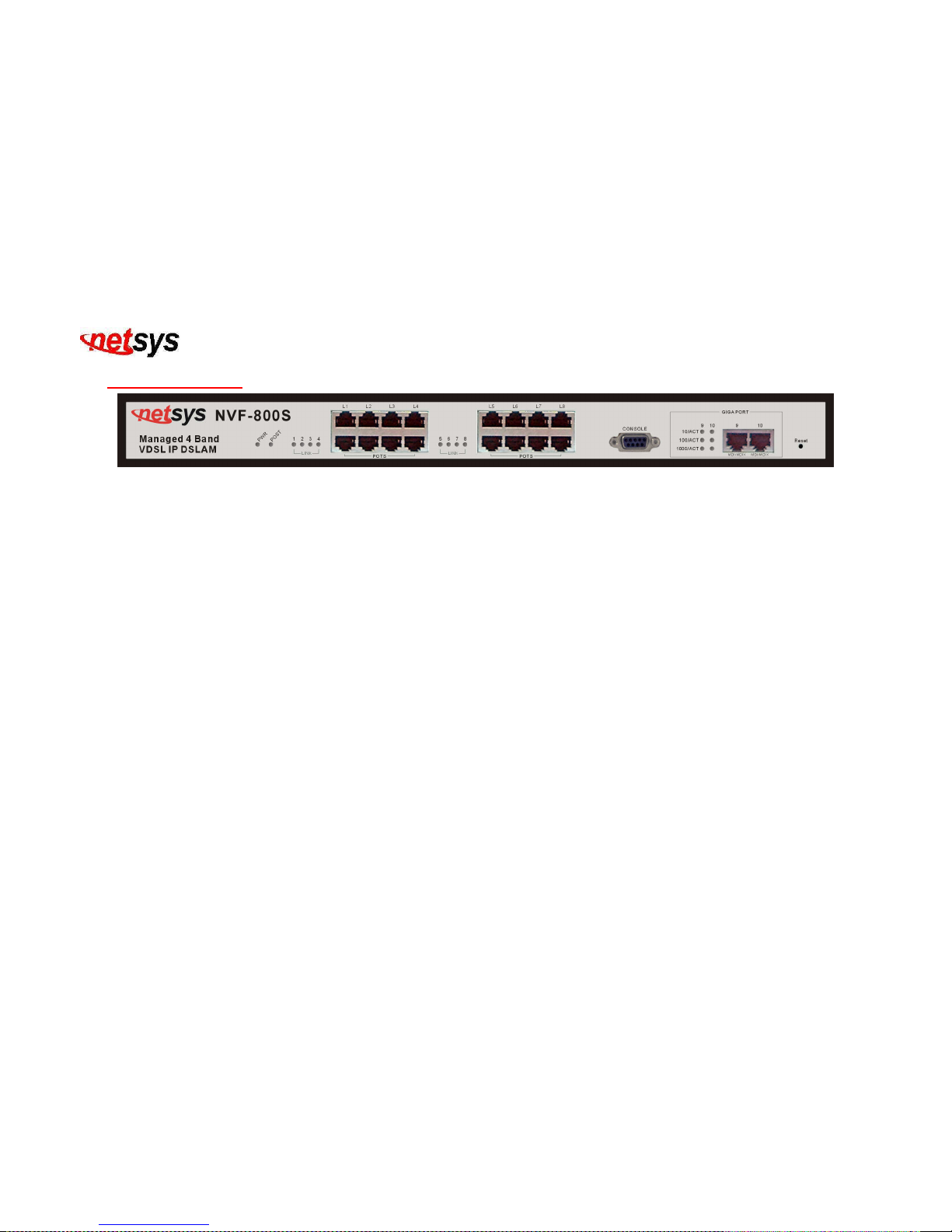
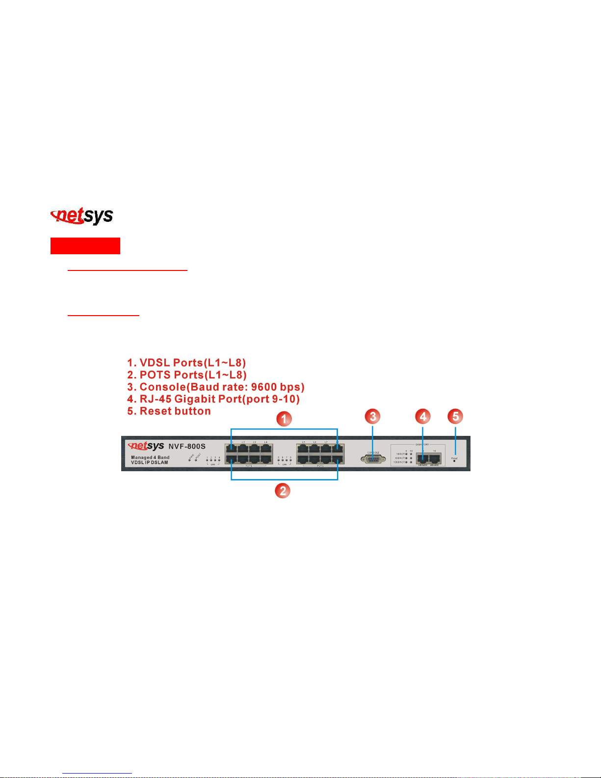
The following figure shows the front panel.(Figure 2.1)
Figure 2.1 Front Panel description
Page 19

NVF-800S 4-Band VDSL IP DSLAM USER’S MANUAL Ver_B.2
18
Front panel description:
• “PWR”: Power LED light
• “POST”: Power On Self Testing LED light
• 2 X 10/100/1000 Mbps auto-negotiation Giga Ethernet ports
• 8 X 5/15/25 Mbps VDSL ports.
• 8 X POTS/ISDN Splitter ports.
• RS-232 Console port
• Reset Button
Tip:
NVF-800S has Splitter embedded between each VDSL and POTS. It permits you to deliver broadband service on
the same lines as Plain Old Telephone Service (POTS), PBX, ISDN traffic and VDSL Signal.
Several LED indicators for monitoring the device itself, and the network status. At a quick glance of the front panel,
the user would be able to determine if the product is receiving power, if it is monitoring another IP DSLAM or if a
problem exists on the network.
Page 20
NVF-800S 4-Band VDSL IP DSLAM USER’S MANUAL Ver_B.2
19
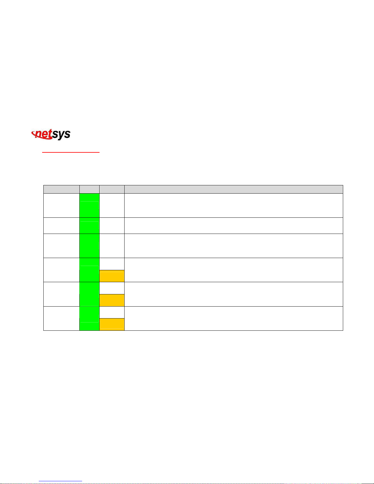
2.3 LED Indications
The following describes the function of each LED indicator. (Table 2-1)
Table 2-1 LED Indicators Description and Operation
LEDs Color Status
Descriptions
PWR
(Power LED)
Green Steady
This LED light is located at the left side on the front panel. It will light up (ON) to
show that the product is receiving power. Conversely, no light (LED OFF) means the
product is not receiving power.
POST Green Steady
POST(Power On Self Testing)POST Led will light to show system is booting now.
When system is ready the led will light off.
VDSL Link Green Steady
Each RJ11 station port on the VDSL is assigned an LED light for “Good Linkage”.
Each LED is normally OFF after the power on operation, but will light up steadily to
show good linkage.
Steady
10
LINK/ACT
Green
Blinking
Each RJ45 station port on the Ethernet is assigned an LED light for “10M Good
Linkage”. Each LED is normally OFF after the power on operation, but will light up
steadily to show good linkage. And Flashing to show data transmission.
Steady
100
LINK/ACT
Green
Blinking
Each RJ45 station port on the Ethernet is assigned an LED light for “100M Good
Linkage”. Each LED is normally OFF after the power on operation, but will light up
steadily to show good linkage. And Flashing to show data transmission.
Steady
1000
LINK/ACT
Green
Blinking
Each RJ45 station port on the Ethernet is assigned an LED light for “1000M Good
Linkage”. Each LED is normally OFF after the power on operation, but will light up
steadily to show good linkage. And Flashing to show data transmission.
Page 21
NVF-800S 4-Band VDSL IP DSLAM USER’S MANUAL Ver_B.2
20
2.4 Rear Panel
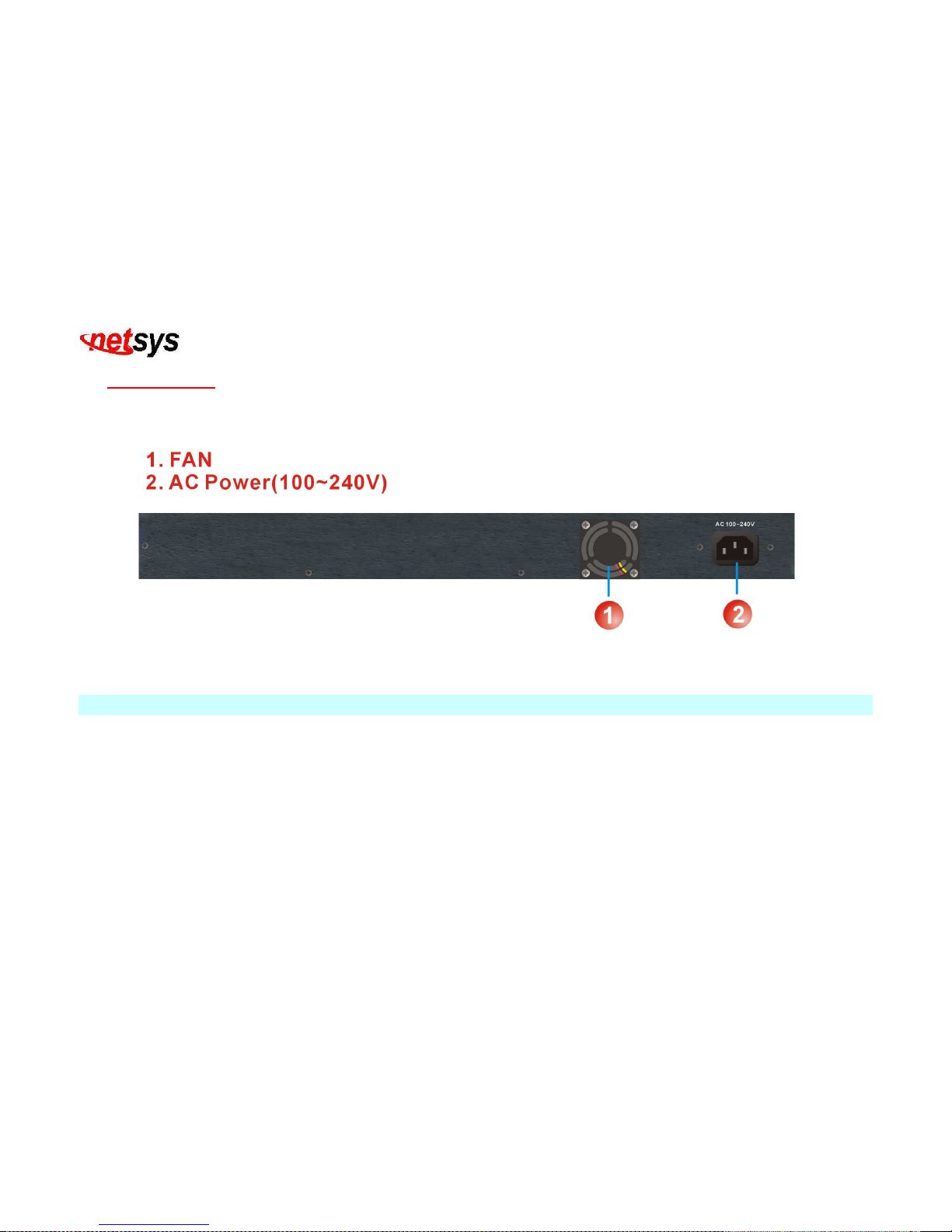
The following figure shows the rear panel.(Figure 2.2)
Figure 2.2 Rear Panel description
Note:
AC Power Socket: The power cord should be plug into this socket. The AC Socket accepts AC power 100 to 240 voltage.
Page 22

NVF-800S 4-Band VDSL IP DSLAM USER’S MANUAL Ver_B.2
21
Chapter 3. Complete Installation
3.1 Hardware Installation
This chapter describes how to install the NVF-800S. To established network connection. You may install the NVF-800S
on any level surface (table, shelf, 19 inch rack or wall mounting). However, please take note of the following minimum
site requirements before you begin.
3.2 Pre-Installation Requirements
Before you start actual hardware installation, make sure you can provide the right operating environment, including
power requirements, sufficient physical space, and proximity to other network devices that are to be connected. Verify
the following installation requirement:
• Power requirements: AC 85V to 265 V at 50 to 60 Hz.
Tip:
The Switching power supply automatically adjusts to the input voltage level.
• The NVF-800S should be located in a cool dry place, with at least 10cm/4in of space at the front and back for
ventilation.
• Place the NVF-800S away from direct sunlight, heat sources, or areas with a high amount of electromagnetic
interference.
• Check if network cables and connectors needed for installation are available.
• Do Not install phone lines strapped together with AC power lines, or telephone office line with voice signal.
• Avoid installing this device with radio amplifying station nearby or transformer station nearby.
• Please note NVF-800S internal splitter, can pass through voice spectrum is 0KHz ~ 630KHz.
Page 23

NVF-800S 4-Band VDSL IP DSLAM USER’S MANUAL Ver_B.2
22
3.3 General Rules
Before making any connections to the NVF-800S, note the following rules:
Ethernet Port (RJ-45)
All network connections to the NVF-800S Ethernet port must be made using Category 5 UTP for 100Mbps and
Category 3, 4 UTP for 10Mbps. No more than 100 meters (about 333 feet) of cabling may be use between
NVF-800S or with HUB or an end node.
VDSL Port (RJ-11)
All home network connections to the VDSL Port must use 18 ~ 26 gauge with twisted pair phone wiring.
We do not recommend using 28 Gauge or above phone line.
3.4 NVF-800S Connections
The NVF-800S has 2 x 10/100/1000Mbps Ethernet ports which support connection to 10/100/1000Mbps Giga Ethernet.
The NVF-800S also supports full or half-duplex operation and the transmission mode is auto-negotiation. Therefore,
the devices attached to these ports must support auto-negotiation unless they will always operate at half duplex. If
transmissions must run at full duplex, but the attached device does not support auto-negotiation then one should
upgrade this device to a newer version that supports auto-negotiation and auto-crossover (MDI/MDIX).
3.5 “MDI-X” Station Port Connections
1. Connect the port “9 or 10” on the NVF-800S to any device that uses a standard network interface such as a Cable
bridge, ADSL bridge, Ethernet Switch, workstation, server or to a network interconnection device such as a bridge
or bridge, but depends on the port type implemented.
2. Prepare the network devices one wish to connect. Make sure one have installed suitable VDSL Bridge before
Page 24

NVF-800S 4-Band VDSL IP DSLAM USER’S MANUAL Ver_B.2
23
making a connection to any of the NVF-800S (L1-L8) station ports. Prepare also 18 ~ 26 gauge twisted pair phone
wiring with RJ-45 plugs at both ends.
3. Connect one end of the cable to the RJ-45 port of the Home Access network adapter and the other end to any
available (1 ~ 8) station port on the VDSL. Every port supports 5/15/25Mbps connections. When inserting an RJ-45
plug, be sure the tab on the plug clicks into position to ensure that it is properly seated.
Caution:
Do not plug a RJ-11 phone jack connector into the Ethernet port (RJ-45 port). This may damage the HPNA. Instead,
use only twisted-pair cables with RJ-45 connectors that conform the FCC standards.
Notes:
1. Be sure each twisted-pair cable (RJ-45) is not over by 100 meters (328 feet).
2. RJ-11 port use 18 ~ 26 gauge phone wiring, 28 gauge or above is not recommended.
3. We advise using Category 5 cable for Cable Modem or router connections or to attach to any high bandwidth device to
avoid any confusion or inconvenience.
3.6 “MDI” Port (TX) Connections
Prepare straight through shielded or unshielded twisted pair cables with RJ-45 plugs on both ends. Use 100Ω
Category 5 cable for connections. Connect one end of the cable to port “9 or 10” of the NVF-800S and the other end to
a standard RJ-45 station port on cable bridge, ADSL bridge, wireless bridge, etc. When inserting an RJ-45 plug, be
sure the tab on the plug clicks into position to ensure that it is properly seated.
Note:
Make sure the length of twisted-pair cable is not over by 100 meters (328 feet).
Page 25
NVF-800S 4-Band VDSL IP DSLAM USER’S MANUAL Ver_B.2
24
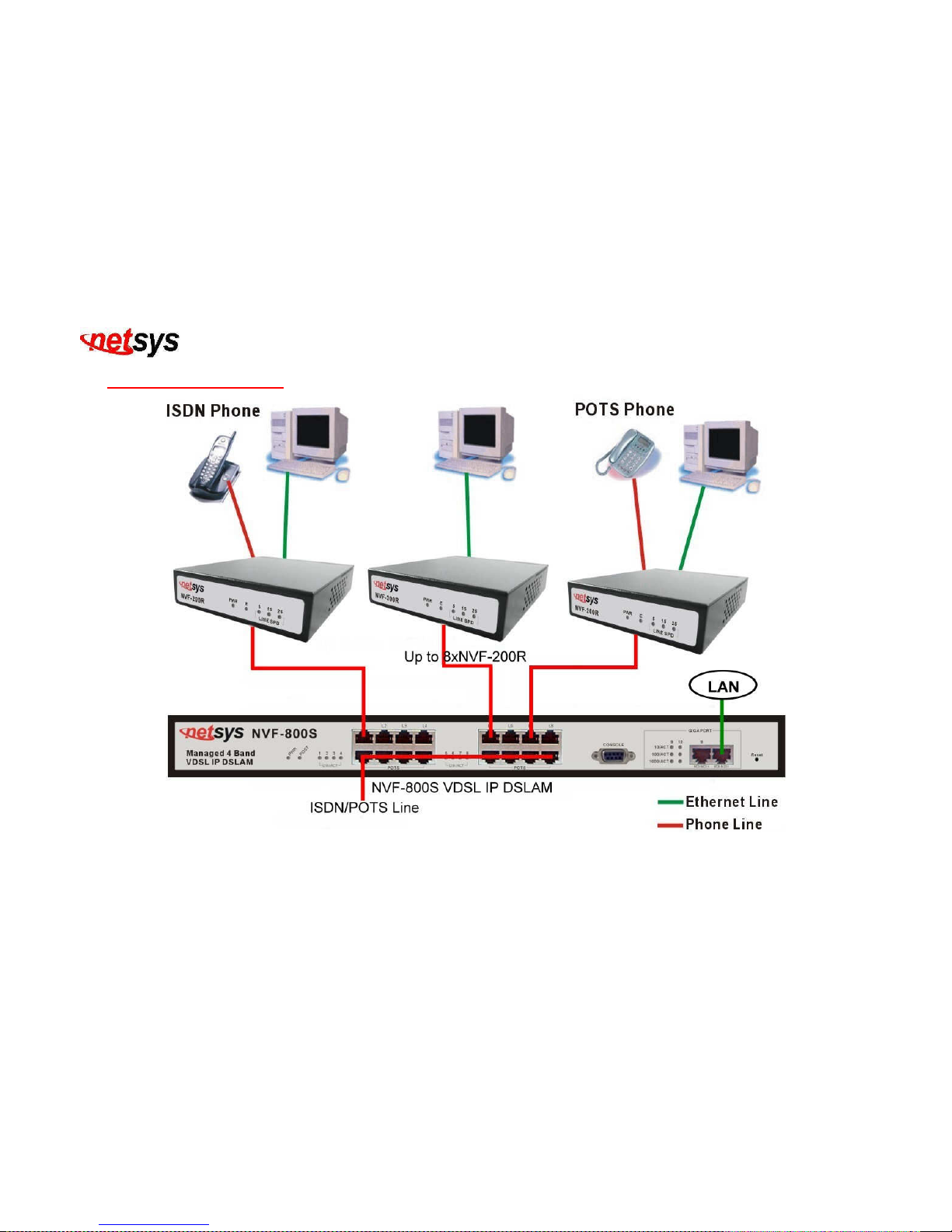
3.7 Basic Configuration
Figure 3.1 NVF-800S Basic Application Diagram
Page 26
NVF-800S 4-Band VDSL IP DSLAM USER’S MANUAL Ver_B.2
25
Chapter 4. Management Configuration
4.1 In-Band Management
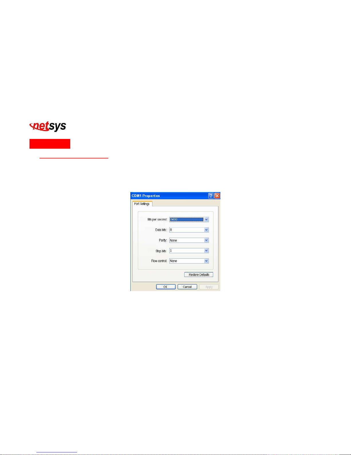
Console port (RS-232) Configuration
Configure the unit with the local serial console port, if one of the RJ11 port is not in use, you can disable it by connecting a
notebook computer to the RS-232 port, then boot with windows OS system and launch “Hyperterminal” program into
terminal window. Setup steps are as follow: (Figure 4.1)
Figure 4.1 COM1 Properties
1. Set “Bits per second” at 9600 to the content window.
2. Set “Flow control” at None
Page 27
NVF-800S 4-Band VDSL IP DSLAM USER’S MANUAL Ver_B.2
26
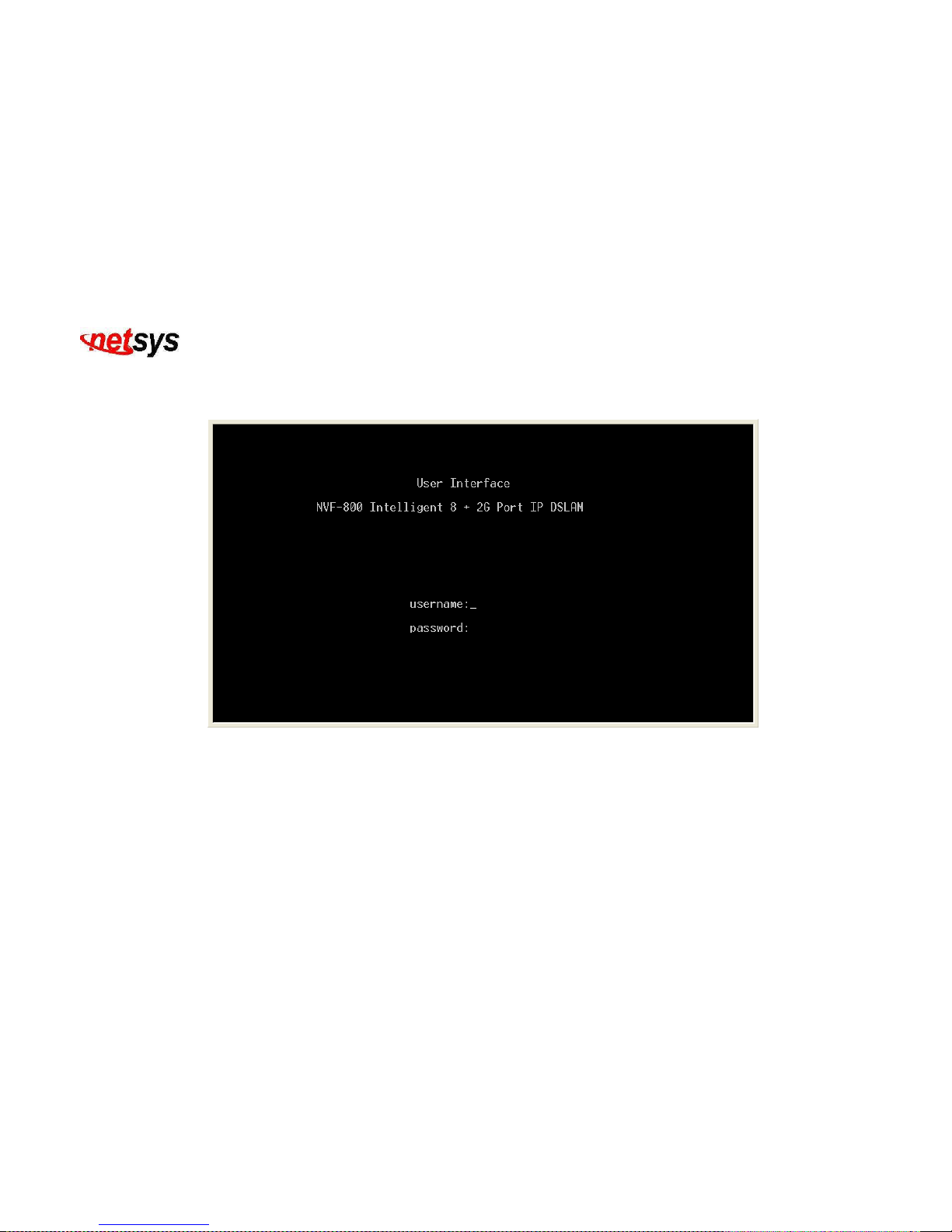
3. Connects PC with the NVF-800S, you will find login manual window on the screen then enter
Login name:”admin” ; password:”123”. (
Figure 4.2)
Figure 4.2 User Interface
Page 28
NVF-800S 4-Band VDSL IP DSLAM USER’S MANUAL Ver_B.2
27
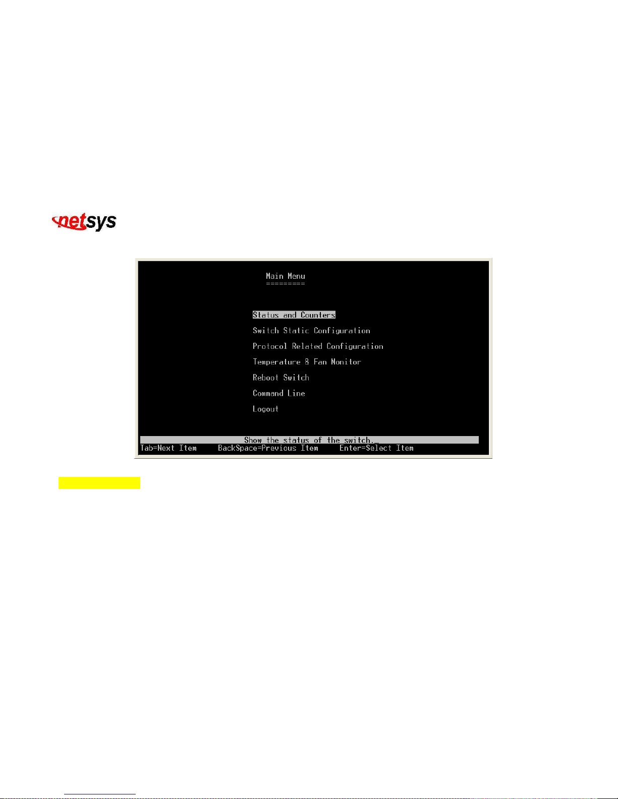
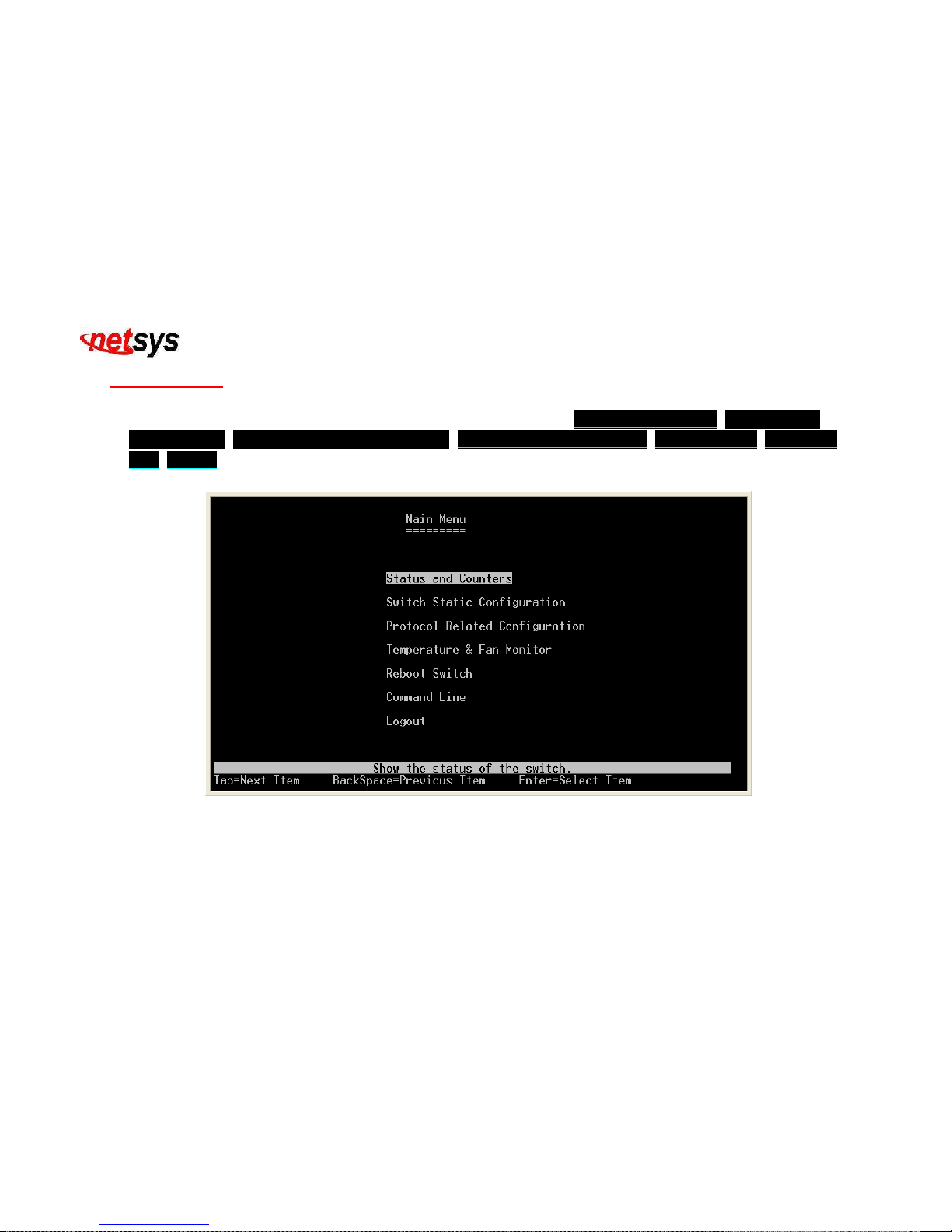
4. This is the main menu screen: (Figure 4.3)
Figure 4.3 Main Menu
Operation Button:
Tab=Next Item;
Backspace=Previous Item;
Enter=Select Item
Page 29
NVF-800S 4-Band VDSL IP DSLAM USER’S MANUAL Ver_B.2
28
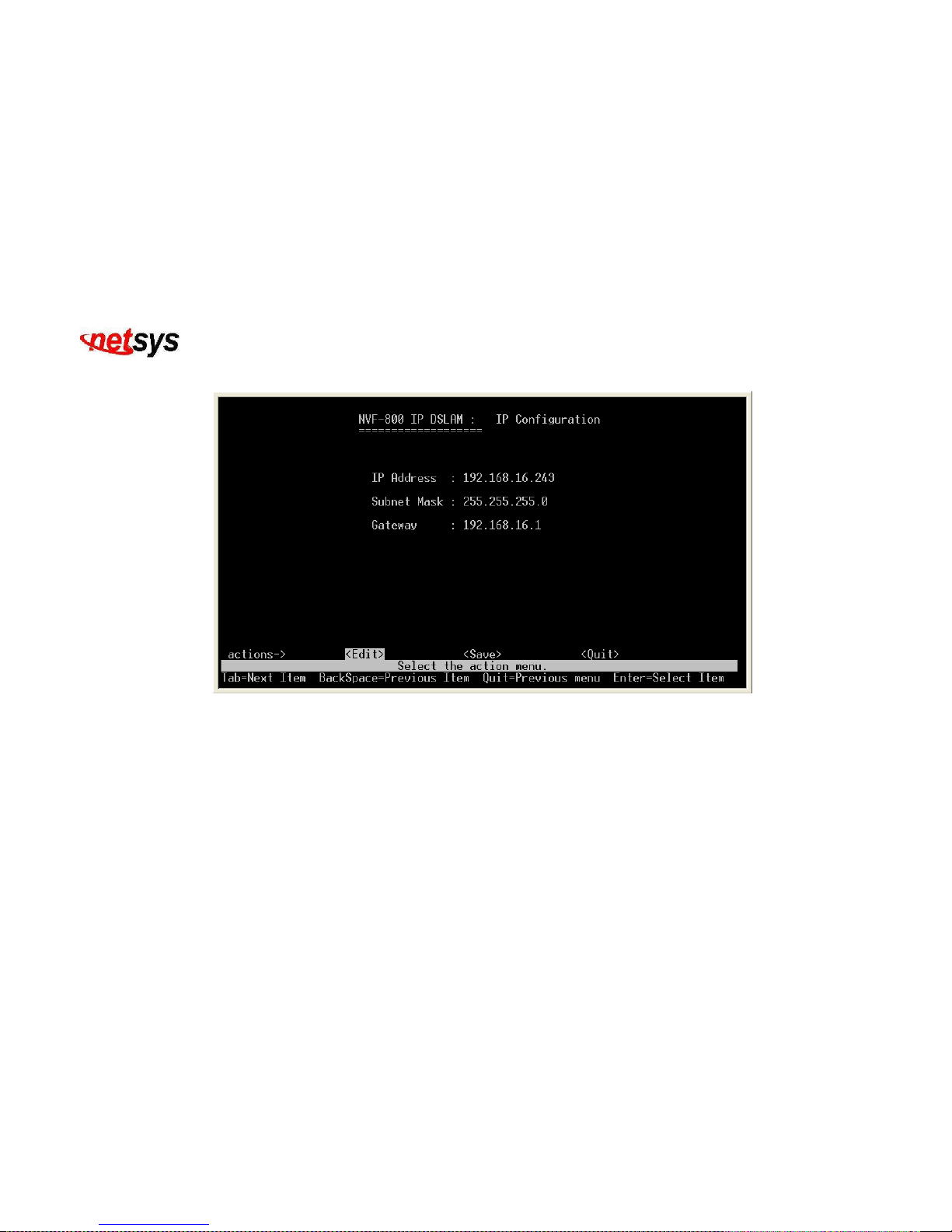
Change the IP Configuration, enter the IP configuration page and follow these steps: (Figure 4.4)
Figure 4.4 IP Configuraiton
1. Choose Edit item to Change IP address, Subnet Mask and Gateway.
2. Use CTRL+A button to back actions choice.
3. Choose Save item to save change and back to System Configuration page.
4. Choose Previous Menu item to quit System Configuration page.
5. Choose Main Menu item to quit NVF-800S Configuration page and back to Main Manual.
6. Choose Reboot NVF-800S item.
7. Choose Restart item to reboot your NVF-800S.
Page 30
NVF-800S 4-Band VDSL IP DSLAM USER’S MANUAL Ver_B.2
29
4.1.1 Main Menu
There is an easy Setup for end users at the setup of NVF-800S with Status and Counters, Switch Static
Configuration, Protocol Related Configuration, Temperature & Fan Monitor, Reboot Switch, Command
Line, Logout for more detail configurations. (Figure 4.5)
Figure 4.5 Main Menu introduction
Page 31
NVF-800S 4-Band VDSL IP DSLAM USER’S MANUAL Ver_B.2
30
4.1.1.1 Status and Counters
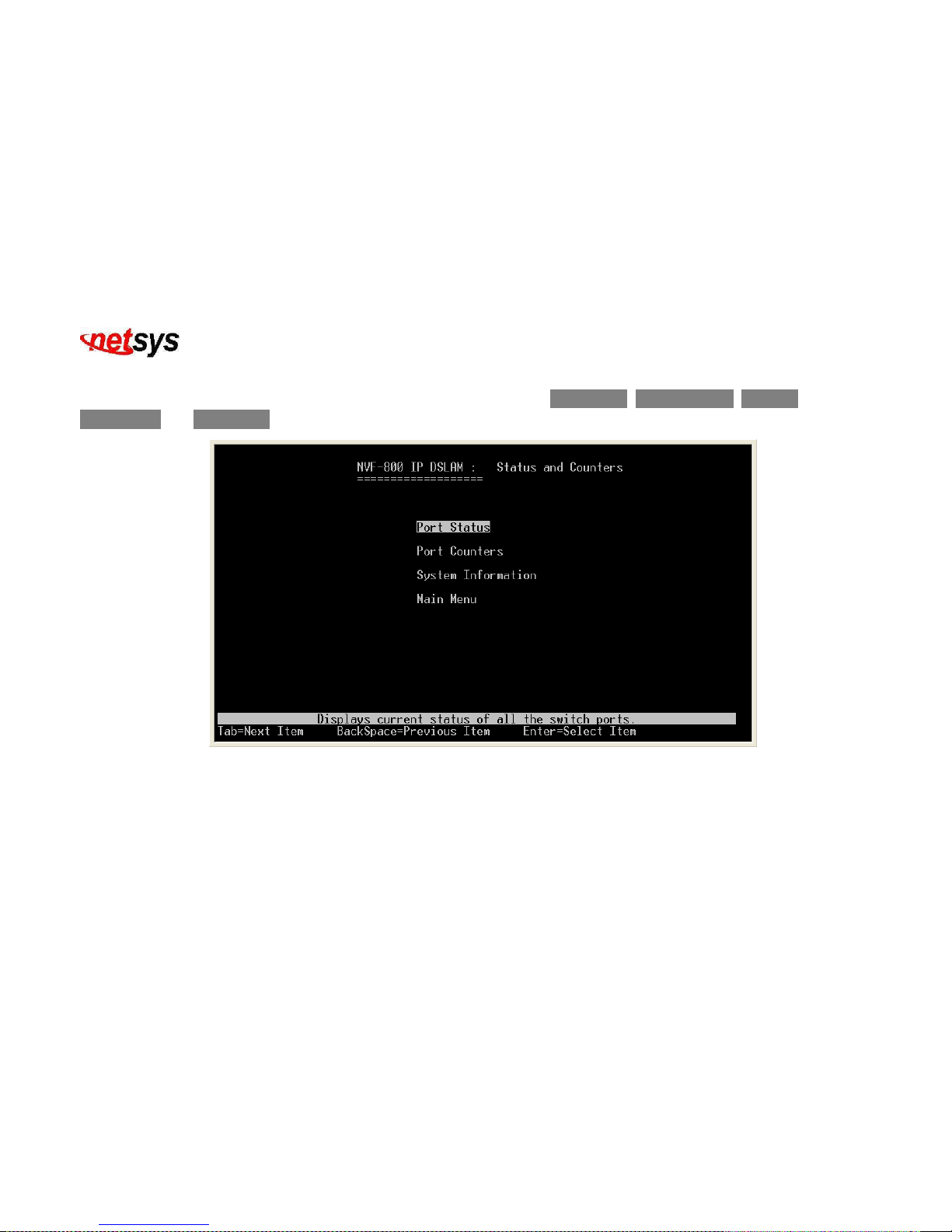
Select the “Status and Counters”. The menu below includes the sub-menus of Port Status, Port Counters, System
Information and Main Menu.(Figure 4.6)
Figure 4.6 Status and Counters
Page 32
NVF-800S 4-Band VDSL IP DSLAM USER’S MANUAL Ver_B.2
31
4.1.1.1.1 Port Status
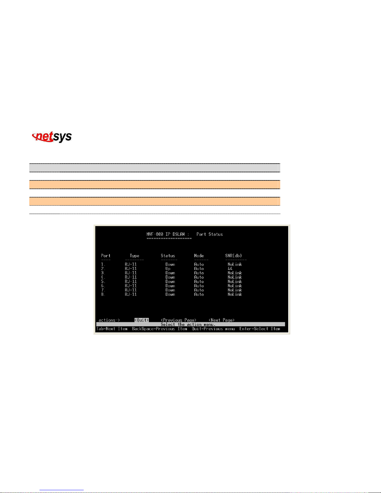
Displays the current status of all switch ports. (Figure 4.7)
Item Description
Port:
Shows the port number of NVF-800S VDSL IP DSLAM.
Type:
Shows the media type of the port’s device.
Status:
Shows the condition of the port if it is up or down.
Mode:
Shows at what mode is the port set. It can either be Auto, 5M, 15M or 25Mbps.
SNR(dB):
Shows if the NVF-800S VDSL IP DSLAM is link or not and the value of SNR in dB.
Figure 4.7 Port Status
Page 33
NVF-800S 4-Band VDSL IP DSLAM USER’S MANUAL Ver_B.2
32
4.1.1.1.2 Port Counters
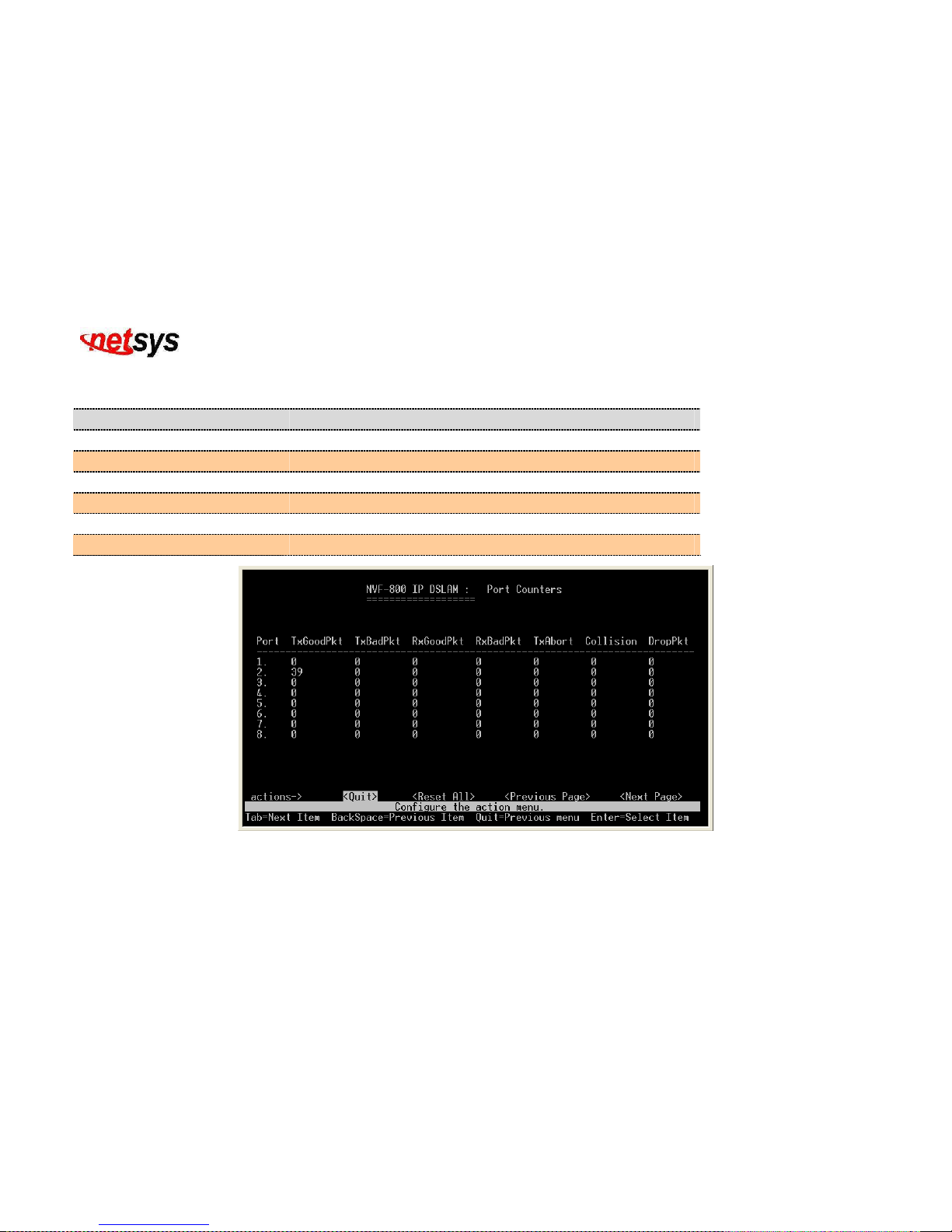
Displays a summary of network activity. (Figure 4.8)
Item Description
Port:
Shows the port number of NVF-800S VDSL IP DSLAM.
TxGoodPkt and RxGoodPkt:
Shows the values of good packets transmitted and received.
TxBadPkt and RxBadPkt:
Shows the values of bad packets transmitted and received.
TxAbort:
Shows the values of the aborted packets being transmitted.
Collision:
Shows the values of packets collisions.
DropPkt:
Shows the values of packet being drop.
Figure 4.8 Port Counters
Page 34

NVF-800S 4-Band VDSL IP DSLAM USER’S MANUAL Ver_B.2
33
Tip:
Packet Collision: In a network, when two or more stations attempt to transmit a packet across the network at the same
time, a packet collision occurs. This is not uncommon in a shared medium such as an Ethernet that has many computers
in the same network segment. When a packet collision occurs, the packets are either discarded or sent back to their
originating stations and then retransmitted in a timed sequence to avoid further collision. Packet collisions can result in
the loss of packet integrity or can impede the performance of a network.
Page 35
NVF-800S 4-Band VDSL IP DSLAM USER’S MANUAL Ver_B.2
34
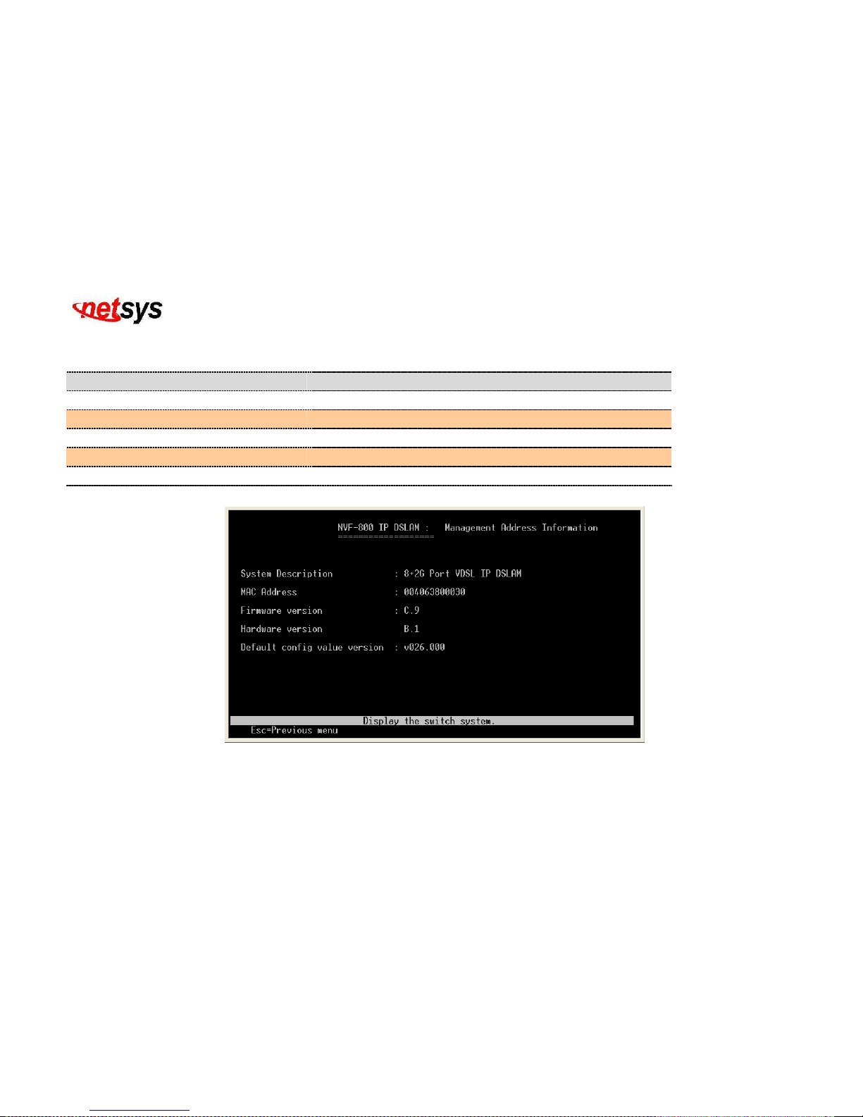
4.1.1.1.3 System Information
Display the switch system. (Figure 4.9)
Item Description
System Description:
Shows the full description of NVF-800S VDSL IP DSLAM
MAC Address:
Shows the unique MAC address of the device.
Firmware version:
Shows the firmware version being used by the device.
Hardware version:
Shows the hardware version being used by the device.
Default configuration value version:
Shows the version of the default configuration being used.
Figure 4.9 Management Address Information
Page 36
NVF-800S 4-Band VDSL IP DSLAM USER’S MANUAL Ver_B.2
35
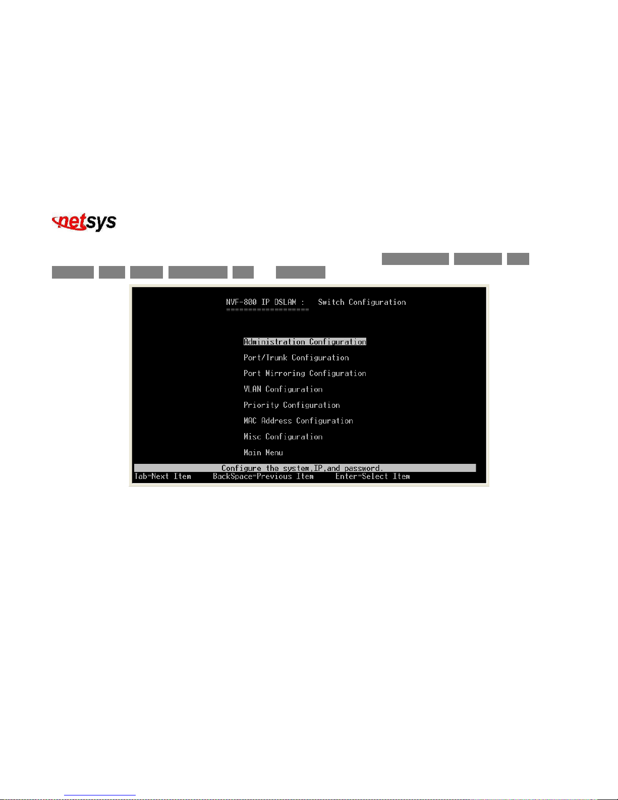
4.1.1.2 Switch Static Configuration
Select the “Switch Static Configuration”. The menu below includes the sub-menus of Administration, Port/Trunk, Port
Mirroring, VLAN, Priority, Mac Address, Misc and Main Menu. (Figure 4.10)
Figure 4.10 Switch Configuration
Page 37
NVF-800S 4-Band VDSL IP DSLAM USER’S MANUAL Ver_B.2
36
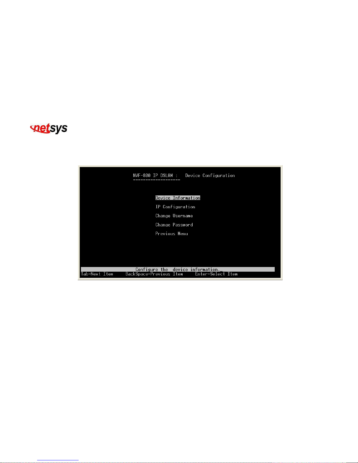
4.1.1.2.1 Administration Configuration
Select the “Administration Configuration”. The menu below includes the sub-menus of Device Information, IP configuration,
Change Username and Change Password. Please configure the Administration items as follows. (Figure 4.11)
Figure 4.11 Administration Configuration
Page 38
NVF-800S 4-Band VDSL IP DSLAM USER’S MANUAL Ver_B.2
37
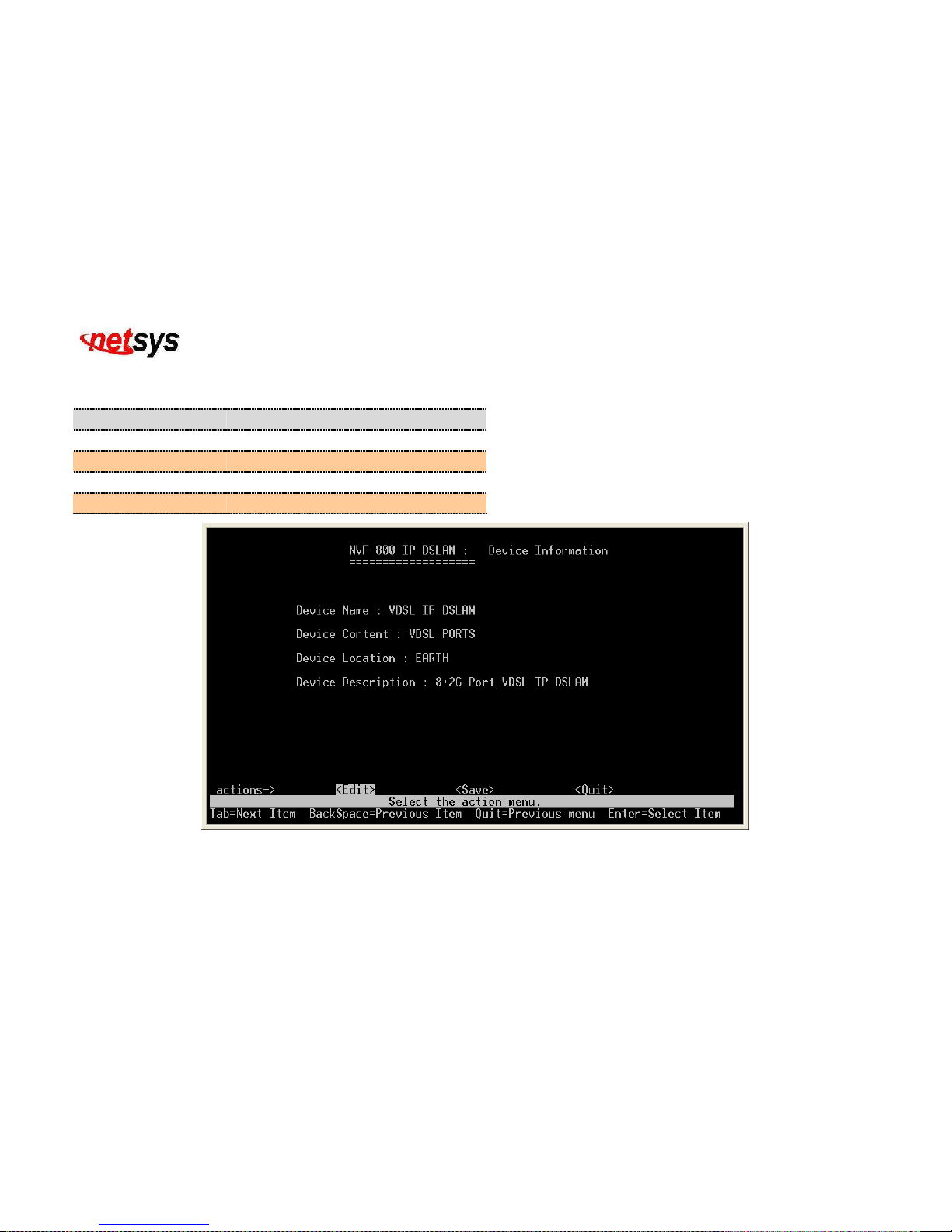
4.1.1.2.1.1 Device Configuration
Configure the device information, you can edit and create your own name. (Figure 4.12)
Item Description
Device Name:
Shows the whole device name.
Device Content:
Shows the content of the device.
Device Location:
Shows the location of the device.
Device Description:
Shows the description of the device.
Figure 4.12 Device Information
Page 39
NVF-800S 4-Band VDSL IP DSLAM USER’S MANUAL Ver_B.2
38
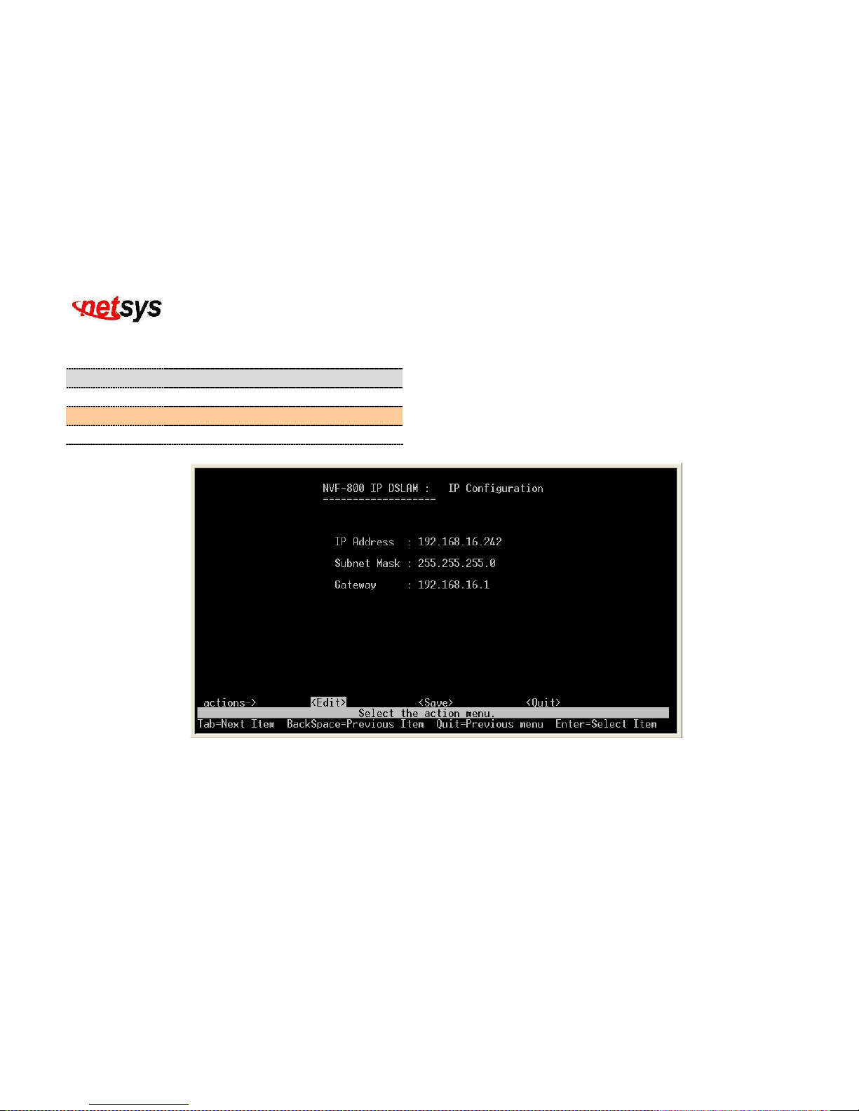
4.1.1.2.1.2 IP Configuration
Configure the IP(Internet Protocol) information. (Figure 4.13)
Item Description
IP Addr
ess:
Shows the IP address of the device.
Subnet Mask:
Shows the subnet mask of the device.
Gateway:
Shows the gateway of the device.
Figure 4.13 IP Configuration
Page 40
NVF-800S 4-Band VDSL IP DSLAM USER’S MANUAL Ver_B.2
39
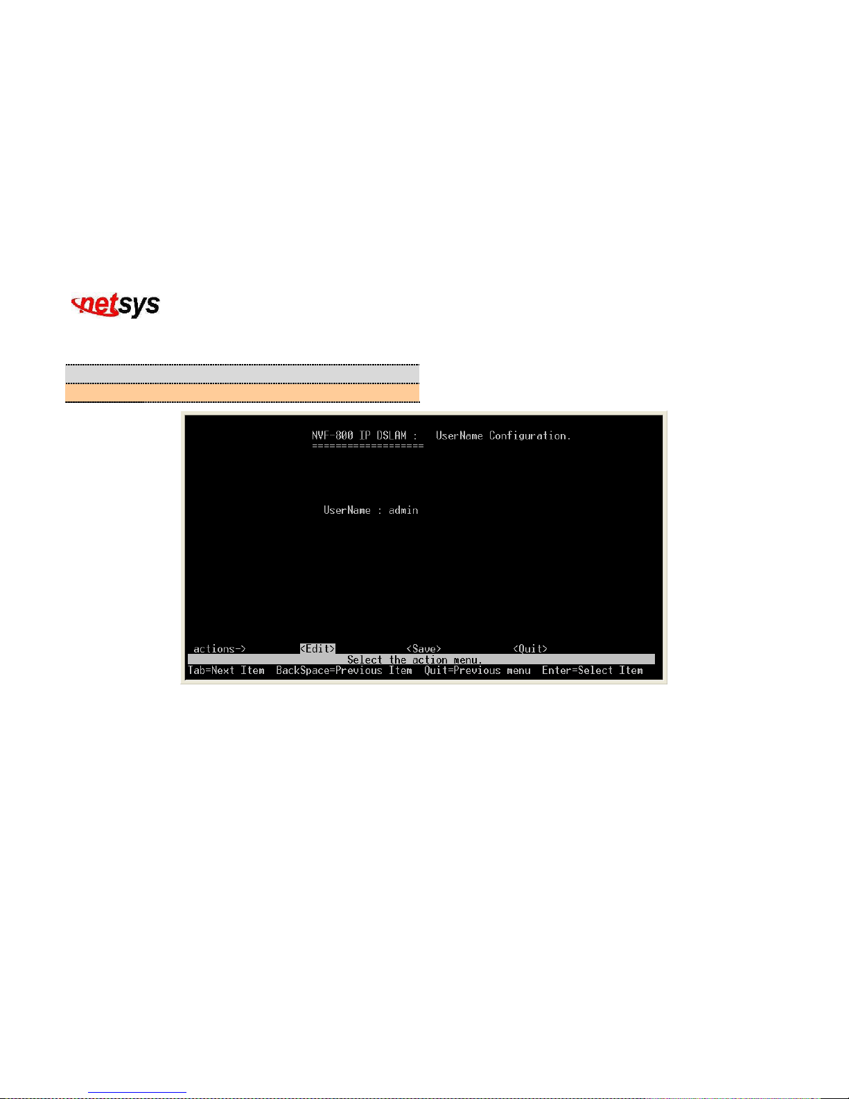
4.1.1.2.1.3 Change Username
Item Description
Username:
Shows and configure the current username. (Figure 4.14)
Figure 4.14 User Name Configuration
Page 41
NVF-800S 4-Band VDSL IP DSLAM USER’S MANUAL Ver_B.2
40
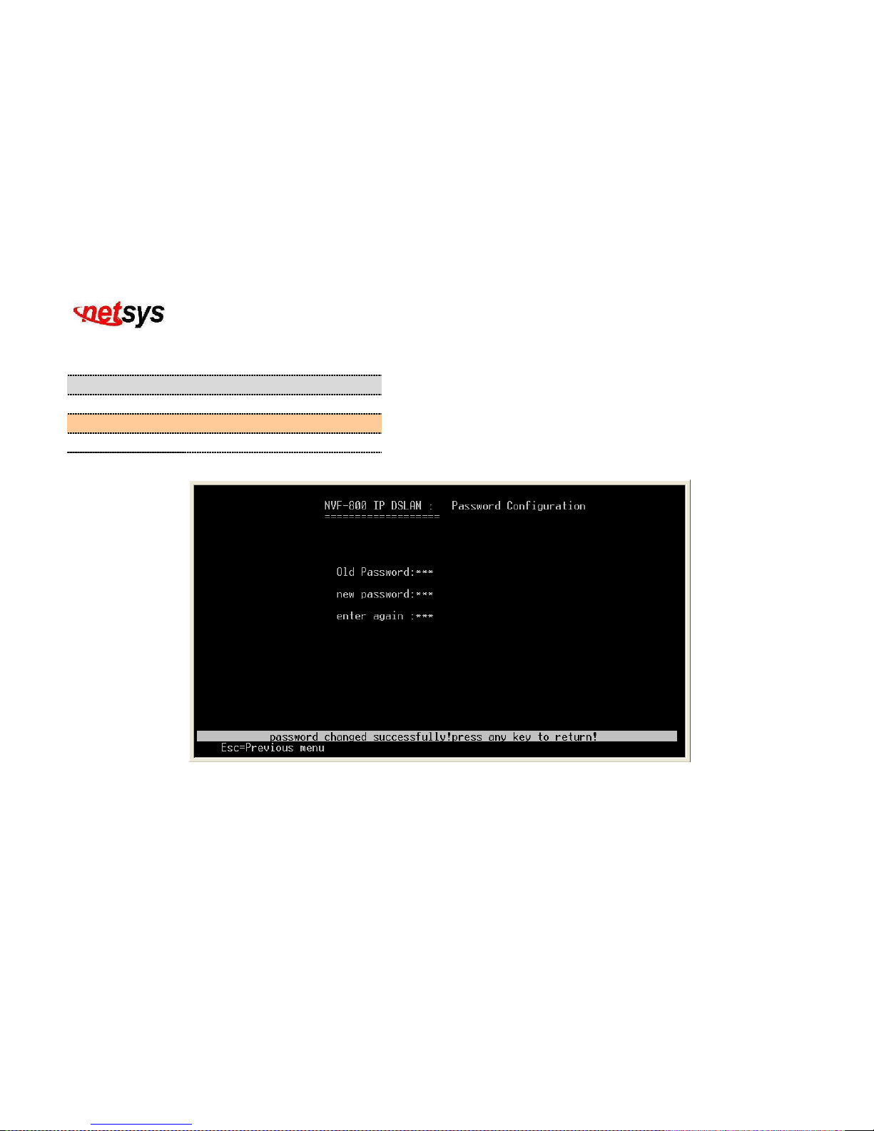
4.1.1.2.1.4 Change Password
Configure the password, type the numbers will be masked. (Figure 4.15)
Item Description
Old Password:
Type the old password.
New Password:
Type the new password.
Enter again:
Type the new password again.
Figure 4.15 Password Configuration
Page 42
NVF-800S 4-Band VDSL IP DSLAM USER’S MANUAL Ver_B.2
41
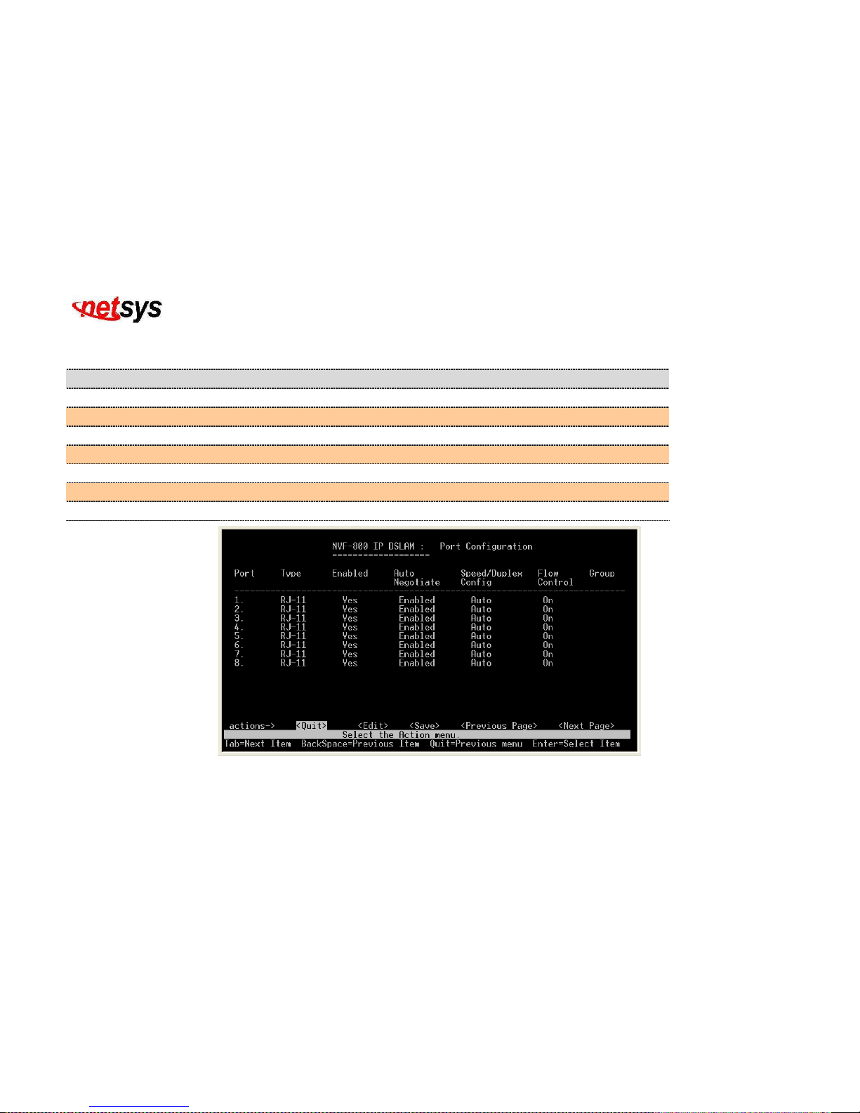
4.1.1.2.2 Port/Trunk Configuration
Display or change port/trunk configuration. (Figure 4.16)
Item Description
Port:
Shows the port number of NVF-800S VDSL IP DSLAM.
Type:
Shows the media type of the port’s device.
Enabled:
Shows and configure if the port is enabled or not.
Auto Negotiate:
Shows and configure if the port can either auto negotiate or not.
Speed/Duplex Config:
Shows and configure the speed of each port if it is Auto/5M/15M/25Mbps.
Flow Control:
Shows if the flow control on each port is either active or not.
Group:
Shows the group trunking of each port if it is None/trk1/trk2/trk3/trk4.
Figure 4.16 Port Configuration
Page 43
NVF-800S 4-Band VDSL IP DSLAM USER’S MANUAL Ver_B.2
42
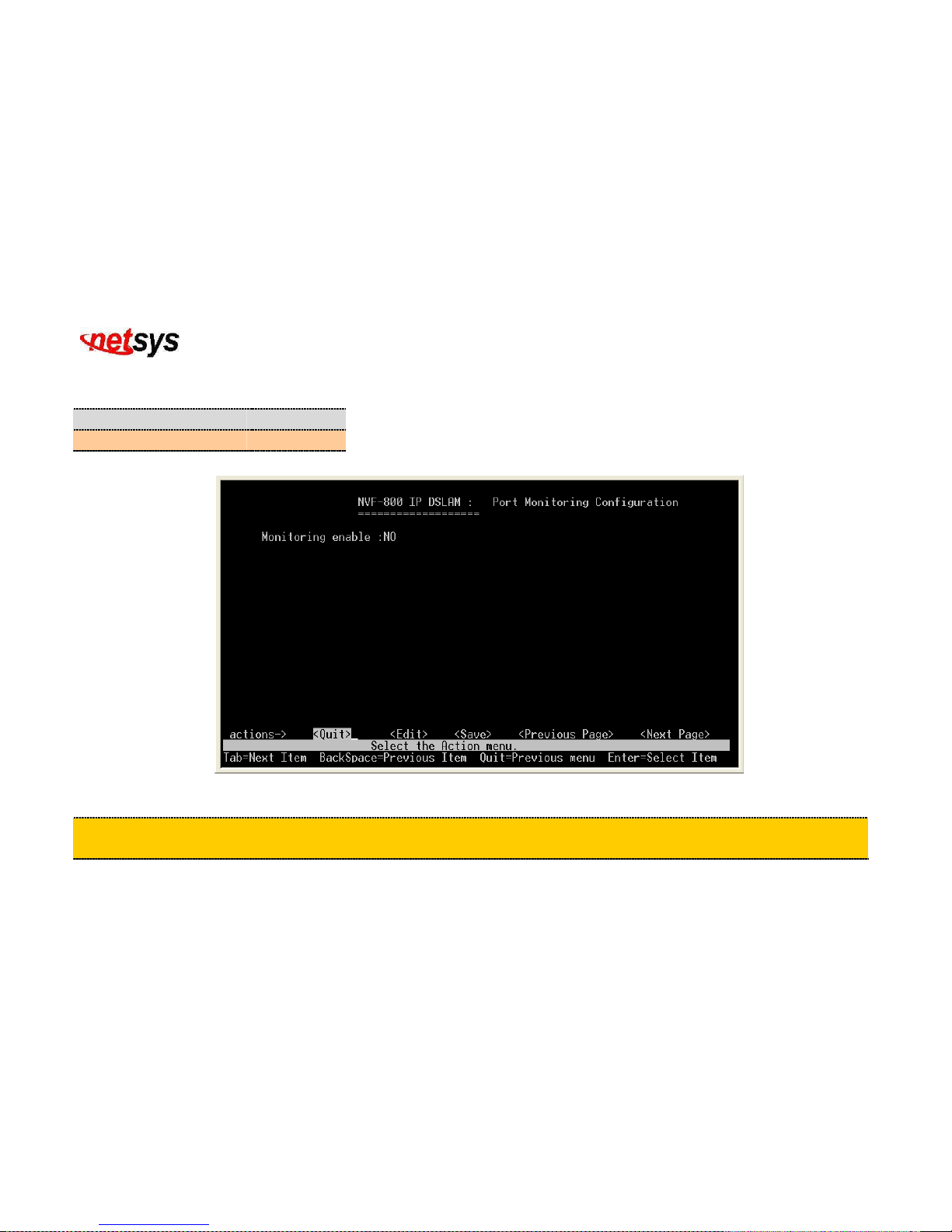
4.1.1.2.3 Port Mirroring Configuration
Display or change port mirror configuration. (Figure 4.17)
Item Description
Monitoring Enable:
NO
Default monitoring enable is NO.
Figure 4.17 Port Monitoring Configuration(Disable)
Tip:
This function can special monitor client side as duplicate mail, Http…..etc, but need to be used with the application
software(i.e. sniffer software).
Page 44
NVF-800S 4-Band VDSL IP DSLAM USER’S MANUAL Ver_B.2
43
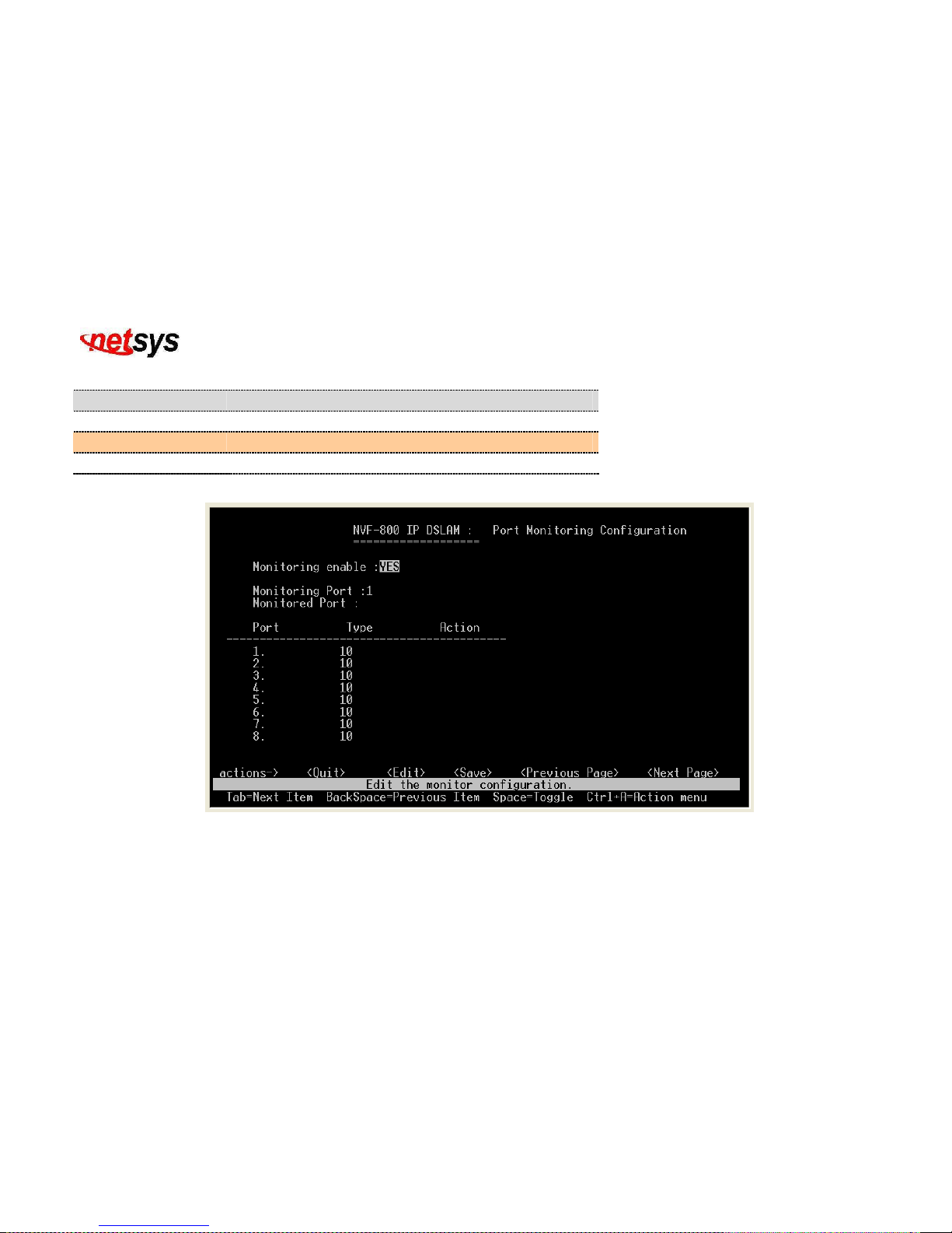
Item Description
Monitoring Enable:
YES
Monitoring Port:
Shows the monitoring port selection from port 1 to 10.
Action:
Show the action of the monitoring if it is Tx/Rx/Both.
(Figure 4.18)
Figure 4.18 Port Monitoring Configuration(Enable)
Page 45
NVF-800S 4-Band VDSL IP DSLAM USER’S MANUAL Ver_B.2
44
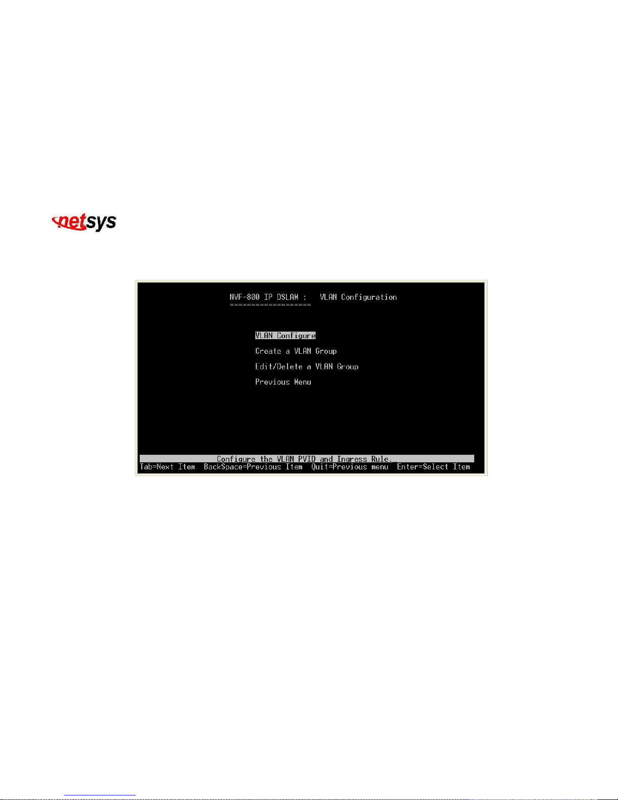
4.1.1.2.4 VLAN Configuration
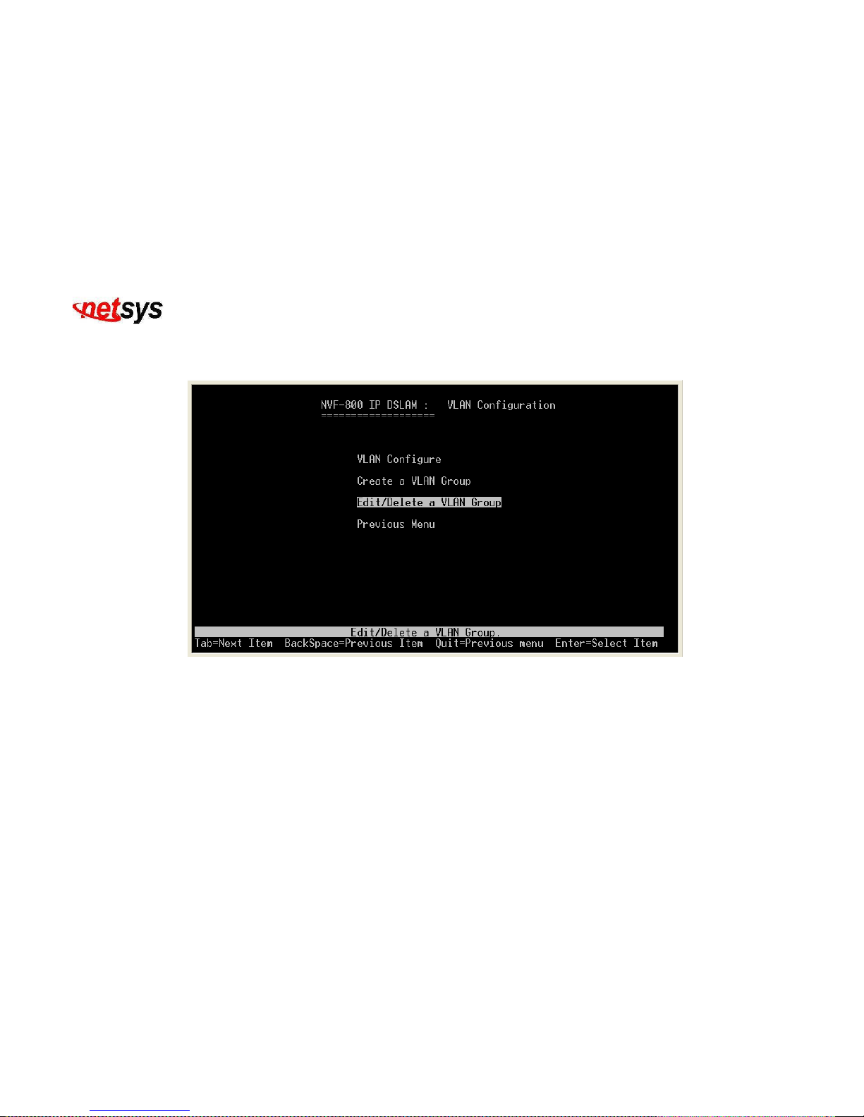
Select the “VLAN Configuration”. The menu below includes the sub-menus of VLAN Configure, Create a VLAN Group,
Edit/Delete a VLAN Group. Display or change VLAN (Virtual Local Area Network) configuration. (Figure 4.19)
Figure 4.19 VLAN Configure
Page 46
NVF-800S 4-Band VDSL IP DSLAM USER’S MANUAL Ver_B.2
45
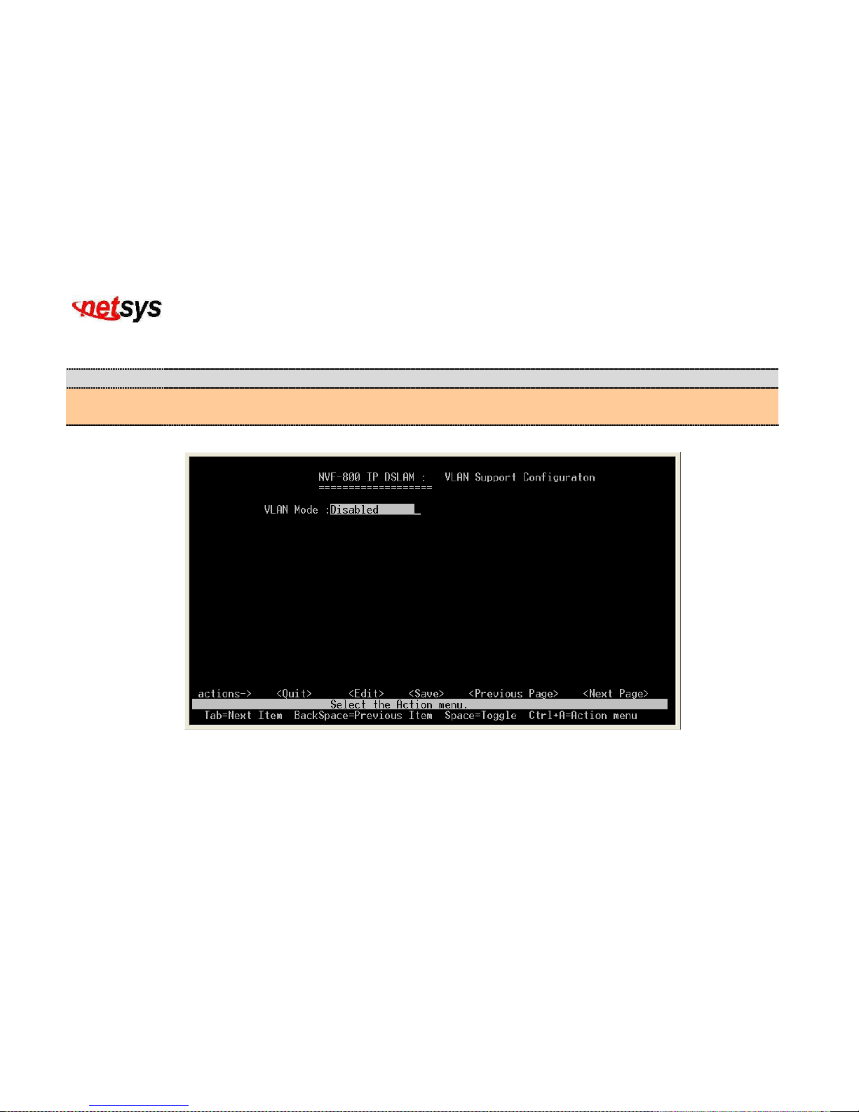
4.1.1.2.4.1 VLAN Configure
Configure the VLAN PVID and Ingress Rule.
Item Description
VLAN Mode:
User can choose from 4 VLAN modes, respectively, 802.1Q, 802.1Q with GVRP, Port Based and
Disable. Default VLAN mode is disabled.
VLAN Mode: Disabled (Figure 4.20)
Figure 4.20 VLAN Mode: Disable
Page 47
NVF-800S 4-Band VDSL IP DSLAM USER’S MANUAL Ver_B.2
46
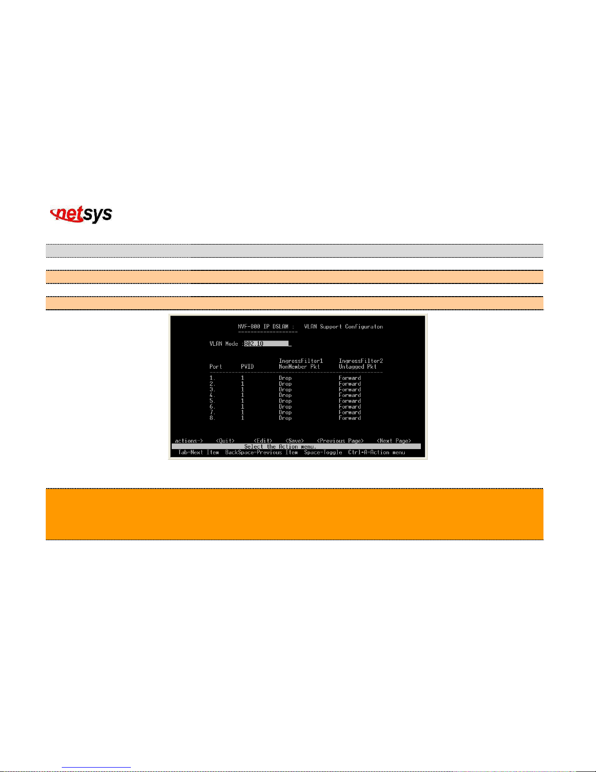
VLAN Mode: 802.1Q (Figure 4.21)
Item Description
Port:
Shows the port of NVF-800S VDSL IP DSLAM.
PVID:
Shows the PVID value. Valid range is from 1 to 4094.
IngressFilter1 NonMember Pkt:
Shows the packet being forward only packets with VID matching this port's configured VID
IngressFilter2 Untagged Pkt:
Shows the packet being drop Untagged Frame
Figure 4.21 VLAN Mode: 802.1Q
Tip:
PVID: Sets the Port VLAN ID that will be assigned to untagged traffic on a given port. For example, if port 1's Default PVID is 100,
all untagged packets on port 1 will belong to VLAN 100. The default setting for all ports is VID 1.
This feature is useful for accommodating devices that you want to participate in the VLAN but that don't support tagging. Only one
untagged VLAN is allowed per port.
Page 48
NVF-800S 4-Band VDSL IP DSLAM USER’S MANUAL Ver_B.2
47
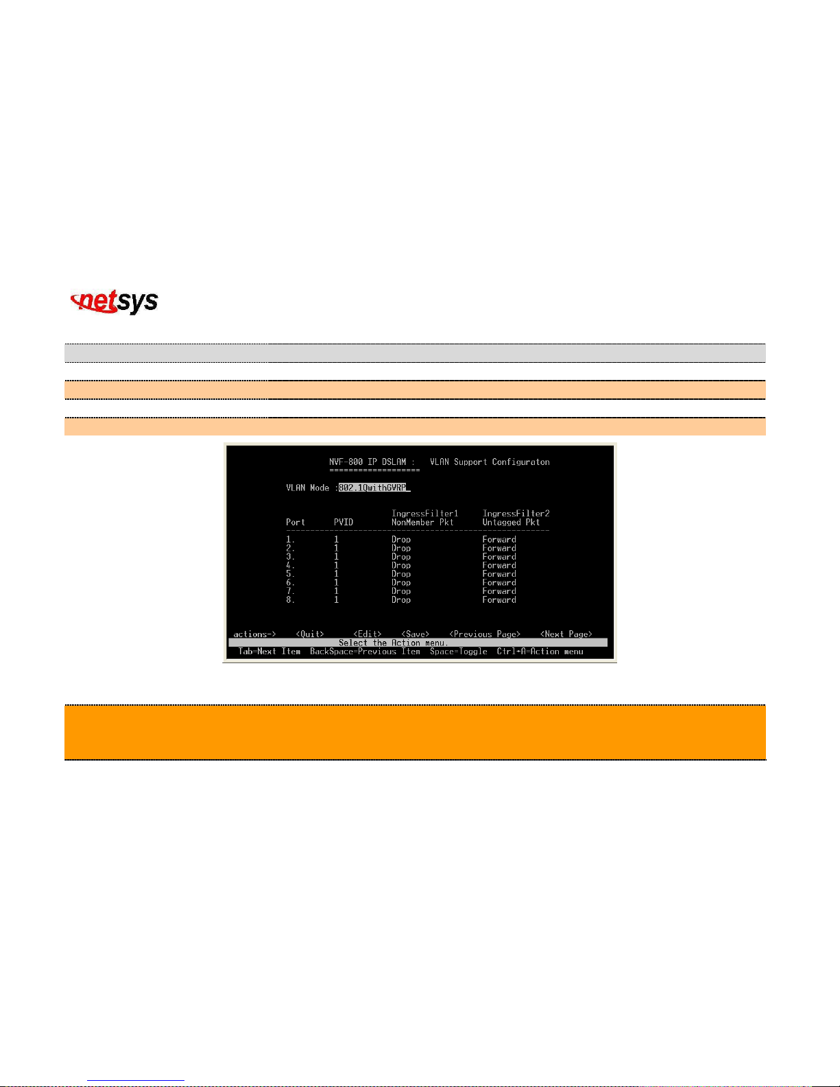
VLAN Mode: 802.1Q with GVRP(Figure 4.22)
Item Description
Port:
Shows the port number of NVF-800S VDSL IP DSLAM.
PVID:
Shows the PVID value. Valid range is from 1 to 4094.
IngressFilter1 NonMember Pkt:
Shows the packet being forward only packets with VID matching this port's configured VID.
IngressFilter2 Untagged Pkt:
Shows the packet being drop Untagged Frame.
Figure 4.22 VLAN Mode: 802.1Q with GVRP
Tip:
GVRP (GARP [Generic Attribute Registration Protocol] VLAN Registration Protocol): GVRP allows automatic VLAN
configuration between the switch and nodes. If the switch is connected to a device with GVRP enabled, you can send a GVRP
request using the VID of a VLAN defined on the switch, the switch will automatically add that device to the existing VLAN.
Page 49
NVF-800S 4-Band VDSL IP DSLAM USER’S MANUAL Ver_B.2
48
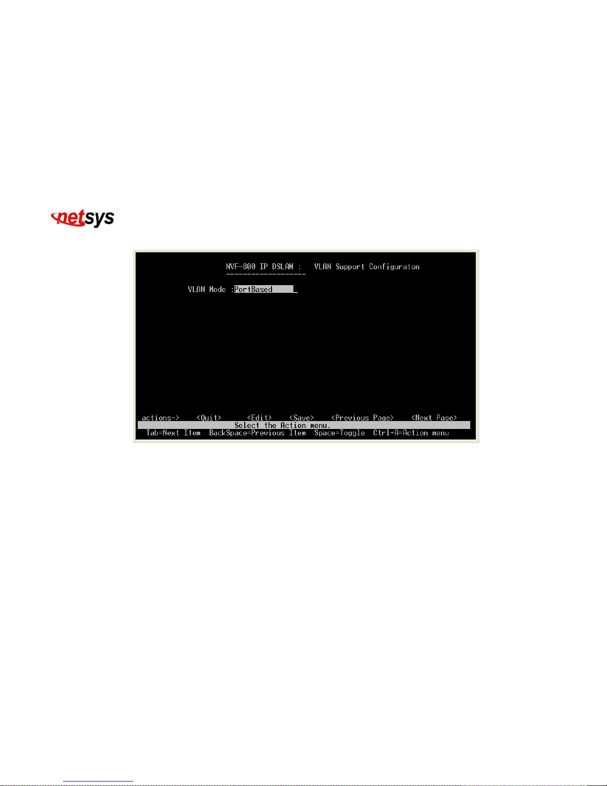
VLAN Mode: PortBased(Figure 4.23)
Figure 4.23 VLAN Mode: Port Based
Page 50
NVF-800S 4-Band VDSL IP DSLAM USER’S MANUAL Ver_B.2
49
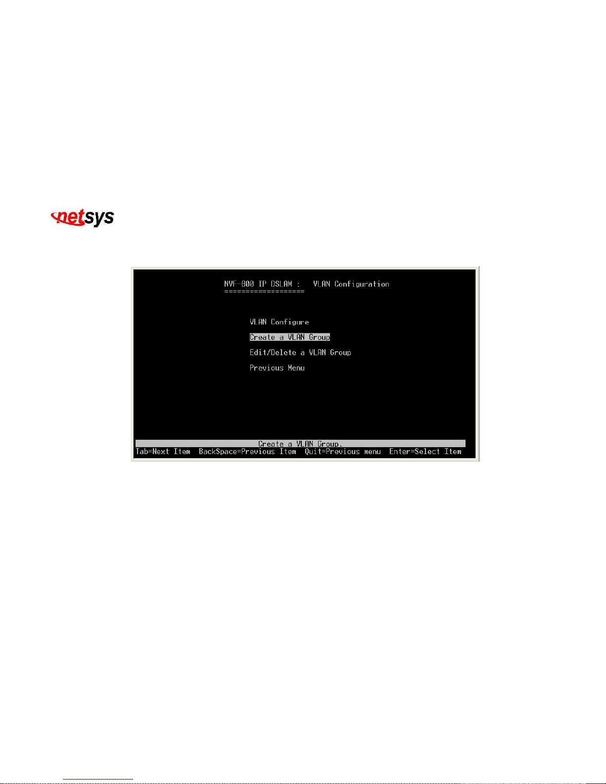
4.1.1.2.4.2 Create a VLAN Group
You can create a new VLAN Group. (Figure 4.24)
Figure 4.24 Create a VLAN Group
Page 51
NVF-800S 4-Band VDSL IP DSLAM USER’S MANUAL Ver_B.2
50
4.1.1.2.4.3 Edit/Delete a VLAN Group
Edit/Delete a VLAN Group. (Figure 4.25)
Figure 4.25 Edit or Delete a VLAN Group
Page 52
NVF-800S 4-Band VDSL IP DSLAM USER’S MANUAL Ver_B.2
51
4.1.1.2.5 Priority Configuration
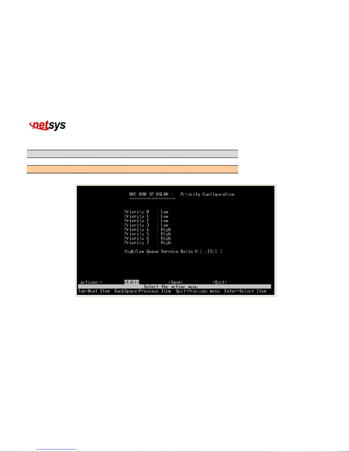
Display or change port priority configuration. (Figure 4.26)
Item Description
Priority 0 to 7:
Shows the priority if it is either low or high.
High/Low Queue Service Ratio H/L:
Shows the ratio of the priority high/low.
Figure 4.26 802.1p QoS(Quality of Service) Priority Configuration
Page 53
NVF-800S 4-Band VDSL IP DSLAM USER’S MANUAL Ver_B.2
52
4.1.1.2.6 MAC Address Configuration
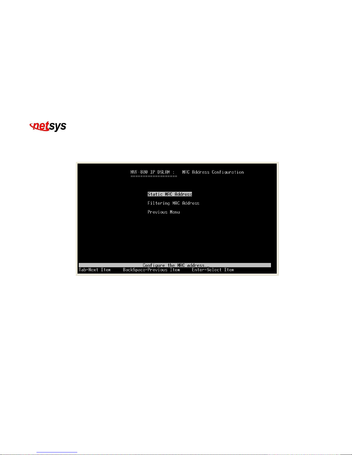
Select the “Mac Address Configuration”. The menu below includes the sub-menus of Static Mac Address and Filtering Mac
Address (Figure 4.27)
Figure 4.27 Static Mac Address Configuration
Page 54
NVF-800S 4-Band VDSL IP DSLAM USER’S MANUAL Ver_B.2
53
4.1.1.2.6.1 Static MAC Address
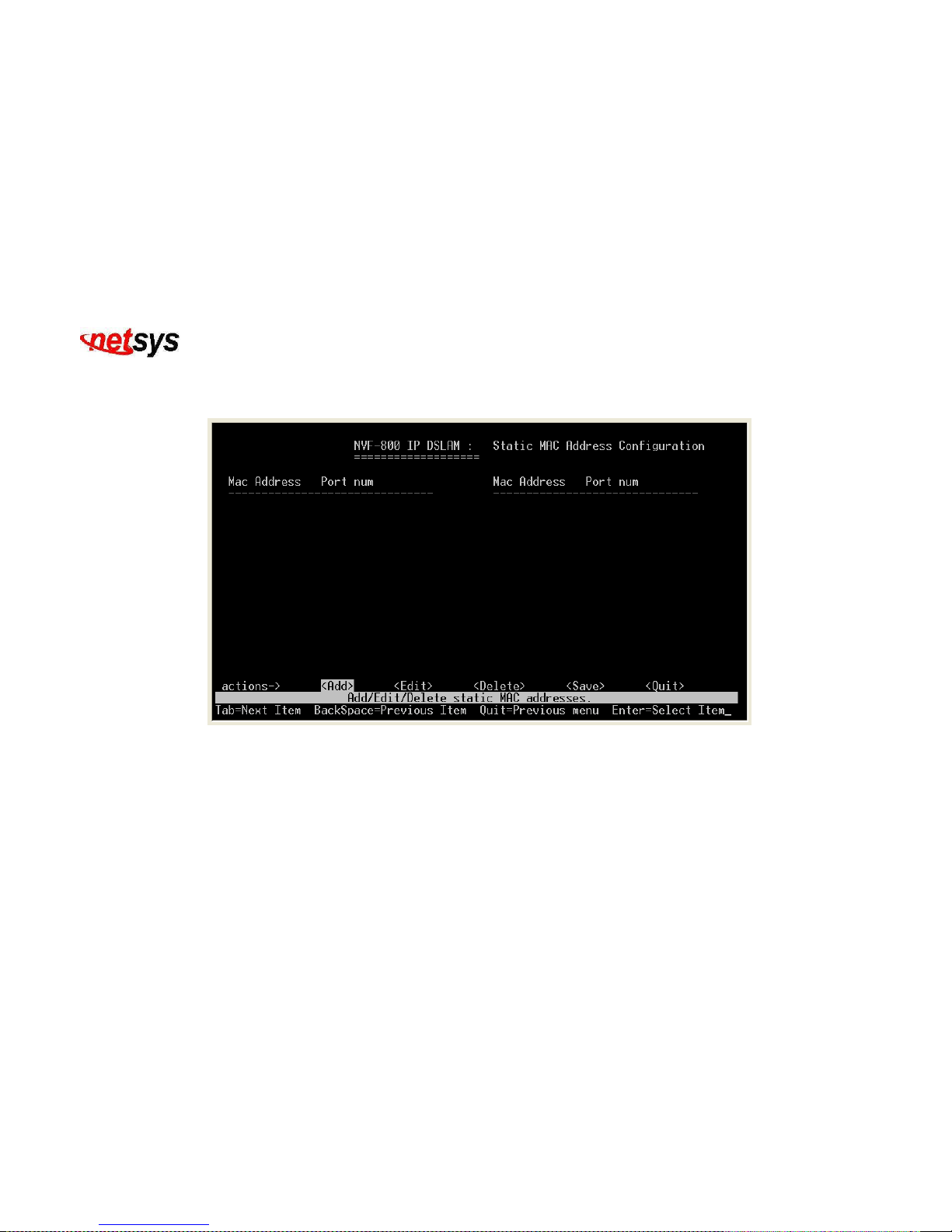
Configure the Static MAC address. (Figure 4.28)
Figure 4.28 Static Mac Address Configuration
Page 55
NVF-800S 4-Band VDSL IP DSLAM USER’S MANUAL Ver_B.2
54
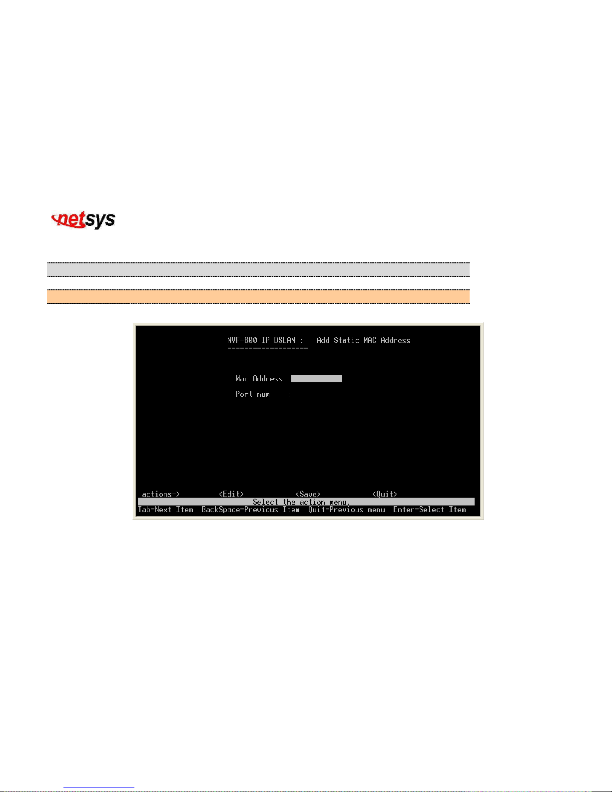
4.1.1.2.6.1.1 Add Static MAC Address
Add Static MAC Address(Figure 4.29)
Item Description
Mac Address:
Input static MAC address for the selected port number.
Port num:
Input port number for the set static MAC address. Valid Range is from 1 to 10.
Figure 4.29 Add Static Mac Address
Page 56
NVF-800S 4-Band VDSL IP DSLAM USER’S MANUAL Ver_B.2
55
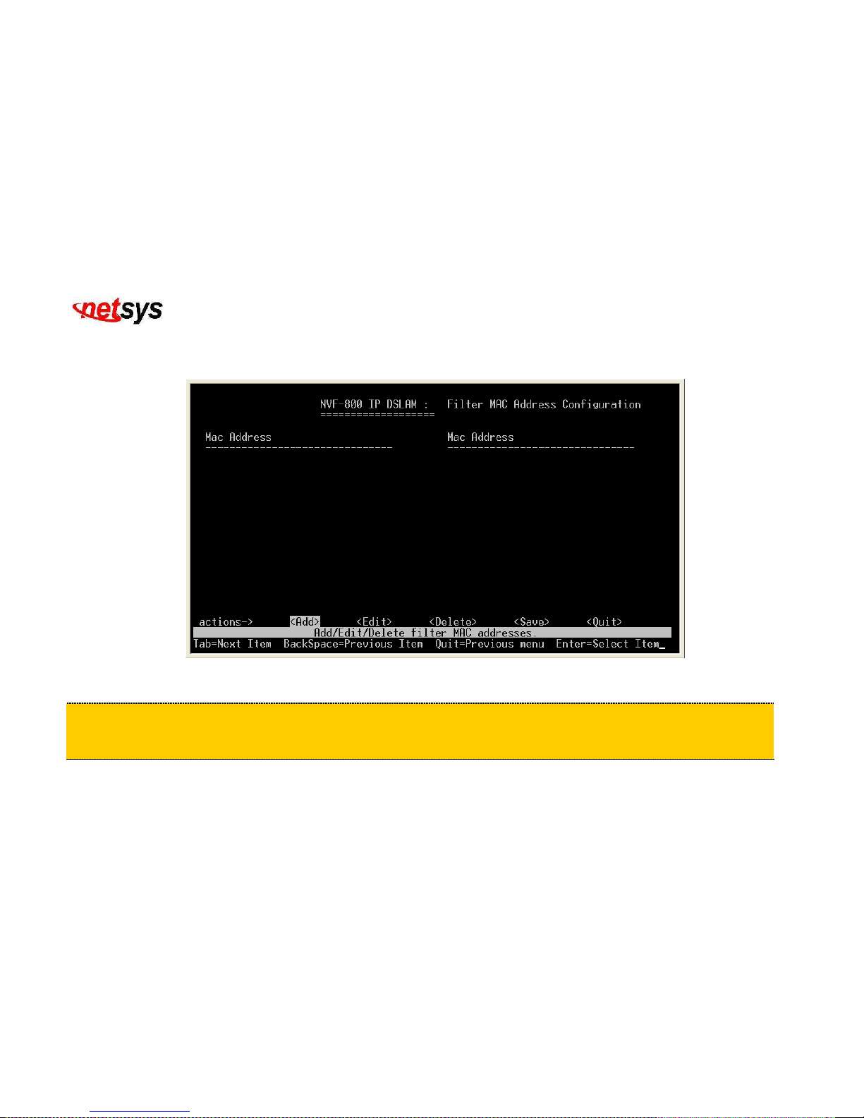
4.1.1.2.6.2 Filtering MAC Address
Filtering the MAC address configuration. (Figure 4.30)
Figure 4.30 Filter Mac Address
Tip:
MAC address filtering allows the switch to drop unwanted traffic. Traffic is filtered based on the destination addresses.
For example, if your network is congested because of high utilization from one MAC address, you can filter all traffic
transmitted from that MAC address, restoring network flow while you troubleshoot the problem.
Page 57
NVF-800S 4-Band VDSL IP DSLAM USER’S MANUAL Ver_B.2
56
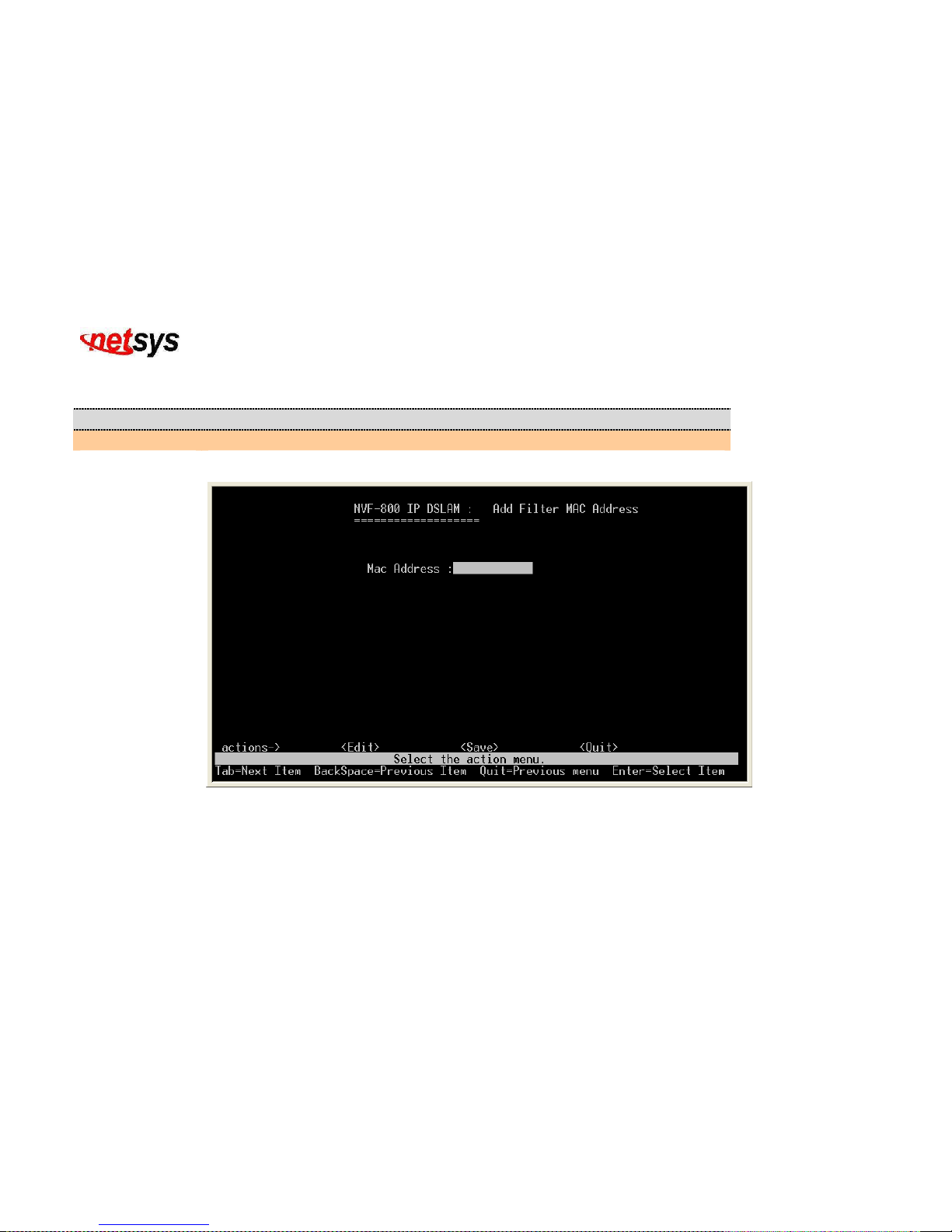
4.1.1.2.6.2.1 Add Filtering MAC Address
Item Description
Mac Address:
Input the MAC address of certain device to be filtered out.
(Figure 4.31)
Figure 4.31 Add Filter Mac Address
Page 58
NVF-800S 4-Band VDSL IP DSLAM USER’S MANUAL Ver_B.2
57
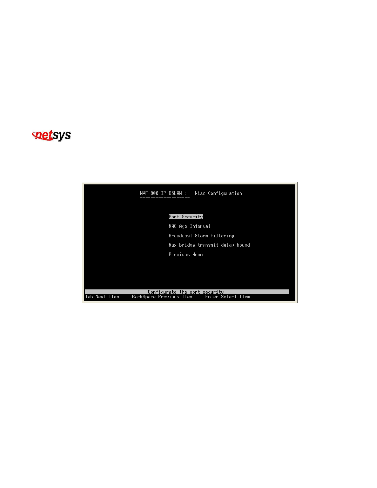
4.1.1.2.7 Misc Configuration
Select the “Misc Configuration”. The menu below includes the sub-menus of Port Security, Mac Age interval, Broadcast
Storm Filtering and Max bridge transmit delay bound. Please configure the miscellaneous items as follows. (Figure
4.32)
Figure 4.32 Select “Misc Confiruration”
Page 59
NVF-800S 4-Band VDSL IP DSLAM USER’S MANUAL Ver_B.2
58
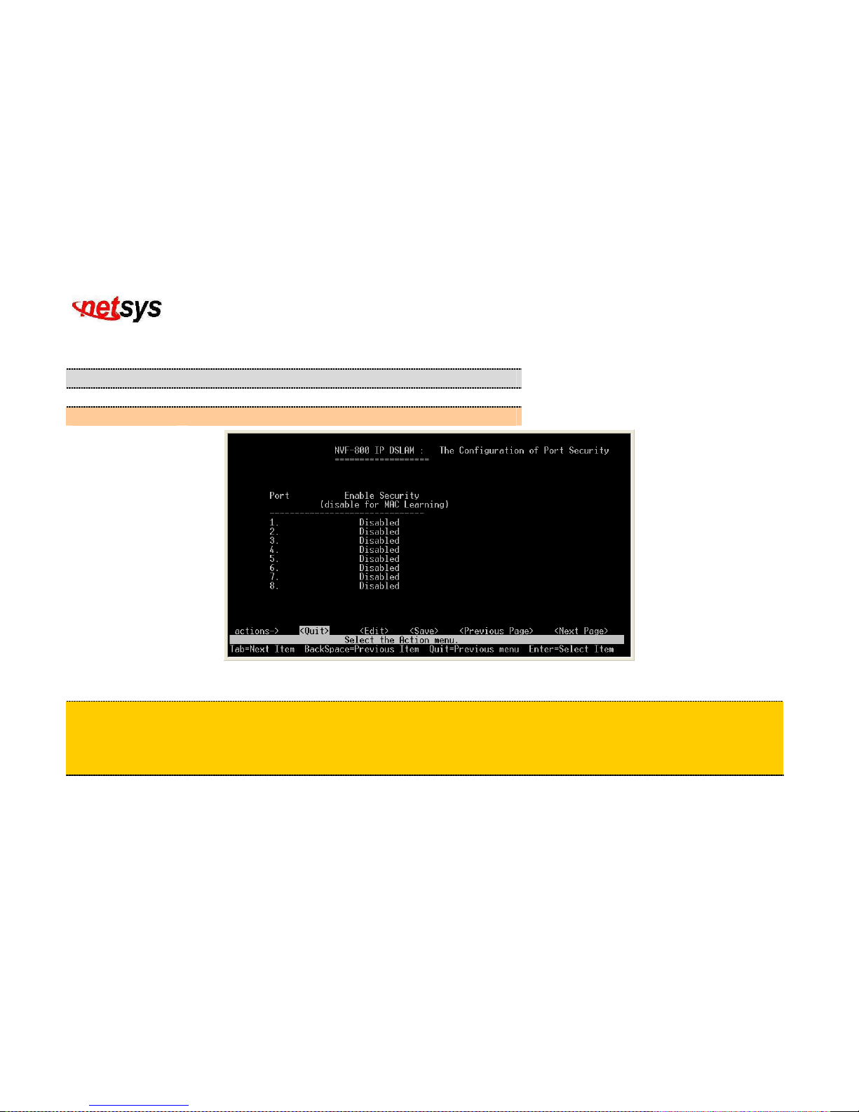
4.1.1.2.7.1 Port Security
Configure the port security. (Figure 4.33)
Item Description
Port:
Shows the port number of NVF-800S VDSL IP DSLAM.
Enable Security:
Enable or disable for Port security.
Figure 4.33 Port Security
Tip:
A port in security mode will be “locked” without permission of address learning. Only the incoming packets with SMAC already
existing in the address table can be forwarded normally. User can disable the port from learning any new MAC addresses, then use
the static MAC addresses screen to define a list of MAC addresses that can use the secure port.enter the settings, then choice
save the changes on this page.
Page 60
NVF-800S 4-Band VDSL IP DSLAM USER’S MANUAL Ver_B.2
59
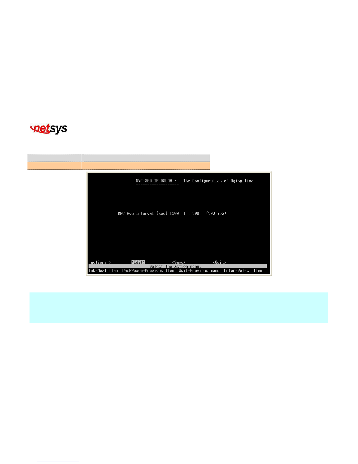
4.1.1.2.7.2 MAC Age Interval
Configure the MAC aging time. (Figure 4.34)
Item Description
MAC Age Interval:
MAC aging interval is from 300 to765 seconds.
Figure 4.34 Mac Aging Time Configuration
Note:
If not set the aging-time, ip address and mac address mapping will be always there, even for a computer using the same ip
to access does not automatically update the mac table. After setting the aging-time, every time of Aging time interval will
arrive to relearn the MAC address table.
In fact, this time does not need special setting, default MAC age interval is 300 seconds.
Page 61
NVF-800S 4-Band VDSL IP DSLAM USER’S MANUAL Ver_B.2
60
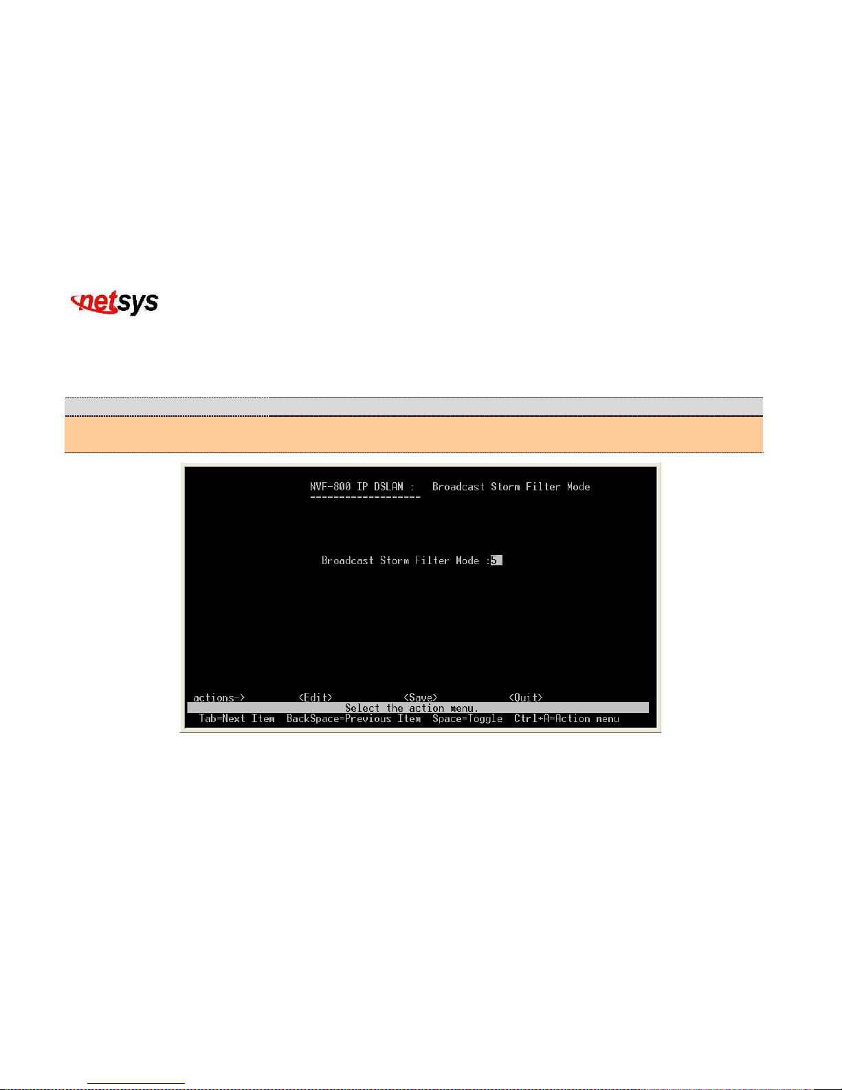
4.1.1.2.7.3 Broadcast Storm Filtering
To configure broadcast storm control, enable it and set the upper threshold for individual ports. The threshold is the percentage of the
port's total bandwidth used by broadcast traffic. When broadcast traffic for a port rises above the threshold you set, broadcast storm
control becomes active. (Figure 4.35)
Item Description
Broadcast Storm Filter Mode:
Broadcast storm filter mode can either be 5%, 10%, 15%, 20%, 25% or NO. Default
broadcast storm filter is at 5%.
Figure 4.35 Broadcast Storm Filter mode
Page 62
NVF-800S 4-Band VDSL IP DSLAM USER’S MANUAL Ver_B.2
61
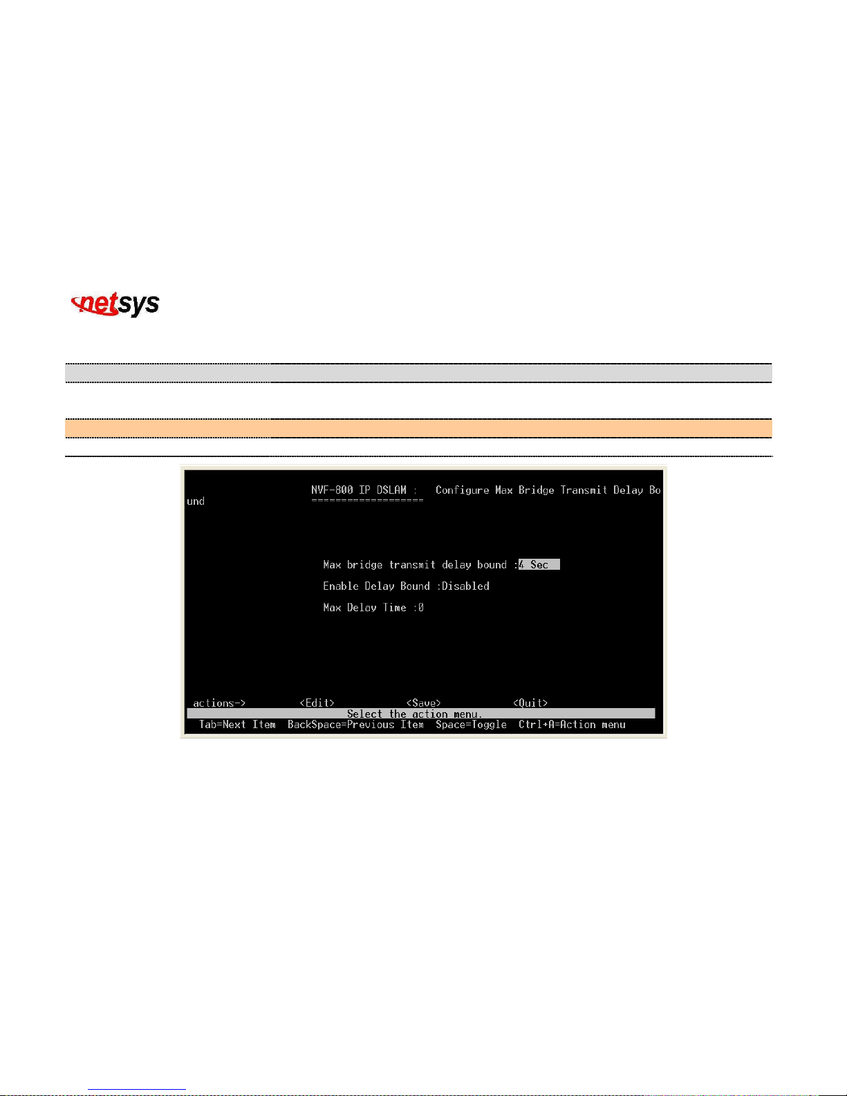
4.1.1.2.7.4 Max Bridge Transmit Delay Bound
Configure the maximum bridge transmit delay bound. Default maximum bridge transmit delay bound is 4 seconds. (Figure 4.36)
Item Description
Max bridge transmit delay bound:
Limit the packets queuing time in switch. If enable, the packets queued exceed will be drop.
This valid value are 1sec, 2 sec,3sec, 4 sec and off.
Enable Delay Bound:
Delay bound can either be Enable or Disable.
Maximum Delay Time:
Maximum delay time is from 1ms to 255ms. Disabled is 0.
Figure 4.36 Configure the maximum bridge transmit delay bound.
Page 63
NVF-800S 4-Band VDSL IP DSLAM USER’S MANUAL Ver_B.2
62
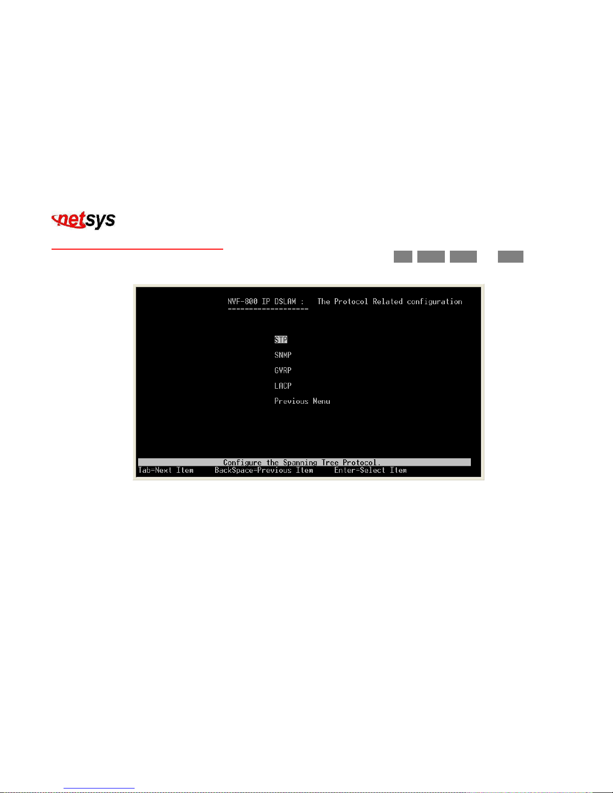
4.1.1.3 Protocol Related Configuration
Select the “Protocol Related Configuration”. The menu below includes the sub-menus of STP, SNMP, GVRP and LACP. (Figure
4.37)
Figure 4.37 Configure the Protocol Related
Page 64
NVF-800S 4-Band VDSL IP DSLAM USER’S MANUAL Ver_B.2
63
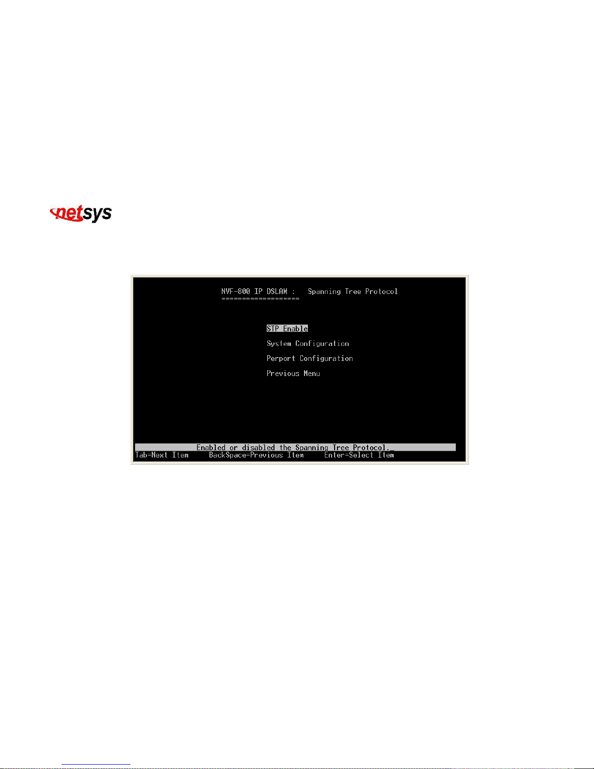
4.1.1.3.1 STP
Select the “STP”. The menu below includes the sub-menus of STP Enable, System Configuration and Perport Configuration.
(Figure 4.38)
Figure 4.38 Spanning Tree configuration
Page 65
NVF-800S 4-Band VDSL IP DSLAM USER’S MANUAL Ver_B.2
64
4.1.1.3.1.1 STP Enable
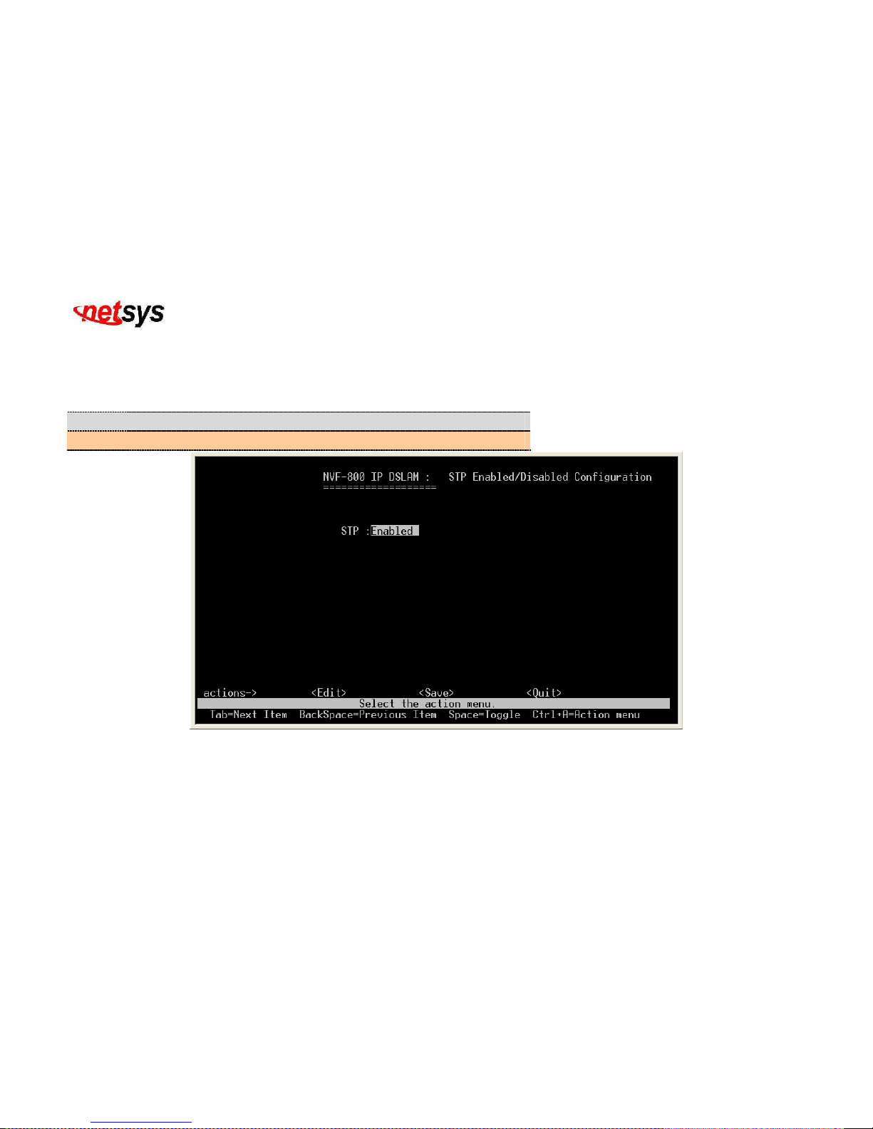
The Spanning-Tree Protocol (STP) is a standardized method (IEEE 802.1d ) for used to prevent forwarding loops on a LAN. When
STP enabled, to ensure that only one path at a time is active between any two nodes on the network. (Figure 4.39)
We are recommended that you enable STP on all switches ensures a single active path on the network.
Item Description
STP:
Spanning Tree Protocol can either be enabled or disabled.
Figure 4.39 STP Enable / Disable
Page 66
NVF-800S 4-Band VDSL IP DSLAM USER’S MANUAL Ver_B.2
65
4.1.1.3.1.2 System Configuration
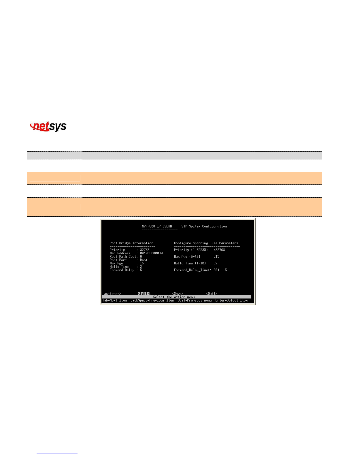
Configure the STP system information. (Figure 4.40)
Item Description
Priority:
A priority value used to identify the root bridge. The bridge with the lowest value has the highest priority
and is selected as the root. Valid input priority range is from 1 to 65535. Default priority is 32768.
Max Age:
The number of seconds a bridge waits without receiving . Spanning-Tree Protocol configuration messages
before attempting a reconfiguration.Valid input max age range is from 6 to 40. Default max age is 20.
Hello Time:
The number of seconds between the transmission of Spanning-Tree Protocol configuration
messages.Valid input hello time range is from 1 to 10. Default hello time is 2
Forward Delay Time:
The number of seconds a port waits before changing from its Spanning-Tree Protocol learning and
listening states to the forwarding state.Valid input forward delay time range is from 4 to 30. Default forward
delay time is 5.
Figure 4.40 STP System Configuration
Page 67
NVF-800S 4-Band VDSL IP DSLAM USER’S MANUAL Ver_B.2
66
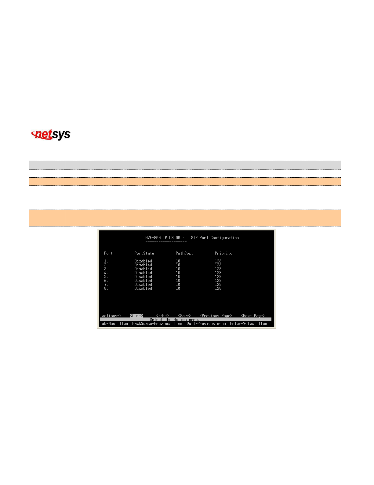
4.1.1.3.1.3 Perport Configuration
Configure the STP per port configuration. Default pathcost is 10 and priority is 128. (Figure 4.41)
Item Description
Port:
Shows the port number of NVF-800S VDSL IP DSLAM.
PortState:
Shows the condition of the port if it is enabled or disabled.
PathCost:
Specifies the path cost of the port that switch uses to determine which port are the forwarding ports the lowest
number is forwarding ports, the rage is 1-65535 and default value base on IEEE802.1D 10Mb/s = 50-600 100Mb/s =
10-60 1000Mb/s = 3-10
Priority:
You can make it more or less likely to become the root port, the range is from 0 to 255,default setting is 128, the
lowest number has the highest priority.
Figure 4.41 STP Port Configuration
Page 68
NVF-800S 4-Band VDSL IP DSLAM USER’S MANUAL Ver_B.2
67
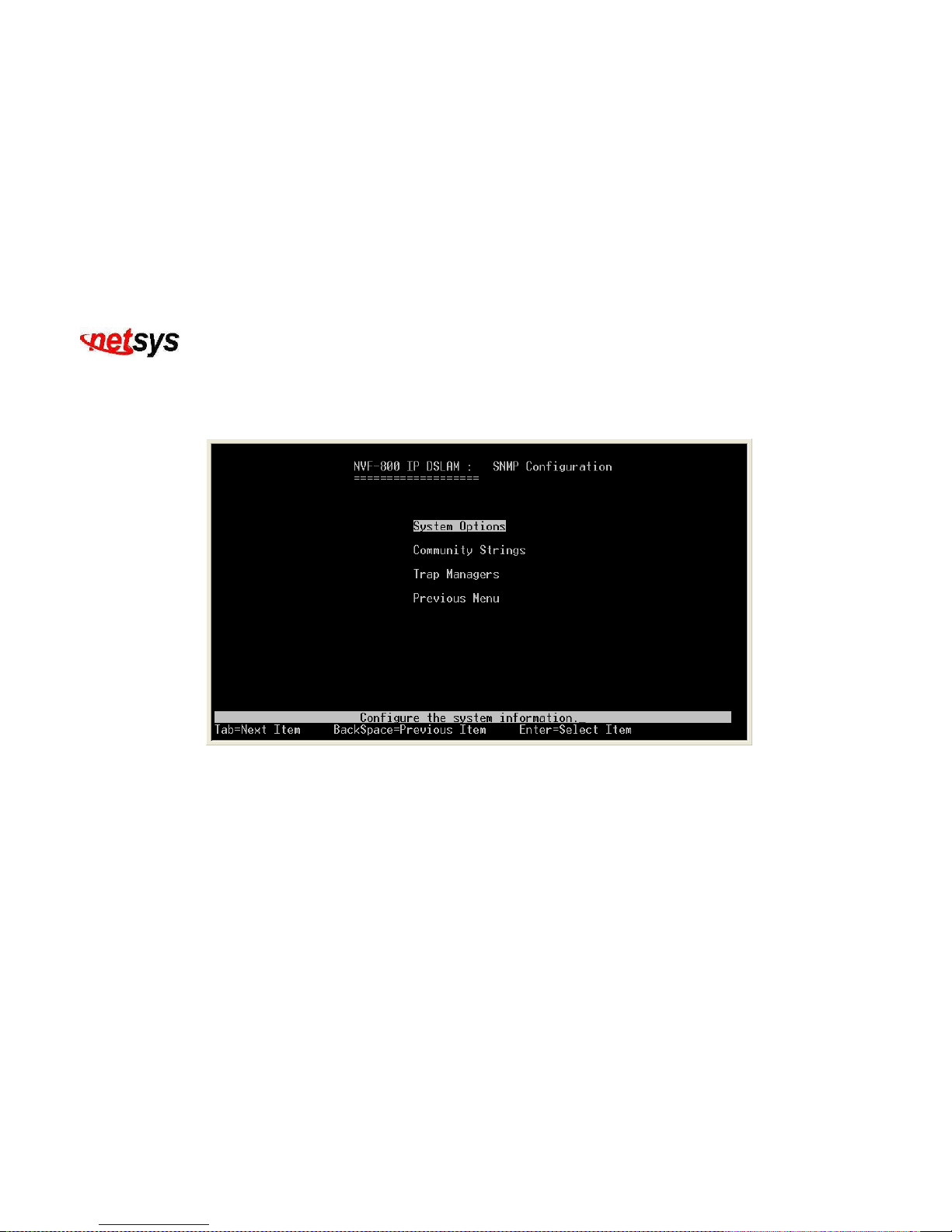
4.1.1.3.2 SNMP
Select the “SNMP”. The menu below includes the sub-menus of System Options, Community Strings and Trap Mangers.
SNMP means Simple Network Manager Protocol. (Figure 4.42)
Figure 4.42 SNMP Configuration
Page 69
NVF-800S 4-Band VDSL IP DSLAM USER’S MANUAL Ver_B.2
68
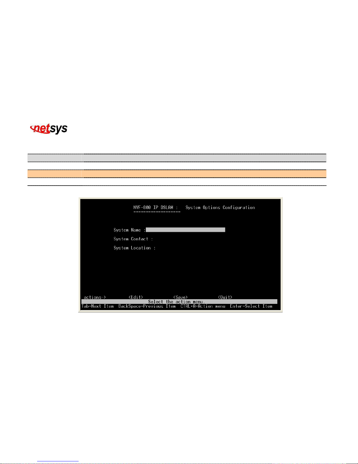
4.1.1.3.2.1 System Options
Configure the system information. (Figure 4.43)
Item Description
System Name:
Configuration to your own system name up to 32 characters.
System Contact:
Configuration to your own system contact up to 32 characters. (i.e. a person or organization)
System Location:
Configuration to your own system location up to 32 characters.
Figure 4.43 System Options Configuration
Page 70
NVF-800S 4-Band VDSL IP DSLAM USER’S MANUAL Ver_B.2
69
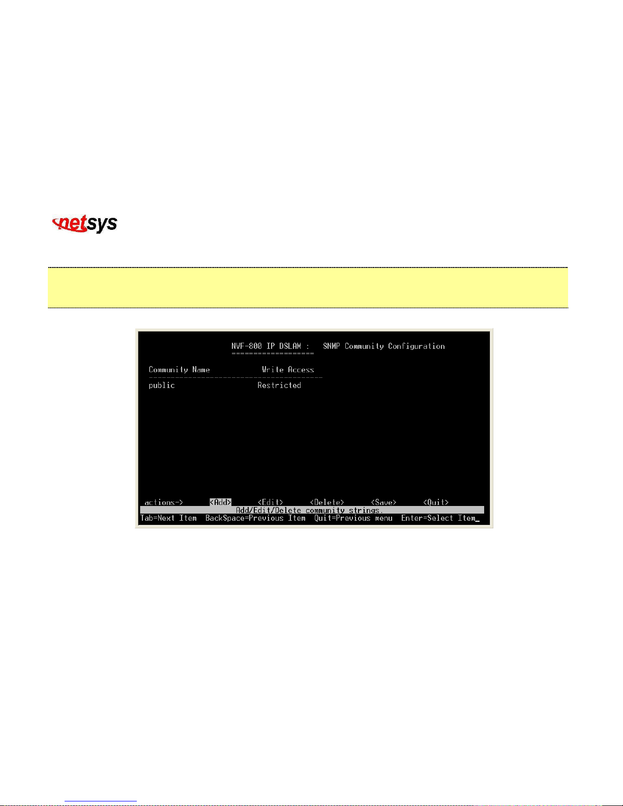
4.1.1.3.2.2 Community Strings
Configure the community. (Figure 4.44)
For example,community name set to “public”, Write access set to “Restricted”, means enable requests accompanied by this
string to display MIB-object information. And another community name set to “private”, Write access set to “Unrestricted”,
means enable requests accompanied by this string to display MIB-object information and to set MIB objects.
Figure 4.44 SNMP Community Configuration
Page 71
NVF-800S 4-Band VDSL IP DSLAM USER’S MANUAL Ver_B.2
70
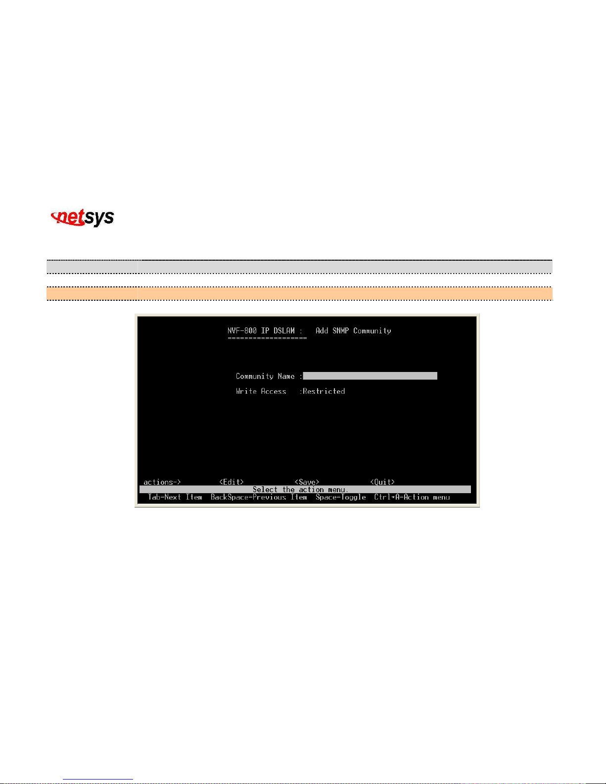
4.1.1.3.2.2.1 Add SNMP Community
Add SNMP community. (Figure 4.45)
Item Description
Community Name:
Input valid community name up to 32 characters to be included in the SNMP community.
Write Access:
Write access can either be restricted or unrestricted.
Figure 4.45 Add SNMP Community
Page 72
NVF-800S 4-Band VDSL IP DSLAM USER’S MANUAL Ver_B.2
71
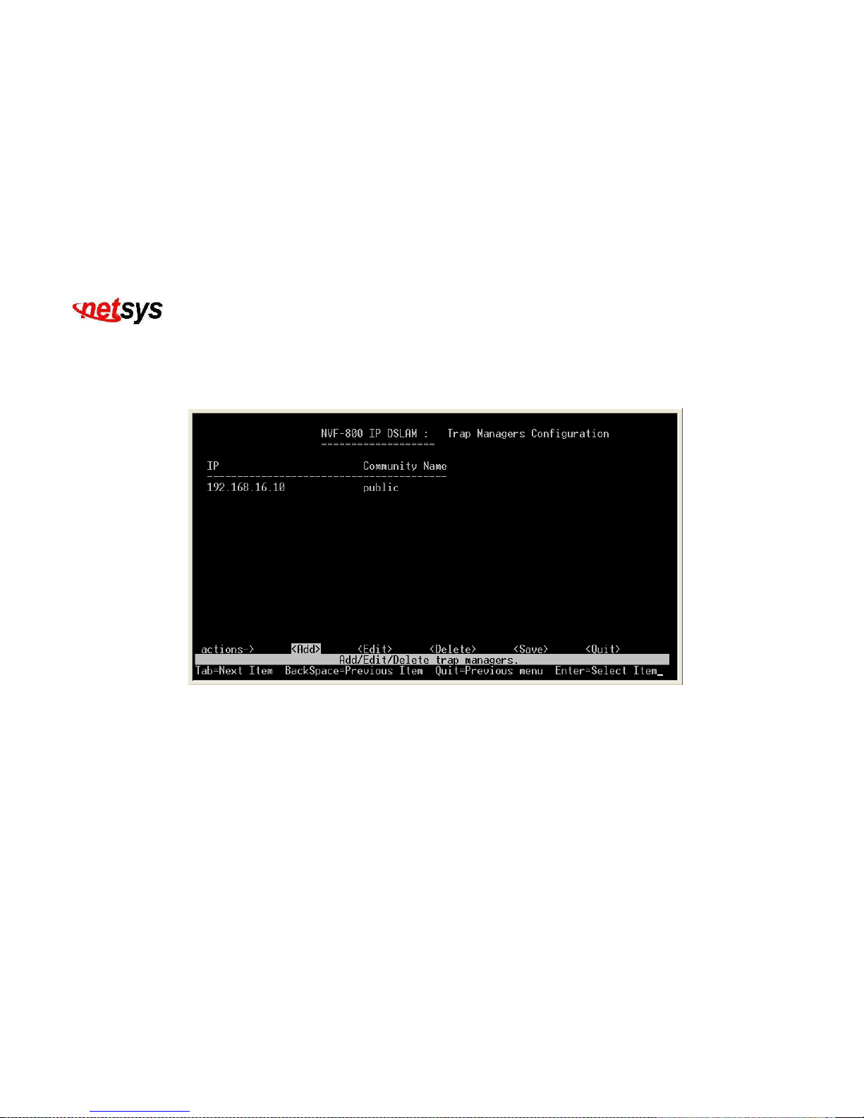
4.1.1.3.2.3 Trap Managers
A trap manager is a management station that receives traps, the system alerts generated by the IP DSLAM. If no trap
manager is defined, no traps are issued. Create a trap manager by entering the IP address of the station and a community
string. (Figure 4.46)
Figure 4.46 Trap Managers Confiruration
Page 73
NVF-800S 4-Band VDSL IP DSLAM USER’S MANUAL Ver_B.2
72
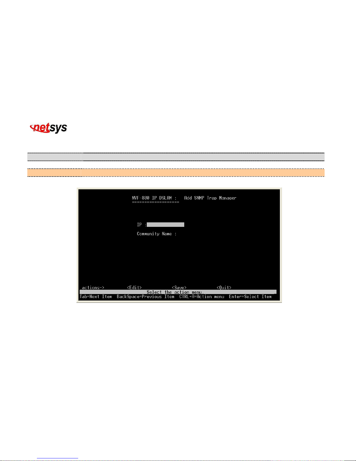
4.1.1.3.2.3.1 Add SNMP Trap Manager
Add SNMP trap manager. (Figure 4.47)
Item Description
IP:
Input IP address to be included in the SNMP trap manager.
Community Name:
Input valid community name up to 32 characters to be included in the SNMP trap manager.
Figure 4.47 Add SNMP Trap Manager
Page 74
NVF-800S 4-Band VDSL IP DSLAM USER’S MANUAL Ver_B.2
73
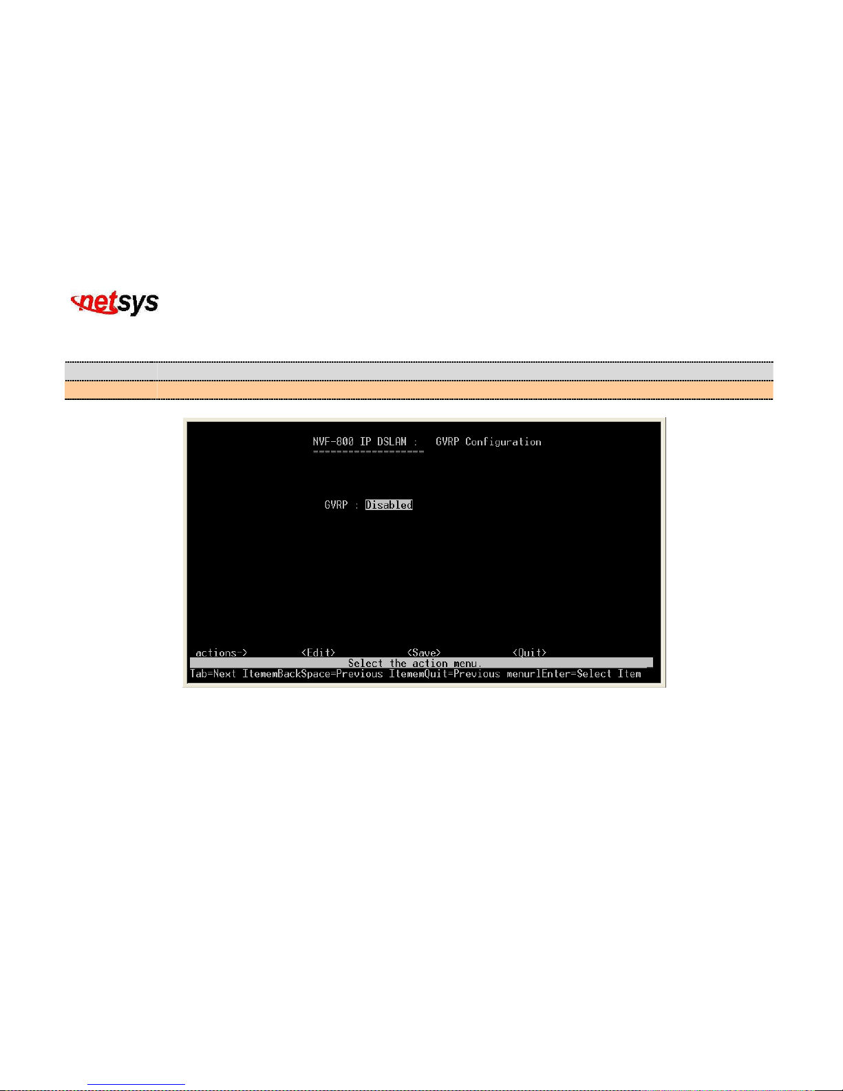
4.1.1.3.3 GVRP
Default GVRP is disabled. (Figure 4.48) Please refer to section 4.1.1.2.4.1 VLAN Configure.
Item Description
GVRP:
GARP VLAN Registration Protocol can either be enabled or disabled.
Figure 4.48 GVRP Configuration Enable / Disable
Page 75
NVF-800S 4-Band VDSL IP DSLAM USER’S MANUAL Ver_B.2
74
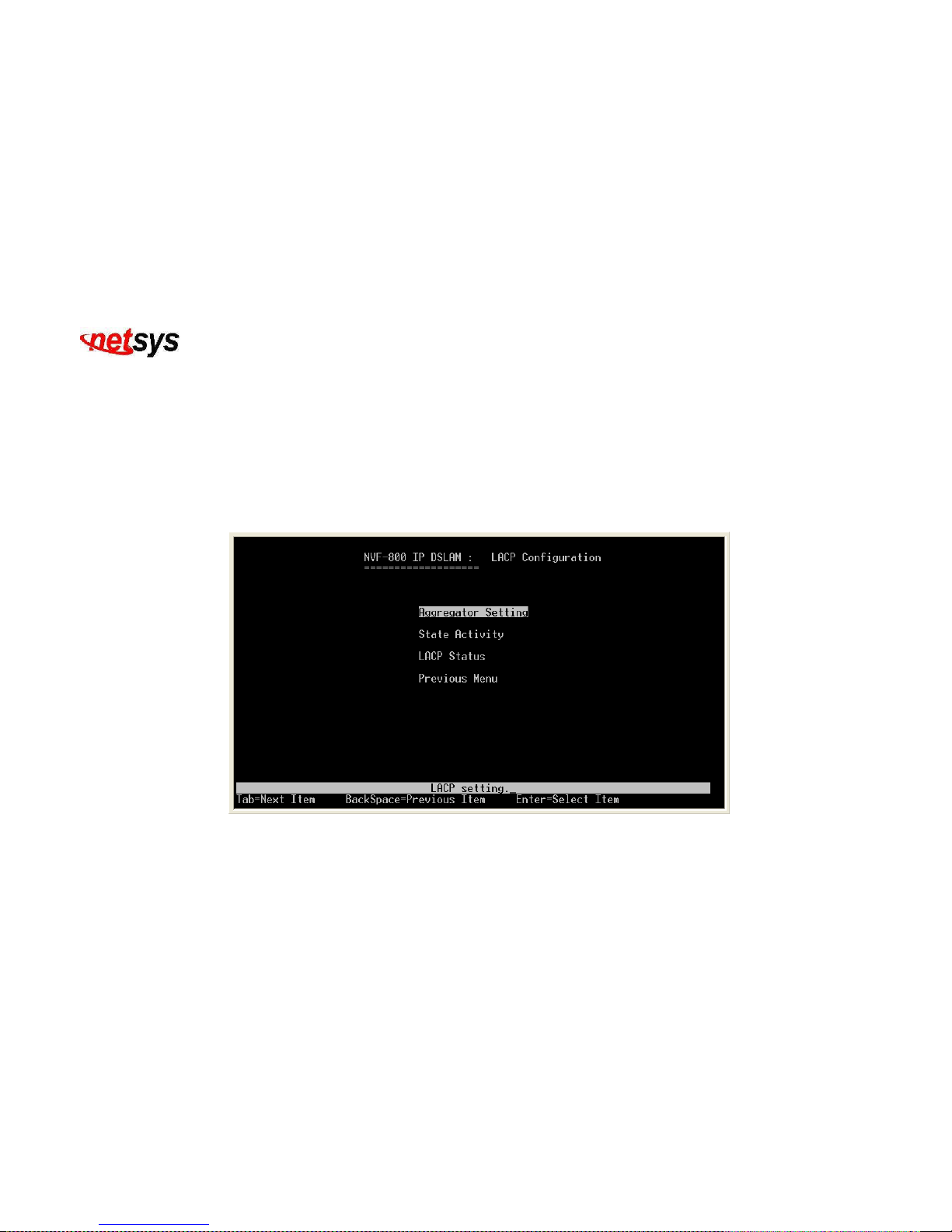
4.1.1.3.4 LACP
Select the “LACP ”. The menu below includes the sub-menus of Aggregator Setting, State Activity and LACP Status.
The Link Aggregation Control Protocol (LACP) provides a standardized means for exchanging information between
Partner Systems on a link to allow their Link Aggregation Control instances to reach agreement on the identity of the Link
Aggregation Group to which the link belongs, move the link to that Link Aggregation Group, and enable its transmission
and reception functions in an orderly manner. In conclusion, Link aggregation lets you group up to eight consecutive ports
into a single dedicated connection. This feature can expand bandwidth to a device on the network. LACP operation
requires full-duplex mode, more detail information refers to IEEE802.3ad. (Figure 4.49)
Figure 4.49 LACP Configuration
Page 76
NVF-800S 4-Band VDSL IP DSLAM USER’S MANUAL Ver_B.2
75
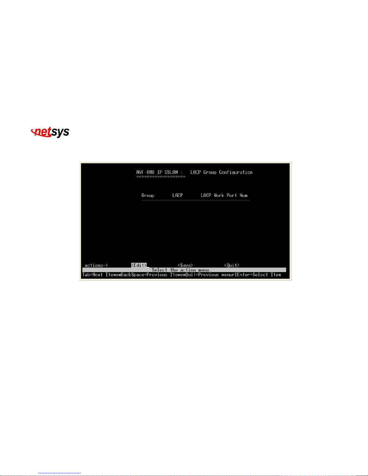
4.1.1.3.4.1 Aggregator Setting
LACP setting. (Figure 4.50)
Figure 4.50 LACP Group Configuration
Page 77
NVF-800S 4-Band VDSL IP DSLAM USER’S MANUAL Ver_B.2
76
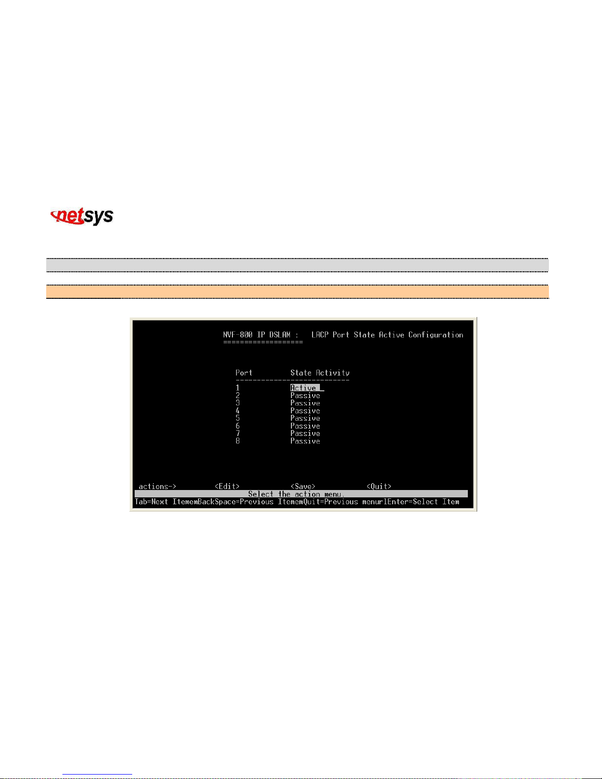
4.1.1.3.4.2 State Activity
Configure the state activity. (Figure 4.51)
Item Description
Port:
Shows the port number of NVF-800S VDSL IP DSLAM.
State Activity:
State Activity for LACP can either be active or passive.
Figure 4.51 LACP Port State Active Configuration
Page 78
NVF-800S 4-Band VDSL IP DSLAM USER’S MANUAL Ver_B.2
77
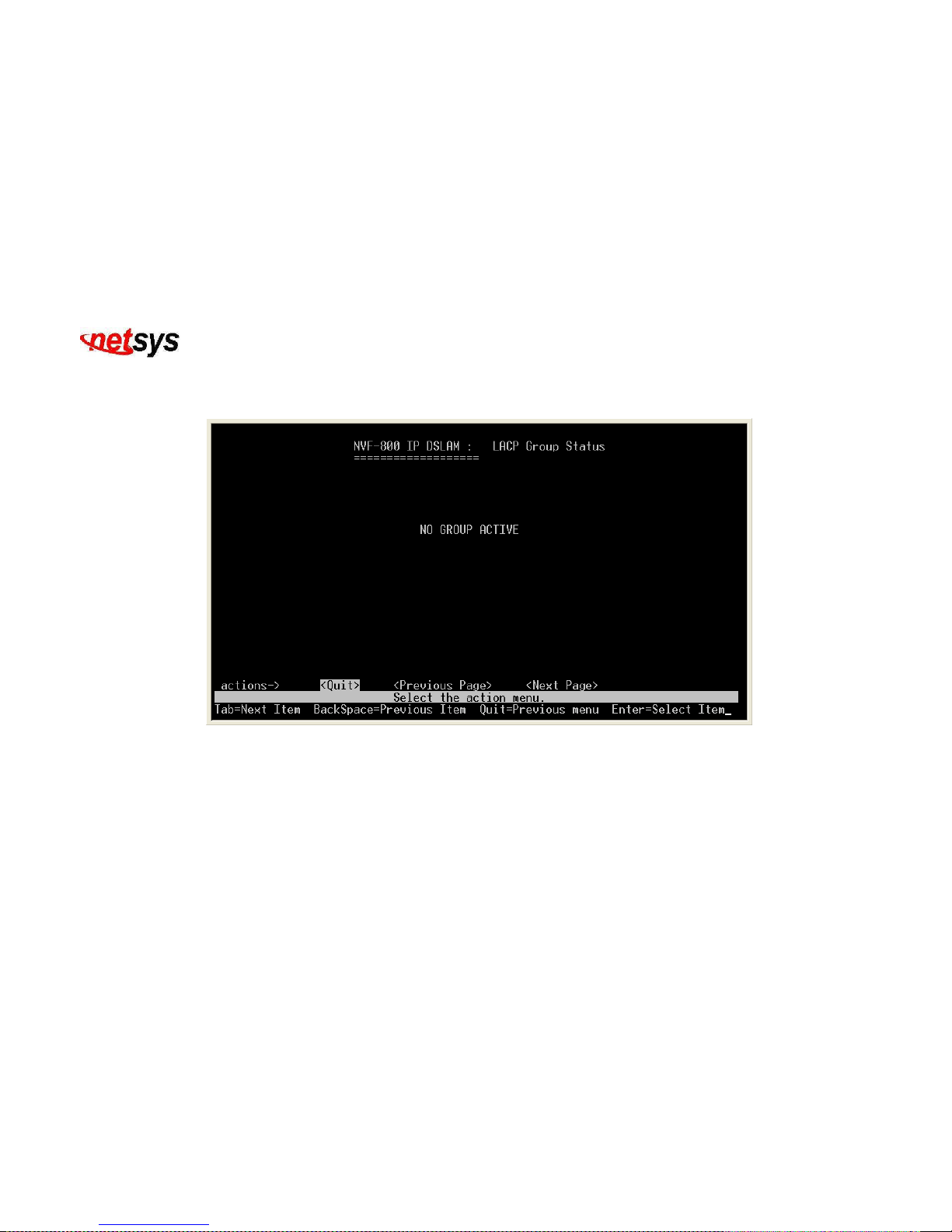
4.1.1.3.4.3 LACP Status
Show the LACP status. This page is no group active. LACP don’t working. (Figure 4.52)
Figure 4.52 LACP Group Status
Page 79
NVF-800S 4-Band VDSL IP DSLAM USER’S MANUAL Ver_B.2
78
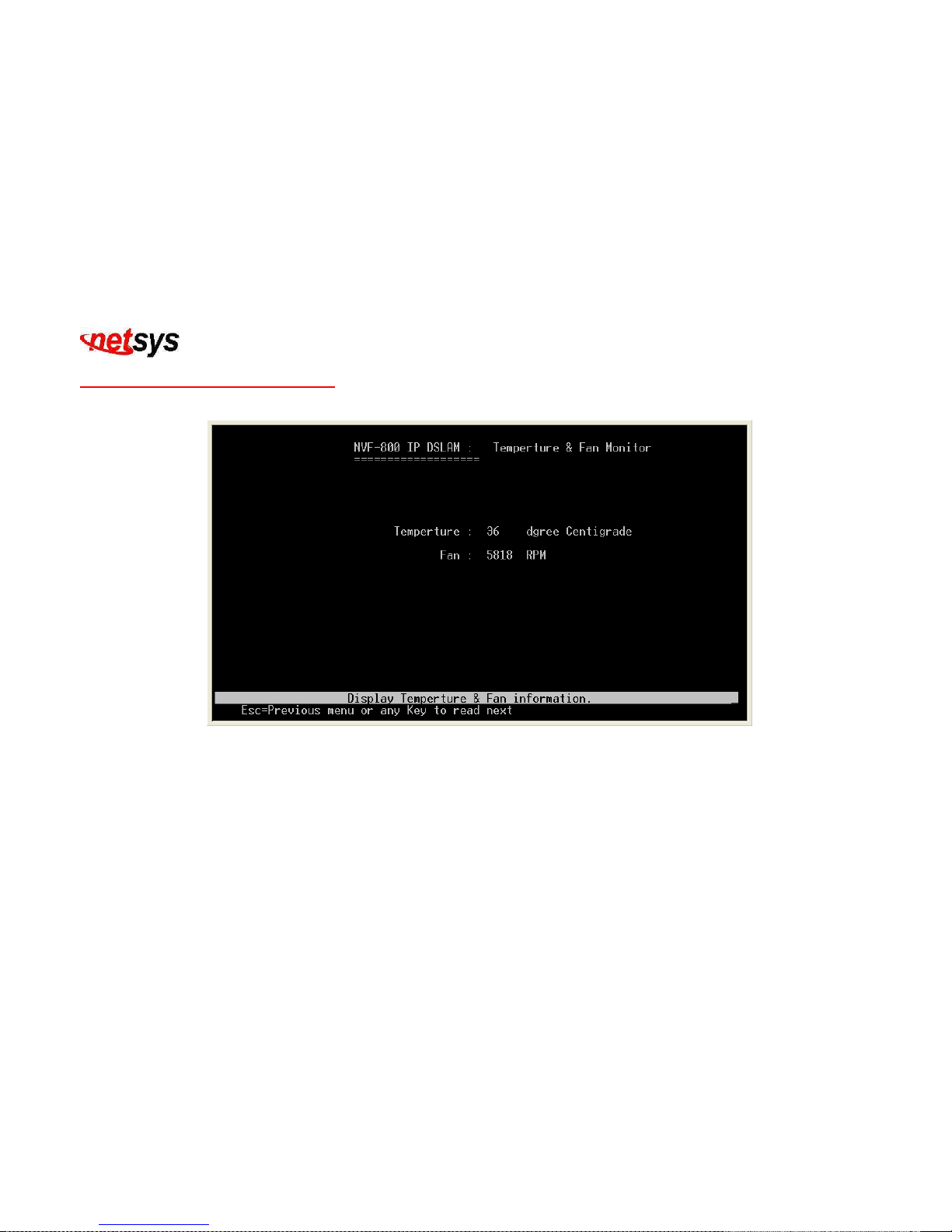
4.1.1.4 Temperature and Fan Monitor
Display the temperature in degrees Celsius(°C ) and fan monitor in RPM. (Figure 4.53)
Figure 4.53 Temperature & FAN Monitor
Page 80
NVF-800S 4-Band VDSL IP DSLAM USER’S MANUAL Ver_B.2
79
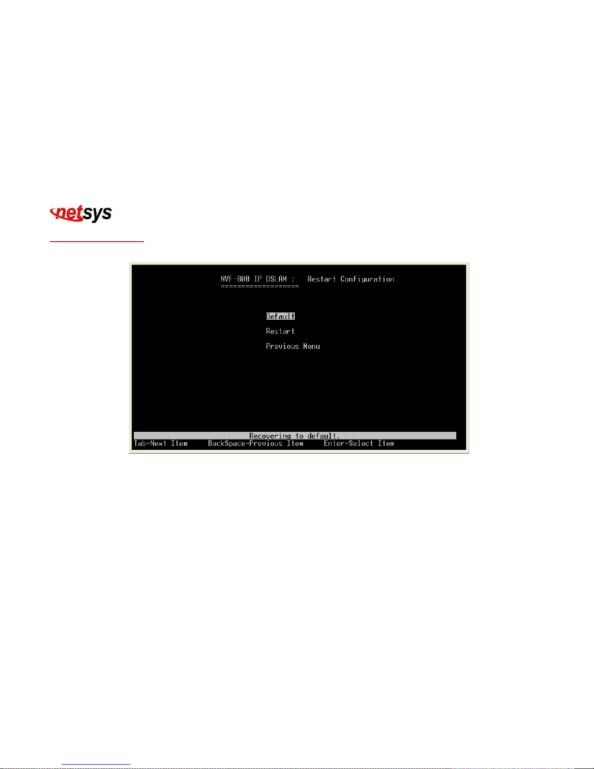
4.1.1.5 Reboot Switch
Select the “Restart ”. The menu below includes the sub-menus of Default and Restart.(Figure 4.54)
Figure 4.54 Restart Configuration
Page 81
NVF-800S 4-Band VDSL IP DSLAM USER’S MANUAL Ver_B.2
80
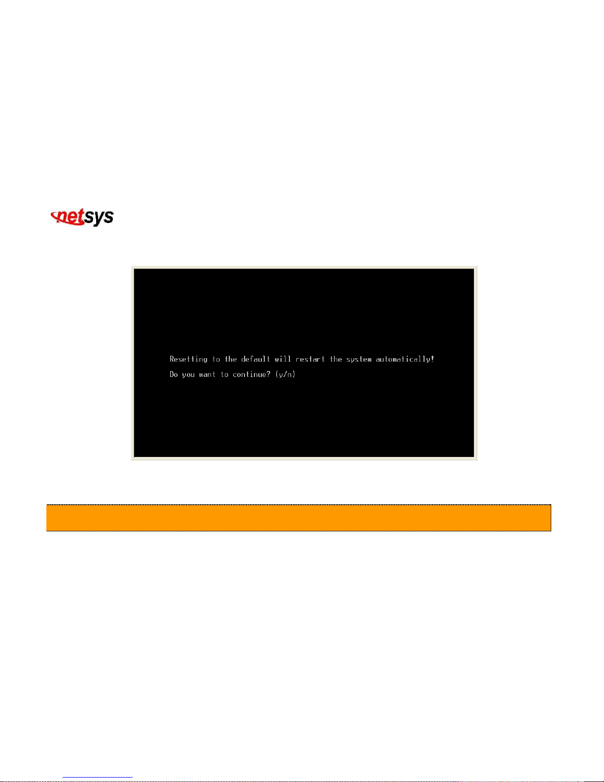
4.1.1.5.1 Default
Recovering to default. (Figure 4.55)
Figure 4.55 Resetting to the default system
Caution:
1. All settings will return to factory defaults.
2. After set to default system, please reboot the system.
Page 82

NVF-800S 4-Band VDSL IP DSLAM USER’S MANUAL Ver_B.2
81
Choose “Yes”
Reset the system to default automatically. (
Figure 4.56)
If No, It will go back to the previous menu.
Figure 4.56 Resetting to the default
Page 83
NVF-800S 4-Band VDSL IP DSLAM USER’S MANUAL Ver_B.2
82
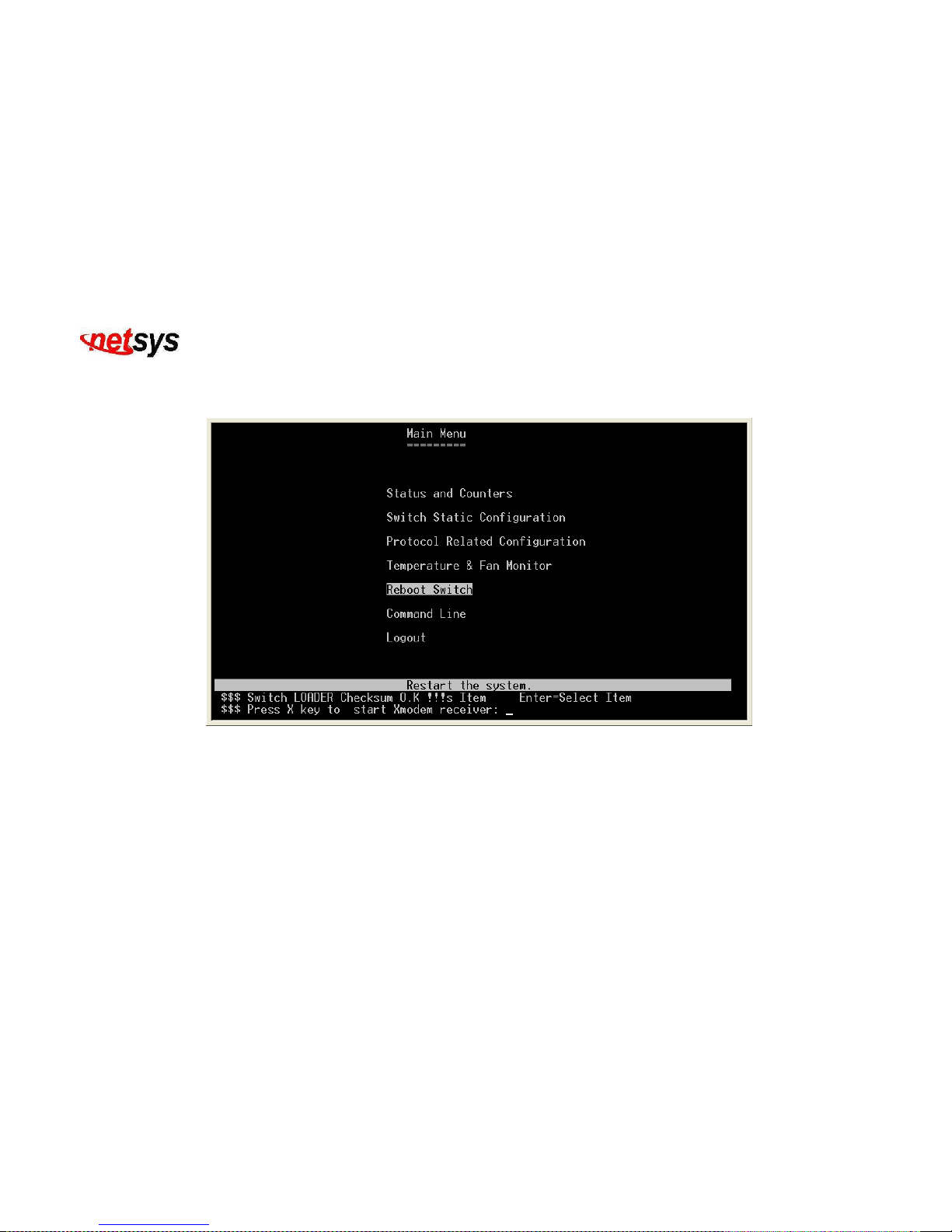
4.1.1.5.2 Reboot Switch
Restart the system. (Figure 4.57)
Figure 4.57 Reboot Switch
Page 84
NVF-800S 4-Band VDSL IP DSLAM USER’S MANUAL Ver_B.2
83
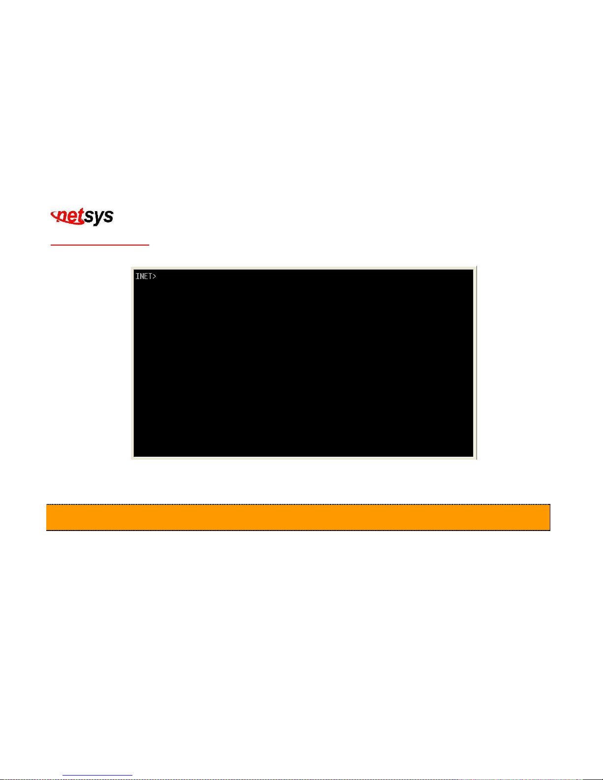
4.1.1.6 Command Line
Command Line. (Figure 4.58)
Figure 4.58 Command Line
Caution:
1. This function is only used to debug for the engineer.
2. If you want to exit the command line, please input “quit”, then press “enter” key to exit the command line.
Page 85
NVF-800S 4-Band VDSL IP DSLAM USER’S MANUAL Ver_B.2
84
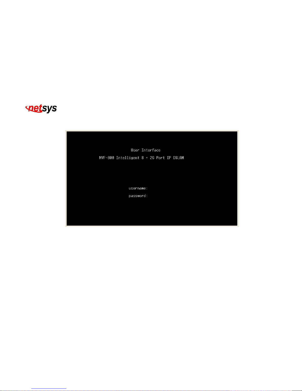
4.1.1.7 Logout
Exit this user interface program.(Figure 4.59)
Figure 4.59 Logout
Page 86

NVF-800S 4-Band VDSL IP DSLAM USER’S MANUAL Ver_B.2
85
4.2 Remote Network Management
4.2.1 IP Setting
Setup the “IP Address” with the local serial console port (RS-232 Port) then use this IP address to control the VDSL IP
DSLAM by Telnet and WEB. Then use the default IP address to control this VDSL IP DSLAM.
1. Remote control by “Telnet”
To enter Telnet, type the IP address of the NVF-800S to connect management system then type User name and
Password.
Default User Name: admin
Default Password: 123
Note:
1. For security reason, we limit the user login number on Telnet and Console port. So you can’t login Telnet and
Console port at the same time. But you can login Telnet and Console port at the different time.
2. WEB Login doesn’t limit user login numbers.
When you want to close console port control you must log-out to leave. Otherwise you can’t login by Telnet.
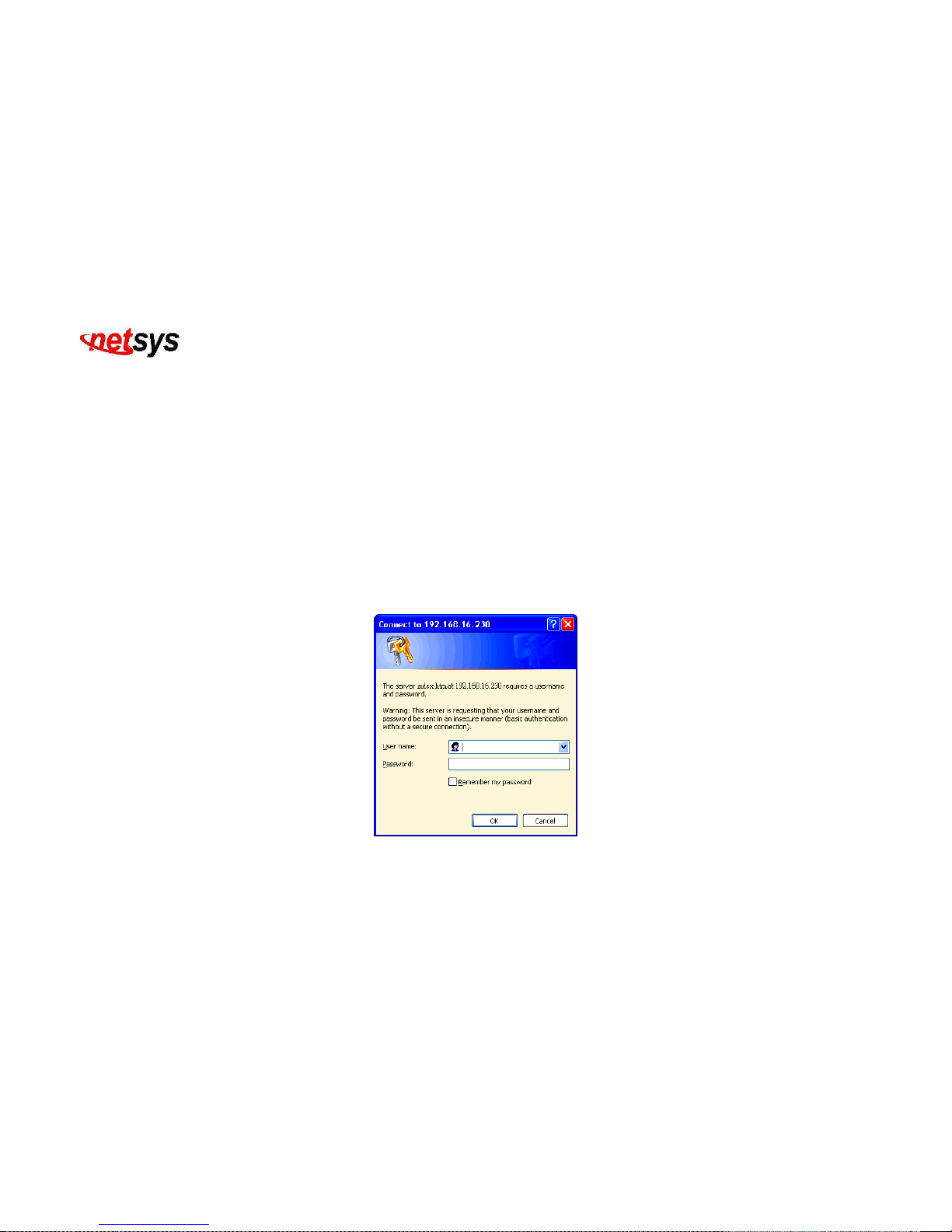
2. Network control by “WEB”
Page 87
NVF-800S 4-Band VDSL IP DSLAM USER’S MANUAL Ver_B.2
86
4.2.2 Web Management Function
1. Provide a Web browser to manage and monitor the NVF-800S, the default values as follows:
If you need change IP address in first time, use console mode to modify it.
IP Address: 192.168.16.250
Subnet Mask: 255.255.255.0
Default Gateway: 192.168.16.1
User Name: admin
Password: 123
2. Browse “http:// 192.168.16.250”, type user name and password as above. (Figure 4.60)
Figure 4.60 Username & Password
Page 88
NVF-800S 4-Band VDSL IP DSLAM USER’S MANUAL Ver_B.2
87
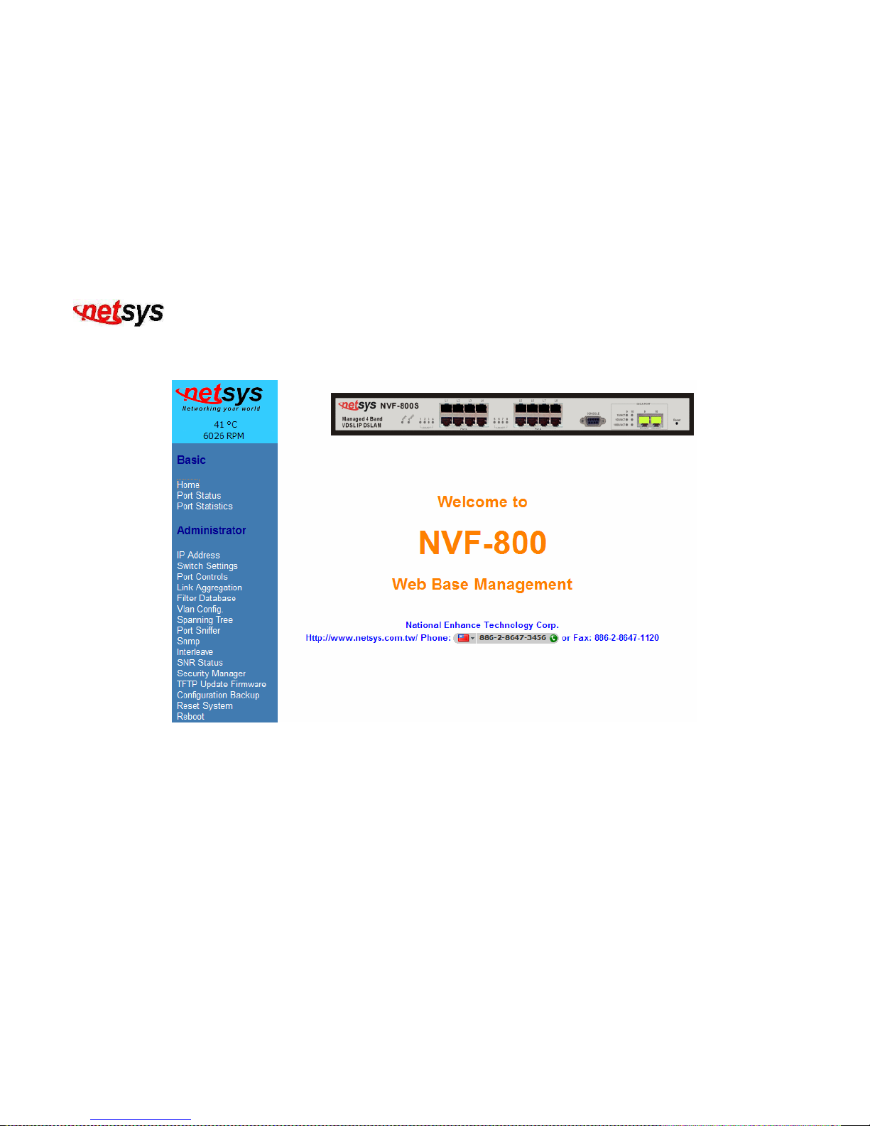
4.2.2.1 Web Management Home Overview
This is VDSL Home Page. (Figure 4.61)
Figure 4.61 Web Base Management
Page 89
NVF-800S 4-Band VDSL IP DSLAM USER’S MANUAL Ver_B.2
88
4.2.2.2 Port Status
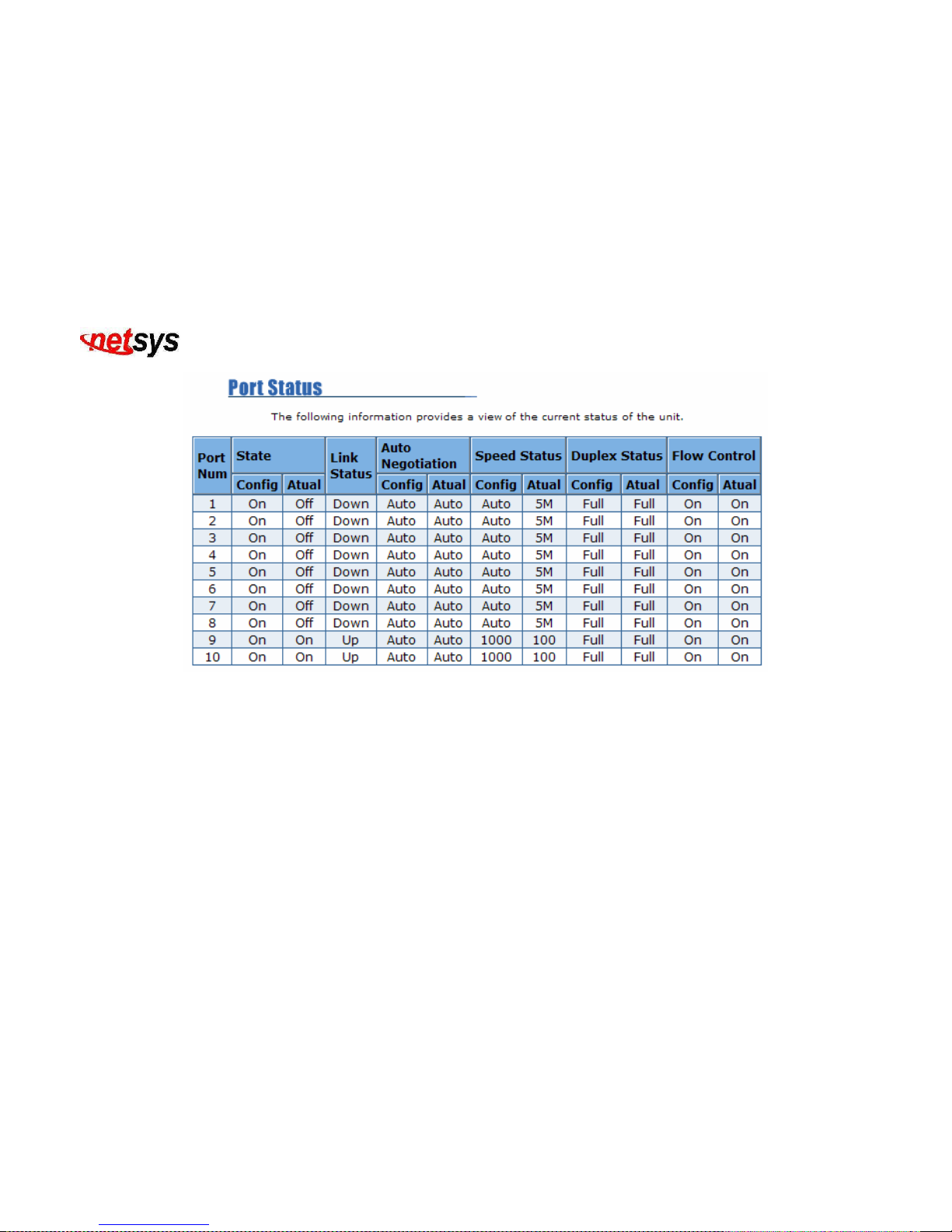
1. This page can see the status of every port. (Figure 4.62)
Item Description
State:
Display port status enable or disable state, where enable is link port and disable is no link port.
Config: Display the user setup setting On when enable and Off when disable.
Actual: Display the negotiation result.
Link Status:
Down is “No Link”, Up is “Link”
Auto Negotiation:
NVF-800S auto negotiation mode
Configure: Display the user setup of auto negotiation mode.
Actual: Display the negotiation result.
Speed status:
Port 9、10 are 10/100/1000Mbps or and Port 1- 8 are 5/15/25Mbps.
Configure: Display the state of user setup.
Actual: Display the negotiation result.
Duplex status:
Display full-duplex or half-duplex mode.
Configure: Display the user setup.
Actual: Display the negotiation result.
Flow control:
Display flow control status enable or disable mode.
Configure: Display the user setup.
Actual: Display the negotiation result.
Page 90
NVF-800S 4-Band VDSL IP DSLAM USER’S MANUAL Ver_B.2
89
Figure 4.62 Port Status
Page 91
NVF-800S 4-Band VDSL IP DSLAM USER’S MANUAL Ver_B.2
90
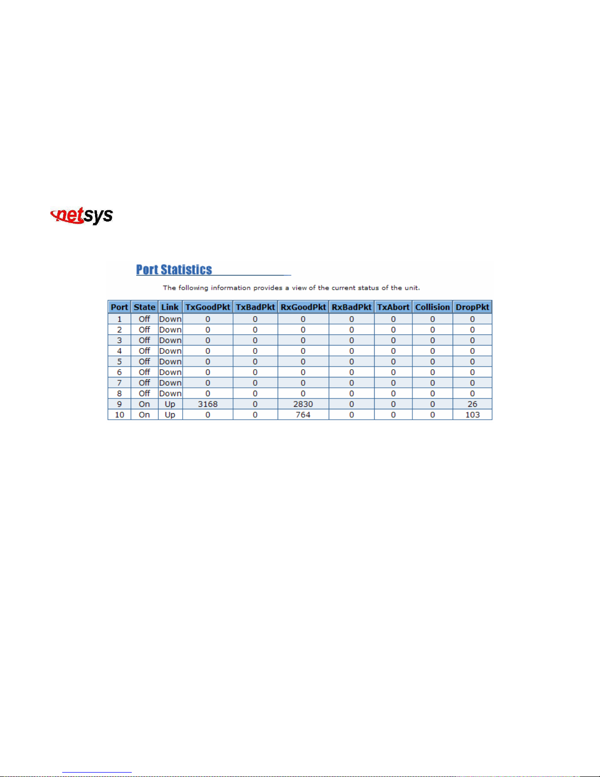
4.2.2.3 Port Statistics
1. The following information provides a view of the current status of the unit. (Figure 4.63)
Figure 4.63 Port Statistics
Page 92

NVF-800S 4-Band VDSL IP DSLAM USER’S MANUAL Ver_B.2
91
4.2.2.4 Administrator
There are many management functions include:
IP Address: Set IP Addresses. See section 4.2.2.4.1
Switch Setting: See section 4.2.2.4.2
Console Port Information: See section 4.2.2.4.3
Port Controls: See section 4.2.2.4.4
Link Aggregation: See section 4.2.2.4.5
Filter Database: See section 4.2.2.4.6
VLAN Config.: See section 4.2.2.4.7
Spanning Tree: See section 4.2.2.4.8
Port Sniffer: See section 4.2.2.4.9
SNMP: See section 4.2.2.4.10
Interleave: See section 4.2.2.4.11
SNR Status: See section 4.2.2.4.12
Security Manager: See section 4.2.2.4.13
TFTP Update Firmware: See section 4.2.2.4.14
Configuration Backup: See section 4.2.2.4.15
Restart System: See section 4.2.2.4.16
Reboot: See section 4.2.2.4.17
Page 93
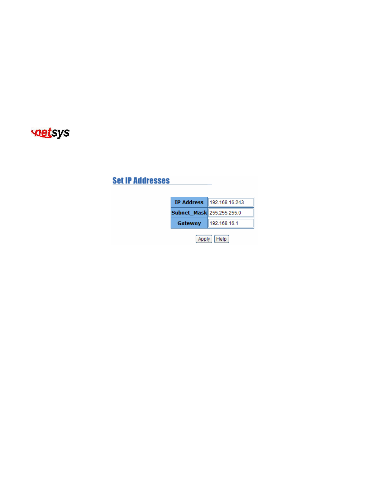
NVF-800S 4-Band VDSL IP DSLAM USER’S MANUAL Ver_B.2
92
4.2.2.4.1 IP Address
1. User can configure the IP Settings and fill in the new value, then click the apply button.
2. User must reset NVF-800S and use new IP address to browse this web management. (Figure 4.64)
Figure 4.64 Default IP is 192.168.16.250
Page 94
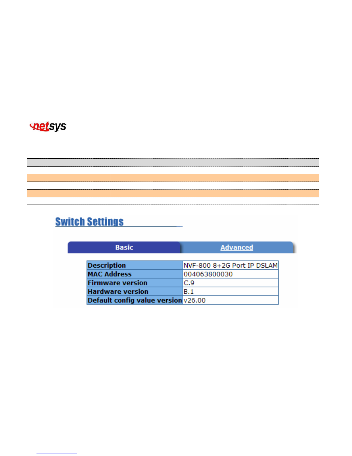
NVF-800S 4-Band VDSL IP DSLAM USER’S MANUAL Ver_B.2
93
4.2.2.4.2 NVF-800S Settings
4.2.2.4.2.1 Basic
(Figure 4.65)
Item Description
Description:
Display the device type.
MAC Address:
The unique hardware address assigned by manufacturer.
Firmware Version:
Display the NVF-800S firmware version.
Hardware Version:
Display the NVF-800S hardware version.
Default config value version:
Display write to default EEPROM value tale version.
Figure 4.65 Switch Settings Basic
Page 95
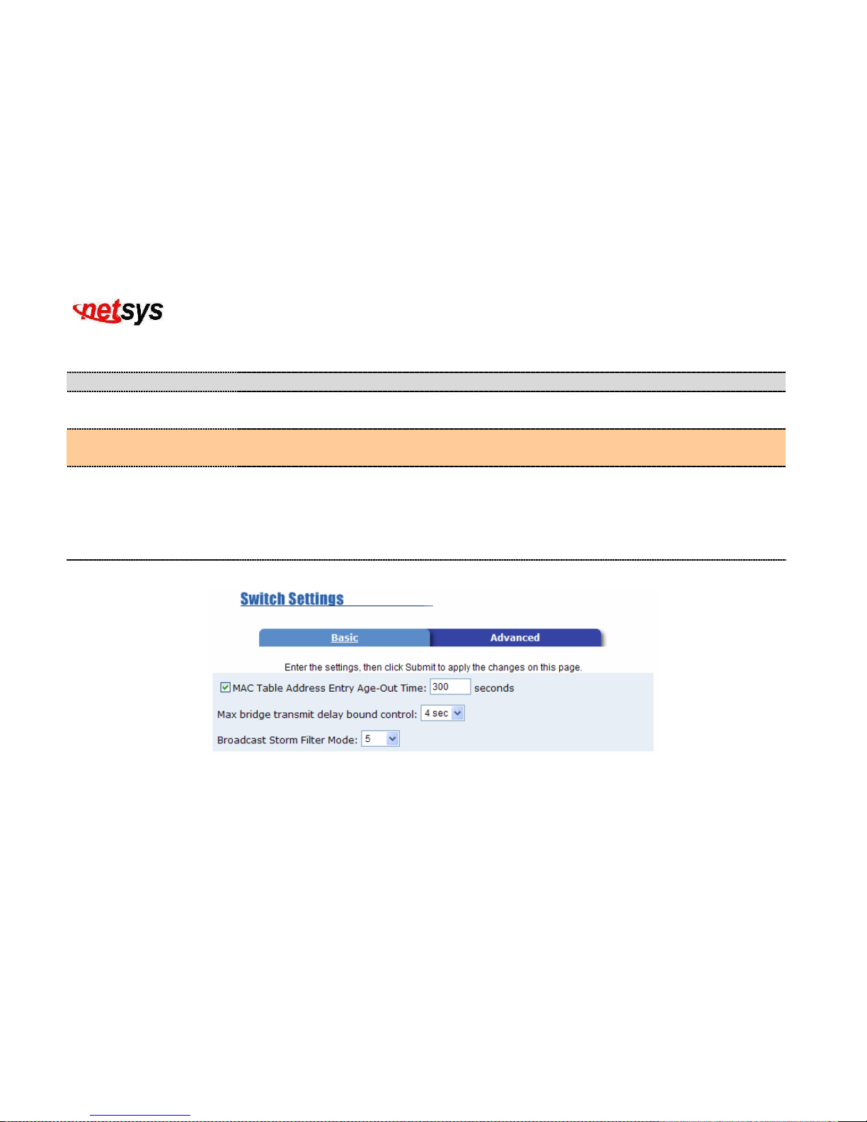
NVF-800S 4-Band VDSL IP DSLAM USER’S MANUAL Ver_B.2
94
4.2.2.4.2.2 Advanced
Miscellaneous Setting: (Figure 4.66)
Item Description
MAC Address Age-out
Time:
Type the number of seconds that an inactive MAC address will remain in the NVF-800S
address table. The valid range is 300~765 seconds. Default is 300 seconds.
Max bridge transit delay
bound control:
Limit the packets queuing time in NVF-800S. If enable, the packets will be drop if exceed
the queued time. The valid values are 1sec, 2 sec, 4 sec and off. Default is 4 seconds.
Broadcast Storm Filter:
To configure broadcast storm filter, set the upper threshold for individual ports. The
threshold is the percentage of the port's total bandwidth used by broadcast traffic. When
broadcast traffic for a port rises above the threshold being set, broadcast storm filter
becomes active. The valid threshold values are 5%, 10%, 15%, 20%, 25% and off. The
default value is 5%.
Figure 4.66 Switch Settings Advanced (Miscellaneous Setting)
Page 96
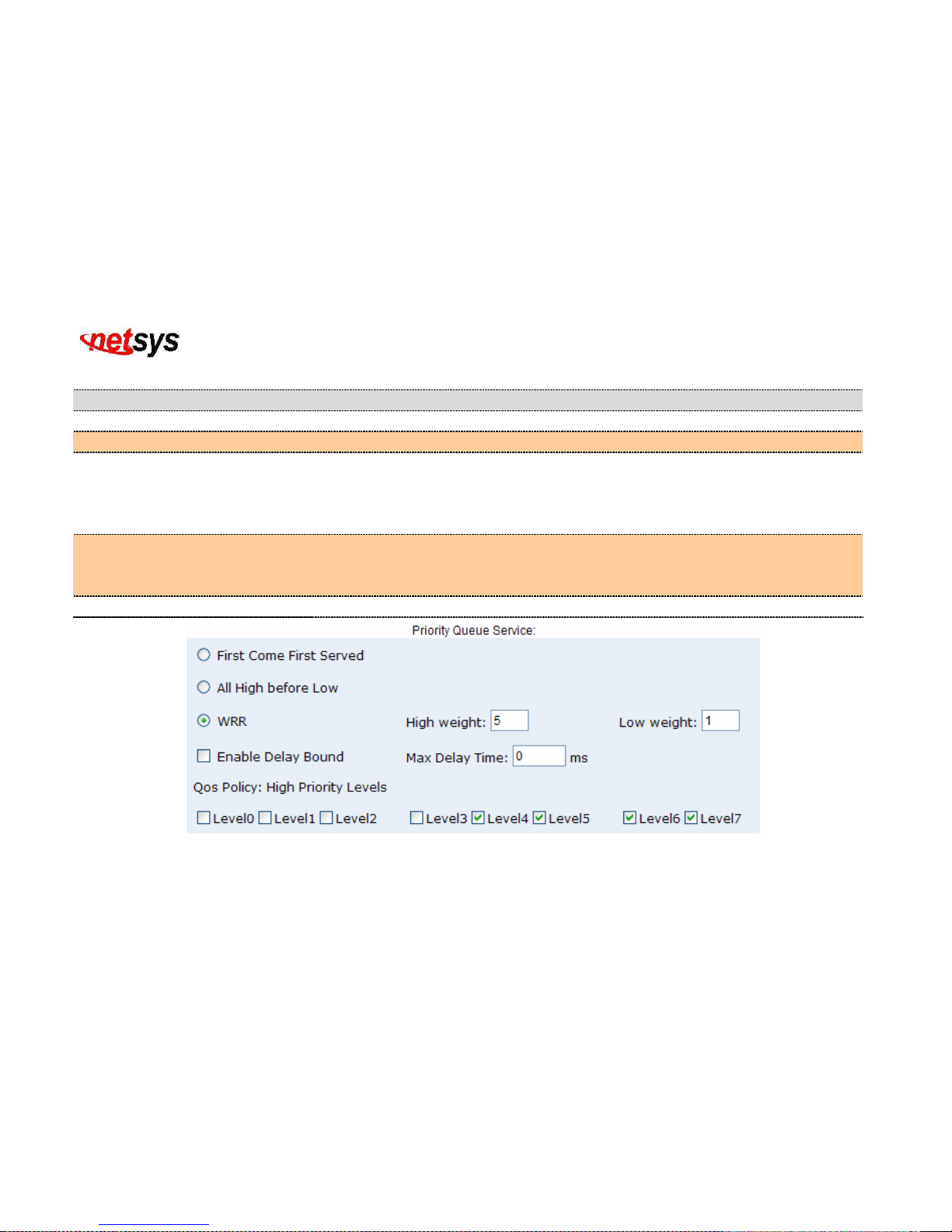
NVF-800S 4-Band VDSL IP DSLAM USER’S MANUAL Ver_B.2
95
Priority Queue Service settings: (Figure 4.67)
Item Description
First Come First Served:
The sequence of packets sent depends on arrived order.
All High before Low:
The high priority packets are sent before low priority packets.
Weighted Round Robin:
Select the preference given to packets in the NVF-800S high-priority queue.
These options represent the number of high priority packets sent before one low
priority packet is sent. For example 5 High : 2 Low means that the NVF-800S sends
5 high priority packets before sending 2 low priority packet.
Enable Delay Bound:
Limit the low priority packets queuing time in NVF-800S. Default Max Delay Time is
255ms. If the low priority packet stays in NVF-800S exceed Max Delay Time, it will
be sent. The valid range is 1~255 ms.
QoS Policy: High Priority Levels:
0~7 priority level can map to high or low queue.
Figure 4.67 Priority Queue Service
Page 97
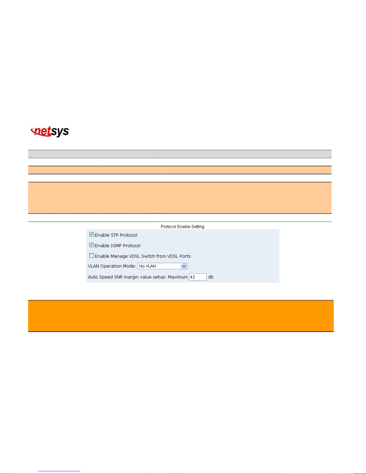
NVF-800S 4-Band VDSL IP DSLAM USER’S MANUAL Ver_B.2
96
Protocol Enable Setting: (Figure 4.68)
Item Description
Enable Spanning Tree Protocol:
Default recommends enable STP
Enable Internet Group Multicast Protocol:
Default recommends enable IGMP protocol
Enable Manage VDSL Switch from VDSL Ports:
Enable manage VDSL IPDSLAM from port 1~8
VLAN Operation Mode:
No VLAN
802.1Q(Tagging Based) without GVRP
802.1Q(Tagging Based) with GVRP
Port Based VLAN
Auto Speed SNR Margin Maximun Value setup:
Auto Speed SNR Margin Maximun Value must be 35 ~ 50
Figure 4.68 Protocol Enable Setting
Tip:
GVRP (GARP [Generic Attribute Registration Protocol] VLAN Registration Protocol)
GVRP allows automatic VLAN configuration between the NVF-800S and nodes. If the NVF-800S is connected to a
device with GVRP enabled, you can send a GVRP request using the VID of a VLAN defined on the NVF-800S, the
NVF-800S will automatically add that device to the existing VLAN.
Page 98

NVF-800S 4-Band VDSL IP DSLAM USER’S MANUAL Ver_B.2
97
4.2.2.4.3 Console Port Information
Console is a standard UART interface to communicate with Serial Port.
User can use windows HyperTerminal program to link the NVF-800S. Connect To->Configure
Bits per seconds:
9600
Data bits:
8
Parity:
none
Stop bits:
1
Flow control:
none
4.2.2.4.4 VDSL Speed Control and port Enable/Disable
This section shows you how to change every port status and speed mode. (Figure 4.69)
Item Description
State:
You can disable or enable VDSL port control
Auto Negotiation:
You can set enable or disable VDSL port
Speed:
You can change VDSL Speed mode by 5Mbps, 15Mbps or 25Mbps. Speed Default Value: Auto-speed
Duplex:
User can set full-duplex or half-duplex mode for Ethernet port. VDSL port fixed on Full Duplex.
Full: User can set flow control function enable or disable in full mode.
Flow Control:
Half: User can set backpressure enable or disable in half mode.
Auto Speed procedures:
a. Confirm the phone cable been connected for both NVF-800S and NVF-200R.
b. Powered on NVF-800S and NVF-200R.
Page 99
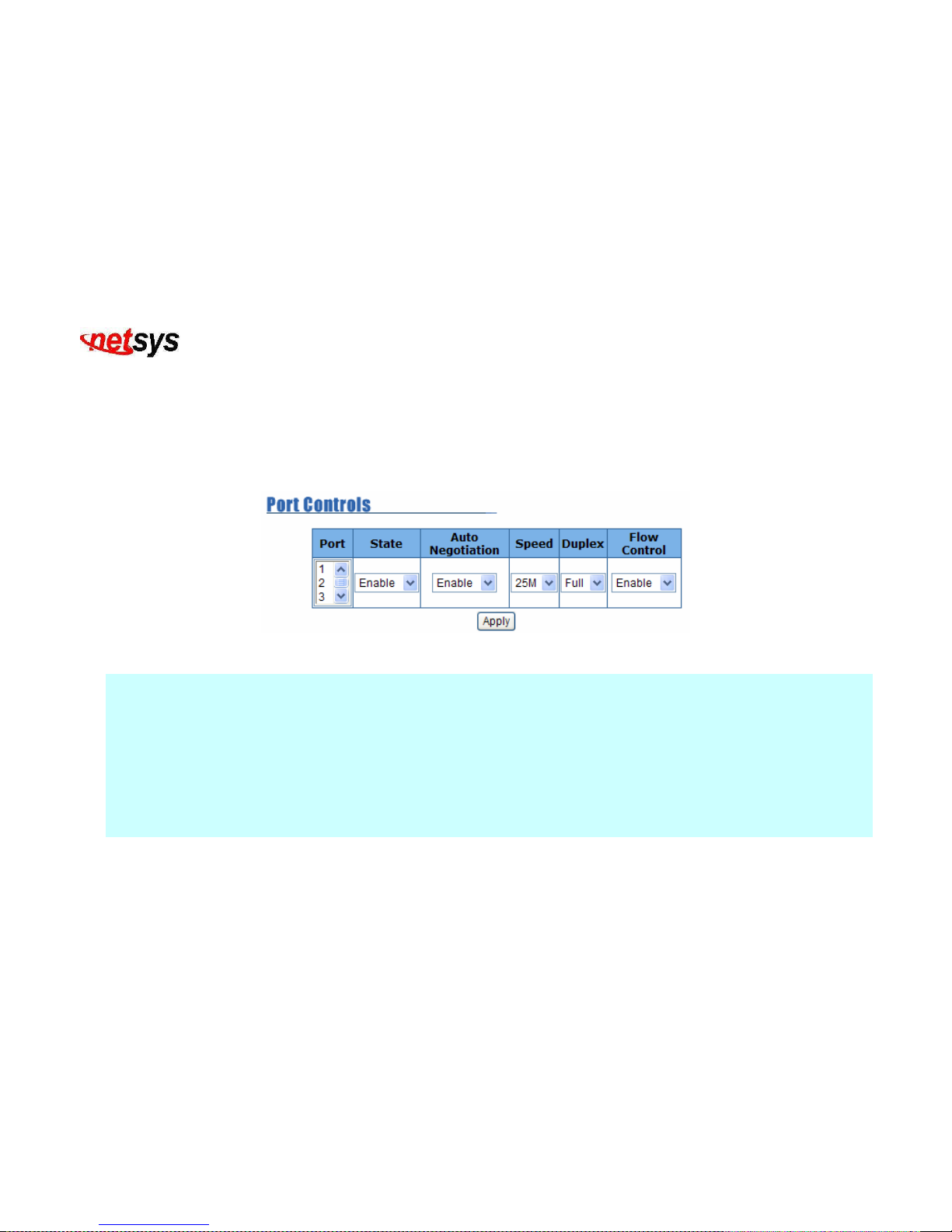
NVF-800S 4-Band VDSL IP DSLAM USER’S MANUAL Ver_B.2
98
c. Start auto-speed function after NVF-200R reboots.
d. NVF-800S will try to link at 25M mode with NVF-200R. If it fails, auto-speed goes down to 15M mode and re-link
with NVF-200R. If it fails again, auto-speed goes down to 5M and keeps this mode then re-link with NVF-200R.
e. Please note any length of phone cable change, NVF-200R must re-powered again due to auto-speed function work
only when restarting.
f. Await 5 ~ 120 seconds until VDSL port link up where it depends on phone cable length.
Figure 4.69 Port Controls
Note:
VDSL port supports auto-speed mode, the speed mode depends on phone cable length and crosstalk issues, anytime
auto-speed starts on, phone cable must be re-plugged and NVF-800S must be re-powered on, wait for a few minutes
auto-speed to link.
25M/25M symmetric run up to 600 meters (without PBX)
15M/15M symmetric run up to 1.1km (without PBX)
5M/5M symmetric run up to 1.7km (without PBX)
The performance data above is for reference only, the actual distance will vary on the quality of the copper wire and environment
factors. With above speed mode testing based on 24gauge twisted pair phone cable without PBX.
Page 100
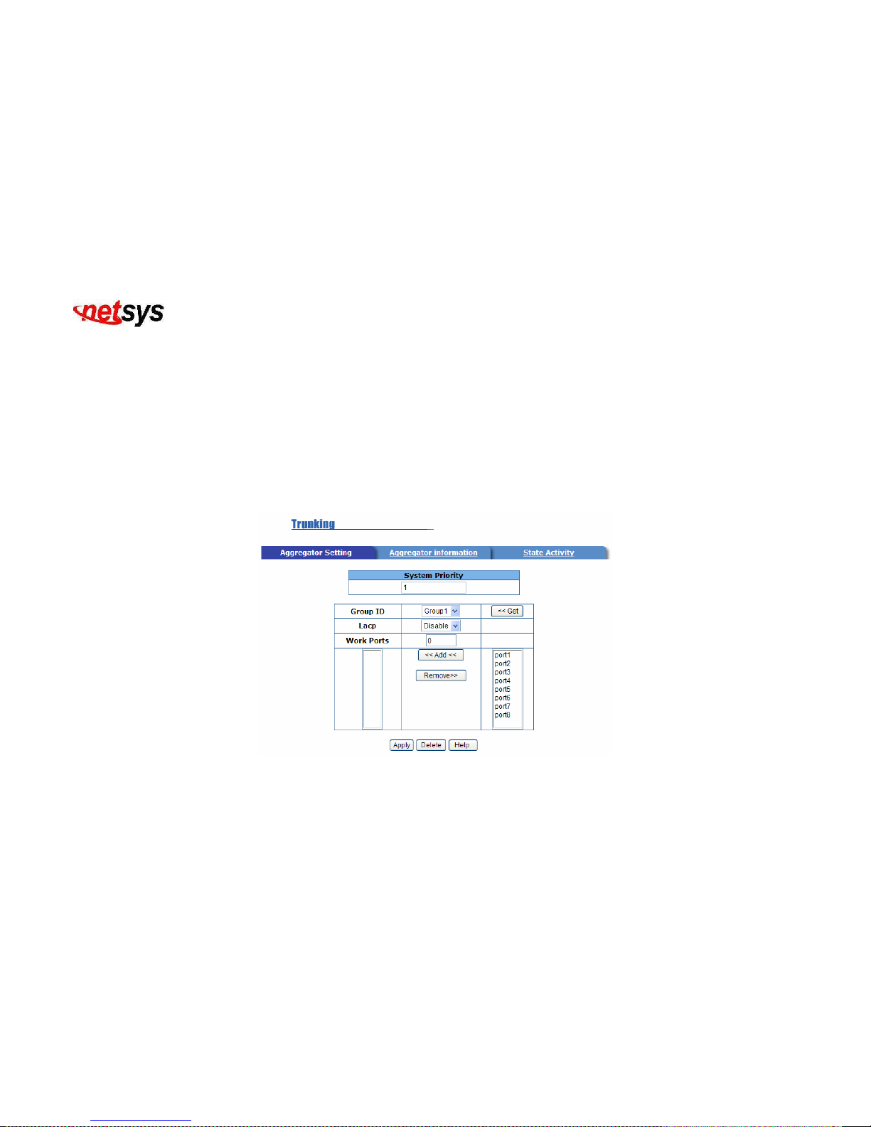
NVF-800S 4-Band VDSL IP DSLAM USER’S MANUAL Ver_B.2
99
4.2.2.4.5 Link Aggregation
The Link Aggregation Control Protocol (LACP) provides a standardized means for exchanging information between
Partner Systems on a link to allow their Link Aggregation Control instances to reach agreement on the identity of the Link
Aggregation Group to which the link belongs, to move the link to that Link Aggregation Group and enable its transmission
and reception functions in an orderly manner. Therefore, Link aggregation lets you group up to eight consecutive ports into
a single dedicated connection. This feature can expand bandwidth to a device on the network. LACP operation requires
full-duplex mode, for more detail information, please refer to IEEE 802.3ad.
4.2.2.4.5.1 Aggregator setting
Figure 4.70 Trunking(Aggregator Setting)
 Loading...