

Page 1

N
V
-
7
0
0
L
N
V
-
7
0
0
N
V
-
7
0
0
L
L
V
D
S
L
2
S
i
n
g
l
e
M
a
s
t
e
r
M
o
d
e
m
V
D
S
L
2
S
i
n
g
l
e
M
a
s
t
e
r
M
o
d
V
D
S
L
2
S
i
n
g
l
e
M
a
s
t
e
r
M
o
U
S
E
R
’
S
M
A
N
U
U
U
S
S
E
E
R
R
’
’
S
S
M
M
A
A
N
N
U
U
A
A
A
d
L
L
L
e
e
m
m
Page 2

NV-700L VDSL2 Single Master Modem USER’S MANUAL Ver. A.2
Copyright
Copyright © 2018 by National Enhance Technology Corp. All rights reserved.
Trademarks
NETSYS is a trademark of National Enhance Technology Corp.
Other brand and product names are registered trademarks or trademarks of their respective holders.
Legal Disclaimer
The information given in this document shall in no event be regarded as a guarantee of conditions or characteristics. With respect
to any examples or hints given herein, any typical values stated herein and/or any information regarding the application of the
device, National Enhance Technology Corp. hereby disclaims any and all warranties and liabilities of any kind, including without
limitation warranties of non-infringement of intellectual property rights of any third party.
Statement of Conditions
In the interest of improving internal design, operational function, and/or reliability, NETSYS reserves the right to make changes to
the products described in this document without notice. NETSYS does not assume any liability that may occur due to the use or
application of the product(s) or circuit layout(s) described herein.
Maximum signal rate derived from IEEE Standard specifications. Actual data throughput will vary. Network conditions and
environmental factors, including volume of network traffic, building materials and construction, and network overhead, lower actual
data throughput rate. Netsys does not warrant that the hardware will work properly in all environments and applications, and makes
no warranty and representation, either implied or expressed, with respect to the quality, performance, merchantability, or fitness for
a particular purpose. Make sure you follow in line with the environmental conditions to use this product.
1
Page 3

NV-700L VDSL2 Single Master Modem USER’S MANUAL Ver. A.2
Safety Warnings
For your safety, be sure to read and follow all warning notices and instructions before using the device.
DO NOT open the device or unit. Opening or removing the cover may expose you to dangerous high voltage points or other
risks. ONLY qualified service personnel can service the device. Please contact your vendor for further information.
Use ONLY the dedicated power supply for your device. Connect the power to the right supply voltage (110V AC used for
North America and 230V AC used for Europe. NV-700L supports 12 VDC power input).
Place connecting cables carefully so that no one will step on them or stumble over them. DO NOT allow anything to rest on
the power cord and do NOT locate the product where anyone can work on the power cord.
DO NOT install nor use your device during a thunderstorm. There may be a remote risk of electric shock from lightning.
DO NOT expose your device to dampness, dust or corrosive liquids.
DO NOT use this product near water, for example, in a wet basement or near a swimming pool.
Connect ONLY suitable accessories to the device.
Make sure to connect the cables to the correct ports.
DO NOT obstruct the device ventilation slots, as insufficient air flow may harm your device.
DO NOT place items on the device.
DO NOT use the device for outdoor applications directly, and make sure all the connections are indoors or have waterproof
protection place.
Be careful when unplugging the power, because it may produce sparks.
Keep the device and all its parts and accessories out of the reach of children.
Clean the device using a soft and dry cloth rather than liquid or atomizers. Power off the equipment before cleaning it.
This product is recyclable. Dispose of it properly.
2
Page 4
NV-700L VDSL2 Single Master Modem USER’S MANUAL Ver. A.2
Attention:
Be sure to read this manual carefully before using this product. Especially Legal Disclaimer, Statement
of Conditions and Safety Warnings.
NV-700L is a VDSL2 Master Modem that leverages the extraordinary bandwidth promise of VDSL2 (max. 100Mbps symmetric)
technology, the next step in the delivery of new high-speed Internet applications in commercial environments. Quick, easy,
economical to install and maintain, the NV-700L works over existing copper wire infrastructure. NV-700L is a CO(Central Office)
device. And compitable with the NV-720R CPE(Customer-premises equipment).
NV-700L will allow operators worldwide to compete with cable andsatellite operators by offering services such as HDTV, VOD,
videoconferencing, high speed Internet access and advanced voice services including VoIP, over a standard copper
telephone cable. NV-700L is seen by many operators as an ideal accompaniment to a FTTP rollout, where for instance fiber optic is
supplied direct to an apartment block and from there copper cable is used to supply residents with high-speed VDSL2.
Caution:
The NV-700L is for indoor applications only. This product does not have waterproof protection, please do not use in outdoor
applications.
3
Page 5

NV-700L VDSL2 Single Master Modem USER’S MANUAL Ver. A.2
Table of Contents
COPYRIGHT.......................................................................................................................................................................................................................................................... 1
1.1 C
HECK LIST
CHAPTER 2. INSTALLING THE MODEM ........................................................................................................................................................................................................ 8
2.1 H
ARDWARE INSTALLATION
2.2 PRE-
2.3 G
2.4 C
2.5 VDSL2 A
CHAPTER 3. HARDWARE DESCRIPTION ................................................................................................................................................................................................... 13
3.1 F
3.2 F
3.3 R
CHAPTER 4. CONFIGURE THE NV-700L VIA WEB BROWSER............................................................................................................................................................... 18
INSTALLATION REQUIREMENTS
ENERAL RULES
ONNECTING THE
PPLICATION
RONT PANEL
RONT INDICATORS
EAR PANEL
.................................................................................................................................................................................................................................................... 7
............................................................................................................................................................................................................................. 8
................................................................................................................................................................................................................ 8
............................................................................................................................................................................................................................................. 9
RJ-11 / RJ-45 P
.................................................................................................................................................................................................................................. 11
................................................................................................................................................................................................................................................ 14
....................................................................................................................................................................................................................................... 14
............................................................................................................................................................................................................................................... 16
ORTS
........................................................................................................................................................................................................ 10
4.1 BASIC S
Login webpage.......................................................................................................................................................................................................................................... 19
Display status............................................................................................................................................................................................................................................ 20
4.2 S
YSTEM SETUP
System–> Configuration Backup ......................................................................................................................................................................................................... 21
System-> Configuration Restore.......................................................................................................................................................................................................... 22
System->Update Software ..................................................................................................................................................................................................................... 23
ETUP
............................................................................................................................................................................................................................................ 19
........................................................................................................................................................................................................................................... 21
4
Page 6

NV-700L VDSL2 Single Master Modem USER’S MANUAL Ver. A.2
system->Account Management ............................................................................................................................................................................................................ 24
system->Account Management - Log Level ...................................................................................................................................................................................... 25
System->Service control ........................................................................................................................................................................................................................ 26
System->CWNP->TR-069 Settings ....................................................................................................................................................................................................... 27
System->Restore Default Setting ......................................................................................................................................................................................................... 29
4.3 S
TATUS SETUP
Status ->LAN Network............................................................................................................................................................................................................................. 30
Status->LAN-> Ethernet.......................................................................................................................................................................................................................... 31
Status->WAN Statistics........................................................................................................................................................................................................................... 32
Status->LAN Statistics............................................................................................................................................................................................................................ 33
Status->ARP .............................................................................................................................................................................................................................................. 34
4.4 X
DSL
SETUP.............................................................................................................................................................................................................................................. 35
Xdsl ->DSL STATUS ................................................................................................................................................................................................................................. 35
Xdsl-DSL Config ....................................................................................................................................................................................................................................... 36
VDSL Config Overview............................................................................................................................................................................................................................ 37
4.5 LAN S
LAN >IPV4 Configuration ....................................................................................................................................................................................................................... 38
ETUP
............................................................................................................................................................................................................................................ 30
................................................................................................................................................................................................................................................. 38
LAN->IPv6 Configuration: ...................................................................................................................................................................................................................... 39
4.6 Q
OS
SETUP ............................................................................................................................................................................................................................................... 40
Qos ->Qos Queue..................................................................................................................................................................................................................................... 40
4.7 A
PPLICATION SETUP
Application->Telnet Service Setup ...................................................................................................................................................................................................... 41
Application-> SSH Service ..................................................................................................................................................................................................................... 42
Application->Printer Share .................................................................................................................................................................................................................... 43
................................................................................................................................................................................................................................... 41
5
Page 7

NV-700L VDSL2 Single Master Modem USER’S MANUAL Ver. A.2
Application->Multimedia Share ............................................................................................................................................................................................................ 44
Application->Dynamic DNS ................................................................................................................................................................................................................... 45
Application->UPnP................................................................................................................................................................................................................................... 46
Application->multicast IGMP setting .................................................................................................................................................................................................. 47
Application->Multicast MLD .................................................................................................................................................................................................................. 48
APPLICATION->SNMP ............................................................................................................................................................................................................................ 49
4.8 USB
APPENDIX A: CABLE REQUIREMENTS ...................................................................................................................................................................................................... 58
APPENDIX B: PRODUCT SPECIFICATION.................................................................................................................................................................................................. 61
APPENDIX C: TROUBLESHOOTING ............................................................................................................................................................................................................ 65
SETUP
USB-Storage Device Info........................................................................................................................................................................................................................ 52
USB->Samba Service .............................................................................................................................................................................................................................. 53
USB-> FTP Server .................................................................................................................................................................................................................................... 54
USB-> FTP Client...................................................................................................................................................................................................................................... 55
USB-> TFTP Server .................................................................................................................................................................................................................................. 57
................................................................................................................................................................................................................................................. 52
APPENDIX E: COMPLIANCE INFORMATION ............................................................................................................................................................................................ 73
WARRANTY......................................................................................................................................................................................................................................................... 76
CHINESE SJ/T 11364-2014............................................................................................................................................................................................................................... 77
6
Page 8
Chapter 1. Unpacking Information
1.1 Check List
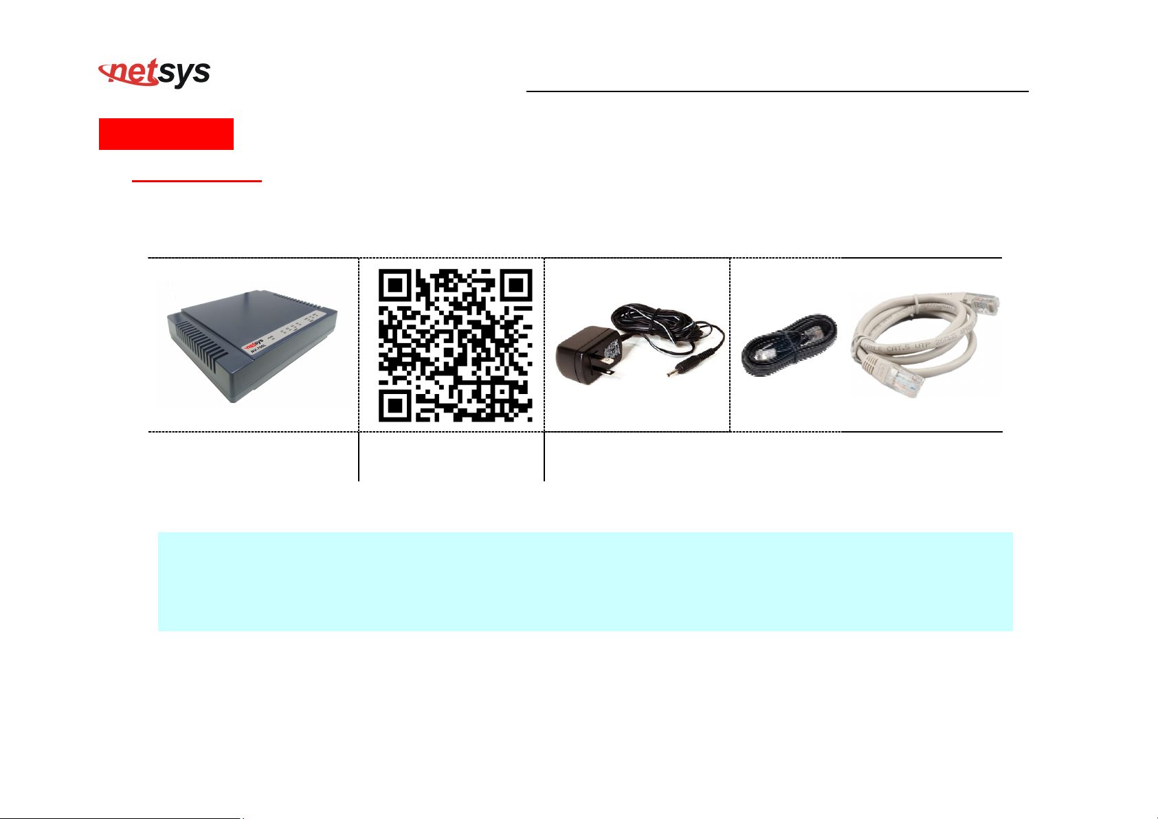
Thank you for choosing Netsys NV-700L Before installing the router, please verify the contents inside the package.
NV-700L VDSL2 Single Master Modem USER’S MANUAL Ver. A.2
Package Contents:
1 x VDSL2 CO Modem 1 x QR code for user’s
Notes:
1. Please inform your dealer immediately for any missing or damaged parts. If possible, retain the carton including the
original packing materials. Use them to repack the unit in case there is a need to return for repair.
2. Do not use sub-standard power supply. Before connecting the power supply to the device, be sure to check
compliance with the specifications. The NV-700L uses a DC12V/1A or above Switching power supply.
Accessory Kit : 1 x Ethernet Cable, 1 x Phone wire , 1 x
manual hyperlink.
DC12V Power Adapter
7
Page 9

Chapter 2. Installing the Modem
2.1 Hardware Installation
This chapter describes how to install the modem, and establish the network connections. The NV-700L may be
installed on any level surface (e.g. a table or shelf). However, please take note of the following minimum site
requirements before you begin. The NV-700L has 2 pre-installed rubber feet.
2.2 Pre-installation Requirements
Before you start the actual hardware installation, make sure you can provide the right operating environment, including
power requirements, sufficient physical space, and proximity to other network devices that are to be connected.
Verify the following installation requirements:
• Power requirements: DC 12 V / 1A
NV-700L VDSL2 Single Master Modem USER’S MANUAL Ver. A.2
• The modem should be located in a cool dry place, with at least 10cm/4in of space at the front and back for
ventilation.
• Place the modem away from direct sunlight, heat sources, or areas with a high amount of electromagnetic
interference.
• Check if the network cables and connectors needed for installation are available.
• Do not install phone lines strapped together with AC power lines, or telephone office line with voice signal.
• Avoid installing this device with radio amplifying stations nearby or transformer stations nearby.
• Please note that the voice spectrum allowed by the NV-700L internal splitter is 0 KHz ~ 120 KHz.
8
Page 10
2.3 General Rules
Before making any connections to the modem, please note the following rules:
• Ethernet Port interface : RJ-45
• VDSL2 Port interface : RJ-11 & Terminal block combo
NV-700L VDSL2 Single Master Modem USER’S MANUAL Ver. A.2
All network connections to the modem Ethernet port must be made using Category 5 UTP/STP or above for
100 Mbps, Category 3, 4 UTP for 10Mbps.
No more than 100 meters of cabling may be use between the MUX or HUB and an end node.
All network connections to the RJ-11/ terminal block(sharing port) must use 24~26 gauge with single
twisted pair phone wire.
We do not recommend the use of the 28 gauge phone wire or above.
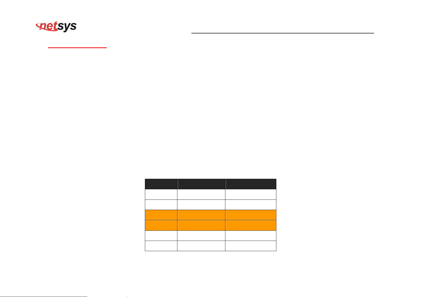
The RJ-11 is an 6P2C connector, two of which are wired. The modem uses the center two pins. The pin out
assignment for these connectors is presented below.
Please note that the line port is no polarity, therefore user can reverse the two wires of the phone cable
when installed.
RJ-11 Pin out Assignments
Pin# MNEMONIC FUNCTION
1 NC Unused
2 NC Unused
3 DSL Used
4 DSL Used
5 NC Unused
6 NC Unused
9
Page 11
NV-700L VDSL2 Single Master Modem USER’S MANUAL Ver. A.2
2.4 Connecting the RJ-11 / RJ-45 Ports
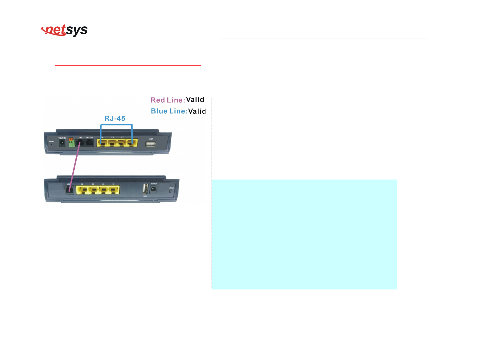
The line port have 1 connector: RJ-11 . It is used to connect with NV-700L (CO) over a single pair phone wire to NV-720R
CPE(Slave) side (point to point application). (Figure 2.1)
When inserting a RJ-11 plug, make sure the tab on the
plug clicks into position to ensure that it is properly
seated.
Do not plug a RJ-11 phone jack connector into the
Ethernet port (RJ-45 port). This may damage the
modem. Instead, use only twisted-pair cables with RJ-45
connectors that conform to Ethernet standard.
Notes:
1. Be sure each twisted-pair cable (RJ-45 Ethernet cable)
does not exceed 100 meters (333 feet).
2. We advise using Category 5~7 UTP/STP cables for
Figure 2.1 NV-700L line ports straight connection
making Ethernet connections to avoid any confusion or
inconvenience in the future when you attach high
bandwidth devices.
3. Use 24 ~ 26 gauge twisted pair phone wiring, we do not
recommend 28 gauge or above.
4. Be sure phone wire has been installed before the
NV-700L boot.
5. Do not connect Line port with RJ-11 and Terminal block
to two CPE modem.
10
Page 12
NV-700L VDSL2 Single Master Modem USER’S MANUAL Ver. A.2
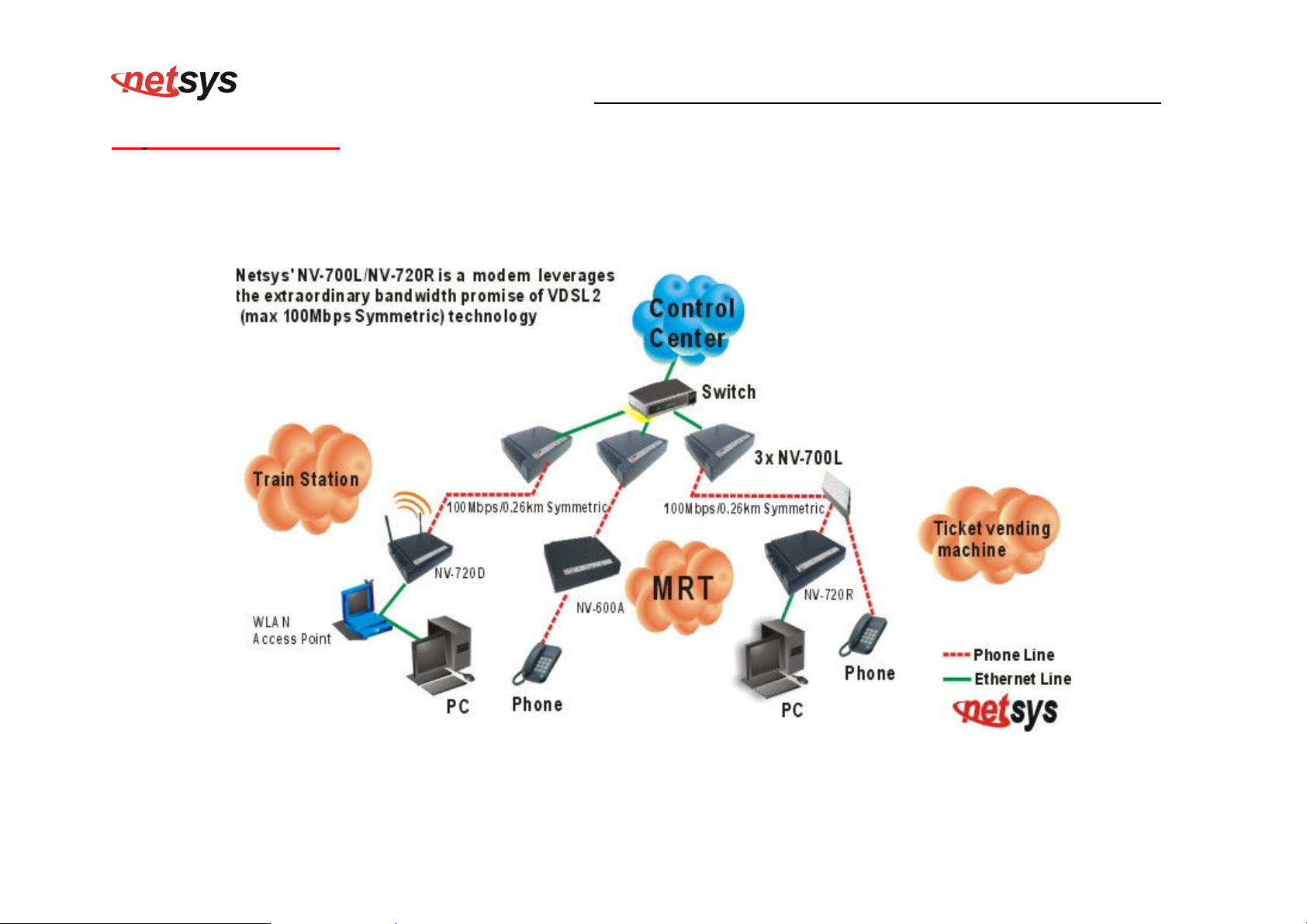
2.5 VDSL2 Application
First a quick overview on a complete setup of VDSL2 CO/CPE Modem.
NV-700L/NV-720R is a modem leverages the extraordinary bandwidth promise of VDSL2(max 100Mbps Symmetric) technology
(Figure 2.2)
Figure 2.2 NV-700L application
11
Page 13

NV-700L VDSL2 Single Master Modem USER’S MANUAL Ver. A.2
2.5.1 Connect the NV-700L and the NV-720R to the Line
The objective for VDSL2 is to pass high speed data over a twisted pair cable. In the setup, connect NV-700L to NV-720R through
phone wire(24~26 AWG) or line simulator or any other hardware representation of a cable network, with or without noise
injection and crosstalk simulations.
2.5.2 Connect the NV-700L and the NV-720R to LAN Devices
In the setup, usually an Ethernet tester serves as a representation of the LAN side as well as a representation of the WAN side.
2.5.3 Run Demos and Tests
The Ethernet tester may send data downstream as well as upstream. It also receives the data in order to check the integrity of the
data transmission. Different data rates can be tested under different line conditions
12
Page 14
NV-700L VDSL2 Single Master Modem USER’S MANUAL Ver. A.2
Chapter 3. Hardware Description
This section describes the important parts of the vdsl2 Modem It features the front panel and rear panel.
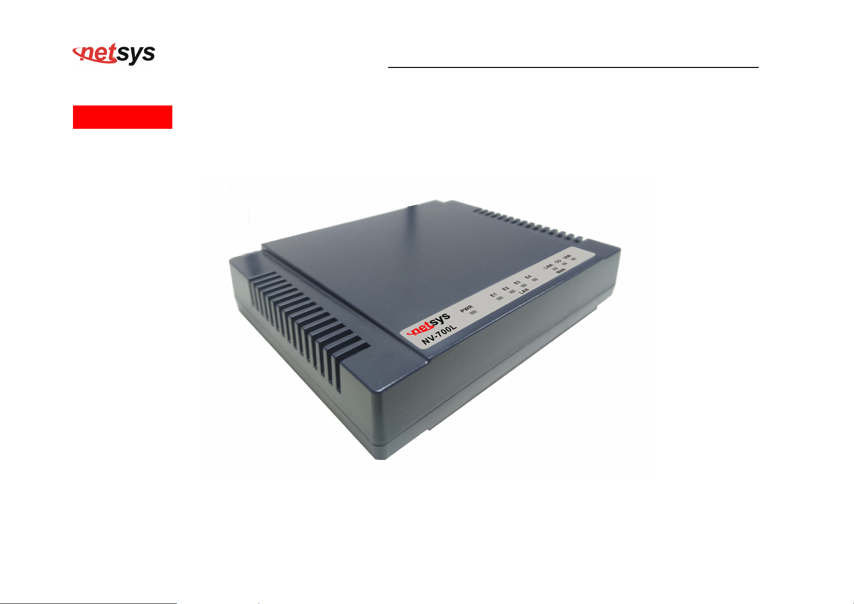
NV-700L Outward
13
Page 15
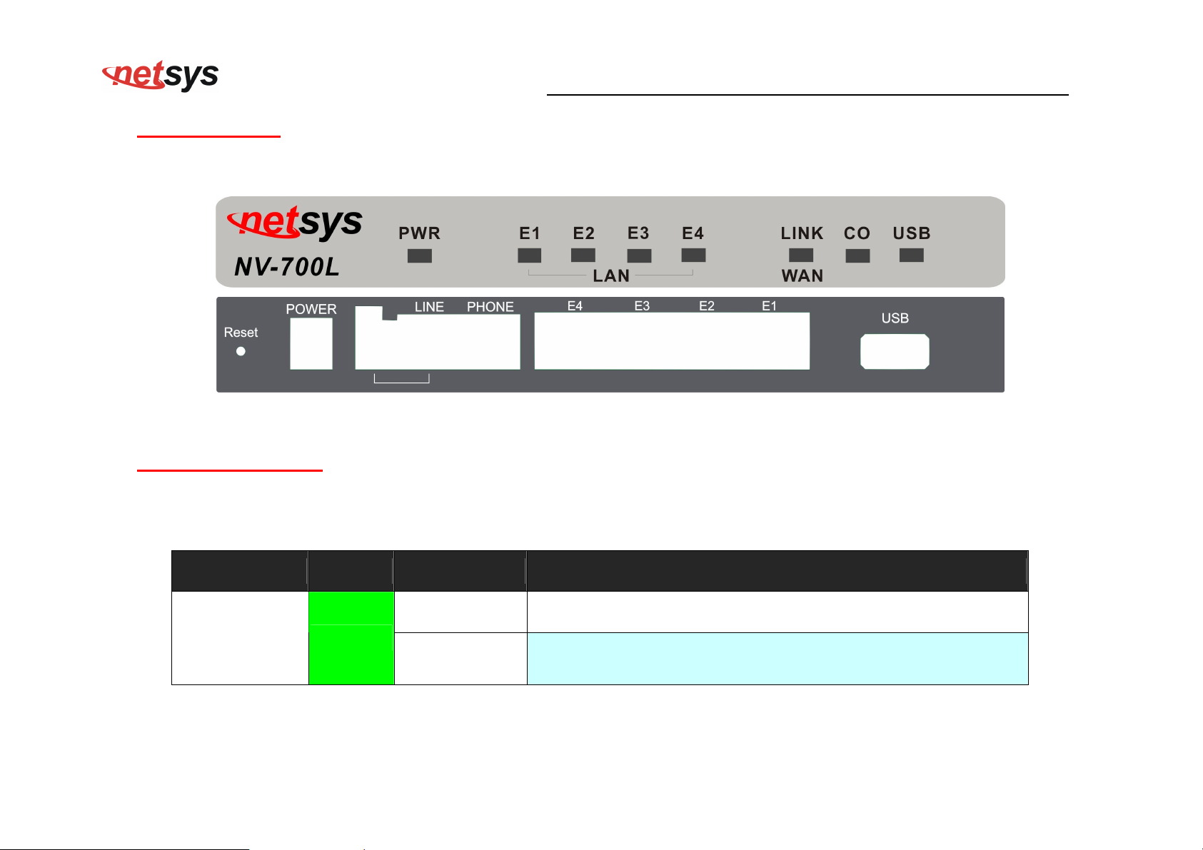
3.1 Front Panel
The figure shows the front panel. (Figure 3.1)
3.2 Front Indicators
NV-700L VDSL2 Single Master Modem USER’S MANUAL Ver. A.2
Figure 3.1 Front Panel(NV-700L)
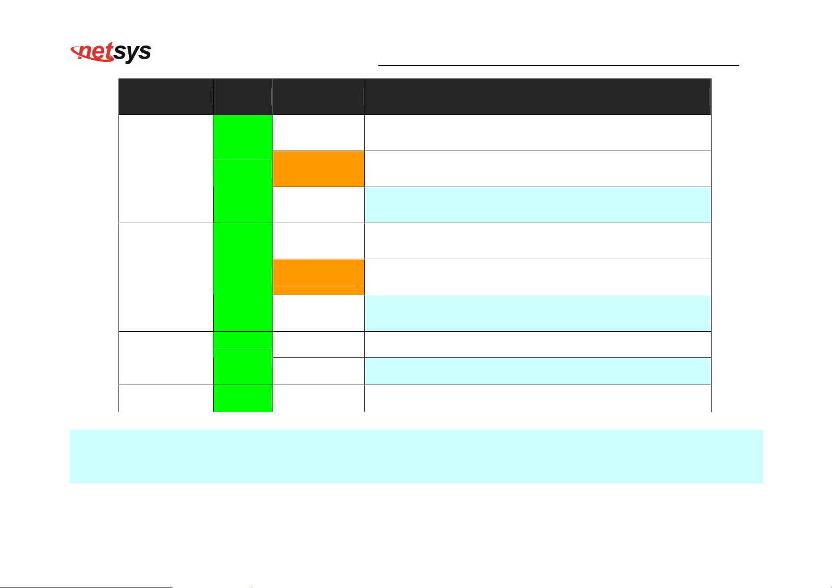
The Modem has Seven LED indicators. The following Table shows the description. (Table 3-1)
Table 3-1 LED Indicators Description and Operation
LED Color Status Descriptions
On(Steady) Lights to indicate that the VDSL2 modem had power
PWR
Green
(Power LED)
Off The device is not ready or has malfunctioned.
14
Page 16
NV-700L VDSL2 Single Master Modem USER’S MANUAL Ver. A.2
LED Color Status Descriptions
On(Steady) The device has a good Ethernet connection.
E1 ~ E4
Green
Blinking The device is sending or receiving data.
(Ethernet LED)
Off The LAN is not connected or has malfunctioned.
On(Steady) The Internet or network connection is up.
LINK
(VDSL2 LED)
Green
Fast Blinking
1. The CO device has detected a CPE device and ready to connect.
2. The device is sending or receiving data.
Off The Internet or network connection is down.
On (Steady) The device has a good USB dongle connection.
USB Green
Off The device is not ready or has malfunctioned.
CO Green On (Steady) The device has a good Master connection.
Note:
It is normal for the connection between two Modems to take up to 3 minutes, due to NV-700L/NV-720R to establish a link mechanism
in auto-negotiation, with detects and calculates CO and CPE both PBO and PSD level, noise levels and other arguments for getting
a better connection.
15
Page 17
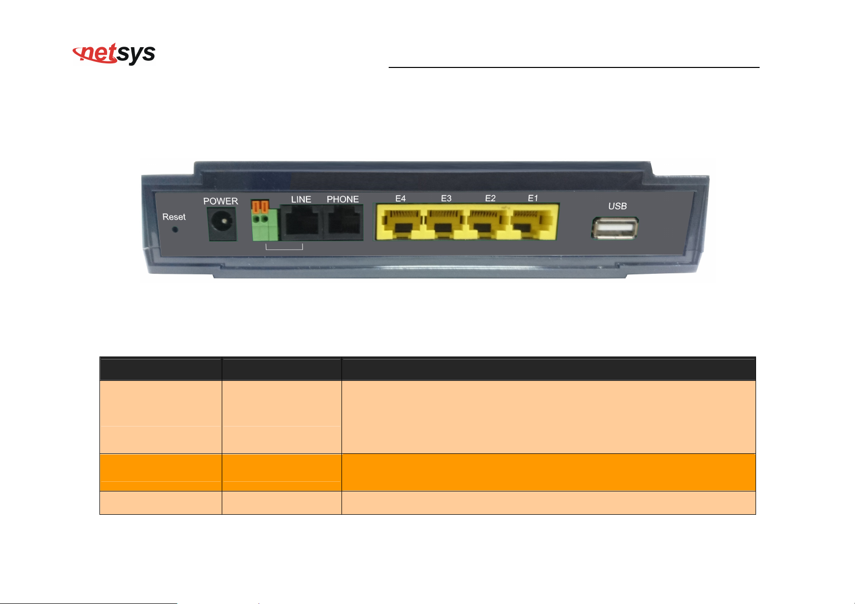
3.3 Rear Panel
The following figure shows the rear panel. (Figure 3.2)
NV-700L VDSL2 Single Master Modem USER’S MANUAL Ver. A.2
Figure 3.3 Rear Panel
And the table shows the description. (Table 3-2)
Table 3-2 Description of the modem rear connectors
Type Connector Description
The reset buttons allows users to reboot the VDSL2 or load the default
settings.
Reset Tact switch Button
Press and hold for 1-5 seconds: Reboot the VDSL2 Modem
Press over 5 seconds: Load the default settings
External switching Power Adapter: Input: AC 85~240Volts/50~60Hz.
Power DC Jack
Output: DC 12V/1A.
Line RJ-11 For connecting to a VDSL2 device.
16
Page 18
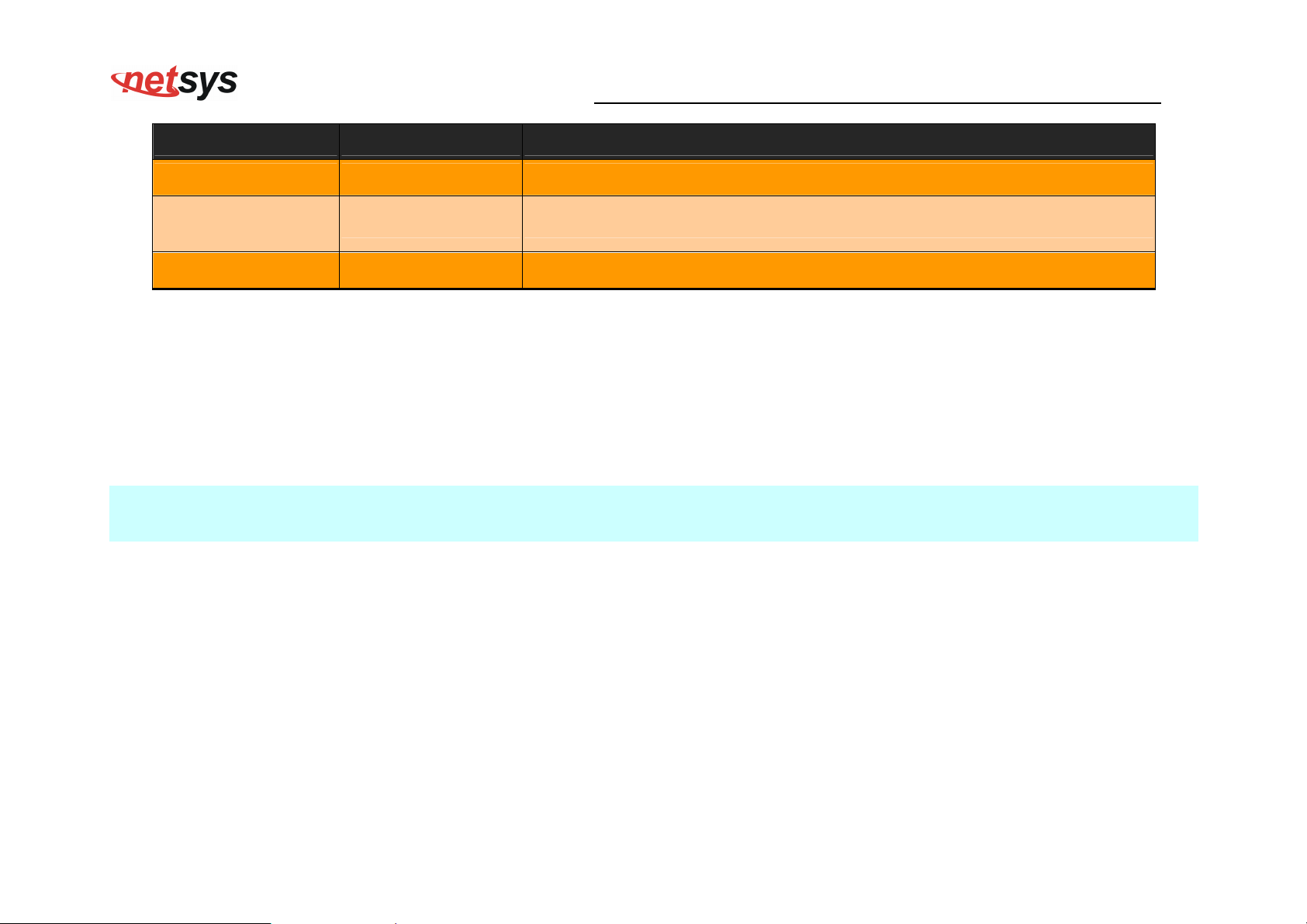
Type Connector Description
phone RJ-11 For connecting to the POTS equipment or ISDN.
NV-700L VDSL2 Single Master Modem USER’S MANUAL Ver. A.2
Ethernet
(E1-E4)
USB USB2.0 Type A For connecting to the USB dongle.
RJ-45 For connecting to an Ethernet equipped device.
Before user installed power and device, please read and follow these essentials:
Use separate paths to route wiring for power and devices. If power wiring and device wiring paths must cross, make sure the
wires are perpendicular at the intersection point.
Note:
Do not run signal or communications wiring and power wiring through the same wire conduit. To avoid interference, wires with
different signal characteristics should be routed separately.
You can use the type of signal transmitted through a wire to determine which wires should be kept separate. The rule of thumb
is that wiring sharing similar electrical characteristics can be bundled together.
You should separate input wiring from output wiring.
We recommend that you mark all equipment in the wiring system.
17
Page 19

NV-700L VDSL2 Single Master Modem USER’S MANUAL Ver. A.2
Chapter 4.
The NV-700L provides a built-in HTML based management interface that allows configuration of the NV-700L via
Internet Browser. Best viewed using Chrome or Firefox browsers.
In order to use the web browser to configure the device, you may need to allow:
Launch your web browser and input the IP address 192.168.16.249 (NV-700L) in the Web page.
Following section user can find default username and password.
Configure the NV-700L Via Web Browser
• Web browser pop-up windows from your device. Web pop-up blocking is enabled by default in windows XP
SP2 or above.
• Java Scripts. (Enabled by default)
• Java permissions. (Enabled by default)
18
Page 20
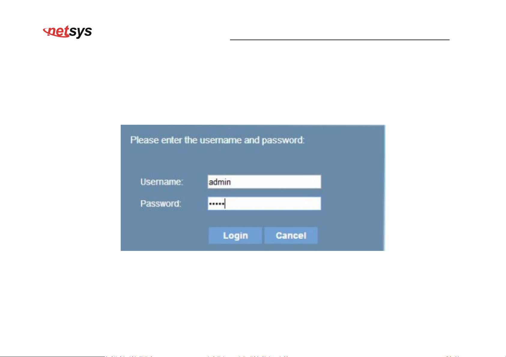
4.1 BASIC Setup
Login webpage
The IP address is 192.168.16.249 , username and password are admin.
NV-700L VDSL2 Single Master Modem USER’S MANUAL Ver. A.2
Figure 4.1 Login Password
19
Page 21
NV-700L VDSL2 Single Master Modem USER’S MANUAL Ver. A.2
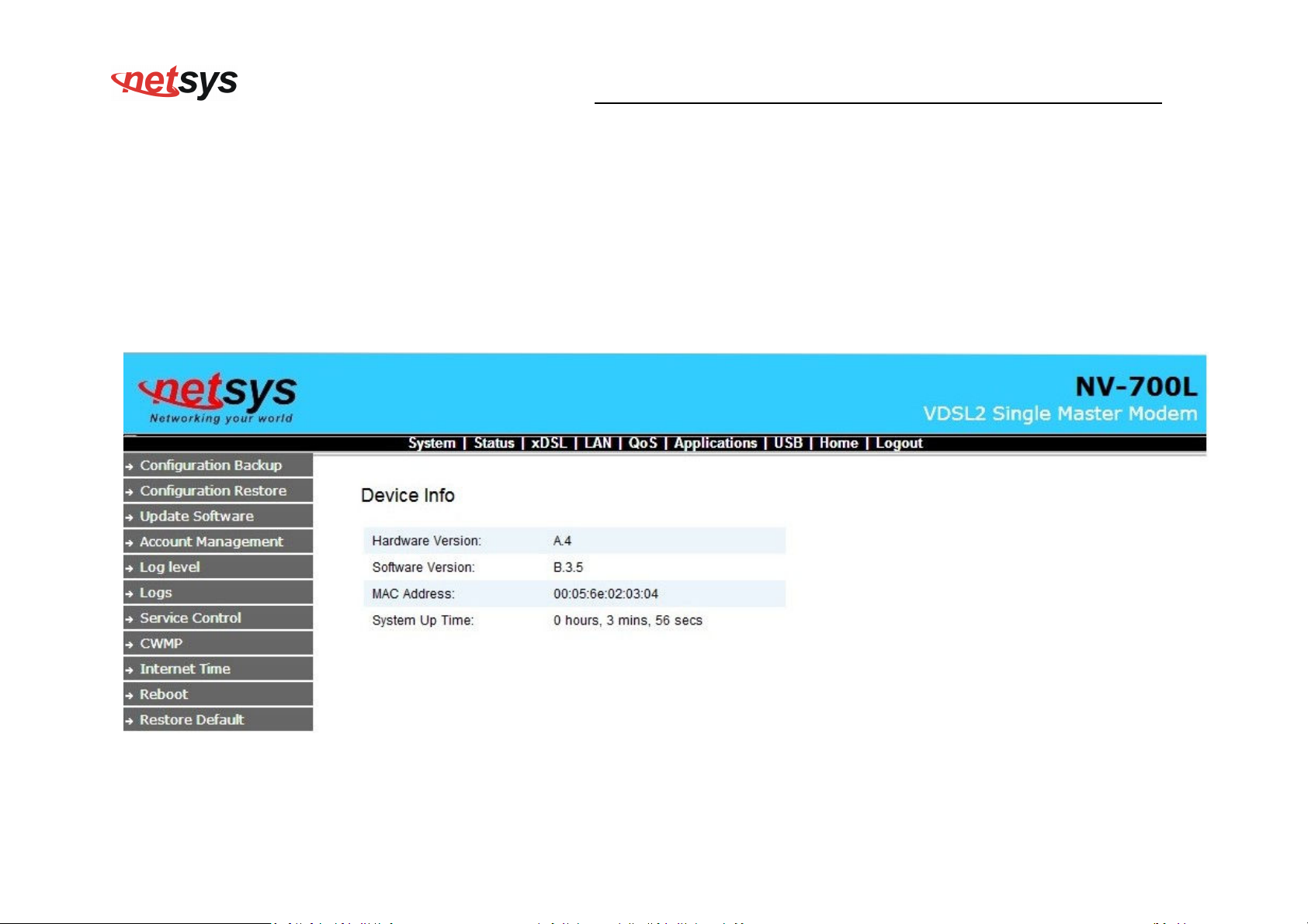
Display status
The status page displays some information. When the device is running.
For example:
Device Information:
20
Page 22
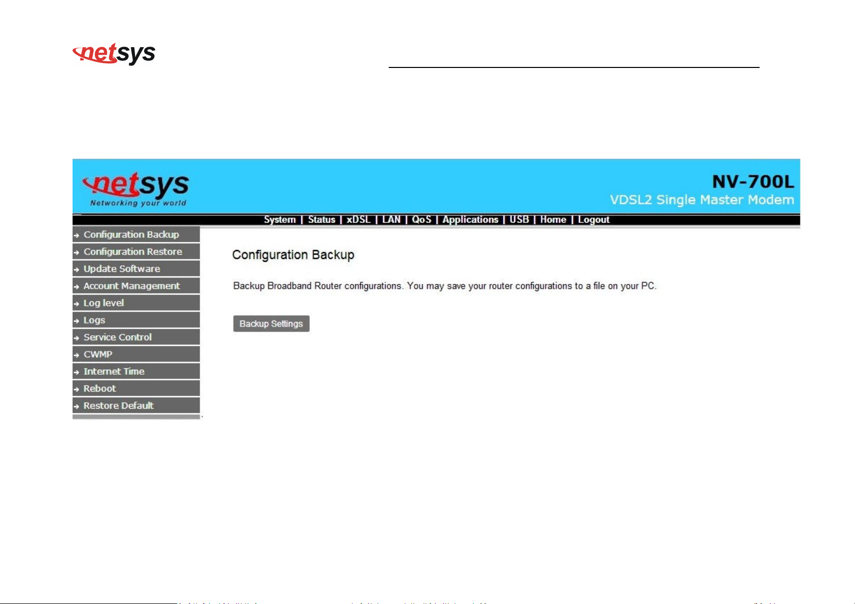
4.2 System Setup
System–> Configuration Backup
NV-700L VDSL2 Single Master Modem USER’S MANUAL Ver. A.2
21
Page 23
NV-700L VDSL2 Single Master Modem USER’S MANUAL Ver. A.2
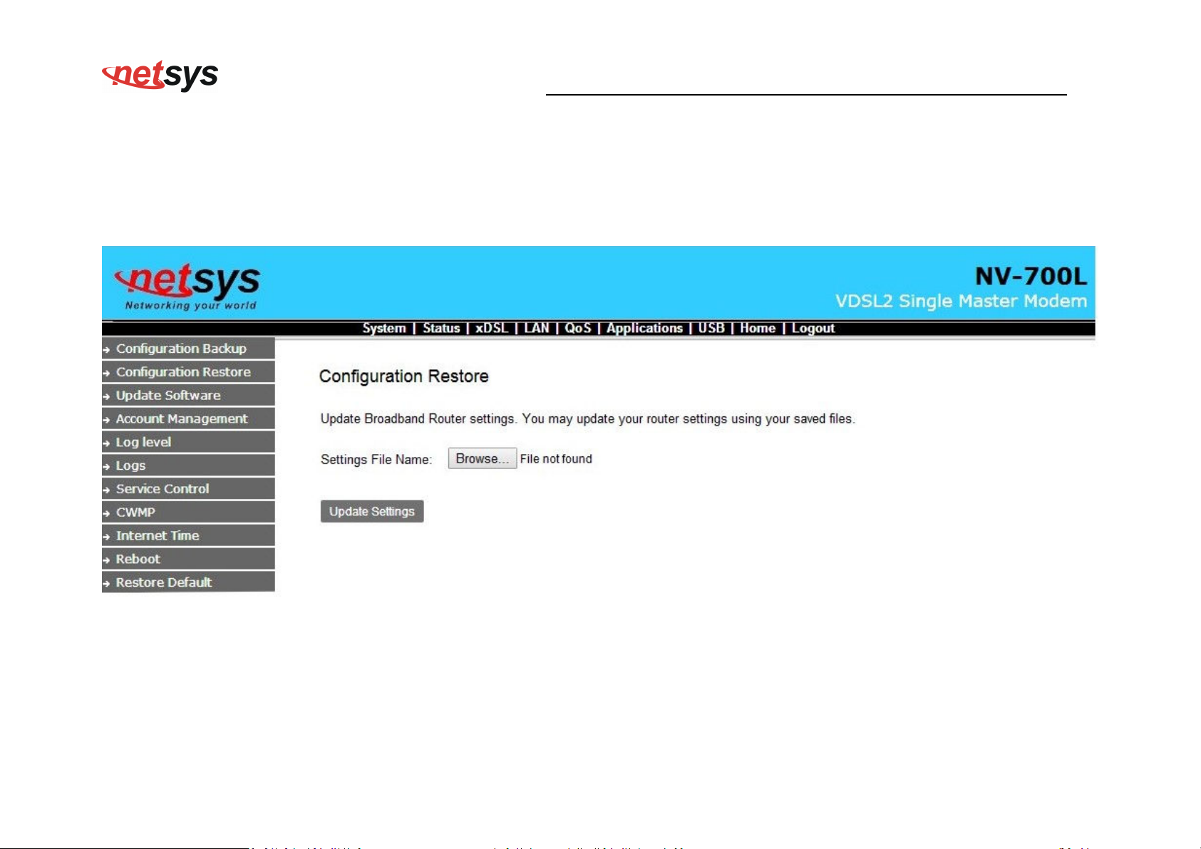
System-> Configuration Restore
Select “System” ->”Restore Default”
If Click “Restore Default Settings”, the device will reboot in 10 seconds.
22
Page 24
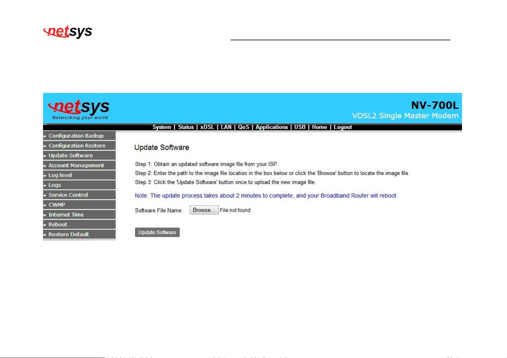
System->Update Software
Select “System”->”update software”
NV-700L VDSL2 Single Master Modem USER’S MANUAL Ver. A.2
Choose the newest Firmware file and do upgrading.
23
Page 25
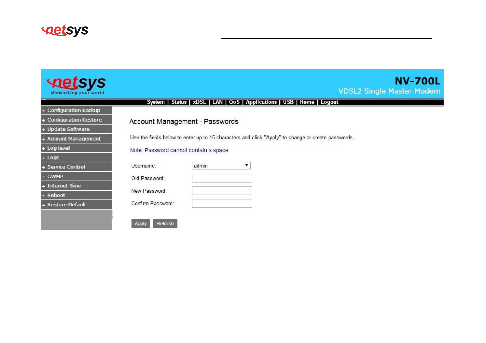
system->Account Management
NV-700L VDSL2 Single Master Modem USER’S MANUAL Ver. A.2
24
Page 26
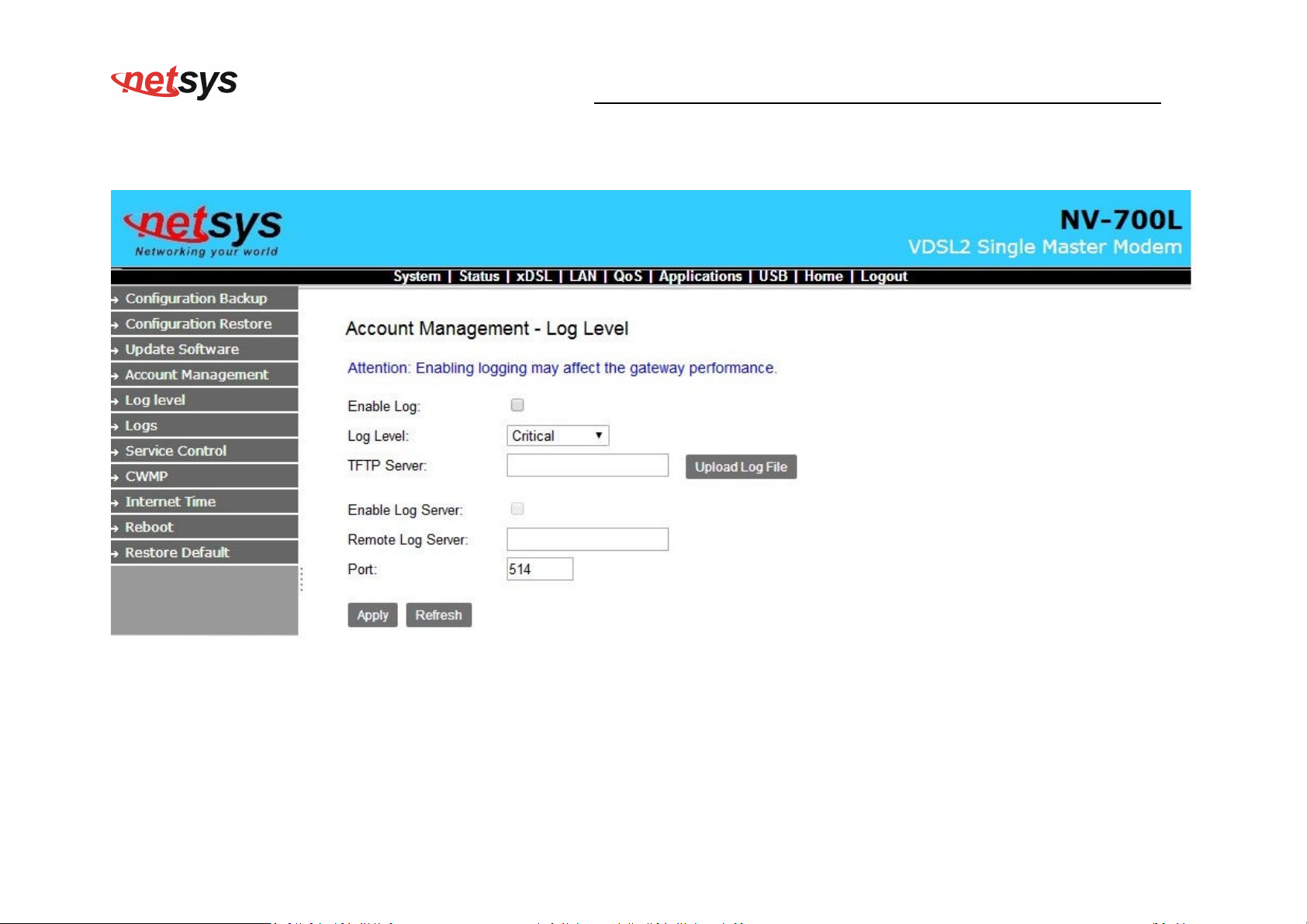
NV-700L VDSL2 Single Master Modem USER’S MANUAL Ver. A.2
system->Account Management - Log Level
25
Page 27
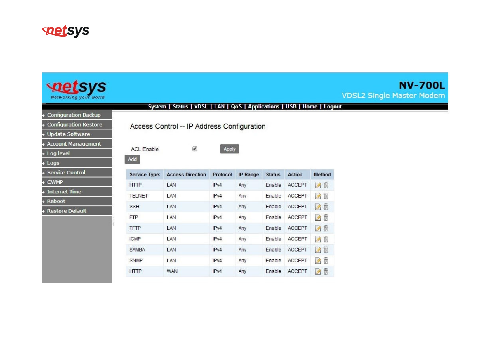
System->Service control
NV-700L VDSL2 Single Master Modem USER’S MANUAL Ver. A.2
26
Page 28
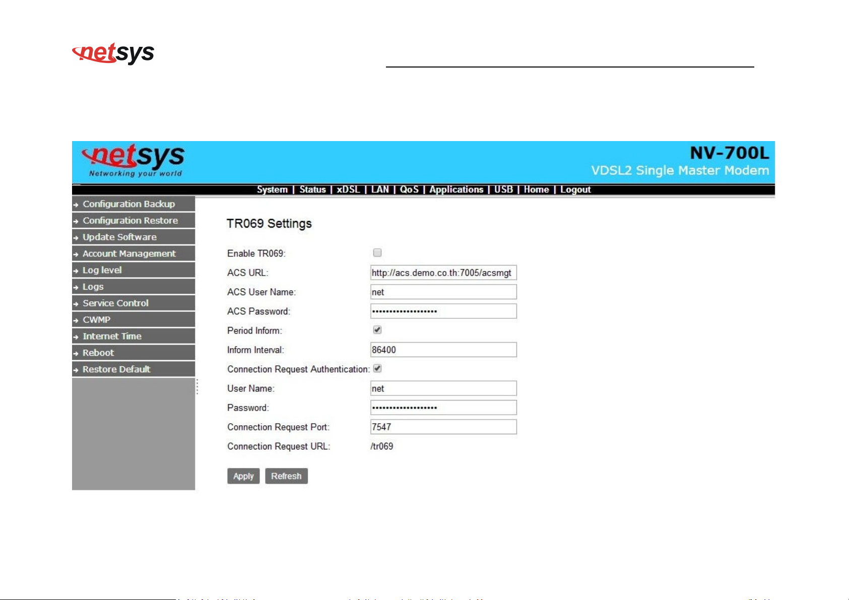
System->CWNP->TR-069 Settings
NV-700L VDSL2 Single Master Modem USER’S MANUAL Ver. A.2
In System/CWMP page setup ACS URL/Username/Password TR069 and basic information.
27
Page 29
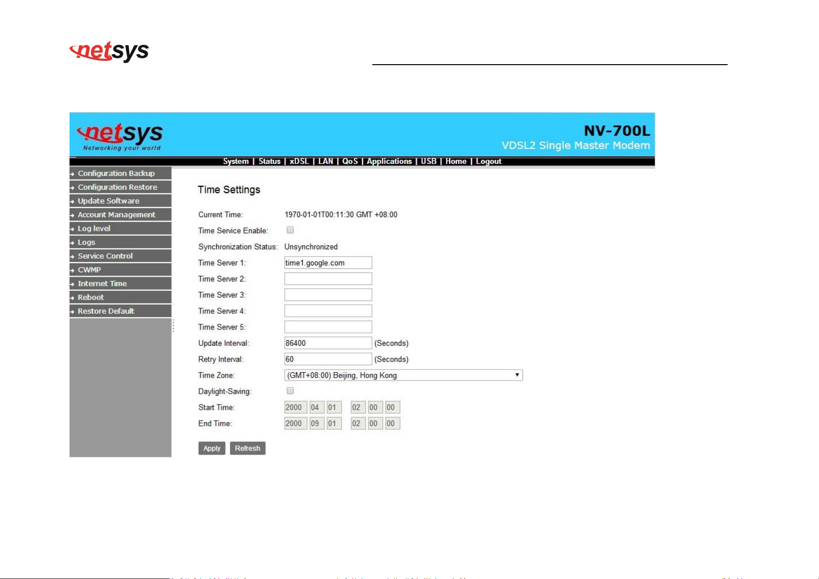
System->Internet Time
NV-700L VDSL2 Single Master Modem USER’S MANUAL Ver. A.2
28
Page 30
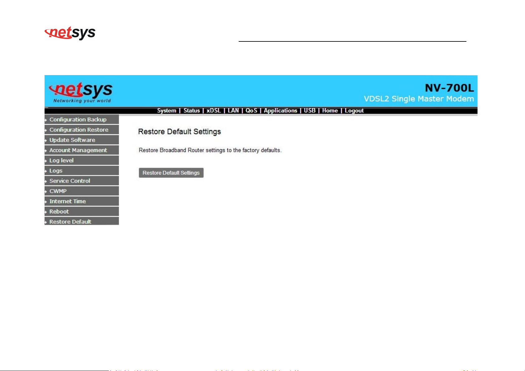
System->Restore Default Setting
NV-700L VDSL2 Single Master Modem USER’S MANUAL Ver. A.2
29
Page 31
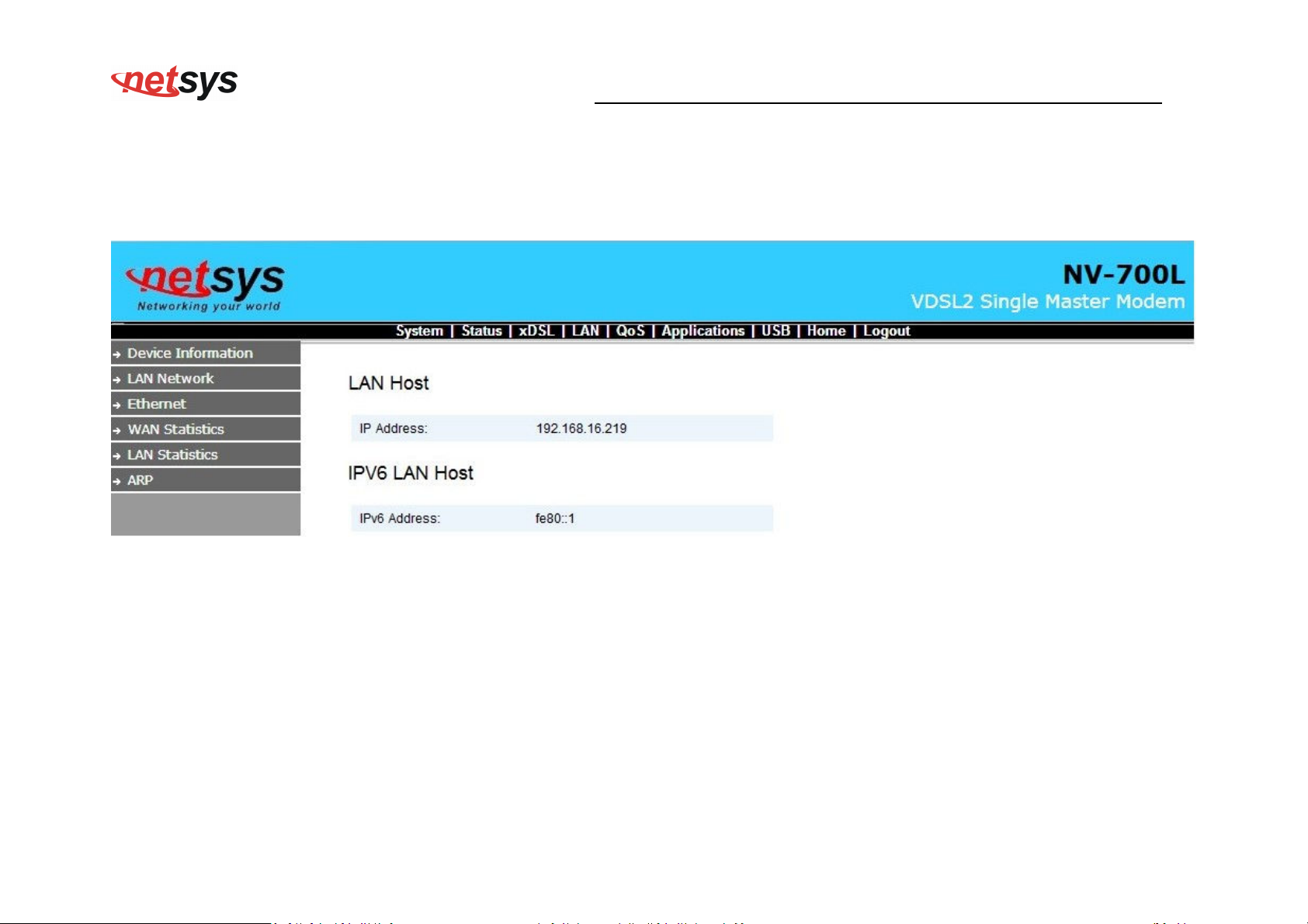
NV-700L VDSL2 Single Master Modem USER’S MANUAL Ver. A.2
4.3 Status Setup
Status ->LAN Network
30
Page 32
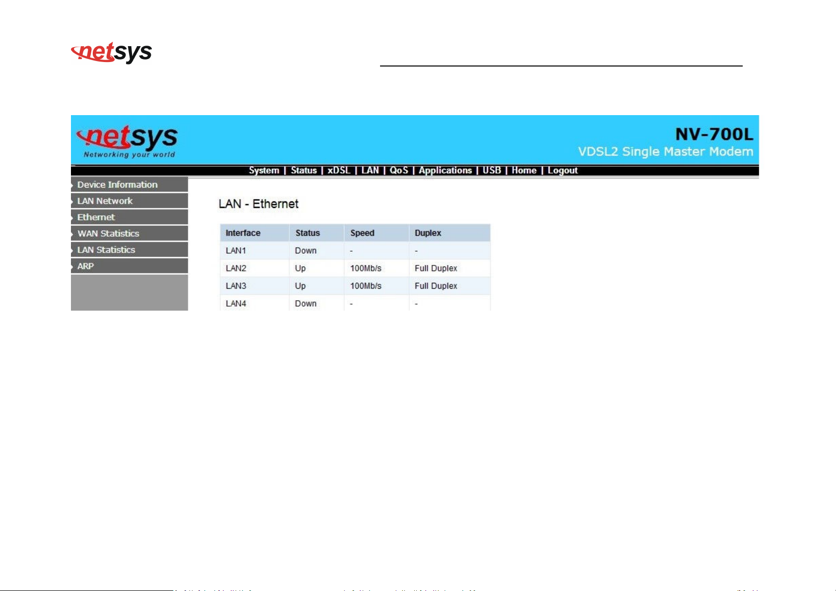
Status->LAN-> Ethernet
NV-700L VDSL2 Single Master Modem USER’S MANUAL Ver. A.2
31
Page 33
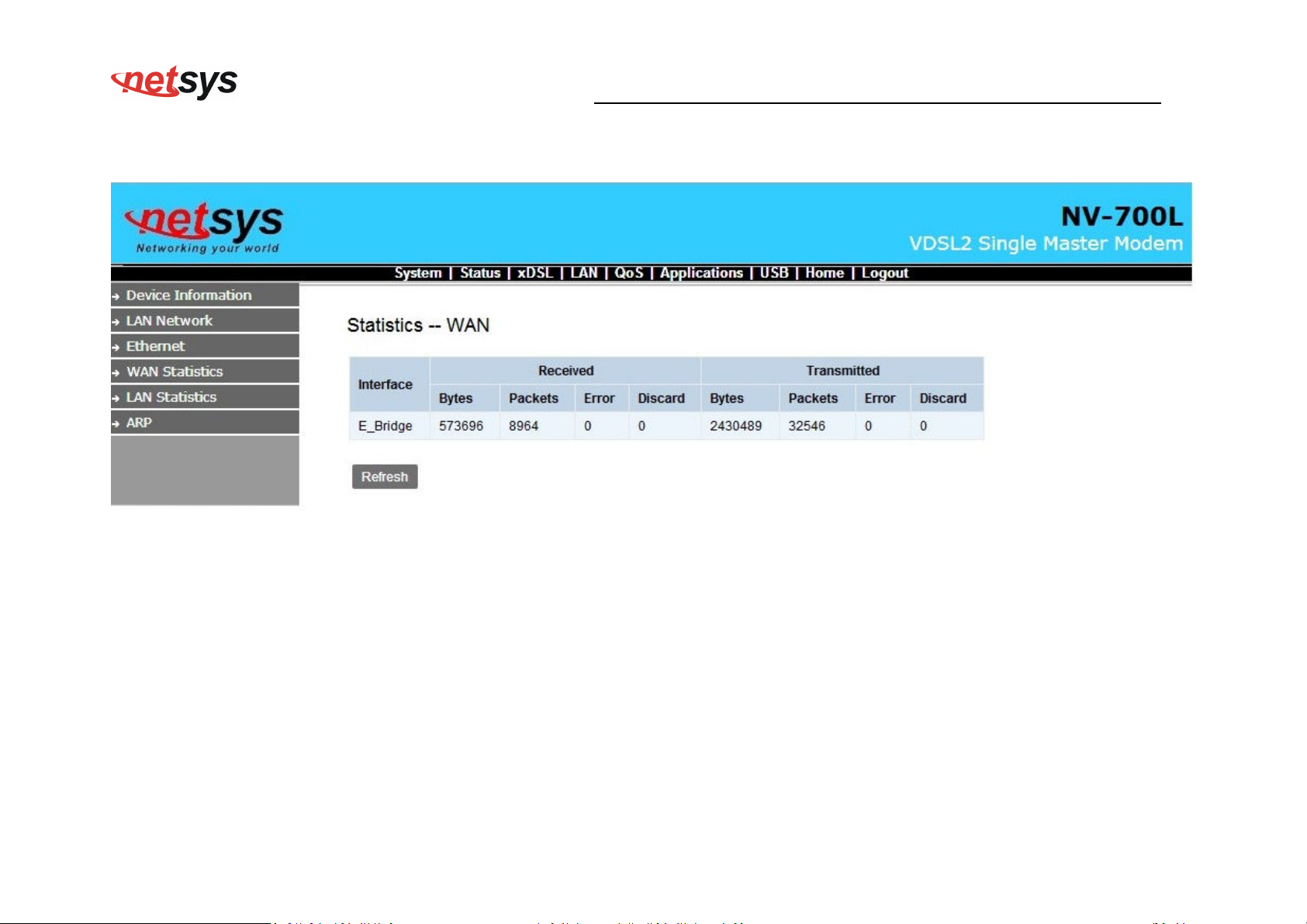
Status->WAN Statistics
NV-700L VDSL2 Single Master Modem USER’S MANUAL Ver. A.2
32
Page 34
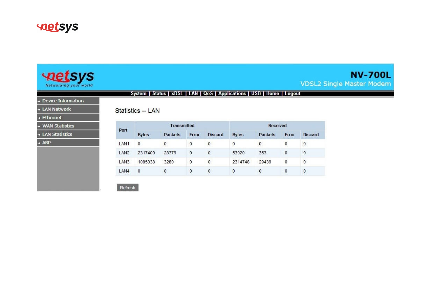
Status->LAN Statistics
NV-700L VDSL2 Single Master Modem USER’S MANUAL Ver. A.2
33
Page 35
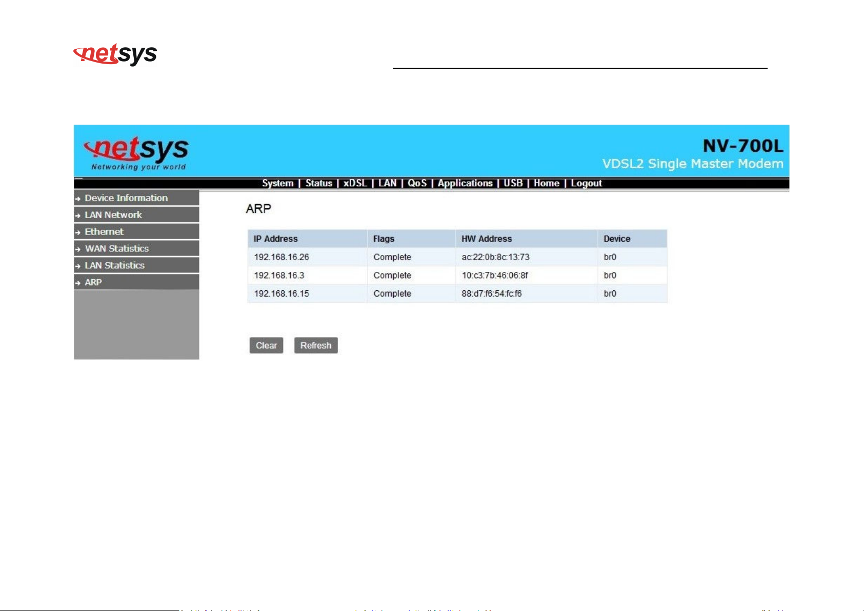
Status->ARP
NV-700L VDSL2 Single Master Modem USER’S MANUAL Ver. A.2
34
Page 36
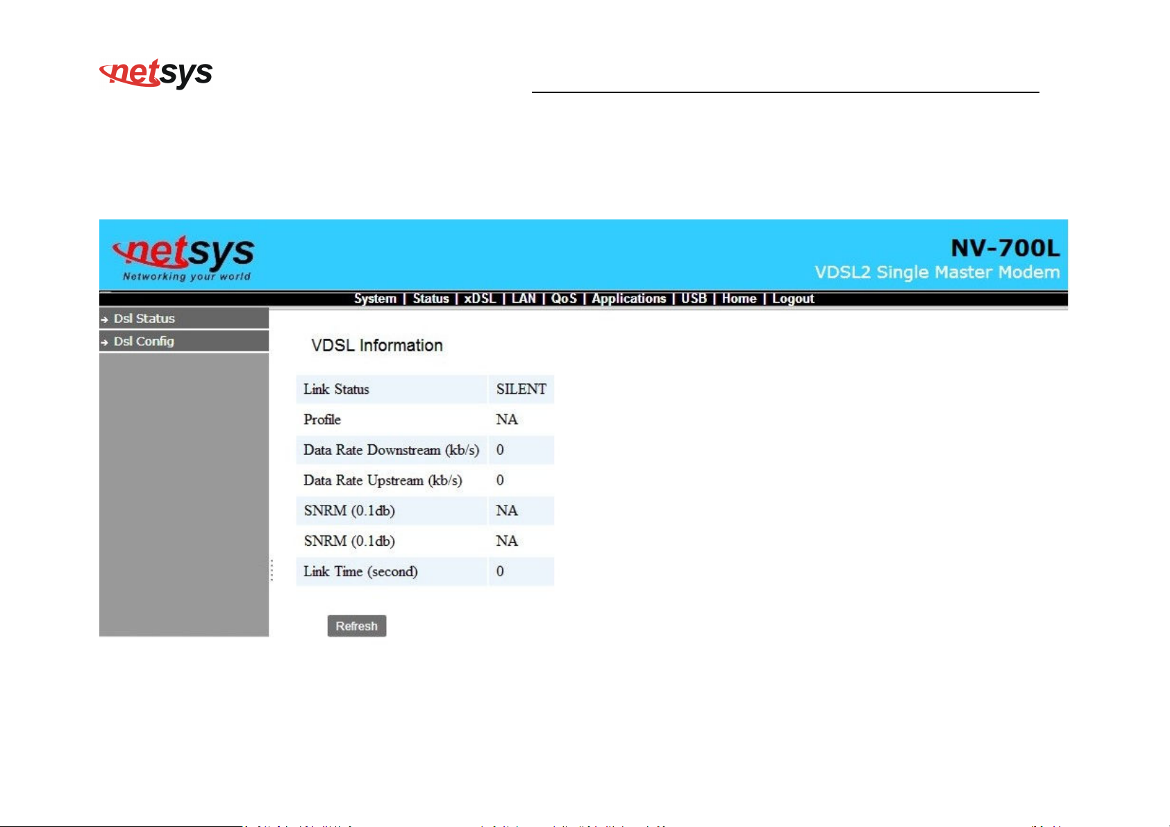
NV-700L VDSL2 Single Master Modem USER’S MANUAL Ver. A.2
4.4 Xdsl SETUP
Xdsl ->DSL STATUS
35
Page 37
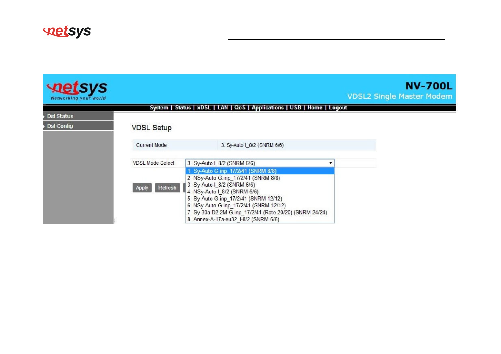
Xdsl-DSL Config
NV-700L VDSL2 Single Master Modem USER’S MANUAL Ver. A.2
36
Page 38
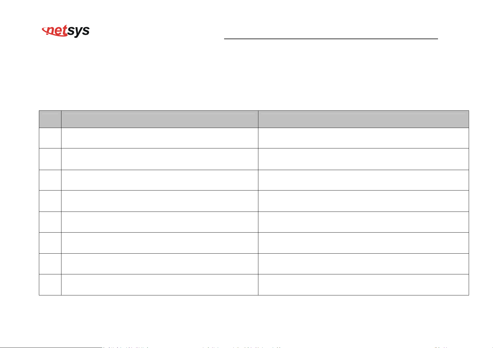
VDSL Config Overview
The page to configure VDSL Mode.
Support table:
NO
.
Config. Note
NV-700L VDSL2 Single Master Modem USER’S MANUAL Ver. A.2
1 Sy-Auto G.INP_17/2/41 (SNRM 8/8)
2 NSy-Auto G.INP_17/2/41 (SNRM 8/8)
3 Sy-Auto I_8/2 (SNRM 6/6)
4 NSy-Auto I_8/2 (SNRM 6/6)
5 Sy-Auto G.INP_17/2/41 (SNRM 12/12)
6 NSy-Auto G.INP_17/2/41 (SNRM 12/12)
7 Sy-30a-D2.2M G.INP_17/2/41 (Rate 20/20) (SNRM 24/24)
8 Annex-A-17a-eu32_I-8/2 (SNRM 6/6)
Symmetric Auto, enable G. INP, enable re-transmition,
SNRM=8
non symmetric Auto, enable G.INP, enable re-transmition,
SNRM=8
Symmetric Auto, Max. Interleave=8, Min.Inp=2,
SNRM=6 (Default)
Non symmetric Auto, Max. Interleave=8, Min.Inp=2,
SNRM=6
Symmetric Auto, enable G.INP, enable re-transmition,
SNRM=12
non symmetric Auto, enable G.INP, enable re-transmition,
SNRM=12
Symmetric 30a, disable 0~2.2MHz, enable G.INP, enable
re-transmition, Max.Line rate=20Mbps, SNRM=24
17A Annex A Eu32, Max. Interleave=8, Min. Inp=2,
SNRM=6
37
Page 39
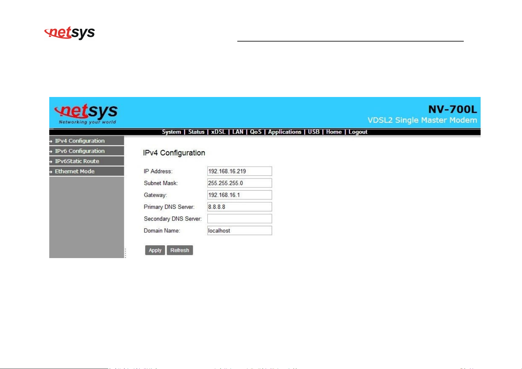
4.5 LAN Setup
LAN >IPV4 Configuration
NV-700L VDSL2 Single Master Modem USER’S MANUAL Ver. A.2
38
Page 40
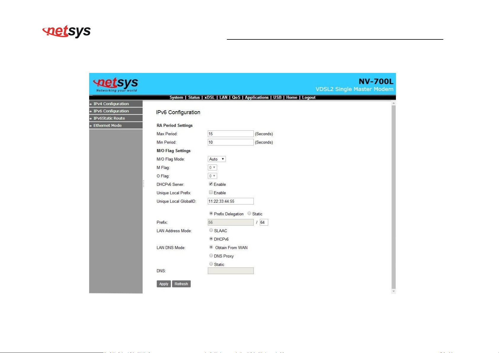
LAN->IPv6 Configuration:
NV-700L VDSL2 Single Master Modem USER’S MANUAL Ver. A.2
39
Page 41
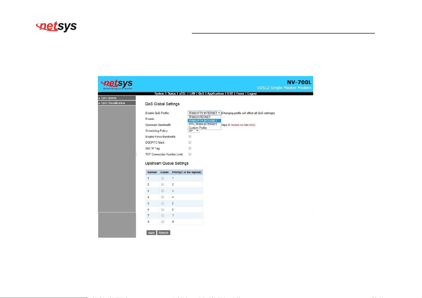
4.6 Qos SETUP
Qos ->Qos Queue
NV-700L VDSL2 Single Master Modem USER’S MANUAL Ver. A.2
40
Page 42
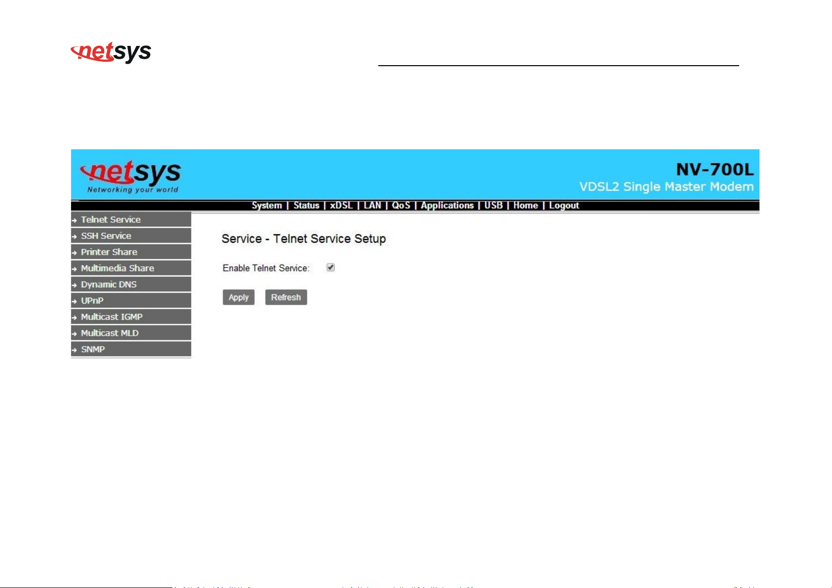
4.7 Application Setup
Application->Telnet Service Setup
NV-700L VDSL2 Single Master Modem USER’S MANUAL Ver. A.2
41
Page 43
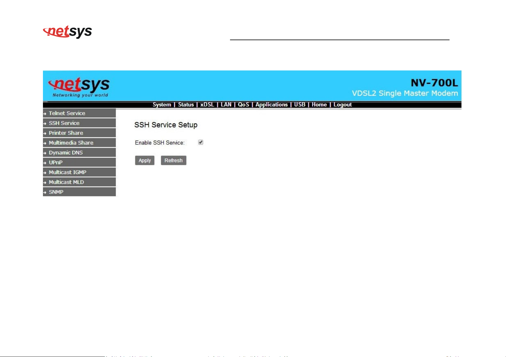
Application-> SSH Service
NV-700L VDSL2 Single Master Modem USER’S MANUAL Ver. A.2
42
Page 44
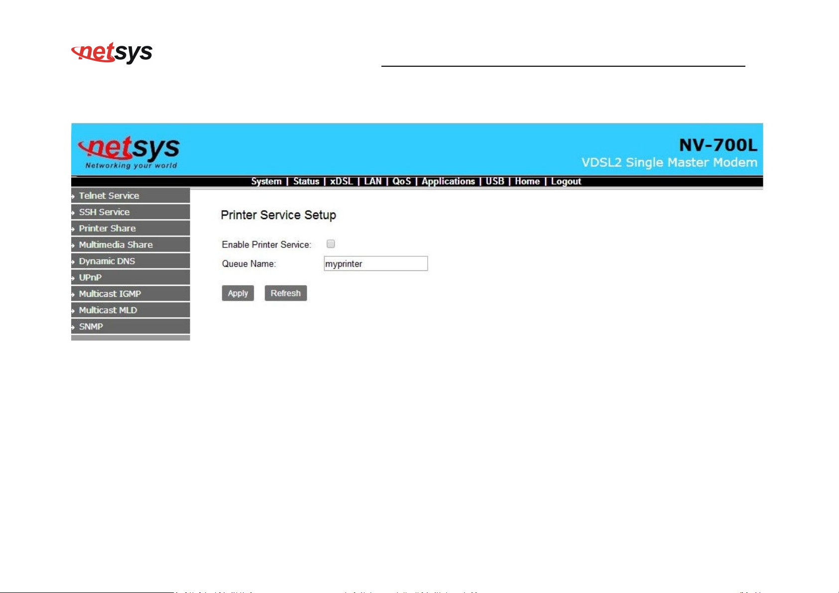
Application->Printer Share
NV-700L VDSL2 Single Master Modem USER’S MANUAL Ver. A.2
43
Page 45
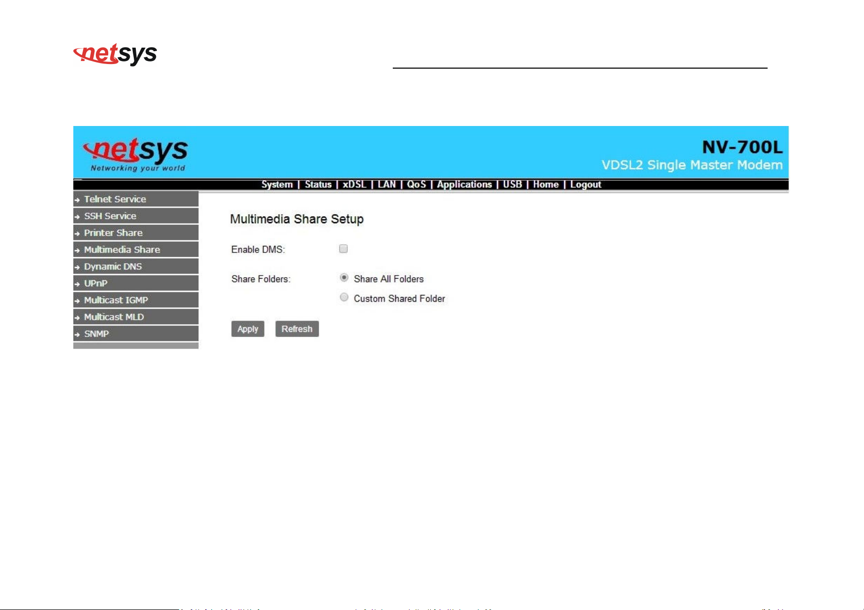
Application->Multimedia Share
NV-700L VDSL2 Single Master Modem USER’S MANUAL Ver. A.2
44
Page 46
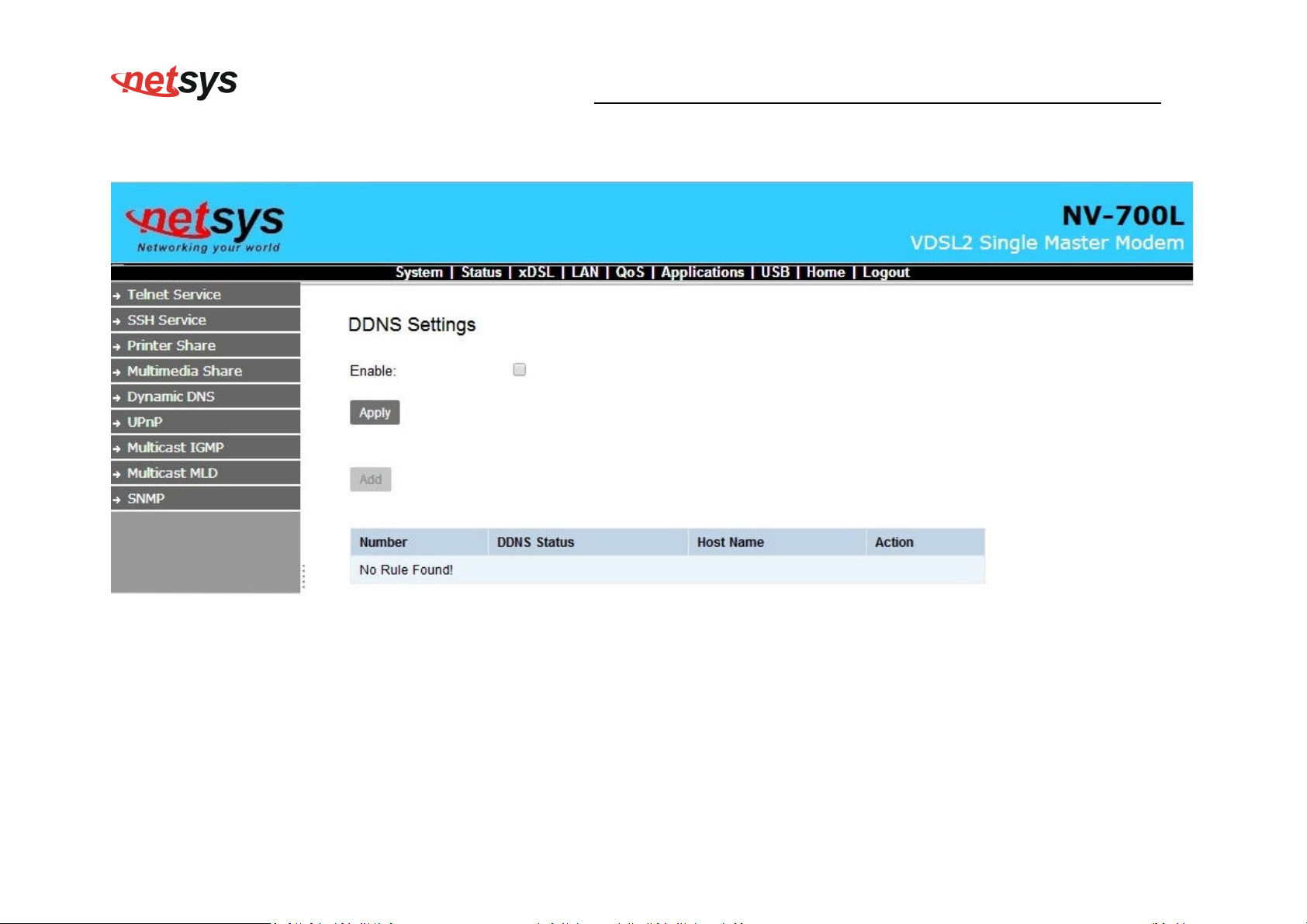
Application->Dynamic DNS
NV-700L VDSL2 Single Master Modem USER’S MANUAL Ver. A.2
45
Page 47
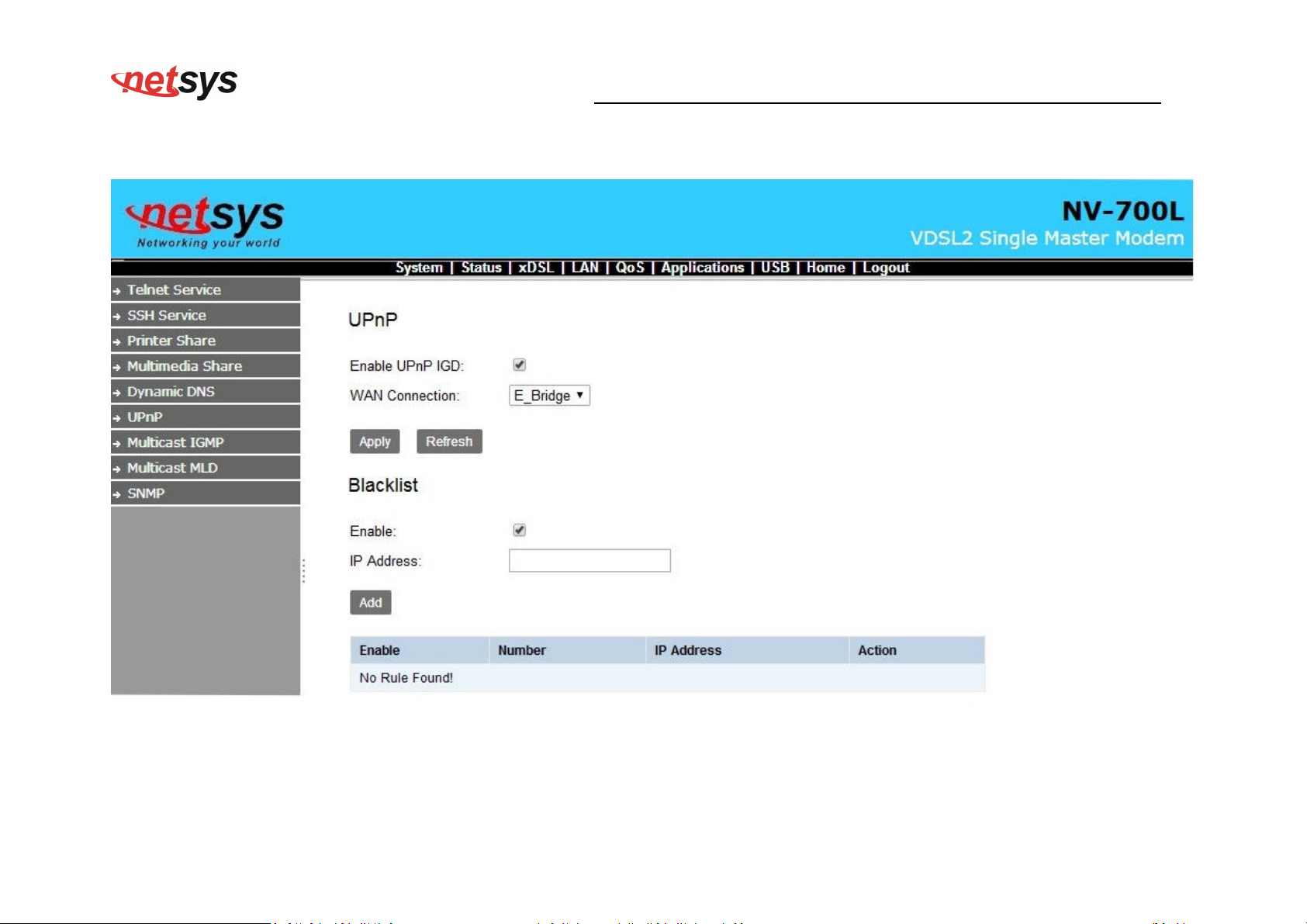
Application->UPnP
NV-700L VDSL2 Single Master Modem USER’S MANUAL Ver. A.2
46
Page 48
NV-700L VDSL2 Single Master Modem USER’S MANUAL Ver. A.2
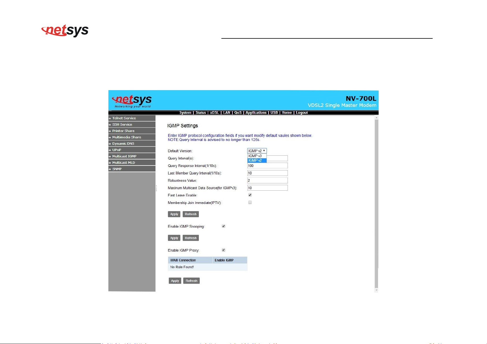
Application->multicast IGMP setting
According to the setting, if you want to test IGMP function, you only need to enable IGMP function basic on the
Application SETUP
47
Page 49
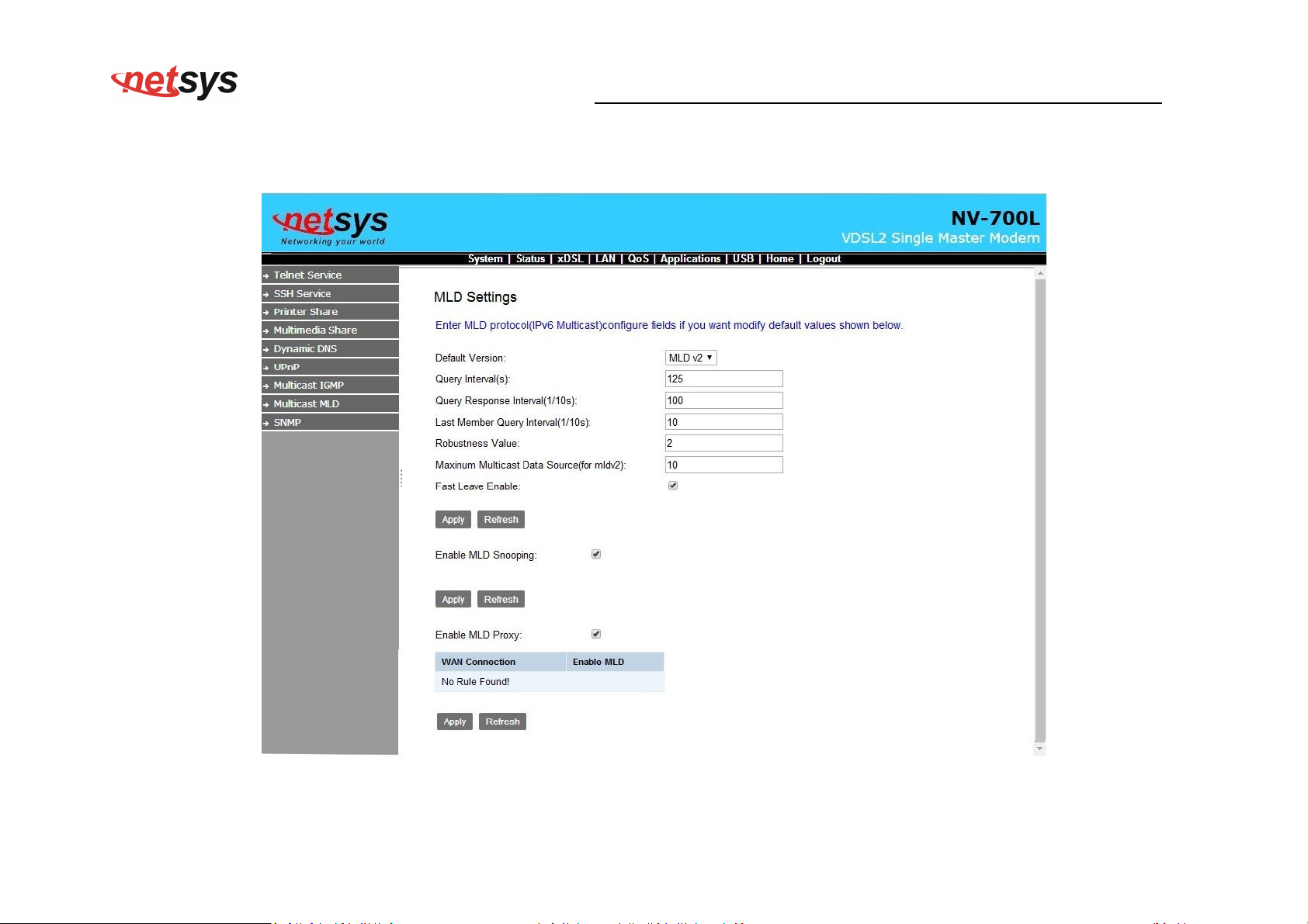
Application->Multicast MLD
NV-700L VDSL2 Single Master Modem USER’S MANUAL Ver. A.2
48
Page 50
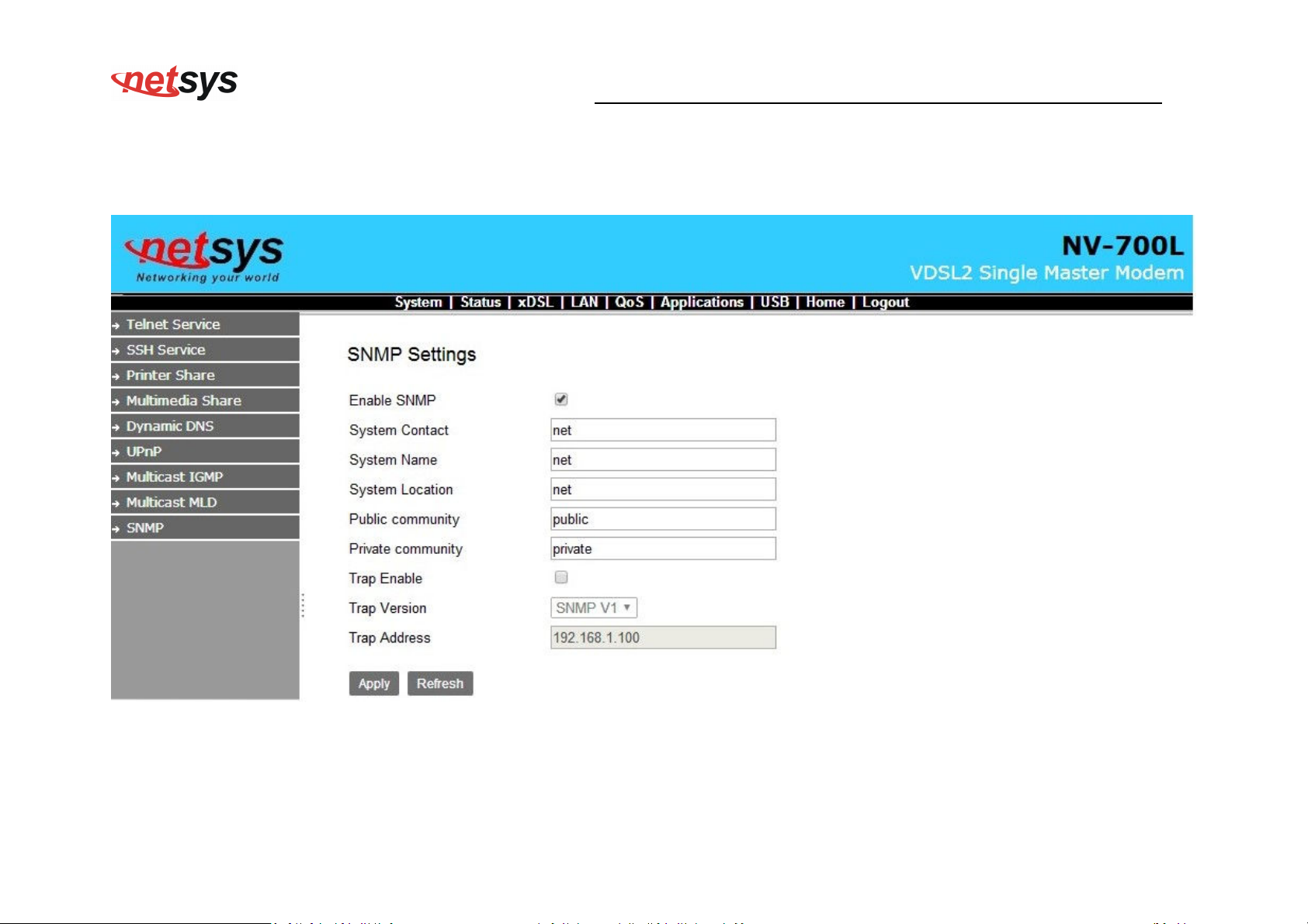
APPLICATION->SNMP
NV-700L VDSL2 Single Master Modem USER’S MANUAL Ver. A.2
Below is picture for how to enable SNMP function, device support SNMP V1/V2
49
Page 51
NV-700L VDSL2 Single Master Modem USER’S MANUAL Ver. A.2
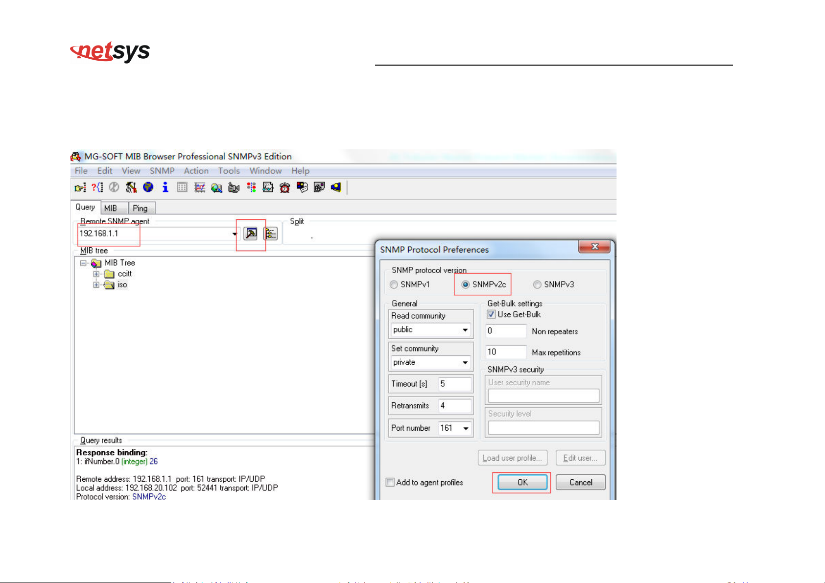
Download “MG-SOFT MIB Browser”. below is picture for how to use the software.
Connect Remote SNMP agant.
50
Page 52
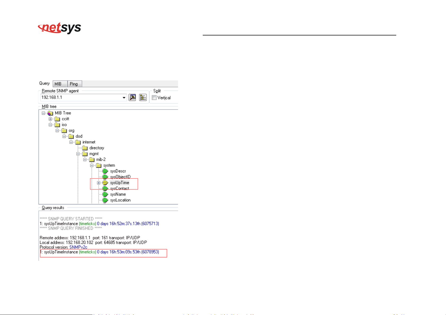
Select OID:1.3.6.1.2.1.1.3
NV-700L VDSL2 Single Master Modem USER’S MANUAL Ver. A.2
System Up Time
51
Page 53
NV-700L VDSL2 Single Master Modem USER’S MANUAL Ver. A.2
4.8 USB setup
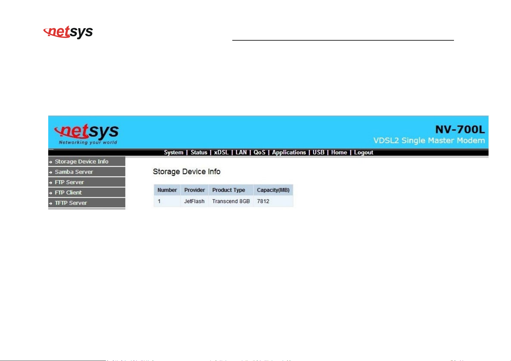
USB-Storage Device Info
Insert a U disk into the USB interface, then login 192.168.16.249,select “USB”->” Storage Device Info”. Confirm the
system has mounted the U disk.
52
Page 54
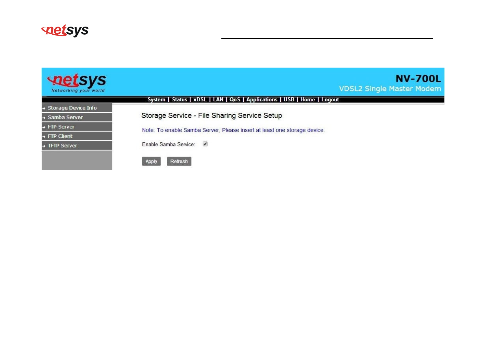
USB->Samba Service
NV-700L VDSL2 Single Master Modem USER’S MANUAL Ver. A.2
53
Page 55
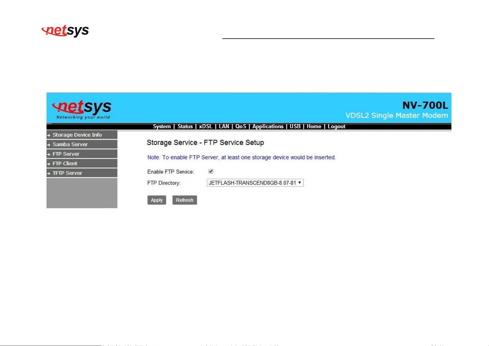
USB-> FTP Server
Below is picture for how to enable FTP Server function.
NV-700L VDSL2 Single Master Modem USER’S MANUAL Ver. A.2
54
Page 56
NV-700L VDSL2 Single Master Modem USER’S MANUAL Ver. A.2
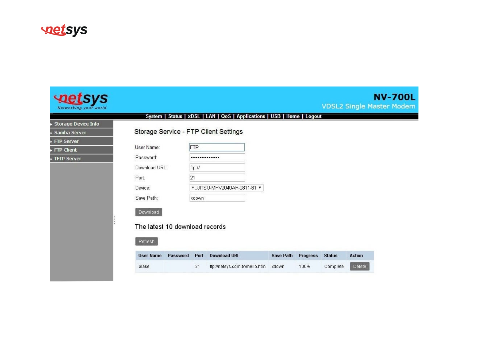
USB-> FTP Client
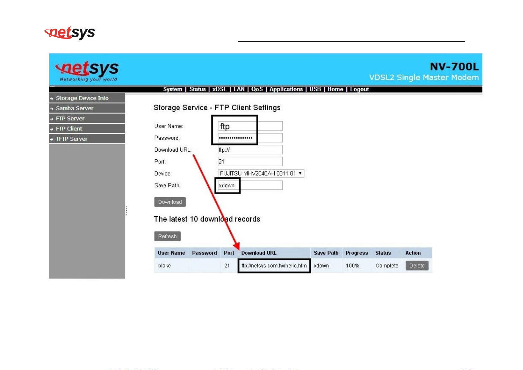
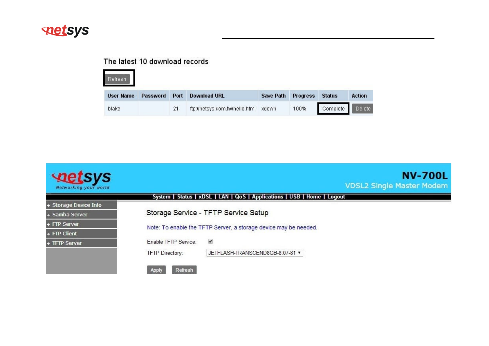
Below is picture for how to enable FTP Client function. Input FTP Client Settings, then chick “Download”
55
Page 57
NV-700L VDSL2 Single Master Modem USER’S MANUAL Ver. A.2
56
Page 58
NV-700L VDSL2 Single Master Modem USER’S MANUAL Ver. A.2
Click “Refresh”, Make sure the status is complete.
USB-> TFTP Server
Below is picture for how to enable TFTP Server function.
57
Page 59
NV-700L VDSL2 Single Master Modem USER’S MANUAL Ver. A.2
Appendix A: Cable Requirements
A.1 Ethernet Cable
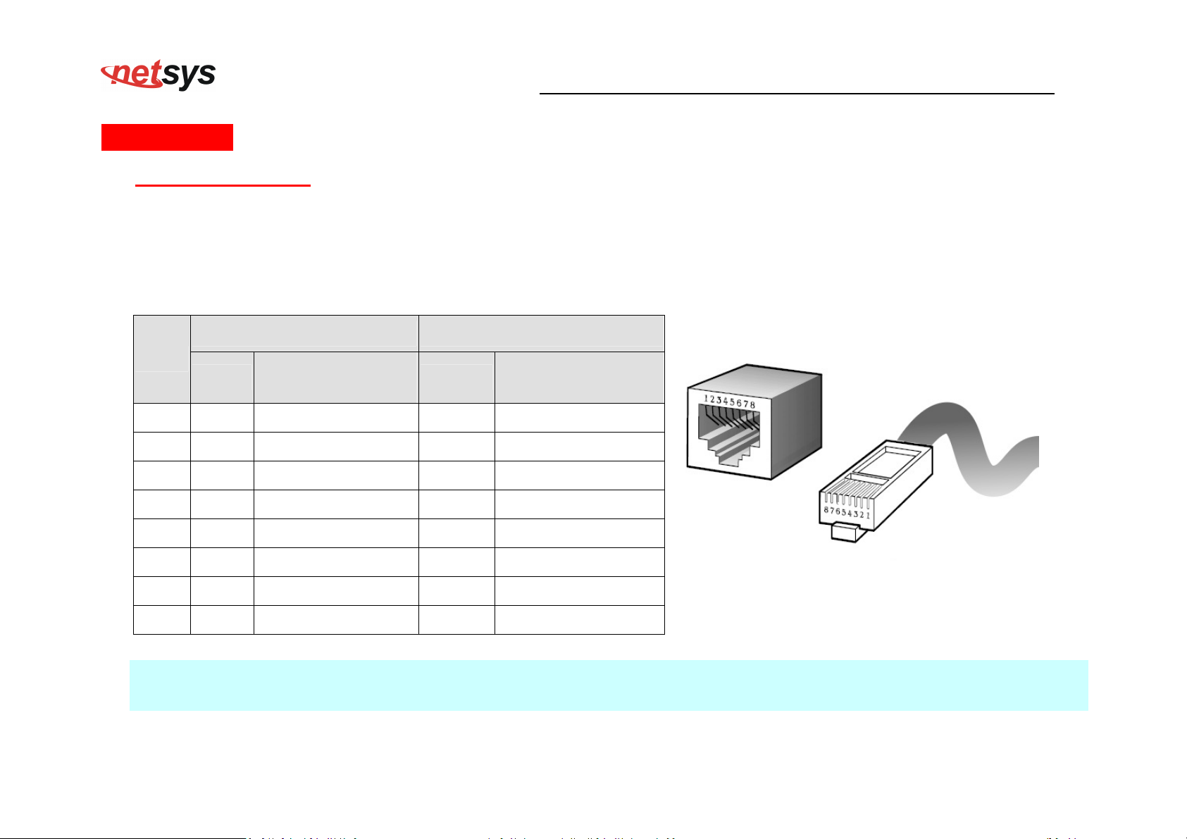
A CAT 3~7 UTP (unshielded twisted pair) cable is typically used to connect the Ethernet device to the Modem. A 10Base-T
cable often consists of four pairs of wires, two of which are used for transmission. The connector at the end of the 10Base-T
cable is referred to as an RJ-45 connector and it consists of eight pins. The Ethernet standard uses pins 1, 2, 3 and 6 for
data transmission purposes. (Table A-1)
Table A-1 RJ-45 Ethernet Connector Pin Assignments
MDI MDI-X
PIN #
Signal
1 TX+ Transmit Data + RX+ Receive Data +
2 TX- Transmit Data - RX- Receive Data -
3 RX+ Receive Data + TX+ Transmit Data +
4 -- Unused -- Unused
5 -- Unused -- Unused
6 RX- Receive Data - TX- Transmit Data -
7 -- Unused -- Unused
8 -- Unused -- Unused
Note:
Please make sure your connected cables have the same pin assignment as the table above before deploying the cables into
your network.
Media Dependant
interface
Signal
Media Dependant
interface-cross
Figure A-1 Standard RJ-45 repectacle/connector
58
Page 60
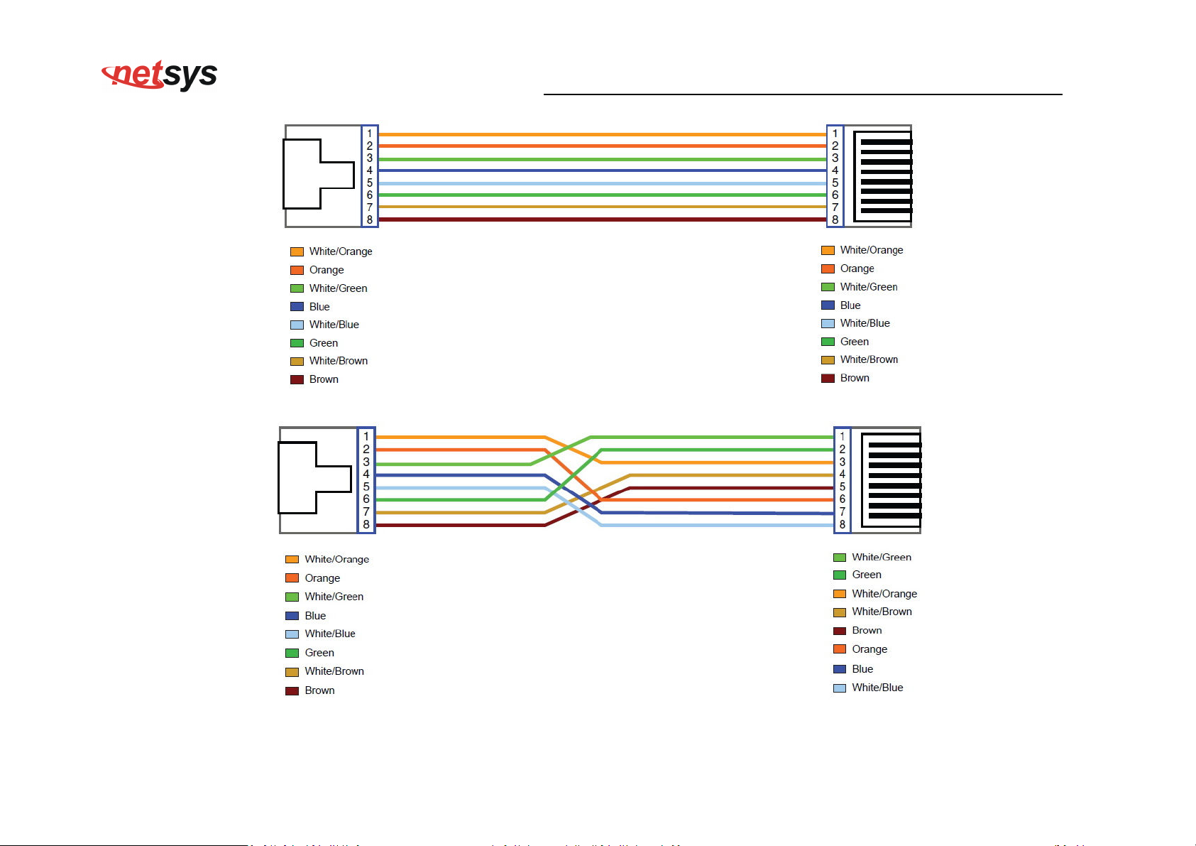
Figure A-2 Pin Assignments and Wiring for an RJ-45 Straight-Through Cable
NV-700L VDSL2 Single Master Modem USER’S MANUAL Ver. A.2
Figure A-3 Pin Assignments and Wiring for an RJ-45 Crossover Cable
59
Page 61
NV-700L VDSL2 Single Master Modem USER’S MANUAL Ver. A.2
A.2 Telephone wire
Standard telephone wire of any gauge or type-flat, twisted or quad is used to connect the Modem to the telephone network. A
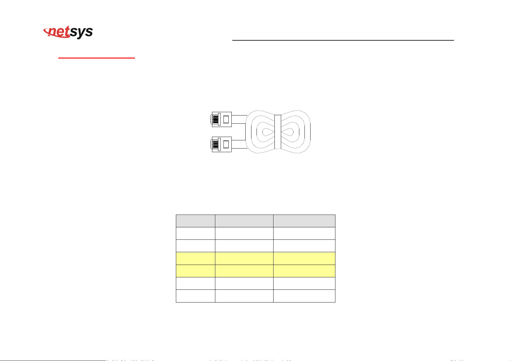
telephone cable typically consists of three pairs of wires, one of which is used for transmission. The connector at the end of
the telephone cable is called an RJ-11 connector and it consists of six pins. POTS (plain old telephone services) use pins 3
and 4 for voice transmission. A telephone cable is shown below. (Figure A-4)
A
B
Figure A-4 Telephone cable
The A and B connectors on the rear of the Modem are RJ-11 connectors. These connectors are wired identically. The RJ-11
connectors have six positions, two of which are wired. The Modem uses the center two pins. The pin out assignment for
these connectors is presented below. (Table A-2)
Table A-2 RJ-11 Pin out Assignments
Pin# MNEMONIC FUNCTION
1 NC Unused
2 NC Unused
3 TIP POTS
4 RING POTS
5 NC Unused
6 NC Unused
60
Page 62

NV-700L VDSL2 Single Master Modem USER’S MANUAL Ver. A.2
Appendix B: Product Specification
Key Features & Benefits
Adopts ARM Cortex A9 dual-core processor
Supports G.998.4 G.INP
Supports up to 100 Mbps symmetric
Support 8 bands selectable
Support USB 2.0 for connecting USB Dongle
Supports IPv4/IPv6 NTP Client
Support static routing for IPv4 and IPv6 forwarding
Mac Address based filtering
Web-based management
Support IGMP snooping v2/v3
Compliant with IEEE 802.3 & 802.3u Ethernet Standard
Support VLAN Tag pass through
Compliant with ITU-T G993.2 VDSL2 standard
Support 8 queue MFC/DSCP both type QoS
Supports HTTP/HTTPS web management
Support SSL / SSH security
Compliant with ITU-T G993.2 VDSL2 standard
Support remote management and monitor
Support configuration backup and restore
On board surge protection for Line port
61
Page 63

Support CO side bridge mode
Supports Dual Firmware Image Backup
Supports SNMP v1/v2
On board POTS/ISDN splitter
Supports TR-069
Note:
1. Features and specifications in this manual are subject to change without prior notice.
2. (*) Firmware upgradeable for future enhancement.
NV-700L VDSL2 Single Master Modem USER’S MANUAL Ver. A.2
62
Page 64
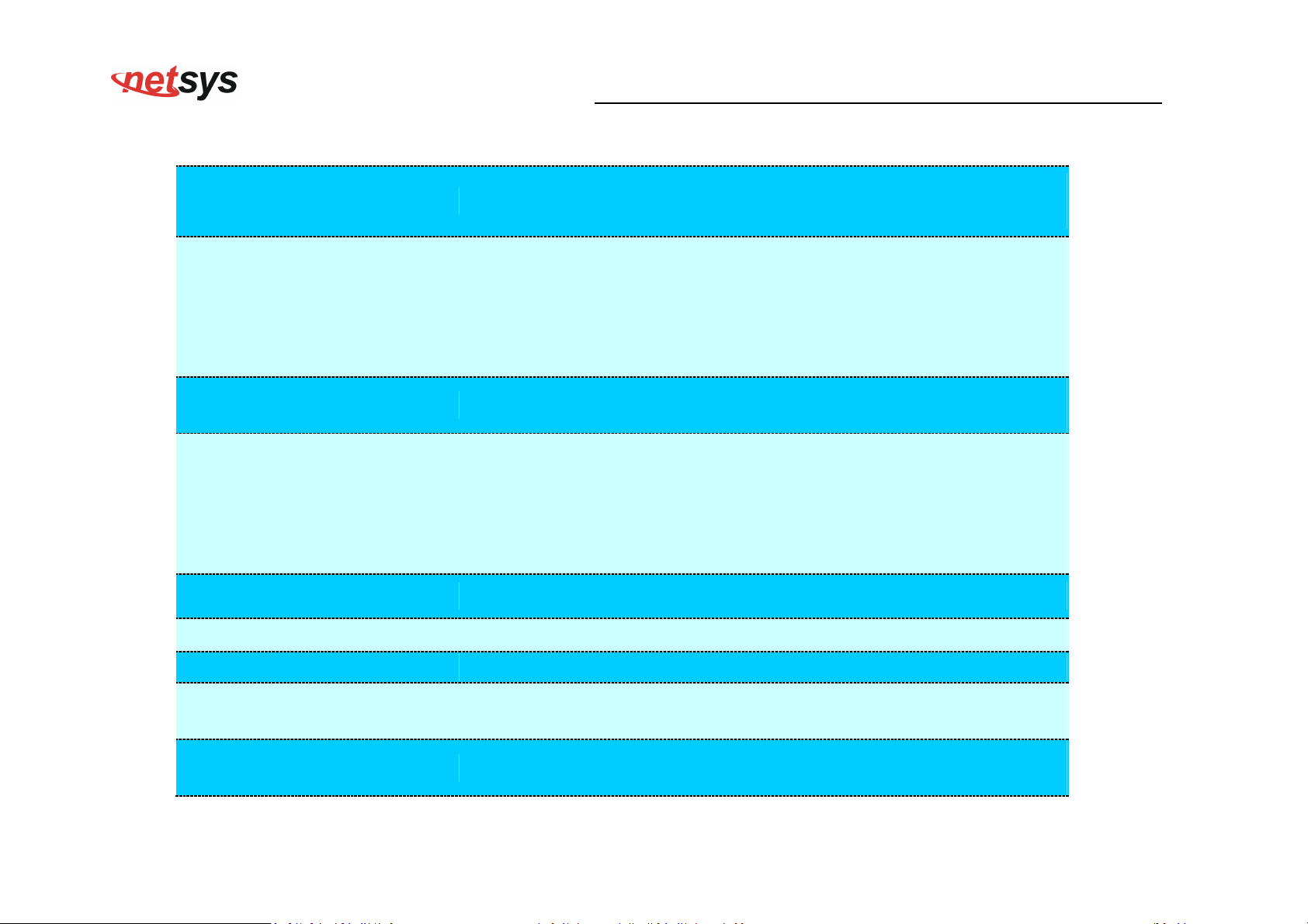
Product Specification
NV-700L VDSL2 Single Master Modem USER’S MANUAL Ver. A.2
Standard:
Physical Interface:
Flow control:
LED Indicators:
Switch method:
Typical Power Consumption:
IEEE802.3/802.3u standards
ITU-T G992.1/G992.3/G992.5/G993.1/ G993.2/G998.4 standards
4 x RJ-45 10/100 Mbps Ethernet port
1 x RJ-11 / Terminal combo for VDSL2 line port
1 x RJ-11 connector for POTS/ISDN device
1 x Reset Button for resetting to factory default
1 x USB2.0 for connecting USB dongle
Full duplex: IEEE 802.3x
Half duplex: Back pressure
1 x Power LED
4 x Link/Active Status for Ethernet port
1 x Link LED for VDSL2 port
1 x USB LED
1 x CO LED
Store and forward
4.4W (Full load, without USB port)
Power Input:
Input Voltage: 12 VDC (Commerical-grade power adapter)
EMI Compliant: FCC
EMC Certification:
EMS Compliant: CE mark
0°C ~ 50°C (32°F ~ 122°F)
Operating Temperature:
Fanless, free air cooling
63
Page 65
NV-700L VDSL2 Single Master Modem USER’S MANUAL Ver. A.2
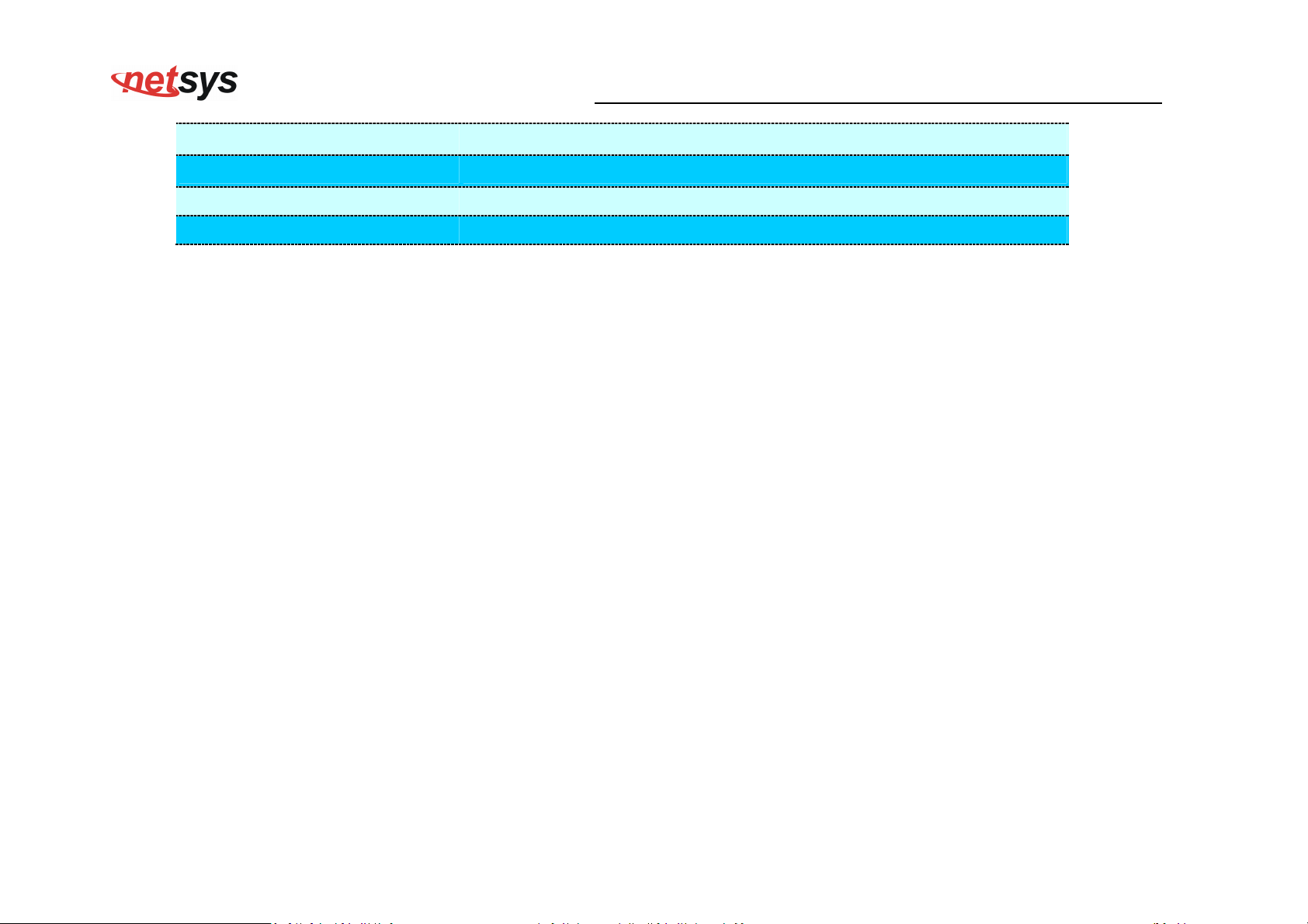
Storage Temperature:
Humidity:
Weight:
Dimensions:
-20°C ~ 70°C (-4°F ~158°F)
10% to 90% (non-condensing)
About 0.4 kgs
184 x 146 x 40 mm ( 7.2" x 5.74" x 1.57”)
64
Page 66
2.
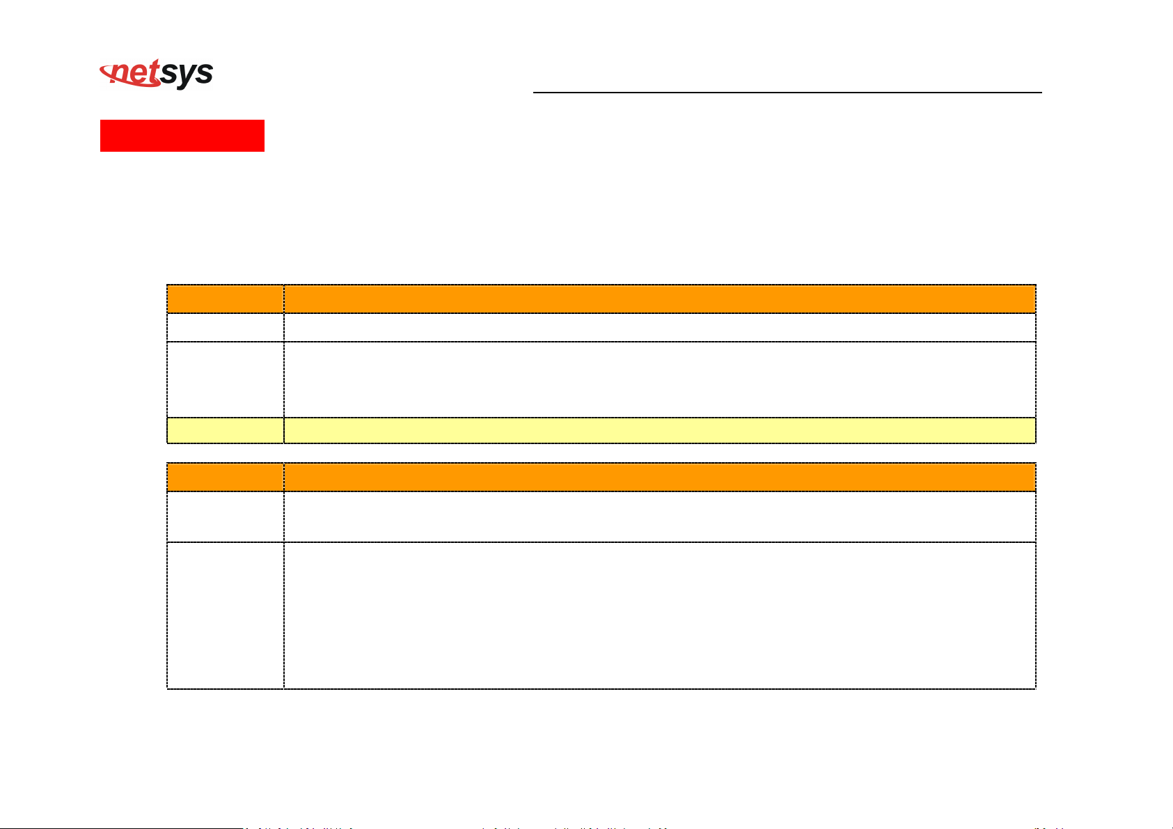
Appendix C: Troubleshooting
Diagnosing the Modem’s Indicators
The modem can be easily monitored through its comprehensive panel indicators. These indicators assist the network
manager in identifying problems the hub may encounter. This section describes common problems you may encounter
and possible solutions.
NV-700L VDSL2 Single Master Modem USER’S MANUAL Ver. A.2
1. Symptom:
Cause:
Solution:
Note:
Symptom:
Cause:
Solution:
POWER indicator does not light up (green) after power on.
Defective External power supply
Check the power plug by plugging in another that is functioning properly. Check the power cord with
another device. Check the terminal block make sure to fasten the power cord. If these measures fail
to resolve the problem, have the unit power supply replaced by a qualified distributor.
Please refer to power status table to check power input status. Section 3.3
Link indicator does not light up (green) after making a connection.
Network interface (ex. a network adapter card on the attached device), network cable, or switch port
is defective.
2.1 Verify that the switch and attached device are power on.
2.2 Be sure the cable is plugged into both the switch and corresponding device.
2.3 Verify that the proper cable type is used and its length does not exceed specified limits.
2.4 Check the modem on the attached device and cable connections for possible defects.
2.5 Make sure that the phone wire must be connecting NV-700L first, when powered on.
2.6 Replace the defective modem or cable if necessary.
2.7 Or try to change band profile as 17a for getting long reach
65
Page 67
NV-700L VDSL2 Single Master Modem USER’S MANUAL Ver. A.2
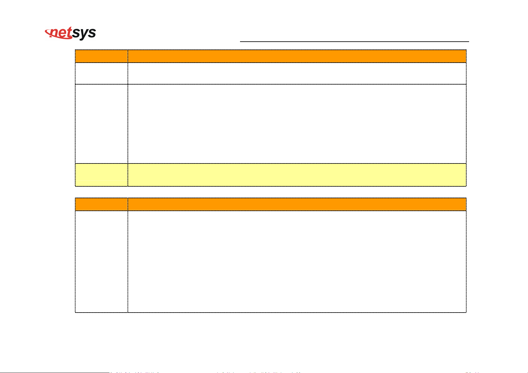
3. Symptom:
Cause:
VDSL Link cannot be established.
VDSL setting failure or phone cable length is over the specification limit.
3.1 Please make sure that the phone wire must be connected between NV-700L(CO) side and CPE
side when both are power on. NV-700L(CO) side will do link speed function depending on
phone wire length, therefore if NV-700L(CO) side can’t detect CPE Side over phone wire while
Solution:
both power on, this will cause the link to fail.
3.2 Please check phone wire, we recommend use 24-26 gauge with twisted pair and without rust.
3.3 Please reinsert power when change cable length or link time over 3 minutes.
3.4 Or try to change band profile as 17a for getting long reach.
Phone wire must meet CAT 3 standard or above and twisted pair, otherwise will cause more cross
Note:
talk issue to reduce VDSL power driver.
4. Question:
What is VDSL2? (Only reference)
Very-high-speed digital subscriber line 2 (VDSL2) is an access technology that exploits the existing
infrastructure of copper wires that were originally deployed for traditional telephone service. It can
be deployed from central offices, from fiber-optic connected cabinets located near the customer
premises, or within buildings. It was defined in standard ITU-T G.993.2 finalized in 2005.
Answer:
VDSL2 was the newest and most advanced standard of digital subscriber line (DSL) broadband
wireline communications. Designed to support the wide deployment of triple play services such as
voice, video, data, high definition television (HDTV) and interactive gaming, VDSL2 was intended to
enable operators and carriers to gradually, flexibly, and cost-efficiently upgrade existing xDSL
infrastructure.
66
Page 68
The protocol was standardized in the International Telecommunication Union telecommunications
sector (ITU-T) as Recommendation G.993.2. It was announced as finalized on 27 May 2005,[1] and
first published on 17 February 2006. Several corrections and amendments were published in 2007
through 2011.
VDSL2 is an enhancement to very-high-bitrate digital subscriber line (VDSL), Recommendation
G.993.1. It permits the transmission of asymmetric and symmetric aggregate data rates up to 200
Mbit/s downstream and upstream on twisted pairs using a bandwidth up to 30 MHz.
VDSL2 deteriorates quickly from a theoretical maximum of 250 Mbit/s at source to 100 Mbit/s at 0.5
km (1,600 ft) and 50 Mbit/s at 1 km (3,300 ft), but degrades at a much slower rate from there, and
still outperforms VDSL. Starting from 1.6 km (1 mi) its performance is equal to ADSL2+.
ADSL-like long reach performance is one of the key advantages of VDSL2. LR-VDSL2 enabled
NV-700L VDSL2 Single Master Modem USER’S MANUAL Ver. A.2
systems are capable of supporting speeds of around 1–4 Mbit/s (downstream) over distances of 4–5
km (2.5–3 miles), gradually increasing the bit rate up to symmetric 100 Mbit/s as loop-length
shortens. This means that VDSL2-based systems, unlike VDSL1 systems, are not limited to short
local loops or MTU/MDUs only, but can also be used for medium range applications.
67
Page 69
or my home. I was told any VDSL2 modem
would replace and give me higher communication speeds. It doesn’t get me internet when hooked up.
NV-700L VDSL2 Single Master Modem USER’S MANUAL Ver. A.2
5. Symptom:
Connected the CO modem with CPE Modem within 300 meters RJ-11 phone cable got only less
than 10 Mbit/s.
Some testing program which is base on TCP/IP protocol such as FTP, Iperf, NetIQ, the bandwidth of
Cause:
testing outcome will be limited by TCP window size.
We recommend to test VDSL2 bandwidth best by Smartbit equipment, if you don't have Smartbit,
Solution:
we recommend test that by IPERF program, and TCP window size must be settled max. 64k, the
parameter as iperf –c server IP address –i 1 –t 50 –w 65535 for client side.
I just bought a NV-700L to replace my Quest DSL modem f
6. Question:
All lights come on but no Link light. Is this the complete wrong application for this unit?
Re: Please note NV-700L is a Master side(CO side), it must be connected to the NV-720R(CPE side)
Answer:
to work. Band profile and band plan setting must be compatible to each other .
68
Page 70
NV-700L VDSL2 Single Master Modem USER’S MANUAL Ver. A.2
7. Question:
Answer:
We need to set up a default gateway on a NV-700L pair which are in Bridge mode, as they want to
manage the units from a different network.
When the application is used within the LAN, the switch(bridged) mode is not necessary to set up a
gateway .However, if the application crosses various network segments (LAN to WAN or WAN to
LAN), you must set up a gateway to connect different network segment.
Regarding how to configure a default gateway at switch(bridged) mode for crossing various network
segments .
Configuration gateway example from static routing:
Destination LAN IP: 0-0-0-0
Subnet Mask: 0-0-0-0
Gateway: 255-255-255-0
Note: Static Routing functionality is used to define the connected Gateway between the LAN and
WAN.
8. Question:
What can I do if I forgot my password.
If you forgot your password, you must reset your modem. Unfortunately this process will change all
your settings back to the factory defaults. To reset the modem, locate the reset on the rear panel of
Answer:
the unit. With the modem powered on, use a paperclip to hold the button down for over 5 seconds.
Release the button and the modem will go through its reboot process. The default ip is
192.168.16.249. When logging in, the default username and password both are “admin”.
69
Page 71
NV-700L VDSL2 Single Master Modem USER’S MANUAL Ver. A.2
9. Question:
Answer:
What is the maximum Ethernet frame MTU for these modems?
NV-700L maximum Ethernet frame MTU is 1518 bytes.
70
Page 72

System Diagnostics
Power and Cooling Problems
If the POWER indicator does not turn on when the power cord is plugged in, you may have a problem with the power
outlet, power cord, or internal power supply as explained in the previous section. However, if the unit power is off after
running for a while, check for loose power connections, power losses or surges at the power outlet. If you still cannot
isolate the problem, then the internal power supply may be defective. In this case, please contact your local dealer.
Installation
Verify that all system components have been properly installed. If one or more components appear to be
malfunctioning (e.g. the power cord or network cabling), test them in an alternate environment where you are sure that
all the other components are functioning properly.
Transmission Mode
The default method of selecting the transmission mode for RJ-45 ports is 10/100 Mbps ETHERNET, for RJ-11 port are
NV-700L VDSL2 Single Master Modem USER’S MANUAL Ver. A.2
auto-negotiation VDSL. Therefore, if the Link signal is disrupted (e.g. by unplugging the network cable and plugging it
back in again, or by resetting the power), the port will try to reestablish communications with the attached device via
auto-negotiation. If auto-negotiation fails, then communications are set to half duplex by default. Based on this type of
commercial-standard connection policy, if you are using a full-duplex device that does not support auto-negotiation,
communications can be easily lost (i.e. reset to the wrong mode) whenever the attached device is reset or experiences
a power fluctuation. The best way to resolve this problem is to upgrade these devices to a version that support
Ethernet and VDSL.
71
Page 73

Physical Configuration
If problems occur after altering the network configuration, restore the original connections, and try to track the problem
down by implementing the new changes, one step at a time. Ensure that cable distances and other physical aspects of
the installation do not exceed recommendations.
System Integrity
As a last resort verify the switch integrity with a power-on reset. Turn the power to the switch off and then on several
times. If the problem still persists and you have completed all the preceding diagnoses, then contact your dealer.
NV-700L VDSL2 Single Master Modem USER’S MANUAL Ver. A.2
72
Page 74

NV-700L VDSL2 Single Master Modem USER’S MANUAL Ver. A.2
Appendix E: Compliance Information
FCC Radio Frequency Interference Statement
This equipment has been tested and found to comply with the limits for a computing device, pursuant to Part 15 of FCC
rules. These limits are designed to provide reasonable protection against harmful interference when the equipment is
operated in a commercial environment. This equipment generates uses and can radiate radio frequency energy and, if not
installed and used in accordance with the instructions, may cause harmful interference to radio communications. However,
there is no guarantee that interference will not occur in a particular installation. If this equipment does cause harmful
interference to radio or television reception, which can be determined by turning the equipment off and on, the user is
encouraged to try to correct the interference by one or more of the following measures:
1. Reorient or relocate the receiving antenna.
2. Increase the separation between the equipment and receiver.
3. The equipment and the receiver should be connected to outlets on separate circuits.
4. Consult the dealer or an experienced radio/television technician for help.
Changes or modifications not expressly approved by the party responsible for compliance could void the user’s authority to
operate the equipment.
If this telephone equipment causes harm to the telephone network, the telephone company will notify you in advance that
temporary discontinuance of service may be required. But if advance notice isn’t practical, the telephone company will
notify the customer as soon as possible. Also, you will be advised of your right to file a complaint with the FCC if you believe
it is necessary.
73
Page 75

NV-700L VDSL2 Single Master Modem USER’S MANUAL Ver. A.2
The telephone company may make changes in its facilities, equipment, operations or procedures that could affect the
proper functioning of your equipment. If they do, you will be notified in advance in order for you to make necessary
modifications to maintain uninterrupted service.
This equipment may not be used on coin service provided by the telephone company. Connection to party lines is subject to
state tariffs.
FCC Warning
This equipment has been tested to comply with the limits for a Class A digital device, pursuant to Part 15
of the FCC Rules. These limits are designed to provide reasonable protection against harmful
interference when the equipment is operated in a commercial environment. This equipment can
generate, use, and radiate radio frequency energy and, if not installed and used in accordance with the
instruction manual, may cause harmful interference to radio communications. Operation of this equipment in a residential
area is likely to cause harmful interference in which case the user will be required to correct the interference at owner’s
expense.
CE Mark Warning
This is a class A product. In a domestic environment, this product may cause radio interference in which
case the user may be required to take adequate measures.
74
Page 76

WEEE Warning
NV-700L VDSL2 Single Master Modem USER’S MANUAL Ver. A.2
To avoid the potential effects on the environment and human health as a result of the presence of
hazardous substances in electrical and electronic equipment, end users of electrical and electronic
equipment should understand the meaning of the crossed-out wheeled bin symbol. Do not dispose of
WEEE as unsorted municipal waste and have to collect such WEEE separately.
75
Page 77

NV-700L VDSL2 Single Master Modem USER’S MANUAL Ver. A.2
Warranty
The original product that the owner delivered in this package will be free from defects in material and workmanship for one
year parts after purchase.
There will be a minimal charge to replace consumable components, such as fuses, power transformers, and mechanical
cooling devices. The warranty will not apply to any products which have been subjected to any misuse, neglect or
accidental damage, or which contain defects which are in any way attributable to improper installation or to alteration or
repairs made or performed by any person not under control of the original owner.
The above warranty is in lieu of any other warranty, whether express, implied, or statutory, including but not limited to any
warranty of merchantability, fitness for a particular purpose or any warranty arising out of any proposal, specification or
sample. We shall not be liable for incidental or consequential damages. We neither assume nor authorize any person to
assume for it any other liability.
WARNING:
1.DO NOT TEAR OFF OR REMOVE THE WARRANTY STICKER AS SHOWN, OR THE WARRANTY IS VOID.
2.WARRANTY VOID IF USE COMMERCIAL-GRADE POWER ADAPTER IS USED AT HARSH ENVIRONMENTS.
76
Page 78
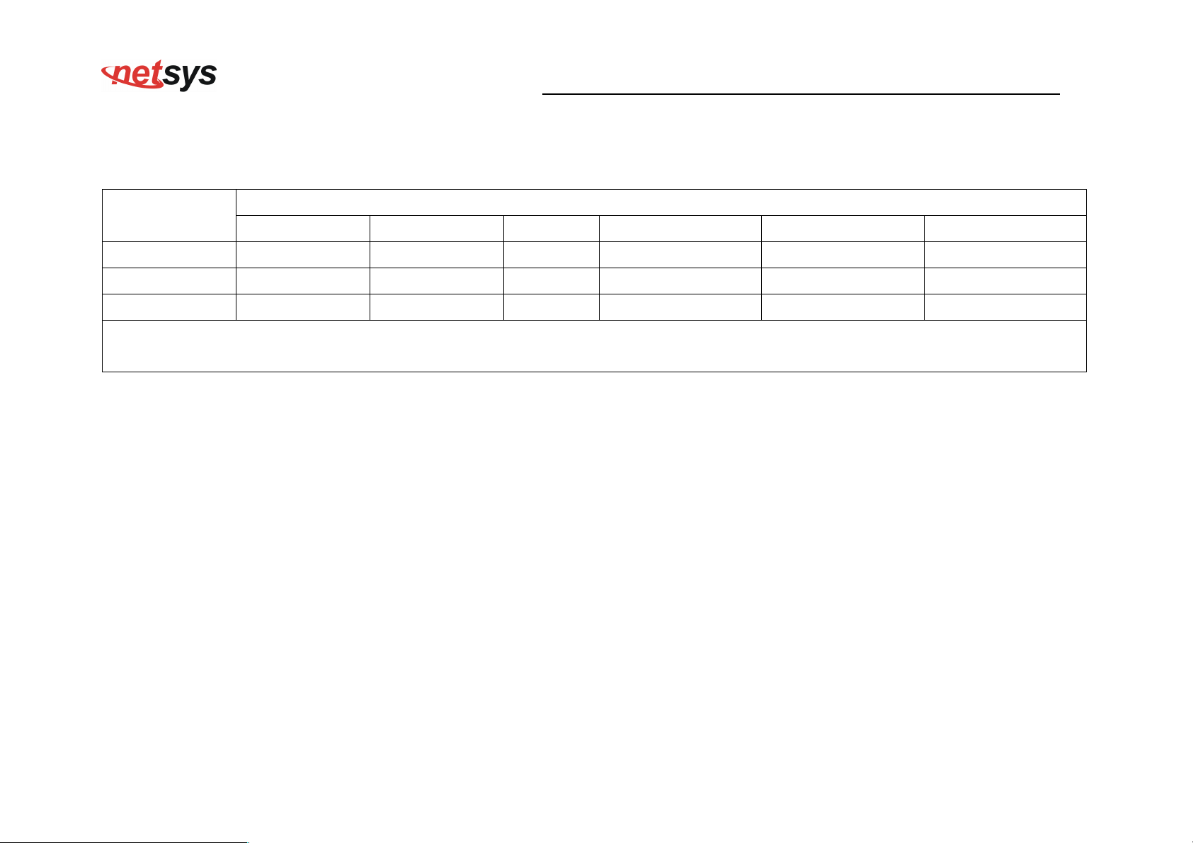
Chinese SJ/T 11364-2014
NV-700L VDSL2 Single Master Modem USER’S MANUAL Ver. A.2
部件名称
有 毒 有 害 物 质 或 元 素
铅(Pb) 汞(Hg) 镉(Cd) 六价铬[Cr(VI)] 多溴联苯(PBB) 多溴二苯醚(PBDE)
结构壳体 ○ ○ ○ ○ ○ ○
电路组 ○ ○ ○ ○ ○ ○
包装及配件 ○ ○ ○ ○ ○ ○
○:表示该有毒物质在该部件所有均质材料中的含量均在 GB/T 26572 标准规定的限量要求以下。
╳:表示该有毒物质至少在该部件的某依均质材料中的含量超出 GB/T 26572 标准规定的限量要求。
上述规范仅适用於中国法律
77
 Loading...