

Page 1

N
V
-
6
0
0
W
I
N
V
-
6
0
0
N
V
-
6
0
M
a
n
a
g
e
d
I
n
d
u
s
t
r
i
a
l
G
r
a
d
M
a
n
a
g
e
d
I
n
d
u
s
t
r
i
a
l
G
M
a
n
a
g
e
d
I
n
d
u
s
t
r
i
a
l
G
r
r
a
a
d
d
e
e
e
0
W
W
W
W
W
I
I
i
r
e
l
e
s
s
V
D
S
L
2
R
o
u
t
e
r
i
r
e
l
e
s
s
V
D
S
L
2
R
o
u
t
i
r
e
l
e
s
s
V
D
S
L
2
R
o
u
t
e
e
r
r
U
U
U
S
S
S
E
E
E
R
R
R
’
’
’
S
S
S
M
M
M
A
A
A
N
N
N
U
U
U
A
A
A
L
L
L
Page 2
NV-600WI Managed Industrial Grade Wireless VDSL2 Router USER’S MANUAL Ver. A2
Copyright
Copyright © 2012 by National Enhance Technology Corp. All rights reserved.
Trademarks
NETSYS is a trademark of National Enhance Technology Corp.
Other brand and product names are registered trademarks or trademarks of their respective holders.
Legal Disclaimer
The information given in this document shall in no event be regarded as a guarantee of conditions or characteristics. With respect
to any examples or hints given herein, any typical values stated herein and/or any information regarding the application of the
device, National Enhance Technology Corp. hereby disclaims any and all warranties and liabilities of any kind, including without
limitation warranties of non-infringement of intellectual property rights of any third party.
Statement of Conditions
In the interest of improving internal design, operational function, and/or reliability, NETSYS reserves the right to make changes to
the products described in this document without notice. NETSYS does not assume any liability that may occur due to the use or
application of the product(s) or circuit layout(s) described herein.
Maximum signal rate derived from IEEE Standard specifications. Actual data throughput will vary. Network conditions and
environmental factors, including volume of network traffic, building materials and construction, and network overhead, lower actual
data throughput rate. Netsys does not warrant that the hardware will work properly in all environments and applications, and makes
no warranty and representation, either implied or expressed, with respect to the quality, performance, merchantability, or fitness for
a particular purpose. Make sure you follow in line with the environmental conditions to use this product.
1
Page 3
NV-600WI Managed Industrial Grade Wireless VDSL2 Router USER’S MANUAL Ver. A2
Foreword: VDSL2 Router solution
Attention:
Be sure to read this manual carefully before using this product. Especially Legal Disclaimer, Statement
of Conditions and Safety Warnings.
Netsys' NV-600WI is an industrial managed wireless VDSL2 router that leverages the extraordinary bandwidth promise of VDSL2
technology and compliant with the IEEE 802.11n standard. It can enhance wireless speeds up to 300 Mbps* and extend the
coverage. NV-600WI also supports one-touch Wi-Fi Protected Setup (WPS) with the push button that only takes a few seconds to
setup a secured wireless network.
In addition to using a DIN-Rail design that is quick, easy and economical to install and maintain, it offers high-performance
broadband/multimedia services to industrial environments such as Factories, MRT, Train stations, Ticket vending machines, Parking
systems, Monitoring systems and point to point applications.
Wireless LAN enables high mobility so WLAN users can simultaneously access all LAN facilities just like on a wired LAN as well as
Internet access. The NV-600WI is equipped with a wireless LAN interface compliant with the standard IEEE 802.11n protocol.
To boost its performance even further, the NV-600WI is also loaded with an advanced wireless technology to lift up the data rate up to
300 Mbps*. You can finally smoothly enjoy a wide range of apps on your smart phone, tablet or smart TV.
(*). The maximum wireless data transfer rate is derived from IEEE Standard 802.11 specifications. Actual data transfer rate will vary from network environment
including: distance, network traffic, building site materials/construction, interference from other wireless devices, and other adverse conditions.
Caution:
The NV-600WI is for indoor applications only. This product does not have waterproof protection, please do not use in outdoor
applications.
2
Page 4
NV-600WI Managed Industrial Grade Wireless VDSL2 Router USER’S MANUAL Ver. A2
Safety Warnings
For your safety, be sure to read and follow all warning notices and instructions before using the device.
DO NOT open the device or unit. Opening or removing the cover may expose you to dangerous high voltage points or other
risks. ONLY qualified service personnel can service the device. Please contact your vendor for further information.
Use ONLY the dedicated power supply for your device. Connect the power to the right supply voltage (110V AC used for
North America and 230V AC used for Europe. NV-600WI supports 12 to 48 VDC dual power input (Redundant power)).
Place connecting cables carefully so that no one will step on them or stumble over them. DO NOT allow anything to rest on
the power cord and do NOT locate the product where anyone can work on the power cord.
DO NOT install nor use your device during a thunderstorm. There may be a remote risk of electric shock from lightning.
DO NOT expose your device to dampness, dust or corrosive liquids.
DO NOT use this product near water, for example, in a wet basement or near a swimming pool.
Connect ONLY suitable accessories to the device.
Make sure to connect the cables to the correct ports.
DO NOT obstruct the device ventilation slots, as insufficient air flow may harm your device.
DO NOT place items on the device.
DO NOT use the device for outdoor applications directly, and make sure all the connections are indoors or have waterproof
protection place.
Be careful when unplugging the power, because it may produce sparks.
Keep the device and all its parts and accessories out of the reach of children.
Clean the device using a soft and dry cloth rather than liquid or atomizers. Power off the equipment before cleaning it.
This product is recyclable. Dispose of it properly.
3
Page 5

NV-600WI Managed Industrial Grade Wireless VDSL2 Router USER’S MANUAL Ver. A2
TABLE OF CONTENTS
COPYRIGHT ........................................................................................................................................................ 1
FOREWORD: VDSL2 ROUTER SOLUTION ........................................................................................................ 2
SAFETY WARNINGS ........................................................................................................................................... 3
1.1 Check List .................................................................................................................................................................................... 10
CHAPTER 2. INSTALLING THE ROUTER ......................................................................................................... 11
2.1 Hardware Installation.................................................................................................................................................................... 11
2.2 Pre-installation Requirements ...................................................................................................................................................... 11
2.3 General Rules .............................................................................................................................................................................. 12
2.4 Connecting the Router ................................................................................................................................................................. 13
2.5 Connecting the RJ-11 / RJ-45 Ports ............................................................................................................................................. 14
2.6 Terminal Block and DIN-Rail mount installation............................................................................................................................15
2.7 Industrial VDSL2 Application ........................................................................................................................................................ 16
4
Page 6
NV-600WI Managed Industrial Grade Wireless VDSL2 Router USER’S MANUAL Ver. A2
CHAPTER 3. HARDWARE DESCRIPTION........................................................................................................ 20
3.1 Front Panel................................................................................................................................................................................... 21
3.2 Front Indicators ............................................................................................................................................................................ 22
3.3 Rear Panel ................................................................................................................................................................................... 24
3.4 Side Panel.................................................................................................................................................................................... 25
CHAPTER 4. CONFIGURING THE NV-600WI VIA WEB BROWSER ................................................................ 30
4.1 Login ............................................................................................................................................................................................ 31
4.1.1 Home ..................................................................................................................................................................................... 33
4.1.2 Quick Setup ........................................................................................................................................................................... 35
4.2 Select the Menu Level.................................................................................................................................................................. 43
4.3 Select “SYSTEM” ......................................................................................................................................................................... 44
4.3.1 Host Name Configuration....................................................................................................................................................... 45
4.3.2 System Time.......................................................................................................................................................................... 46
4.3.3 Administrator Settings (User Account Management) .............................................................................................................48
4.3.4 Web Settings ......................................................................................................................................................................... 50
4.3.5 Software/Firmware Upgrade.................................................................................................................................................. 51
4.3.6 Configuration Settings ........................................................................................................................................................... 52
4.3.7 System Log............................................................................................................................................................................ 55
5
Page 7

NV-600WI Managed Industrial Grade Wireless VDSL2 Router USER’S MANUAL Ver. A2
4.3.8 SSL Certificate....................................................................................................................................................................... 58
4.3.9 Reset ..................................................................................................................................................................................... 59
4.4 Select “Statistics”.......................................................................................................................................................................... 60
4.4.1 LAN........................................................................................................................................................................................ 61
4.4.2 WAN ...................................................................................................................................................................................... 63
4.5 Select “xDSL” ............................................................................................................................................................................... 65
4.5.1 xDSL Status ...........................................................................................................................................................................66
4.5.2 Vectoring Mode selection....................................................................................................................................................... 68
4.6 Select “WAN”................................................................................................................................................................................ 70
4.6.1 WAN Mode Selection............................................................................................................................................................. 71
4.6.2 Auto Detect Setting ................................................................................................................................................................ 73
4.6.3 WAN Channel Configuration.................................................................................................................................................. 76
4.6.4 VLAN Channel Configuration................................................................................................................................................. 80
4.6.5 WAN Setting .......................................................................................................................................................................... 83
4.6.6 WAN Status............................................................................................................................................................................97
4.6.7 DNS ..................................................................................................................................................................................... 101
4.6.8 DDNS .................................................................................................................................................................................. 103
4.6.9 OAM Configuration .............................................................................................................................................................. 105
4.7 Select “LAN”............................................................................................................................................................................... 109
4.7.1 LAN ARP List....................................................................................................................................................................... 110
4.7.2 LAN Settings........................................................................................................................................................................ 111
6
Page 8

NV-600WI Managed Industrial Grade Wireless VDSL2 Router USER’S MANUAL Ver. A2
4.7.3 UPnP Devices List ............................................................................................................................................................... 121
4.7.4 LAN Switch Port Setting....................................................................................................................................................... 122
4.7.5 LAN Port Status ................................................................................................................................................................... 123
4.7.6 VLAN Settings ..................................................................................................................................................................... 124
4.8 Select “Route” ............................................................................................................................................................................ 126
4.8.1 Static Routing....................................................................................................................................................................... 127
4.8.2 RIP Support ......................................................................................................................................................................... 130
4.8.3 Routing Table List ................................................................................................................................................................ 133
4.9 Select “Wireless” ........................................................................................................................................................................ 136
4.9.1 Radio Settings ..................................................................................................................................................................... 137
4.9.2 Security Settings.................................................................................................................................................................. 139
4.9.3 WMM Settings ..................................................................................................................................................................... 144
4.9.4 WPS Settings....................................................................................................................................................................... 146
4.9.5 Station List ........................................................................................................................................................................... 148
4.10 Select “Firewall”........................................................................................................................................................................ 149
4.10.1 Firewall Setting .................................................................................................................................................................. 150
4.10.2 IPv6 Firewall Setting .......................................................................................................................................................... 151
4.10.3 Packet Filtering .................................................................................................................................................................. 153
4.10.4 URL Filtering...................................................................................................................................................................... 167
4.10.5 Parental Control................................................................................................................................................................. 169
4.10.6 Application Server Settings................................................................................................................................................ 171
4.10.7 Access Control List (ACL).................................................................................................................................................. 173
7
Page 9

NV-600WI Managed Industrial Grade Wireless VDSL2 Router USER’S MANUAL Ver. A2
4.11 NAT...........................................................................................................................................................................................175
4.11.1 NAT Settings ......................................................................................................................................................................176
4.11.2 Virtual Server ..................................................................................................................................................................... 177
4.11.3 Port Triggering ................................................................................................................................................................... 181
4.11.4 DMZ ................................................................................................................................................................................... 185
4.11 QoS .......................................................................................................................................................................................... 187
4.11.1 QoS Settings...................................................................................................................................................................... 188
4.11.2 Queue Configuration.......................................................................................................................................................... 191
4.11.3 Class Configuration............................................................................................................................................................ 195
4.12 Multicast ................................................................................................................................................................................... 201
4.12.1 Proxy Settings.................................................................................................................................................................... 202
4.12.2 Snooping Settings.............................................................................................................................................................. 204
4.12.3 Advanced Settings ............................................................................................................................................................. 206
4.13 IPsec ........................................................................................................................................................................................ 208
4.13.1 Tunnel Mode ...................................................................................................................................................................... 209
4.14 IPv6 .......................................................................................................................................................................................... 212
4.14.1 IPv6 Setting ....................................................................................................................................................................... 213
4.14.2 6RD Configuration ............................................................................................................................................................. 215
4.14.3 DS-Lite Configuration ........................................................................................................................................................ 217
4.15 Diagnostics............................................................................................................................................................................... 219
8
Page 10
4.15.1 Diagnostic Test Suite .........................................................................................................................................................220
NV-600WI Managed Industrial Grade Wireless VDSL2 Router USER’S MANUAL Ver. A2
APPENDIX A: CABLE REQUIREMENTS ......................................................................................................... 222
APPENDIX B: PRODUCT SPECIFICATION..................................................................................................... 225
APPENDIX C: ROUTER/BRIDGED MODE SELECT........................................................................................ 229
APPENDIX D: NV-600LI & NV-600WI/AI COMPATIBILITY TABLE ................................................................... 234
APPENDIX E: IP-30 PROTECTION OF METAL CASE..................................................................................... 236
APPENDIX F: TROUBLESHOOTING............................................................................................................... 238
APPENDIX G: COMPLIANCE INFORMATION ................................................................................................. 248
WARRANTY ..................................................................................................................................................... 251
CHINESE SJ/T 11364-2006.............................................................................................................................. 252
9
Page 11
VDSL2
4
NV-600WI Managed Industrial Grade Wireless VDSL2 Router USER’S MANUAL Ver. A2
Chapter 1. Unpacking Information
1.1 Check List
Thank you for choosing Netsys NV-600WI. Before installing the router, please verify the contents inside the package.
Package Contents:
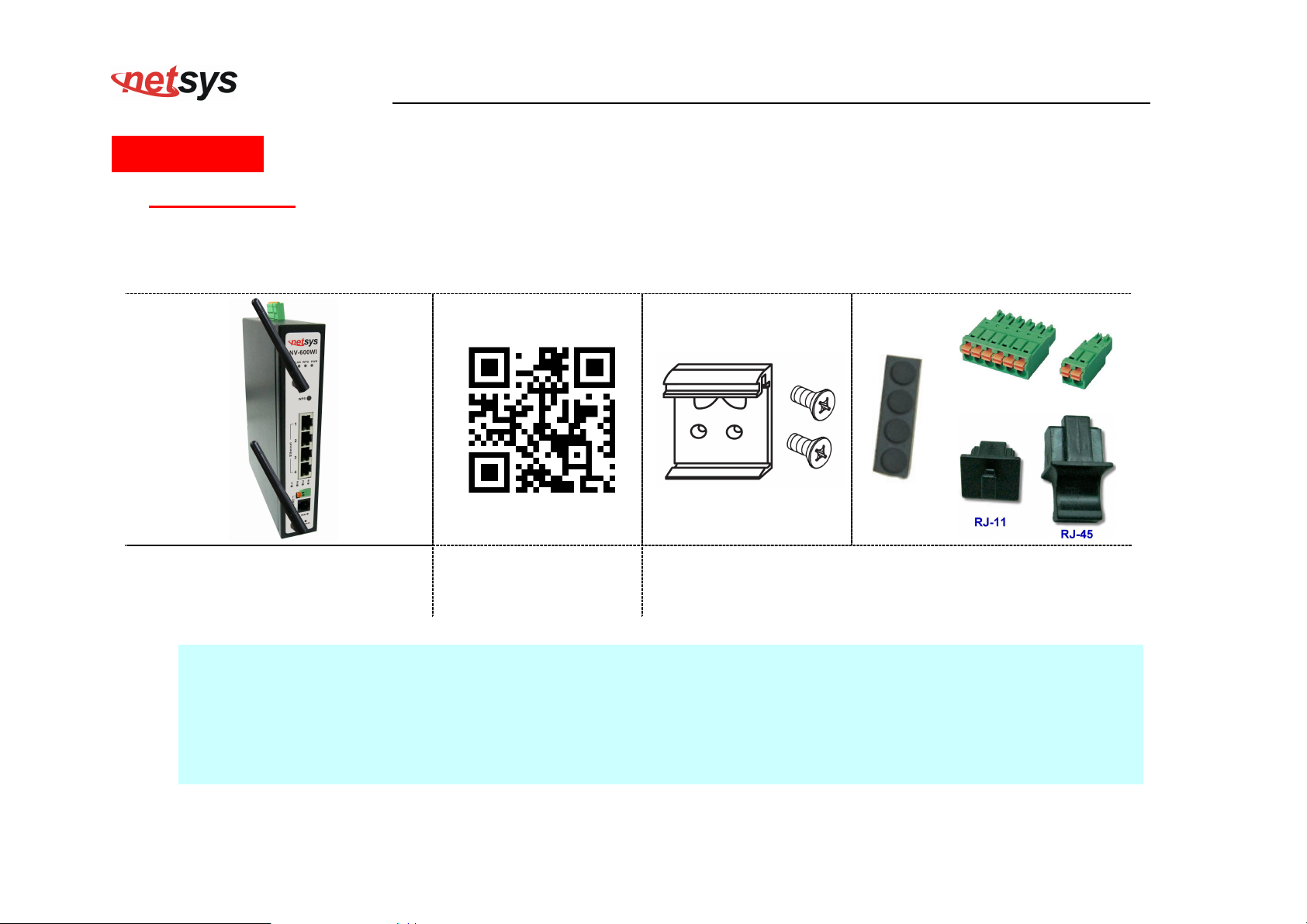
1 x Industrial grade wireless
CPE router (Contain two antennas)
Notes:
1. Please inform your dealer immediately for any missing or damaged parts. If possible, retain the carton including the
original packing materials. Use them to repack the unit in case there is a need to return for repair.
2. If the product has any issue, please contact your local distributor.
3. Please use the provided protective caps for unused ports.
4. Please look for the QR code on the bottom of the product, the user can launch the QR code scanning program to
scan and download the user’s manual electronic format file. Above QR code icon is for reference.
1 x QR code for user’s
manual hyperlink.
Accessory Kit : 1 x DIN-Rail mounting plate, 2 x screws,
x Rubber Feet, Protective caps (RJ-11*1, RJ-45*3), 1 x
6pin Terminal Block, 1 x 2pin Terminal Block
10
Page 12

NV-600WI Managed Industrial Grade Wireless VDSL2 Router USER’S MANUAL Ver. A2
Chapter 2. Installing the Router
2.1 Hardware Installation
This chapter describes how to install the router and establish the network connections. The NV-600WI may be installed
on any level surface (e.g. a table or shelf). However, please take note of the following minimum site requirements
before you begin.
2.2 Pre-installation Requirements
Before you start the actual hardware installation, make sure you can provide the right operating environment, including
power requirements, sufficient physical space, and proximity to other network devices that are to be connected.
Verify the following installation requirements:
• Power requirements: DC 12 to 48VDC redundant power.
• The router should be located in a cool dry place, with at least 10cm/4in of space at the front and back for
ventilation.
• Place the router away from direct sunlight, heat sources, or areas with a high amount of electromagnetic
interference.
• Check if the network cables and connectors needed for installation are available.
• Do not install phone lines strapped together with AC power lines, or telephone office line with voice signal.
• Avoid installing this device with radio amplifying stations nearby or transformer stations nearby.
11
Page 13
2.3 General Rules
Before making any connections to the router, please note the following rules:
• Ethernet Port (RJ-45)
• VDSL2 Port (RJ-11)
NV-600WI Managed Industrial Grade Wireless VDSL2 Router USER’S MANUAL Ver. A2
All network connections to the router Ethernet ports must be made using Category 5 UTP/STP or above for
100 Mbps, Category 3, 4 UTP for 10Mbps.
No more than 100 meters of cabling may be used between the MUX or HUB and an end node.
All network connections to the RJ-11port must use 24~26 gauge with twisted pair phone wiring.
We do not recommend the use of the telephone line 28 gauge or above.
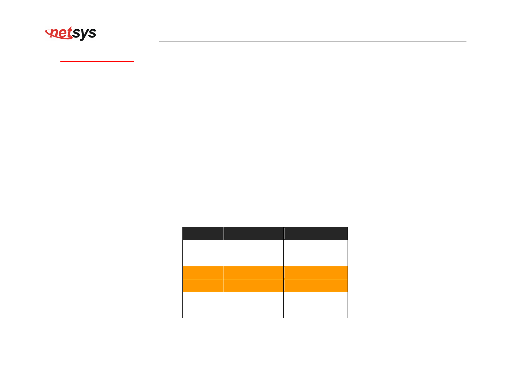
The RJ-11 connectors have six positions, two of which are wired. The router uses the center two pins. The
pin out assignment for these connectors is presented below.
Please note that the line port is no polarity, therefore user can reverse the two wires of the phone cable
when installed.
RJ-11 Pin out Assignments
Pin# MNEMONIC FUNCTION
1 NC Unused
2 NC Unused
3 DSL Used
4 DSL Used
5 NC Unused
6 NC Unused_
12
Page 14

2.4 Connecting the Router
The router has four Ethernet ports which support connection to Ethernet operation. The devices attached to these
ports must support auto-negotiation /10Base-T / 100Base-TX / 1000Base-TX unless they will always operate at half
duplex. Use any of the Ethernet ports to connect devices such as Monitor systems, Servers, Switches, bridges or
routers.
Notes:
1. The (RJ11/Terminal Block) Line port is used to connect the telephone that is connected to VDSL2 CO and CPE
router (Point-to-point solution).
2. Use the provided protective caps for unused ports to avoid dust intrusion.
3. The Slave device (CPE) must be connected to the Master device (CO) through the telephone wire. The Slave
cannot be connected to another Slave, and the Master cannot be connected to another Master.
NV-600WI Managed Industrial Grade Wireless VDSL2 Router USER’S MANUAL Ver. A2
13
Page 15
NV-600WI Managed Industrial Grade Wireless VDSL2 Router USER’S MANUAL Ver. A2
2.5 Connecting the RJ-11 / RJ-45 Ports
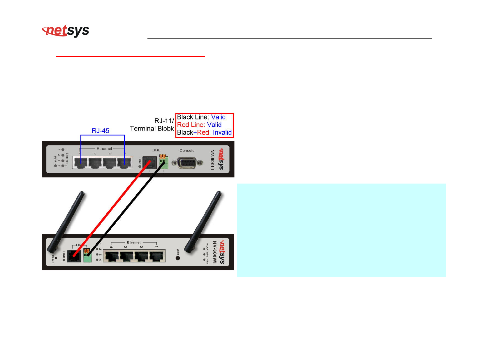
The line port has 2 connectors: RJ-11 and terminal block. It is used to connect with NV-600L (CO) using a single pair phone
cable to NV-600WI (CPE) bridge side (point to point solution). Take note that NV-600WI line port RJ-11 and terminal block
cannot be used at the same time. Either RJ-11 port is connected or terminal block is connected using straight connection.
(Figure 2.5).
When inserting a RJ-11 plug, make sure the tab on the plug
clicks into position to ensure that it is properly seated.
Do not plug a RJ-11 phone jack connector into the Ethernet
port (RJ-45 port). This may damage the router. Instead, use
only twisted-pair cables with RJ-45 connectors that conform to
Ethernet standard.
Notes:
1. Be sure each twisted-pair cable (RJ-45 Ethernet cable) does
not exceed 100 meters (333 feet).
2. We advise using Category 5~7 UTP/STP cables for making
Bridge or Router connections to avoid any confusion or
inconvenience in the future when you attach high bandwidth
devices.
3. Use 24 ~ 26 gauge twisted pair phone wiring, we do not
recommend 28 gauge or above.
4. Be sure phone wire has been installed before the NV-600WI
Figure 2.5 NV-600WI line ports straight connection
boot.
14
Page 16
NV-600WI Managed Industrial Grade Wireless VDSL2 Router USER’S MANUAL Ver. A2
2.6 Terminal Block and DIN-Rail mount installation
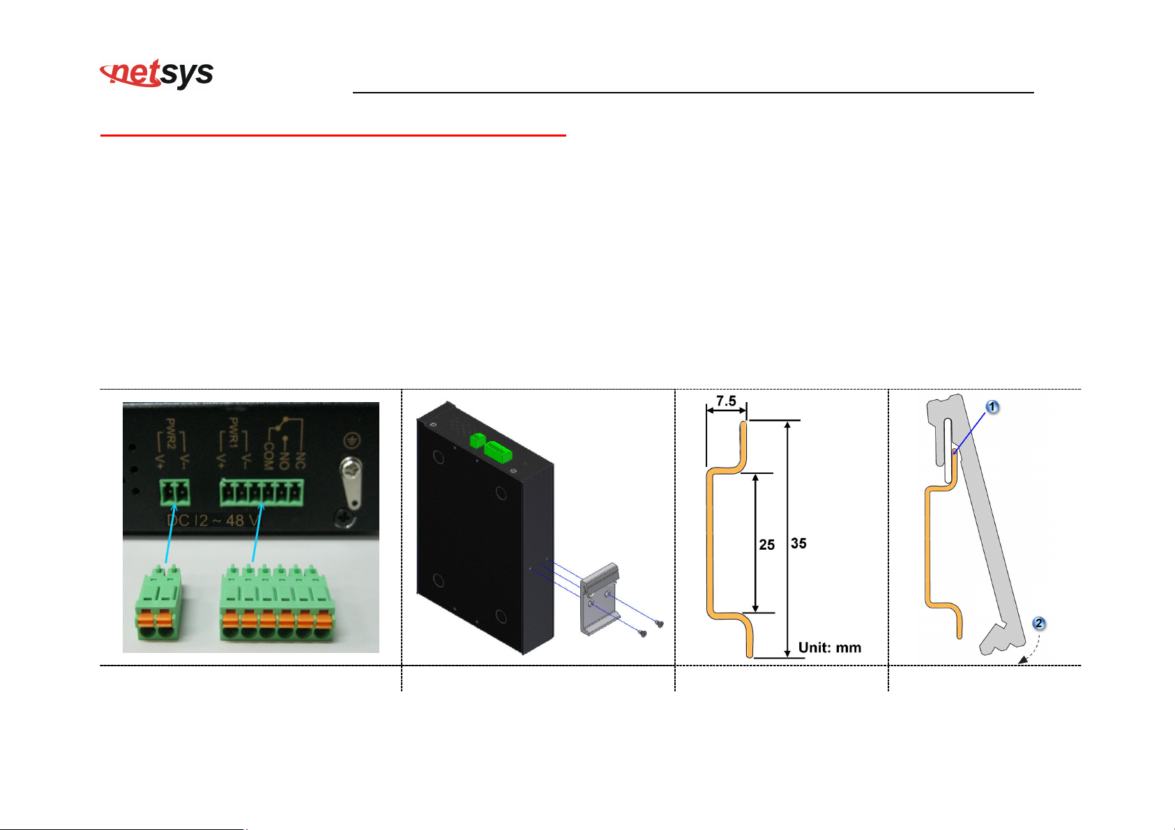
This section describes how to install the Terminal Block and DIN-Rail to the router, if you do not install the DIN-Rail, please paste
the 4 rubber feet at the bottom of the hulled to avoid scratches of metal housing.
Take out the “2pin / 6pin terminal block” from inside the accessory kit, and install to the router properly. (Figure 2.6.1)
Please refer to install the DIN-RAIL as following step:
1. Install the DIN-Rail mounting plate to the NV-600WI. (Figure 2.6.2)
2. Please use the suitable DIN-Rail to install, please refer to the dimensions of the DIN-Rail.(Figure 2.6.3)
3. Insert the top of the DIN-Rail into the top slots on the DIN-Rail mounting plate and the DIN-Rail mounting plate will snap into
place. (Figure 2.6.4)
Figure 2.6.1 Figure 2.6.2 Figure 2.6.3 Figure 2.6.4
15
Page 17
NV-600WI Managed Industrial Grade Wireless VDSL2 Router USER’S MANUAL Ver. A2
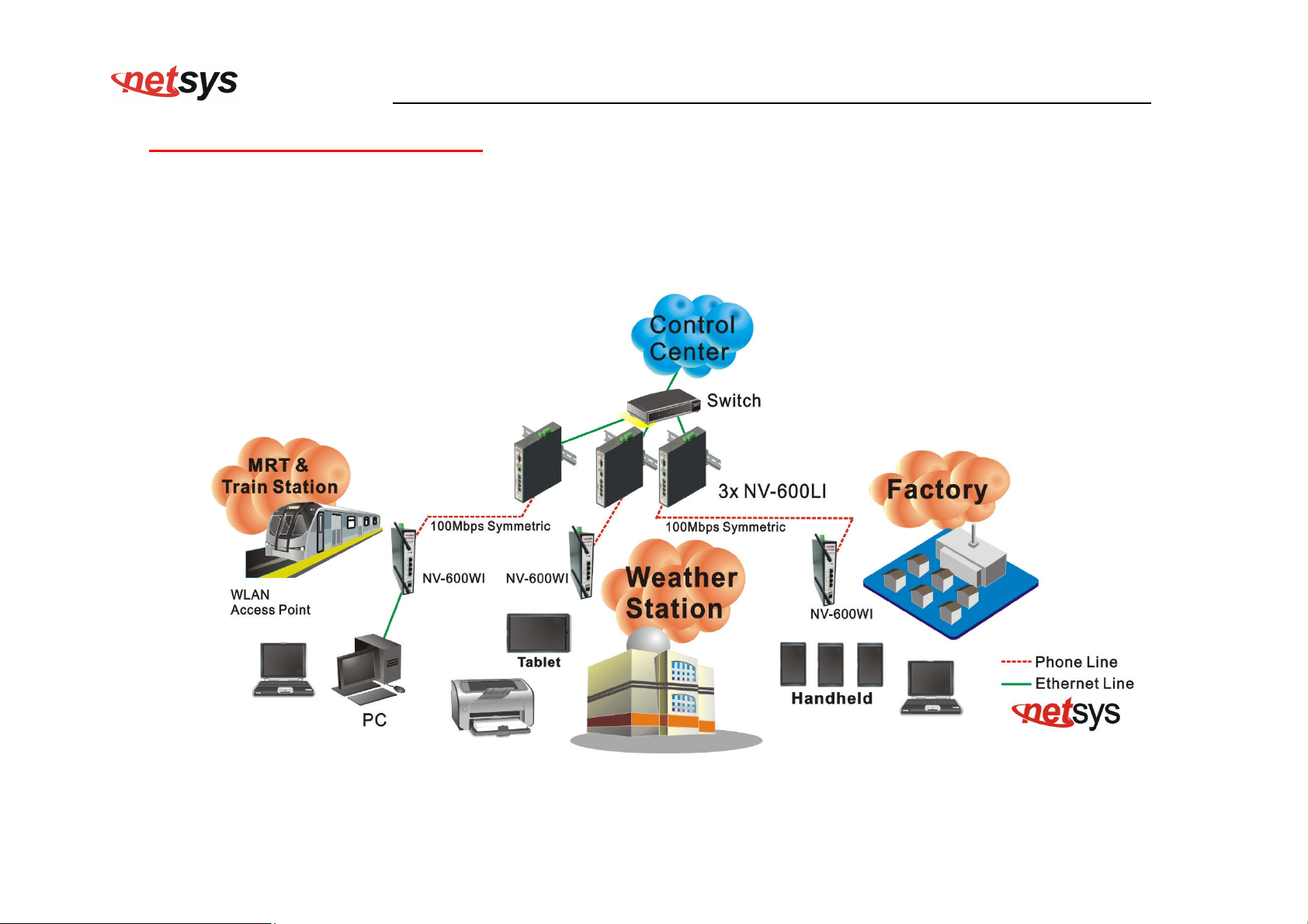
2.7 Industrial VDSL2 Application
The router’s line port supports 100Mbps/0.3km for data service across existing phone wiring. It is easy-to-use and do not requires
installation of additional wiring. Every modular phone jack in the home can become a port on the LAN. Networking devices can be
installed on a single telephone wire that can be installed within a suitable distance. (Figure 2.7)
Figure 2.7 NV-600WI applications
16
Page 18
NV-600WI Managed Industrial Grade Wireless VDSL2 Router USER’S MANUAL Ver. A2
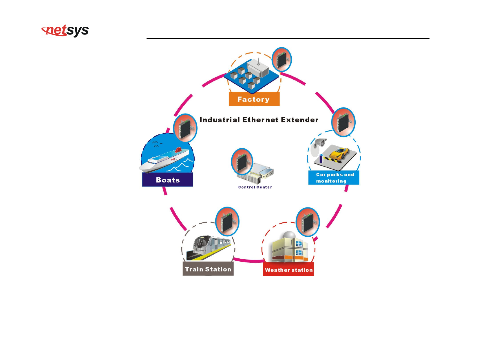
Figure 2.7.1 NV-600LI/WI industrial-grade application
17
Page 19

NV-600WI Managed Industrial Grade Wireless VDSL2 Router USER’S MANUAL Ver. A2
2.7.1 Connect the NV-600LI and the NV-600WI to the Line
The objective for VDSL2 is to pass high speed data over a twisted pair cable. In the setup, connect NV-600LI to NV-600WI
through phone wire (24~26 AWG) or line simulator or any other hardware representation of a cable network, with or without
noise injection and crosstalk simulations.
2.7.2 Connect the NV-600LI and the NV-600WI to LAN Devices
In the setup, usually an Ethernet tester serves as a representation of the LAN side as well as a representation of the WAN side.
2.7.3 Run Demos and Tests
The Ethernet tester may send data downstream as well as upstream. It also receives the data in order to check the integrity of
the data transmission. Different data rates can be tested under different line conditions.
2.7.4 Wireless Basics
In recent years, the market for wireless communications has enjoyed tremendous growth. Wireless technology now reaches or
is capable of reaching virtually every location on the surface of the earth. Hundreds of millions of people exchange information
every day via wireless communication products. Anyone can bring a built-in WLAN client Smartphone, tablet or notebook into a
meeting room for a conference without laying a clot of LAN cable or drilling holes everywhere. Wireless LAN enables high
mobility so WLAN users can simultaneously access all LAN facilities just like on a wired LAN as well as Internet access. The
NV-600WI is equipped with a wireless LAN interface compliant with the standard IEEE 802.11n protocol. To boost its
performance even further, the NV-600WI is also loaded with an advanced wireless technology to lift up the data rate up to 300
Mbps. You can finally smoothly enjoy a wide range of apps on your smart phone, tablet or smart TV.
18
Page 20

What is WEP?
Wired Equivalent Privacy (WEP) is an easily broken security algorithm for IEEE 802.11 wireless networks. Introduced as part of
the original 802.11 standard ratified in September 1999, its intention was to provide data confidentiality comparable to that of a
traditional wired network. WEP, recognizable by the key of 10 or 26 hexadecimal digits, was at one time widely in use and was
often the first security choice presented to users by router configuration tools.
What is WPA?
Wi-Fi Protected Access (WPA) and Wi-Fi Protected Access II (WPA2) are two security protocols and security certification
programs developed by the Wi-Fi Alliance to secure wireless computer networks. The Alliance defined these in response to
serious weaknesses researchers had found in the previous system, WEP (Wired Equivalent Privacy).
WPA (sometimes referred to as the draft IEEE 802.11i standard) became available in 2003. The Wi-Fi Alliance intended it as an
intermediate measure in anticipation of the availability of the more secure and complex WPA2. WPA2 became available in 2004
and is common shorthand for the full IEEE 802.11i (or IEEE 802.11i-2004) standard.
NV-600WI Managed Industrial Grade Wireless VDSL2 Router USER’S MANUAL Ver. A2
A flaw in a feature added to Wi-Fi, called Wi-Fi Protected Setup, allows WPA and WPA2 security to be bypassed and effectively
broken in many situations. WPA and WPA2 security implemented without using the Wi-Fi Protected Setup feature are unaffected
by the security vulnerability.
19
Page 21
NV-600WI Managed Industrial Grade Wireless VDSL2 Router USER’S MANUAL Ver. A2
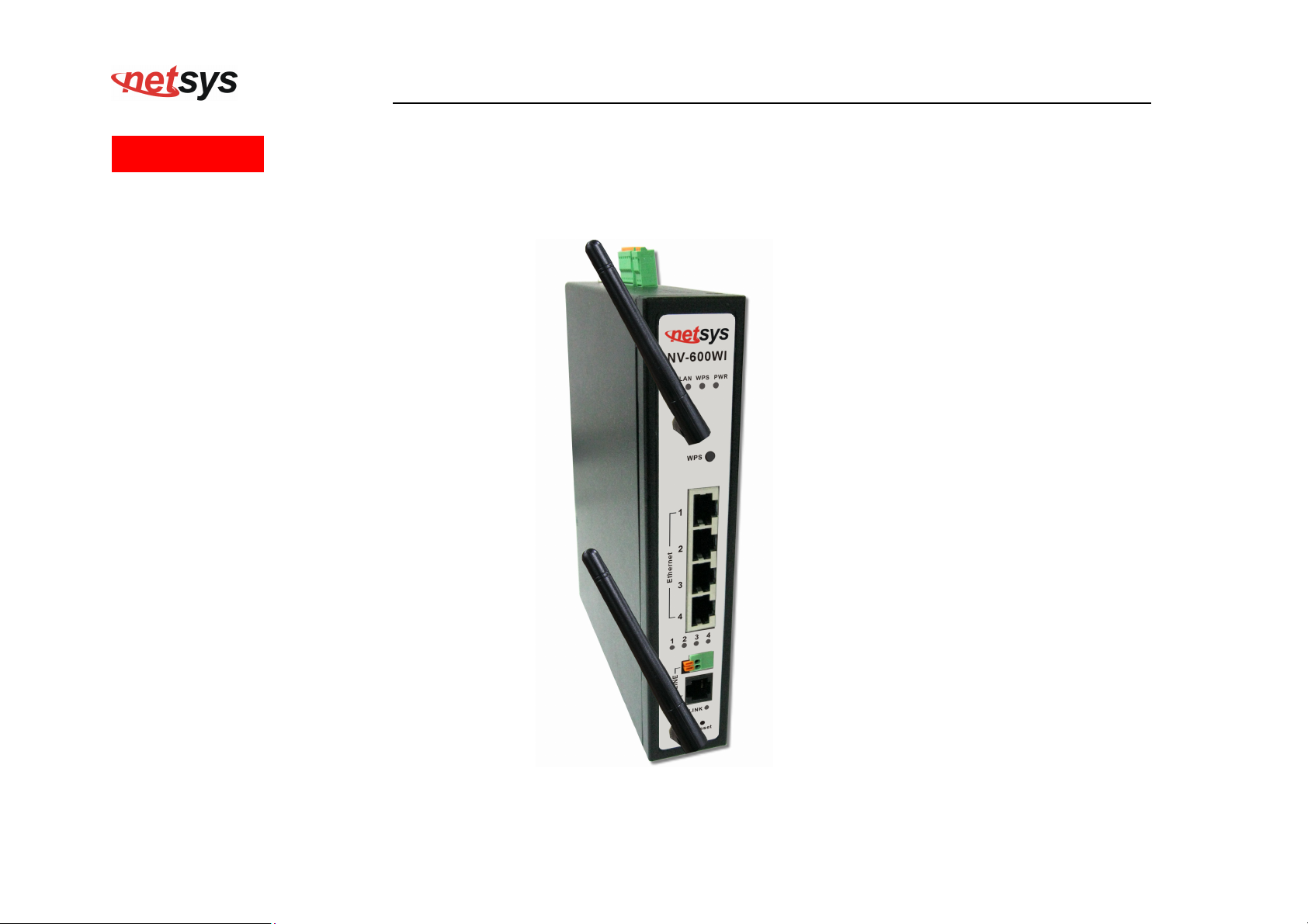
Chapter 3. Hardware Description
This section describes the important parts of the wireless VDSL2 router. It features the front and rear panel.
Wireless Router Outward
20
Page 22
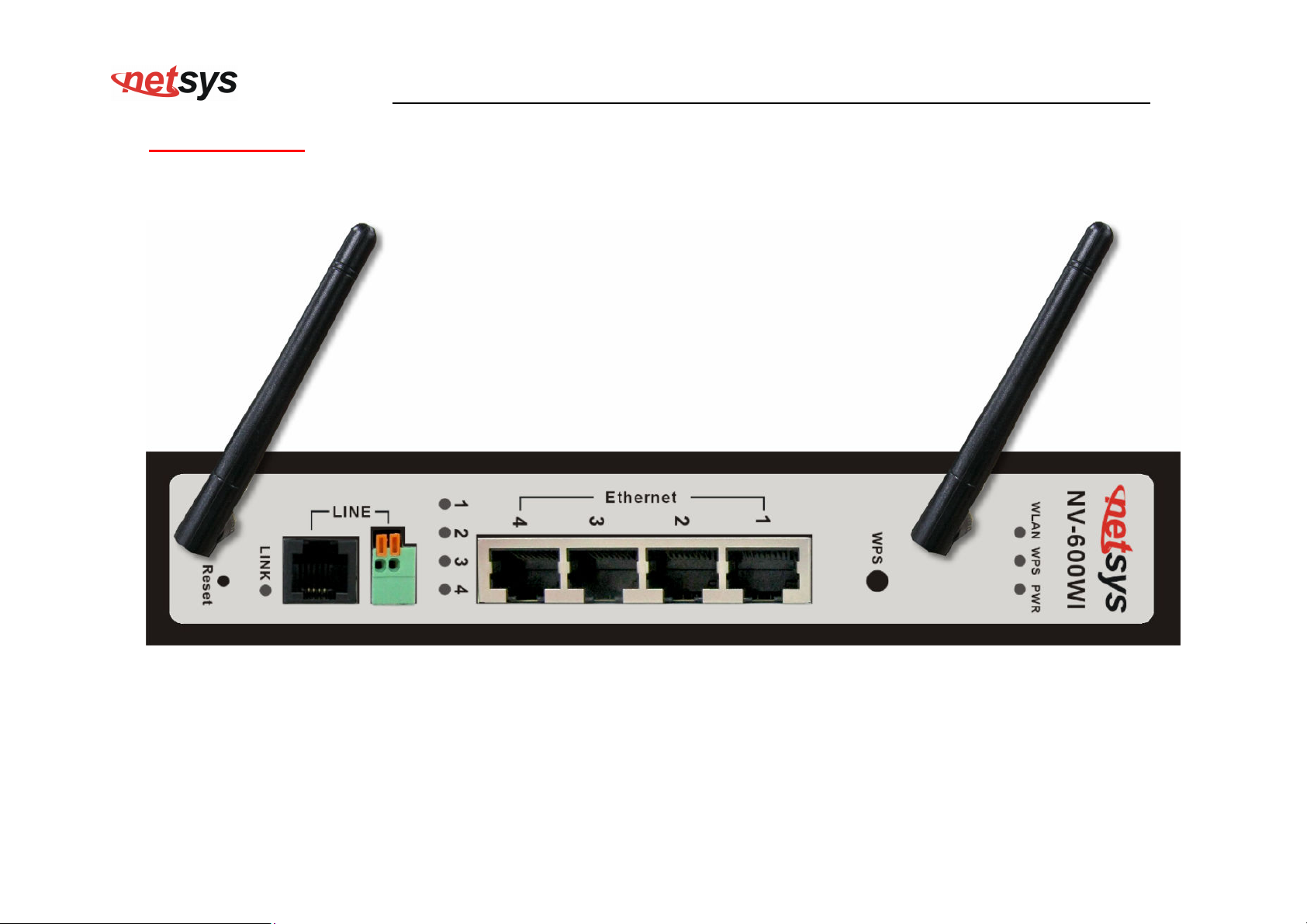
3.1 Front Panel
The front panel provides a simple interface monitoring of the router. (Figure 3.1) shows the front panel of the NV-600WI
NV-600WI Managed Industrial Grade Wireless VDSL2 Router USER’S MANUAL Ver. A2
Figure 3.1 NV-600WI Front panel
21
Page 23
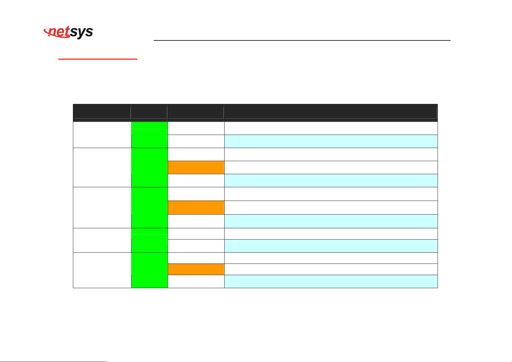
3.2 Front Indicators
The wireless router has Eight LED indicators. The following Table shows the description. (Table 3-1)
LED Color Status Descriptions
NV-600WI Managed Industrial Grade Wireless VDSL2 Router USER’S MANUAL Ver. A2
Table 3-1 LED Indicators Description and Operation
PWR
On(Steady) When the router is powered on, and in ready state.
Green
(Power LED)
Off When the router is powered off
On(Steady) The device has a good Ethernet connection.
E1 ~ E4
Green
Blinking
The device is sending or receiving data via the corresponding LAN port.
(Ethernet LED)
Off The LAN is not connected or has malfunctioned.
On(Steady) The Internet or network connection is up.
LINK
Green
Fast Blinking The device is sending or receiving data.
(VDSL2 LED)
Slow Blinking The Internet or network connection is down.
On(Steady) The WPS connection is ready.
WPS Green
Off The WPS is not available, or WPS is not enabled or initialized
On(Steady) Wireless access point is ready.
WLAN
Green
Blinking Data is being transmitted through WLAN
(Wireless LED)
Off Wireless access point is off or has malfunctioned.
22
Page 24
NV-600WI Managed Industrial Grade Wireless VDSL2 Router USER’S MANUAL Ver. A2
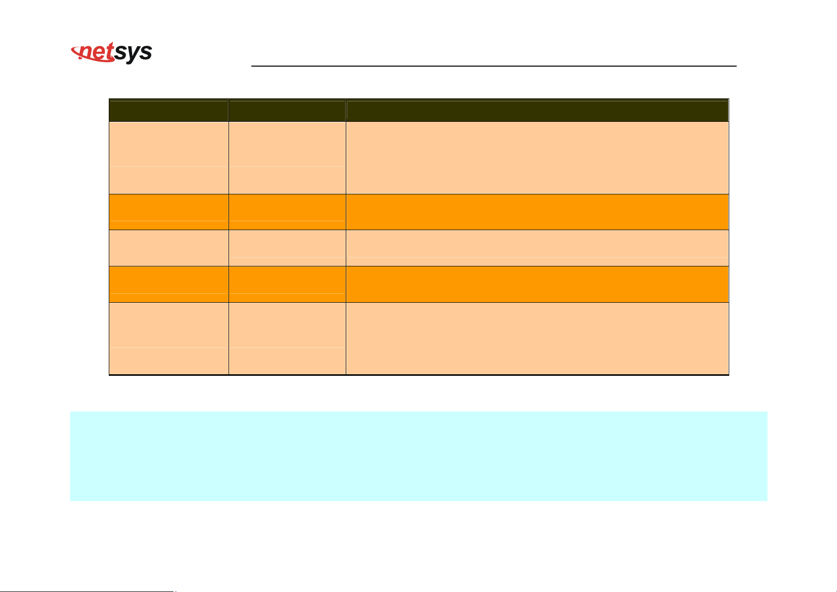
Table 3-2 Description of the router connectors
Connectors Type Description
The reset button allows users to reboot the VDSL2 or load the default
Reset Reset Button
settings.
Press and hold for 1-5 seconds: Reboot the VDSL2 Router
Press over 5 seconds: Load the default settings
For connecting to a VDSL2 device. (Do not use RJ11 and Terminal
Line RJ-11/Terminal Block
Block at the same time.)
Gigabit Ethernet
RJ-45 For connecting an Ethernet equipped device.
(E1-E4)
Allows data communication between the router and the VDSL2
Link (WAN) RJ-11/Terminal Block
network. (Do not use RJ11 and Terminal Block at the same time.)
Press this button to make a network connection through WPS (WPS
function is only supported on windows 7 or above operating systems).
WPS WPS Button
Every time the user presses the WPS button, there will be two minutes
of time to detect the available equipment.
Notes:
1. It is normal for the connection between two Routers to take up to 3 minutes, due to NV-600L/W to establish a link mechanism in
auto-negotiation, that detects and calculates CO and CPE both PBO and PSD level, noise levels and other arguments for getting
a better connection.
2. Every time the user presses the WPS button, there will be two minutes of time to detect the available equipment. If the WPS
function does not detect the device, the WPS light will turn off.
23
Page 25
NV-600WI Managed Industrial Grade Wireless VDSL2 Router USER’S MANUAL Ver. A2
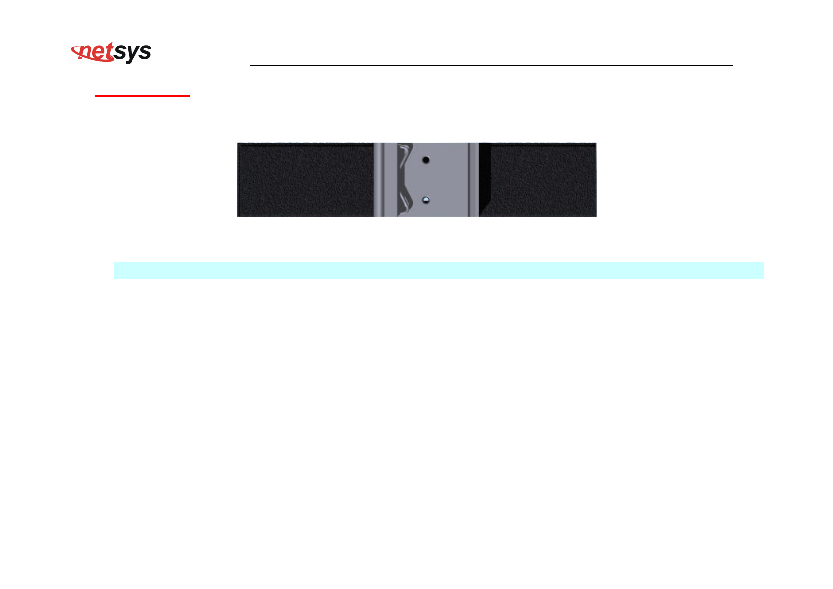
3.3 Rear Panel
The rear panel provides the din rail install hole. (Figure 3.2) shows the rear panel of the NV-600WI.
Figure 3.2 Rear Panel
Note:
Please refer to the section 2.6 to install DIN RAIL.
24
Page 26
NV-600WI Managed Industrial Grade Wireless VDSL2 Router USER’S MANUAL Ver. A2
3.4 Side Panel
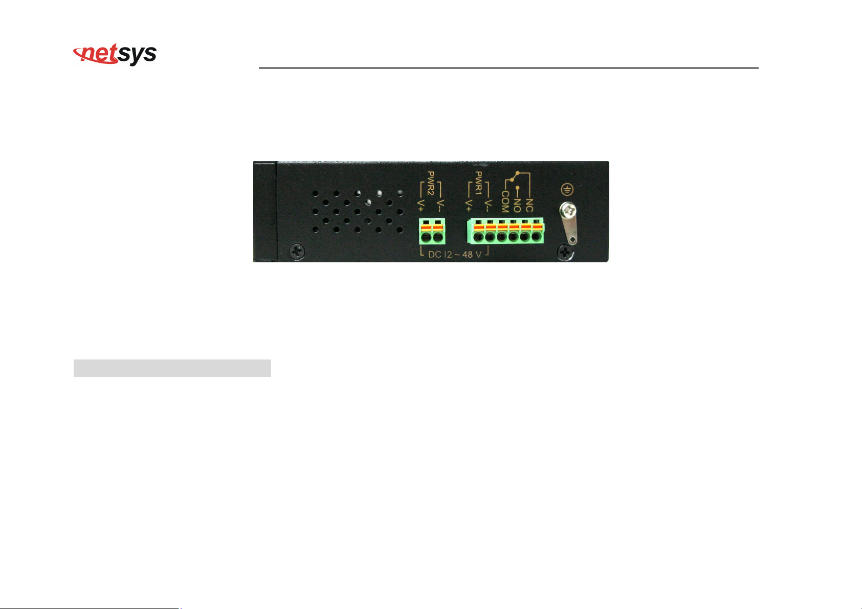
The following figure shows the side. (Figure 3.4)
Figure 3.4 Rear connectors
The following description introduces Dual power and Relay Contact.
Wiring the dual Power Inputs
The NV-600LI/WI has two sets of power inputs, power 1 and power 2, which are located on the NV-600WI’s side panel. Power 1 pins
are the bottom two contacts of the upper 6-contact terminal block and power 2 pins are the only two contacts on the lower 2-contact
terminal block.
25
Page 27
NV-600WI Managed Industrial Grade Wireless VDSL2 Router USER’S MANUAL Ver. A2
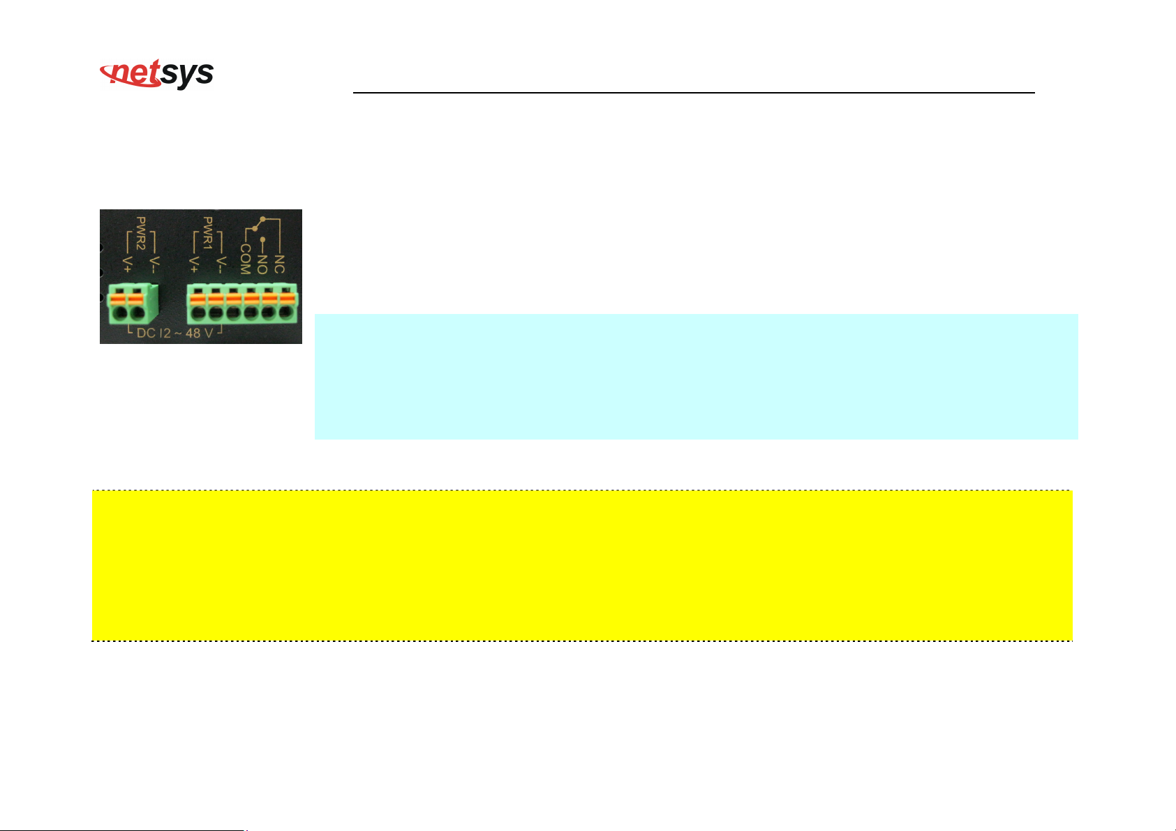
STEP 1: Insert the negative/positive DC wires into the V-/V+ terminals, respectively.
STEP 2: Place the DC wires into the terminal block connector: Push the orange switch of the terminal
block with a small flat-blade screwdriver, and then insert the DC wires into the holes below the orange
buttons, then release the small flat-blade screwdriver.
STEP 3: Insert the plastic terminal block connector prongs into the terminal block receptor, which is
located on the NV-600WI’s side panel.
Attention:
1. Please note that the negative DC wire must connect into the V- terminal, positive DC wire must
connect V+terminal. If contrary to the location of the wiring, NV-600WI will enable Reverse Polarity
Protection function automatically. DC power will not be able to directly through the machine.
2. Please note that if the DC power current exceeds 3A, NV-600WI will enable Overload Current
Protection function automatically. DC power will not be able to directly through the machine.
Safety Caution!
1. Be sure to disconnect the power when installing (uninstalling) the terminal block and power cables.
2. Please note that the user can use DC 12~48V dual power input (Redundant Power). Do not exceed DC 48V.
3. Be sure to disconnect the power before installing and/or wiring your NV-600WI router.
4. Please calculate the maximum possible current in each power wire and common wire. Observe all electrical codes
dictating the maximum current allowable for each wire size. If the current goes above the maximum ratings, the wiring
could overheat, causing serious damage to your equipment.
26
Page 28
NV-600WI Managed Industrial Grade Wireless VDSL2 Router USER’S MANUAL Ver. A2
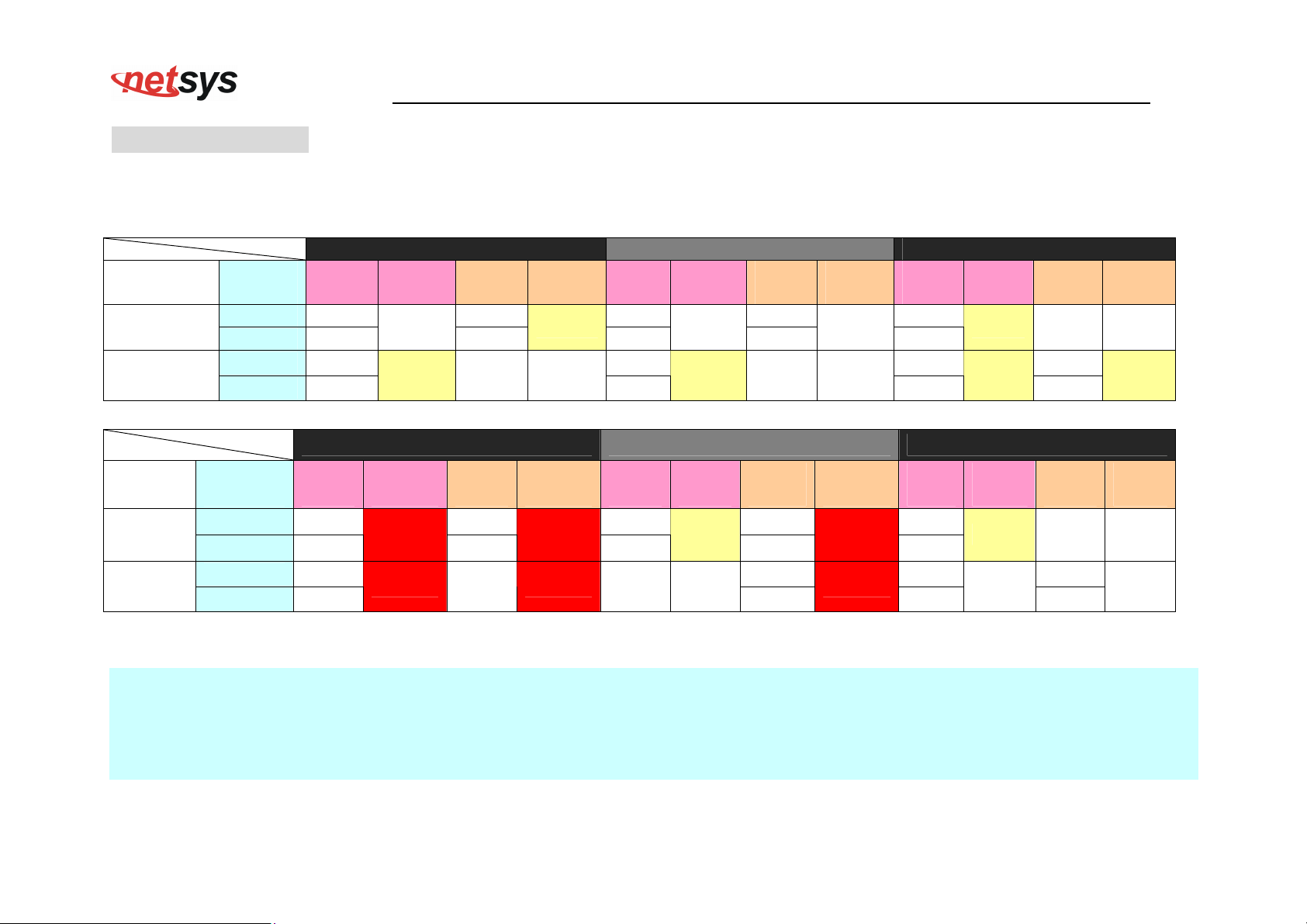
Power Input Status
The following Table shows the examples of the power input status. (Table 3-4)
Table 3-4
Example 1 Example 2 Example 3
Power
Item
Power 1
Power 2
Default
Polarity
–
+
–
+
Power
Input1
12V
–
12V
+
24V
–
24V
+
Output
State1
OFF
ON
Power
Input2
12V
–
12V
+
No
Power
Output
State2
ON
OFF
Power
Input1
12V
+
12V
–
24V
–
24V
+
Output
State1
Protection
ON
Example 4 Example 5 Example 6
Power
Input2
12V
+
12V
–
No
Power
Output
State2
Protection
OFF
Power
Input1
48V
–
48V
+
48V
–
48V
+
Output
State1
ON
ON
Power
Input2
No
Power
48V
–
48V
+
Output
State2
OFF
ON
Power
Item
Power 1
Power 2
Default
Polarity
–
+
–
+
Power
Input1
12V
–
12V
+
60V
–
60V
+
Output
State1
Malfunction
Malfunction
Power
Input2
12V
–
12V
+
No
Power
Output
State2
Malfunction
Malfunction
Power
Input1
12V
–
12V
+
No
Power
Output
State1
ON
OFF
Power
Input2
Output
State2
Power
Input1
12V– 48V
12V+
60V– 48V
60V+
Malfunction
48V
Malfunction
48V
–
+
+
–
Output
State1
ON
Protection
Power
Input2
No
Power
48V
+
48V
–
Output
State2
OFF
Protection
Notes:
1. State 1 always happens before State 2.
2. Protection means enable Reverse Polarity Protection function.
3. Please note that if use different DC voltage, higher voltage will feeding to NV-600LI or NV-600WI.
4. Please note that the warranty is void if DC 48V power input is exceeded.
27
Page 29
NV-600WI Managed Industrial Grade Wireless VDSL2 Router USER’S MANUAL Ver. A2
Wiring the Relay Contact
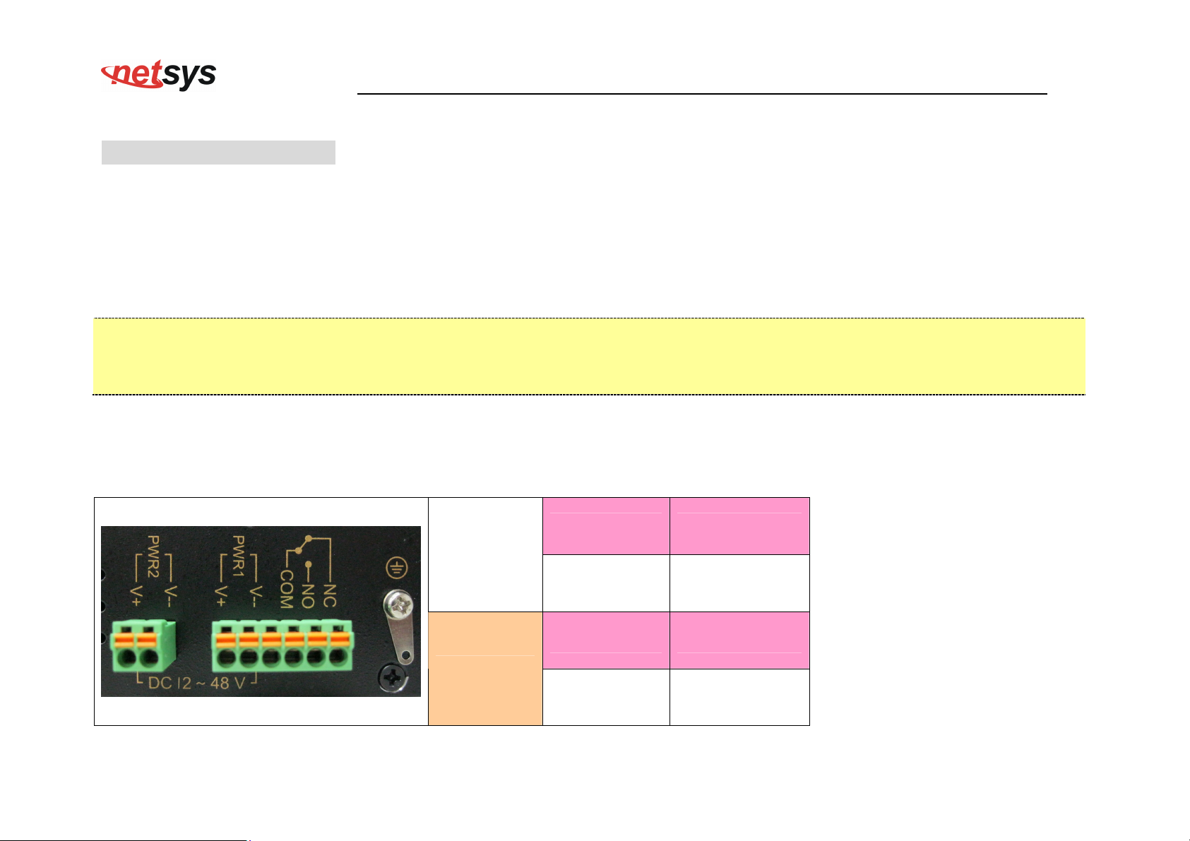
The NV-600WI has a set of relay outputs. The relay contact uses two of the terminal block’s contacts located on the NV-600WI’s side
panel. Refer to the following table showing how to connect the wires to the terminal block connector. In this section, we illustrate the
meaning of the two contacts used to connect the relay contact.
Fault Tip:
The relay contacts of the 6-pin terminal block connector are used to detect user-configured events. The three wires attached to the
fault contacts form an open circuit when a user-configured event is triggered. If a user-configured event does not occur, the fault
circuit remains closed. The relay output has current carrying capacity of 1 A @ 24 VDC.
The following Table shows the Relay circuit and power status. (Table 3-5)
Table 3-5 Relay Circuit Status and Power ON/OFF Status.
COM & NC Open Circuit
Power ON
COM & NO Short Circuit
COM & NC Short Circuit
Power OFF
COM & NO Open Circuit
28
Page 30
Grounding the NV-600WI
NV-600WI is designed to enhance EMS performance by grounding. NV-600WI comes with metal DIN-Rail brackets for grounding the
switches. For optimal EMS performance, connect the ground lug at the right of the NV-600WI side panel to the grounding point.
NV-600WI Managed Industrial Grade Wireless VDSL2 Router USER’S MANUAL Ver. A2
Before installing and powering the device, please read and follow these essentials:
Use separate paths to route wiring for power and devices. If power wiring and device wiring paths must cross make sure the
wires are perpendicular at the intersection point.
Note:
Do not run signal or communications wiring and power wiring through the same wire conduit. To avoid interference, wires with
different signal characteristics should be routed separately.
You can use the type of signal transmitted through a wire to determine which wires should be kept separate. The rule of thumb
is that wiring sharing similar electrical characteristics can be bundled together.
You should separate input wiring from output wiring.
We recommend that you mark all equipment in the wiring system.
29
Page 31
NV-600WI Managed Industrial Grade Wireless VDSL2 Router USER’S MANUAL Ver. A2
Chapter 4.
The NV-600WI provides a built-in HTML based management interface that allows configuration of the NV-600WI via
Internet Browser. Best viewed using Chrome or Firefox browsers.
In order to use the web browser to configure the device, you may need to allow:
Launch your web browser and input the IP address 192.168.1.1 (NV-600WI) in the Web page.
The default username and password can be found in the following section.
Configuring the NV-600WI via Web Browser
• Web browser pop-up windows from your device. Web pop-up blocking is enabled by default in windows XP
SP2 or above.
• Java Scripts. (Enabled by default)
• Java permissions. (Enabled by default)
30
Page 32
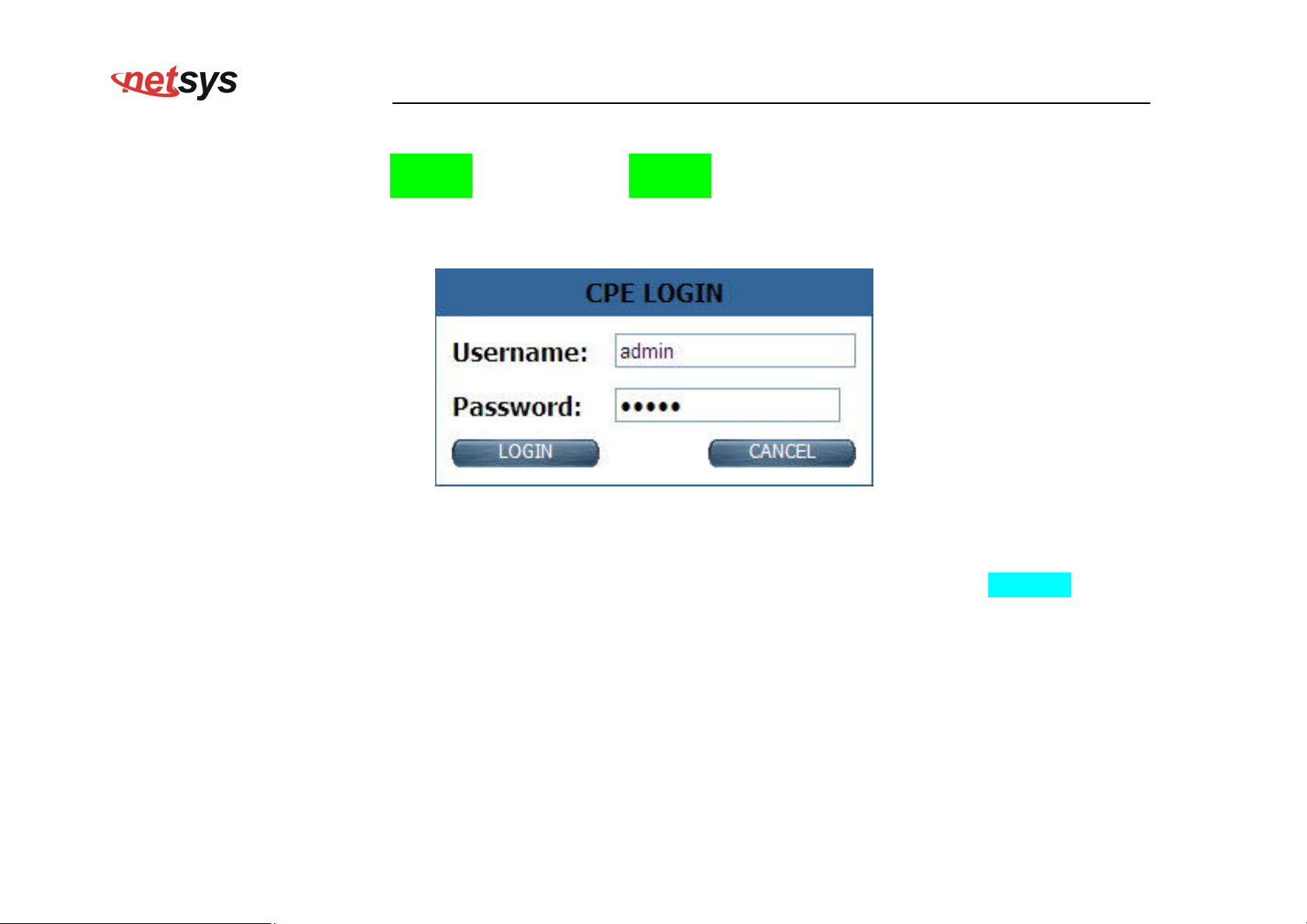
4.1 Login
The default username is “admin“ and password is “admin“, too. The password is changeable in Administrator
Settings. It is advisable to change the administrator password for the security of your network.
NV-600WI Managed Industrial Grade Wireless VDSL2 Router USER’S MANUAL Ver. A2
Figure 4.1 Login Password
About Wifi mode:
Default wifi mode is enabled, default security setting is WPA2-AES, and the shared key (password) is “12345678”. User can find
information on wifi and login information sticker; it is located at the bottom of the product.
31
Page 33
NV-600WI Managed Industrial Grade Wireless VDSL2 Router USER’S MANUAL Ver. A2
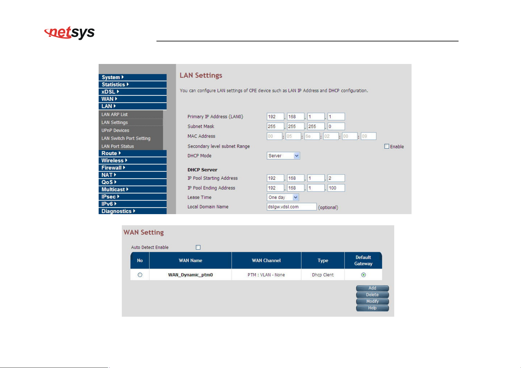
The NV-600WI default mode is Router mode. The following screenshots show default LAN and WAN settings.
32
Page 34
NV-600WI Managed Industrial Grade Wireless VDSL2 Router USER’S MANUAL Ver. A2
4.1.1 Home
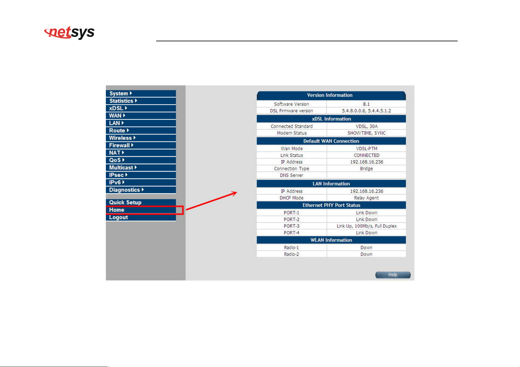
After logging in successfully using the username admin, the home page of NV-600WI is loaded in the web browser. The user can
also click “Home” on the left navigation bar. The home page displays the information screen as shown in Figure 4.1.1
Figure 4.1.1 Home Information
The screen contains the following details:
33
Page 35
NV-600WI Managed Industrial Grade Wireless VDSL2 Router USER’S MANUAL Ver. A2
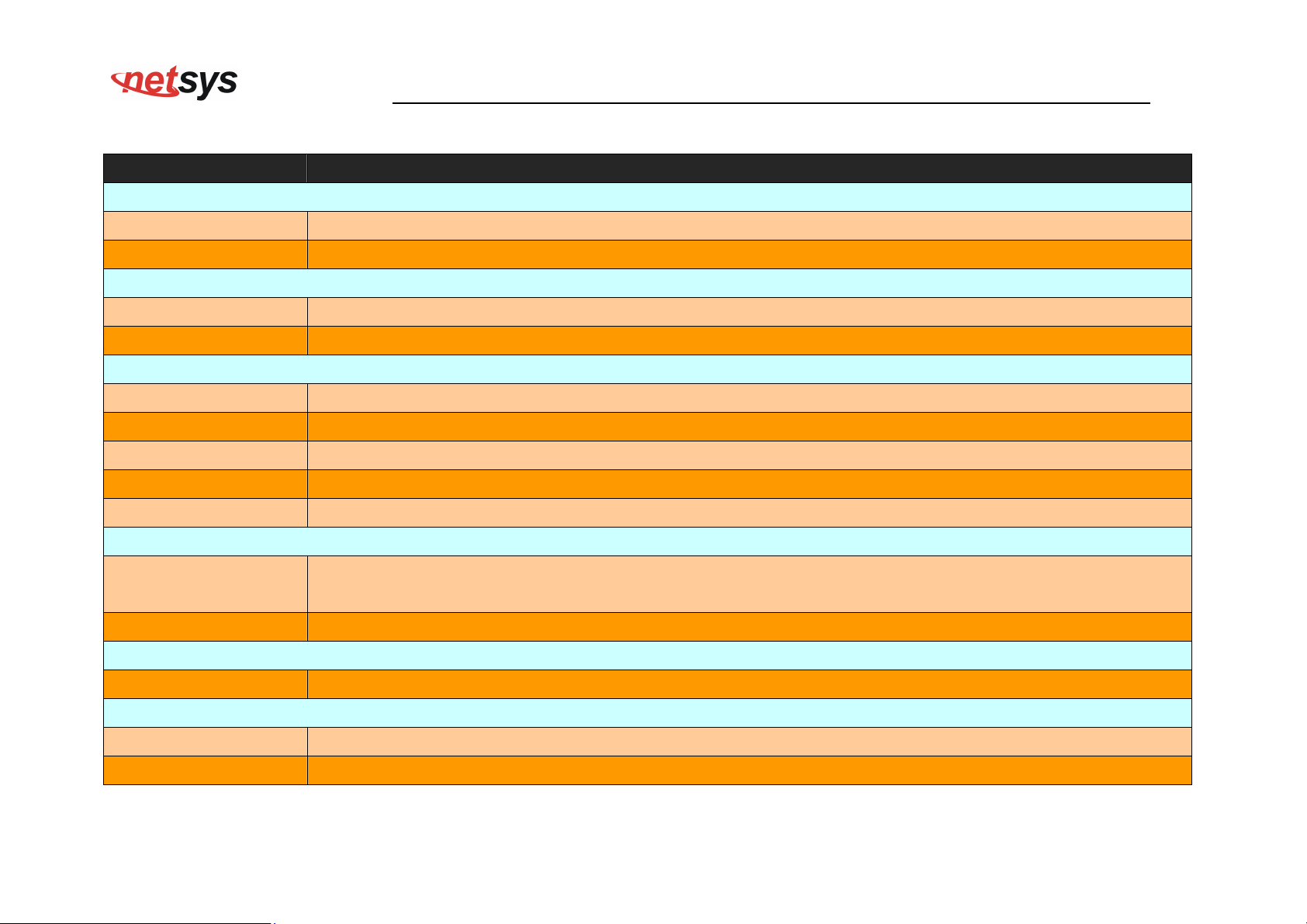
Fields in Home page
Field Description
Version Information
Software Version Shows the current version of the Software loaded on the device.
DSL Firmware version Shows the current version of xDSL firmware loaded on the device. Applicable only for DSL platforms.
xDSL Information
Connected Standard The DSL Standard which is being used currently between DSL CPE and DSLAM.
Modem Status Displays the status of the physical xDSL Line in terms of the modem and mode selected.
Default WAN Connection
Wan Mode Current WAN mode being used in CPE.
Link Status Shows the status of default WAN connection.
IP Address Shows the IP address of default WAN connection.
Connection Type Shows the Connection Type information of default WAN connection.
DNS Server Shows the primary and secondary DNS servers configured in default WAN connection.
LAN information
IP Address
Shows the IP address of LAN interface of CPE. This IP address to be used for accessing the CPE device
from LAN side e.g. Web UI, TELNET or UPnP sessions.
DHCP Mode Shows the DHCP Mode on LAN interface of CPE device.
Ethernet PHY Port Status
PORT-1 ~PORT-4 Shows the status of first to fourth Ethernet port of CPE device.
WLAN Information
Radio-1 Shows the status of WLAN Radio-1.
Radio-2 Shows the status of WLAN Radio-2. (Available only in concurrent dual band WLAN platforms).
34
Page 36
NV-600WI Managed Industrial Grade Wireless VDSL2 Router USER’S MANUAL Ver. A2
4.1.2 Quick Setup
The Quick Setup is located on the left side of the screen. Quick Setup provides a simple and easy step for applying minimal
configuration to CPE device, for making it ready to use. The CPE Quick Setup window is displayed as shown in Figure 4.1.2.
Click on Quick Setup to view and configure the following connections.
Figure 4.1.2 Quick Setup
WAN Setup
When the user clicks on Quick Setup, the WAN Setup tab is displayed as shown in Figure 4.1.2.1. The WAN Setup enables the user
to configure the default WAN connection. The user has to supply fields and the CPE device will take all necessary actions to ensure
the default WAN is configured. In case, the WAN connection already exists in CPE device, the same gets re-created with newly
supplied attributes from the user. The default WAN Setup configuration shows the Bridged status.
35
Page 37
NV-600WI Managed Industrial Grade Wireless VDSL2 Router USER’S MANUAL Ver. A2
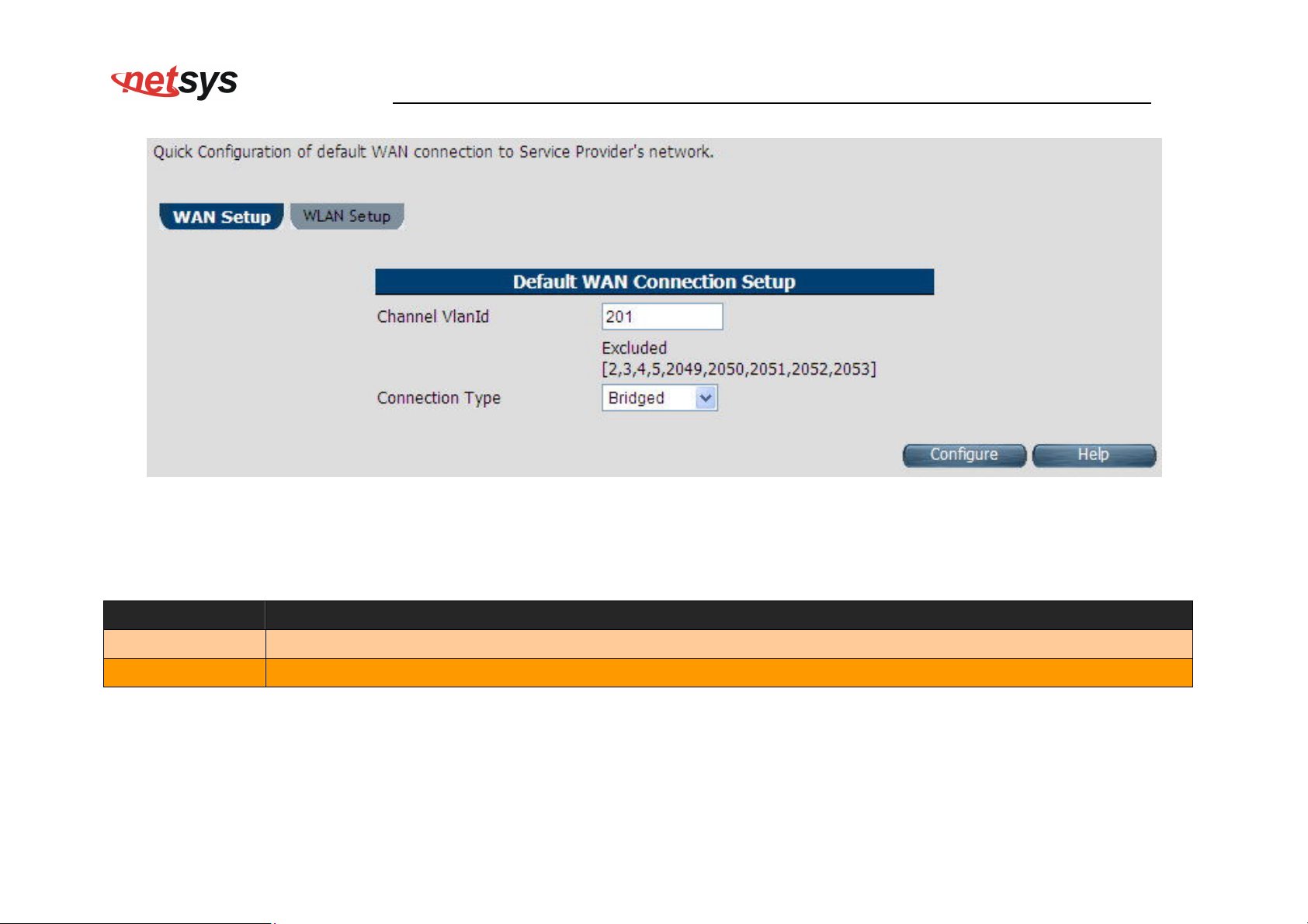
The screen contains the following details:
Figure 4.1.2.1 WAN setup Bridged
Fields in Home page
Field Description
Channel VlanId Specify VLAN Id. Reserved or internally used VLANs that cannot be configured in Quick WAN Setup are listed.
Connection Type
Specify the Connection Type from the dropdown. Available options are Bridged, Dynamic and Static.
Click Configure to configure the default WAN connection setup.
36
Page 38
NV-600WI Managed Industrial Grade Wireless VDSL2 Router USER’S MANUAL Ver. A2
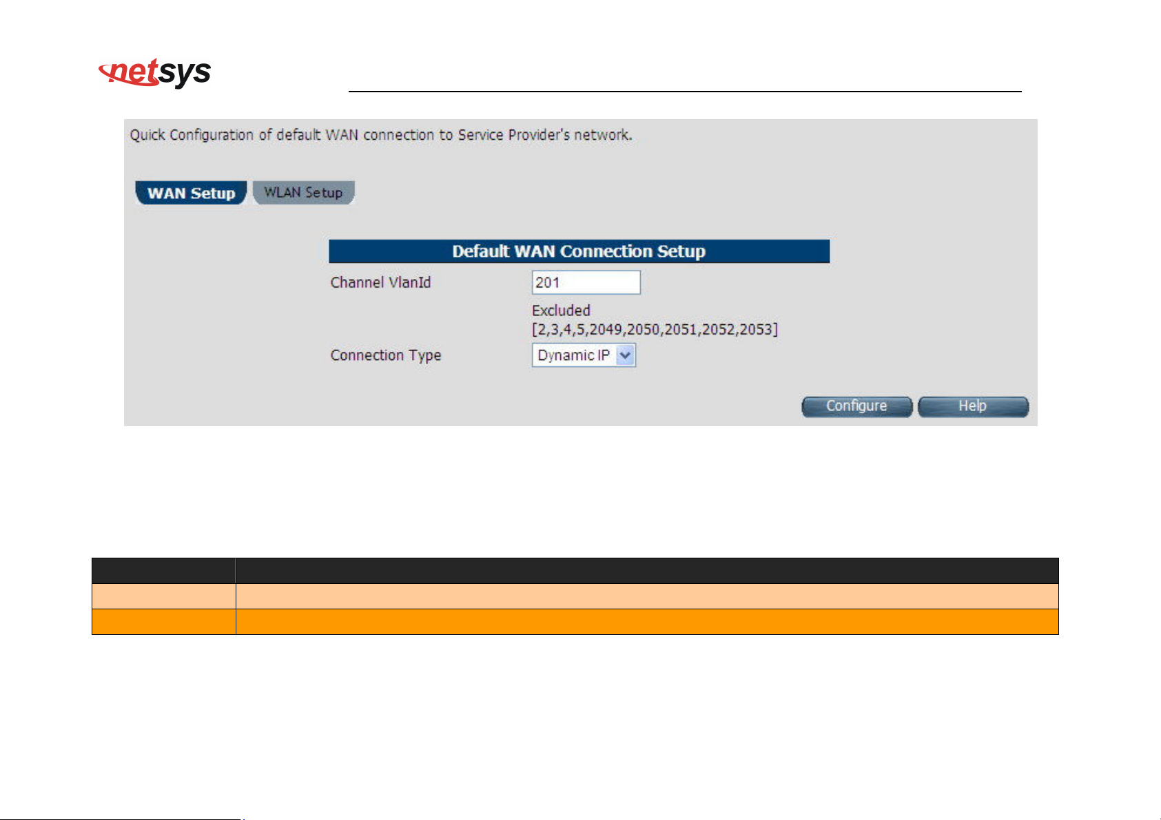
Figure 4.1.2.2 WAN setup Dynamic IP
The screen contains the following details:
Fields in WAN setup Dynamic IP
Field Description
Channel VlanId Specify VLAN Id.
Connection Type Specify the Connection Type from the dropdown.
Click Configure to configure the selected WAN connection setup.
37
Page 39
NV-600WI Managed Industrial Grade Wireless VDSL2 Router USER’S MANUAL Ver. A2
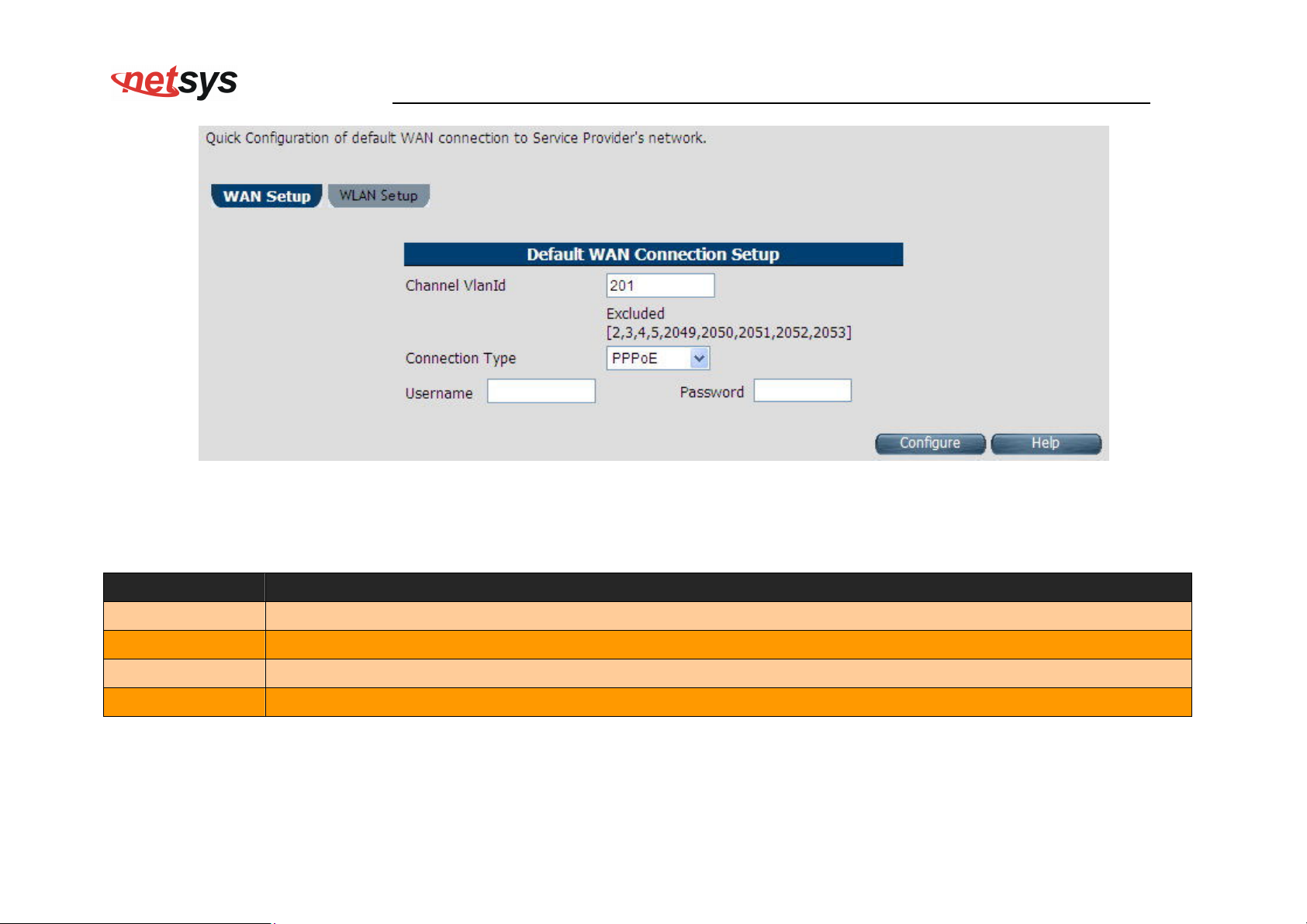
The screen contains the following details:
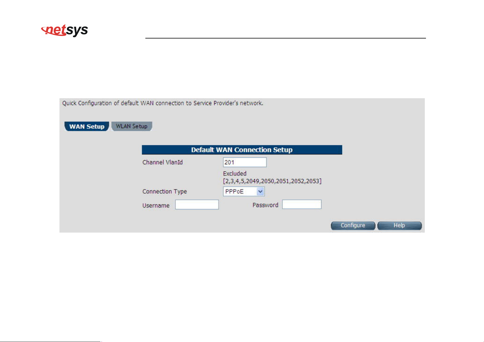
Figure 4.1.2.3 WAN setup PPPoE
Fields in WAN setup PPPoE
Field Description
Channel VlanId Specify VLAN Id.
Connection Type Specify the Connection Type from the dropdown.
Username Enter a valid Username.
Password Enter a valid Password.
Click Configure to configure the selected WAN connection setup.
38
Page 40
NV-600WI Managed Industrial Grade Wireless VDSL2 Router USER’S MANUAL Ver. A2
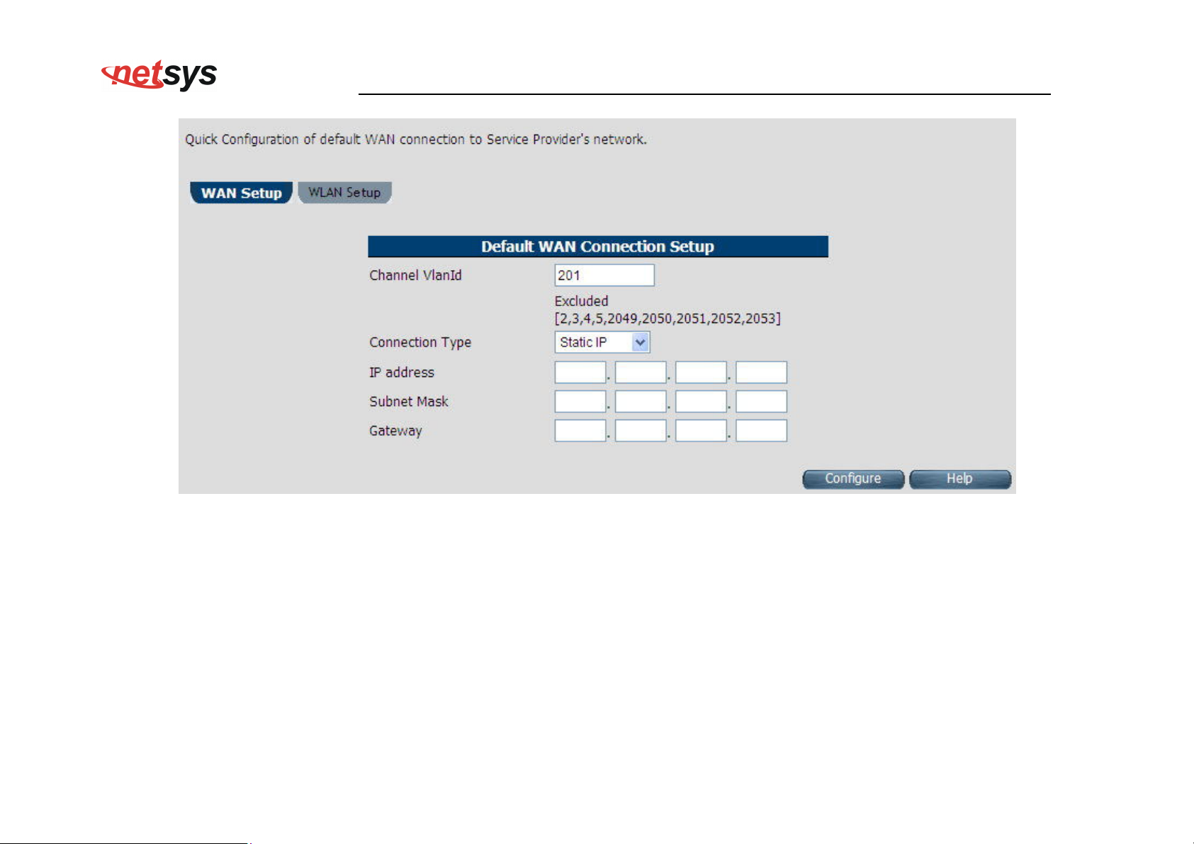
Figure 4.1.2.4 WAN setup Static IP
The screen contains the following details:
39
Page 41
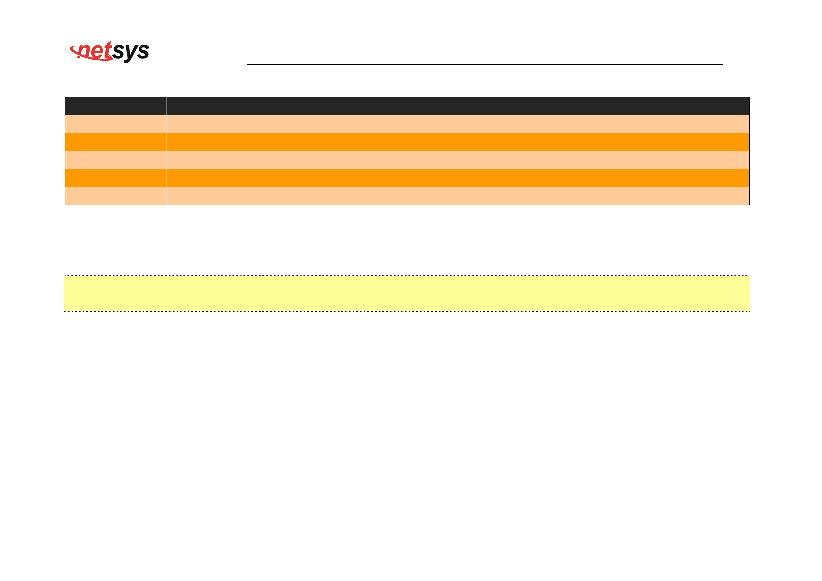
Fields in WAN setup Static IP
Field Description
Channel VlanId Specify VLAN ID.
Connection Type Specify the Connection Type from the dropdown.
IP Address Specify the IP Address of NV-600WI CPE’s WAN link.
Subnet Mask Specify the Subnet Mask of NV-600WI CPE’s WAN link.
Gateway Specify the Gateway address of the NV-600WI CPE’s WAN.
Click Configure to configure the selected WAN connection setup.
Note:
When WAN mode is other than ATM, the corresponding web pages will be available in WAN setup. Those web pages will not ask
the user for fields like ATM VCC etc.
NV-600WI Managed Industrial Grade Wireless VDSL2 Router USER’S MANUAL Ver. A2
40
Page 42
NV-600WI Managed Industrial Grade Wireless VDSL2 Router USER’S MANUAL Ver. A2
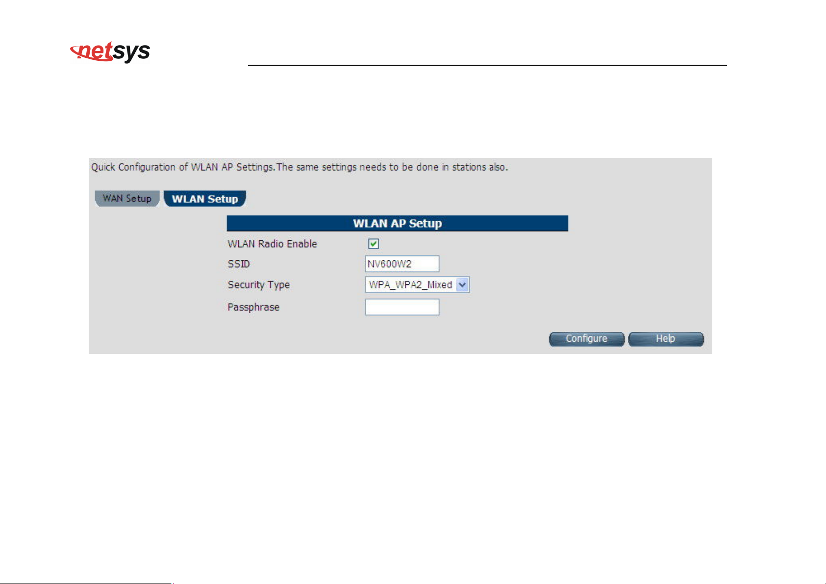
WLAN Setup
When the user clicks on Quick Setup, the WLAN Setup tab is displayed as shown in Figure 4.1.2.5. The WLAN tab allows the
user to configure the Wireless LAN in CPE Router.
Figure 4.1.2.5 WLAN Setup
41
Page 43
NV-600WI Managed Industrial Grade Wireless VDSL2 Router USER’S MANUAL Ver. A2
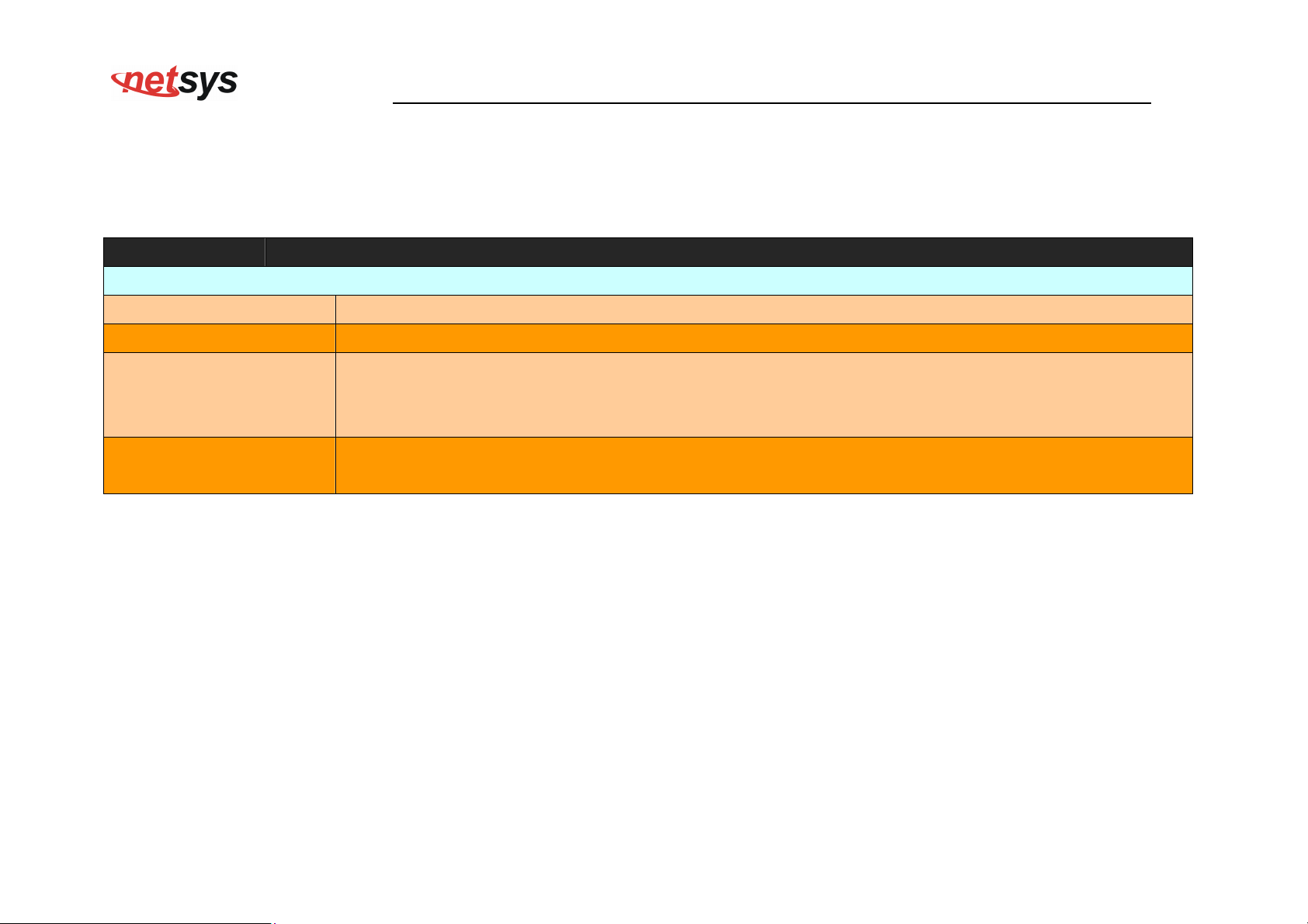
The screen contains the following details:
Fields in WAN setup Static IP
Field Description
WLAN AP Setup
WLAN Radio Enable To Enable or Disable WLAN feature in CPE.
SSID SSID Name.
Security Type for AP are:
Security Type
Basic (non-11n mode)
WPA (non-11n mode)
Secret String, from where the dynamic keys are generated. It is applicable only in case of WPA2 or
Passphrase
WPA-WPA2 Mixed mode in Security Type.
Click Configure to configure the Wireless LAN AP in CPE device.
42
Page 44
4.2 Select the Menu Level
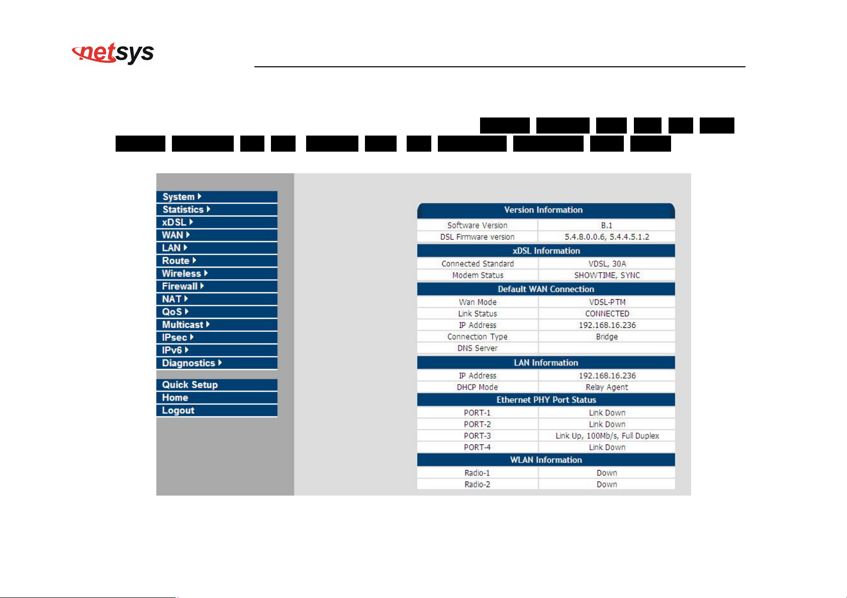
There is an easy Setup for end users at the setup of NV-600WI with SYSTEM, Statistics, xDSL, WAN, LAN, Route,
Wireless, FIREWALL, NAT, QoS , Multicast, IPsec , IPv6, Diagnostics, Quick Setup, Home, Logout for more
detailed configurations.
NV-600WI Managed Industrial Grade Wireless VDSL2 Router USER’S MANUAL Ver. A2
Figure 4.2 Select the Menu Level (NV-600WI)
43
Page 45
4.3 Select “SYSTEM”
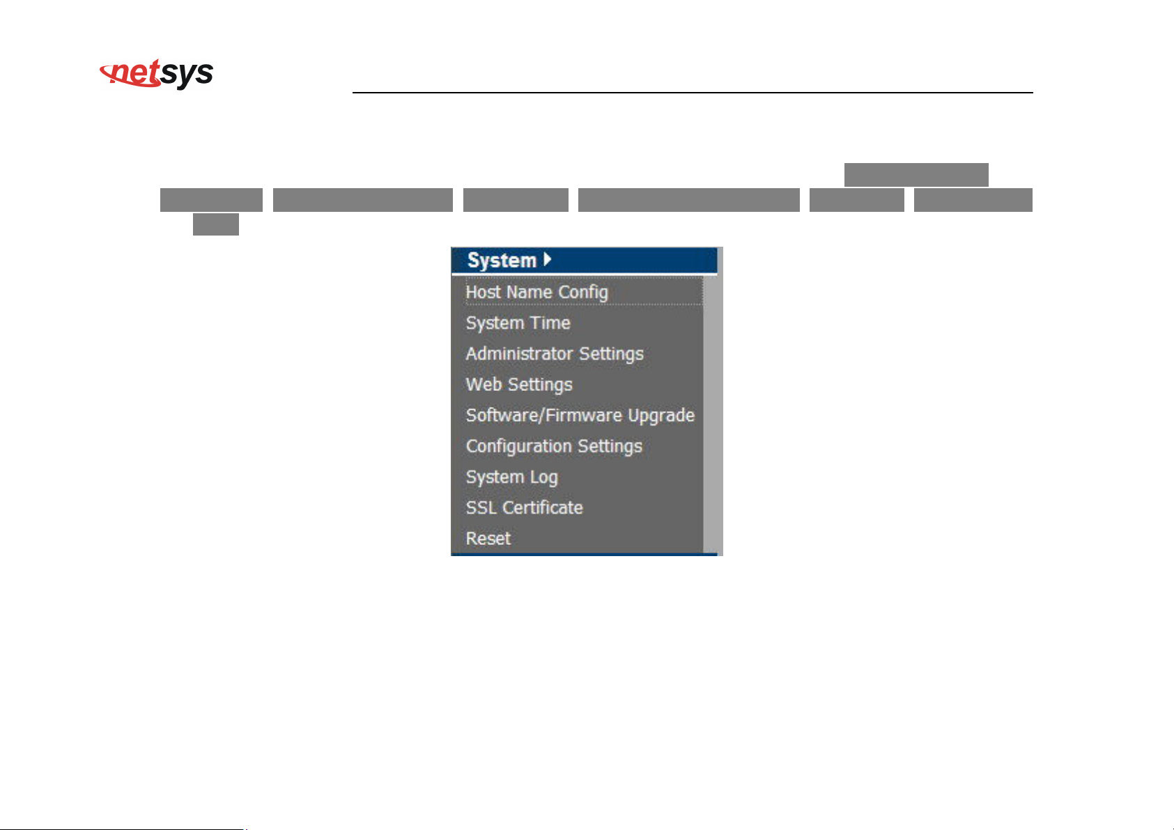
Select the “SYSTEM”. The menu below will be used frequently. It includes the sub-menus of Host Name Config、
System Time、Administrator Settings、Web Settings、Software/Firmware Upgrade、System Log、SSL Certificate
and Reset. A screen is displayed as shown in Figure 4.3
NV-600WI Managed Industrial Grade Wireless VDSL2 Router USER’S MANUAL Ver. A2
Figure 4.3 System Setup
44
Page 46
NV-600WI Managed Industrial Grade Wireless VDSL2 Router USER’S MANUAL Ver. A2
4.3.1 Host Name Configuration
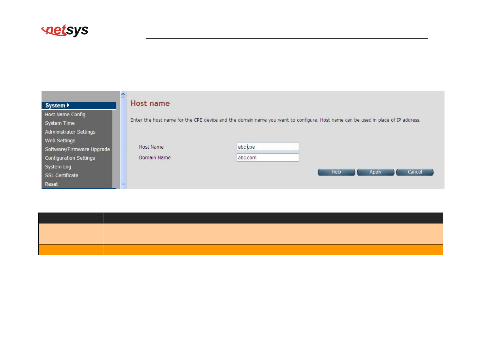
To configure the host name of NV-600WI, you have to enter host and domain name. Click the Host Name Config link (System >
Host Name Config) on the left navigation bar. A screen is displayed as shown in Figure 4.3.1.
Figure 4.3.1 Host Name Configuration
Fields in Host Name Configuration
Field Description
Enter the host name of the VDSL2 CPE. This is used to address VDSL2 CPE, by using this name instead of
Host Name
typing the IP address. Maximum Characters: 60.
Domain Name Enter the domain name of the VDSL2 CPE. Maximum Characters: 60.
Click Apply at any time during configuration to save the information that you have entered.
Click Cancel to exit from this page without saving the changes.
45
Page 47
NV-600WI Managed Industrial Grade Wireless VDSL2 Router USER’S MANUAL Ver. A2
4.3.2 System Time
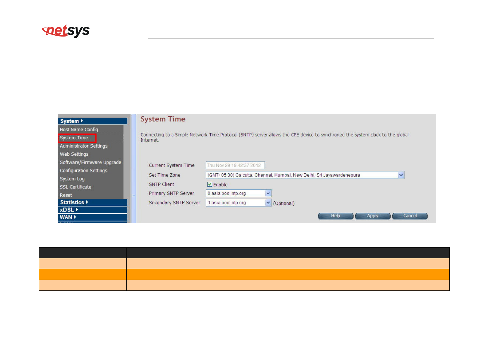
You can set System Time by connecting to a Simple Network Time Protocol (SNTP) server allows the Modem to synchronize the
system clock to the global Internet. The synchronized clock in the Modem is used to record the security log and control client filtering.
This page provides the time zone selection and NTP (Network Time Protocol) configuration. Click the System Time link (System >
System Time) on the left navigation bar and a screen is displayed as shown in Figure 4.3.2.
Figure 4.3.2 System Time Configuration
Fields in System Time
Field Description
Current System Time Current Time in System shown in Day, Date and Time of day.
Set Time Zone Select the time zone form the list of worldwide time zones in pull-down options.
SNTP Client Tick on Check box, if SNTP client has to be enabled.
46
Page 48
NV-600WI Managed Industrial Grade Wireless VDSL2 Router USER’S MANUAL Ver. A2
Fields in System Time (Cont’d)
Field Description
Primary SNTP Server Main NTP Server to be selected form dropdown list.
Secondary SNTP Server Backup NTP Server (optional).
Click Apply at any time during configuration to save the information that you have entered.
Click Cancel to exit from this page without saving the changes.
Note:
Static Routing functionality is used to define the connected Gateway between the LAN and WAN. For example, if we want
to activate the Network Time Protocol (NTP) service, we have to define the Gateway connected to NTP server in the WAN.
Please refer to “static routing” for your reference.
47
Page 49
NV-600WI Managed Industrial Grade Wireless VDSL2 Router USER’S MANUAL Ver. A2
4.3.3 Administrator Settings (User Account Management)
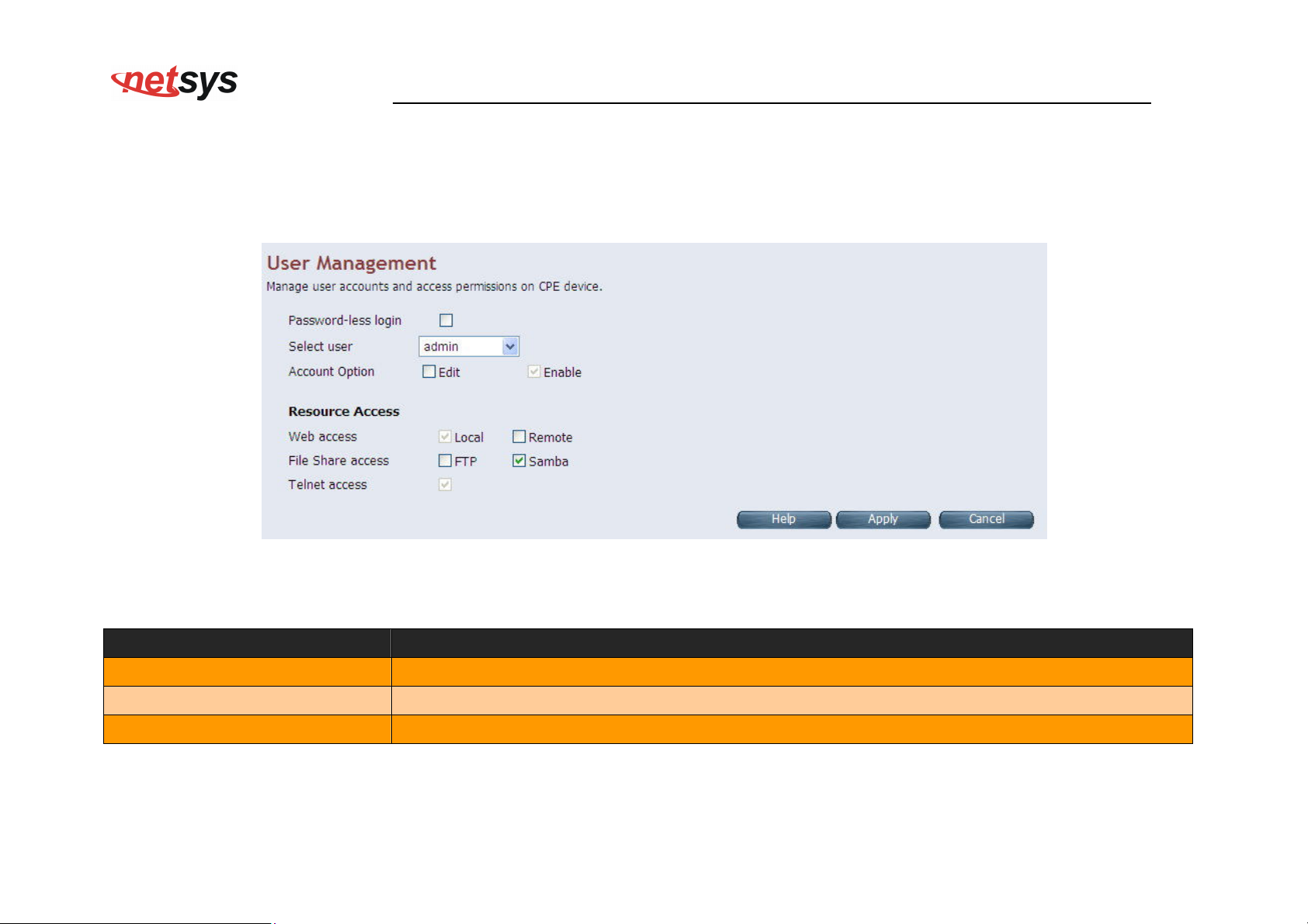
If you want to change the password for the administrator, click the Administrator Settings link (System > Administrator Settings)
in the left navigation bar. A screen is displayed as shown in Figure 4.3.3. This page allows the user to change the login password.
Figure 4.3.3 Administrator Settings
Fields in Administrator Settings
Field Description
Password-less Login Select this to enable login without prompting for Login page.
Select User Select user type. The available options are admin and support_user.
Account Option Edit option to modify User settings or Enable checkbox to Enable/Disable User.
48
Page 50
Fields in Resource Access
Field Description
Web Access Web UI access permission - Local, Remote or both.
File Share Access File share Access Permission - FTP, Samba or both.
Telnet Access Telnet console access for user.
NV-600WI Managed Industrial Grade Wireless VDSL2 Router USER’S MANUAL Ver. A2
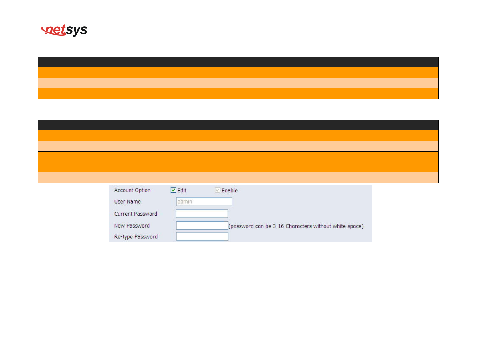
Fields in Account Option (Selected Edit boxes)
Field Description
User Name Type a new user name of account.
Current Password The user should specify the current login password.
New Password
Re-type Password The user should re-type the new password entered in previous field.
The user should specify the new password desired. The password should be at least
3 characters and not more than 16 characters in length without a white space.
Figure 4.3.3-1
Click Apply at any time during configuration to save the information that you have entered.
Click Cancel to exit from this page without saving the changes.
49
Page 51
NV-600WI Managed Industrial Grade Wireless VDSL2 Router USER’S MANUAL Ver. A2
4.3.4 Web Settings
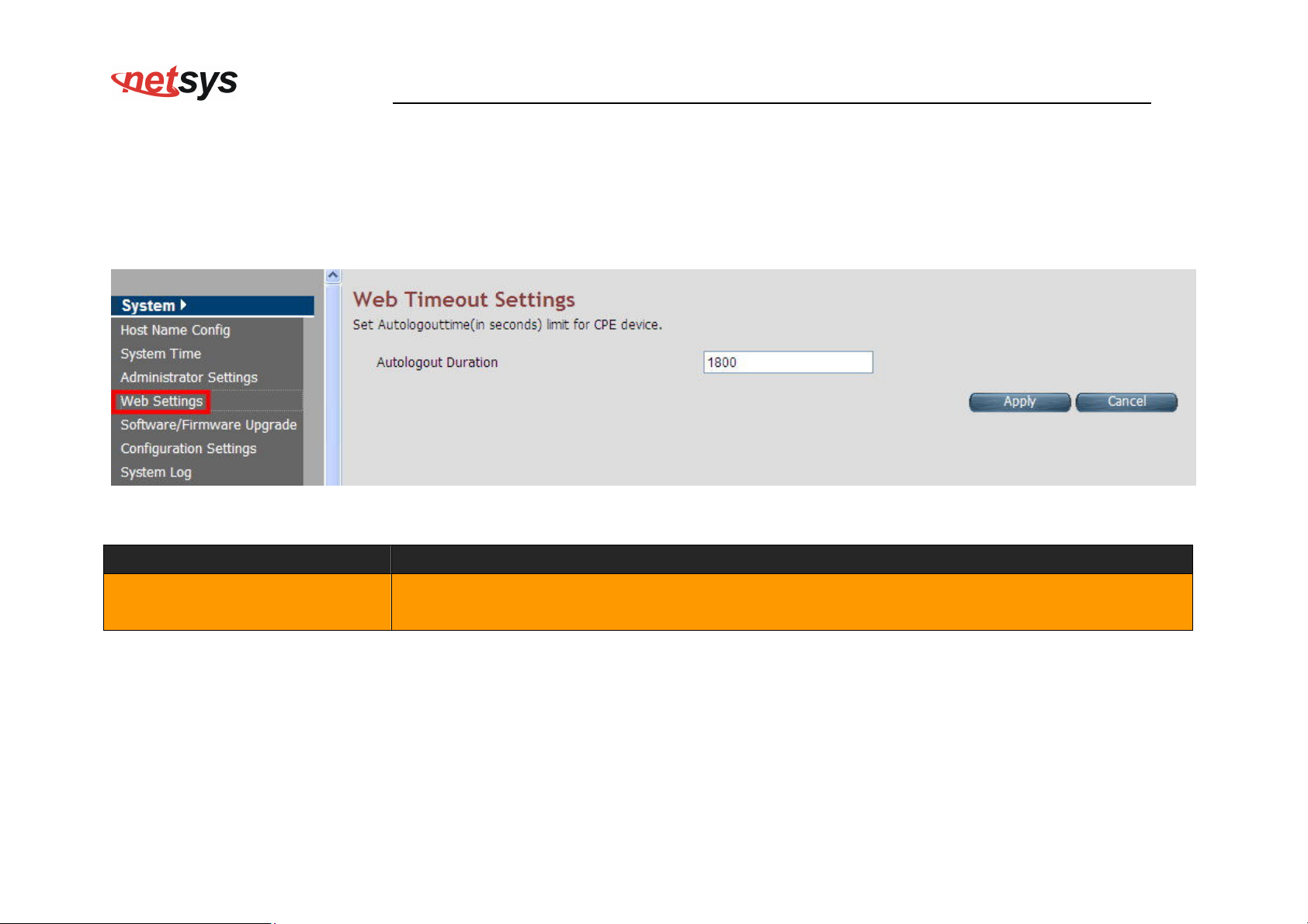
This page shows the details of Web login timeout settings for the CPE device in seconds. Click the Web Settings link (System >
Web Settings) on the left navigation bar and a screen is displayed as shown in Figure 4.3.4
Figure 4.3.4 Web Settings
Fields in Web Settings
Field Description
This is logout duration after which the web session is automatically log-out. The unit is in
Auto logout Duration
seconds.
Click Apply at any time during configuration to save the information that you have entered.
Click Cancel to exit from this page without saving the changes.
50
Page 52
NV-600WI Managed Industrial Grade Wireless VDSL2 Router USER’S MANUAL Ver. A2
4.3.5 Software/Firmware Upgrade
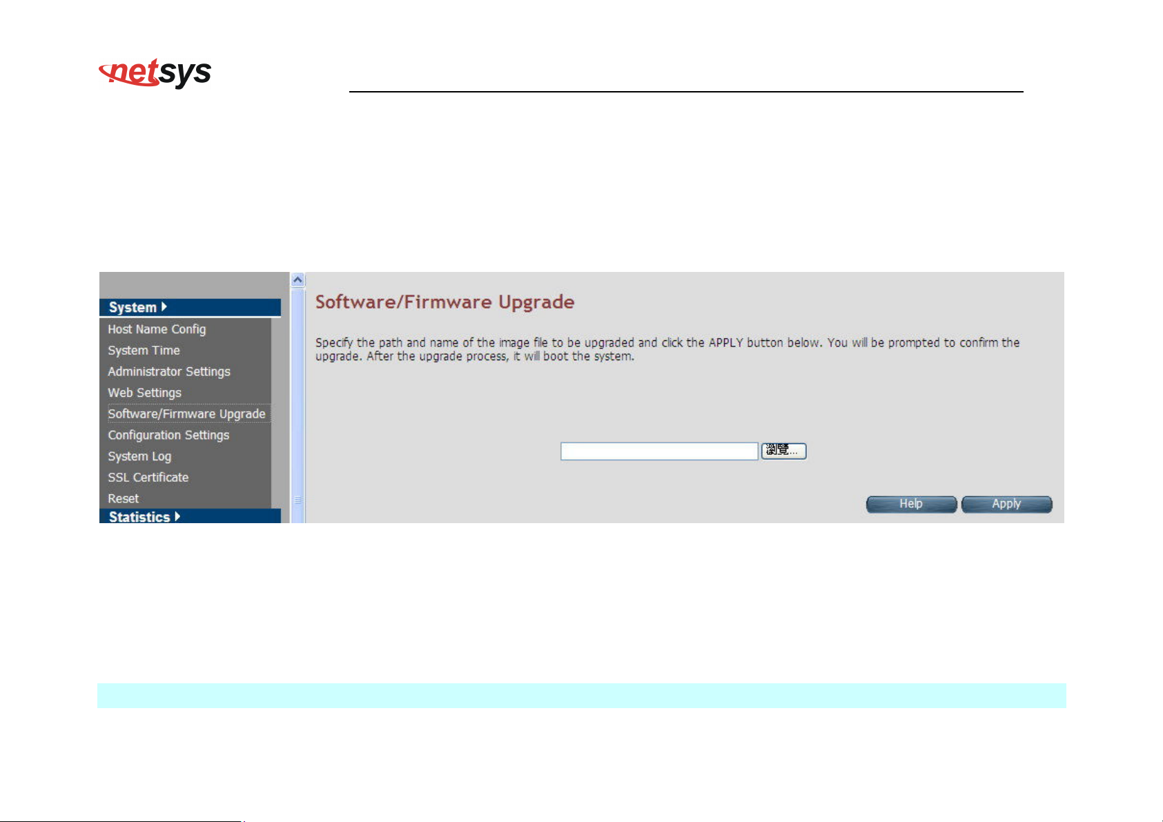
For updating the system firmware, click the Software/Firmware Upgrade link (System > Software/Firmware Upgrade) on
the left navigation bar. A screen displays the current version of NV-600WI Software running on the device as shown in Figure
4.3.5
Figure 4.3.5 Software/Firmware Upgrade
Click Browse to specify the software image file from host, to be upgraded in system.
Click Apply to start the software upgrade process.
Note:
You can click Home on the left navigation bar to view the current software version.
51
Page 53
NV-600WI Managed Industrial Grade Wireless VDSL2 Router USER’S MANUAL Ver. A2
4.3.6 Configuration Settings
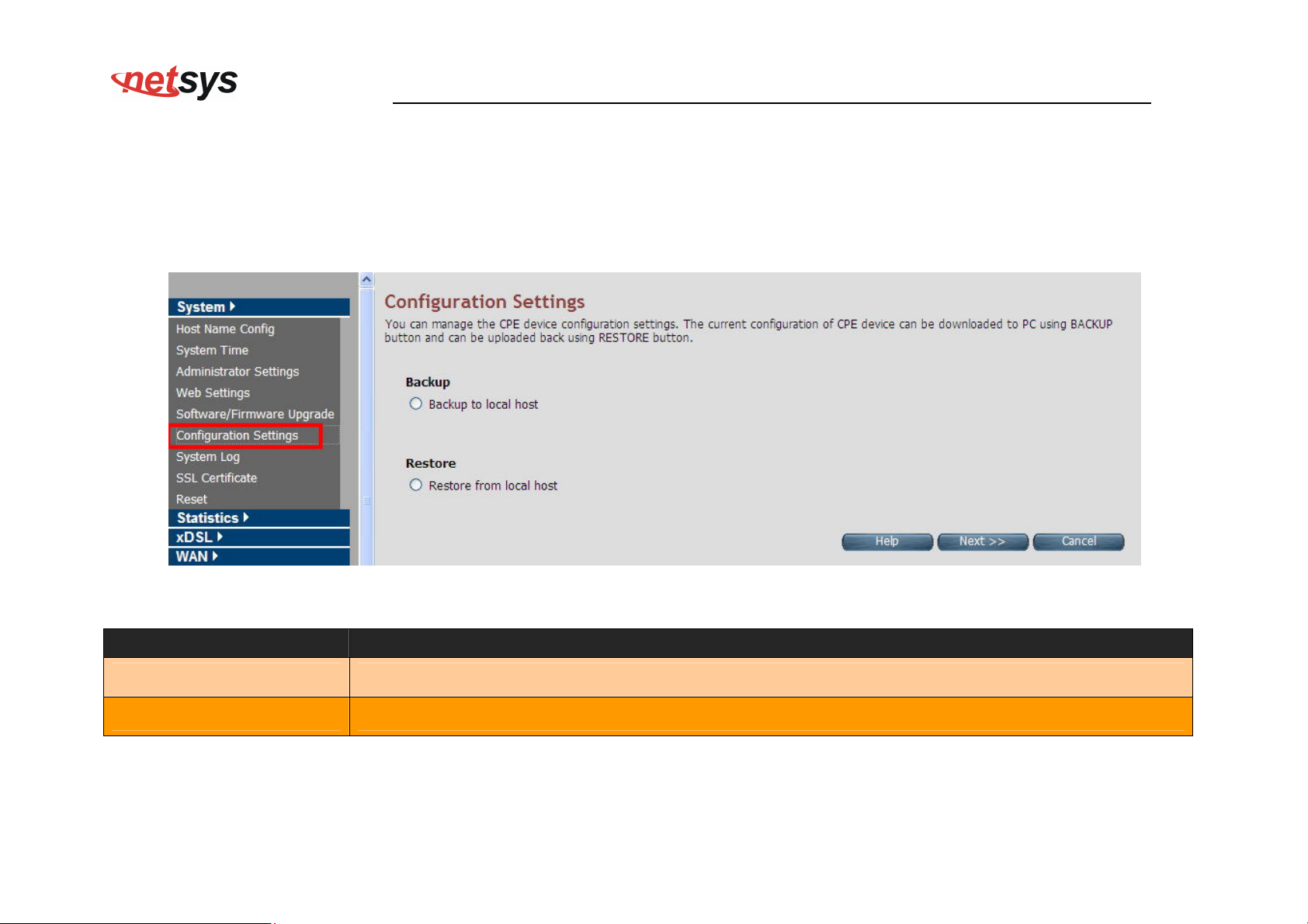
For managing the configuration of the system, click the Configuration Settings link (System > Configuration Settings) on
the left navigation bar. This page allows users to backup the current configuration of CPE to host PC or restore the previously
backed-up configuration in host PC to CPE as displayed in Figure 4.3.6
Figure 4.3.6 Configuration Settings
Fields in Configuration Settings
Field Description
Backup to local host This will backup the current active configuration of CPE in Host machine.
Restore from local host This will load the user supplied configuration to CPE from Host machine.
Click Next to start the firmware upgrade process.
Click Cancel to exit from this page without saving the changes.
52
Page 54
NV-600WI Managed Industrial Grade Wireless VDSL2 Router USER’S MANUAL Ver. A2
Backup Current Active Configuration
As mentioned before, this option allows users to backup the current active configuration running in the router system. This is very
helpful, when a user wants to backup the current working configuration of the router for rollbacks, if required in future. It is
recommended that before any complex nature of configuration is done by user the current active configuration should be backed up
in host machine. The Local Host Configuration backup is shown in Figure 4.3.6.1
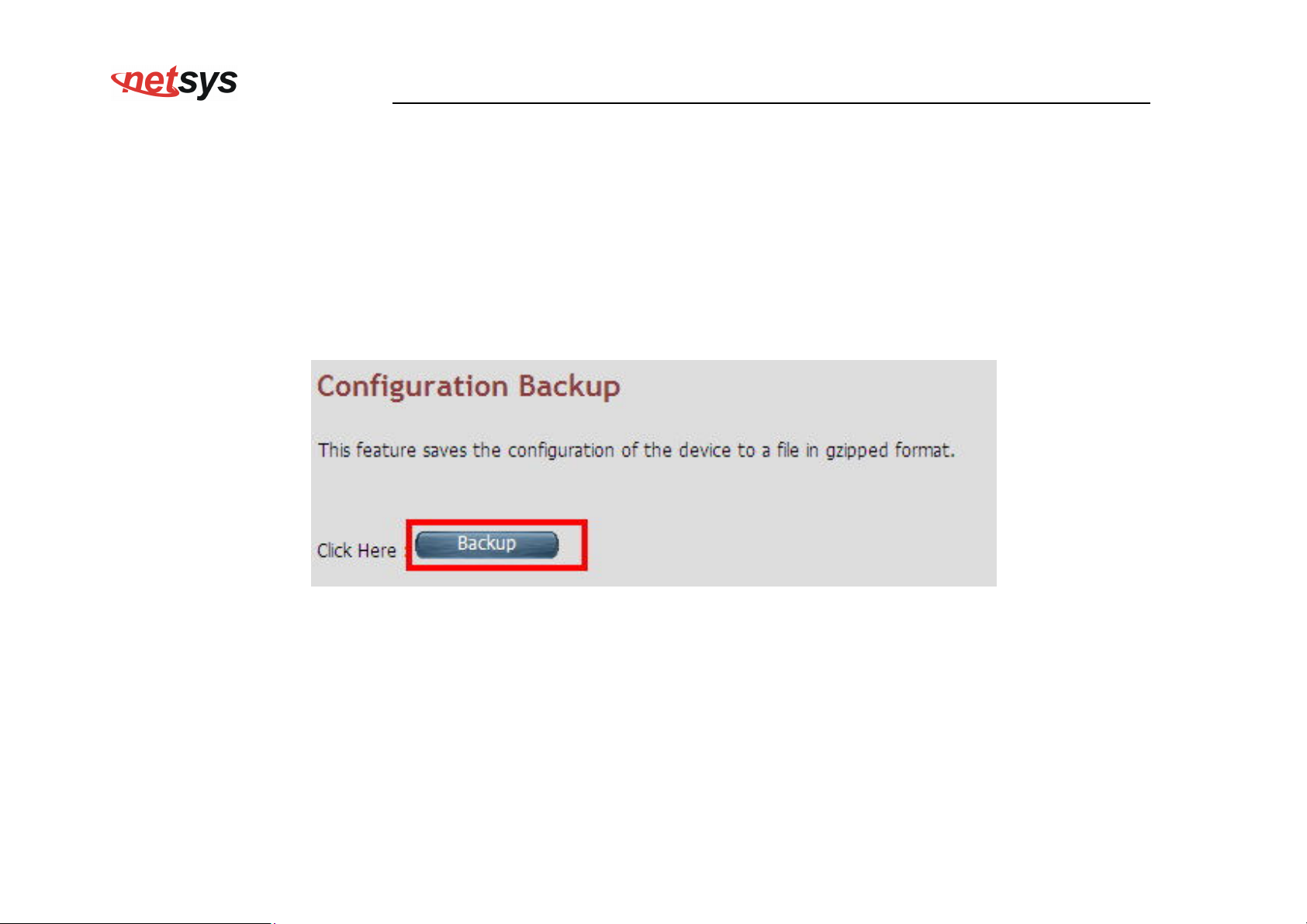
Figure 4.3.6.1 Configuration Backup
When you click the Backup button as shown in Figure 4.3.6.1, it will backup the configuration settings of CPE in connected PC from
where Web UI is being accessed.
53
Page 55
NV-600WI Managed Industrial Grade Wireless VDSL2 Router USER’S MANUAL Ver. A2
Restore Previous Backed-up Configuration
As mentioned before this option allows the user to restore the earlier backed up configuration in router system. This operation is
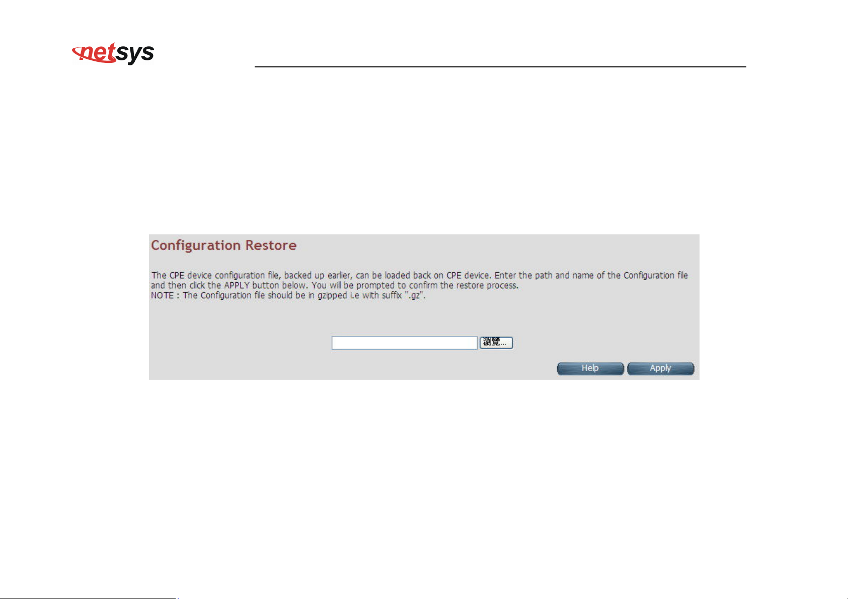
handy for restoring the system to last backed-up configuration mode. The Local Host Configuration restore is shown in Figure 4.3.6.2.
The system will reboot after the configuration is restored. When the CPE boots up, it will be running with the newly applied
configuration.
Figure 4.3.6.2 Configuration Restore
Click Apply button to restore the configuration settings.
54
Page 56
NV-600WI Managed Industrial Grade Wireless VDSL2 Router USER’S MANUAL Ver. A2
4.3.7 System Log
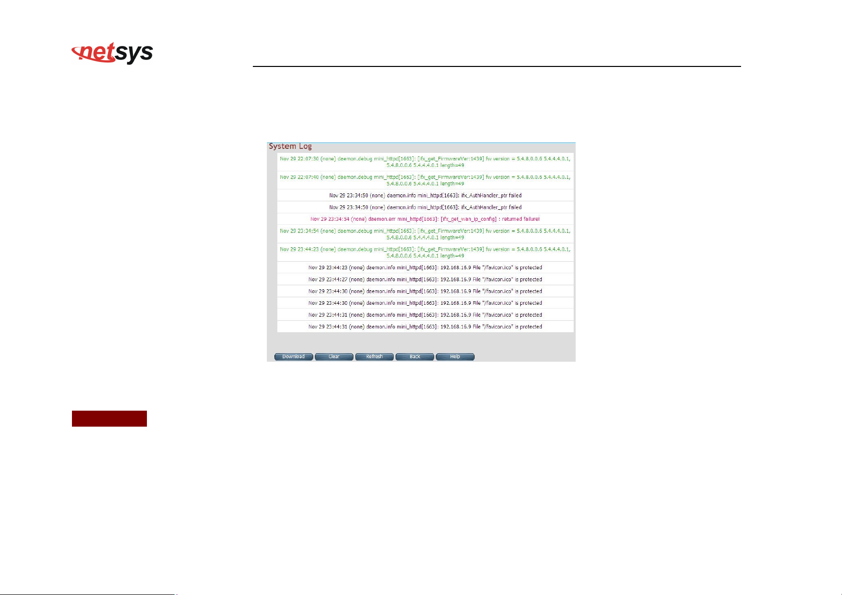
For viewing the logs produced in the system, click the System Log link (System > System Log) on the left navigation bar. A
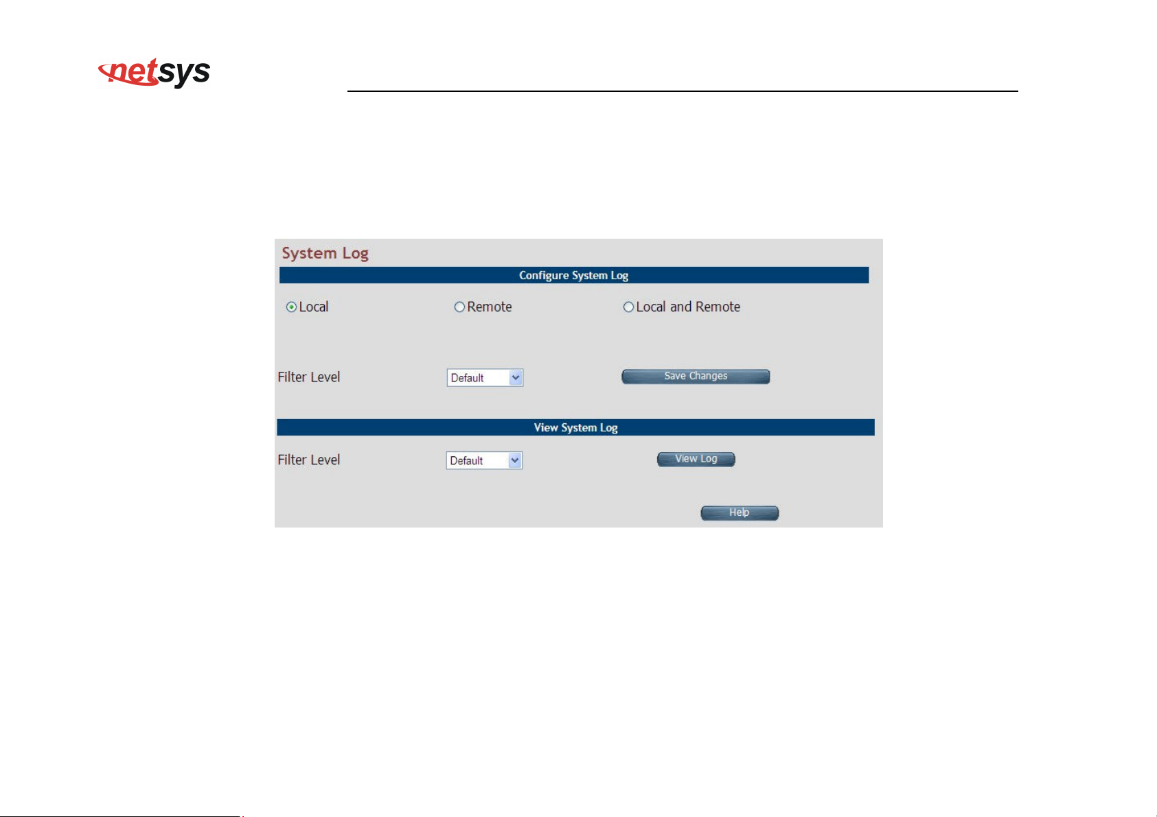
screen is displayed as shown in Figure 4.3.7
Figure 4.3.7 System Log
This page allows managing logging options in CPE device.
If "Local" is selected, the events are logged locally in the system.
If "Remote" is selected, the messages are logged to a remote server.
If "Local and Remote" option is selected, messages are logged locally in the system as well as to the remote server.
The events pertaining to the priority equal or higher to the selected level will be logged. "Default" level logs all events.
55
Page 57
NV-600WI Managed Industrial Grade Wireless VDSL2 Router USER’S MANUAL Ver. A2
For viewing system log, the events corresponding to the priority level equal to or higher than the selected level will be displayed here.
The screen contains the following details: Fields in System Log
Field Description
Select the mode of log. The possible options are:
Configure System Log
Local Mode: The log text is displayed in web browser itself.
Remote Mode: Specify the IP address and UDP port number for log transfer using syslog.
Local and Remote Mode: This supports both options mentioned above.
The user can apply one of the following filters to record logging above the specified level. Click on
<SAVE CHANGES> button for applying the log level selection.
Default: The default pre-selected levels of logs are recorded.
Debug: Debug and above levels of logs are recorded.
Info: Informative and above level of logs are recorded.
Filter Level
Notice: Notice type and above level of logs are recorded.
Warning: Warning type and above levels of logs are recorded.
Error: Error type and above levels of logs are recorded.
Critical: Critical type and above levels of logs are recorded.
Alert: Alert type and above level of logs are recorded.
Emerg: Emergency type of log information is recorded.
The user can apply one of the following filters to view specific logs of certain level:
Default: The default pre-selected levels of logs are viewed.
Debug: Debug and above levels of logs are viewed.
Info: Informative and above level of logs are viewed.
View System Log
Notice: Notice type and above level of logs are viewed.
Warning: Warning type and above levels of logs are viewed.
Error: Error type and above levels of logs are viewed.
Critical: Critical type and above levels of logs are viewed.
Alert: Alert type and above level of logs are viewed.
Emerg: Emergency type of log information is viewed.
Click Save Changes to configure the system log settings.
56
Page 58
NV-600WI Managed Industrial Grade Wireless VDSL2 Router USER’S MANUAL Ver. A2
Click View Log to fetch the logs in browser.
When you click View log button, a screen is displayed as shown in Figure 4.3.7.1. This screen is an example of system log of default
level as shown in the browser.
Figure 4.3.7.1 View System Log
For the ease of readability, the log messages of different levels are using different colors.
For example: all the debug messages are shown in green colored text.
Click Download to save the file in Host Computer.
Click Clear to clear the log from the system.
Click Refresh to get the recent log.
Click Back to go back to System Log page.
57
Page 59
NV-600WI Managed Industrial Grade Wireless VDSL2 Router USER’S MANUAL Ver. A2
4.3.8 SSL Certificate
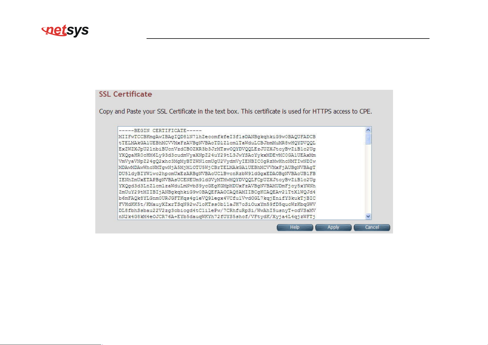
For installing a SSL Certificate for SSL tunnel, click the SSL Certificate link (System > SSL Certificate) on the left navigation bar. A
screen is displayed as shown in Figure 4.3.8
Figure 4.3.8 SSL Certificate
Click Apply to install the entered certificate.
Click Cancel to cancel the installation of entered certificate.
58
Page 60
NV-600WI Managed Industrial Grade Wireless VDSL2 Router USER’S MANUAL Ver. A2
4.3.9 Reset
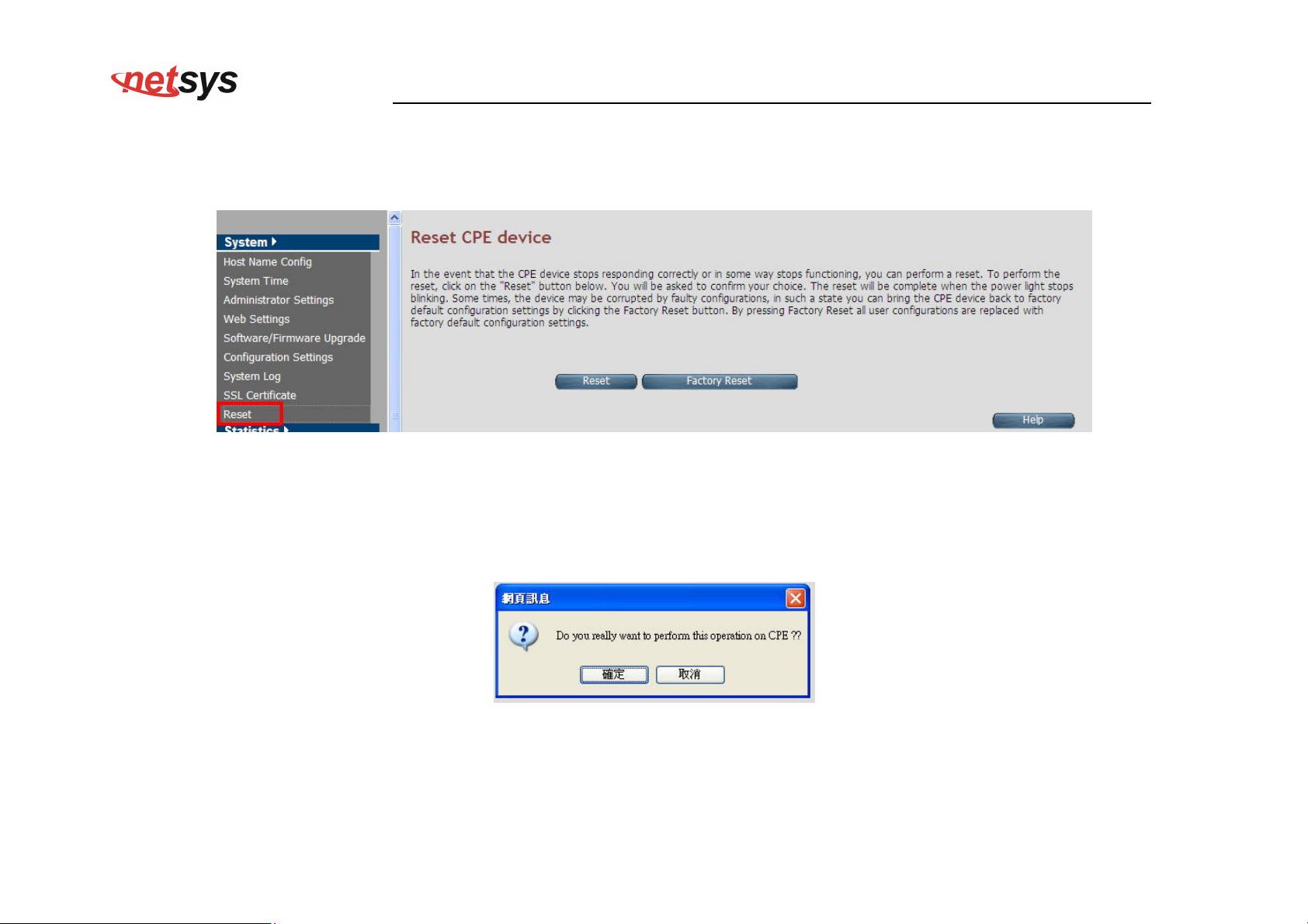
To reboot the system, click Reset link (System > Reset) on the left navigation bar. A screen is displayed as shown in Figure 4.3.9
Figure 4.3.9 Reset
Click Reset to reboot the system. This does not change the configurations existing in system.
Click Factory Reset to reset the device configuration to factory defaults configuration. This operation will result in saving the
current configuration and reverted back to factory shipped configuration.
When Reset or Factory Reset is clicked, a confirmation message is displayed as shown in Figure 4.3.9.1
Figure 4.3.9.1 Reset Confirmation Message
Click Ok to perform the operation on CPE.
Click Cancel to exit from this page.
59
Page 61
NV-600WI Managed Industrial Grade Wireless VDSL2 Router USER’S MANUAL Ver. A2
4.4 Select “Statistics”
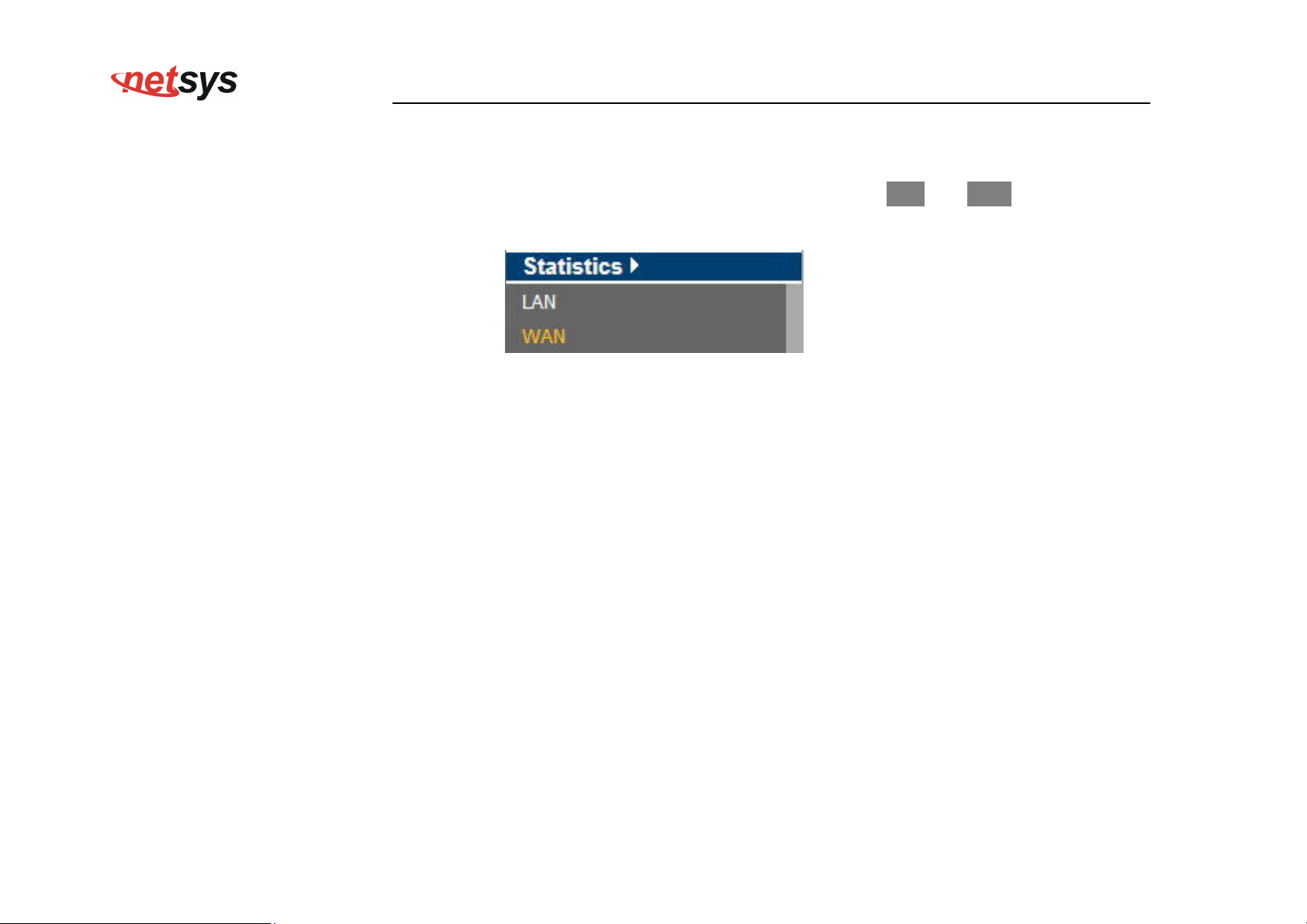
Select the “Statistics” link on left navigation menu. The menu below includes the sub-menus of LAN and WAN. A screen is displayed
as shown in Figure 4.4.
Figure 4.4 Statistics in the left navigator bar
60
Page 62
NV-600WI Managed Industrial Grade Wireless VDSL2 Router USER’S MANUAL Ver. A2
4.4.1 LAN
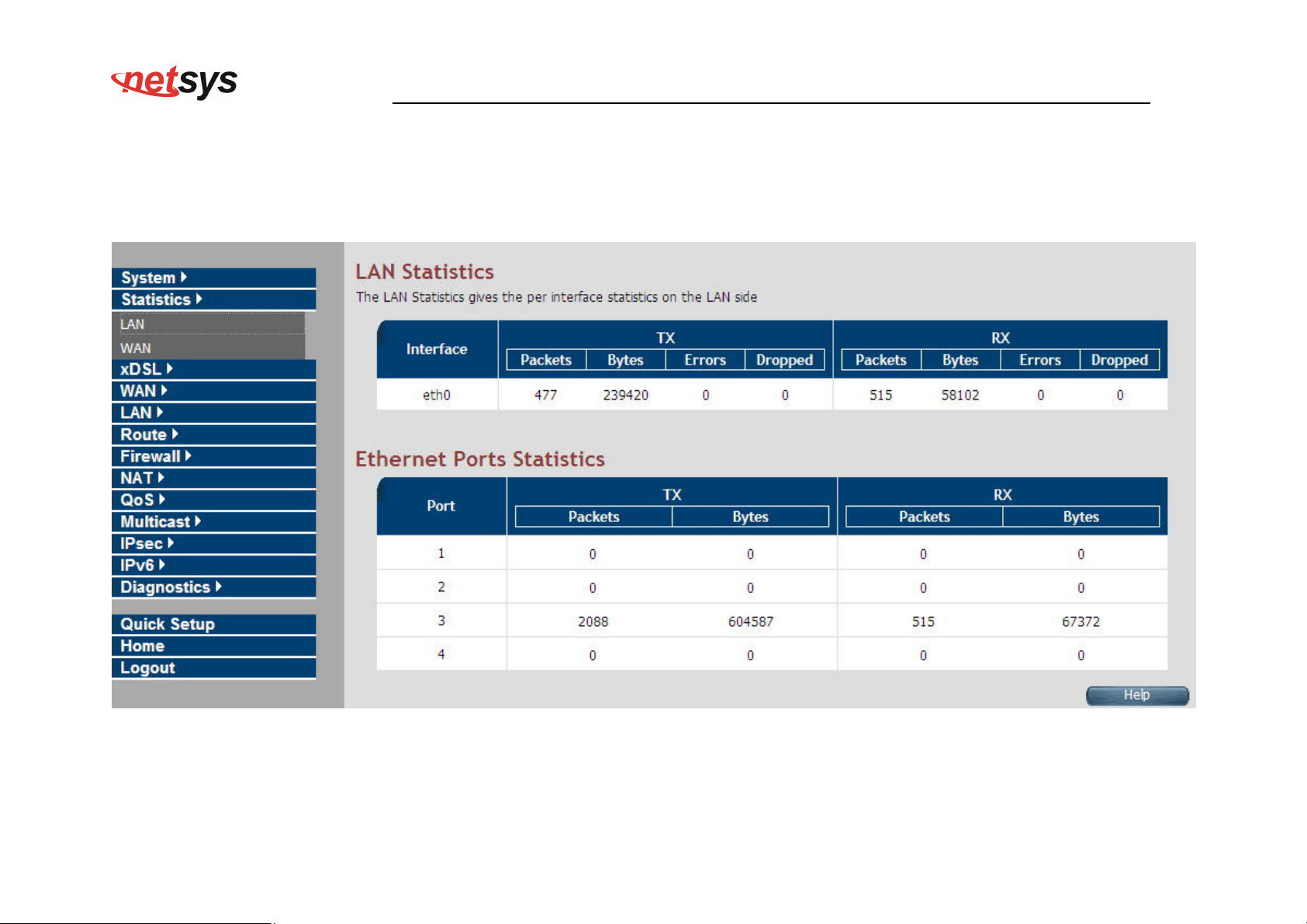
For viewing the LAN Statistics, click the LAN link (Statistics > LAN) on the left navigation bar. A screen is displayed as shown in
Figure 4.4.1
Figure 4.4.1 LAN Statistics
61
Page 63
NV-600WI Managed Industrial Grade Wireless VDSL2 Router USER’S MANUAL Ver. A2
The screen contains the following details:
Fields in LAN Statistics:
Field Description
Interface Name of LAN Interface (e.g. eth0, usb0 etc.)
Transmit Counters:
Total packets transmitted from this interface.
TX
Total bytes transmitted form this interface.
Total Error packets on this interface.
Total Dropped packets on this interface.
Receive Counters:
Total packets received from this interface.
RX
Total bytes received form this interface.
Total Erroneous packets on this interface.
Total Dropped packets on this interface.
62
Page 64
NV-600WI Managed Industrial Grade Wireless VDSL2 Router USER’S MANUAL Ver. A2
4.4.2 WAN
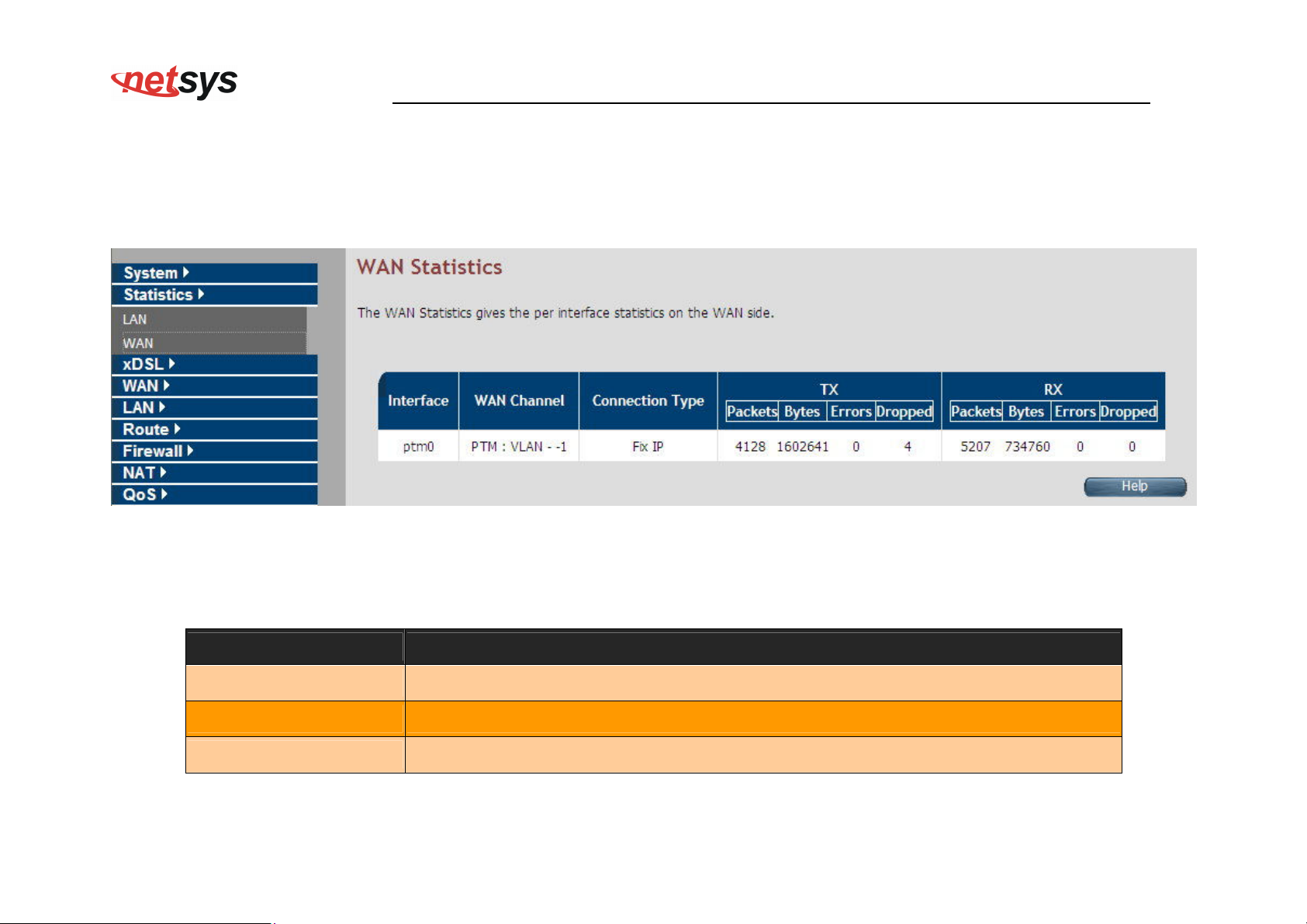
For viewing WAN Statistics, click the WAN link (Statistics > WAN) on the left navigation bar. A screen is displayed as shown in
Figure 4.4.2
Figure 4.4.2 WAN Statistics
The screen contains the following details:
Fields in WAN Statistics:
Field Description
Interface
Name of WAN Interface.
WAN Channel Information about WAN Channel such as VCC or WAN-Ethernet channel.
Connection Type
Type of WAN Connection.
63
Page 65
NV-600WI Managed Industrial Grade Wireless VDSL2 Router USER’S MANUAL Ver. A2
Fields in WAN Statistics (cont’d):
Field Description
Transmit Counters for WAN interface:
Total packets transmitted from this interface.
TX
Total bytes transmitted form this interface.
Total Erroneous packets transmitted on this interface.
Total Dropped packets transmitted on this interface.
Receive Counters for WAN interface:
Total packets received from this interface.
RX
Total bytes received form this interface.
Total Erroneous packets received on this interface.
Total Dropped packets on this interface.
64
Page 66
NV-600WI Managed Industrial Grade Wireless VDSL2 Router USER’S MANUAL Ver. A2
4.5 Select “xDSL”
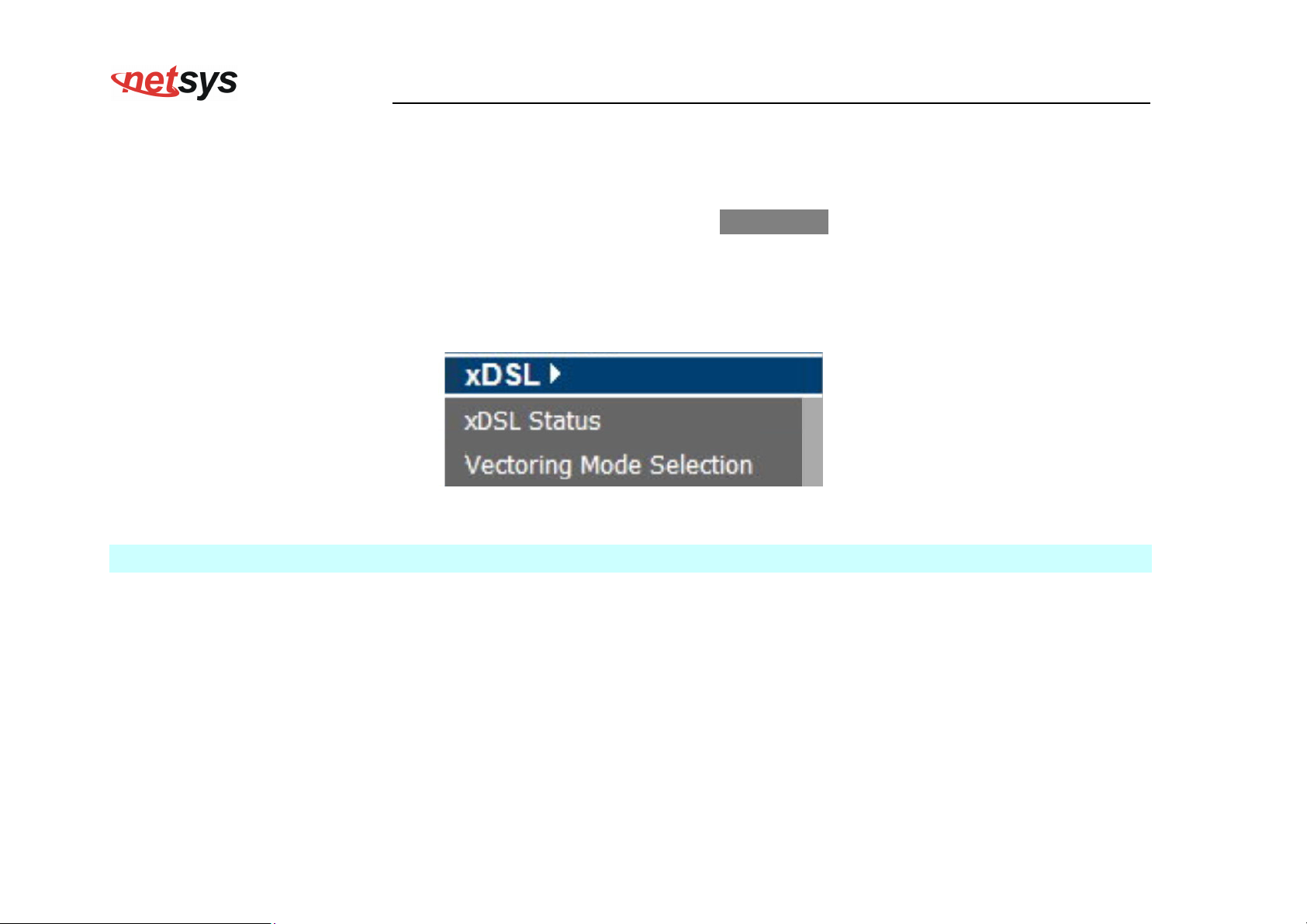
You can view the xDSL link on the left navigation bar of the CPE Home page. This web page is available only on DSL
platforms. Select the “xDSL”. The menu below includes the sub-menus of xDSL Status. A screen is displayed as shown in
Figure 4.5.
Figure 4.5 Select xDSL
Note:
These options help to monitor and configure the DSL physical parameters in the device.
65
Page 67
NV-600WI Managed Industrial Grade Wireless VDSL2 Router USER’S MANUAL Ver. A2
4.5.1 xDSL Status
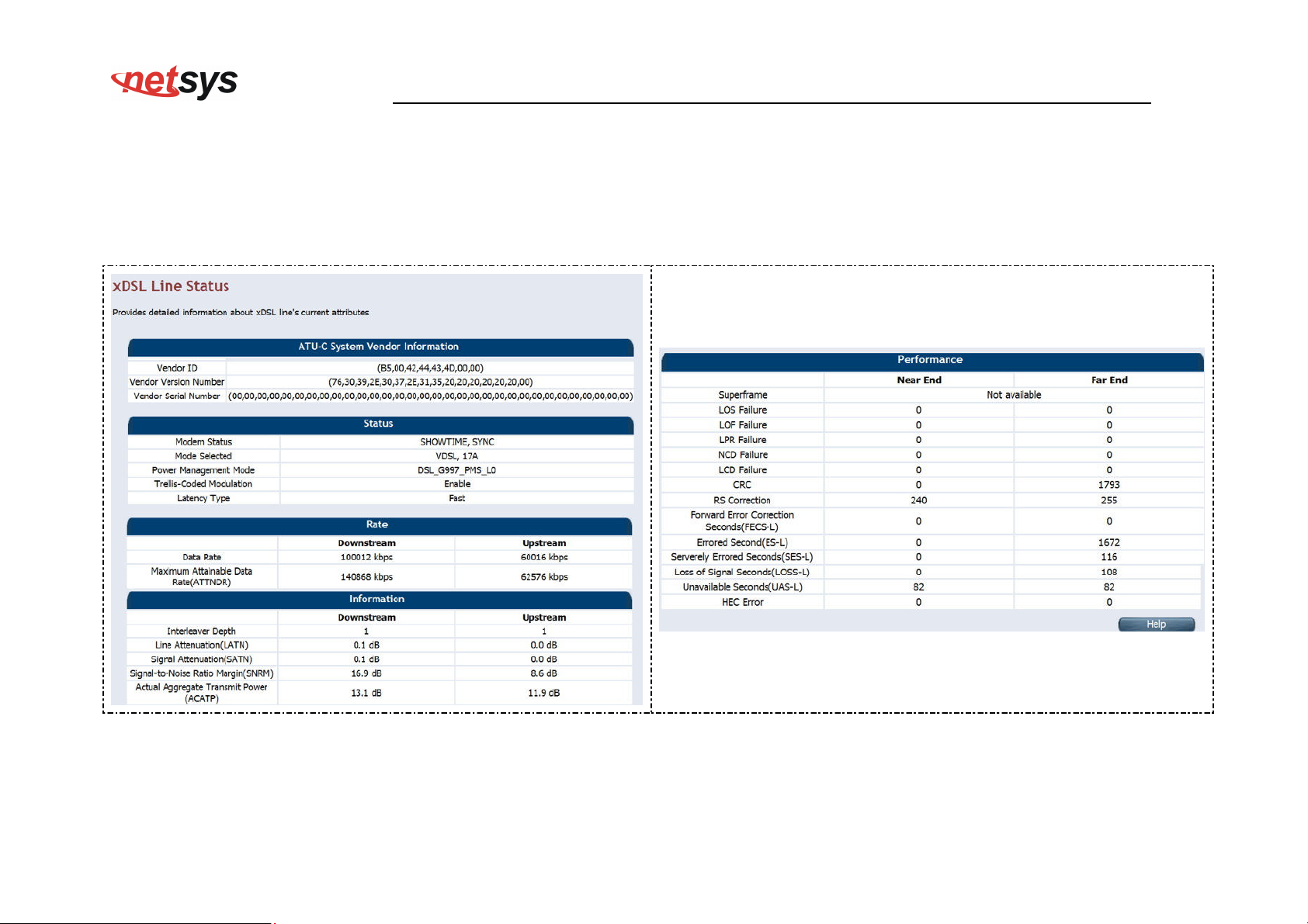
For viewing the xDSL Status, click the xDSL Status link (xDSL > xDSL Status) on the left navigation bar. A screen is displayed as
shown in Figure 4.5.1
Figure 4.5.1 xDSL Status
66
Page 68
NV-600WI Managed Industrial Grade Wireless VDSL2 Router USER’S MANUAL Ver. A2
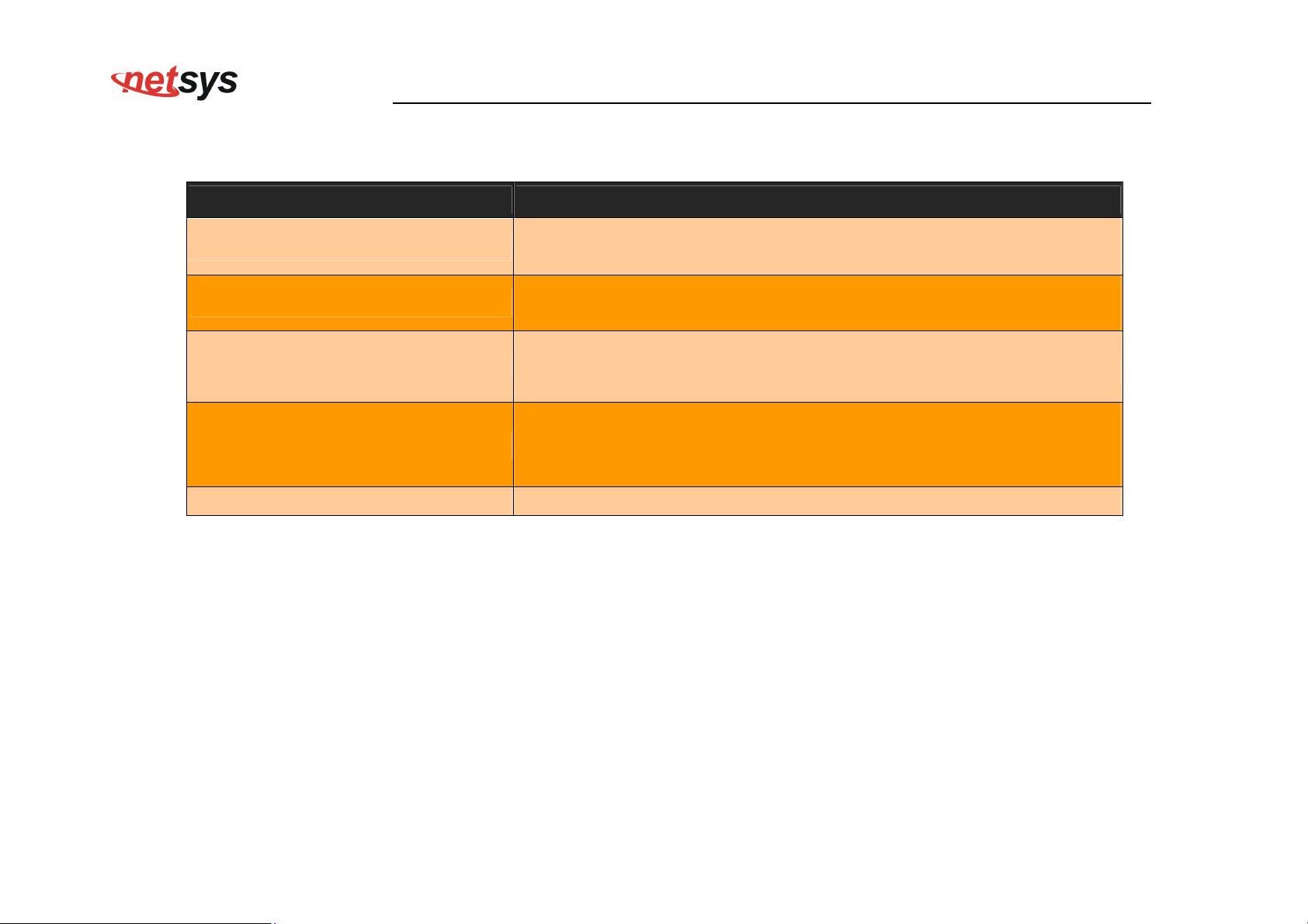
The screen contains the following details:
Fields in xDSL Status:
Field Description
ATU-C System Vendor Information
Displays the Vendor ID, Version Number and the Serial Number of the
ATU-C (DSLAM).
Displays the status of the physical xDSL Line in terms of the modem,
Status
mode selected, Trellis-Coded Modulation and the Latency Type
Rate Displays the data rate and the maximum attainable data rate
Displays the information about the xDSL line, in terms of Line
Information
Attenuation, Signal Attenuation, Signal to Noise Ratio and other such
parameters
Performance Displays the performance figures of the physical xDSL line
67
Page 69
4.5.2 Vectoring Mode selection
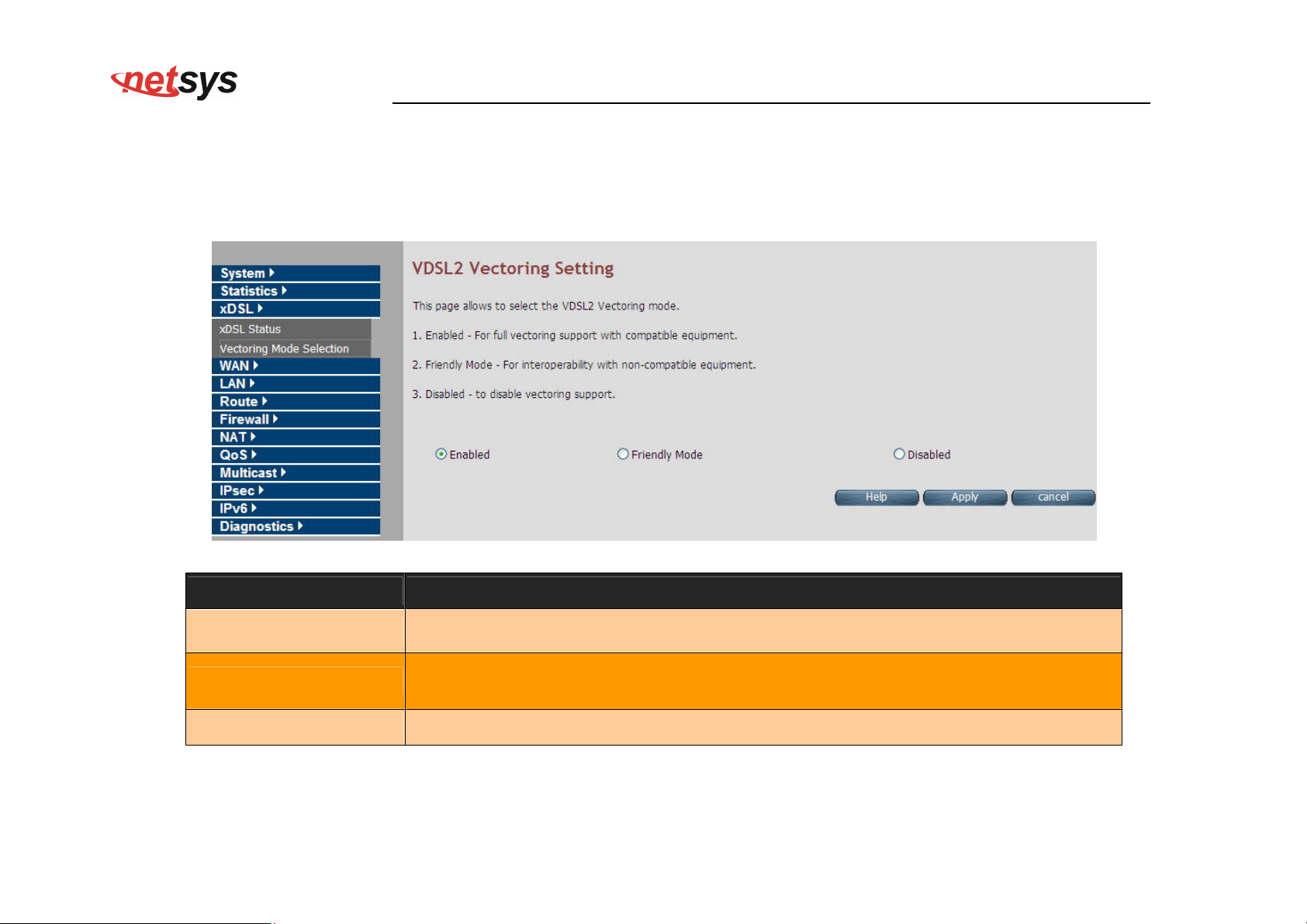
For viewing the vectoring mode, click the Vectoring Mode Selection link (xDSL > Vectoring Mode Selection) on the left navigation
bar. A screen is displayed as shown in Figure 4.5.2
Fields in Vectoring Mode Selection
NV-600WI Managed Industrial Grade Wireless VDSL2 Router USER’S MANUAL Ver. A2
Field Description
Enabled
Friendly Mode
Disabled Disable VDSL2 Vectoring feature.
Enable VDSL2 Full Vectoring mode (Default setting), it will auto follow the CO side
vectoring configuration.
Enable VDSL2 Vectoring-Friendly mode, it will auto follow the CO side vectoring
configuration.
68
Page 70
Notes:
1. NV-600WI vdsl2 vectoring technology default setting is enabled.
2. If user would like to use vectoring technology, NV-600WI and IP DSLAM both need support vectoring technology and need both
enabled. NV-600WI will auto follow the IP DSLAM vectoring technology to configure.
3. Vectoring technology does not support point to point applications.
NV-600WI Managed Industrial Grade Wireless VDSL2 Router USER’S MANUAL Ver. A2
About vectoring function(Reference only):
Vectoring is a transmission method that employs the coordination of line signals for reduction of crosstalk levels and improvement of
performance. It is based on the concept of noise cancellation, much like noise-cancelling headphones. The ITU-T G.993.5 standard,
"Self-FEXT cancellation (vectoring) for use with VDSL2 transceivers" (2010), also known as G.vector, describes vectoring for VDSL2.
The scope of Recommendation ITU-T G.993.5 is specifically limited to the self-FEXT (far-end crosstalk) cancellation in the
downstream and upstream directions. The far end crosstalk (FEXT) generated by a group of near-end transceivers and interfering
with the far-end transceivers of that same group is cancelled. This cancellation takes place between VDSL2 transceivers, not
necessarily of the same profile.
69
Page 71
NV-600WI Managed Industrial Grade Wireless VDSL2 Router USER’S MANUAL Ver. A2
4.6 Select “WAN”
You can view WAN link on the left navigation bar for WAN related settings. Select the “NAT”. The menu below includes the
sub-menus of WAN Mode Selection, WAN Channel Config, VLAN Channel Config, WAN Setting, WAN Status, DNS, DDNS,
and OAM Configuration. A screen is displayed as shown in Figure 4.6.
Figure 4.6 WAN options
70
Page 72
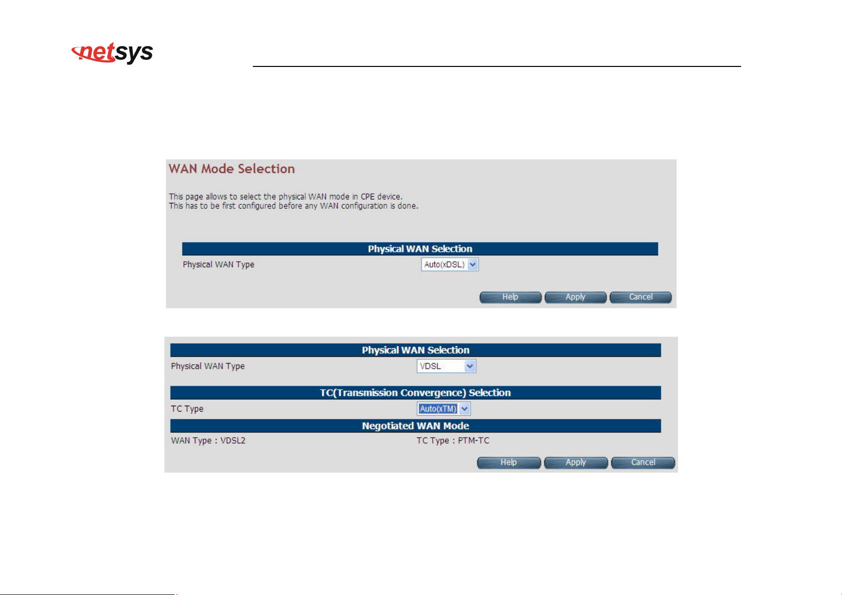
NV-600WI Managed Industrial Grade Wireless VDSL2 Router USER’S MANUAL Ver. A2
4.6.1 WAN Mode Selection
For configuring the WAN Mode Setting, click the WAN Mode Selection (WAN > WAN Mode Selection) on the left navigation
bar. A screen is displayed as shown in Figure 4.6.1
Figure 4.6.1 WAN Mode Setting (Selected Auto)
Figure 4.6.1.1 WAN Mode Setting (Selected ADSL2+ / VDSL2)
71
Page 73
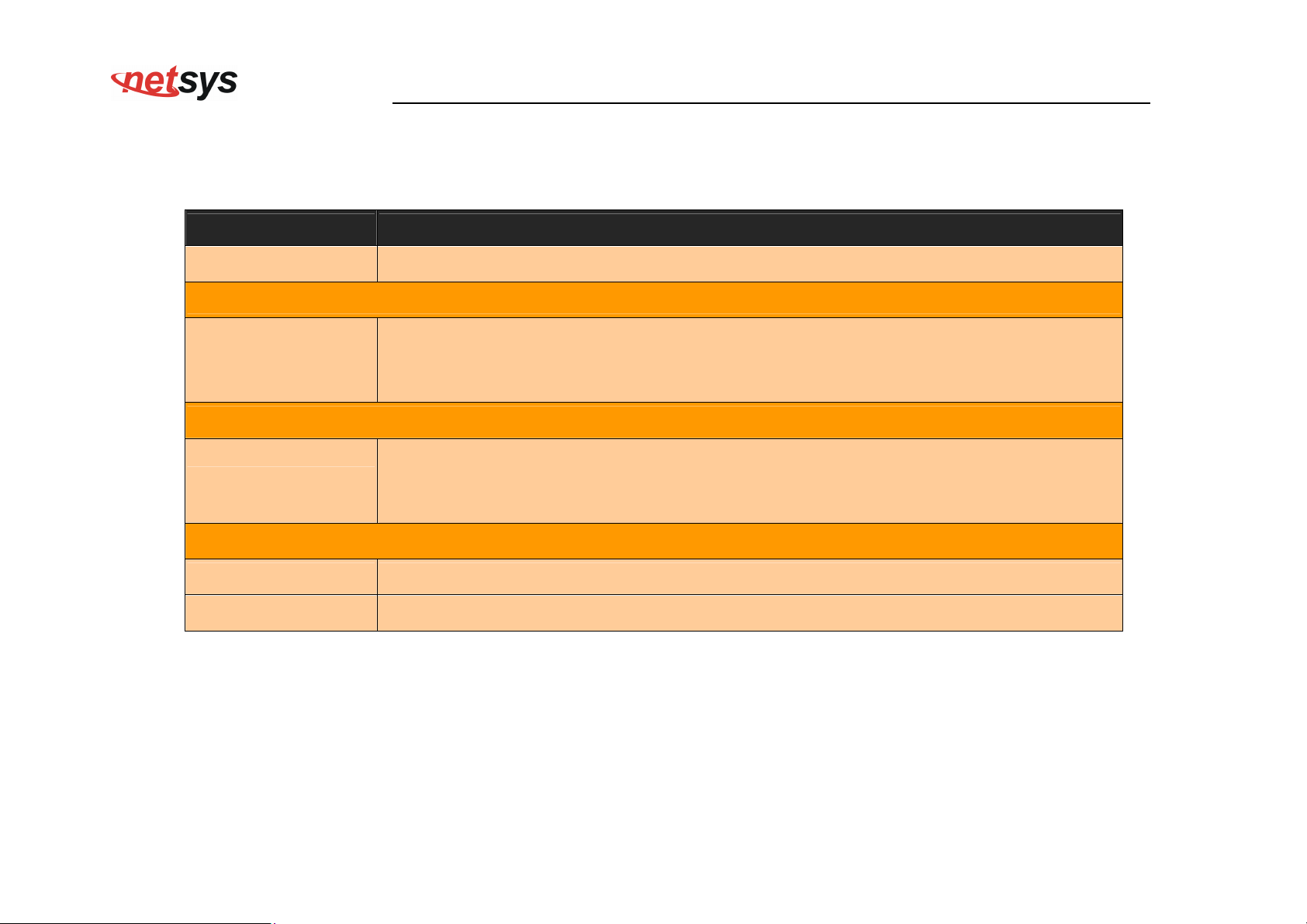
ADSL2+, VDSL2, xDSL (Auto), WAN
NV-600WI Managed Industrial Grade Wireless VDSL2 Router USER’S MANUAL Ver. A2
The screen contains the following details:
Fields in WAN Mode Setting:
Field Description
Failover Support Select this checkbox to enable Dual WAN support.
Primary WAN Selection
Choose the WAN type from the drop down list. For multi-WAN mode supported CPE
Physical WAN Type
image the dropdown will present following options -
Ethernet over MII-0, WAN Ethernet over MII-1, 3G WAN and LTE WAN.
TC (Transmission Convergence) Selection
Choose the Transmission Convergence from the drop down list - 1). ATM-TC or
TC Type
2).PTM-TC or 3). Auto. This field is displayed, only if ADSL2+ or xDSL is chosen as the
WAN type.
Negotiated WAN Mode
WAN Type Show WAN type status
TC Type Show TC type status
Click Apply at any time during configuration to save the information that you have entered.
Click Cancel to exit from this page without saving the changes.
72
Page 74
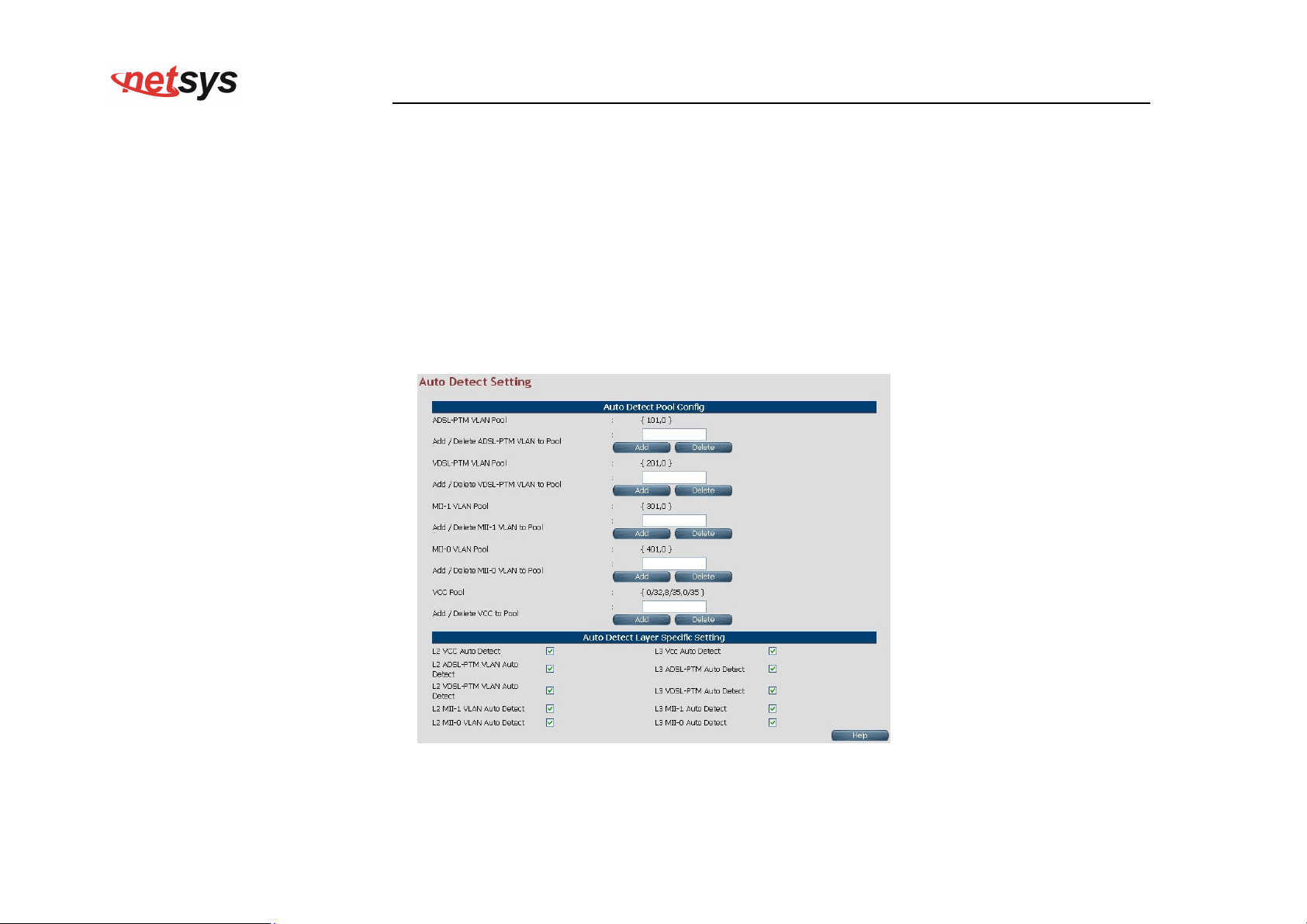
NV-600WI Managed Industrial Grade Wireless VDSL2 Router USER’S MANUAL Ver. A2
4.6.2 Auto Detect Setting
Auto detect feature is a fully automatic way to find and configure the VC channel or VLAN channel for active WAN PHY of the device
and WAN protocol for the same (either PPPoE/DHCP).
User has to provide pool of VC channels or VLAN channels which will be probed one by one sequentially and upon successful
detection of a channel, WAN protocol probing will be done and configured in the device.
For configuring the Auto Detect Config, click Auto Detect Config (WAN > Auto Detect Config) on the left navigation bar. A
screen is displayed as shown in Figure 4.6.2
Figure 4.6.2 Port Mapping Configuration
73
Page 75
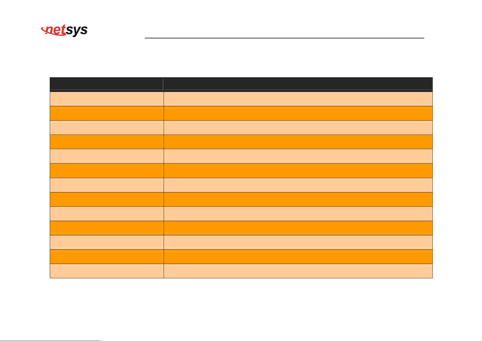
NV-600WI Managed Industrial Grade Wireless VDSL2 Router USER’S MANUAL Ver. A2
The screen contains the following details:
Fields in Auto detect Config:
Field Description
ADSL-PTM VLAN Pool This displays the current configured VLAN pool for AutoDetect in ADSL-PTM WAN mode.
Add/Delete ADSL-PTM VLAN to Pool Add or delete VLAN to ADSL-PTM VLAN pool.
VDSL-PTM VLAN Pool This displays the current configured VLAN pool for auto-detect in VDSL-PTM WAN mode.
Add/Delete VDSL-PTM VLAN to Pool Add or delete VLAN to VDSL-PTM VLAN pool.
MII-1 VLAN Pool This displays the current configured VLAN pool for auto-detect in MII-1 WAN mode.
Add/Delete MII-1 VLAN to Pool Add or delete VLAN to MII-1 VLAN pool.
MII-0 VLAN Pool This displays the current configured VLAN pool for auto-detect in MII-0 WAN mode.
Add/Delete MII-0 VLAN to Pool Add or delete VLAN to MII-0 VLAN pool.
VCC Pool This displays the current configured VCC pool for auto-detect in ADSL-ATM WAN mode.
Add/Delete VC to Pool Add or delete VCC to ADSL-ATM VCC pool.
L2 VCC Auto Detect Select this to enable VCC auto detection from the specified pool for ADSL-ATM WAN mode
L2 ADSL - PTM VLAN Auto Detect Select this to enable VLAN auto detection from the specified pool for ADSL - PTM WAN mode.
L2 VDSL - PTM VLAN Auto Detect Select this to enable VLAN auto detection from the specified pool for VDSL - PTM WAN mode.
74
Page 76
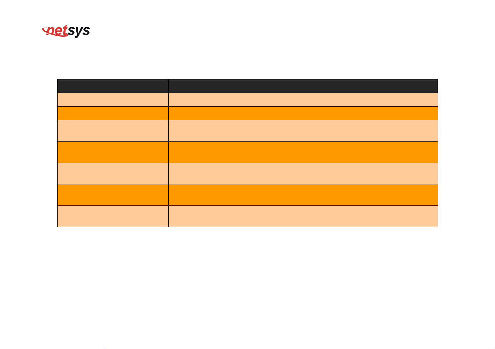
NV-600WI Managed Industrial Grade Wireless VDSL2 Router USER’S MANUAL Ver. A2
Fields in Auto detect Config(cont’d):
Field Description
L2 MII-1 VLAN Auto Detect Select this to enable VLAN auto detection from the specified pool for MII-1 WAN mode.
L2 MII-0 VLAN Auto Detect Select this to enable VLAN auto detection from the specified pool for MII-0 WAN mode.
L3 VCC Auto Detect
L3 ADSL - PTM VLAN Auto Detect
L3 VDSL - PTM VLAN Auto Detect
L3 MII-1 VLAN Auto Detect
L3 MII-0 VLAN Auto Detect
Select this to enable WAN auto detection (in sequence of PPPoE/DHCP) in ADSL-ATM
WAN mode.
Select this to enable WAN auto detection (in sequence of PPPoE/DHCP) in ADSL-PTM
WAN mode.
Select this to enable WAN auto detection (in sequence of PPPoE/DHCP) in VDSL-PTM
WAN mode.
Select this to enable WAN auto detection (in sequence of PPPoE/DHCP) in MII-1 WAN
mode.
Select this to enable WAN auto detection (in sequence of PPPoE/DHCP) in MII-0 WAN
mode.
75
Page 77
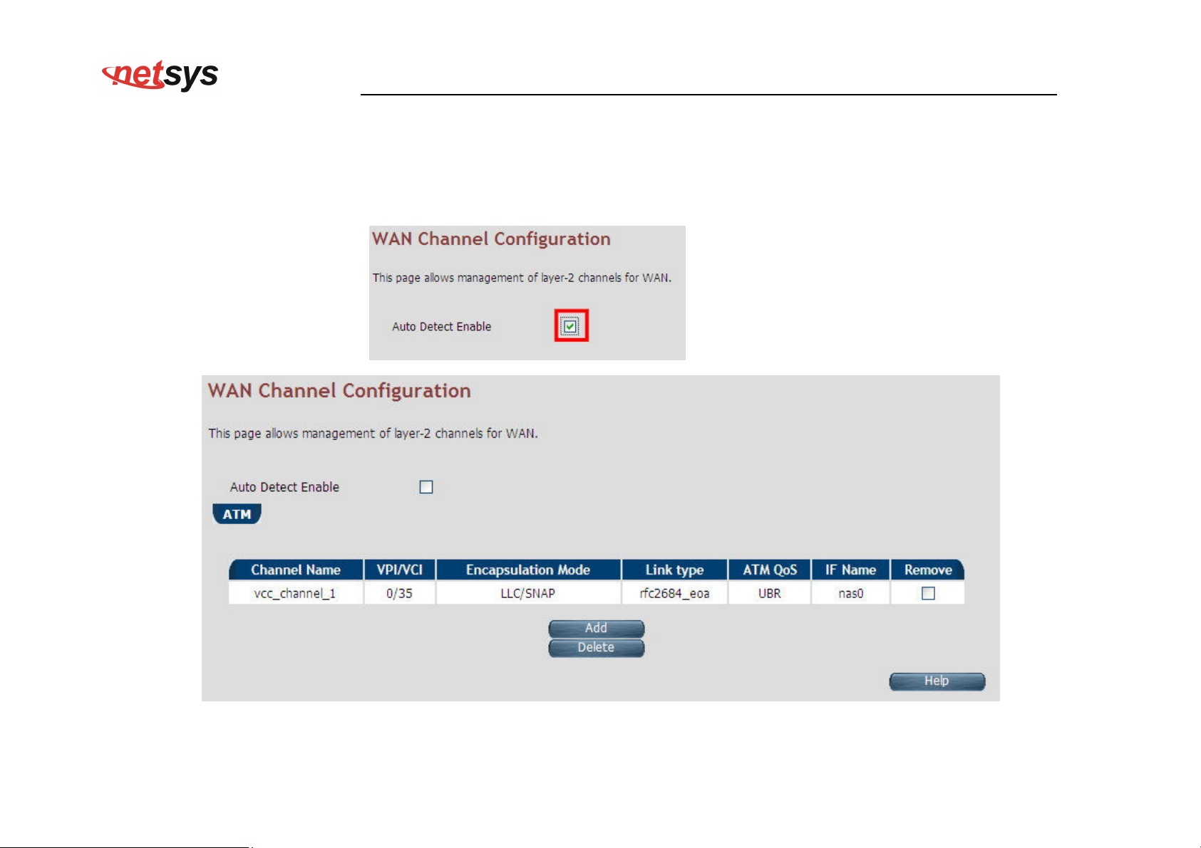
NV-600WI Managed Industrial Grade Wireless VDSL2 Router USER’S MANUAL Ver. A2
4.6.3 WAN Channel Configuration
For configuring the WAN Channel Configuration, click the WAN Channel Config (WAN > WAN Channel Config) on the left
navigation bar. A screen is displayed as shown in Figure 4.6.3.
Figure 4.6.3
Figure 4.6.3.1 WAN Channel Configuration (Auto Detecting does not check the checkbox)
76
Page 78
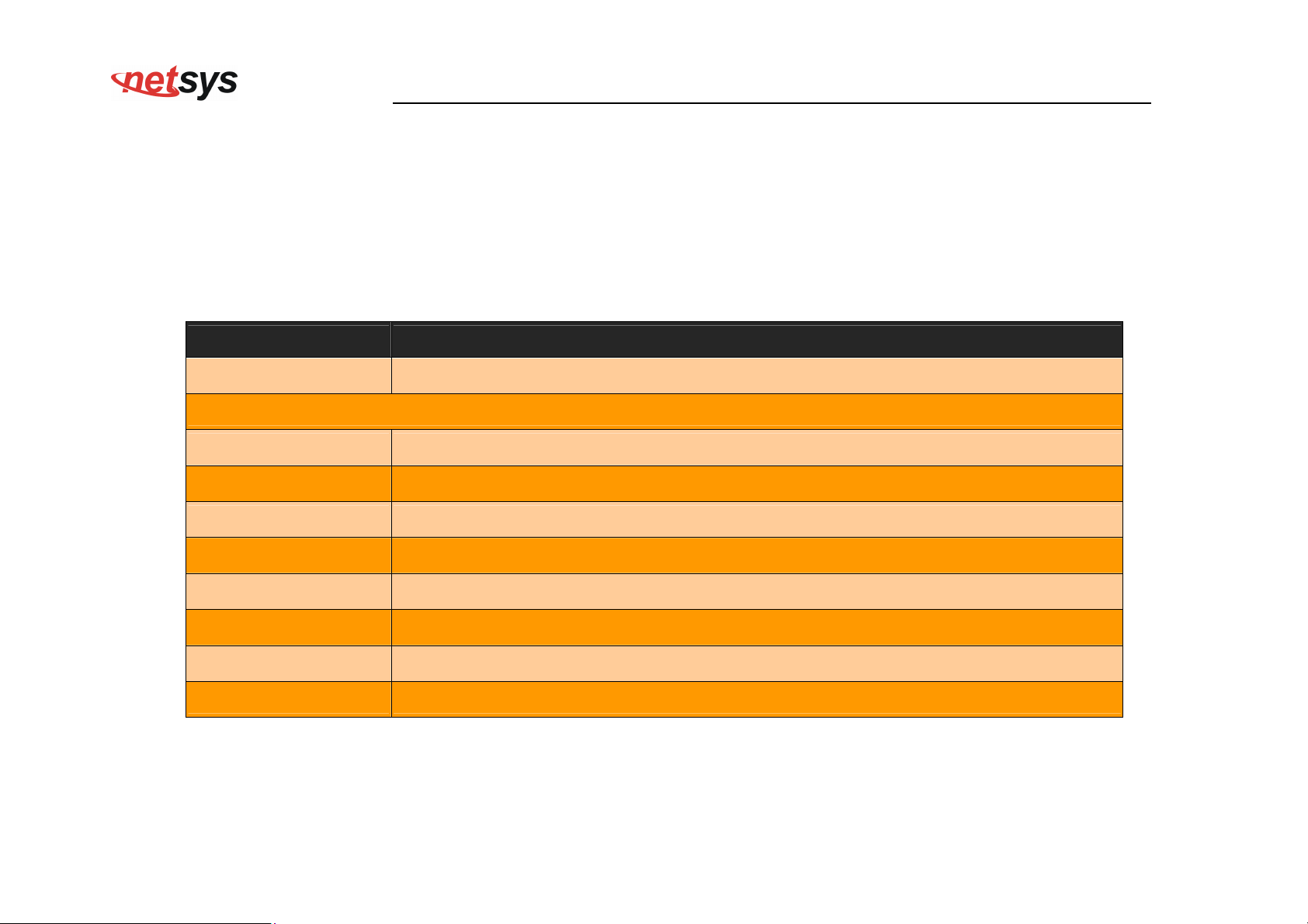
NV-600WI Managed Industrial Grade Wireless VDSL2 Router USER’S MANUAL Ver. A2
The screen contains the following details:
Fields in WAN Channel Configuration:
Field Description
ATM
The ATM based WAN channels are configured through the ATM tab.
Auto Detect Enable To enable Auto Detect.
Channel Name User specified VCC Name.
VPI/VCI Virtual Path Identifier and Virtual Channel Identifier.
Encapsulation Mode Encapsulation Mode for this VCC from dropdown - LLC/SNAP or VCMux mode.
Link type Shows AAL5 Link type for ATM VCC (values such as EoATM, IPoATM, PPPoATM).
ATM QoS Quality of Service for ATM VCC
IF Name ATM Channel interface name in system.
Remove Select this option to delete an ATM channel.
77
Page 79
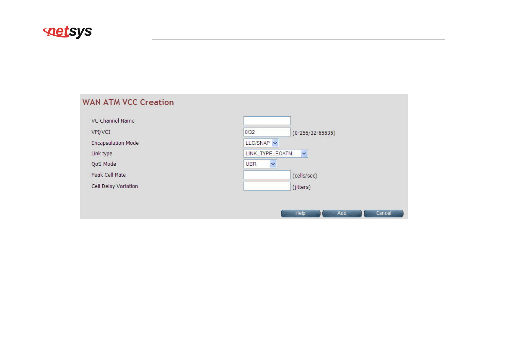
NV-600WI Managed Industrial Grade Wireless VDSL2 Router USER’S MANUAL Ver. A2
When you click Add inside the WAN Channel-ATM tab, a screen is displayed as shown in Figure 4.6.3.2
Figure 4.6.3.2 WAN Channel Configuration - ATM VCC Creation
The screen contains the following details:
78
Page 80
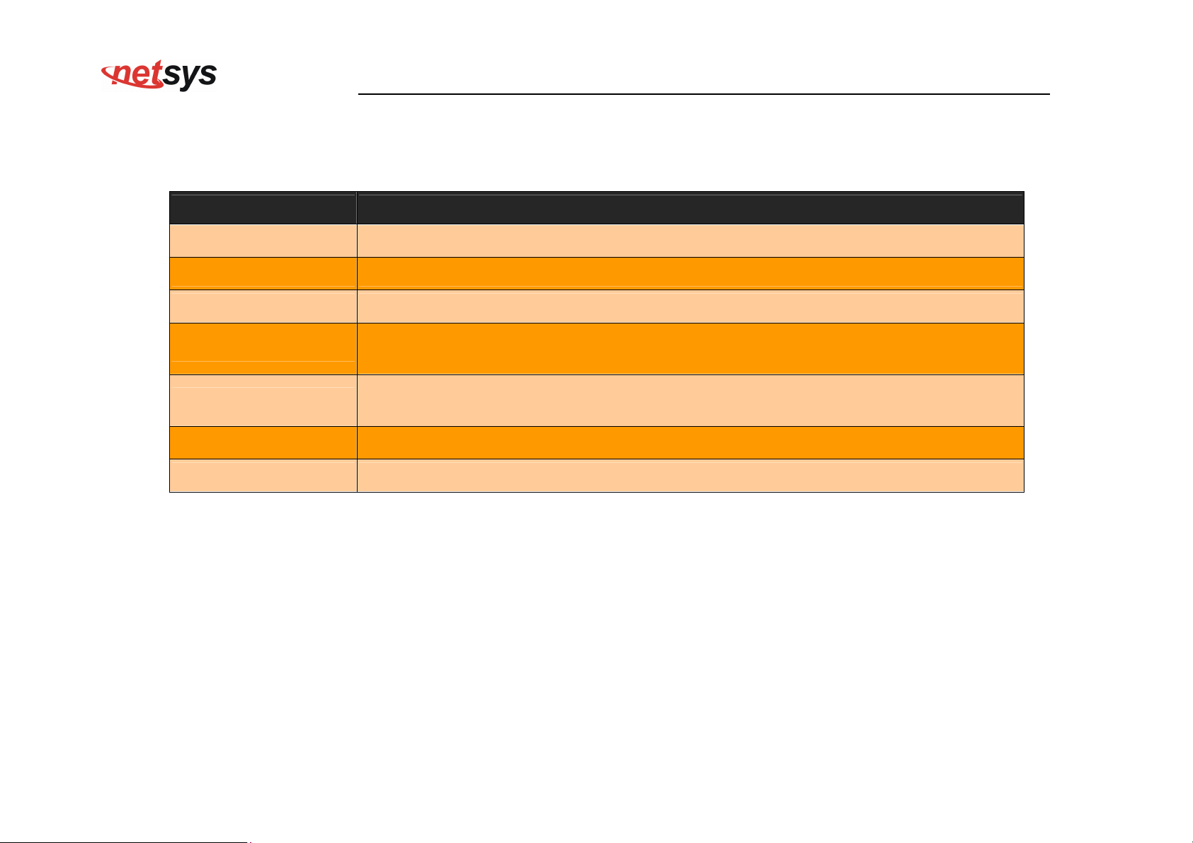
NV-600WI Managed Industrial Grade Wireless VDSL2 Router USER’S MANUAL Ver. A2
Fields in WAN Channel Configuration:
Field Description
VC Channel Name User specified VCC Name.
VCI/VPI Virtual Path Identifier and Virtual Channel Identifier
Encapsulation Mode Encapsulation Mode for this VCC from dropdown - LLC/SNAP or VCMux mode.
Link type
Select AAL5 Link type for ATM VCC (possible values such as EoATM, IPoATM,
PPPoATM).
Quality of Service for ATM VCC. Available options are UBR, CBR, rt-VBR, nrt-VBR
QoS Mode
and UBR+.
Peak Cell Rate Peak Cell Rate specified in cells/second.
Cell Delay Variation Cell Delay Variation specified in terms of jitters.
Click Add to save the information that you have entered.
Click Cancel to exit from this page without saving the changes.
79
Page 81
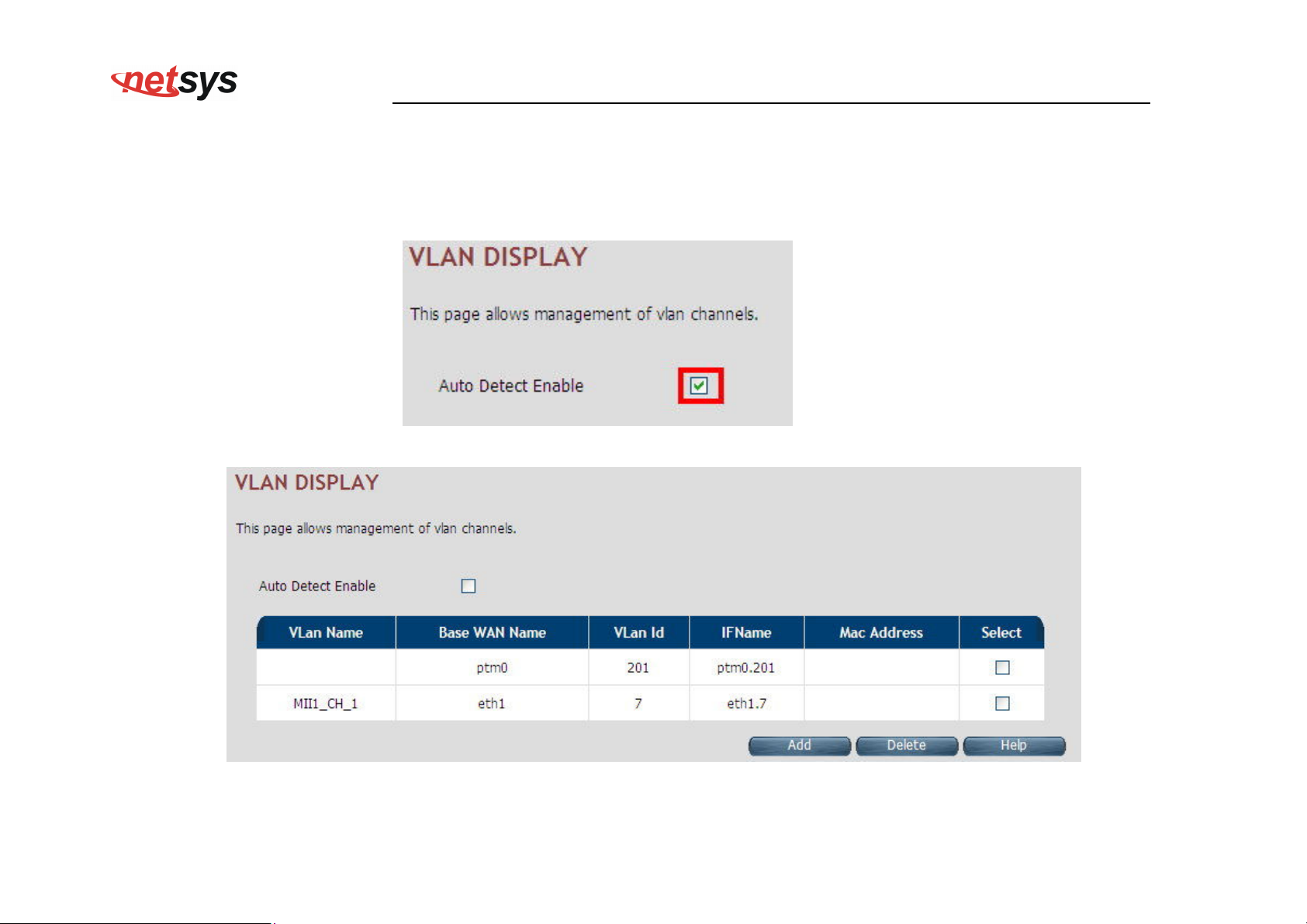
NV-600WI Managed Industrial Grade Wireless VDSL2 Router USER’S MANUAL Ver. A2
4.6.4 VLAN Channel Configuration
For configuring the VLAN Channel Configuration, click the VLAN Channel Config (WAN > VLAN Channel Config) on the
left navigation bar. A screen is displayed as shown in Figure 4.6.4.
Figure 4.6.4
Figure 4.6.4.1 VLAN Channel Configuration Display (Auto Detecting does not check the checkbox)
80
Page 82
NV-600WI Managed Industrial Grade Wireless VDSL2 Router USER’S MANUAL Ver. A2
The screen contains the following details:
Fields in VLAN Display:
Field Description
Auto Detect Enable To enable Auto Detect.
VLAN Name User specified VLAN Channel name.
Base WAN Name Displays the L2 interface names over which VLAN Channel has been configured.
VLAN id
VLAN identifier in range of 7- 4095. VLAN Identifiers (1 - 6) are internally used in
system for special purpose and are not available to user for configuration.
IF Name VLAN interface name.
MAC Address MAC address of VLAN interface name.
Select Select this option to delete a specific VLAN channel.
Click Add to save the information that you have entered.
Click Cancel to exit from this page without saving the changes.
When you click Add button inside the VLAN Channel Configuration page, a screen is displayed as shown in Figure 4.6.4.2
81
Page 83
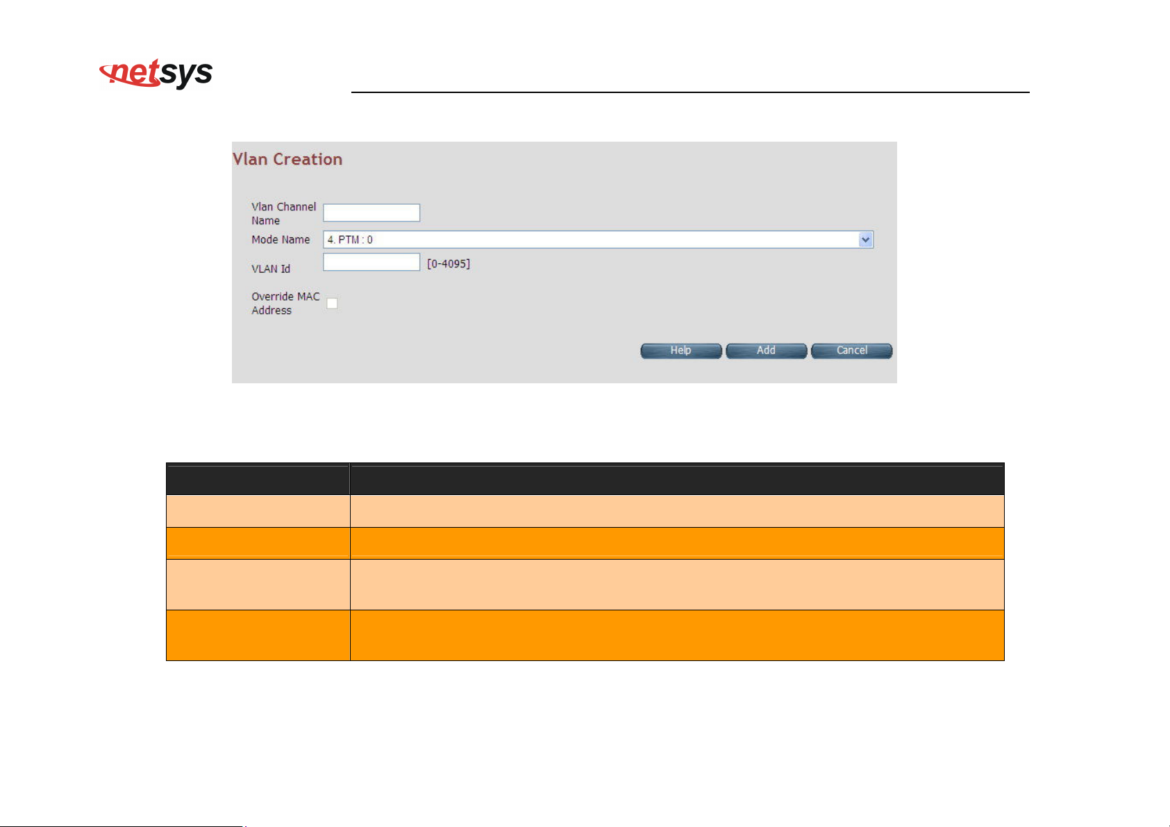
NV-600WI Managed Industrial Grade Wireless VDSL2 Router USER’S MANUAL Ver. A2
Figure 4.6.4.2 VLAN Channel Configuration - Add
The screen contains the following details:
Fields in VLAN Creation:
Field Description
VLAN Channel Name User specified VLAN Channel name.
Mode Name List of L2 interfaces over which VLAN Channels can be configured.
VLAN identifier in range of (7 - 4095). VLAN Identifiers (1 - 6) are internally used in
VLAN Id
system for special purpose and are not available to user for configuration.
Override MAC
Address
This is an option to configure MAC address by overriding physical MAC address. In
the current release, this option is not available to user for configuration.
Click Add to save the information that you have entered.
Click Cancel to exit from this page without saving the changes.
82
Page 84
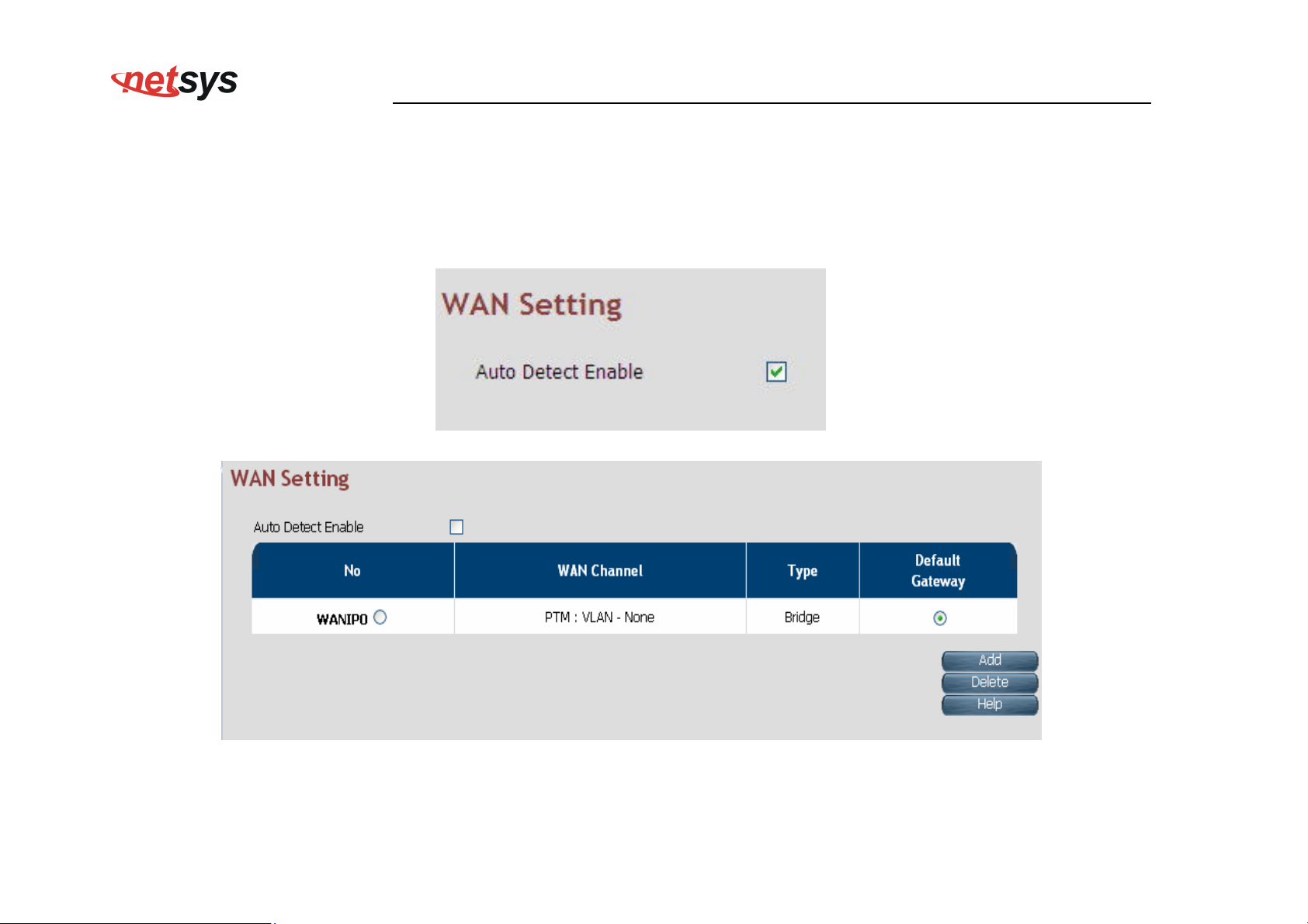
NV-600WI Managed Industrial Grade Wireless VDSL2 Router USER’S MANUAL Ver. A2
4.6.5 WAN Setting
For configuring the WAN interface, click the WAN Setting link (WAN > WAN Setting) on the left navigation bar and a screen is
displayed as shown in Figure 4.6.5.
Figure 4.6.5 WAN Setting - Auto Detect Enable
Figure 4.6.5.1 WAN Setting
83
Page 85
NV-600WI Managed Industrial Grade Wireless VDSL2 Router USER’S MANUAL Ver. A2
The NV-600WI can support up to a maximum of 16 WAN connections in system. When hardware based QoS is enabled in system, it
limits the number of VCCs to 8 only for ATM based WAN. For creating a new WAN connection, click Add in the WAN setting page.
Please follow the rest of the steps for creating the WAN connection.
The last column named DEFAULT GATEWAY allows selecting the WAN for relevant WAN mode setting in WAN setting web page.
When the user clicks any of the radio buttons, he will be asked to confirm the same. If the user clicks Apply, the default gateway will
be configured on the selected WAN connection; otherwise the changes will not be applied.
The screen contains the following details:
Fields in WAN Settings:
Field Description
Auto Detect Enable To enable Auto Detect.
WAN Number
The configured WAN are referred through auto-assigned names in form
WANIP<No.> or WANPPP<No.> where <No.> start from 0.
WAN Channel Provides information of layer-2 WAN channel configured.
Type Provides information about type of WAN such as PPPoE or DHCP or Bridged etc.
This option is present only in IAD models, where VoIP is supported. This is the
Default VoIP Interface
default interface for VoIP packets.
This option allows configuring default route in system. The chosen WAN will be
Default Gateway
used for default route.
When you click Add button in WAN Settings web page, a screen is displayed as shown in Figure 4.6.5.2
84
Page 86
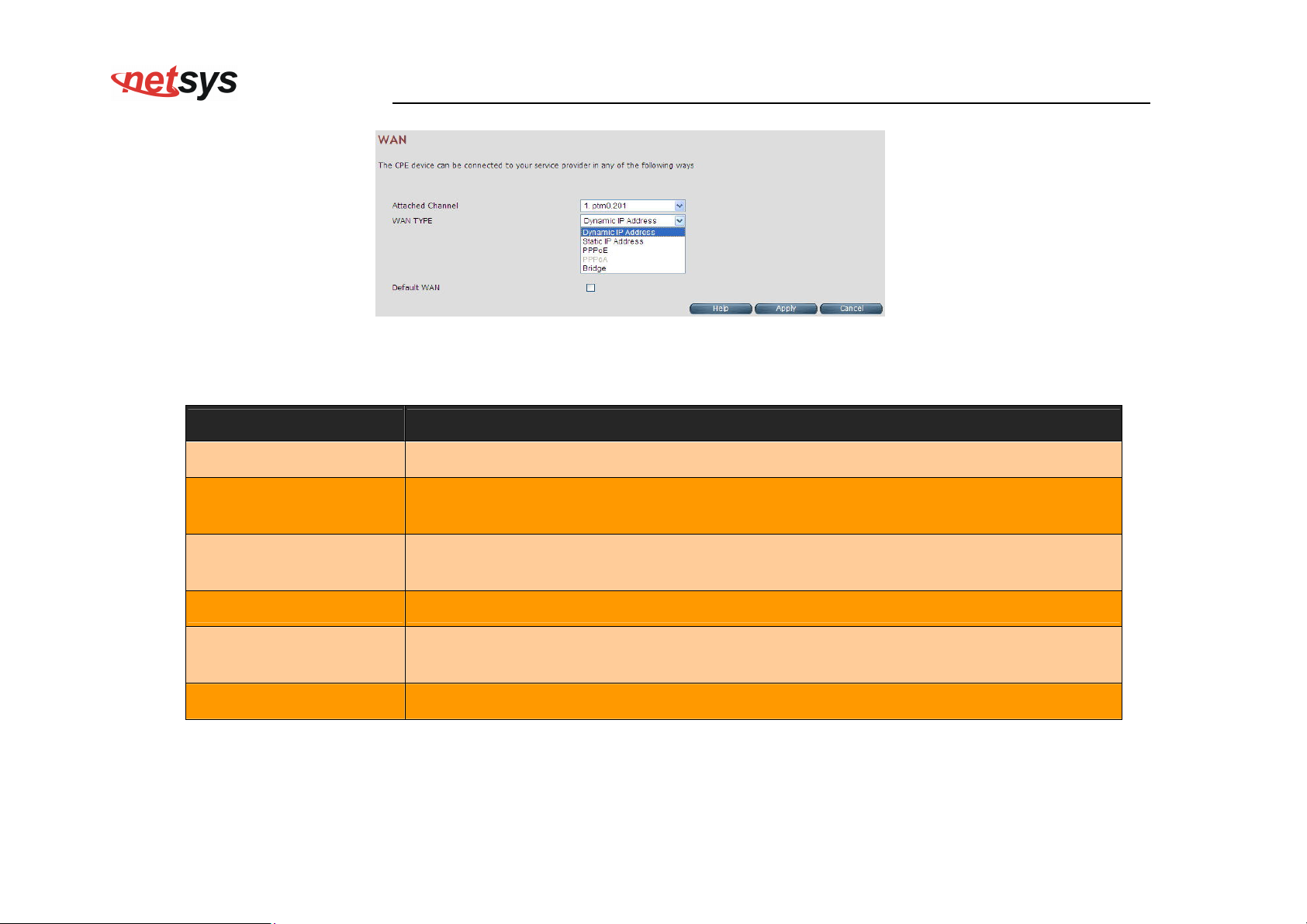
NV-600WI Managed Industrial Grade Wireless VDSL2 Router USER’S MANUAL Ver. A2
Figure 4.6.5.2 WAN Settings – Apply – Step1
The screen contains the following details:
Fields in WAN Settings – Apply – Step1:
Field Description
Attached Channel Select the WAN Channel (e.g. PVC) from drop-down, being configured as WAN.
Dynamic IP Address
To get your IP Address from your service provider (means NV-600WI is DHCP client
on WAN) click Apply.
To enter the WAN interface IP Address of NV-600WI enable this field and click
Static IP Address
Apply.
PPPoE
Point-to-Point Protocol over Ethernet used for connecting to the ISP, click Apply.
Point-to-Point Protocol over ATM used for connecting to the ISP, click Apply. This
PPPoA
setting is applicable only for ATM WAN mode.
Bridge
To configure the WAN of bridged type, select this field and click Apply.
Click Apply at any time during configuration to save the information that you have entered.
Click Cancel to exit from this page without saving the changes.
85
Page 87
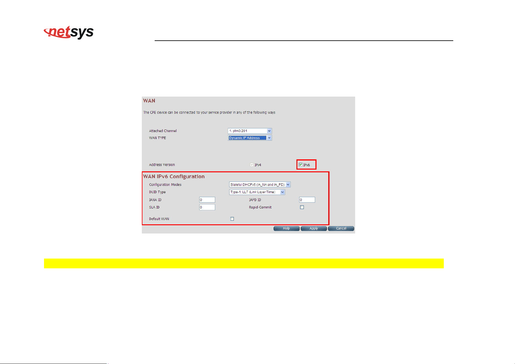
4.6.5.1 Dynamic IP Address
To configure the WAN interface of DHCP IP type, select Dynamic IP Address option. A screen is displayed as shown in
Figure 4.6.5.3
NV-600WI Managed Industrial Grade Wireless VDSL2 Router USER’S MANUAL Ver. A2
Figure 4.6.5.3 Dynamic IP Address
Please Enable IPv6 to set the WAN IPv6 Configuration. Select IPv6 Setting (IPv6 > IPv6 setting) on the left navigation bar.
86
Page 88
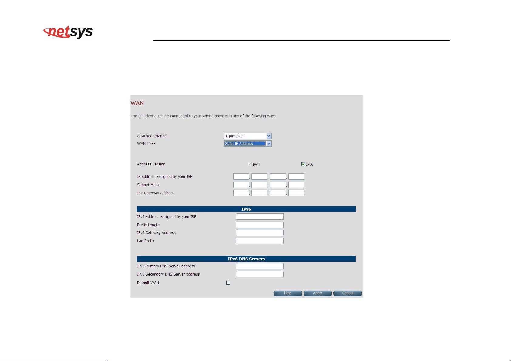
NV-600WI Managed Industrial Grade Wireless VDSL2 Router USER’S MANUAL Ver. A2
4.6.5.2 Static IP Address
To configure the WAN interface to use a static IP address, select the option Static IP Address in the WAN Settings screen. A
screen is displayed as shown in Figure 4.6.5.4
Figure 4.6.5.4 WAN Static IP
87
Page 89
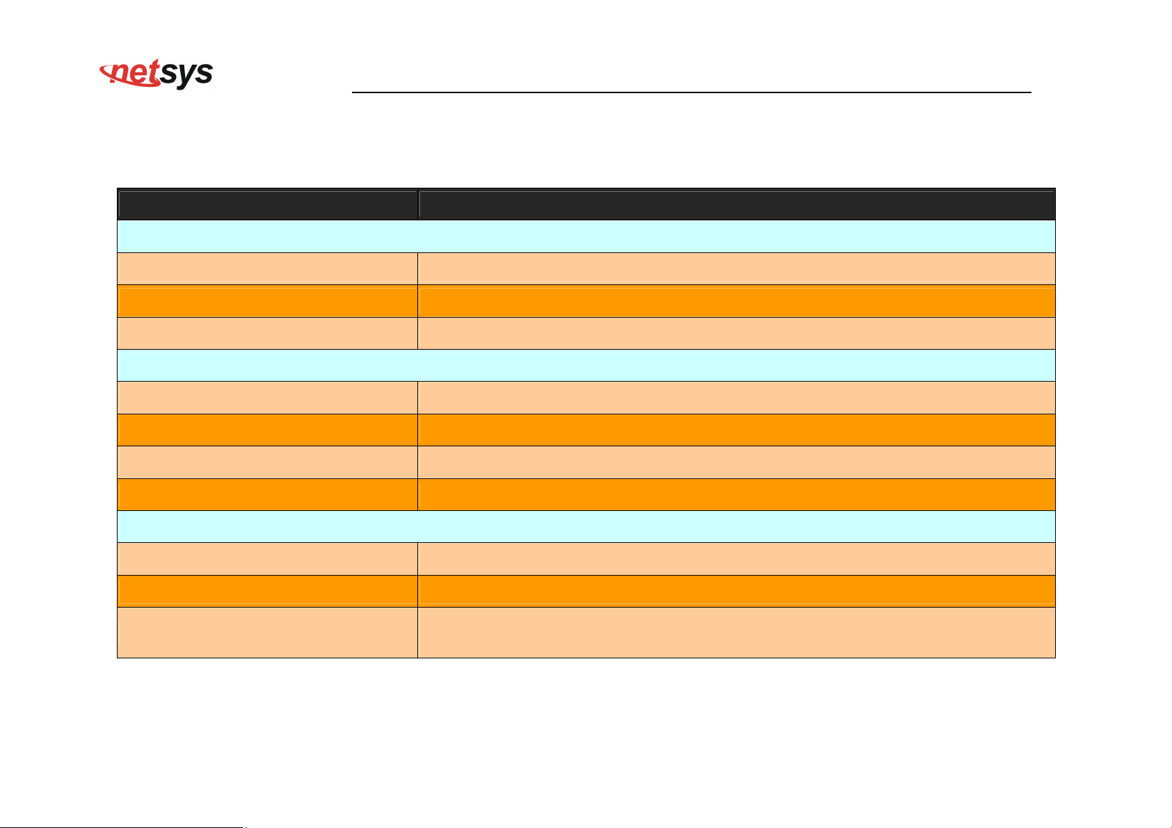
NV-600WI Managed Industrial Grade Wireless VDSL2 Router USER’S MANUAL Ver. A2
The screen contains the following details:
Fields in Static IP:
Field Description
Address Version
IP address assigned by your ISP To specify the IP Address of NV-600WI CPE’s WAN link.
Subnet Mask To specify the Subnet Mask of NV-600WI CPE’s WAN link.
ISP Gateway Address To specify the Gateway address of the NV-600WI CPE’s WAN.
IPv6
IPv6 address assigned by your ISP This is the static IP address for the WAN interface.
Prefix Length This is the prefix length of the IPv6 address.
IPv6 Gateway Address This is the default gateway.
LAN Prefix This is the prefix used to auto-configure LAN side hosts.
IPv6 DNS Servers
IPv6 Primary DNS Server Address This is the primary DNS server.
IPv6 Secondary DNS Server Address This is the secondary DNS server.
This option allows configuring default route for relevant WAN mode of this WAN
Default WAN
connection.
Click Apply at any time during configuration to save the information that you have entered.
Click Cancel to exit from this page without saving the changes.
88
Page 90
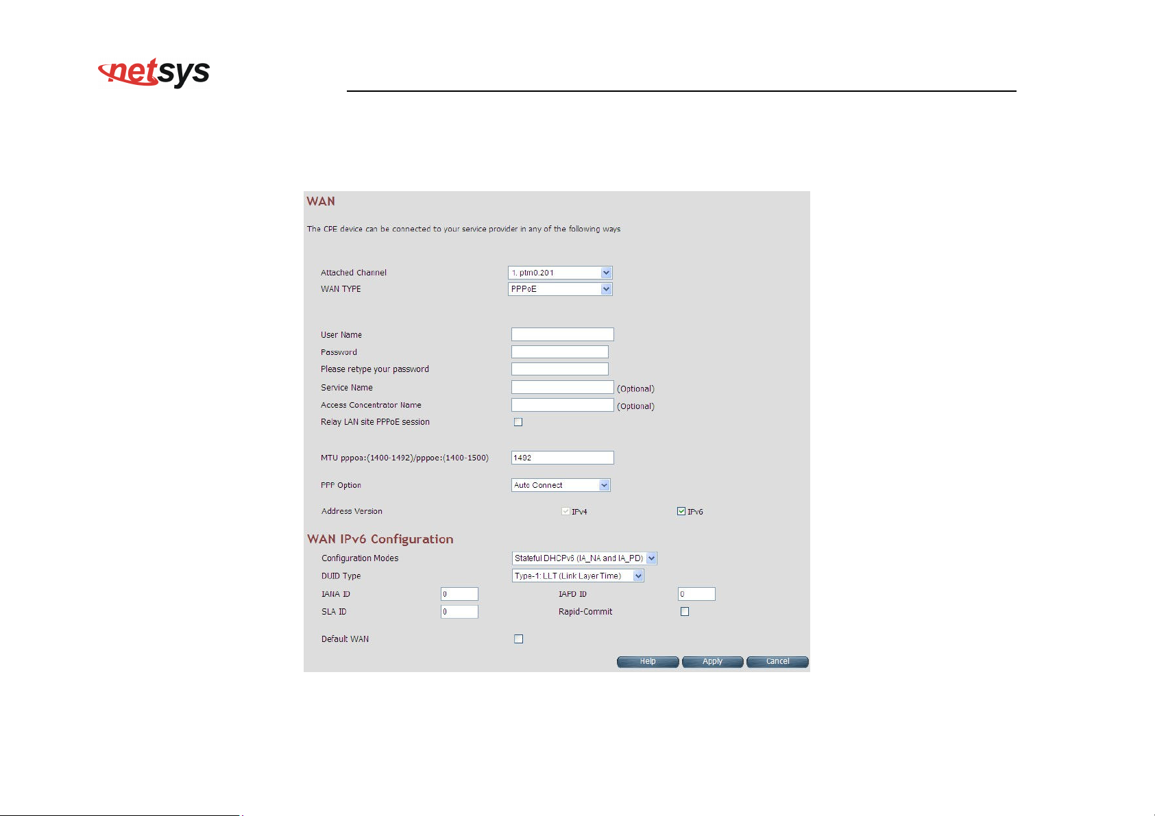
NV-600WI Managed Industrial Grade Wireless VDSL2 Router USER’S MANUAL Ver. A2
4.6.5.3 PPPoE
To configure the WAN interface to use PPPoE, choose the option PPPoE. A screen is displayed as shown in Figure 4.6.5.5
Figure 4.6.5.5 WAN PPPoE creation
89
Page 91
NV-600WI Managed Industrial Grade Wireless VDSL2 Router USER’S MANUAL Ver. A2
The screen contains the following details:
Fields in PPPoE WAN:
Field Description
User Name To enter a username for PPPoE session used for authentication in B-RAS.
Password To enter a password for PPPoE session used for authentication in B-RAS.
Please retype your password To enter the same password again to reconfirm.
Service Name PPP Service Name (optional).
Access Concentrator Name PPP Access concentrator Name (optional).
Relay LAN site PPPoE Session
This feature allows enable/disable a PPPoE relay session. PPPoE relay also called
PPPoE Passthrough.
Choose the option form the drop down list. The available options are, Auto Connect,
PPP Option
Dial-On-Demand and Manual Connect.
Address Version This option allows configurability of IPv4 and/or IPv6 stack on per WAN interface.
90
Page 92
Fields in PPPoE WAN (WAN IPv6 Configuration):
Field Description
This option allows to select following modes of IPv6 configuration:
NV-600WI Managed Industrial Grade Wireless VDSL2 Router USER’S MANUAL Ver. A2
Configuration Modes
DUID Type
IANA ID
IAPD ID
SLA ID
Rapid-commit
Stateful DHCPv6(IA_NA and IA_PD)
SLAAC (Address Configuration) with DHCPv6 (IA_PD)
This option allows to configure different DUID (DHCP Unique Identifier) types:
"Type-1: LLT (Link Layer Time)
"Type-2: EN (Enterprise Number)
"Type-3: LL (Link Layer)
IANA option represents IPv6 address and parameters related to the same being accepted by
DHCPv6 clients. IANA is the Identity Association for Non- Temporary Addresses option. This
Identifier has to be configured when Stateful DHCPv6 configuration mode is selected.
IAPD options represent one or more IPv6 prefix and parameters related to it. IAPD is the Identity
Association for Prefix Delegation. This identifier needs to be configured in both Stateful DHCPv6
and SLAAC+DHCPv6 configuration modes.
This parameter is called Site Level Aggregation Identifier. This identifier is used to configure the
subnet for DHCPv6 client configuration.
This declaration enables DHCPv6-client to request the DHCPv-server to perform a Rapid
Commit. Handshaking will happen with two DHCPv6 messages.
Default WAN This option allows configuring default route for relevant WAN mode of this WAN connection.
Click Apply at any time during configuration to save the information that you have entered.
Click Cancel to exit from this page without saving the changes.
91
Page 93
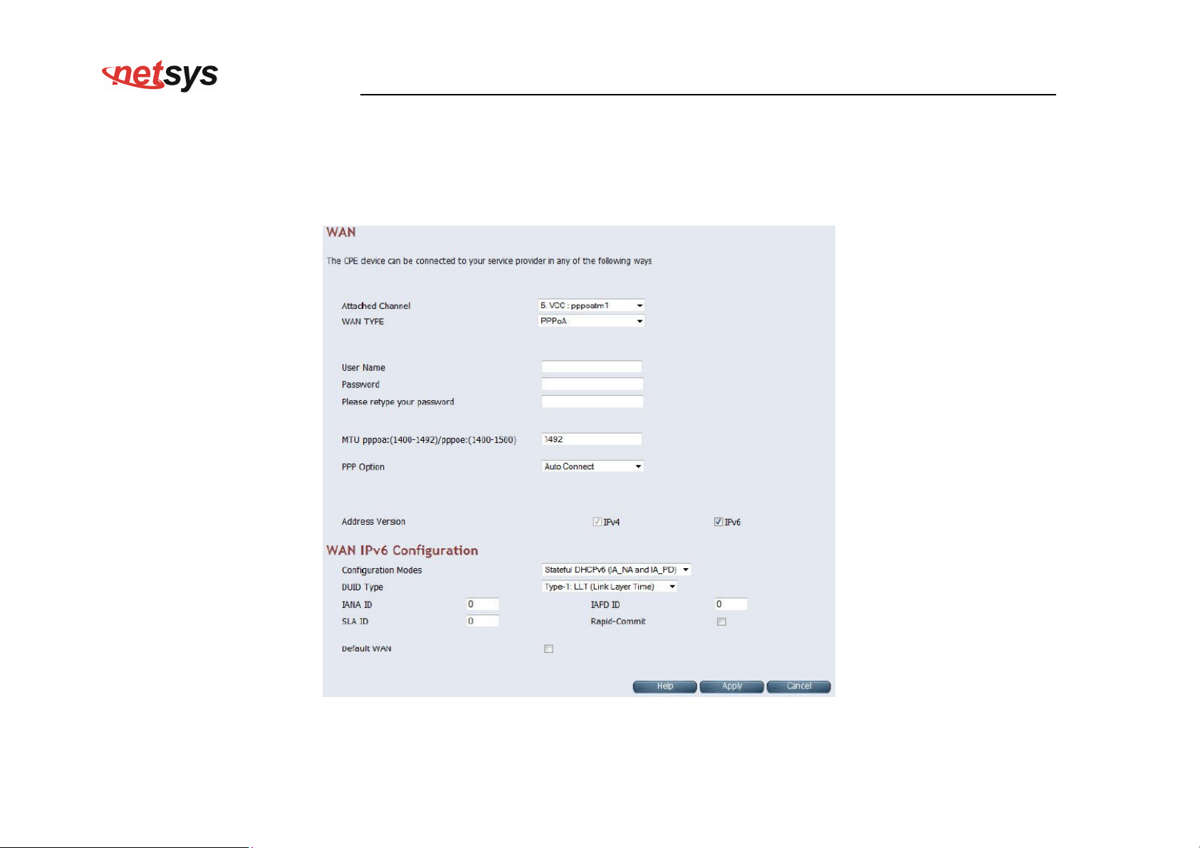
NV-600WI Managed Industrial Grade Wireless VDSL2 Router USER’S MANUAL Ver. A2
4.6.5.4 PPPoA
The PPP-over-ATM (PPPoA) mode is valid only for ATM based WAN. To configure the WAN interface to use PPPoA, select
the option PPPoA option. A screen is displayed as shown in Figure 4.6.5.6
Figure 4.6.5.6 WAN PPPoA creation
92
Page 94
NV-600WI Managed Industrial Grade Wireless VDSL2 Router USER’S MANUAL Ver. A2
The screen contains the following details:
Fields in PPPoA WAN:
Field Description
User Name To enter the username to be used in the PPPoA session.
Password To enter the corresponding password for the specified username.
Please retype your password To enter the password again to reconfirm.
Dial on Demand
Maximum Idle Time
Address Version
This feature allows the device to automatically re-connect to the service provider if
the connection is lost. The checkbox can be enabled or disabled for this feature.
Specifies how long the connection may remain idle before the PPPoA connection
gets automatically disconnected. The Idle Timeout is specified in seconds.
For PPPoA, the only supported IP addressing is IPv4 currently. The IPv6 for PPPoA
is not available in this version of NV-600WI.
93
Page 95
Fields in PPPoA WAN IPv6 Configuration:
Field Description
This option allows to select following modes of IPv6 configuration:
NV-600WI Managed Industrial Grade Wireless VDSL2 Router USER’S MANUAL Ver. A2
Configuration Modes
DUID Type
IANA ID
IAPD ID
SLA ID
Rapid-commit
Stateful DHCPv6(IA_NA and IA_PD)
SLAAC (Address Configuration) with DHCPv6 (IA_PD)
This option allows to configure different DUID (DHCP Unique Identifier) types:
"Type-1: LLT (Link Layer Time)
"Type-2: EN (Enterprise Number)
"Type-3: LL (Link Layer)
IANA option represents IPv6 address and parameters related to the same being accepted by
DHCPv6 clients. IANA is the Identity Association for Non- Temporary Addresses option. This
Identifier has to be configured when Stateful DHCPv6 configuration mode is selected.
IAPD options represent one or more IPv6 prefix and parameters related to it. IAPD is the
Identity Association for Prefix Delegation. This identifier to be configured in both Stateful
DHCPv6 or SLAAC+DHCPv6 configuration modes.
This parameter is called Site Level Aggregation Identifier. This identifier is used to configure
the subnet for DHCPv6 client configuration.
This declaration enables DHCPv6-client to request the DHCPv-server to perform a Rapid
Commit. Handshaking will happen with two DHCPv6 messages.
Default WAN This option allows configuring default route for relevant WAN mode of this WAN connection.
Click Apply at any time during configuration to save the information that you have entered.
94
Page 96
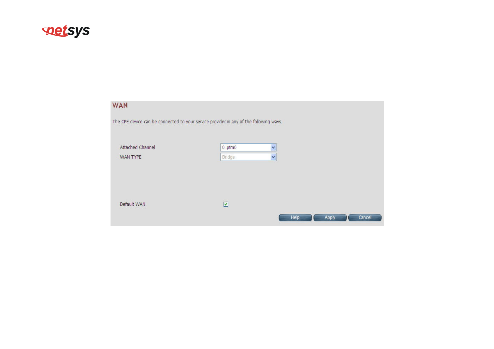
NV-600WI Managed Industrial Grade Wireless VDSL2 Router USER’S MANUAL Ver. A2
Click Cancel to exit from this page without saving the changes.
4.6.5.5 Bridge
The option Bridge enables the bridge mode, which is a common connection method used for xDSL modem. Select this option on
WAN Settings page and click Apply. A screen is displayed as shown in Figure 4.6.5.7
Figure 4.6.5.7 Bridge WAN Setting
The screen contains the following details:
95
Page 97
NV-600WI Managed Industrial Grade Wireless VDSL2 Router USER’S MANUAL Ver. A2
Fields in Bridge Configuration:
Field Description
Default WAN
This option allows configuring default route for relevant WAN mode of this WAN
connection.
Click Apply at any time during configuration to save the information that you have entered.
Click Cancel to exit from this page without saving the changes.
4.6.5.6 Delete
This option allows deleting the selected configured WAN connection. This makes WAN connections free to re-choose the type of
protocol and other parameters configuration.
Click Cancel to exit from this page without saving the changes.
Click Apply for deleting the WAN connection.
96
Page 98
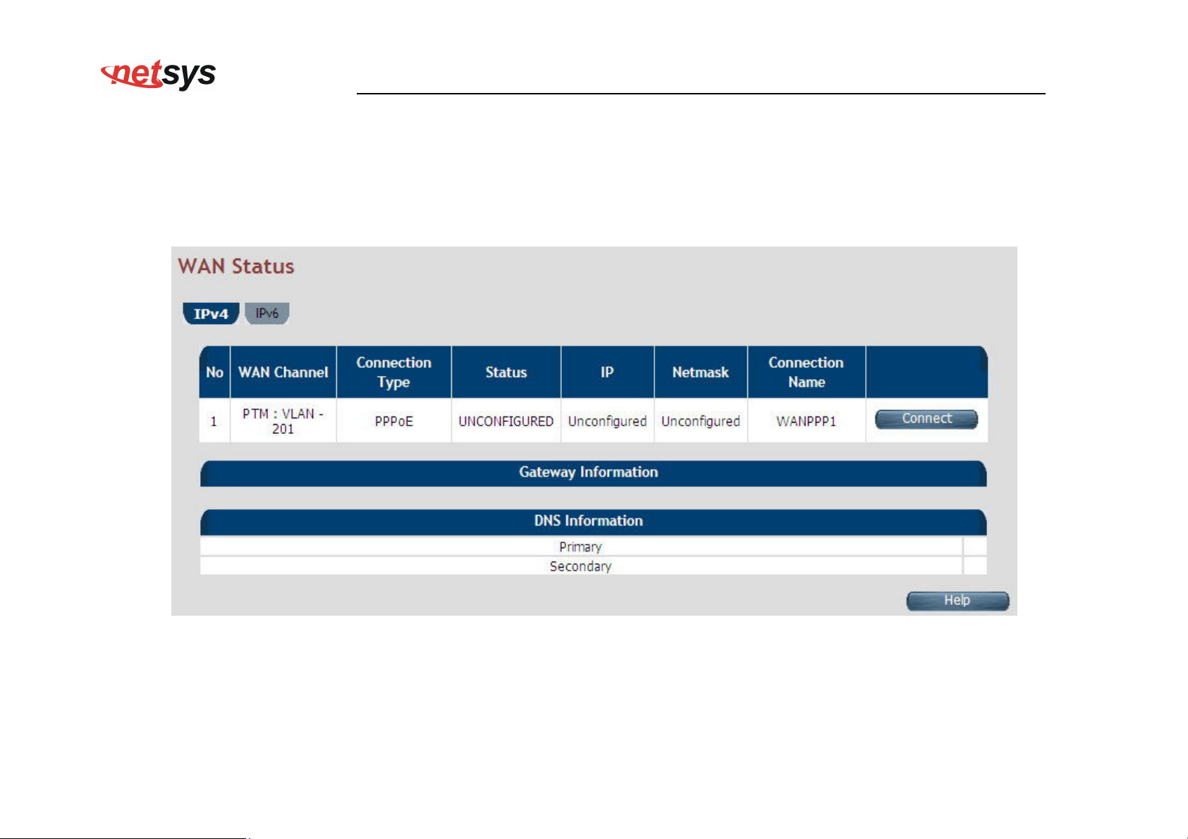
NV-600WI Managed Industrial Grade Wireless VDSL2 Router USER’S MANUAL Ver. A2
4.6.6 WAN Status
For displaying the status report of VCCs, click the WAN Status link (WAN > WAN Status) on the left navigation bar. A screen id
displayed as shown in Figure 4.6.6
Figure 4.6.6 WAN Status
97
Page 99
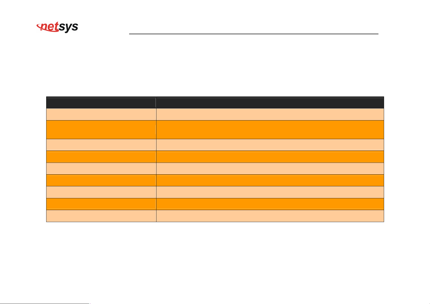
NV-600WI Managed Industrial Grade Wireless VDSL2 Router USER’S MANUAL Ver. A2
The screen contains the following details:
Fields in WAN Status:
Field Description
IPv4/IPv6 Choose the appropriate tab to view the status.
WAN Channel
For the currently configured WAN interface, this gives the layer-2 WAN channel
information (such as ATM VCC). VCC is virtual channel connection.
Connection Type The type of the connection mode in which NV-600WI is configured.
Status Displays the connection status of the WAN.
IP Displays the IP address in use.
Netmask Displays the netmask in use.
Configured Connection Name Displays the configured connection name.
Gateway Information Provides information about the gateway.
DNS Information Provides information about the primary and secondary DNS.
98
Page 100
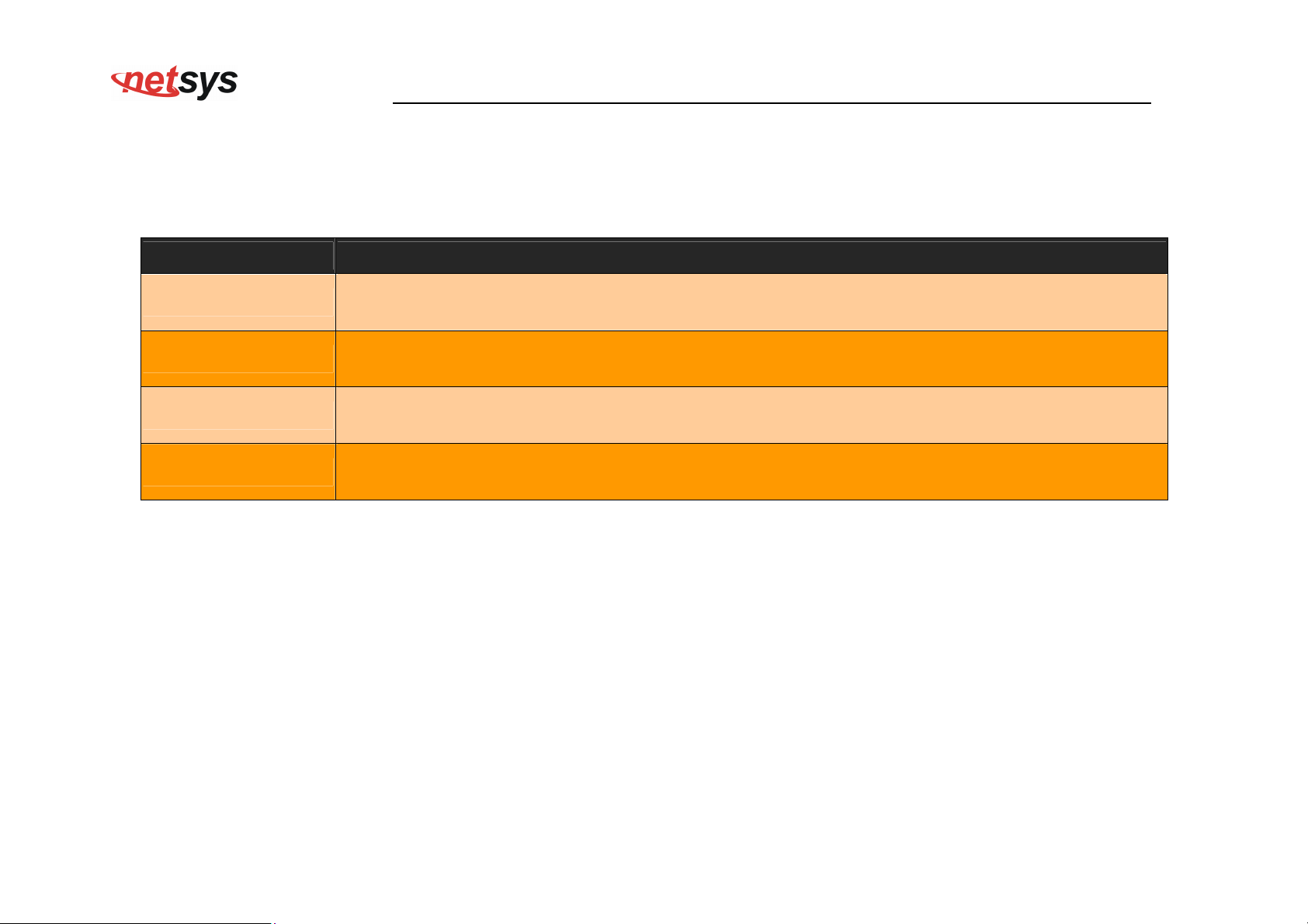
NV-600WI Managed Industrial Grade Wireless VDSL2 Router USER’S MANUAL Ver. A2
The control buttons shown against few WAN are explained below.
Fields in Control Fields displayed in WAN Status Screen:
Field Description
Connect
This button appears only for PPPoA and PPPoE type of WAN links. On clicking this button, it tries
to establish PPP link.
This button appears only for PPPoA and PPPoE type of WAN links. On clicking this button, it
Disconnect
brings down the PPP link.
This button appears only for DHCP type of WAN links. On clicking this button, it tries to establish
Renew
renew the current lease.
This button appears only for DHCP type of WAN links. On clicking this button, it tries to release the
Release
current lease.
When you click on the IPv6 tab in the WAN Status page, a screen is displayed as shown in Figure 4.6.6.1
99
 Loading...