

Page 1
NV-600L/R
VDSL2 CO/CPE Router
USER’S MANUAL
Page 2

NV600L/R VDSL2 CO&CPE Router USER’S MANUAL Ver.A15
1
Copyright
Copyright © 2010 by National Enhance Technology Corp. All rights reserved.
Trademarks
NETSYS is a trademark of National Enhance Technology Corp.
Other brand and product names are registered trademarks or trademarks of their respective holders.
Legal Disclaimer
The information given in this document shall in no event be regarded as a guarantee of conditions or characteristics. With respect to any examples or hints
given herein, any typical values stated herein and/or any information regarding the application of the device, National Enhance Technology Corp. hereby
disclaims any and all warranties and liabilities of any kind, including without limitation warranties of non-infringement of intellectual property rights of any third
party.
Statement of Conditions
In the interest of improving internal design, operational function, and/or reliability, NETSYS reserves the right to make changes to the products described in
this document without notice. NETSYS does not assume any liability that may occur due to the use or application of the product(s) or circuit layout(s)
described herein.
Maximum signal rate derived form IEEE Standard specifications. Actual data throughput will vary. Network conditions and environmental factors, including
volume of network traffic, building materials and construction, and network overhead lower actual data throughput rate.
Page 3

NV600L/R VDSL2 CO&CPE Router USER’S MANUAL Ver.A15
2
VDSL2 Point to Point Solution
VDSL2 (Very-High-Bit-Rate Digital Subscriber Line 2, ITU-T G.993.2 Standard) is an access technology that exploits the existing
infrastructure of copper wires that were originally deployed for POTS services. It can be deployed from central offices, from
fibre-fed cabinets located near the customer premises, or within buildings.
ITU-T G.993.2 VDSL2 is the newest and most advanced standard of DSL broadband wireline communications. Designed to support
the wide deployment of Triple Play services such as voice, video, data, high definition television (HDTV) and interactive gaming,
VDSL2 enables operators and carriers to gradually, flexibly, and cost efficiently upgrade existing xDSL-infrastructure.
ITU-T G.993.2 (VDSL2) is an enhancement to G.993.1 VDSL that permits the transmission of asymmetric and symmetric
(Full-Duplex) aggregate data rates up to 200 Mbit/s on twisted pairs using a bandwidth up to 30 MHz.
VDSL2 deteriorates quickly from a theoretical maximum of 200 Mbit/s (Full-Duplex) at 'source' to 100 Mbit/s at 0.3 km (symmetric).
Page 4

NV600L/R VDSL2 CO&CPE Router USER’S MANUAL Ver.A15
3
Safety Warnings
For your safety, be sure to read and follow all warning notices and instructions before device use.
• DO NOT open the device or unit. Opening or removing covers can expose you to dangerous high voltage points or other risks.
ONLY qualified service personnel can service the device. Please contact your vendor for further information.
• Use ONLY the dedicated power supply for your device. Connect the power cord or power adaptor to the right supply voltage
(110V AC in North America or 230V AC in Europe).
• DO NOT use the device if the power supply is damaged as it might cause electrocution.
• If the power supply is damaged, remove it from the power outlet.
• DO NOT attempt to repair the power supply. Contact your local vendor to order a new power supply.
• Place connecting cables carefully so that no one will step on them or stumble over them. DO NOT allow anything to rest on the
power cord and do NOT locate the product where anyone can work on the power cord.
• DO NOT install nor use your device during a thouderstorm. There may be a remote risk of electric shock from lightning.
• DO NOT expose your device to dampness, dust or corrosive liquids.
• DO NOT use this product near water, for example, in a wet basement or near a swimming pool.
• Connect ONLY suitable accessories to the device.
• Make sure to connect the cables to the correct ports.
• DO NOT obstruct the device ventilation slots, as insufficient airflow may harm your device.
• DO NOT store things on the device.
• DO NOT use the device outside, and make sure all the commections are indoors. There may be a remote risk of electric shock
from lightning.
• Be careful when unplugging the power, because the transformer may be very hot.
• Keep the device and all its parts and accessories out of children’s reach.
• Clean the device using a soft and dry cloth rather than liquid or atomizers. Power off the equipment before cleansing it.
• This product is recyclable. Dispose of it properly.
Page 5

NV600L/R VDSL2 CO&CPE Router USER’S MANUAL Ver.A15
4
Table of Contents
Copyright.............................................................................................................................................................................................1
Safety Warnings..................................................................................................................................................................................3
Table of Contents................................................................................................................................................................................4
1.Unpacking Information....................................................................................................................................................................8
1.1 Check List....................................................................................................................................................................................8
2. Complete Installation .....................................................................................................................................................................9
2.1 Hardware Installation...................................................................................................................................................................9
2.2 Pre-installation Requirements......................................................................................................................................................9
2.3 General Rules............................................................................................................................................................................10
2.4 NV-600L/R Connections............................................................................................................................................................10
3. Hardware Description...................................................................................................................................................................12
3.1 Front Panel................................................................................................................................................................................12
3.2 Six LED indicators .....................................................................................................................................................................13
3.3 Front Indicators..........................................................................................................................................................................13
3.4 Rear Panel.................................................................................................................................................................................14
3.5 Power On...................................................................................................................................................................................14
4. Configure the NV-600L/R Via Web Browser................................................................................................................................15
4.1 Login..........................................................................................................................................................................................15
Page 6

NV600L/R VDSL2 CO&CPE Router USER’S MANUAL Ver.A15
5
4.2 Select the Menu Level...............................................................................................................................................................16
4.3 Select Advanced Setup..............................................................................................................................................................18
4.4 Select LAN.................................................................................................................................................................................20
4.4.1 Select LAN Settings and set the IP Address.....................................................................................................................21
4.4.2 Restart the Settings Dialog...............................................................................................................................................23
5. Configure the NV-600L/R via Console.........................................................................................................................................24
5.1 Setup on Hyperterminal.............................................................................................................................................................24
5.2 Reset the system to default configuration..................................................................................................................................24
6. Building a VDSL2 System............................................................................................................................................................25
6.1 Connect the NV-600L and the NV-600R to the Line ..................................................................................................................26
6.2 Connect the NV-600L and the NV-600R to LAN Devices ..........................................................................................................26
6.3 Run Demos and Tests ...............................................................................................................................................................26
7. Operating the VDSL2 System......................................................................................................................................................27
7.1 Configuration Settings ...............................................................................................................................................................27
7.1.1 Channel Configuration......................................................................................................................................................28
7.1.2 Line Configuration.............................................................................................................................................................31
7.1.3 Profile Configuration.........................................................................................................................................................32
7.1.4 Loop Back.......................................................................................................................................................................399
7.1.5 Line Activation...................................................................................................................................................................40
7.2 Status Displays..........................................................................................................................................................................41
7.2.1 Line Status........................................................................................................................................................................41
7.2.2 Channel Status.................................................................................................................................................................42
7.2.3 Version Info.......................................................................................................................................................................43
7.2.4 SNR Graphs .....................................................................................................................................................................44
7.2.5 BitsGraphs........................................................................................................................................................................46
Page 7

NV600L/R VDSL2 CO&CPE Router USER’S MANUAL Ver.A15
6
8. Configuration Interface of the Router.........................................................................................................................................47
8.1 Logging in to the NV-600L/R......................................................................................................................................................48
8.2 Setup Wizard and Advanced Setup...........................................................................................................................................49
8.2.1 Setup Wizard....................................................................................................................................................................50
8.2.2 Advanced Setup................................................................................................................................................................51
8.2.3 System..............................................................................................................................................................................53
8.2.3.1 Administrator Settings....................................................................................................................................................54
8.2.3.2 Firmware Upgrade.........................................................................................................................................................56
8.2.3.3 Device Mode..................................................................................................................................................................57
8.2.3.4 System Status................................................................................................................................................................58
8.2.3.5 Reboot...........................................................................................................................................................................59
8.2.3.6 Reset system.................................................................................................................................................................60
8.2.4 WAN.................................................................................................................................................................................61
8.2.4.1 Dynamic IP ....................................................................................................................................................................62
8.2.4.2 IP Settings .....................................................................................................................................................................63
8.2.4.3 PPPoE...........................................................................................................................................................................65
8.2.4.4 DNS...............................................................................................................................................................................67
8.2.5 LAN...................................................................................................................................................................................69
8.2.5.1 LAN Settings..................................................................................................................................................................70
8.2.5.2 DHCP Client List............................................................................................................................................................72
8.2.5.3 LAN Switch Port Setting.................................................................................................................................................73
8.2.5.4 LAN Port Status.............................................................................................................................................................74
8.2.6 NAT...................................................................................................................................................................................75
8.2.6.1 Virtual Server.................................................................................................................................................................76
8.2.6.2 Port Mapping .................................................................................................................................................................78
8.2.6.3 DMZ...............................................................................................................................................................................80
8.2.7 Firewall.............................................................................................................................................................................81
8.2.7.1 Firewall Options.............................................................................................................................................................82
8.2.7.2 Client Filtering................................................................................................................................................................84
8.2.7.3 MAC Control..................................................................................................................................................................86
Page 8

NV600L/R VDSL2 CO&CPE Router USER’S MANUAL Ver.A15
7
8.2.8 Route Settings..................................................................................................................................................................88
8.2.8.1 Static Routing.................................................................................................................................................................89
8.2.8.2 Routing Table List..........................................................................................................................................................90
8.2.9 UPnP Setting....................................................................................................................................................................91
8.2.9.1 Settings..........................................................................................................................................................................92
Appendix A: Product Features & Specification.............................................................................................................................93
Features: .........................................................................................................................................................................................93
Specifications: .................................................................................................................................................................................94
Appendix B: Troubleshooting.........................................................................................................................................................96
Appendix C : Compliance and Safety Information.........................................................................................................................98
Warranty..........................................................................................................................................................................................101
Page 9

NV600L/R VDSL2 CO&CPE Router USER’S MANUAL Ver.A15
8
1.Unpacking Information
1.1 Check List
Carefully unpack the package and check its contents against the checklist.
Package Contents
VDSL2 Router (NV-600L for CO side/ NV-600R for CPE side)
Two rubber feet
User’s Manual
AC to DC 12V Power Adapter
RJ-45 cable
RJ-11 cable
Please inform your dealer immediately for any missing or damaged parts.
If possible, retain the carton including the original packing materials.
Use them to repack the unit in case there is a need to return for repair.
Page 10

NV600L/R VDSL2 CO&CPE Router USER’S MANUAL Ver.A15
9
2. Complete Installation
2.1 Hardware Installation
This chapter describes how to install the NV-600L/R and establishes network connections. This may install the
NV-600L/R on any level surface (e.g, a table or shelf). However, please take note of the following minimum site
requirements before you begin.
2.2 Pre-installation Requirements
Before the start actual hardware installation, make sure to provide the right operating environment, including power
requirements, sufficient physical space and proximity to other network devices that are to be connected. Verify the
following installation requirement:
• Power requirements: DC12V/1A or above.
• The NV-600L/R should be located in a cool dry place, with at least 10cm/4in of space at the front and back for
ventilation.
• Place the NV-600L/R out of direct sunlight, and away from heat sources or areas with a high amount of
electromagnetic interference.
• Check if network cables and connectors needed for installation are available
Page 11

NV600L/R VDSL2 CO&CPE Router USER’S MANUAL Ver.A15
10
2.3 General Rules
Before making any connections to the NV-600L/R, note the following rules:
• Ethernet Port (RJ-45)
All network connections to the Router Ethernet port must be made using Category 5 UTP for 100Mbps;
Category 3, 4 UTP for 10Mbps
No more than 100 meters of cabling may be use between the MUX or HUB and an end node.
• Phone Port (RJ-11)
All Phone set connections to the RJ-11 Port must use 24~26 Gauge phone wiring.
2.4 NV-600L/R Connections
The NV-600L/R can be controlled by a PC. For this purpose, a PC is needed with an Ethernet network interface and a
DB-9 RS-232 serial interface. Two programs are required: A Web browser is mandatory and a terminal program should
be available optionally.
The board has several connectors.
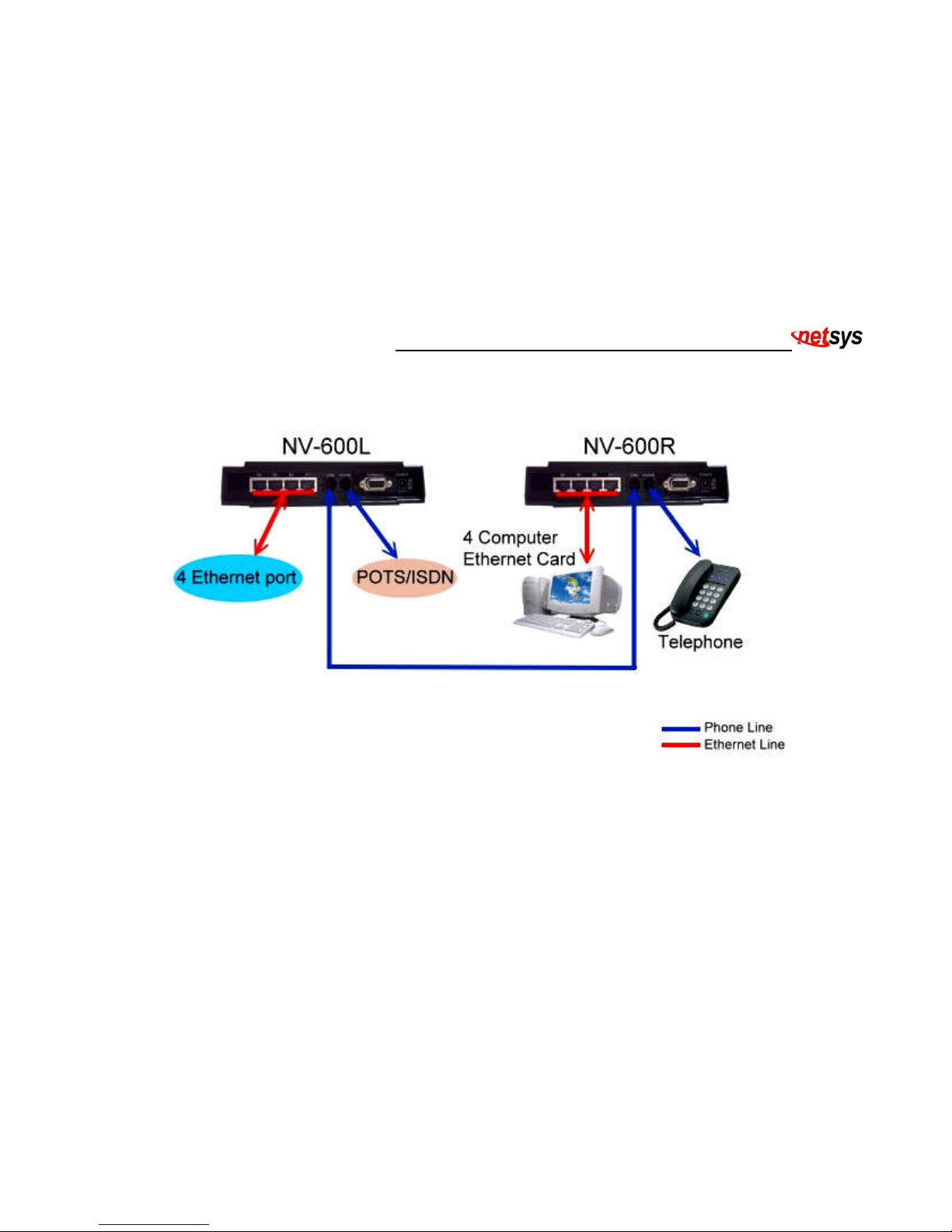
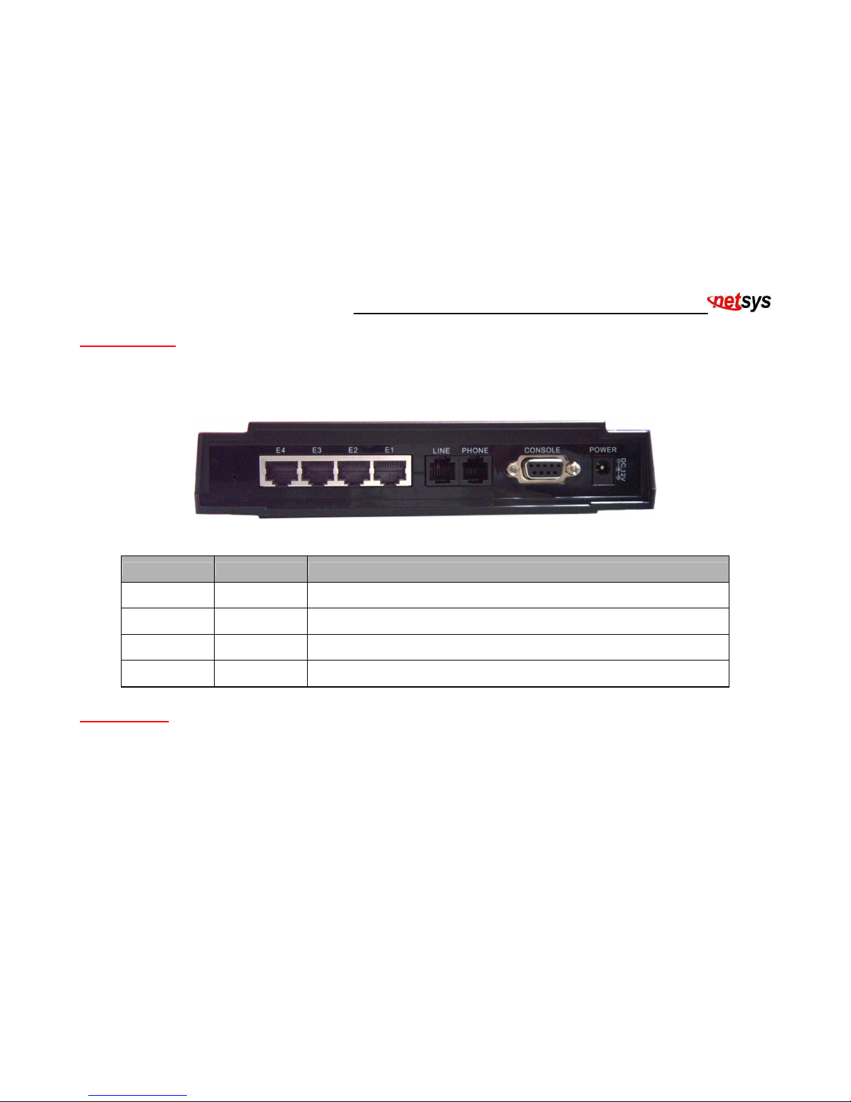
• 4 Ethernet RJ-45 jacks; the Auto MDIX feature of the port switches automatically between MDI and MDI-X
(MDI – X = Media Dependant Interface - Crossover). Therefore straight Ethernet cables can be used.
• 2 x RJ-11 jack (Line port is for VDSL client side connection to Line interface, Phone port is for connection to
phone set or FAX machine).
• 1 x Console port (access monitoring to operating system for firmware downloads, starting drivers and etc.)
• 1 Power Supply (as described above)
Page 12
NV600L/R VDSL2 CO&CPE Router USER’S MANUAL Ver.A15
11
Figure 2.4 VDSL2 Basic Setup
Page 13
NV600L/R VDSL2 CO&CPE Router USER’S MANUAL Ver.A15
12
3. Hardware Description
This section describes the important parts of the NV-600L/R. It features the front indicators and rear connectors.
3.1 Front Panel
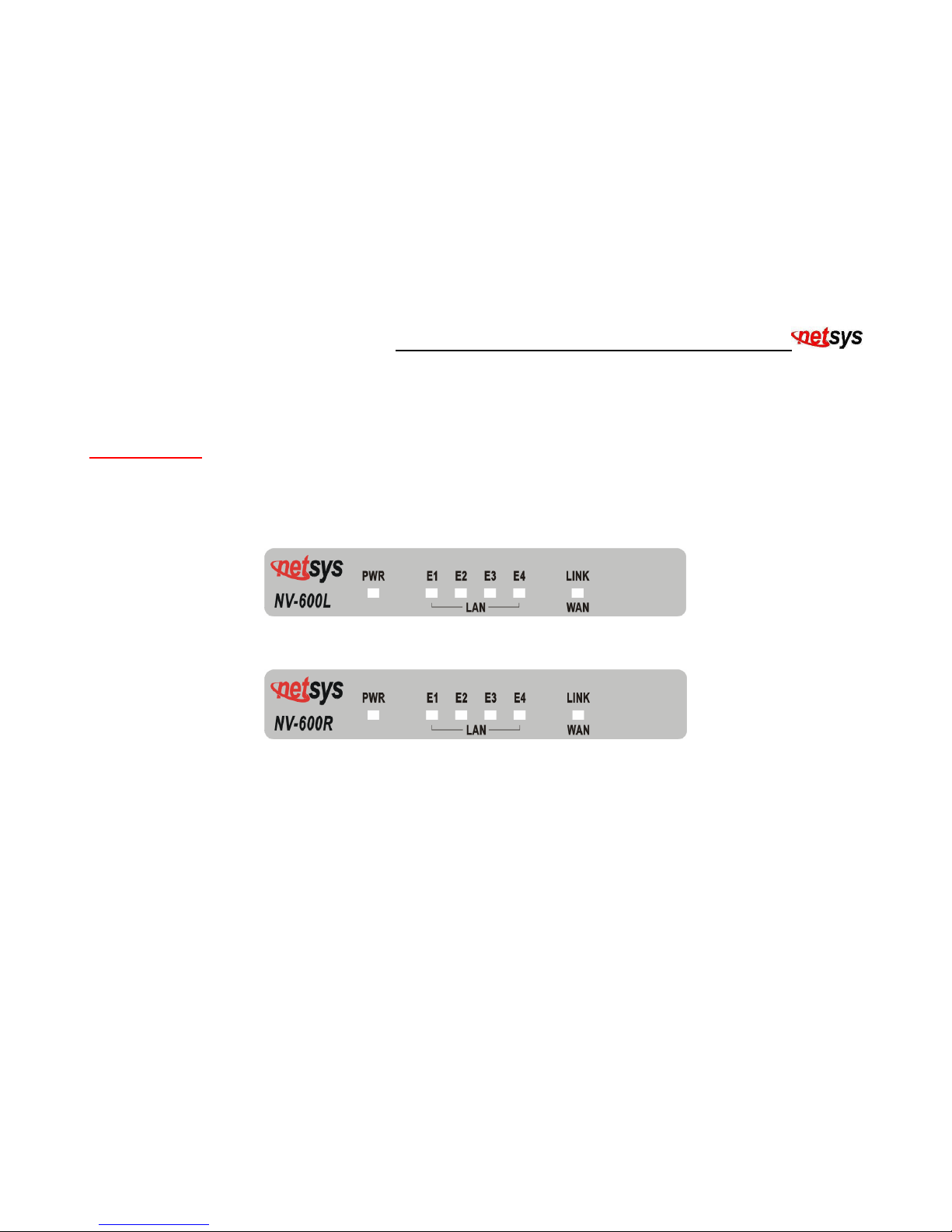
The following figure shows the front panel.
Figure 3.1.1 NV-600L
Figure 3.1.2 NV-600R
Page 14
NV600L/R VDSL2 CO&CPE Router USER’S MANUAL Ver.A15
13
3.2 Six LED indicators
At a quick glance of the front panel, it will be easy to tell if the router has power signal from its Ethernet RJ-45 port or there
is phone line signal RJ-11port
3.3 Front Indicators
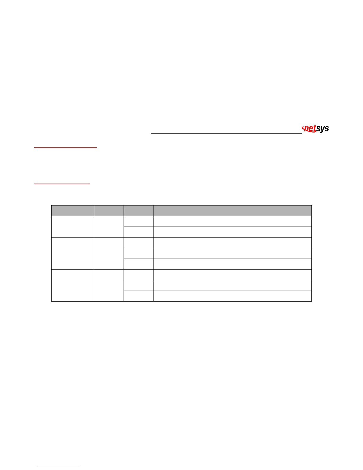
The following table describes the LEDs.
LEDs Color Status Descriptions
On The device is receiving the power and functioning properly.
PWR Green
Off The device is not ready or has malfunctioned.
On The device has a good Ethernet connection.
Blinking The device is sending or receiving data.
E1~E4
(LAN)
Green
Off The LAN is not connected.
On The Internet or network connection is up.
Blinking The device is sending or receiving data.
LINK / WAN Green
Off The Internet or network connection is down.
Page 15
NV600L/R VDSL2 CO&CPE Router USER’S MANUAL Ver.A15
14
3.4 Rear Panel
The following figure shows the rear connectors
Figure 3.4 Rear Connectors
NV-600L/R Rear Connectors
Connectors Type Description
Line RJ-11 For connecting to the VDSL2 Router Using a RJ-11 cable
Phone RJ-11 For connecting to the POTS equipment or ISDN router
E1~E4 RJ-45 For connecting to a Ethernet equipped device
Console RS-232 For connecting to PC with RS-232 serial port over a D-SUB Cable
3.5 Power On
Check the adapter is properly connected.
Verify the power LED is steadily on.
Page 16
NV600L/R VDSL2 CO&CPE Router USER’S MANUAL Ver.A15
15
4. Configure the NV-600L/R Via Web Browser
The NV-600L/R provides a built-in HTML based management interface that allow user configure the NV-600L/R via
Internet Browser. Recommend using Internet Explorer 6.0 or later version and set screen resolution at 1024 x 768.
In order to use the web browser configure the device, you may need to allow:
• Web browser pop-up windows from your device. Web pop-up blocking is enabled by default in windows XP SP2.
• JavaScripts. (Enabled by default)
• Java permissions. (Enabled by default)
Launch your web browser and input the IP address 192.168.16.249 (NV-600L) or 192.168.16.250 (NV-600R) in the Web
page.
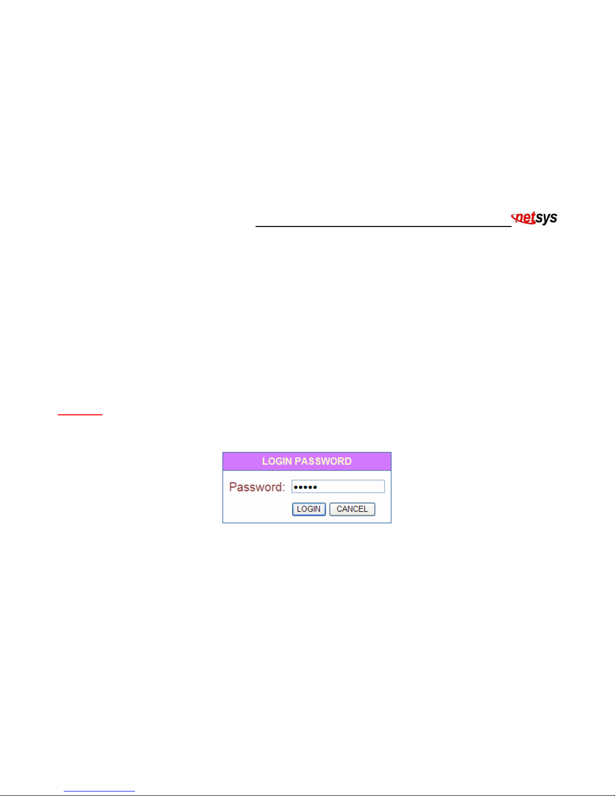
4.1 Login
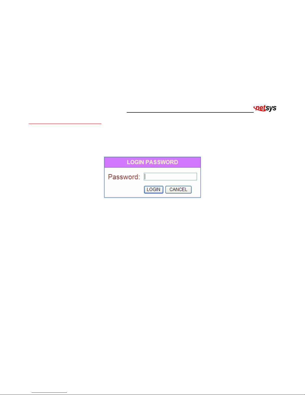
The default password is “admin“. The password is changeable in Administrator Settings.
Figure 4.1 Login Password
Page 17
NV600L/R VDSL2 CO&CPE Router USER’S MANUAL Ver.A15
16
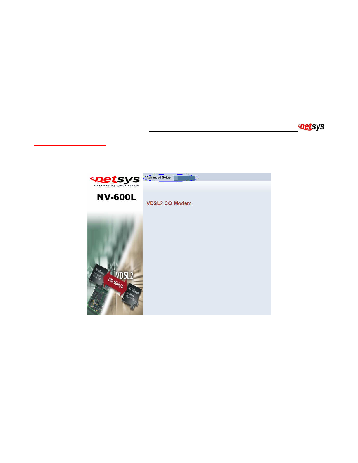
4.2 Select the Menu Level
There is an easy Setup Wizard for end users at the NV-600R and an Advanced Setup for more detail configurations. This
manual attaches importance to the Advanced Setup.
Page 18
NV600L/R VDSL2 CO&CPE Router USER’S MANUAL Ver.A15
17
Figure 4.2 Select the Advanced Setup in the Entry Screen
Page 19
NV600L/R VDSL2 CO&CPE Router USER’S MANUAL Ver.A15
18
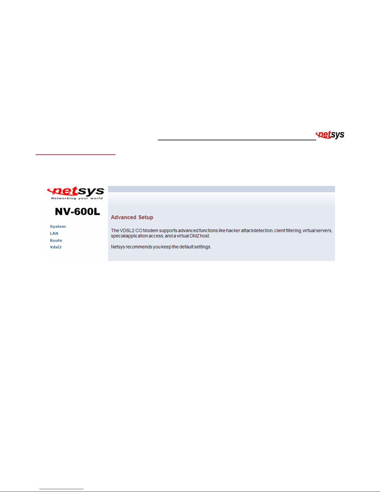
4.3 Select Advanced Setup
Select the Advanced Setup. The menu below will be used frequently. As an exercise and an example now the IP address
will be set.
Page 20
NV600L/R VDSL2 CO&CPE Router USER’S MANUAL Ver.A15
19
Figure 4.3 Advanced Setup
Attention: The settings in the following Chapter 4.4 only need to be performed in order to change LAN settings. Such a
change may be necessary when connecting the NV-600L/R to a new control PC and/or in order to turn the IP address
changed via a shell command into a default address for the next restart of the board.
Page 21
NV600L/R VDSL2 CO&CPE Router USER’S MANUAL Ver.A15
20
4.4 Select LAN
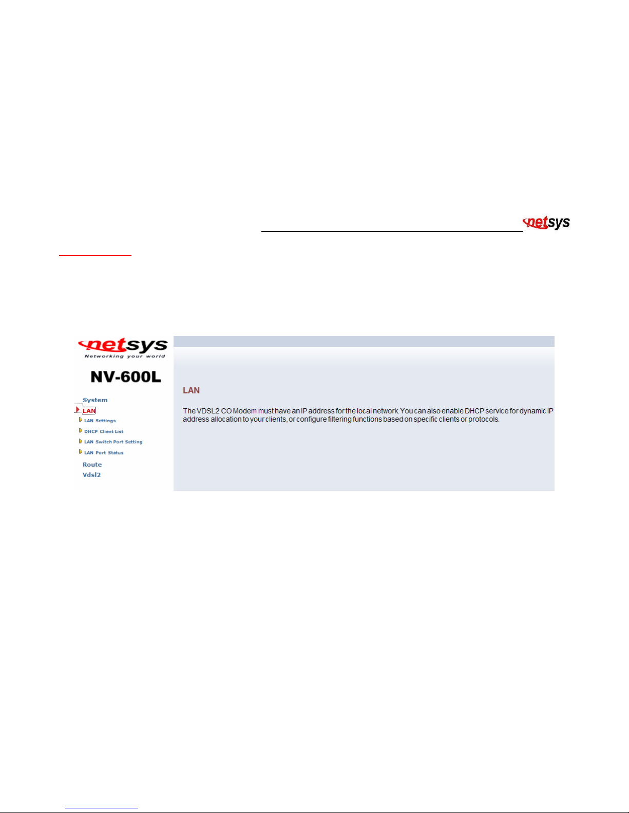
The menu below will not be used very often, but when connecting the NV-600L/R to a new control PC, one may want to
go through the following steps in order to make the IP address previously set by ifconfig in the console or on some later
occasion one may want to change it again without using the console then the menu below will be helpful. In order to set
the IP address, click on “LAN Settings”.
Figure 4.4 LAN menu
Page 22
NV600L/R VDSL2 CO&CPE Router USER’S MANUAL Ver.A15
21
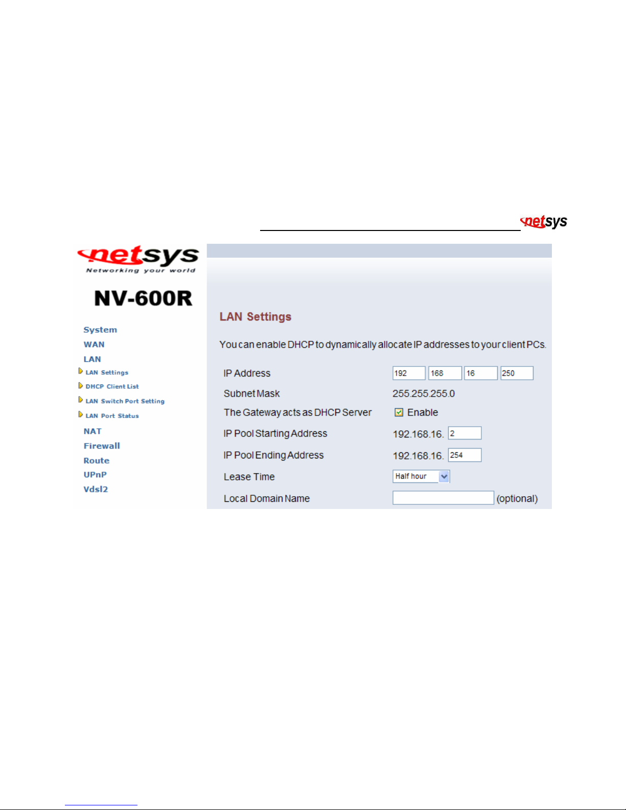
4.4.1 Select LAN Settings and set the IP Address
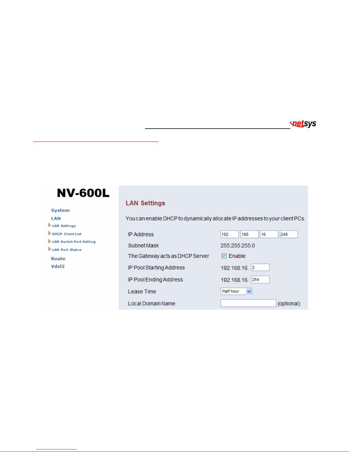
The form below is used to change the IP address of the LAN port “adm0” in the NV-600L/R.
The proposed IP address is either the default address of adm0 or it is the address changed by an ifconfig command via
the shell running in the terminal. The Subnet Mask display can be ignored. In case the DHCP checkbox is checked, some
additional data and options will be on display (see Chapter 8.2.5.1 on Page 70). The DHCP server is not required to work
with VDSL2 in a lab environment. It recommend to uncheck the box if it is not unchecked already.
Page 23
NV600L/R VDSL2 CO&CPE Router USER’S MANUAL Ver.A15
22
Figure 4.4.1 LAN Settings
Now the IP address either may be changed or left as it is. If it has been changed in the form or after it has been changed
through console ifconfig command, it needs to be “APPLY” in order to make the displayed IP address new default
address.
Page 24
NV600L/R VDSL2 CO&CPE Router USER’S MANUAL Ver.A15
23
4.4.2 Restart the Settings Dialog
After the “APPLY” button has been hit, the displayed IP address “adm0” port will be stored in a non volatile memory on
the NV-600L/R. Also, the Ethernet link between the control PC and the NV-600L/R will be re-initialized – even if the IP
address has not been changed. Refresh the display of the HTTP browser running on the control PC and login again.
Figure 4.4.2 Login Password
The NV-600L/R is ready to be controlled by the control PC now.
Page 25
NV600L/R VDSL2 CO&CPE Router USER’S MANUAL Ver.A15
24
5. Configure the NV-600L/R via Console
5.1 Setup on Hyperterminal
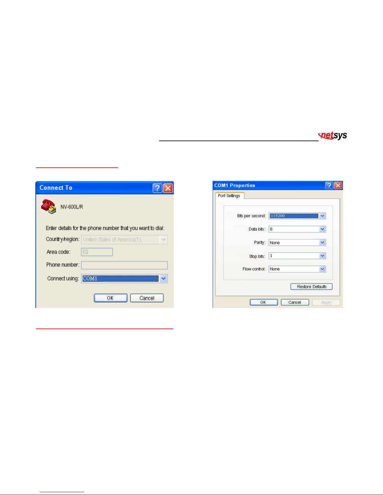
Open the Hyperterminal and set the baud rate to 115200, 8N1N to properly set the hyperterminal.
Figure 5 Hyperterminal Configuration
5.2 Reset the system to default configuration.
At the CLI command, write the command “rawaccess –e” to reset the system to default configuration. For it to take effect
write the command “reboot” to restart the system.
Page 26
NV600L/R VDSL2 CO&CPE Router USER’S MANUAL Ver.A15
25
6. Building a VDSL2 System
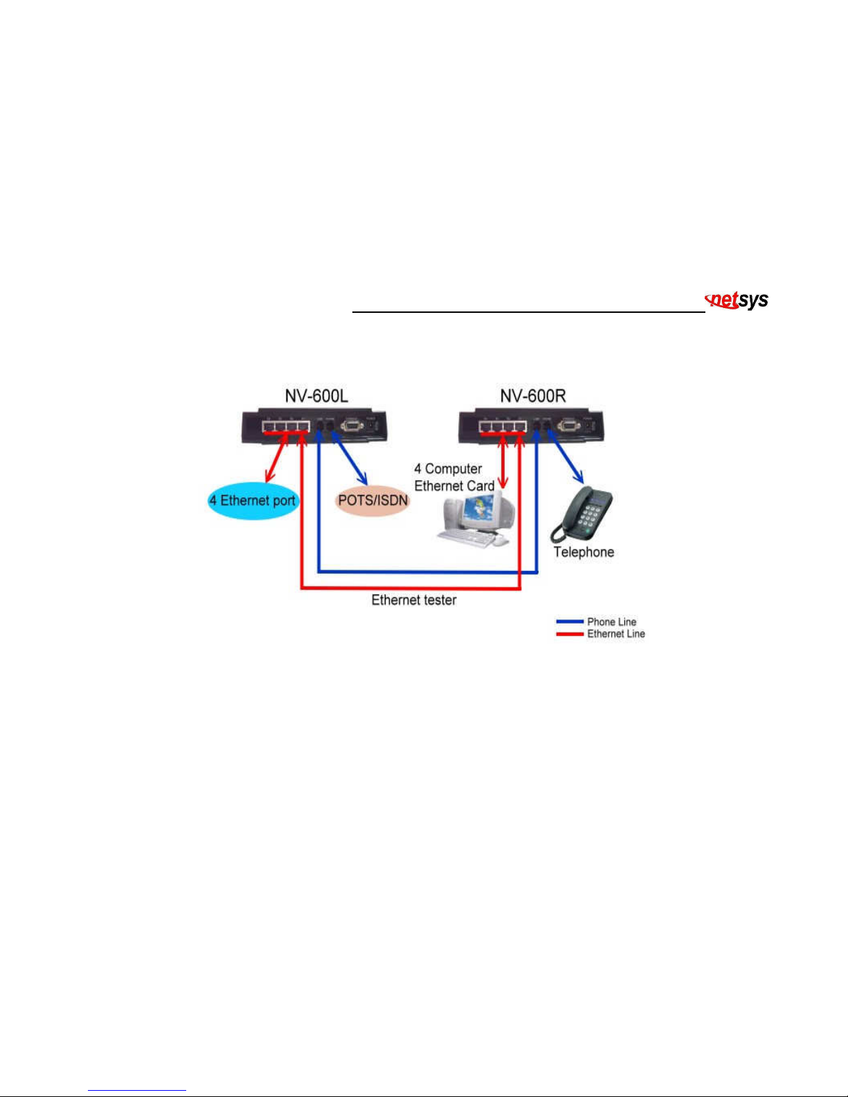
First a quick overview on a complete setup of NV-600L/R:
Figure 6 VDSL2 Application
Page 27

NV600L/R VDSL2 CO&CPE Router USER’S MANUAL Ver.A15
26
6.1 Connect the NV-600L and the NV-600R to the Line
The objective for VDSL2 is to pass high speed data over a twisted pair cable. In the setup, connects NV-600L to NV-600R
through phone wire or line simulator or any other hardware representation of a cable network, with or without noise
injection and crosstalk simulations.
6.2 Connect the NV-600L and the NV-600R to LAN Devices
In the setup, usually an Ethernet tester serves as representation of the LAN side as well as representation of the
WAN side.
6.3 Run Demos and Tests
The Ethernet tester may send data downstream as well as upstream. It also receives the data in order to check the
integrity of the data transmission. Different data rates can be tested under different line conditions.
Page 28

NV600L/R VDSL2 CO&CPE Router USER’S MANUAL Ver.A15
27
7. Operating the VDSL2 System
After the VDSL2 system has been set up, one may want to configure the settings that are related to VDSL2.
Configuration of operation modes, test modes (loop back) and the display of status information are supported by
GUI (Graphical User Interface).
7.1 Configuration Settings
Configure and start the NV-600L (CO) and the NV-600R (CPE).
• Configuration: As a minimum configuration, usually selecting the bandplan is required.
See Chapter 7.1.3, Profile Configuration.
• Next, both sides should be activated from the web interface.
See Chapter 7.1.6, Line Activation
• The connection status of the link can be monitored.
See Chapter 7.2.1, Line Status
Page 29
NV600L/R VDSL2 CO&CPE Router USER’S MANUAL Ver.A15
28
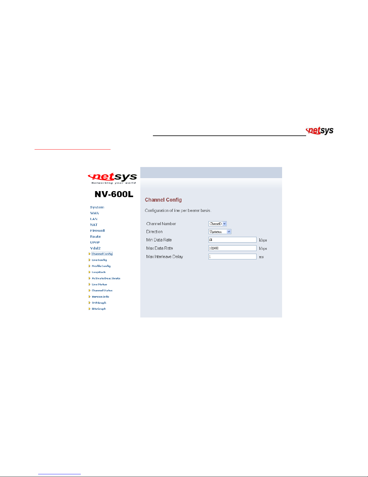
7.1.1 Channel Configuration
This function is for setting VDSL2 channel.
Figure 7.1.1 Channel Configuration Menu
Page 30
NV600L/R VDSL2 CO&CPE Router USER’S MANUAL Ver.A15
29
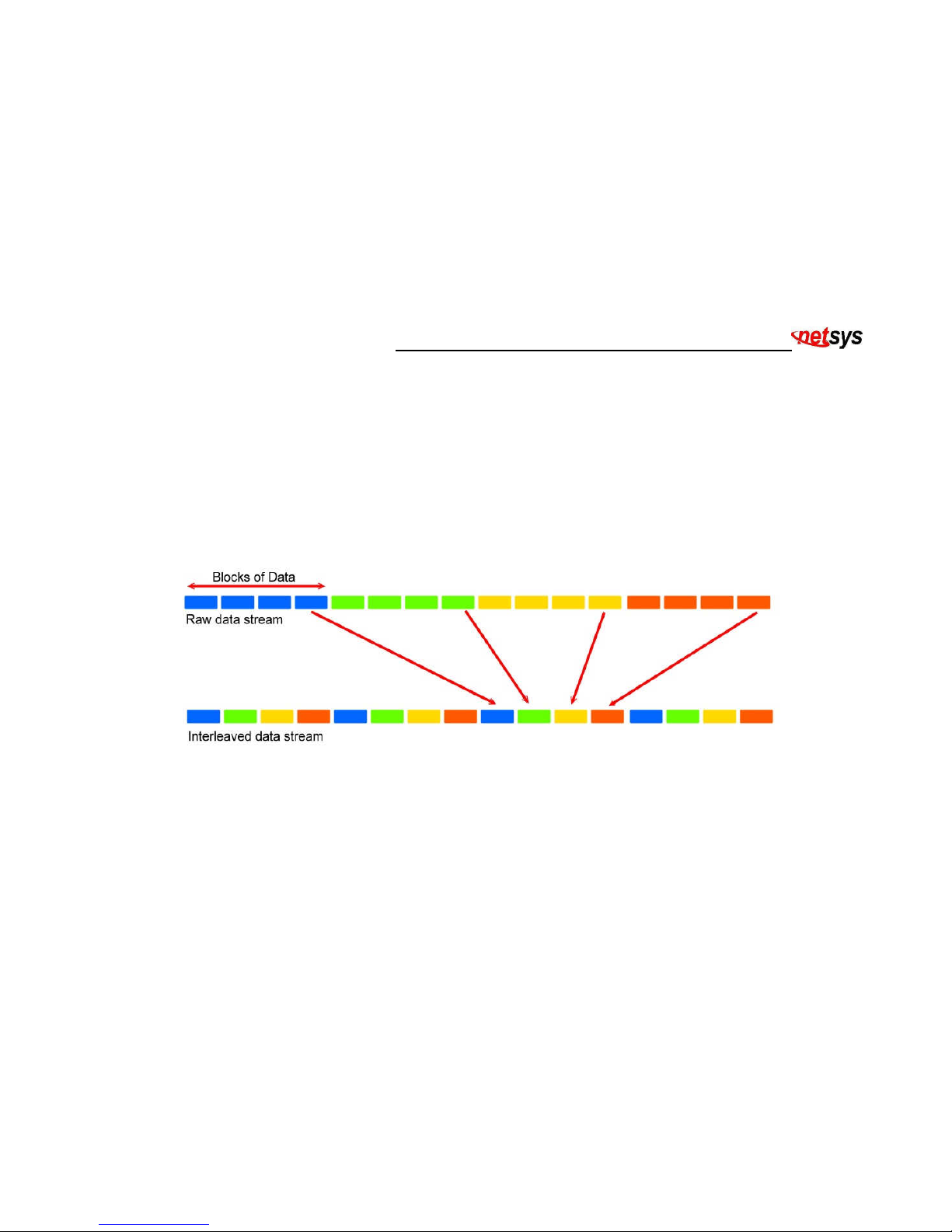
Interleave delay function is used in digital data transmission technology to protect the transmission against noise issue
and data error.
If during transit more than a certain amount of data has been lost then the data cannot be correctly decoded. Short bursts
of noise on the line can cause these data packets to become corrupt and the router has to re-request data which in turn
can slow down the overall rate at which data is transmitted.
Interleaving is a method of taking data packets, chopping them up into smaller bits and then rearranging them so that
once contiguous data is now spaced further apart into a non continuous stream. Data packets are re-assembled by your
router.
The diagram below is an example of how interleaved traffic is transmitted.
If your line is particularly susceptible to bursts of noise then interleaving should improve your VDSL2 experience simply
because if you lose a whole batch of data then this could cause your router to loose sync with the exchange.
Using Interleaving, the router is able to re-assemble the data or if necessary just re-request the part of the data that it is
unable to recover. By increasing the interleave depth of each ports that are susceptible to noise, this will improve error
performance and stability of marginal lines.
Page 31
NV600L/R VDSL2 CO&CPE Router USER’S MANUAL Ver.A15
30
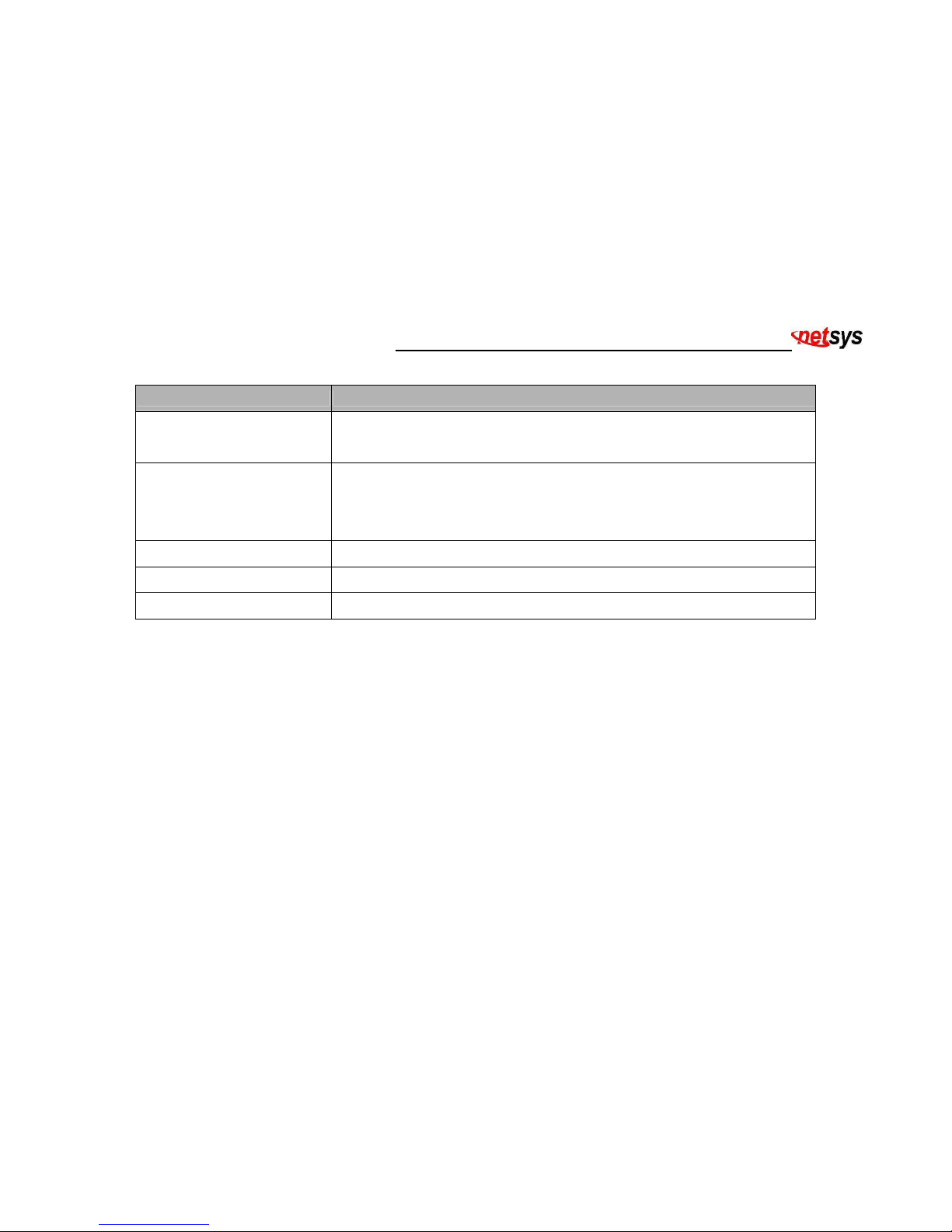
Channel Configuration Settings
Setting Description
Channel Number
To which bearer channel number shall the settings apply?
Channel 0
Direction
To which direction shall the settings apply?
Upstream
Downstream
Min Data Rate Minimum Payload Data Rate
Max Data Rate Maximum Payload Data Rate
Max Interleave Delay Maximum Interleave Delay (set from 0 to 255ms)
Note: The Reboot is needed for saving the new settings.
Page 32
NV600L/R VDSL2 CO&CPE Router USER’S MANUAL Ver.A15
31
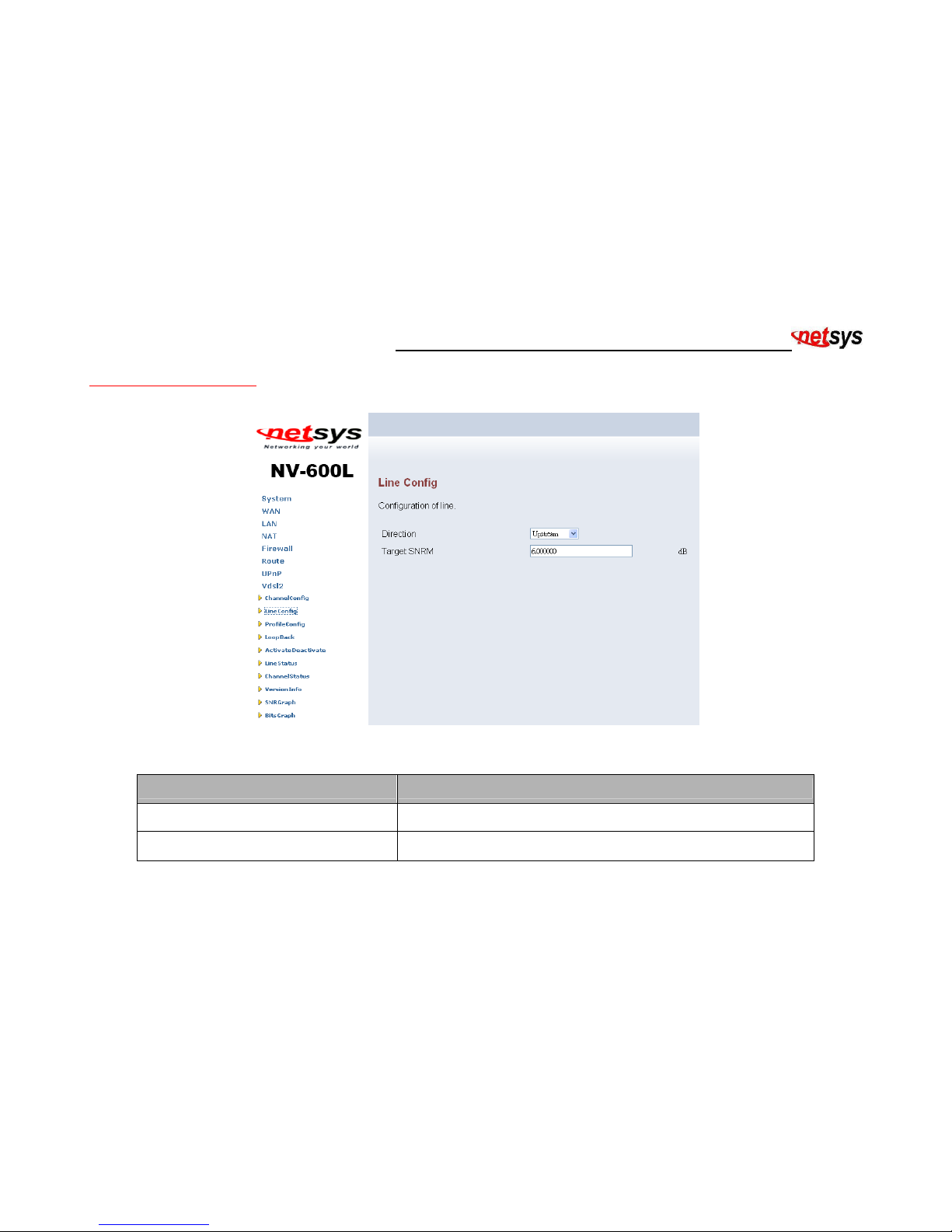
7.1.2 Line Configuration
Figure 7.1.2 Line Configuration Menu for SNR Margin Selection
Line Configuration
Setting Description
Direction Select the target direction.
Target SNRM Set the required SNR Margin *10 (60=6dB)
Page 33

NV600L/R VDSL2 CO&CPE Router USER’S MANUAL Ver.A15
32
7.1.3 Profile Configuration
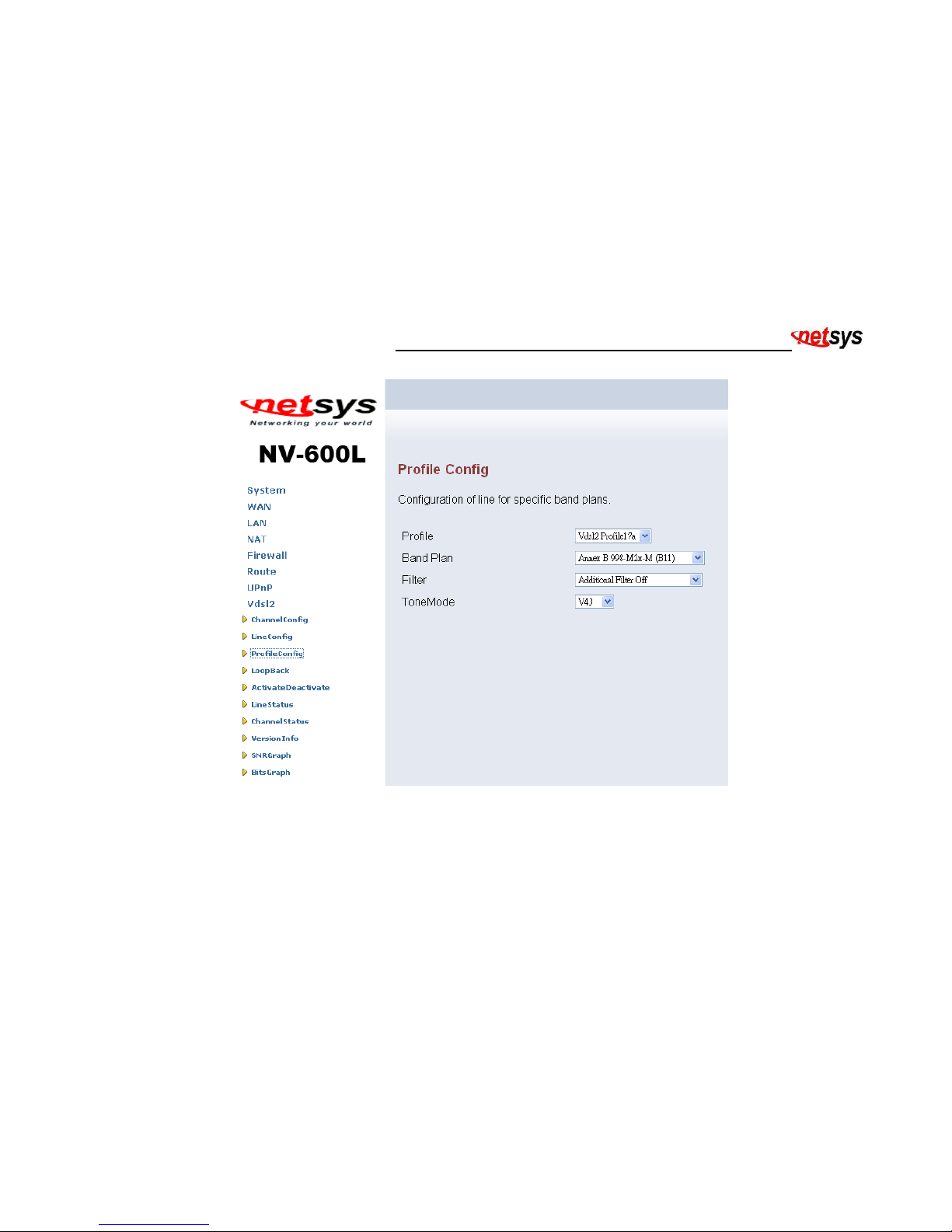
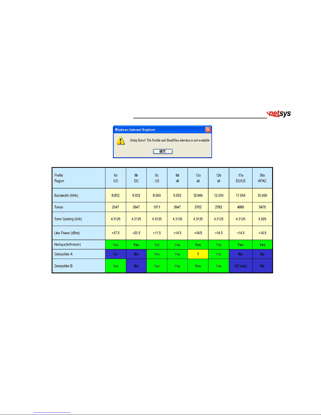
For this function, NV-600L/R provides world wide telecom standard band plan, such as meet European telecom standard
band plan 998(17a), USA telecom standard band plan 997(8a, 8b) and APAC Telecom standard band plan (30a) etc.
Annex A specifies bandplans for the North American region and enables NV-600 to be deployed with traditional POTS
telephony or in an all-digital mode. Annex B specifies bandplans for Europe and enables NV-600 deployment with
underlying POTS and ISDN services. Annex C allows NV-600 to coexist with TCM-ISDN services, found primarily in
APAC.
NV-600 has numerous configuration profiles and bandplans to meet regional service provider requirements. The
frequency bandwidth has increased to 30 MHz, with configuration options at 8.5 MHz, 12 MHz, 17.7 MHz and 30 MHz.
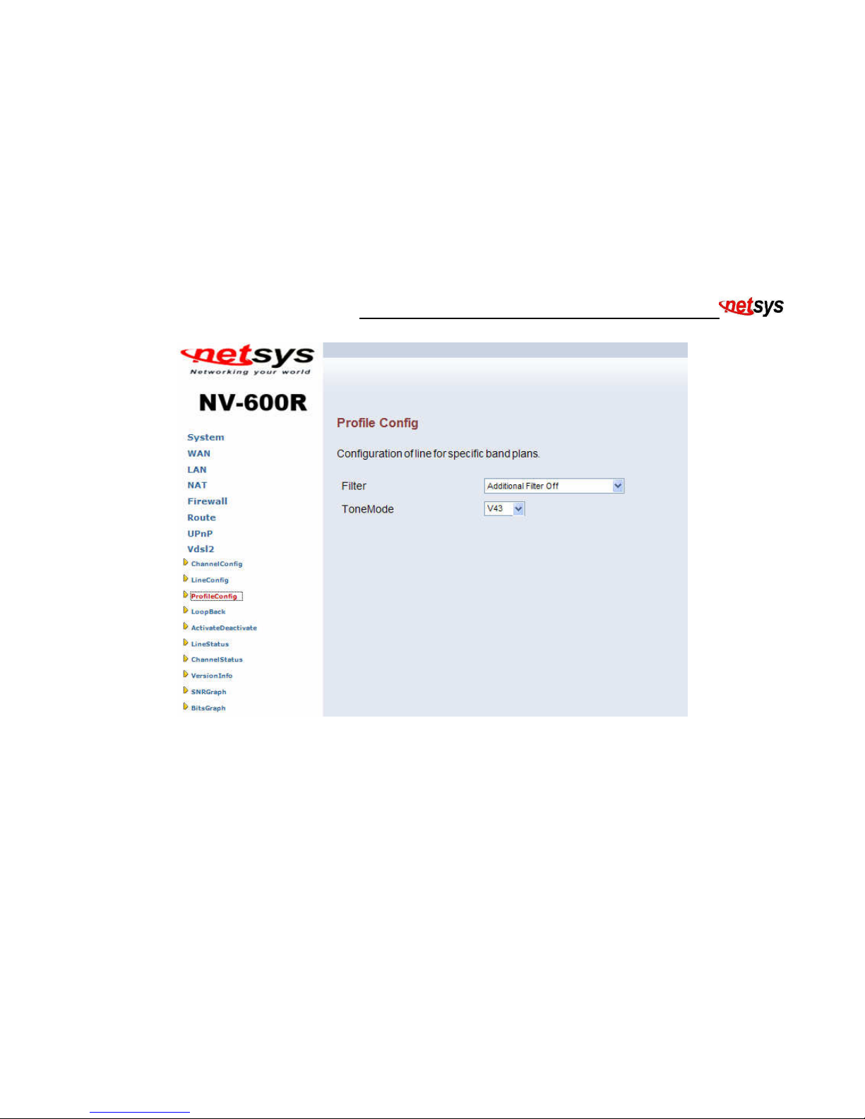
Band profile and band plan can only be configured at NV-600L as NV-600R will auto-follow up on the settings of NV-600L.
The only thing that NV-600R must be configured so that the routers will link is the tone mode. However, the default tone
mode for NV-600L/R is V43, so at default there’s no need to change the tone mode unless it is required by the telecom
companies to use different tone mode. Another important thing is that band profile and band plan setting must be
compatible to each other if not access error will show when applied. Please deactivate and activate once the setting has
been changed.
Page 34
NV600L/R VDSL2 CO&CPE Router USER’S MANUAL Ver.A15
33
Figure 7.1.3.1 NV-600L Profile Configuration
Page 35
NV600L/R VDSL2 CO&CPE Router USER’S MANUAL Ver.A15
34
Figure 7.1.3.2 NV-600R Profile Configuration
Page 36
NV600L/R VDSL2 CO&CPE Router USER’S MANUAL Ver.A15
35
Figure 7.1.3.3 Band Profile and Plan Setup Error
Figure 7.1.3.4 Band Profile Region
Page 37

NV600L/R VDSL2 CO&CPE Router USER’S MANUAL Ver.A15
36
The following shows the band profile and band plan compatibility:
Band Profile List
Band Plan List
0 VDSL2 Profile8a 0 Annex A M1_EU32
1 VDSL2 Profile8b 1 Annex A M9_EU64
2 VDSL2 Profile8c 8 Annex B 997-M2x-A (B05)
3 VDSL2 Profile8d 9 Annex B 997-M2x-M (B06)
4 VDSL2 Profile12a 10 Annex B 997-M1c-A-7 (B07)
5 VDSL2 Profile12b 11 Annex B 998-M1x-B (B08)
6 VDSL2 Profile17a 13 Annex B 998-M2x-A (B10)
7 VDSL2 Profile30a 14 Annex B 998-M2x-M (B11)
8 VDSL2 Profile17b 16 Annex B 998-M2x-B (B12)
18 Annex B 998-M2x-NUS0 (B13)
20 Annex C
21 Annex C_8K
22 Annex B 997-M2x-NUS0
23 Annex C 1M1
24 Annex C_8K 1M1
25 Annex B 998E17-M2x-A
26 Annex B 998E17-M2x-NUS0
Page 38

NV600L/R VDSL2 CO&CPE Router USER’S MANUAL Ver.A15
37
Band Profile \ Band Plan
0 1 8 9 10 11 13 14 16 18 20 21 22 23 24 25 26
0
O O O O O O O O O X X X X X X X X
1
O O O O O O O O O X X X X X X X X
2
X X O X O X X O X X X X X X X X X
3
O O O X O O O O O X X X X X X X X
4
O O O O O O O O O X X X X X X X X
5
O O X X O O O O O O X X X X X X X
6
O X X X O O O O O X O X X O X X O
7
O X X X X X X X X X X O O X O X X
8
X X X X X X X O O X X X X X X O X
Note: O = Compatible; X = Not Compatible
Page 39

NV600L/R VDSL2 CO&CPE Router USER’S MANUAL Ver.A15
38
The following phone cable distance and data rates are possible according to the band profile and band plan setup:
Default plan profile and band plan = 30a and C8K
At distance 0-350m, data rates are at 100Mbps for both downstream and upstream
350-450m, data rates are at 70-85/40Mbps for downstream/upstream
450-600m at 40-60/10Mbps for downstream/upstream
600-900m at 20-40/1-5Mbps for downstream/upstream
Note: Using Band profile 30a and band plan C8K for distances beyond 900m is not recommended
Alternative band profile and band plan = 8d and M1_EU32
At distance 0-800m, data rates are at 60-80/15Mbps for both downstream/upstream.
800-1200m, data rates are at 30-50/5-10Mbps for downstream/upstream
1200-1500m, data rates are at 30/2-5Mbps for downstream/upstream
Note: Using Band profile 8d and band plan M1_EU32 for distances beyond 1500m is not recommended
Additional: Downstream: Traffic from Transmitter to Receiver
Upstream: Traffic from Receiver to Transmitter
Page 40
NV600L/R VDSL2 CO&CPE Router USER’S MANUAL Ver.A15
39
7.1.4 Loop Back
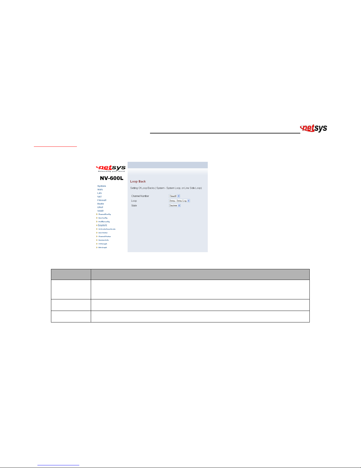
The loop back testing function for checking phone wire link problem: 1. System Loop. 2. Line Side Loop
Figure 7.1.4 Loop Back Activation/Deactivation Menu
Loop Back
Setting Description
Channel No.
To which bearer channel number shall the settings apply?
Channel 0
Loop System loop or line side loop
State Activate or deactivate loop back within the transmission convergence layer
Page 41
NV600L/R VDSL2 CO&CPE Router USER’S MANUAL Ver.A15
40
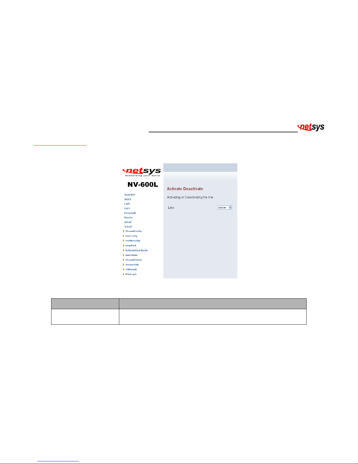
7.1.5 Line Activation
This function is for enable/disable VDSL2 port.
Figure 7.1.5 Activation and Deactivation of the Line
Line Activation/Deactivation
Setting Description
Line
Activate or deactivate the line. (Select the activity and the press the APPLY
button.)
Page 42
NV600L/R VDSL2 CO&CPE Router USER’S MANUAL Ver.A15
41
7.2 Status Displays
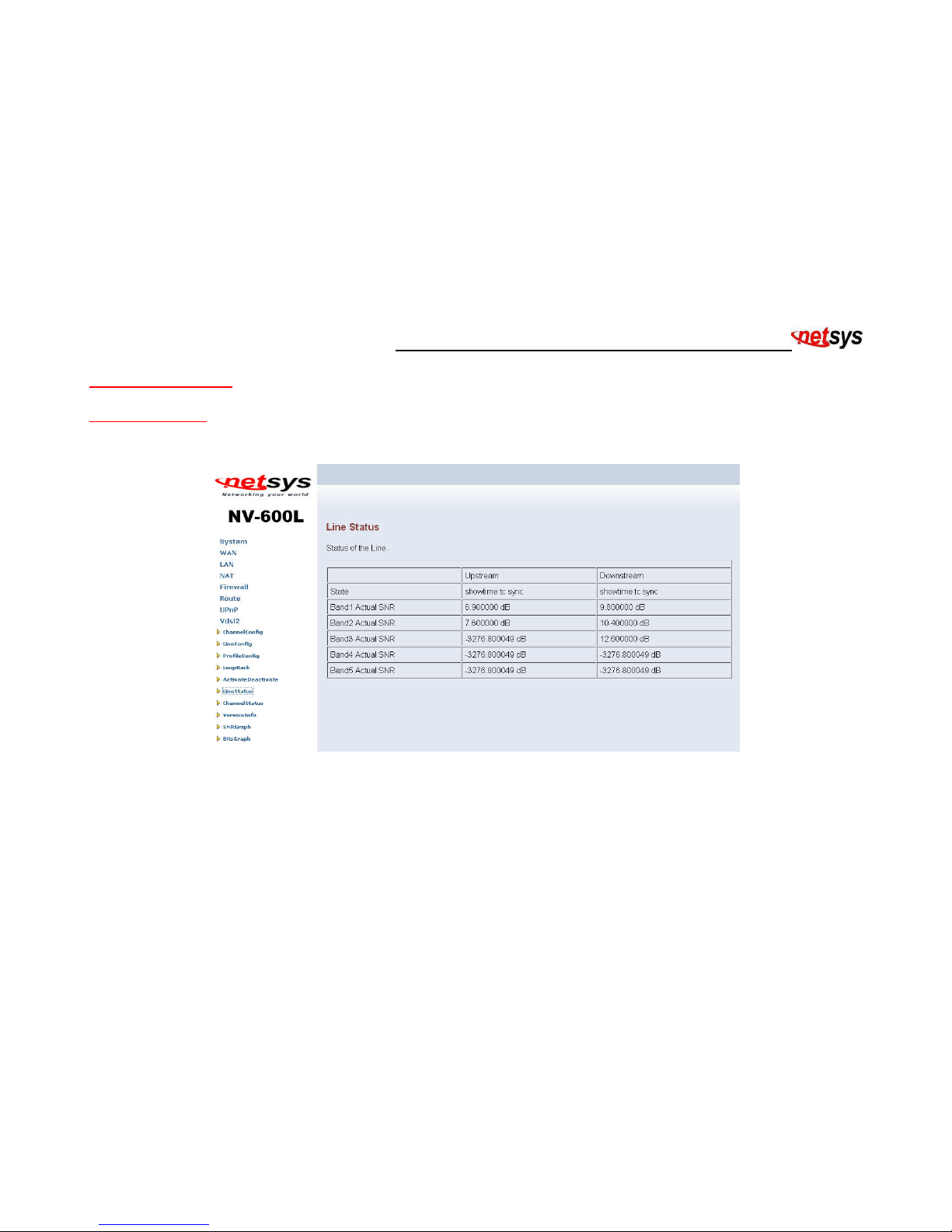
7.2.1 Line Status
This function provides SNR value for checking phone wiring quality.
Figure 7.2.1 Line Status Display: Actual SNR
The following status messages may occur: not_initialized, exception, idle request, idle, silent request, silent, handshake,
full init, discovery, training, analysis, exchange, showtime no sync, showtime tc sync, fast retrain, lowpower l2,
loopdiagnostic, loopdiagnostic complete, resync, test, lowpower l3, unknown.
Page 43
NV600L/R VDSL2 CO&CPE Router USER’S MANUAL Ver.A15
42
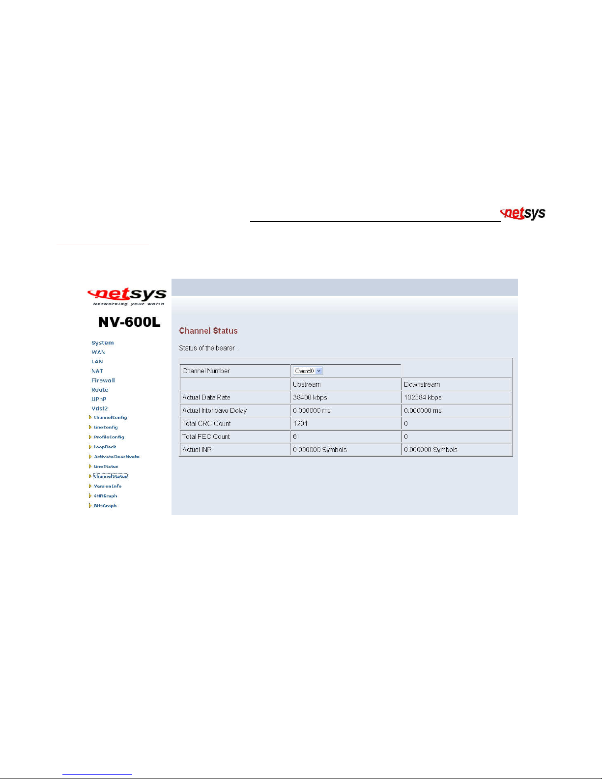
7.2.2 Channel Status
This function shows VDSL2 port status.
Figure 7.2.2 Channel Status Display: Data Rate, Delay, Error Counters and Impulse Noise Protection
Page 44
NV600L/R VDSL2 CO&CPE Router USER’S MANUAL Ver.A15
43
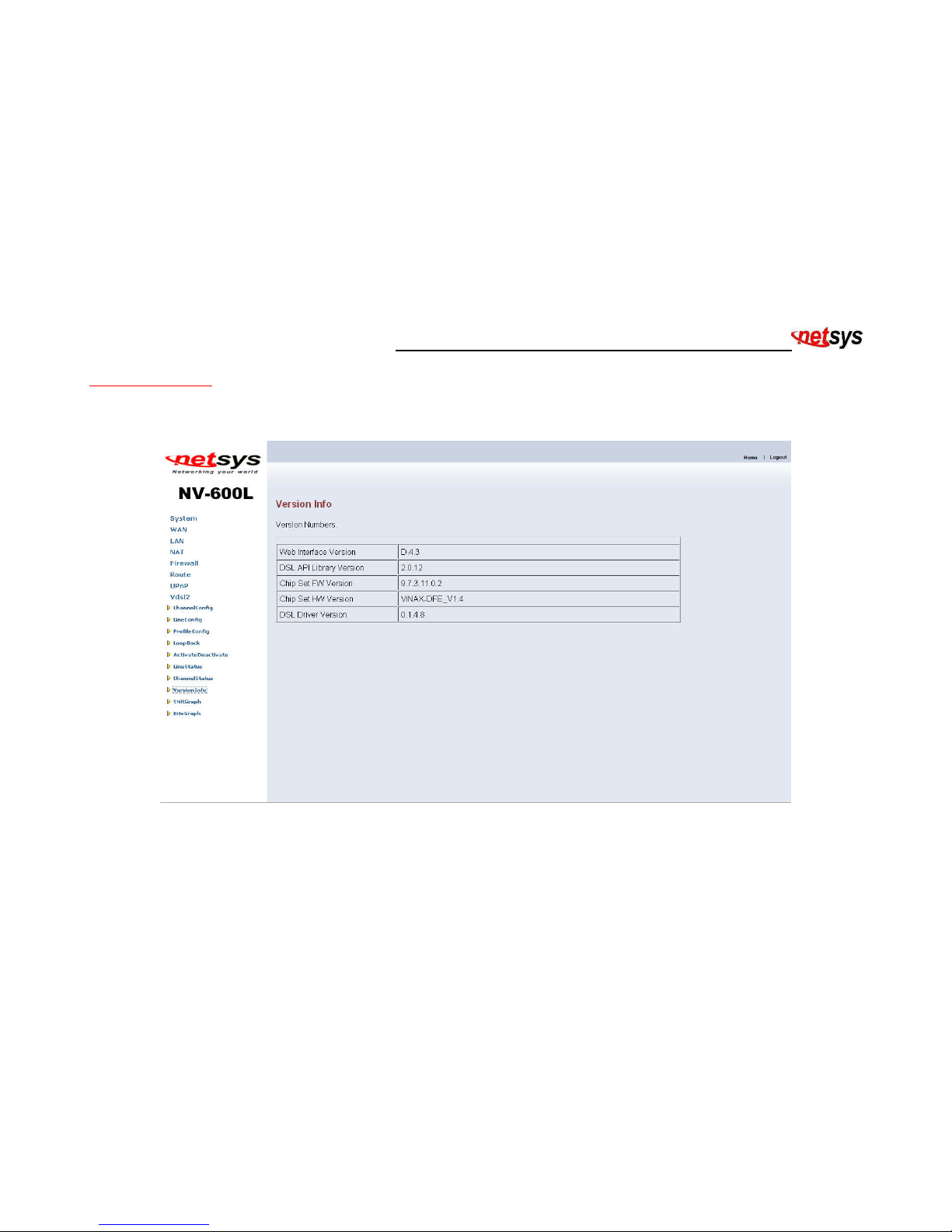
7.2.3 Version Info
This function shows hardware and firmware version.
Figure 7.2.3 Display of Version Data
Page 45
NV600L/R VDSL2 CO&CPE Router USER’S MANUAL Ver.A15
44
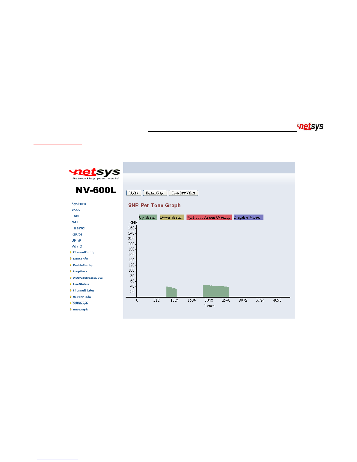
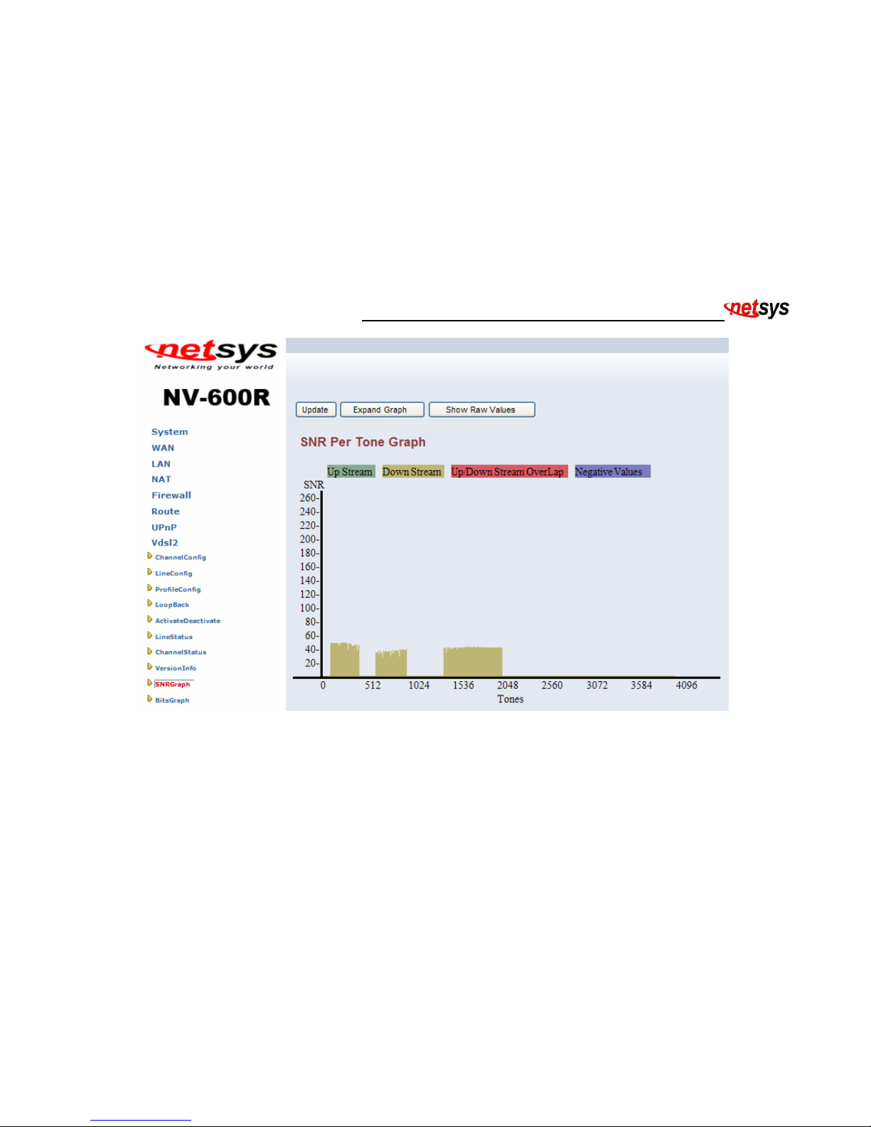
7.2.4 SNR Graphs
When NV-600L link with NV-600R, this graph will show the SNR value for each band.
Page 46
NV600L/R VDSL2 CO&CPE Router USER’S MANUAL Ver.A15
45
Figure 7.2.4 Display of SNR per Carrier
Page 47
NV600L/R VDSL2 CO&CPE Router USER’S MANUAL Ver.A15
46
7.2.5 BitsGraphs
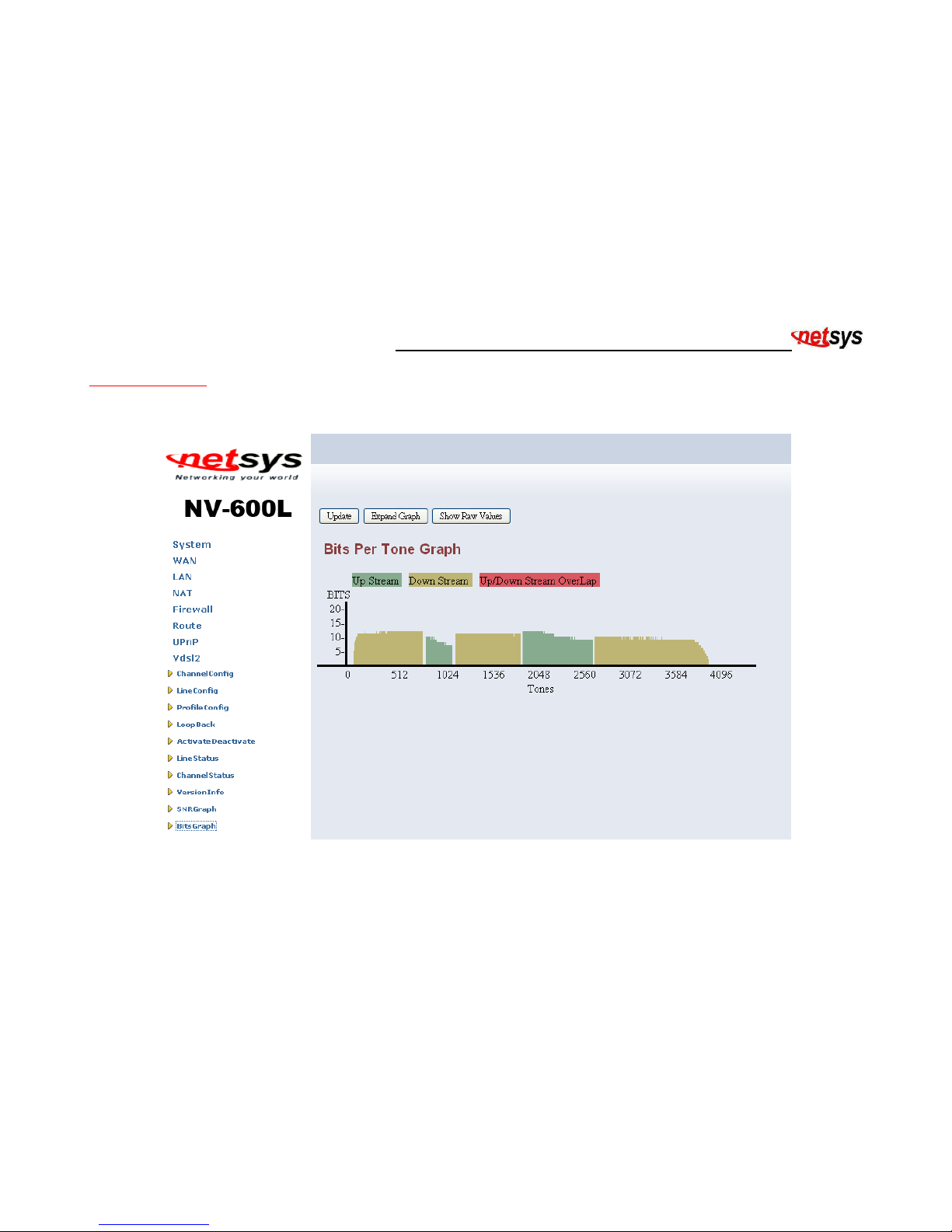
When NV-600L link with NV-600R, this graph will show the bits value for each tone.
Figure 7.2.5 Display Bits Per Tone Graph
Page 48

NV600L/R VDSL2 CO&CPE Router USER’S MANUAL Ver.A15
47
8. Configuration Interface of the Router
This section explains how to configure the router section of the NV-600L/R using its web-based configuration.
The part of the circuitry as well as the router configuration menu has been ported from that of the reference kit to
the NV-600L/R reference board. As for the menu, there are only a few differences:
The “adm1” port now is the port to the VDSL2 side. The port on the LAN is “adm0”. It supports four Ethernet
connections.
The IP addresses are used in this chapter are different from the examples in the previous chapters.
The password used in this chapter is different from the examples in the previous chapters.
Page 49
NV600L/R VDSL2 CO&CPE Router USER’S MANUAL Ver.A15
48
8.1 Logging in to the NV-600L/R
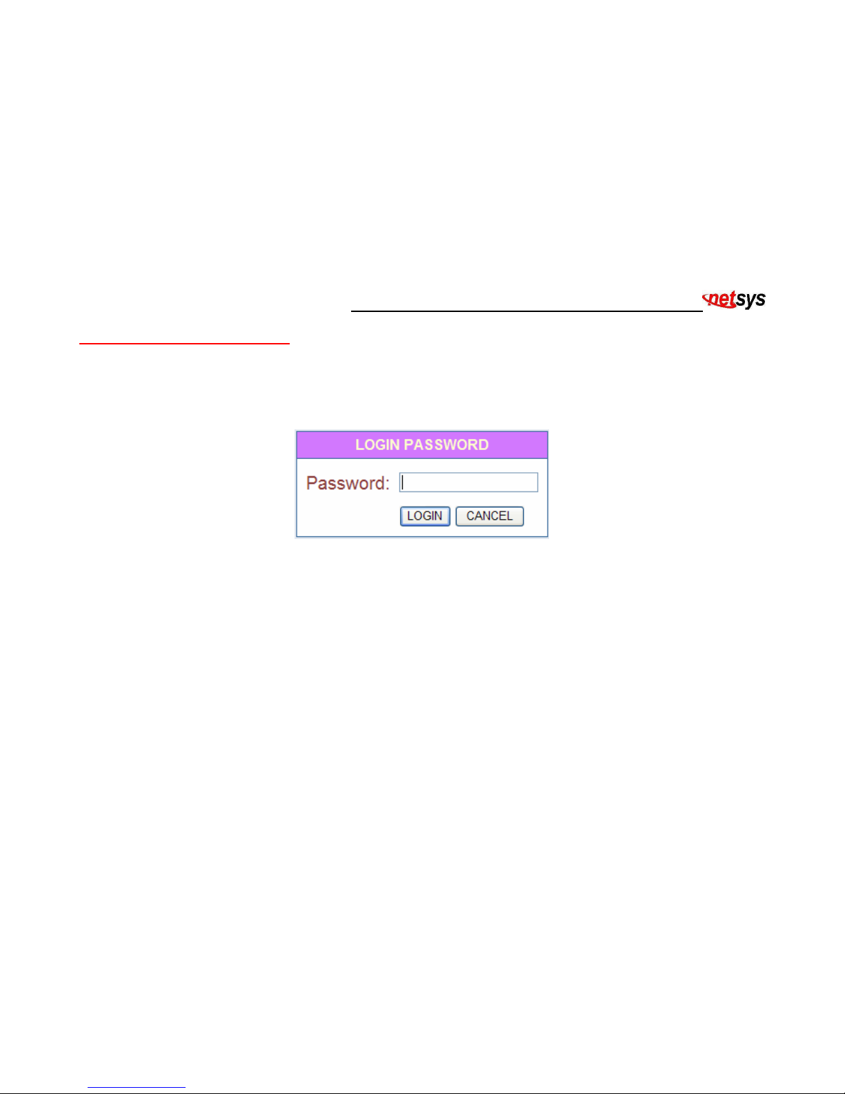
To log on to the NV-600L/R Web Application, you must have a valid password. The Administrator creates the log on user
with its password. When one log on to the NV-600L/R Web Application, the LOGIN PASSWORD window is displayed as
shown in Figure 8.1.
Figure 8.1 NV-600L/R Web Application
In the LOGIN PASSWORD window:
1. Enter the password in the Password text box. For an Admin user, the default password is “admin”.
2. Click LOGIN to begin the configuration or click CANCEL in the LOGIN PASSWORD window to cancel this log on
operation.
Page 50
NV600L/R VDSL2 CO&CPE Router USER’S MANUAL Ver.A15
49
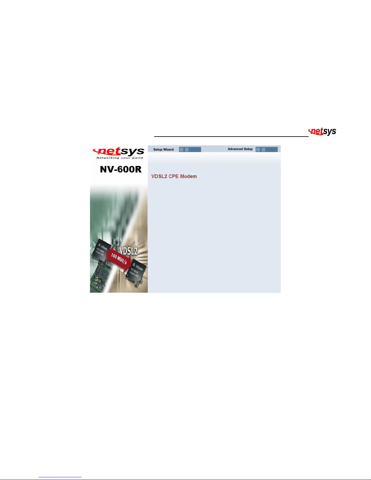
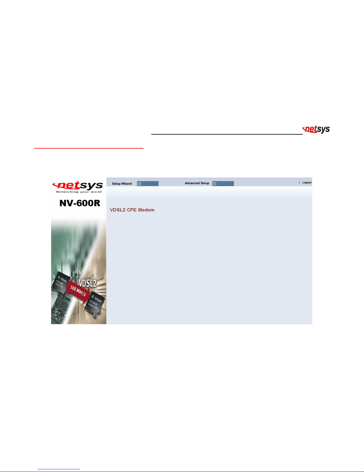
8.2 Setup Wizard and Advanced Setup
There is an easy Setup Wizard for end users at the NVF-200R side and an Advanced Setup for more detail configurations
for both NV-600L/R. This manual gives importance to the Advanced Setup.
Figure 8.2 Select the Advanced Setup in the Entry Screen
Page 51
NV600L/R VDSL2 CO&CPE Router USER’S MANUAL Ver.A15
50
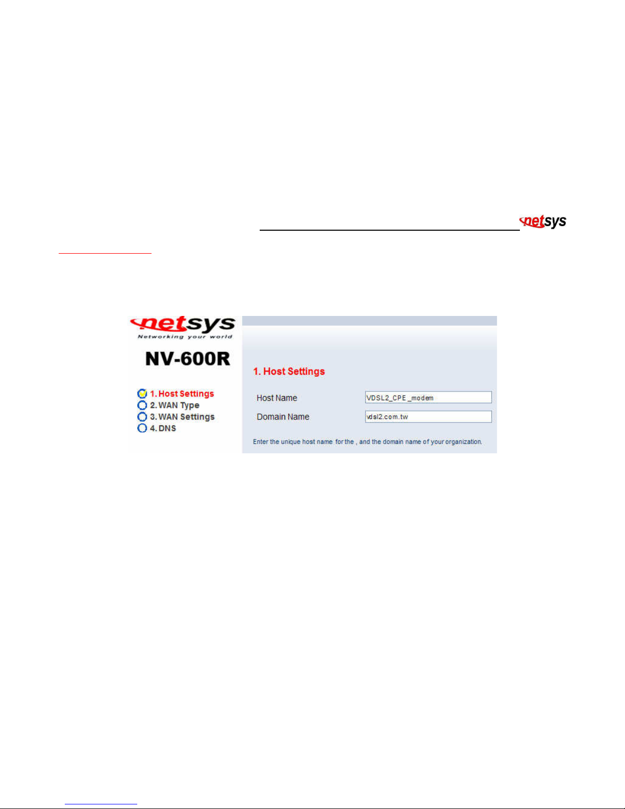
8.2.1 Setup Wizard
The Setup Wizard is designed for ease-of-use in order to quickly configure the most common settings. The Admin can
view the Setup Wizard link in the homepage. The wizard first step is to allow the admin to configure the system host
settings displayed as shown in Figure 8.2.1.
Figure 8.2.1 Setup Wizard’s First Step
There are four steps to complete the wizard. Follow the instructions given in each step and enter the desired settings.
Page 52
NV600L/R VDSL2 CO&CPE Router USER’S MANUAL Ver.A15
51
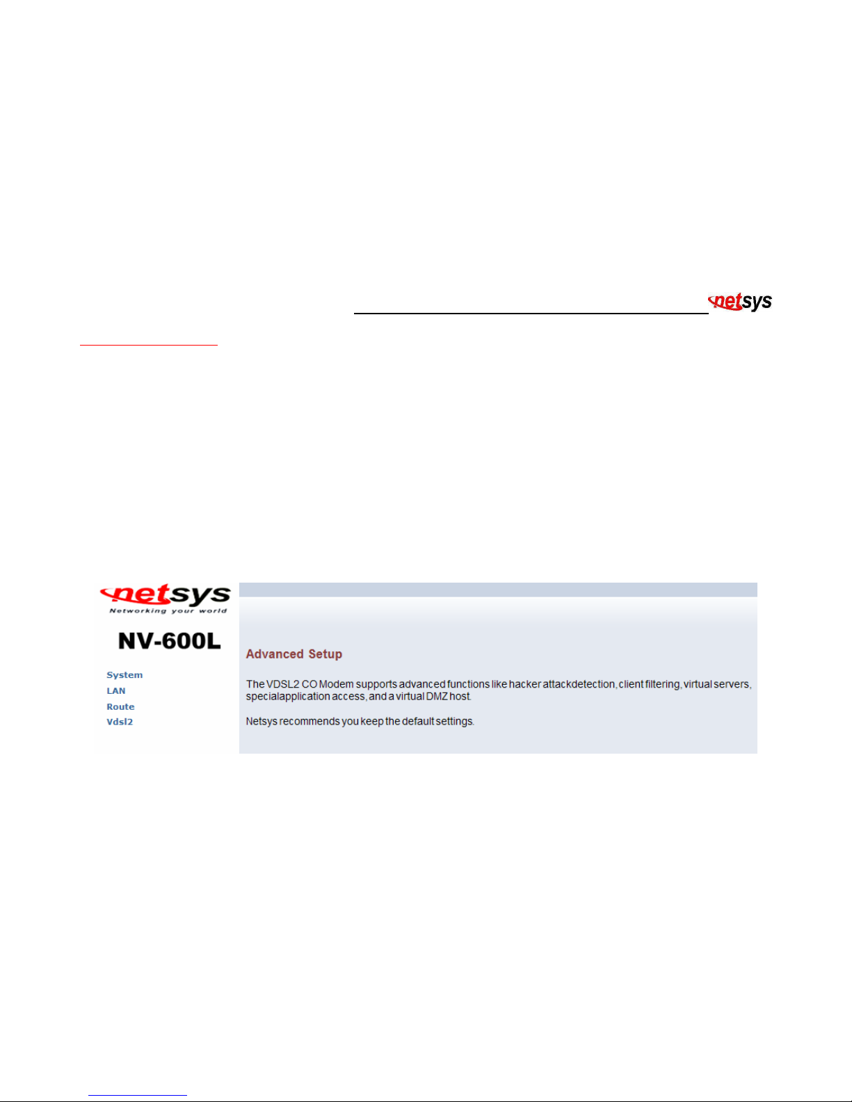
8.2.2 Advanced Setup
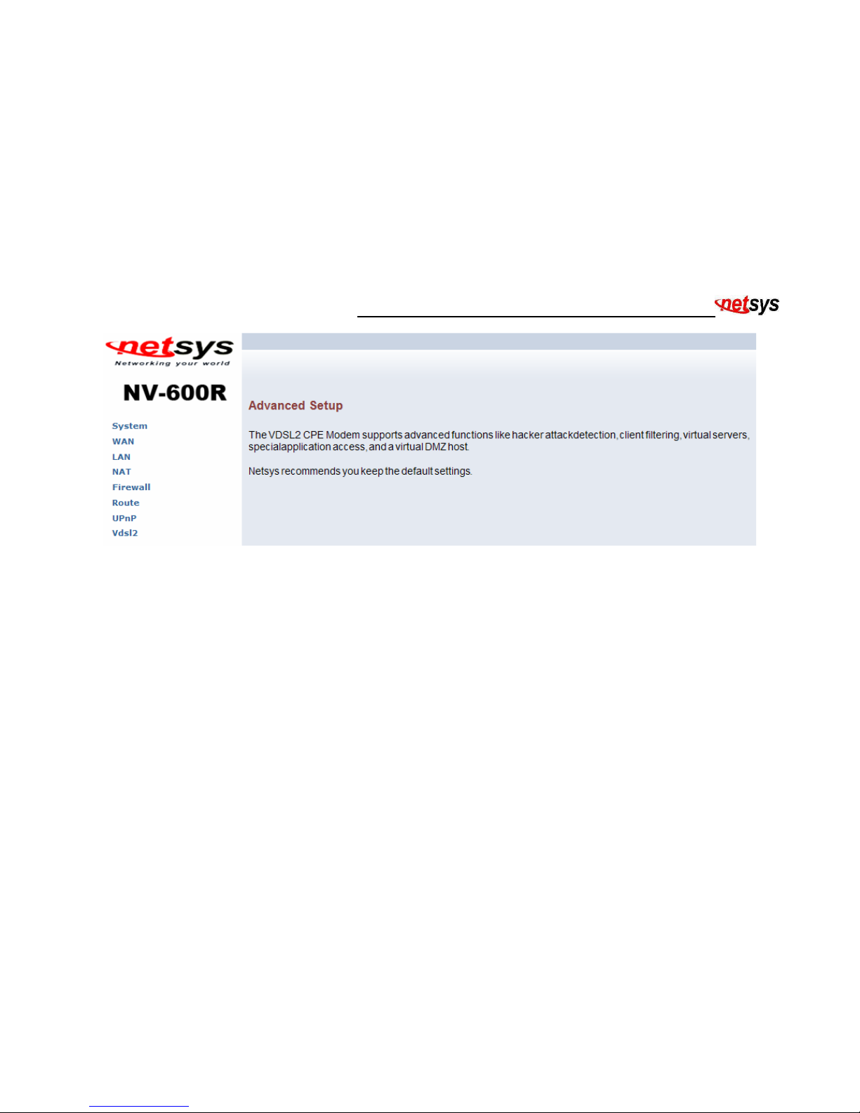
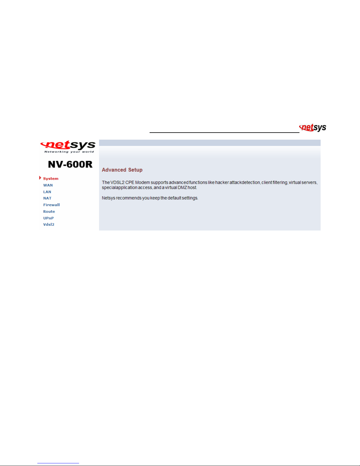
Click on the Advanced Setup link in the homepage in case you want to configure a wider range of settings. Router setup
are only located at NV-600R. So the WAN, NAT, Firewall and UPnP are only seen at NV-600 advanced setup menu. The
following configuration options are displayed in the left navigation bar, as shown in Figure 8.2.2.
• System
• WAN (NV-600R only)
• LAN
• NAT (NV-600R only)
• Firewall (NV-600R only)
• Route
• UPnP (NV-600R only)
• VDSL2
Page 53
NV600L/R VDSL2 CO&CPE Router USER’S MANUAL Ver.A15
52
Figure 8.2.2 Advanced Setup
Page 54
NV600L/R VDSL2 CO&CPE Router USER’S MANUAL Ver.A15
53
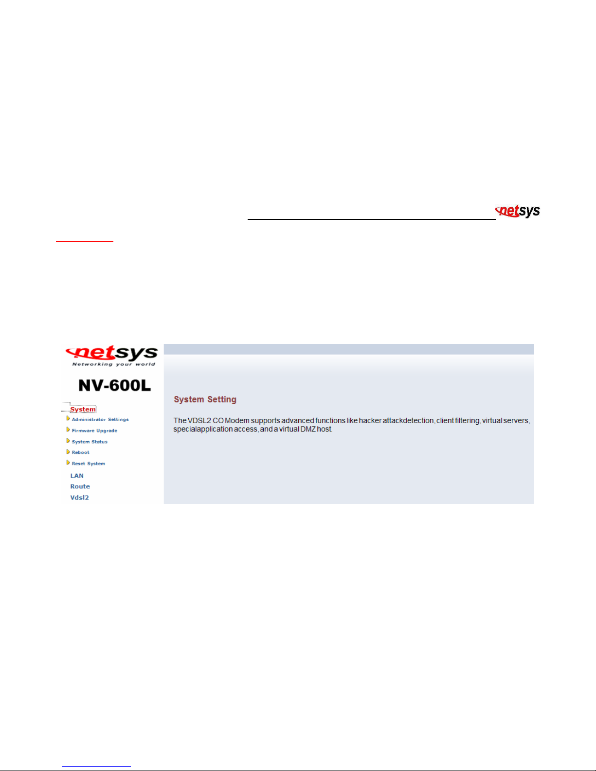
8.2.3 System
The System link can be viewed in the left navigation bar. The following are the options available under System, as shown
in Figure 8.2.3.
• Administrator Settings
• Firmware Upgrade
• Device Mode (NV-600R only)
• System Status
• Reboot
• Reset System
Figure 8.2.3 System in the Left Navigator Bar
Page 55
NV600L/R VDSL2 CO&CPE Router USER’S MANUAL Ver.A15
54
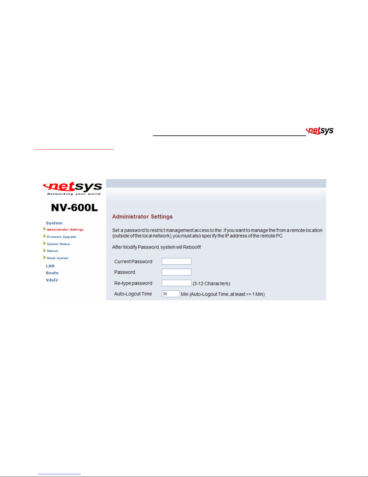
8.2.3.1 Administrator Settings
To add a user or change user’s password, click on the Administrator Settings link in the left navigation bar. A screen is
displayed as shown in Figure 8.2.3.1.
Figure 8.2.3.1 Administrator Settings Configuration
While adding a user, each user must assign a separate port. Hence the number of users that can be added to the system
depends on the number of ports available on the NV-600L/R.
Page 56
NV600L/R VDSL2 CO&CPE Router USER’S MANUAL Ver.A15
55
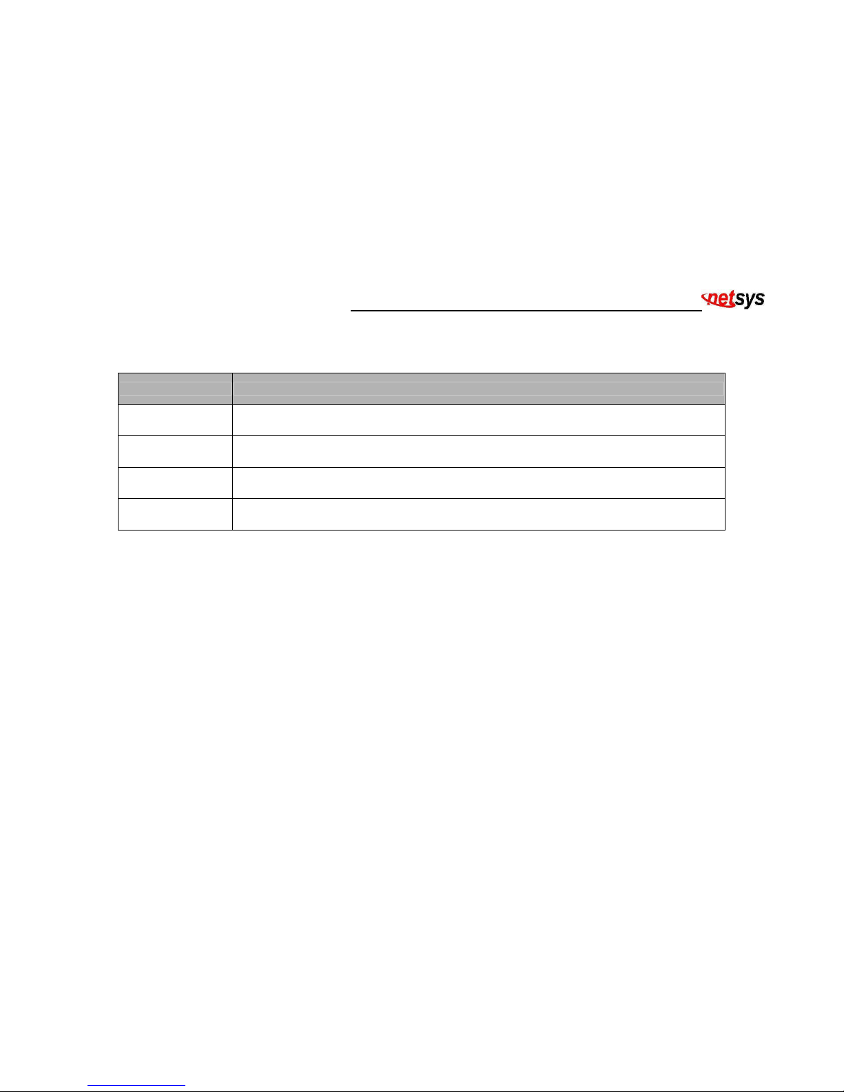
The screen contains the following details:
Fields in User Setting
Field Description
Current Password
This is the password associated with the administrator. This is enabled only for the
user
Administrator login.
Password This is the password of the login administrator.
Re-type Password This is the password verification.
Auto-Logout Time The auto-logout time, at least one minute.
• Click APPLY to save the information that has been entered.
• Click CANCEL to exit from this page without saving the changes.
Page 57
NV600L/R VDSL2 CO&CPE Router USER’S MANUAL Ver.A15
56
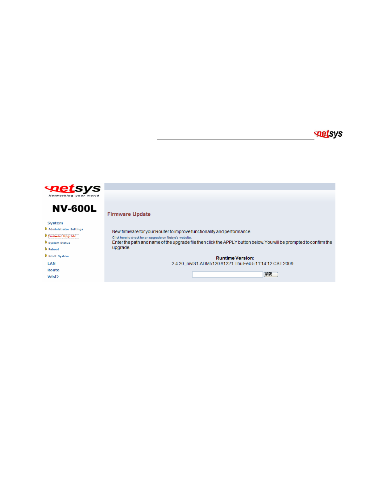
8.2.3.2 Firmware Upgrade
To update the system firmware, click on the Firmware Upgrade link in the left navigation bar. A screen is displayed as
shown in 8.2.3.2
Figure 8.2.3.2 Firmware Update
The screen contains the following detail:
•
Click APPLY to start the firmware update.
• Click Browse to select a specified file name to change the File Name.
Page 58
NV600L/R VDSL2 CO&CPE Router USER’S MANUAL Ver.A15
57
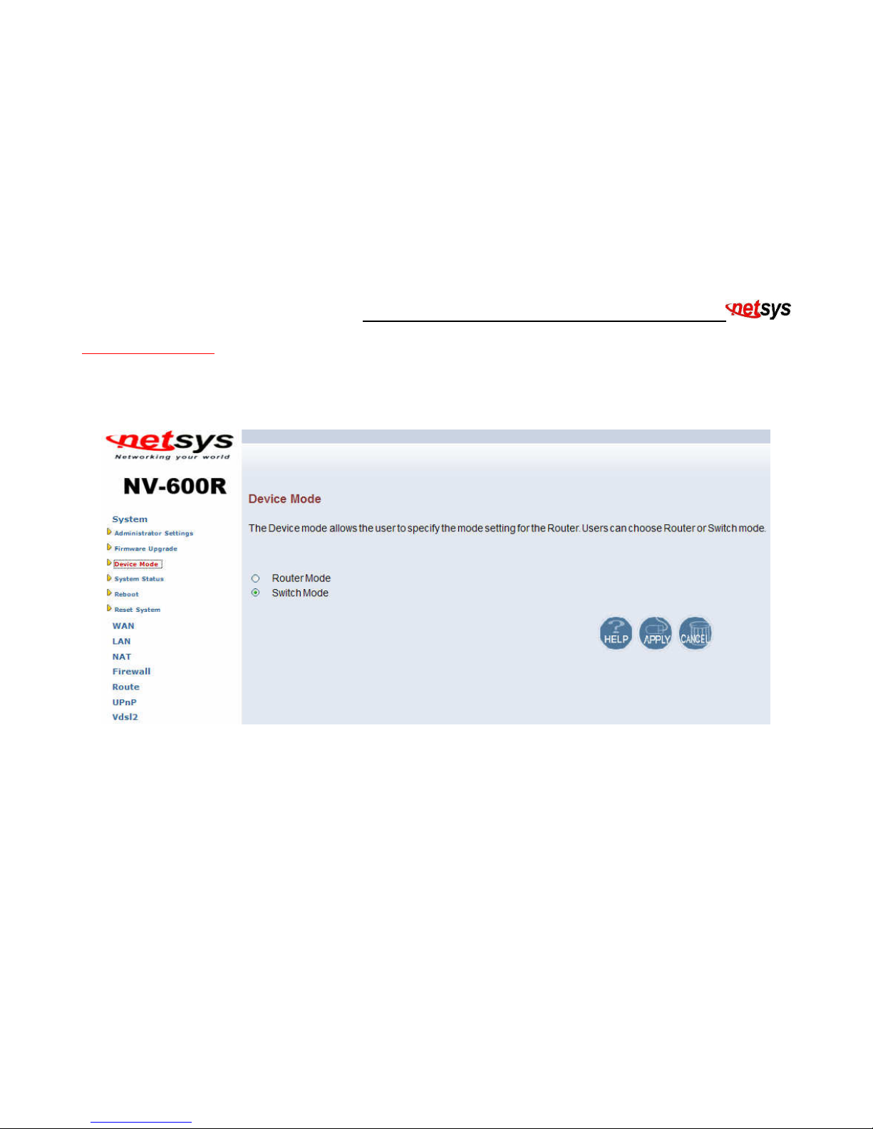
8.2.3.3 Device Mode
The ADM5120 network processor used in the reference system is able to act as either a switch or a router. Clicking on
Device Mode on the left navigation bar allows the user to change the mode of operation, as shown in the following figure.
Figure 8.2.3.3 Device Mode
The default setting is in Switch mode, it is not necessary to change the setting in most of the case. In situations, which
devices (e.g. PC, Server, VoIP) connected to CPE requires Router function. Hence, set the CPE on Router mode.
Page 59
NV600L/R VDSL2 CO&CPE Router USER’S MANUAL Ver.A15
58
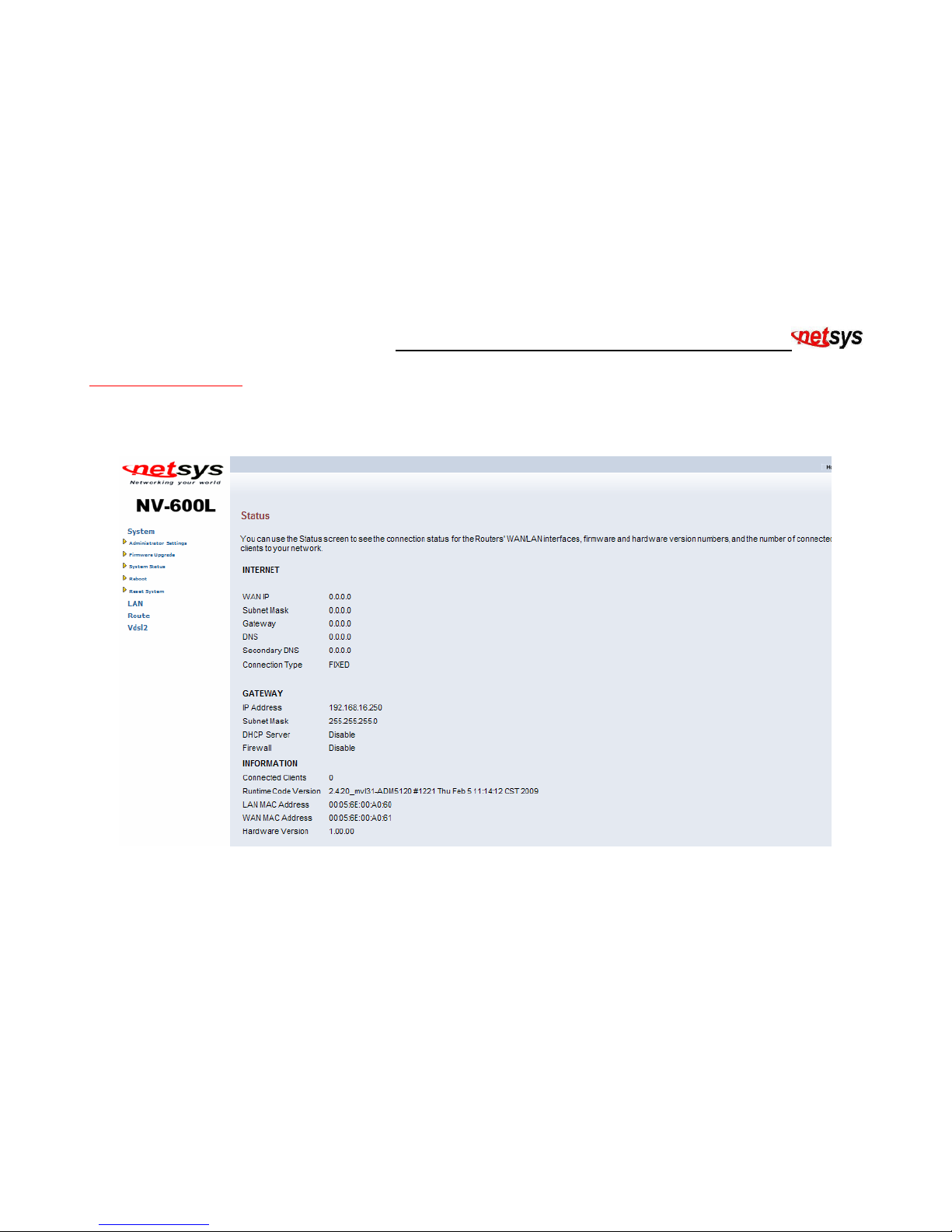
8.2.3.4 System Status
To view system status, click on the System Status link in the left navigation bar. A screen is displayed as shown in
Figure 8.2.3.4
Figure 8.2.3.4 Status Window
Page 60
NV600L/R VDSL2 CO&CPE Router USER’S MANUAL Ver.A15
59
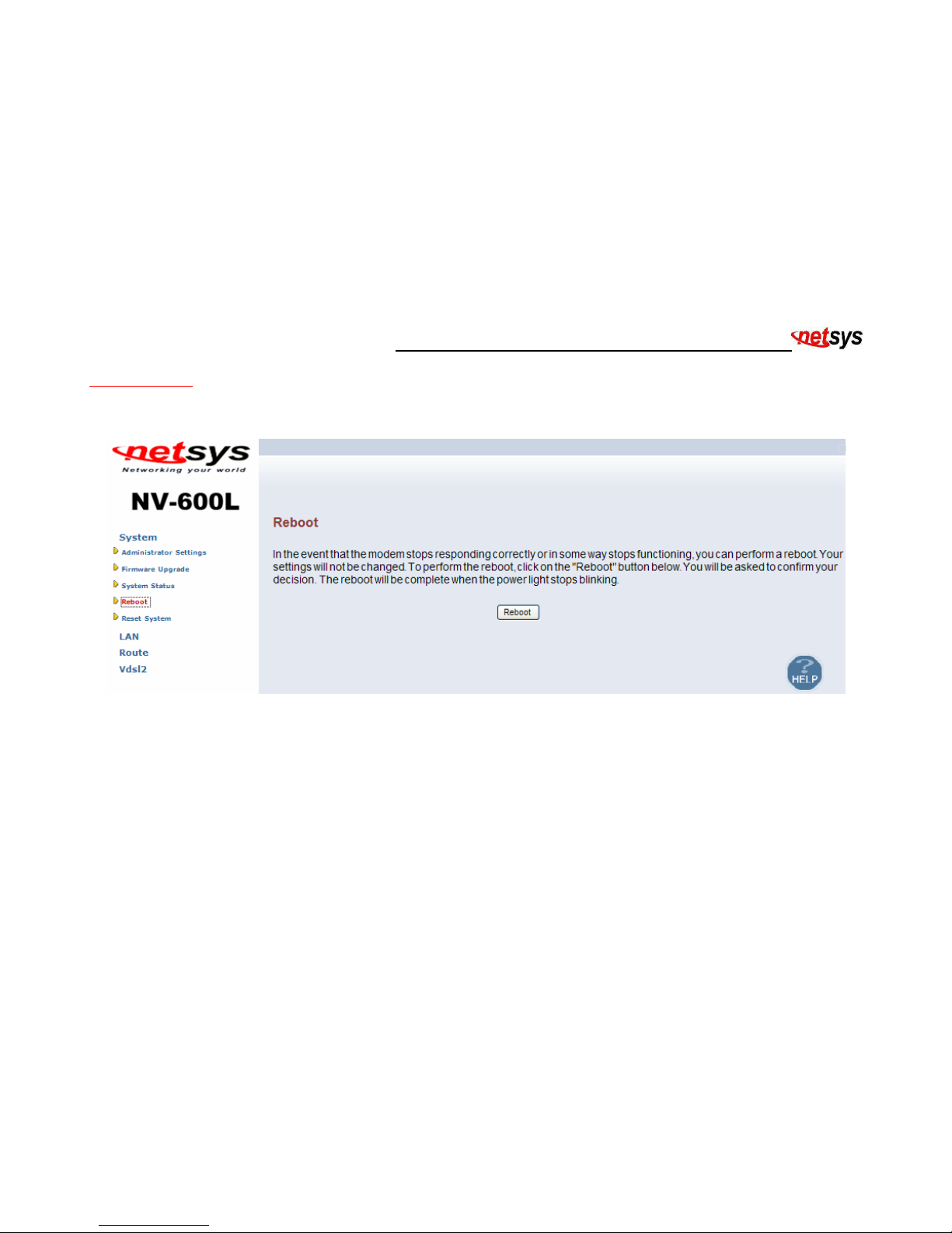
8.2.3.5 Reboot
To reboot the unit, click on the Reboot link in the left navigation bar. A screen is displayed as shown in Figure 8.2.3.5.
Figure 8.2.3.5 Reboot NV-600L/R Router
• Click Reboot to restart the unit.
Page 61
NV600L/R VDSL2 CO&CPE Router USER’S MANUAL Ver.A15
60
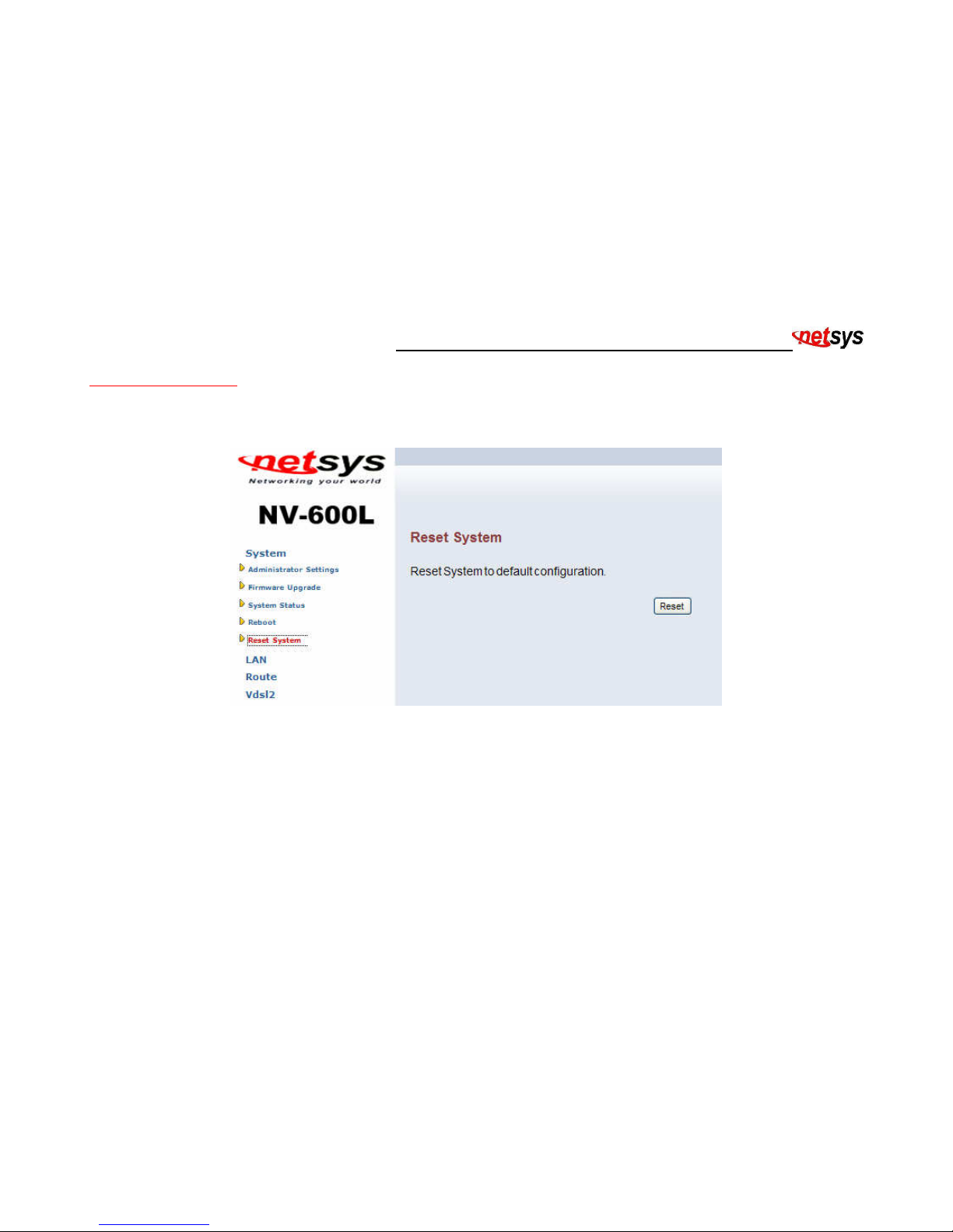
8.2.3.6 Reset system
To reset the system, click on the Reset link in the left navigation bar. A screen is displayed as shown in Figure 8.2.3.6.
Figure 8.2.3.6 Reset NV-600L/R Router
• Click Reset to restart the system to default configuration.
Page 62
NV600L/R VDSL2 CO&CPE Router USER’S MANUAL Ver.A15
61
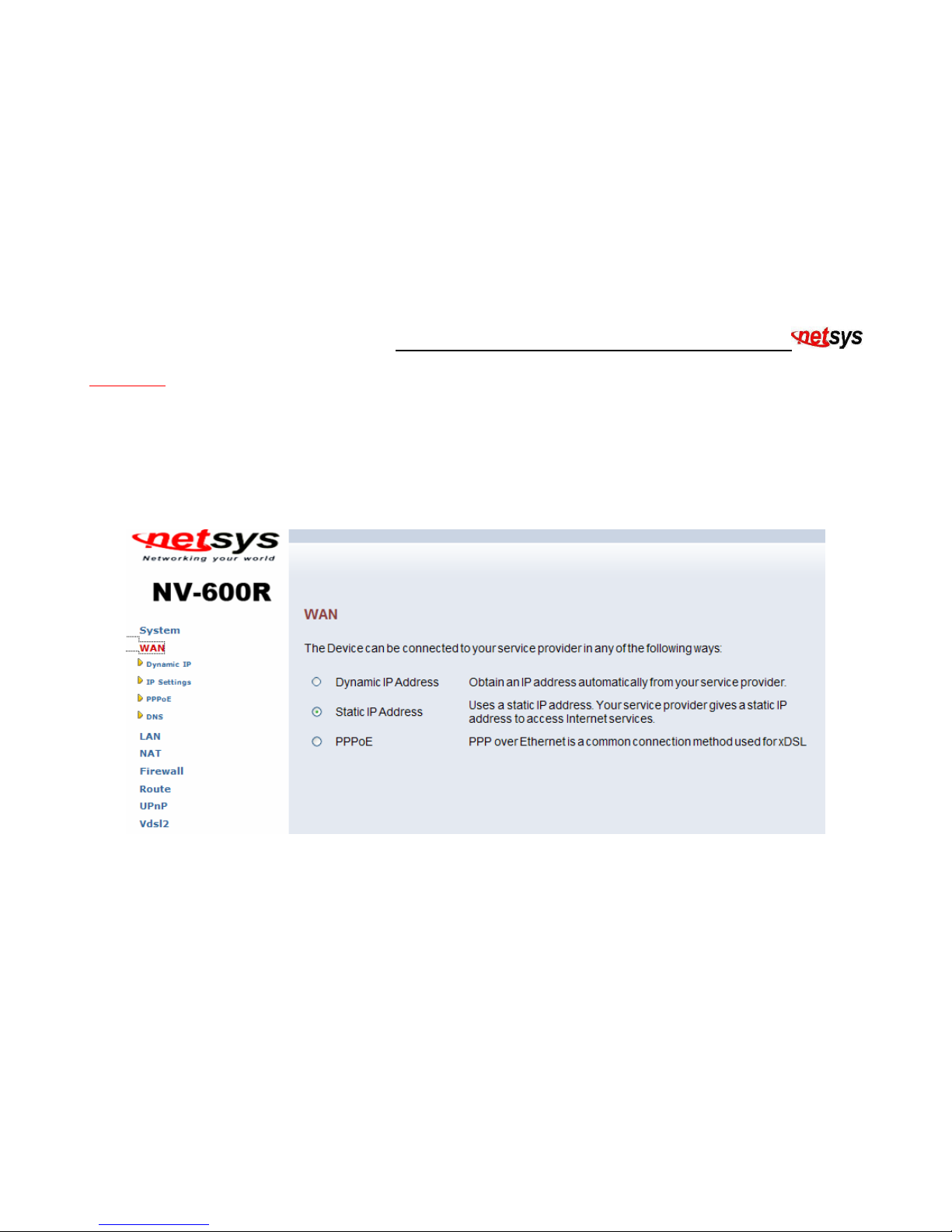
8.2.4 WAN
The WAN settings can be viewed in the left navigation bar of NV-600R only. The following are the options available under
WAN, as shown Figure 8.2.4:
• Dynamic IP
• IP Settings
• PPPoE
• DNS
Figure 8.2.4 WAN Setting in Left Navigator Bar
Page 63
NV600L/R VDSL2 CO&CPE Router USER’S MANUAL Ver.A15
62
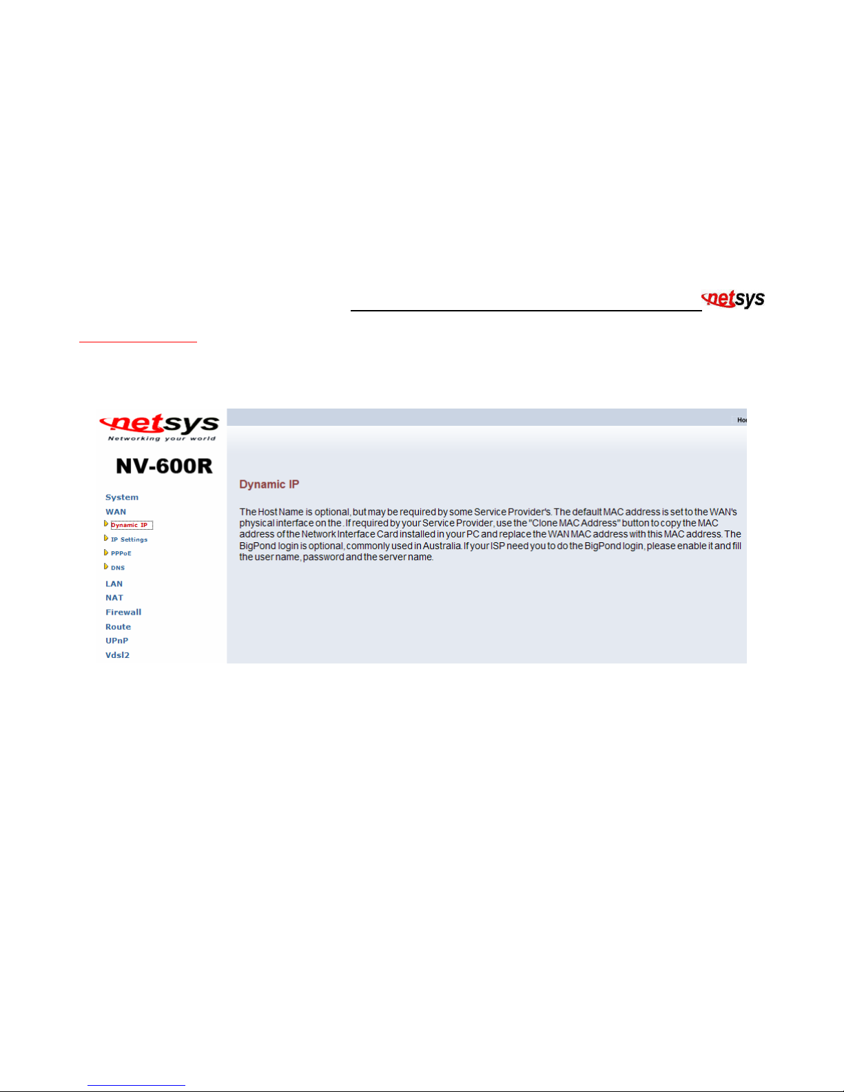
8.2.4.1 Dynamic IP
To configure the WAN interface to dynamically obtain an IP Address, click on the Dynamic IP link in the left navigation bar.
A screen is displayed as shown in Figure 8.2.4.1.
Figure 8.2.4.1 Dynamic IP Configuration
The screen contains the following details:
• Click APPLY to save the information that has been entered.
• Click CANCEL to exit from this page.
Page 64
NV600L/R VDSL2 CO&CPE Router USER’S MANUAL Ver.A15
63
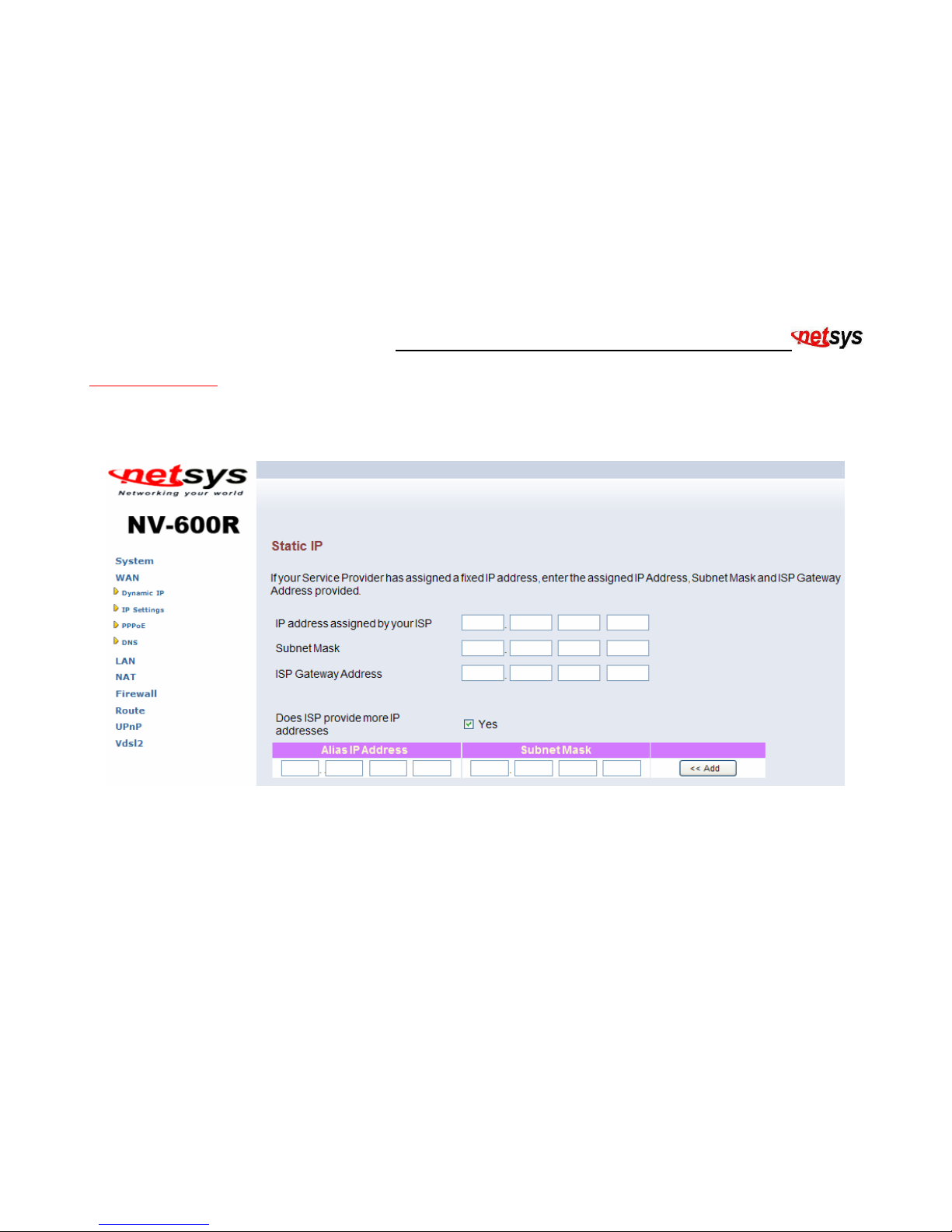
8.2.4.2 IP Settings
To configure the WAN interface to use a Static IP Address, click on the Static IP link in the left navigation bar. A screen is
displayed as shown in Figure 8.2.4.2.
Figure 8.2.4.2 Static IP Configuration
Page 65
NV600L/R VDSL2 CO&CPE Router USER’S MANUAL Ver.A15
64
The screen contains the following details:
Fields in Static IP
Field Description
IP Address assigned by your ISP Enter the IP Address of NV-600L/R.
Subnet Mask Enter the Subnet Mask of NV-600L/R.
ISP Gateway Address Enter the Gateway address of the NV-600L/R.
Does ISP provide more IP Address
Provides more IP Addresses of the WAN interface. Select the check box
to enable this option. A screen is displayed as shown in Figure 41. Click
Add to add IP Address and Subnet Mask.
IP Pool Starting Address
Enter the starting IP Pool Address.
IP Pool Ending Address
Enter the ending IP Pool Address.
Lease Time
Enter the Lease Time from half hour to two weeks.
Local Domain Name
Enter the Local Domain Name but is optional.
• Click APPLY to save the information that has been entered.
• Click CANCEL to exit from this page without saving the changes.
Page 66
NV600L/R VDSL2 CO&CPE Router USER’S MANUAL Ver.A15
65
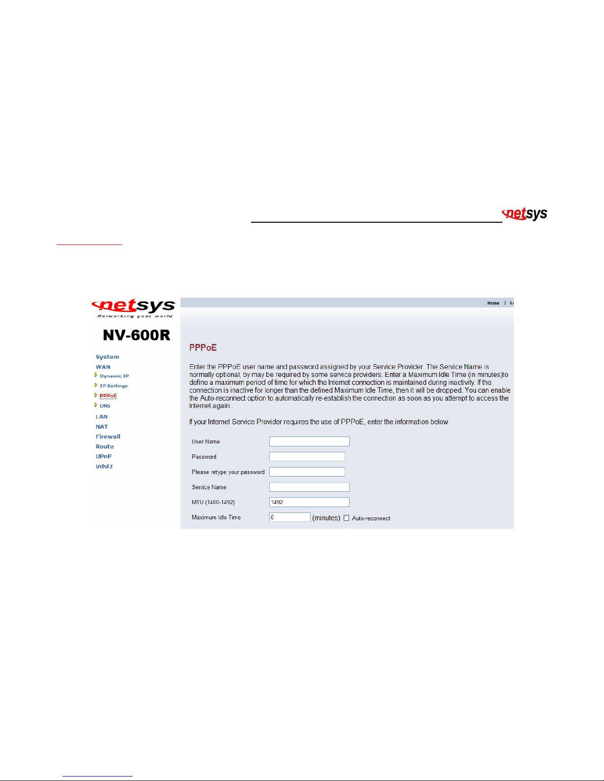
8.2.4.3 PPPoE
To configure the WAN interface to use PPPoE, click on the PPPoE link in the left navigation bar. A screen is displayed as
shown in Figure 8.2.4.3.
Figure 8.2.4.3 PPPoE Configuration
Page 67
NV600L/R VDSL2 CO&CPE Router USER’S MANUAL Ver.A15
66
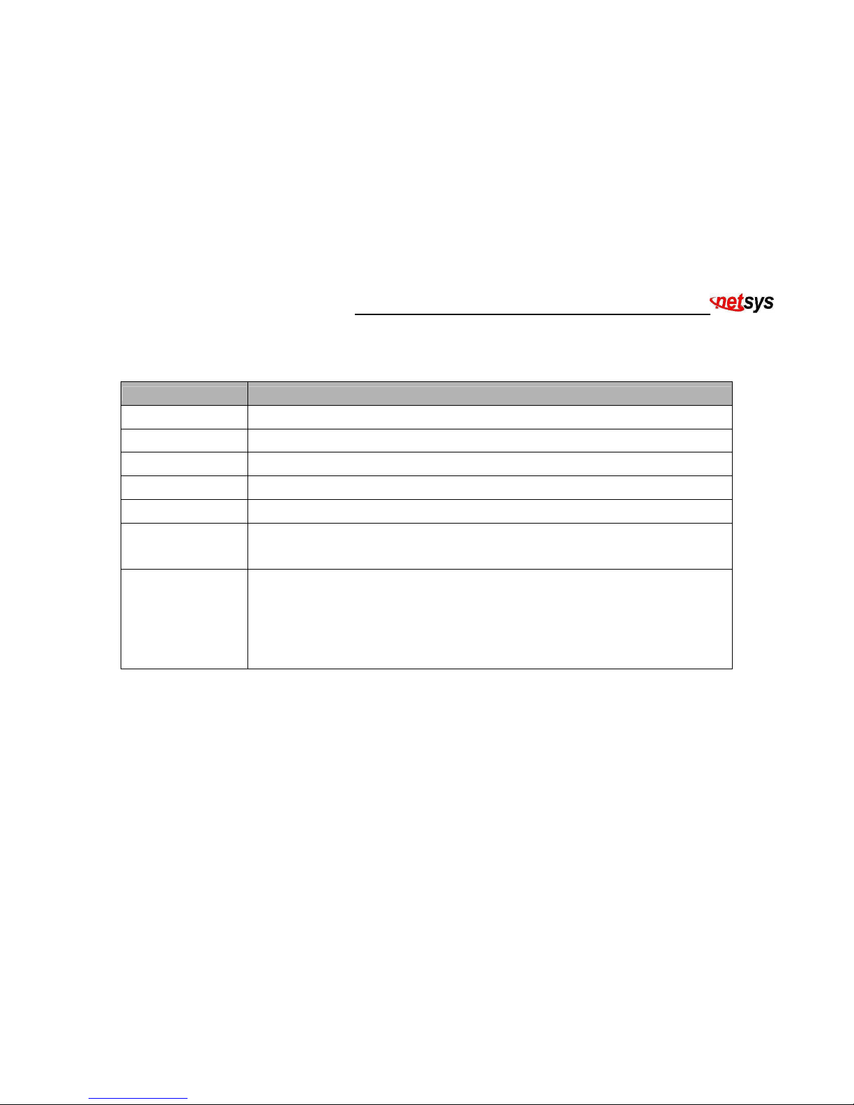
The screen contains the following details:
Fields in PPPoE
Field Description
User Name Enter a name to use the PPPoE session.
Password Enter the password of the login user.
Retype Password Enter the password again to reconfirm.
Service Name Enter a service name.
Field Description
MTU
Enter the maximum connection units of the PPPoE. The MTU range is 1400 to 1492
bytes. By default, it is 1492.
Maximum Idle Time
This is the period of time required to keep the connection alive if no packets are
transmitted. If no packets are transmitted between LAN port and WAN port or between
NV-600L/R and WAN, the connection is disconnected after the 'Maximum idle time.
If the Auto-reconnect check box is selected, the PPP connection is re-established if there
is some data that is received from the upper layers to be transmitted on this link.
• Click APPLY to save the information that has been entered.
• Click CANCEL to exit from this page without saving the changes.
Page 68
NV600L/R VDSL2 CO&CPE Router USER’S MANUAL Ver.A15
67
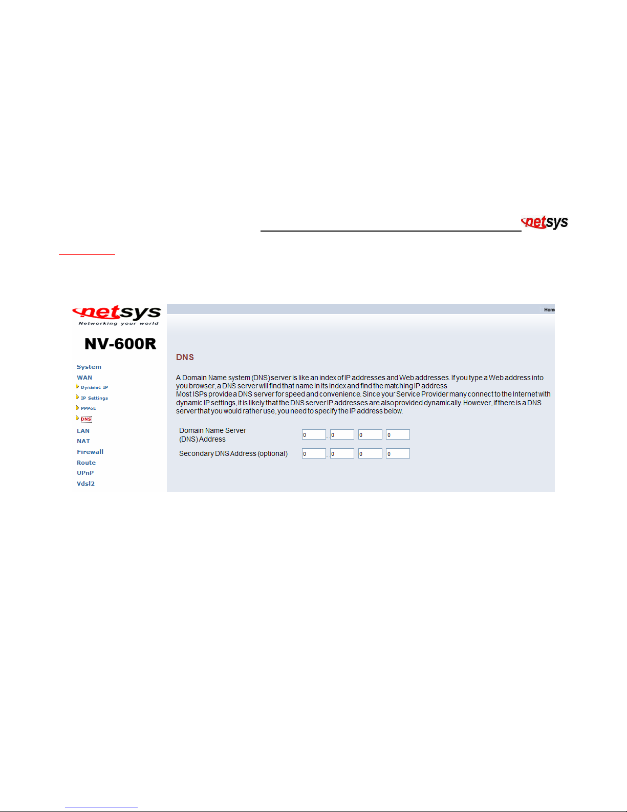
8.2.4.4 DNS
To configure the DNS address, click on the DNS link in the left navigation bar. A screen is displayed as shown in
Figure 8.2.4.4:
Figure 8.2.4.4 DNS Configuration
Page 69
NV600L/R VDSL2 CO&CPE Router USER’S MANUAL Ver.A15
68
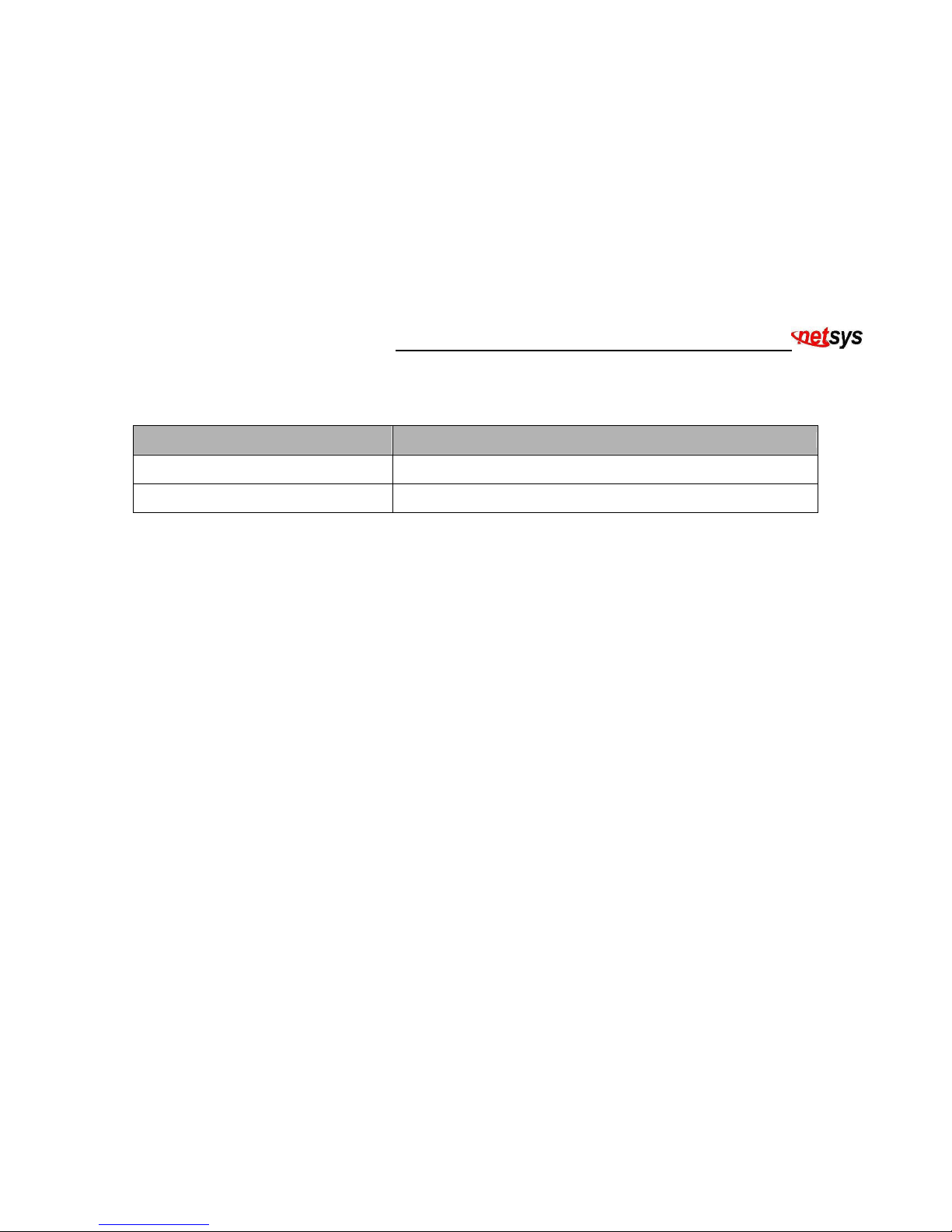
The screen contains the following details:
Fields in DNS
Field Description
Domain Name Server(DNS) Address Enter the DNS address of the primary DNS server.
Secondary DNS Address(optional) Enter the address of the secondary DNS server, if available.
• Click APPLY to save the information that has been entered.
• Click CANCEL to exit from this page without saving the changes.
Page 70
NV600L/R VDSL2 CO&CPE Router USER’S MANUAL Ver.A15
69
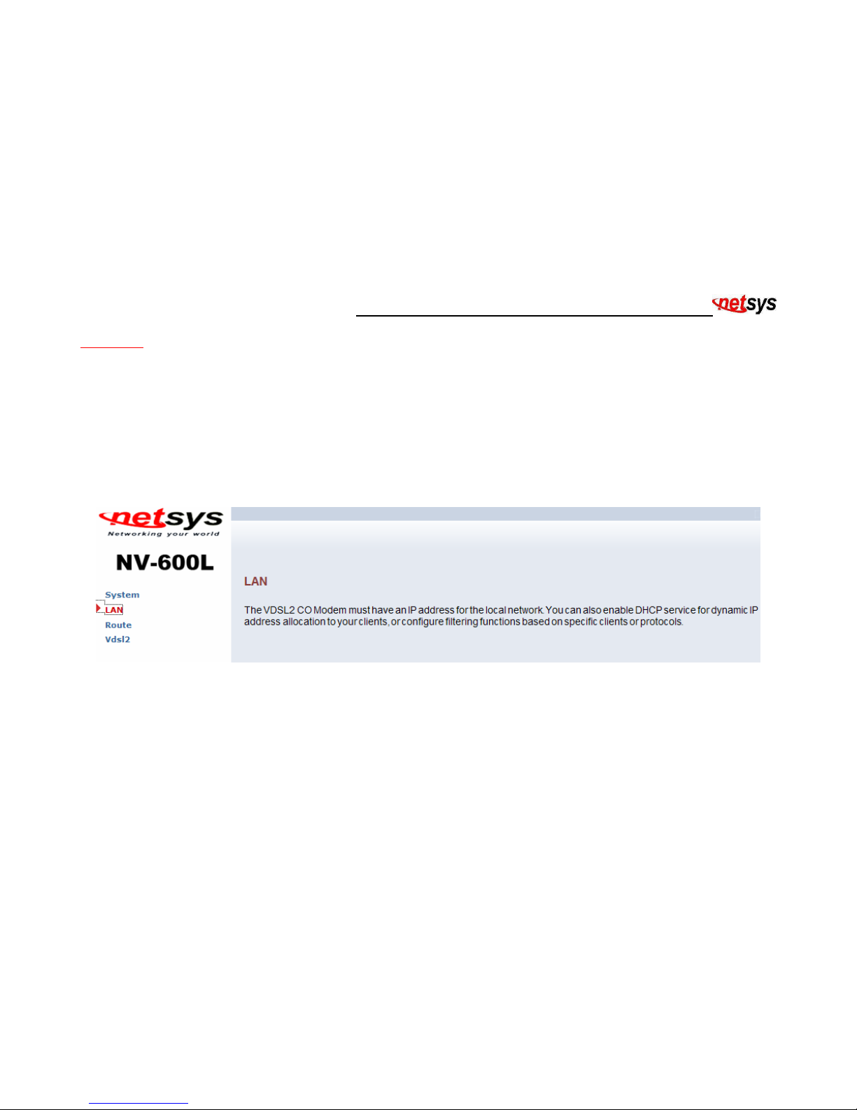
8.2.5 LAN
The LAN Setting can be viewed in the left navigation bar. The following are the options available under LAN, as shown in
Figure 8.2.5:
• LAN Settings
• DHCP Client List
• LAN Switch Port Setting
• LAN Port Status
Figure 8.2.5 LAN in Left Navigator Bar
Page 71
NV600L/R VDSL2 CO&CPE Router USER’S MANUAL Ver.A15
70
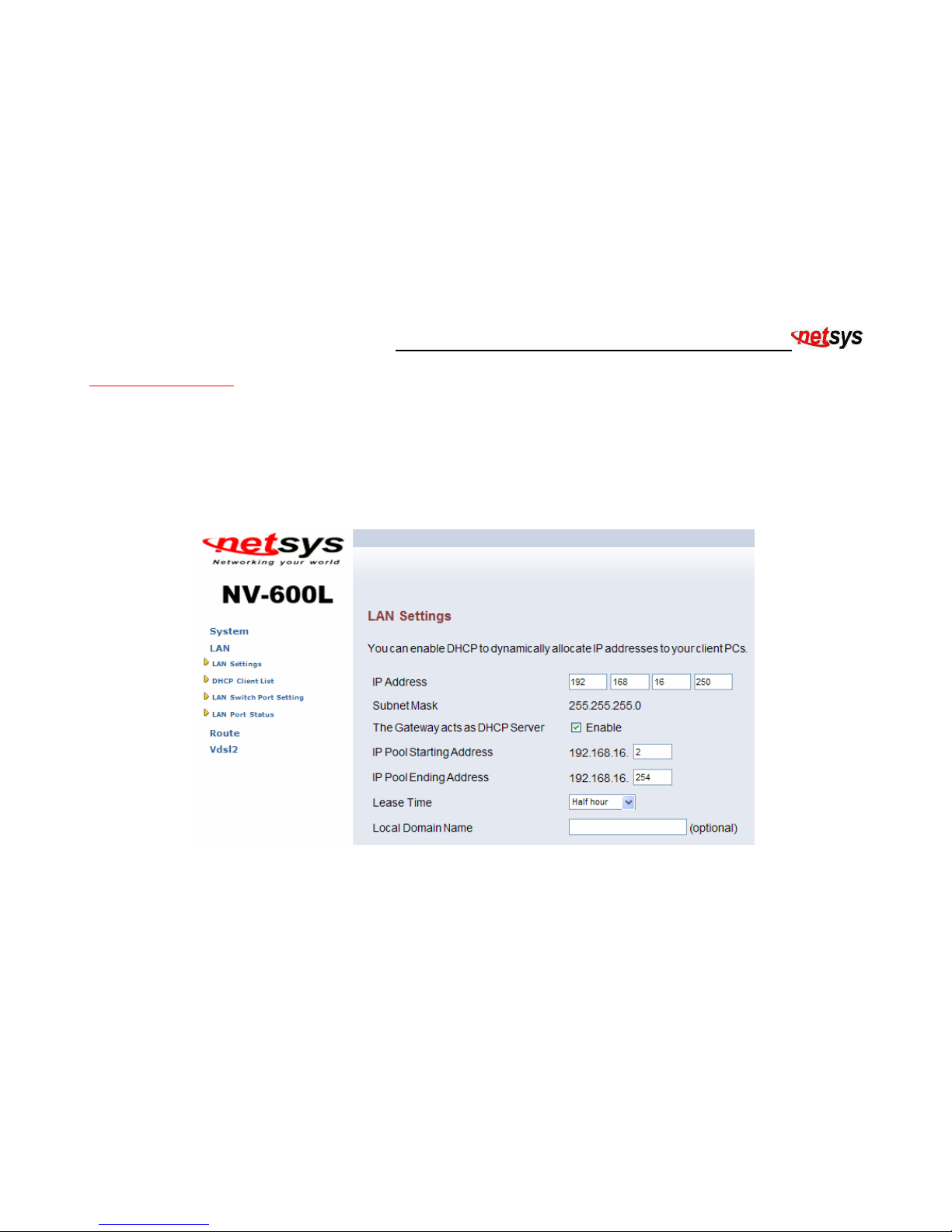
8.2.5.1 LAN Settings
Attention: For the NV-600L/R it is recommended to select a simple IP setting suitable to controlled lab environments. Set a
static IP address and don’t use DHCP. The required steps are explained in Chapter 4.4.1 on Page 21!
To configure the LAN interface, click on the LAN Settings link in the left navigation bar. A screen is displayed as shown in
Figure 8.2.5.1 in case of the NV-600 kit.
Figure 8.2.5.1 LAN Settings
Page 72
NV600L/R VDSL2 CO&CPE Router USER’S MANUAL Ver.A15
71
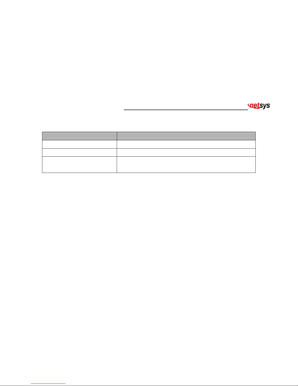
The screen contains the following details:
Fields in LAN Settings
Field Description
IP Address Enter the LAN interface IP Address of NV-600L/R.
Subnet Mask Enter the LAN Subnet Mask of NV-600L/R.
The Gateway acts as DHCP Server
Enable or disables the DHCP Server of the NV-600L/R. Select the
check-box to enable this option.
• Click APPLY to save the information that has been entered.
• Click CANCEL to exit from this page without saving the changes.
Page 73
NV600L/R VDSL2 CO&CPE Router USER’S MANUAL Ver.A15
72
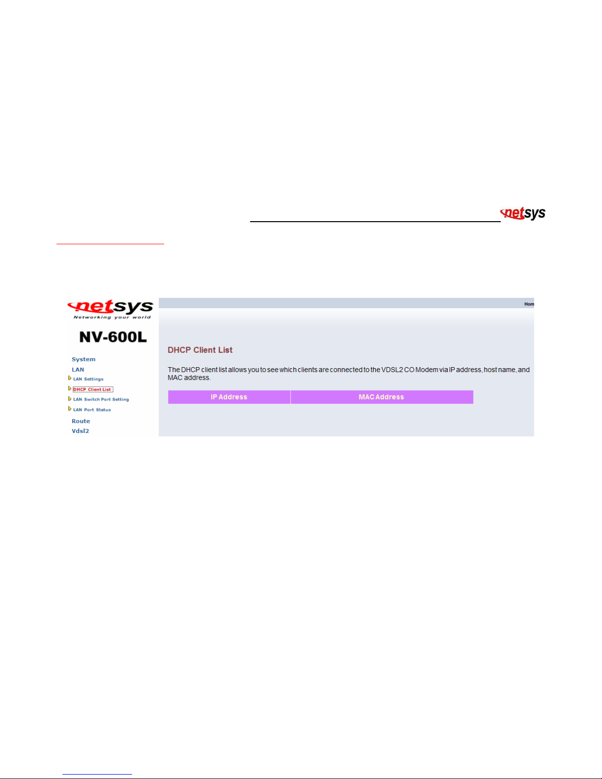
8.2.5.2 DHCP Client List
To view the DHCP client list, click on the DHCP Client List link in the left navigation bar. A screen is displayed to list all
DHCP client connection with IP Address and MAC Address as shown in Figure 8.2.5.2.
Figure 8.2.5.2 DHCP Client List
Page 74
NV600L/R VDSL2 CO&CPE Router USER’S MANUAL Ver.A15
73
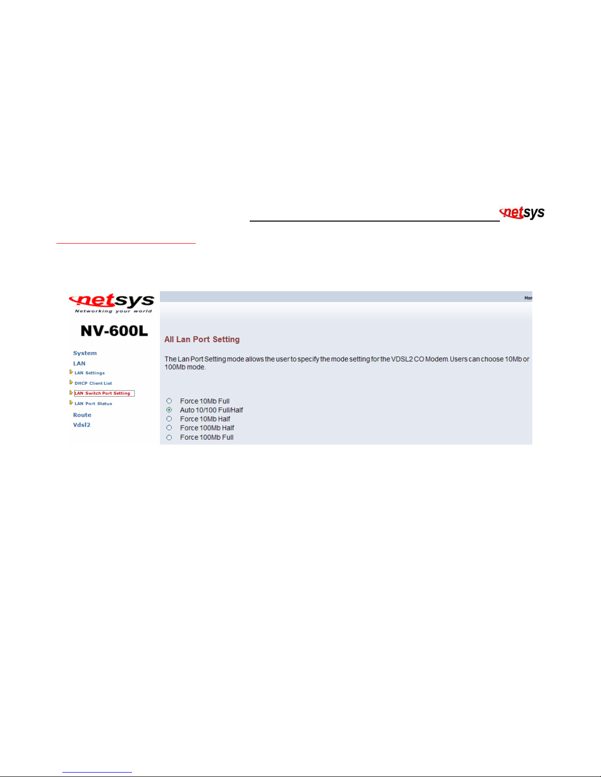
8.2.5.3 LAN Switch Port Setting
To view the All LAN Port Setting, click on the All Lan Port Setting link in the left navigation bar. A screen is displayed to all
LAN Port Setting as shown in Figure 8.2.5.3.
Figure 8.2.5.3 DHCP Client List
Page 75
NV600L/R VDSL2 CO&CPE Router USER’S MANUAL Ver.A15
74
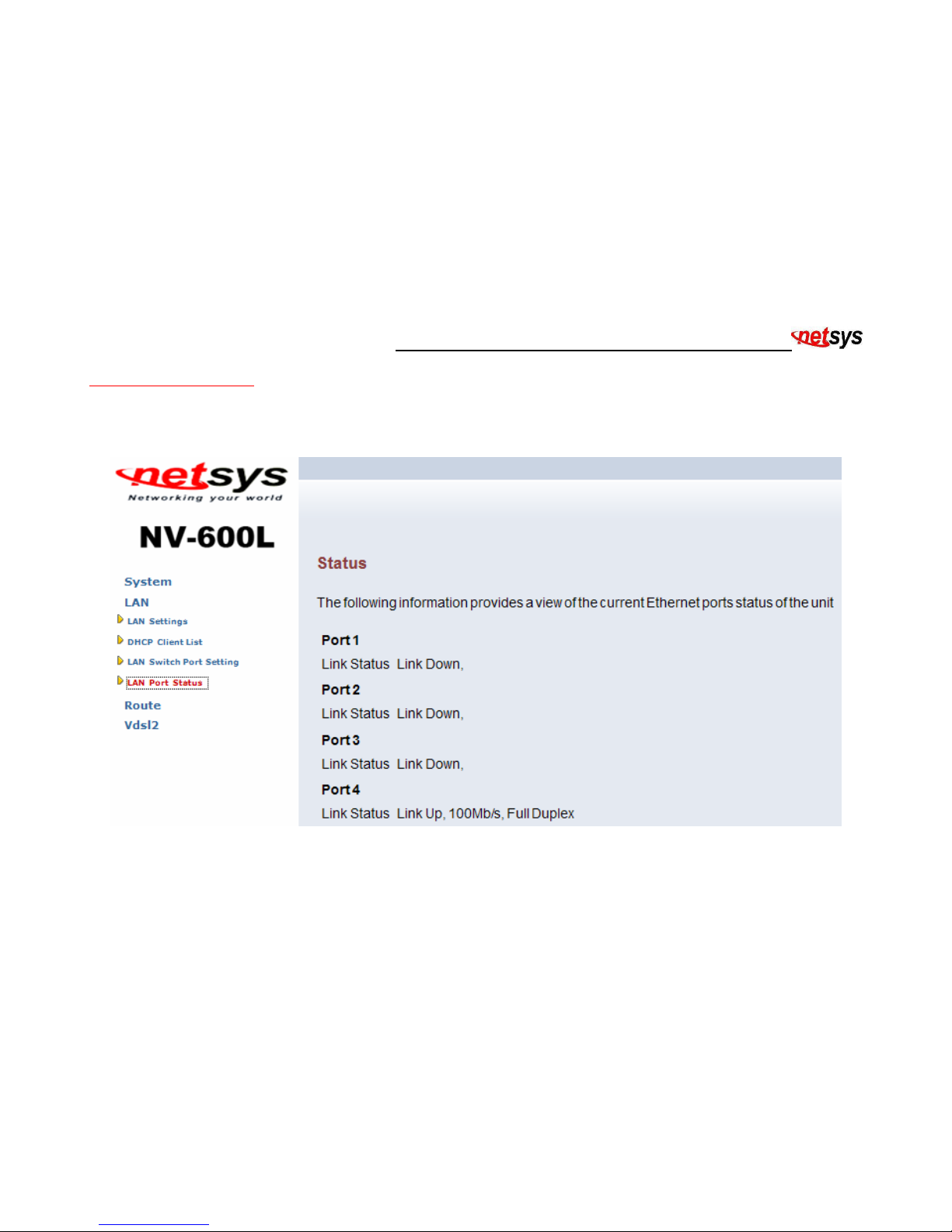
8.2.5.4 LAN Port Status
The following information provides a view of the current Ethernet ports status of the unit
Figure 8.2.5.4 LAN Port Status
Page 76
NV600L/R VDSL2 CO&CPE Router USER’S MANUAL Ver.A15
75
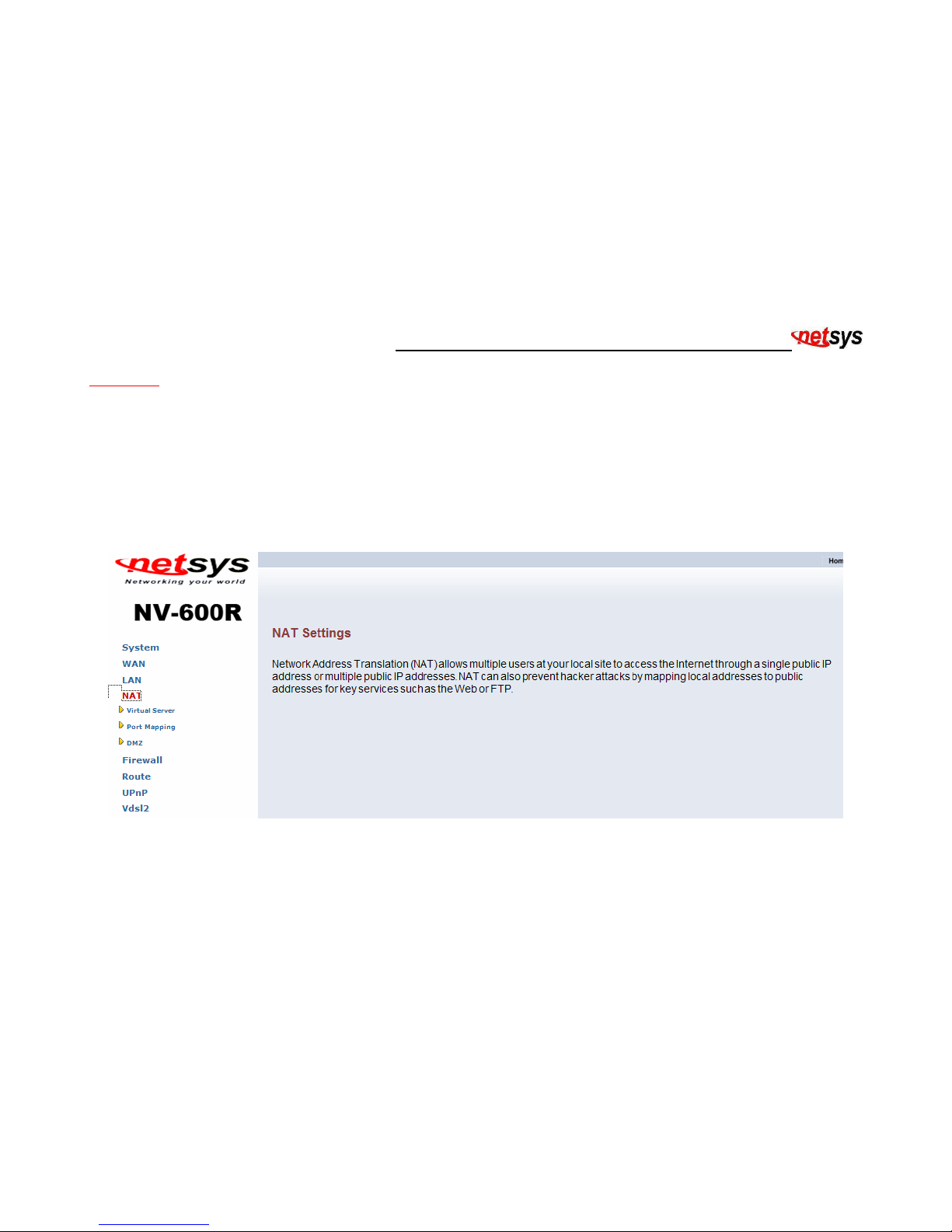
8.2.6 NAT
The NAT Settings can be viewed in the left navigation bar of NV-600R only. The following are the options available under
NAT, as shown in Figure 8.2.6:
• Virtual Server
• Port Mapping
• DMZ
Figure 8.2.6 NAT in Left Navigator Bar
Page 77
NV600L/R VDSL2 CO&CPE Router USER’S MANUAL Ver.A15
76
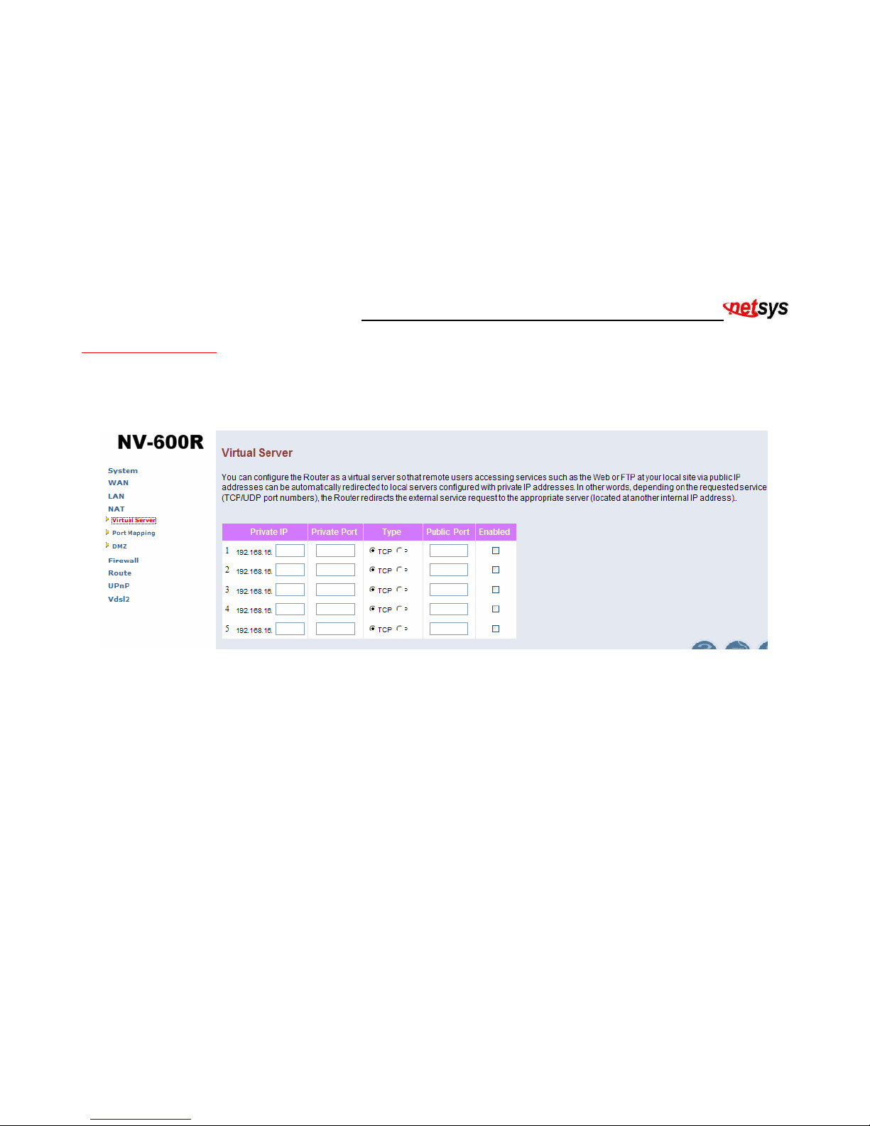
8.2.6.1 Virtual Server
To configure virtual server, click on the Virtual Server link in the left navigation bar. A screen is displayed as shown in
Figure 8.2.6.1:
Figure 8.2.6.1 Virtual Server Configuration
Page 78
NV600L/R VDSL2 CO&CPE Router USER’S MANUAL Ver.A15
77
The screen contains the following details:
Fields in Virtual Server
Field Description
Private IP Enter a private IP Address of specified entry.
Private Port Enter a private Port number of the specified entry.
Type Select virtual server protocol type of the specified entry.
Public Port Enter a public port number of the internet user to access the virtual server.
Enabled Enable the specified entry of the virtual server.
• Click APPLY to save the information that has been entered.
• Click CANCEL to exit from this page without saving the changes.
Page 79
NV600L/R VDSL2 CO&CPE Router USER’S MANUAL Ver.A15
78
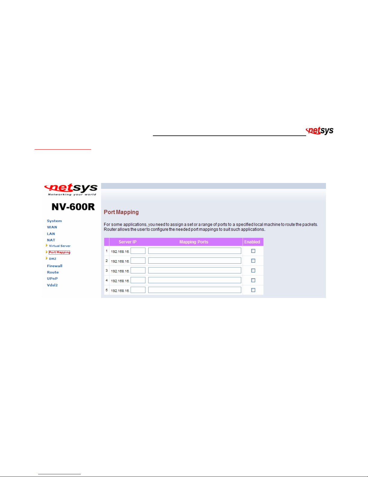
8.2.6.2 Port Mapping
To configure Port Mapping, click on the Port Mapping link in the left navigation bar. A screen is displayed as shown in
Figure 8.2.6.2:
Figure 8.2.6.2 Port Mapping Configuration
Page 80
NV600L/R VDSL2 CO&CPE Router USER’S MANUAL Ver.A15
79
The screen contains the following details:
Fields in Port Mapping
Field Description
Server IP Enter the IP Address of a specified local machine.
Mapping Port Assign a range of port or specific port number to route the packets.
Enabled Enable a specified entry of the Port Mapping.
• Click APPLY to save the information that has been entered.
• Click CANCEL to exit from this page without saving the changes.
Page 81
NV600L/R VDSL2 CO&CPE Router USER’S MANUAL Ver.A15
80
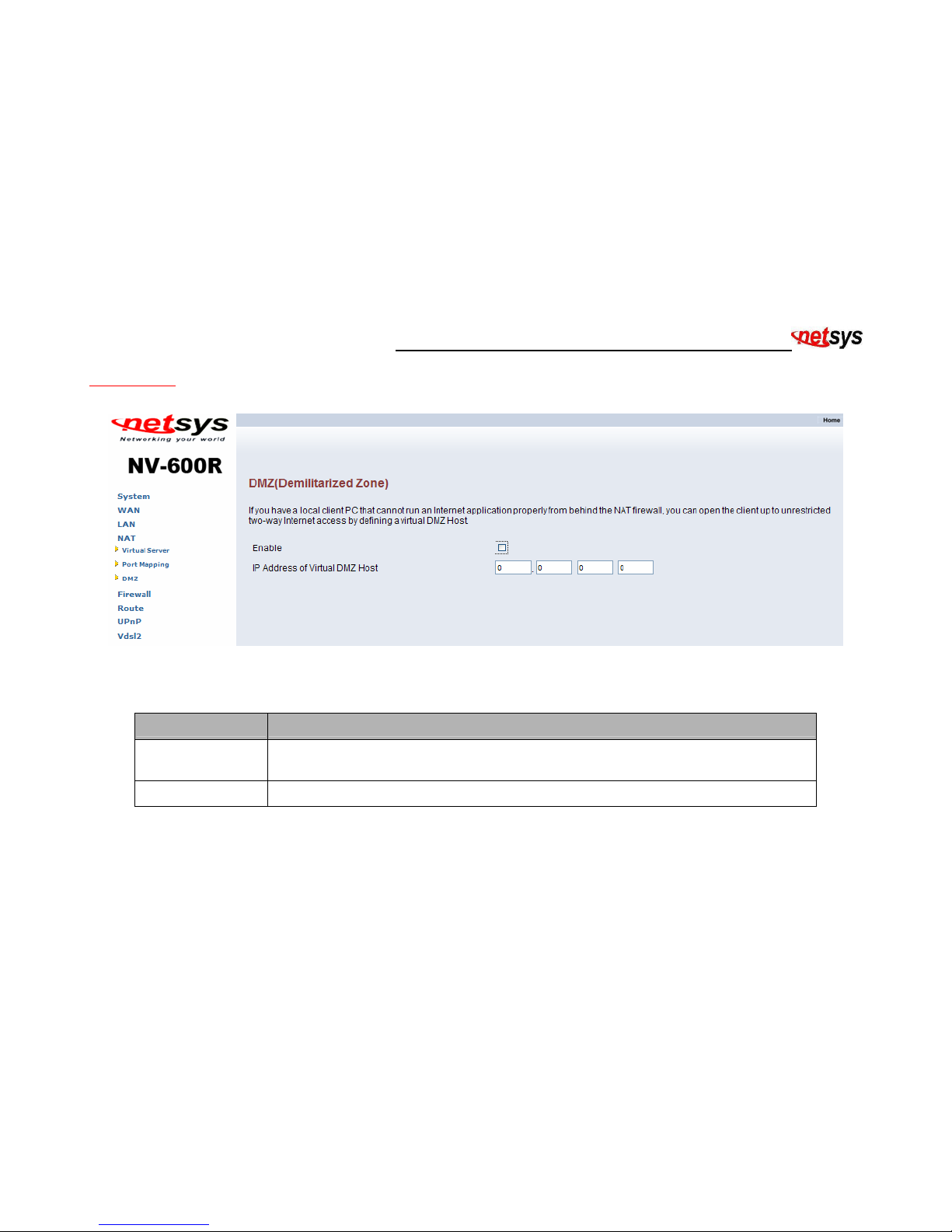
8.2.6.3 DMZ
To configure the DMZ, click on the DMZ link in the left navigation bar. A screen is displayed as shown in Figure 8.2.6.3:
Figure 8.2.6.3 DMZ Configuration
The screen contains the following details:
Fields in DMZ
Field Description
Enable
Enable or disable the DMZ setting of NV-600L/R. Select the check box to enable this
option.
IP Address Enter IP Address of the DMZ host.
• Click APPLY to save the information that has been entered.
• Click CANCEL to exit from this page without saving the changes.
Page 82
NV600L/R VDSL2 CO&CPE Router USER’S MANUAL Ver.A15
81
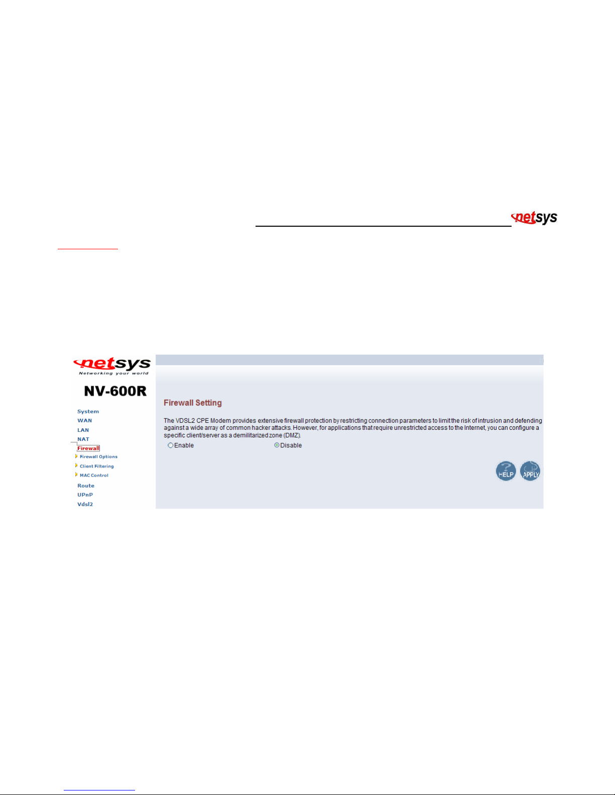
8.2.7 Firewall
The Firewall Settings can be viewed in the left navigation bar of NV-600R only. The following are the options available
under Firewall, as shown in Figure 8.2.7:
• Firewall Options
• Client Filter MAC Control
• MAC Control
Figure 8.2.7 Firewall in Left Navigator Bar
Page 83
NV600L/R VDSL2 CO&CPE Router USER’S MANUAL Ver.A15
82
8.2.7.1 Firewall Options
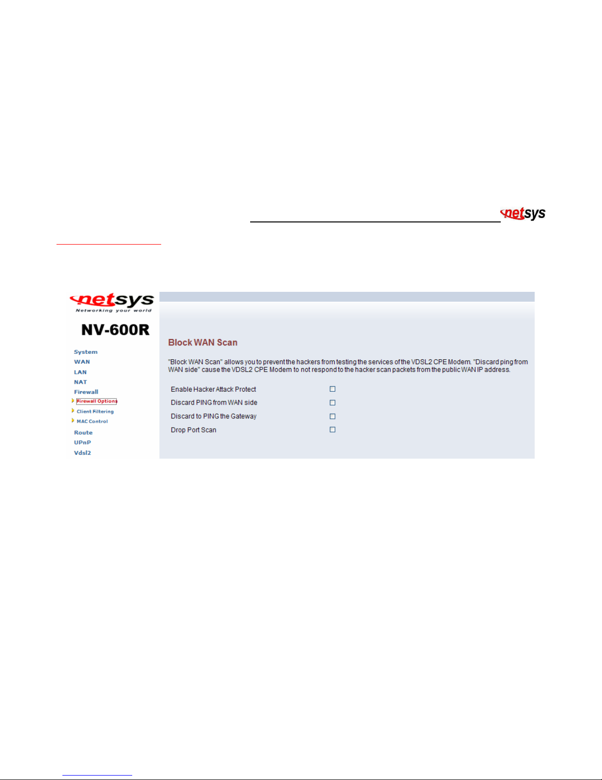
To enable the firewall options, click on the Firewall Options link in the left navigation bar. A screen is displayed as shown
in Figure 8.2.7.1:
Figure 8.2.7.1 Firewall Options Configuration
Page 84
NV600L/R VDSL2 CO&CPE Router USER’S MANUAL Ver.A15
83
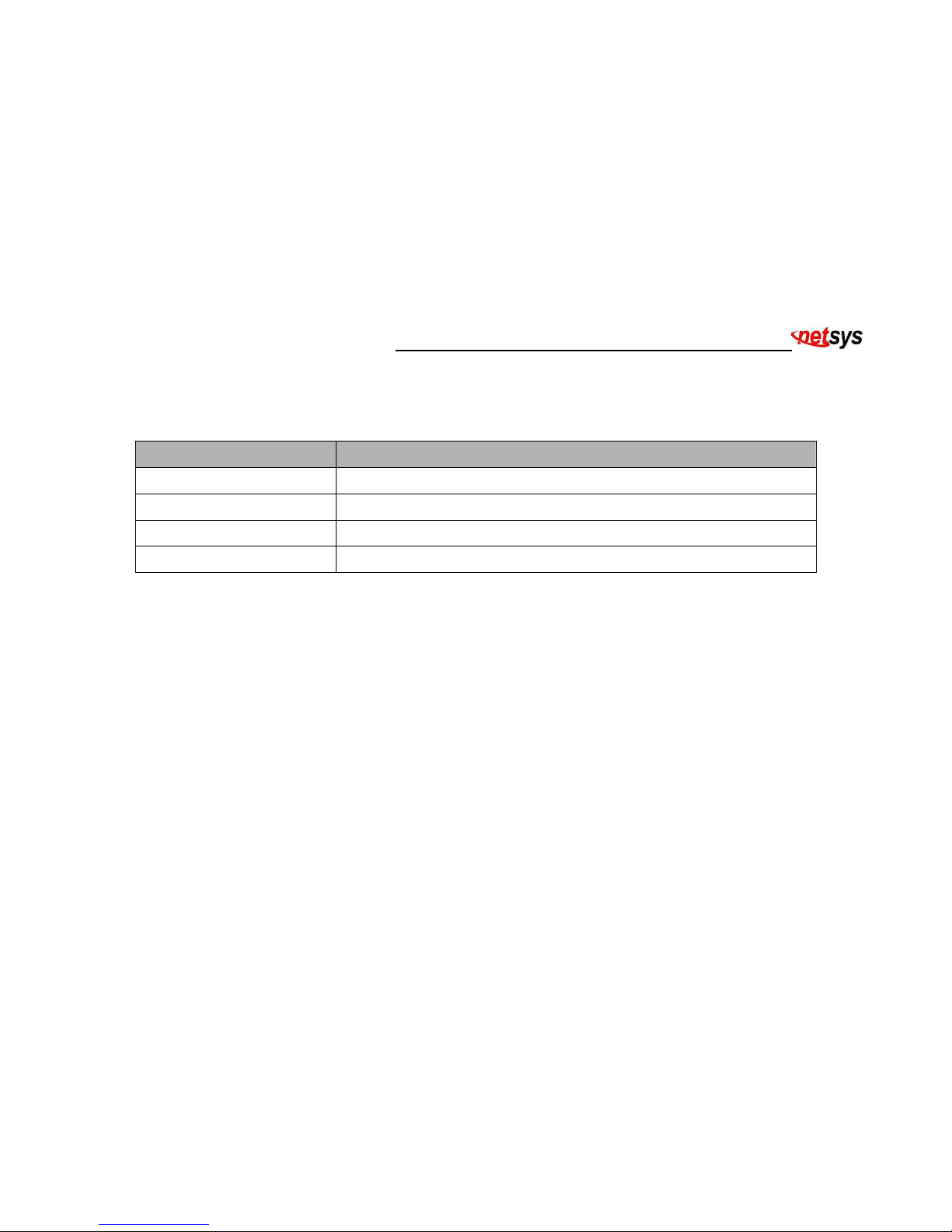
The screen contains the following details:
Fields in Firewall Options
Field Description
Enable Hacker Attack Protect Select the check box to log and drop all the hacker attack events.
Discard PING from WAN Select the check box to drop all PING from the WAN side.
Discard PING the Gateway Select the check box to drop all PING to NV-600L/R packet for the LAN side.
Drop Port Scan Select the check box to drop all the port scan packets.
• Click APPLY to save the information that has been entered.
• Click CANCEL to exit from this page without saving the changes.
Page 85
NV600L/R VDSL2 CO&CPE Router USER’S MANUAL Ver.A15
84
8.2.7.2 Client Filtering
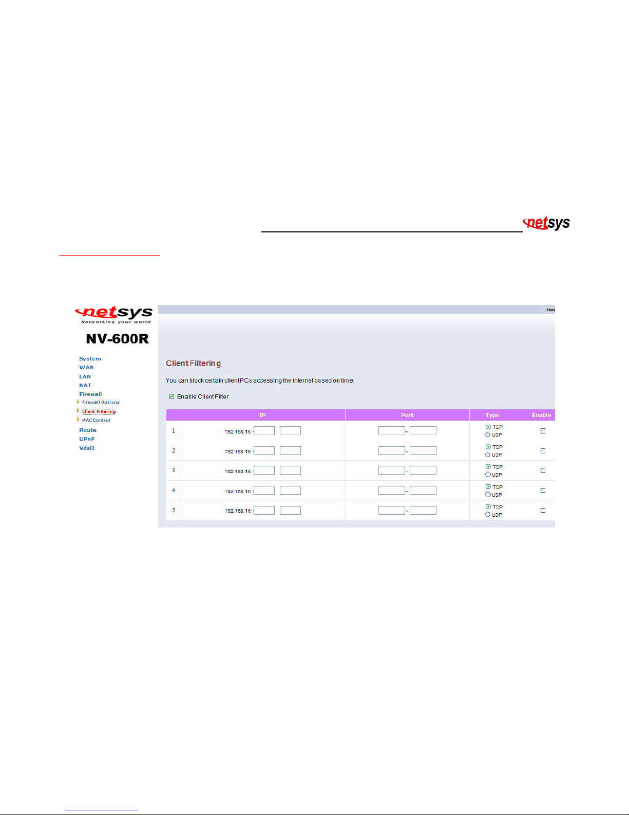
To enable Client Filter, click on the Client Filter link in the left navigation bar. A screen is displayed as shown in
Figure 8.2.7.2.
Figure 8.2.7.2 Client Filter Configuration
The screen contains the following details:
Page 86
NV600L/R VDSL2 CO&CPE Router USER’S MANUAL Ver.A15
85
Fields in Client Filter
Field Description
Enable Client Filter
Enable or disable the Client Filter feature of VDSL2 CO&CPE ROUTER. Select the
check box to enable this option.
IP
Enter the filter IP Address range of the local machines under VDSL2 CO&CPE
ROUTER.
Port
Enter the filter Port number range of the local machines under VDSL2 CO&CPE
ROUTER.
Type Select TCP or UDP to filter the protocol type packets from the local machines.
Enable Provides more IP Addresses of the WAN interface.
• Click APPLY to save the information that has been entered.
• Click CANCEL to exit from this page without saving the changes.
Page 87
NV600L/R VDSL2 CO&CPE Router USER’S MANUAL Ver.A15
86
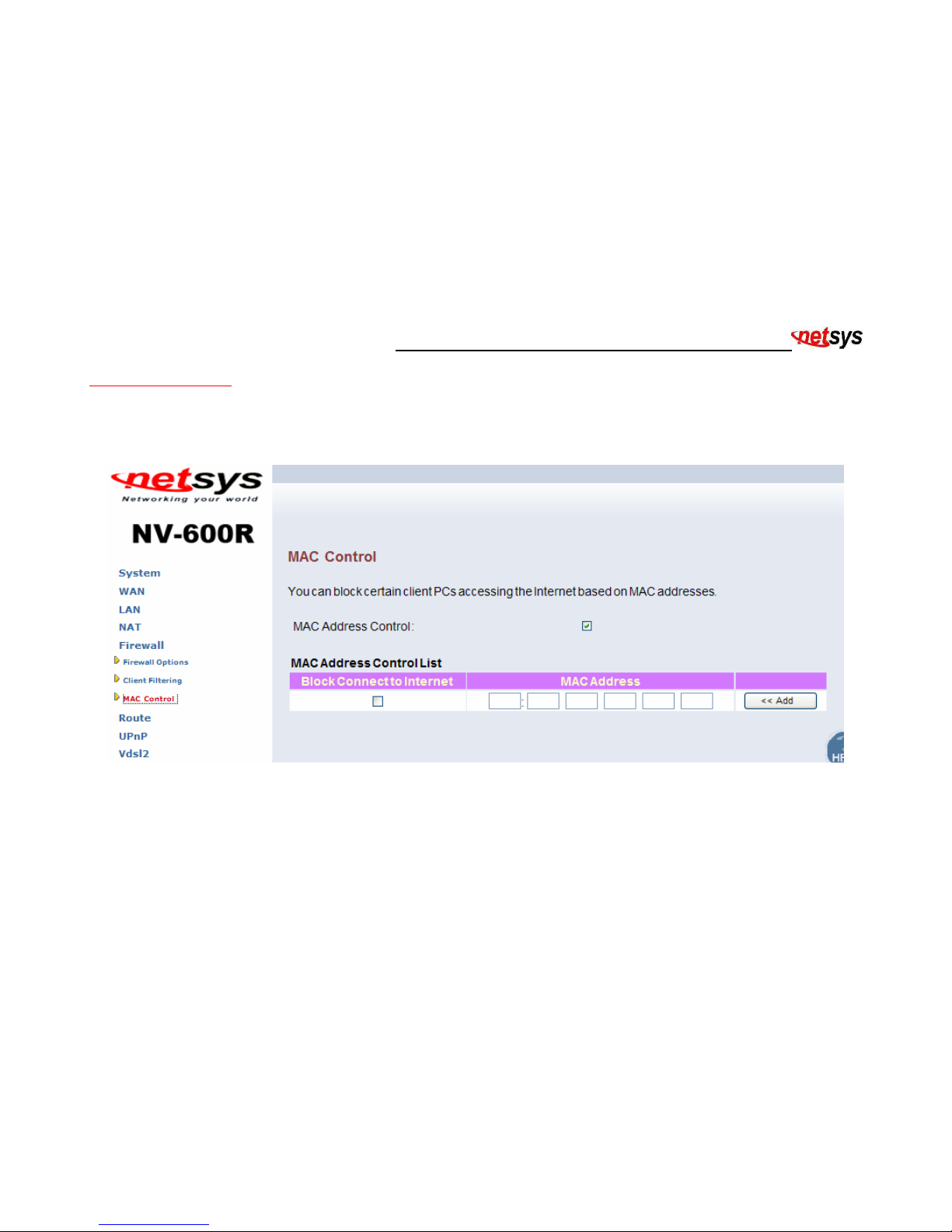
8.2.7.3 MAC Control
To configure MAC Control, click on the MAC Control link in the left navigation bar. A screen is displayed as shown in
Figure 8.2.7.3
Figure 8.2.7.3 MAC Control Configuration
Page 88
NV600L/R VDSL2 CO&CPE Router USER’S MANUAL Ver.A15
87
The screen contains the following details:
Fields in MAC Control
Field Description
MAC Address Control Enable or disable the MAC address control.
Block Connection to Internet
Enable or disable block status. If the check box is selected, it blocks the
specified MAC address.
MAC Address Assign the blocking MAC address for local machine.
• Click APPLY to save the information that has been entered.
• Click CANCEL to exit from this page without saving the changes.
Page 89
NV600L/R VDSL2 CO&CPE Router USER’S MANUAL Ver.A15
88
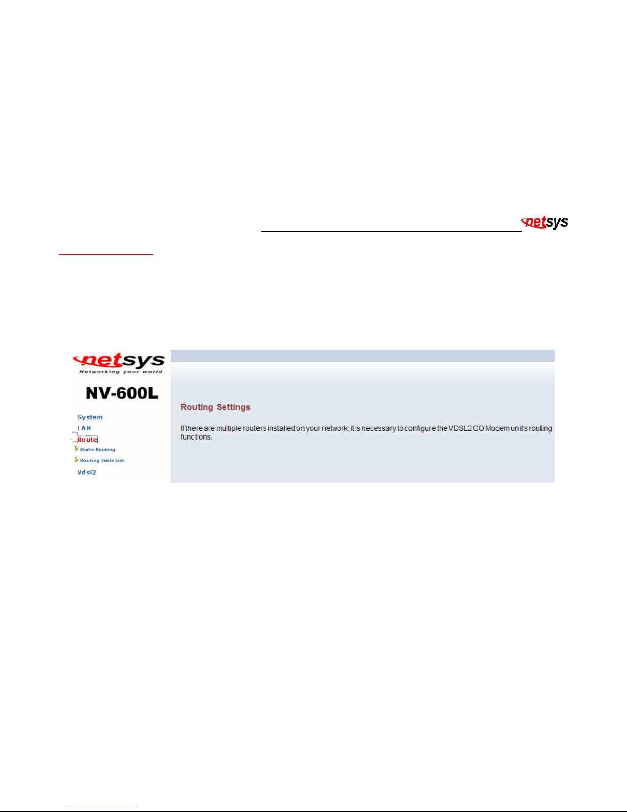
8.2.8 Route Settings
The Route Settings can be viewed in the left navigation bar. The following are the options available under Route, as
shown in Figure 8.2.8:
• Static Routing
• Routing Table List
Figure 8.2.8 Route in Left Navigator Bar
Page 90
NV600L/R VDSL2 CO&CPE Router USER’S MANUAL Ver.A15
89
8.2.8.1 Static Routing
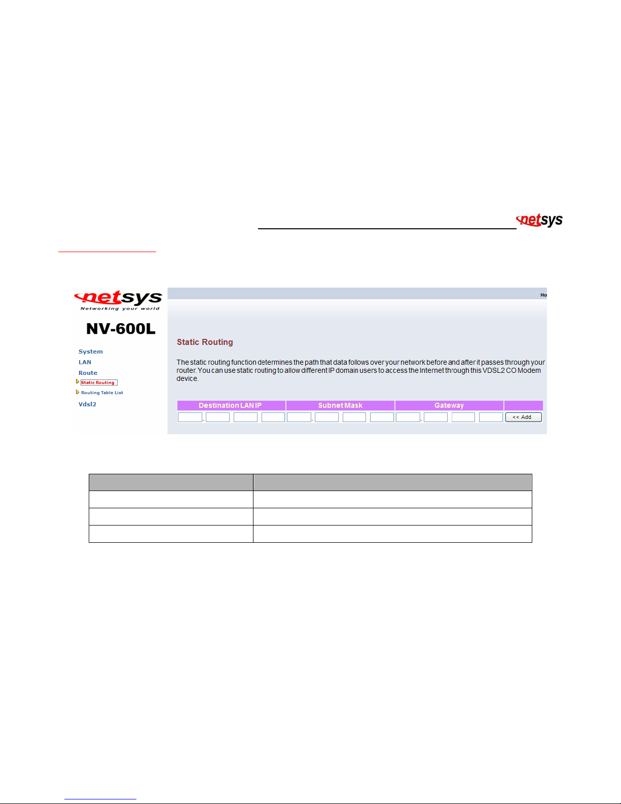
To setup Static Routing, click on the Static Routing link in the left navigation bar. A screen is displayed as shown in
Figure 8.2.8.1.
Figure 8.2.8.1 Static Routing Configuration
The screen contains the following details:
Fields in Static Routing
Field Description
Destination LAN IP Enter the IP Address of routing entry.
Subnet Mask Enter the Subnet Mask of routing entry.
Gateway Enter the Gateway address of routing entry.
• Click Add to add the information that has been entered.
Page 91
NV600L/R VDSL2 CO&CPE Router USER’S MANUAL Ver.A15
90
8.2.8.2 Routing Table List
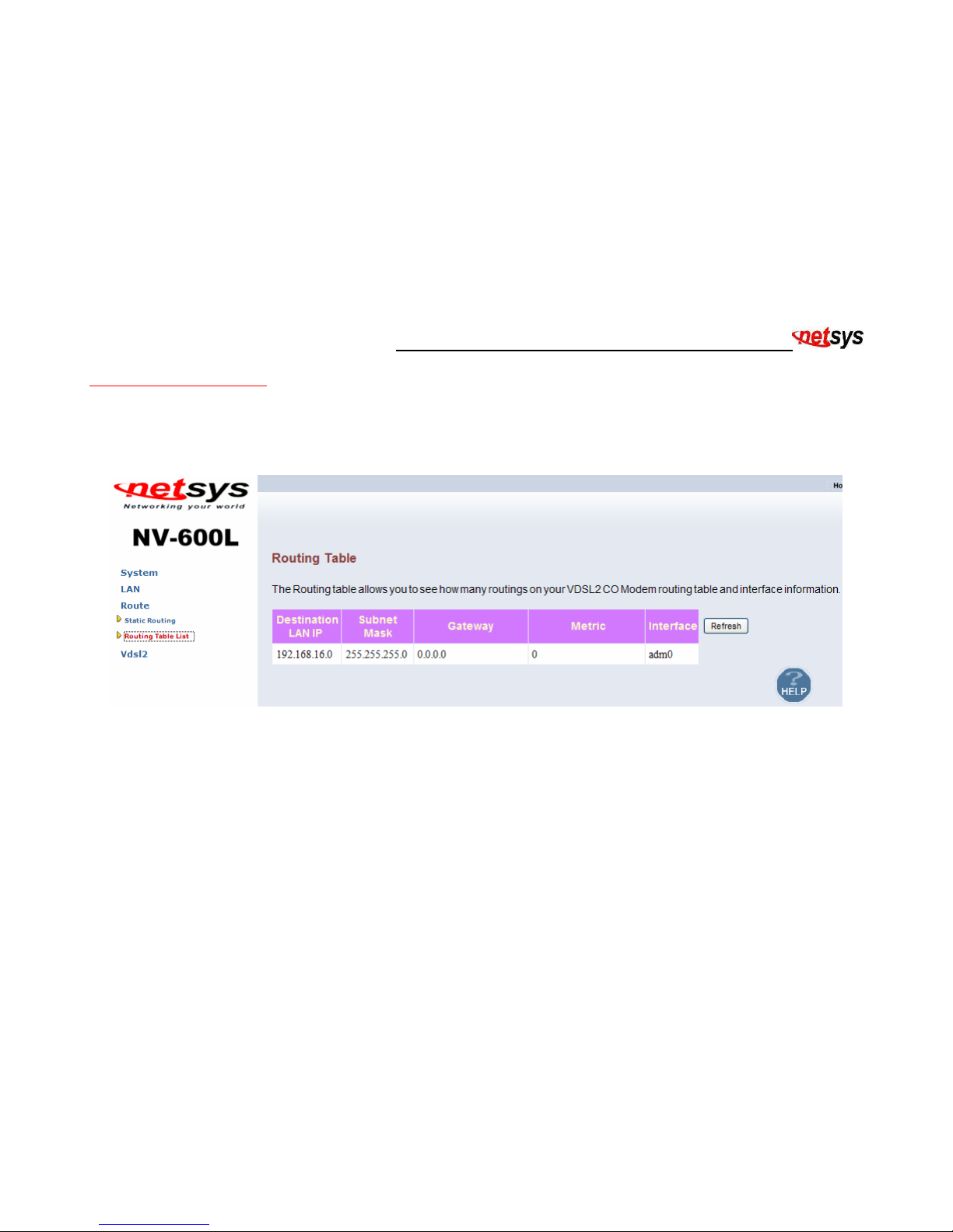
To view the Routing entry table list of NV-600L/R, click on the Routing Table by link in the left navigation bar.
A screen is displayed as shown in Figure 8.2.8.2.
Figure 8.2.8.2 Routing Table List
The screen contains the following details:
• Click Refresh to update currently routing list of the NV-600L/R.
Page 92
NV600L/R VDSL2 CO&CPE Router USER’S MANUAL Ver.A15
91
8.2.9 UPnP Setting
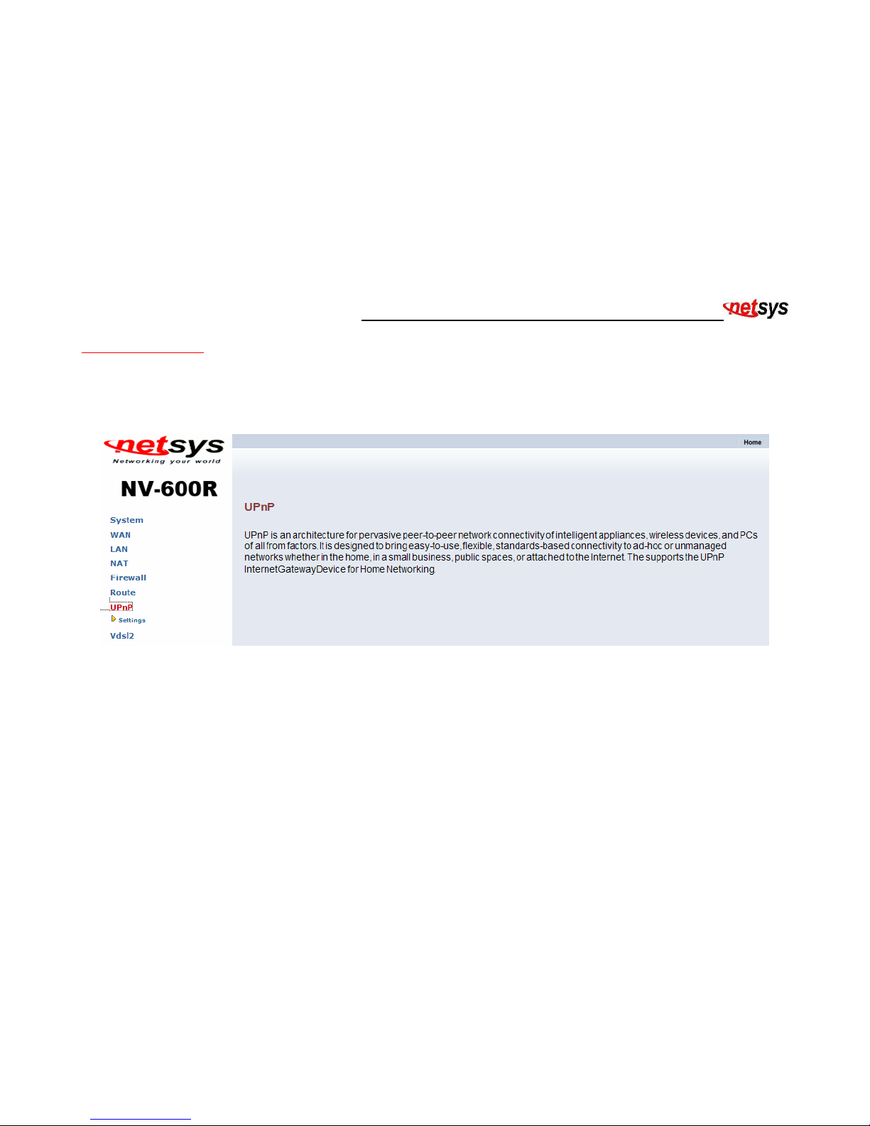
The UPnP Settings can be viewed in the left navigation bar of NV-600R only. The following are the options available
under UPnP, as shown in Figure 8.2.9.
Figure 8.2.9 UPnP in Left Navigator Bar
Page 93
NV600L/R VDSL2 CO&CPE Router USER’S MANUAL Ver.A15
92
8.2.9.1 Settings
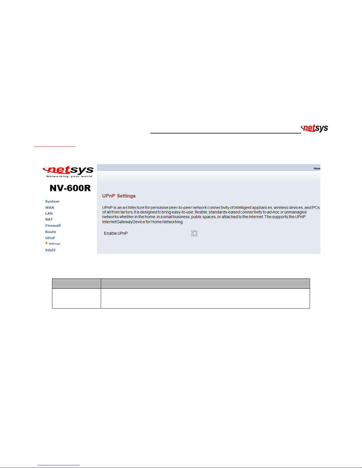
To enable or disable the UPnP Settings, click on the Settings link in the left navigation bar. A screen is displayed as
shown in Figure 8.2.9.1.
Figure 8.2.9.1 UPnP Configuration
The screen contains the following details:
Fields in UPnP Settings
Field Description
Enable UPnP
To enable or disable UPnP Setting. Select the check box to Enable or Disable the UPnP
function of SPEED-VDSL2 CO&CPE ROUTER.
• Click APPLY at any time during configuration to save the information that you have entered.
• Click CANCEL to exit from this page without saving the changes.
Page 94

NV600L/R VDSL2 CO&CPE Router USER’S MANUAL Ver.A15
93
Appendix A: Product Features & Specification
Features:
• Compliant with IEEE 802.3 & 802.3u Ethernet Standards
• Compliant with G993.2 VDSL2 standards
• Provides 4 x 10/100M auto-sensing RJ-45 Ethernet ports
• Supports Bandwidth setup with 100 Mbps VDSL RJ-11 ports
• POTS / ISDN Splitter port RJ-11 x 1 (Splitter on board)
• Support Downstream Power Back-Off(DPBO)
• Supports auto speed for VDSL2 port
• Supports Web management (HTTP)
• Supports TFTP
• Supports Console (RS-232C)
• Supports PPPOE
• Supports NAT/DHCP/DMZ
• Supports Firewall
• Supports Route & Switch (Bridge) mode
• Supports UPnP
• Supports Loop back
• Supports SNR indicator for checking phone wiring quality
• Supports Interleave Delay to prevent against noise and data errors
• Support 8a, 8b, 8c, 8d, 12a, 12b, 17a, 17b, and 30a band profile
• Support 997, 998 band plan
• Provides surge protection for VDSL2 port
Page 95

NV600L/R VDSL2 CO&CPE Router USER’S MANUAL Ver.A15
94
Specifications:
Standard: IEEE802.3 standard
IEEE802.3u standard
Compliant G993.2 VDSL2 standard
Interface: 4 * RJ-45 10/100Mbps Ethernet port
1 * RJ-11 connector for VDSL2
1 * RJ-11 connector for POTS/ISDN device
Band Profile: 8a, 8b, 8c, 8d, 12a, 12b, 17a, 17b, 30a
Band Plan: 997, 998
Max. Bandwidth: Symmetric 100 Mbps / 0.3 km
LED indication: Power LED
Link/Active Status for Ethernet port * 4
Link LED for VDSL2 port
Switch method: Store and forward
Console port: RS-232C/115200bps
Flow control: Full duplex: IEEE 802.3x
Half duplex: Back pressure
Power Consumption: NV-600L (LT): 5.52W
NV-600R (NT): 6.12W
Operating Temperature: 0°C ~ 50°C (32°F ~ 122°F)
Page 96

NV600L/R VDSL2 CO&CPE Router USER’S MANUAL Ver.A15
95
Storage Temperature: -20°C ~ 70°C (-4°F ~ 158°F)
Humidity: 10 to 90% (non-condensing)
Weight: 0.96kg & 1.03kg (for metal case)
Dimensions: 184 x 146 x 40 mm (7.2" x 5.74" x 1.57”)
AC to DC adapter: Input range: 85VAC~240VAC/50~60Hz
Output: 12VDC/1A
EMI Compliant: CE, FCC, VCCI
Chipset: Infineon
Page 97

NV600L/R VDSL2 CO&CPE Router USER’S MANUAL Ver.A15
96
Appendix B: Troubleshooting
1. Symptom:
Connected the CO Router with CPE Router within 300 meters RJ-11 phonecable got only less than
10 Mbit/s.
Cause:
Some testing program which is base on TCP/IP protocol such as FTP, Iperf, NetIQ, the bandwidth
of testing outcome will be limited by TCP window size.
Solution:
We recommend to test VDSL2 bandwidth best by Smartbit equipment, if you don't have Smartbit,
we recommend test that by IPERF program, and TCP window size must be setted max. 64k, the
parameter as iperf –c server IP address –i 1 –t 50 –w 65535 for client side.
2. Symptom:
VDSL2 CO router cannot link with CPE router.
Cause:
1. The VDSL2 CO/CPE mode settings of VDSL2 router become unknown.
2. VDSL2 CO and CPE router tone mode is different due to mixed use of new and old hardware
VDSL2 routers.
Solution:
1. Using the console, reboot the system and go to loader menu. Select set boot parameters and
choose the VDSL2 CO/CPE mode correctly. Choose “1” if it is CO router and “0” if it is CPE router.
Do not just press enter to skip the setting as it will not retain even if the setting is correct, then it will
become unknown causing the VDSL2 router not to link.
2. Update the old hardware to D series firmware so that you can set the same tone mode for both
CO and CPE router.
3. Symptom:
VDSL2 web management that uses public IP address cannot be accessed.
Cause:
It can be affected by some incoming traffic perhaps web crawlers, worms or other automated
activity.
Page 98

NV600L/R VDSL2 CO&CPE Router USER’S MANUAL Ver.A15
97
Solution:
Open a command prompt and log in to telnet by writing “telnet xxx.xxx.xxx.xxx”, xxx is the IP
address of your router, then write “cd /etc/rc.d/init.d” to go to this folder, then write “./httpd start” to
open the web management, so that it can be accessed again.
Page 99

NV600L/R VDSL2 CO&CPE Router USER’S MANUAL Ver.A15
98
Appendix C : Compliance and Safety Information
FCC Radio Frequency Interference Statement
This equipment has been tested to comply with the limits for a computing device, pursuant to Part 15 of FCC rules. These limits are
designed to provide reasonable protection against harmful interference when the equipment is operated in a commercial
environment. This equipment can generate, use and radiate radio frequency energy and, if not installed and used in accordance
with the instructions, may cause harmful interference to radio communications. However, there is no guarantee that interference
will not occur in a particular installation. If this equipment does cause harmful interference to radio or television reception, which can
be determined by turning the equipment off and on, the user is encouraged to try to correct the interference by taking one or more
of the following measures:
1. Reorient or relocate the receiving antenna.
2. Increase the distance between the equipment and receiver.
3. The equipment and the receiver should be connected to outlets on separate circuits.
4. Consult the dealer or an experienced radio/television technician for help.
Changes or modifications not expressly approved by the party responsible for compliance could void the user’s authority to operate
the equipment.
If this telephone equipment causes harm to the telephone network, the telephone company will notify you in advance that
temporary discontinuance of service may be required. But if advance notice isn’t practical, the telephone company will notify the
customer as soon as possible. Also, you will be advised of your right to file a complaint with the FCC if you believe it is necessary.
Page 100

NV600L/R VDSL2 CO&CPE Router USER’S MANUAL Ver.A15
99
The telephone company may make changes in its facilities, equipment, operations or procedures that could affect the proper
functioning of your equipment. If they do, you will be notified in advance in order for you to make necessary modifications to
maintain uninterrupted service.
This equipment may not be used on coin service provided by the telephone company. Connection to party lines is subject to state
tariffs.
Important Safety Instructions
Caution: The direct plug-in wall transformer serves as the main product for disconnecting. The socket outlet shall be installed near
the product and be readily accessible.
Caution: Use only the power supply included with this product. In the event the power supply is lost or damaged:In the United
States, use only with CSA certified or UL listed Class 2 power supply, rated 12Vdc 1A or above.
IN Europe, use only with CE certified power supply, rated 12Vdc 1A or above.
Do not use this equipment near water, for example in a wet basement.
Avoid using a telephone during an electrical storm. There may be a remote risk of electrical shock from lightning.
Do not use the telephone to report a gas leak in the vicinity of the leaking area.
If you experience trouble with this unit, please contact customer service at the address and phone listed below.
DO NOT DISASSEMBLE THIS EQUIPMENT. It does not contain any user serviceable components.
FCC Warning
This equipment has been tested to comply with the limits for a Class A digital device, pursuant to Part 15 of the FCC Rules. These
limits are designed to provide reasonable protection against harmful interference when the equipment is operated in a commercial
environment. This equipment can generate, use, and radiate radio frequency energy and, if not installed and used in accordance
 Loading...