

Page 1

1
6
P
o
r
t
s
V
D
S
L
2
M
a
n
a
g
e
d
I
P
D
S
L
A
1
6
P
o
r
t
s
V
D
S
L
2
M
a
n
a
g
e
d
I
P
D
S
1
6
P
o
r
t
s
V
D
S
L
2
M
a
n
a
g
e
d
I
P
D
N
V
-
1
6
0
2
S
U
N
V
-
1
6
0
2
N
V
-
1
6
0
2
S
S
U
U
S
S
S
S
E
E
E
L
L
R
R
R
A
A
M
M
M
’
’
’
S
S
S
w
w
w
M
M
M
i
i
i
t
h
t
t
A
A
A
h
h
R
R
R
N
N
N
e
e
e
U
U
U
d
d
d
u
u
u
A
A
A
n
n
n
L
L
L
d
d
d
a
a
a
n
n
n
t
P
o
w
e
r
t
P
o
P
o
w
w
t
e
e
r
r
Page 2

NV-1602S 16 Ports VDSL2 Managed IP DSLAM with Redundant Power USER’S MANUAL Ver.A2
Copyright
Copyright © 2011 by National Enhance Technology Corp. All rights reserved.
Trademarks
NETSYS is a trademark of National Enhance Technology Corp.
Other brand and product names are registered trademarks or trademarks of their respective holders.
Legal Disclaimer
The information given in this document shall in no event be regarded as a guarantee of conditions or characteristics. With respect
to any examples or hints given herein, any typical values stated herein and/or any information regarding the application of the
device, National Enhance Technology Corp. hereby disclaims any and all warranties and liabilities of any kind, including without
limitation warranties of non-infringement of intellectual property rights of any third party.
Statement of Conditions
In the interest of improving internal design, operational function, and/or reliability, NETSYS reserves the right to make changes to
the products described in this document without notice. NETSYS does not assume any liability that may occur due to the use or
application of the product(s) or circuit layout(s) described herein.
Maximum signal rate derived from IEEE Standard specifications. Actual data throughput will vary. Network conditions and
environmental factors, including volume of network traffic, building materials and construction, and network overhead, lower actual
data throughput rate. Netsys does not warrant that the hardware will work properly in all environments and applications, and
makes no warranty and representation, either implied or expressed, with respect to the quality, performance, merchantability, or
fitness for a particular purpose. Make sure you follow in line with the environmental conditions to use this product.
1
Page 3

NV-1602S 16 Ports VDSL2 Managed IP DSLAM with Redundant Power USER’S MANUAL Ver.A2
Safety Warnings
For your safety, be sure to read and follow all warning notices and instructions before using the device.
DO NOT open the device or unit. Opening or removing the cover may expose you to dangerous high voltage points or other
risks. ONLY qualified service personnel can service the device. Please contact your vendor for further information.
Use ONLY the dedicated power supply for your device. Connect the power to the right supply voltage (110V AC used for
North America and 230V AC used for Europe).
Place connecting cables carefully so that no one will step on them or stumble over them. DO NOT allow anything to rest on
the power cord and do NOT locate the product where anyone can work on the power cord.
DO NOT install nor use your device during a thunderstorm. There may be a remote risk of electric shock from lightning.
DO NOT expose your device to dampness, dust or corrosive liquids.
DO NOT use this product near water, for example, in a wet basement or near a swimming pool.
Connect ONLY suitable accessories to the device.
Make sure to connect the cables to the correct ports.
DO NOT obstruct the device ventilation slots, as insufficient air flow may harm your device.
DO NOT place items on the device.
DO NOT use the device for outdoor applications directly, and make sure all the connections are indoors or have waterproof
protection place.
Be careful when unplugging the power, because it may produce sparks.
Keep the device and all its parts and accessories out of the reach of children.
Clean the device using a soft and dry cloth rather than liquid or atomizers. Power off the equipment before cleaning it.
This product is recyclable. Dispose of it properly.
2
Page 4
NV-1602S 16 Ports VDSL2 Managed IP DSLAM with Redundant Power USER’S MANUAL Ver.A2
Attention:
Be sure to read this manual carefully before using this product. Especially Legal Disclaimer, Statement
of Conditions and Safety Warnings.
Caution:
The NV-1602S are for indoor applications only. This product does not have waterproof protection.
VDSL2 Brief
VDSL2 (Very-High-Bit-Rate Digital Subscriber Line 2, ITU-T G.993.2 Standard) is an access technology that exploits the existing
infrastructure of copper wires that were originally deployed for POTS services. It can be deployed from central offices, from fibre-fed
cabinets located near the customer premises, or within buildings.
ITU-T G.993.2 VDSL2 is the newest and most advanced standard of DSL broadband wireline communications. Designed to support
the wide deployment of Triple Play services such as voice, video, data, high definition television (HDTV) and interactive gaming,
VDSL2 enables operators and carriers to gradually, flexibly, and cost efficiently upgrade existing xDSL-infrastructure.
ITU-T G.993.2 (VDSL2) is an enhancement to G.993.1 VDSL that permits the transmission of asymmetric and symmetric
(Full-Duplex) aggregate data rates up to 200 Mbit/s on twisted pairs using a bandwidth up to 30 MHz.
VDSL2 deteriorates quickly from a theoretical maximum of 200 Mbit/s at 'source' to symmetric 100 Mbit/s at 0.3 km and 50 Mbit/s at
1 km, but degrades at a much slower rate from there, and still outperforms VDSL. Starting from 1,6 km its performance is equal to
ADSL2+.
ADSL-like long reach (LR) performance: ADSL-like long reach performance is one of the key advantages of VDSL2. LR-VDSL2
enabled systems are capable of supporting speeds of around 1-4 Mbit/s (downstream) over distances of 2.5 km, gradually
increasing the bit rate up to symmetric 100Mbit/s as loop-length shortens. This means that VDSL2-based systems, unlike VDSL1
3
Page 5
NV-1602S 16 Ports VDSL2 Managed IP DSLAM with Redundant Power USER’S MANUAL Ver.A2
systems, are not limited to short loops or MTU/MDUs only, but can also be used for medium range applications.
VDSL2 IP DSLAM
The NV-1602S utilize Lantiq(Infineon) Vinax VDSL2 Chipset, which is a VDSL2 IP DSLAM that aggregates 16 ports into Giga
Ethernet uplinks for high-speed data/Internet services.
Based on DMT VDSL2 technologies, NV-1602S extends data service with line rate of solution for services such as remote lecturing,
telemedicine, video conferencing, Video-on-Demand (VoD), IP-TV, Internet access and other various high-speed data applications.
When the number of subscribers increases, the second uplink Giga Ethernet interface can be used to daisy chain to another
NV-1602S. Alternatively, multiple NV-1602S can be connected to another LAN switch to from a two-tier configuration, thus
supporting a lot more subscribers. The NV-1602S is an ideal solution for delivering cost-effective, high-performance
broadband/multimedia services to Multi-Tenant Units (MTUs) or Multi-Dwelling Units (MDUs) such as hotels, campus, hospitals and
telecom.
The NV-1602S provides the important features necessary for robust networks
Key features and benefits :
Jumbo packet up to 9k byte: In computer networking, jumbo frames are Ethernet frames with more than 1500 bytes of
payload. Conventionally, jumbo frames can carry up to 9000 bytes of payload, but variations exist and some care must be
taken when using the term.
The original 1500-byte payload size for Ethernet frames was used because of the high error rates and low speed of
communications. Thus, if one receives a corrupted packet, only 1500 bytes (plus 18 bytes for the frame header and other
overhead) must be re-sent to correct the error. However, each frame requires that the network hardware and software
4
Page 6

NV-1602S 16 Ports VDSL2 Managed IP DSLAM with Redundant Power USER’S MANUAL Ver.A2
process it. If the frame size is increased, the same amount of data can be transferred with less effort. This reduces CPU
utilization (mostly due to interrupt reduction) and increases throughput by allowing the system to concentrate on the data in
the frames.
IEEE 802.1q Q-in-Q VLAN for performance & security: The VLAN feature in the switch offers the benefits of both security
and performance. VLAN is used to isolate traffic between different users and thus provides better security. Limiting the
broadcast traffic to within the same VLAN broadcast domain also enhances performance. VLAN support enabling advanced
techniques such as 802.1Q-in-1Q to be deployed.
And support GVRP up to 4k V-Lan groups.
IEEE 802.1x: port base network access control, this function for wireless users connecting Authentication.
Spanning tree: Support IEEE 802.1d STP/IEEE 802.1w RSTP/IEEE-802.1s MSTP. For mission critical environments with
multiple switches supporting STP, you can configure the switches with a redundant backup bridge path, so transmission and
reception of packets can be guaranteed in event of any fail-over switch on the network.
IEEEE 802.1p QoS(COS) with Four Priority Queues:
The QoS(Quality Of Service) feature provides four internal queues to support four different classifications of
traffic. High priority packet streams experience less delay inside the switch, which supports lower latency for
certain delay-sensitive traffic. The NV-1602S can classify the packet as one of the 8-level priority to 4 –level
queue mapping. I.e. Highest, SecHigh, Lowest, SecLow.
Differentiated Services or DiffServ: is a computer networking architecture that specifies a simple, scalable and
coarse-grained mechanism for classifying, managing network traffic and providing Quality of Service (QoS) on
5
Page 7

NV-1602S 16 Ports VDSL2 Managed IP DSLAM with Redundant Power USER’S MANUAL Ver.A2
modern IP networks. DiffServ can, for example, be used to provide low-latency to critical network traffic such as
voice or streaming media while providing simple best-effort service to non-critical services such as web traffic or
file transfers.
DiffServ uses the 6-bit Differentiated Services Code Point (DSCP) field in the IP header for packet
classification purposes. DSCP replaces the outdated Type of Service field.
IGMP Snooping : Snooping by 256 IP multicast table for VOD (Video on demand) and Video conference and Internet games
application.
HTTPS (SSL) Web Access: Hypertext Transfer Protocol Secure (HTTPS) is a combination of the Hypertext Transfer
Protocol with the SSL protocol to provide encrypted communication and secure identification of a network web
server. HTTPS connections are often used for payment transactions on the World Wide Web and for sensitive
transactions in corporate information systems.
SNMP MIB Support: SNMP v1/v2c/v3 management and trap function
Support MIB tables: MIB-II (RFC 1213), Bridge MIBs (RFC 1493), Ethernet-like MIB (RFC 1643 & RFC 2665), private-MIB,
USM-MIB (RFC 2574), VACM-MIB (RFC 2575) and RMON-MIB 1, 2, 3, 9 groups (RFC 1757& RFC 2819).
Broadcast/Multicast/Unknown-unicast Storm Control: To limit too many broadcast/multicast/unknown-unicast flooding
in the network, broadcast/multicast storm control is used to restrict excess traffic. Threshold values are available to control
the rate limit for each port. Packets are discarded if the count exceeds the configured upper threshold.
Port Mirroring: This function could be mirroring and duplicated client side action, but Need to be with mirroring AP as
6
Page 8

NV-1602S 16 Ports VDSL2 Managed IP DSLAM with Redundant Power USER’S MANUAL Ver.A2
Session wall or other.
ACL(Access Control List): On some types of proprietary computer hardware, an Access Control List refers to rules that
are applied to port numbers or network daemon names that are available on a host or other layer 3, each with a list of hosts
and/or networks permitted to use the service. Both individual servers as well as routers can have network ACLs. Access
control lists can generally be configured to control both inbound and outbound traffic, and in this context they are similar to
firewalls. Like Firewalls, ACLs are subject to security regulations and standards.
Link Layer Discovery Protocol (LLDP): is a vendor-neutral Link Layer protocol in the Internet Protocol Suite used by
network devices for advertising their identity, capabilities, and neighbors on a IEEE 802 local area network, principally wired
Ethernet. The protocol is formally referred to by the IEEE as Station and Media Access Control Connectivity Discovery
specified in standards document IEEE 802.1AB.
Speed Rate Control(Traffic shaping): Supports speed rate control function from 128k to 100Mbps.
Note:
Regarding our NV-1602S' principle of bandwidth control, which must rely on flow control to limit bandwidth over
hardware, as long as client side doesn't support flow control, the upstream bandwidth control is invalid, so for this
case, client side must support flow control function.
In band Management: Provides a console(RS232) port for setup IP or other function
Out Of Band Management: Supports remote control by Web-based Management easy-to-use configuration and ongoing
monitoring. This software is embedded in the switch and delivers remote, intuitive management of the switch and connected
NIC devices through a single IP address. The NV-1602S are easy-to-configured and deployed, and offering a compelling
7
Page 9

NV-1602S 16 Ports VDSL2 Managed IP DSLAM with Redundant Power USER’S MANUAL Ver.A2
option in terms of cost, performance, scalability and services compared to traditional repeater HUB solutions.
2 Dual Media for Flexible Fiber Connection:Dual media port 9 and 10 are provided for flexible fiber/copper auto link
connection. You can select to install optional transceiver modules in these slots for short, medium or long distance fiber
backbone attachment. Use of the SFP will auto disable their corresponding built-in 10/100/1000Base-T connections.
DHCP Client: Dynamic Host Configuration Protocol (DHCP) for auto configuration management IP.
TFTP Protocol: Trivial File Transfer Protocol(TFTP) for new version firmware remote upgraded
Firmware upgrade support : HTTP / TFTP protocol.
Scalability: Up to 100 Mbps symmetric performance over single-pair wiring for VDSL2 Channel.
Interleave delay time: To prevent the transmission against burst errors. Please note that enable interleave delay
function will reduce a few vdsl2 bandwidth.
Noise Margin(SNRM): In electrical engineering, noise margin is the amount by which a signal exceeds the minimum
amount for proper operation. NV-1602S default value is 6db for telecom standard.
Upstream Power Back-Off (UPBO): helps to run services over loops with different length co-located in the same cable
binder (“mixed length” deployments), especially in FEXT-dominated noise environment.
Strong FEXT generated by short loops can significantly degrade the performance of long loops if UPBO is not applied.
8
Page 10

NV-1602S 16 Ports VDSL2 Managed IP DSLAM with Redundant Power USER’S MANUAL Ver.A2
On the other hand, UPBO reduces the transmit power of short loops and thus degrades their performance as well.
The UPBO technique should take in account both issues.
Downstream Power Back-Off (DPBO): The development of Triple Play services requires higher bandwidth. Higher
bandwidth and substantial performance gain can be reached by deploying DSLAM-s in a remote side cabinet near to the
customer premises. There is no problem at clean networks where all the customers are connected to the same local
cabinet.
Trellis coding : The name trellis was coined because a state diagram of the technique, when drawn on paper closely
resembles the trellis lattice used in rose gardens. The scheme is basically a convolutional code of rates (r,r+1).
Ungerboeck's unique contribution is to apply the parity check on a per symbol basis instead of the older technique of
applying it to the bit stream then modulating the bits. The key idea he termed Mapping by Set Partitions. This idea was to
group the symbols in a tree like fashion then separate them into two limbs of equal size. At each limb of the tree, the
symbols were further apart. Although in multi-dimensions, it is hard to visualize, a simple one dimension example illustrates
the basic procedure. Suppose the symbols are located at [1, 2, 3, 4, ...]. Then take all odd symbols and place them in one
group, and the even symbols in the second group. This is not quite accurate because Ungerboeck was looking at the two
dimensional problem, but the principle is the same, take every other one for each group and repeat the procedure for each
tree limb. He next described a method of assigning the encoded bit stream onto the symbols in a very systematic procedure.
Once this procedure was fully described, his next step was to program the algorithms into a computer and let the computer
search for the best codes. The results were astonishing. Even the most simple code (4 state) produced error rates nearly
1,000 times lower than an equivalent uncoded system. For two years Ungerboeck kept these results private and only
conveyed them to close colleagues. Finally, in 1982, Ungerboeck published a paper describing the principles of trellis
modulation.
9
Page 11

NV-1602S 16 Ports VDSL2 Managed IP DSLAM with Redundant Power USER’S MANUAL Ver.A2
A flurry of research activity ensued, and by 1990 the International Telecommunication Union had published modem
standards for the first trellis-modulated modem at 14.4 kbit/s (2,400 baud and 6 bits per symbol). Over the next several years
further advances in encoding, plus a corresponding symbol rate increase from 2,400 to 3,429 baud, allowed modems to
achieve rates up to 34.3 kbit/s (limited by maximum power regulations to 33.8 kbit/s). Today, the most common
trellis-modulated V.34 modems use a 4-dimensional set partition which is achieved by treating two 2-dimensional symbols as a
single lattice. This set uses 8, 16, or 32 state convolutional codes to squeeze the equivalent of 6 to 10 bits into each symbol
sent by the modem (for example, 2,400 baud × 8 bits/symbol = 19,200 bit/s).
Once manufacturers introduced modems with trellis modulation, transmission rates increased to the point where interactive
transfer of multimedia over the telephone became feasible (a 200 kilobyte image and a 5 megabyte song could be downloaded
in less than 1 minute and 30 minutes, respectively). Sharing a floppy disk via a BBS could be done in just a few minutes,
instead of an hour. Thus Ungerboeck's
Echo cancellation : The term echo cancellation is used in telephony to describe the process of removing echo from a voice
communication in order to improve voice quality on a telephone call. In addition to improving subjective quality, this process
increases the capacity achieved through silence suppression by preventing echo from traveling across a network.
Two sources of echo have primary relevance in telephony: acoustic echo and hybrid echo.
Echo cancellation involves first recognizing the originally transmitted signal that re-appears, with some delay, in the transmitted
or received signal. Once the echo is recognized, it can be removed by 'subtracting' it from the transmitted or received signal.
This technique is generally implemented using a digital signal processor (DSP), but can also be implemented in software. Echo
cancellation is done using either echo suppressors or echo cancellers, or in some cases both.
INP(Impulse Noise Protection): Impulse noise in multicarrier communication systems behaves effectively as a modulating
10
Page 12

NV-1602S 16 Ports VDSL2 Managed IP DSLAM with Redundant Power USER’S MANUAL Ver.A2
signal that controls the first moment of the background Gaussian noise. The composite noise, which is the aggregate of the
Gaussian noise and impulse noise, has a probability density function that is conditionally Gaussian with non-zero average,
hence referred to as biased-Gaussian. The BER-equivalent power of the composite noise source is defined as the power of a
pure Gaussian noise source that yields the same bit-error rate (BER). The BER-equivalent noise for a biased-Gaussian noise
is simply the amplified version of the underlying Gaussian noise source. The amplification factor is derived from the
characteristics of the impulse interference. Any bit-loading algorithm designed for Gaussian noise sources is also applicable to
biased-Gaussian noise sources provided that the BER-equivalent SNR is used in place of the measured SNR.
Syslog : is a standard for logging program messages. It allows separation of the software that generates messages from the
system that stores them and the software that reports and analyzes them. It also provides devices which would otherwise be
unable to communicate a means to notify administrators of problems or performance.
Syslog can be used for computer system management and security auditing as well as generalized informational, analysis,
and debugging messages. It is supported by a wide variety of devices (like printers and routers) and receivers across multiple
platforms. Because of this, syslog can be used to integrate log data from many different types of systems into a central
repository.
11
Page 13

NV-1602S 16 Ports VDSL2 Managed IP DSLAM with Redundant Power USER’S MANUAL Ver.A2
Table of Contents
Copyright.............................................................................................................................................................1
Safety Warnings..................................................................................................................................................2
VDSL2 Brief......................................................................................................................................................... 3
VDSL2 IP DSLAM ................................................................................................................................................ 4
Chapter 1. Unpacking Information................................................................................................................... 19
1.1 Check list ............................................................................................................................................................................ 19
1.2 Package Contents .............................................................................................................................................................. 19
1.3 Product Guide .................................................................................................................................................................... 20
1.4 Features & Specifications ................................................................................................................................................. 20
1.5 Product Specification ........................................................................................................................................................ 23
Chapter 2. General Description .......................................................................................................................24
2.1 Hardware Description ........................................................................................................................................................ 24
2.2 Front Panel ......................................................................................................................................................................... 24
2.3 SFP Fiber Optics ................................................................................................................................................................ 26
2.5 Rear Panel........................................................................................................................................................................... 28
2.6 AC Power Socket ............................................................................................................................................................... 28
2.7 DC Power Socket ............................................................................................................................................................... 29
Chapter 3. Installation ...................................................................................................................................... 30
12
Page 14

NV-1602S 16 Ports VDSL2 Managed IP DSLAM with Redundant Power USER’S MANUAL Ver.A2
3.1 Hardware Installation......................................................................................................................................................... 30
3.2 Pre-Installation Requirements .......................................................................................................................................... 30
3.3 General Rules ..................................................................................................................................................................... 31
3.4 Connection Configuration ................................................................................................................................................. 32
3.5 Mounting the Switch on a Rack ........................................................................................................................................ 33
Chapter 4. Management Configuration ........................................................................................................... 34
4.0 In-Band Management......................................................................................................................................................... 34
4.0.1 Operation Notice ...................................................................................................................................................... 37
4.0.1.0 Command Line Editing.................................................................................................................................. 37
4.0.1.1 Command Help............................................................................................................................................... 38
4.0.1.2 Upgrade firmware via console command line............................................................................................. 38
4.0.1.3 Reset system to default via console command line ................................................................................... 39
4.0.2 System Commands.................................................................................................................................................. 40
4.0.3 Switch Static Configuration .................................................................................................................................... 41
4.0.3.0 Port Configuration and Status ...................................................................................................................... 41
4.0.3.1 VLAN ............................................................................................................................................................... 44
4.0.3.2 Misc Configuration ........................................................................................................................................ 58
4.0.3.3 Administration................................................................................................................................................ 60
4.0.3.4 Port Mirroring ................................................................................................................................................. 61
4.0.3.5 Quality of Service........................................................................................................................................... 62
4.0.3.6 MAC Address Table ....................................................................................................................................... 65
4.0.3.7 MAC Limit ....................................................................................................................................................... 67
13
Page 15

NV-1602S 16 Ports VDSL2 Managed IP DSLAM with Redundant Power USER’S MANUAL Ver.A2
4.0.4 Protocol Related Configuration .............................................................................................................................. 69
4.0.4.0 STP/RSTP ....................................................................................................................................................... 69
4.0.4.1 MSTP............................................................................................................................................................... 73
4.0.4.2 SNMP .............................................................................................................................................................. 80
4.0.4.3 IGMP................................................................................................................................................................ 87
4.0.4.4 802.1x.............................................................................................................................................................. 88
4.0.4.5 DHCP Relay & Option 82 ............................................................................................................................... 91
4.0.4.6 LLDP ............................................................................................................................................................... 95
4.0.5 Syslog ..................................................................................................................................................................... 100
4.0.6 Reboot switch ........................................................................................................................................................ 100
4.0.6.0 Reset to Default............................................................................................................................................ 100
4.0.6.1 Restart .......................................................................................................................................................... 100
4.0.7 TFTP Function........................................................................................................................................................ 100
4.0.7.0 TFTP Firmware Update................................................................................................................................ 100
4.0.7.1 Restore Configure File ................................................................................................................................ 101
4.0.7.2 Backup Configure File................................................................................................................................. 101
4.0.8 Access Control List ............................................................................................................................................... 102
4.0.8.0 IPv4 ACL commands ................................................................................................................................... 102
4.0.8.1 Non-IPv4 ACL commands ........................................................................................................................... 105
4.0.8.2 SIP/SMAC Binding ....................................................................................................................................... 106
4.1 Remote Network Management ........................................................................................................................................ 108
4.2 Administration.................................................................................................................................................................. 110
4.2.0 IP Address Setting .................................................................................................................................................. 111
14
Page 16

NV-1602S 16 Ports VDSL2 Managed IP DSLAM with Redundant Power USER’S MANUAL Ver.A2
4.2.1 Switch Setting ......................................................................................................................................................... 112
4.2.1.0 Basic ..............................................................................................................................................................112
4.2.1.1 Module Info.................................................................................................................................................... 113
4.2.1.2 MISC CONFIG ................................................................................................................................................114
4.2.2 Console Port Information .......................................................................................................................................116
4.2.3 Port Configuration .................................................................................................................................................. 117
4.2.3.0 Port Controls .................................................................................................................................................117
4.2.3.1 Port Sniffer .................................................................................................................................................... 119
4.2.3.2 Protected Port .............................................................................................................................................. 122
4.2.4 SNMP Configuration .............................................................................................................................................. 123
4.2.4.0 System Options............................................................................................................................................ 123
4.2.4.1 Community strings ...................................................................................................................................... 124
4.2.4.2 Trap Manager ............................................................................................................................................... 124
4.2.4.3 SNMPv3 Group............................................................................................................................................. 125
4.2.4.4 SNMPv3 View ............................................................................................................................................... 126
4.2.4.5 SNMPV3 ACCESS ........................................................................................................................................ 127
4.2.4.6 SNMPv3 USM-User ...................................................................................................................................... 128
4.2.5 Syslog ..................................................................................................................................................................... 129
4.2.6 Firmware Update.................................................................................................................................................... 131
4.2.6.0 TFTP Update................................................................................................................................................. 131
4.2.6.1 HTTP Update ................................................................................................................................................ 133
4.2.7 Configuration Backup............................................................................................................................................ 134
4.2.7.0 TFTP Restore Configuration ....................................................................................................................... 134
15
Page 17

NV-1602S 16 Ports VDSL2 Managed IP DSLAM with Redundant Power USER’S MANUAL Ver.A2
4.2.7.1 TFTP Backup Configuration........................................................................................................................ 134
4.3 L2 Features ....................................................................................................................................................................... 136
4.3.0 VLAN Configuration............................................................................................................................................... 137
4.3.0.0 Static VLAN .................................................................................................................................................. 138
4.3.0.1 GVRP VLAN.................................................................................................................................................. 144
4.3.0.2 QinQ VLAN ................................................................................................................................................... 145
4.3.1 Forwarding and Filtering ....................................................................................................................................... 148
4.3.1.0 Dynamic MAC Address ............................................................................................................................... 149
4.3.1.1 Static MAC Table.......................................................................................................................................... 150
4.3.1.2 MAC Filtering................................................................................................................................................ 152
4.3.2 IGMP Snooping ...................................................................................................................................................... 153
4.3.3 Spanning Tree ........................................................................................................................................................ 155
4.3.3.0 STP system................................................................................................................................................... 155
4.3.3.1 MSTP system................................................................................................................................................ 160
4.3.4 DHCP Relay and Option 82 ................................................................................................................................... 166
4.3.4.0DHCP Option82 ............................................................................................................................................. 166
4.3.4.1 DHCP Relay .................................................................................................................................................. 167
4.3.5 LLDP........................................................................................................................................................................ 168
4.3.5.0 LLDP Configuration ..................................................................................................................................... 168
4.3.5.1 PerPort Configuration ................................................................................................................................. 169
4.4 Access Control List ......................................................................................................................................................... 171
4.4.0 IPv4.......................................................................................................................................................................... 173
4.4.1 Non-IPv4 ................................................................................................................................................................. 179
16
Page 18

NV-1602S 16 Ports VDSL2 Managed IP DSLAM with Redundant Power USER’S MANUAL Ver.A2
4.4.2 Binding.................................................................................................................................................................... 181
4.4.3 QoS VoIP................................................................................................................................................................. 183
4.5 Security............................................................................................................................................................................. 185
4.5.0 Security Manager ................................................................................................................................................... 185
4.5.1 MAC Limit ............................................................................................................................................................... 186
4.5.2 802.1x Configuration.............................................................................................................................................. 187
4.5.2.0 System Configuration.................................................................................................................................. 188
4.5.2.1 Perport Configuration.................................................................................................................................. 189
4.5.2.2 Misc Configuration ...................................................................................................................................... 190
4.6 QoS.................................................................................................................................................................................... 192
4.6.0 QoS Configuration ................................................................................................................................................. 192
4.6.1 Per-Port Configuration .......................................................................................................................................... 194
4.6.2 ToS/DSCP Configuration....................................................................................................................................... 196
4.7 Monitoring......................................................................................................................................................................... 200
4.7.0 Port Status.............................................................................................................................................................. 200
4.7.1 Port Statistics......................................................................................................................................................... 202
4.8 Reset System.................................................................................................................................................................... 203
4.9 Reboot............................................................................................................................................................................... 203
Chapter 5. VDSL2 functions........................................................................................................................... 204
5.1 Profile Config.................................................................................................................................................................... 204
5.2 Channel Config................................................................................................................................................................. 211
5.3 Channel Status ................................................................................................................................................................. 214
17
Page 19

NV-1602S 16 Ports VDSL2 Managed IP DSLAM with Redundant Power USER’S MANUAL Ver.A2
5.4 SNR Status........................................................................................................................................................................ 215
5.5 Activate / Deactivate ........................................................................................................................................................ 216
5.7 UPBO................................................................................................................................................................................. 221
5.8 Trellis Config .................................................................................................................................................................... 224
5.9 VDSL2 Version Info.......................................................................................................................................................... 225
5.10 VDSL2 Location Info. ..................................................................................................................................................... 226
Chapter 6. Applications.................................................................................................................................. 227
Appendix A: Troubleshooting........................................................................................................................ 230
Appendix B: Example of VLAN Setting .........................................................................................................236
Example 1: .............................................................................................................................................................................. 236
Example 2: .............................................................................................................................................................................. 240
Example 3: .............................................................................................................................................................................. 243
Appendix C: Cable Requirements ................................................................................................................. 247
Appendix D: Compliance and Safety Information ........................................................................................250
Warranty .......................................................................................................................................................... 254
Chinese SJ/T 11364-2006 ...............................................................................................................................255
18
Page 20

NV-1602S 16 Ports VDSL2 Managed IP DSLAM with Redundant Power USER’S MANUAL Ver.A2
Chapter 1.
Unpacking Information
1.1 Check list
Carefully unpack the package and check its contents against the checklist.
1.2 Package Contents
1. NV-1602S Managed VDSL2 IP DSLAM
16 x VDSL2 Ports(RJ45),2 x RJ-45 Gigabit TP / SFP combo port
2. 1 x QR code for user’s manual hyperlink
3. 1x AC Power Cord
4. A package contains two Rack Mounting Brackets, eight screws and 5pin terminal block.
5. 4x Plastic feet(Pre-installed on the bottom)
Notes:
1. Please inform your dealer immediately for any missing or damaged parts. If possible, retain the carton including the
original packing materials. Use them to repack the unit in case there is a need to return for repair.
2. If the product has any issue, please contact your local distributor.
3. Please look for the QR code on the bottom of the product, the user can launch the QR code scanning program to
scan and download the user’s manual electronic format file.
19
Page 21
NV-1602S 16 Ports VDSL2 Managed IP DSLAM with Redundant Power USER’S MANUAL Ver.A2
1.3
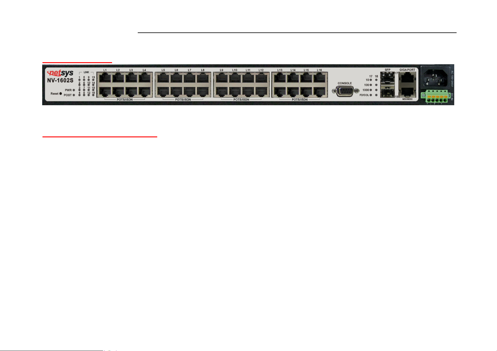
Product Guide
Product Name:2 ports 10/100/1000 Mbps Ethernet plus 16 ports 100 Mbps VDSL2 With SNMP Management IP DSALM
1.4 Features & Specifications
Compliant with ITU-T G993.2 VDSL2, G993.1 VDSL, G997.1, G994.1 G.hs standard
Compliant with IEEE-802.3, 802.3u, 802.3ab, 802.3z Ethernet Standard.
Support 8a, 8b, 8c, 8d, 12a, 12b, 17a and 30a band profiles.
Support 997 and 998 band plans.
Supports Jumbo packet up to 9k byte.
Supports interleave delay for noise resistant and data loss.
Supports Virtual Noise.
Supports SELT(Single-Ended Loop Testing).
Supports Trellis coding for against noise.
Supports Echo cancellation for against noise.
Supports INP(Impulse Noise Protection) for multicarrier communication systems.
Support UPBO(Upstream PBO) and DPBO(Downstream PBO).
Supports high bandwidth up to symmetric 100Mbps within 0.3km (984 feet) for VDSL2 ports.
Supports ADSL LIKE long reach mode up to 2.2 km.
Supports bandwidth management (rate control) from 128k to 100Mbps.
20
Page 22

NV-1602S 16 Ports VDSL2 Managed IP DSLAM with Redundant Power USER’S MANUAL Ver.A2
Supports IEEE 802.1q tagging VLAN with Q-in-Q.
Supports quality of phone wiring detected with SNR(Signal to Noise Ratio) indicators.
Supports TOS IEEE-802.1p with 4 priority queues with DSCP.
Supports HTTPS (SSL) web management.
Supports Multicast IP table/IGMP v2 with 512 groups.
Support IEEE 802.1d STP / IEEE 802.1w RSTP & IEEE-802.1s MSTP.
Support port mirroring (sniffer) and broadcast storm filtering.
Supports port security with MAC address filtering.
Supports remote syslog.
Supports traffic storm control.
Support web based for remote management.
Support SNMP v1/v2/v3 RFC-1493 bridge MIBs, RFC-1643 Ethernet MIB, RFC-1213 MIBII.
Support RMON groups 1(Statistics), 2(Alarm), 3(Event), 9(History).
Support HTTP/TFTP for firmware upgrade.
Support In-Band/Out-of-Band management.
Support L2/L3/4 access control list(ACL).
Support DHCP client and Relay & Option 82.
Supports LLDP(Link Layer Discovery Protocol) protocol.
Supports surge protection and splitter on board.
Internal redundant power adapter Input: AC: 50-60Hz, 100-240V or DC: Dual A+B -48V DC power input (-36V to -75V).
Rack mount size 19"/1U
EMI by FCC/CE Class A
Power Consumption: Max :76 W
21
Page 23

NV-1602S 16 Ports VDSL2 Managed IP DSLAM with Redundant Power USER’S MANUAL Ver.A2
Weight : about 5.3 kg
Notes:
1. Features and specifications in this manual are subject to change without prior notice.
2. (*) Firmware upgradeable for future enhancement.
22
Page 24
NV-1602S 16 Ports VDSL2 Managed IP DSLAM with Redundant Power USER’S MANUAL Ver.A2
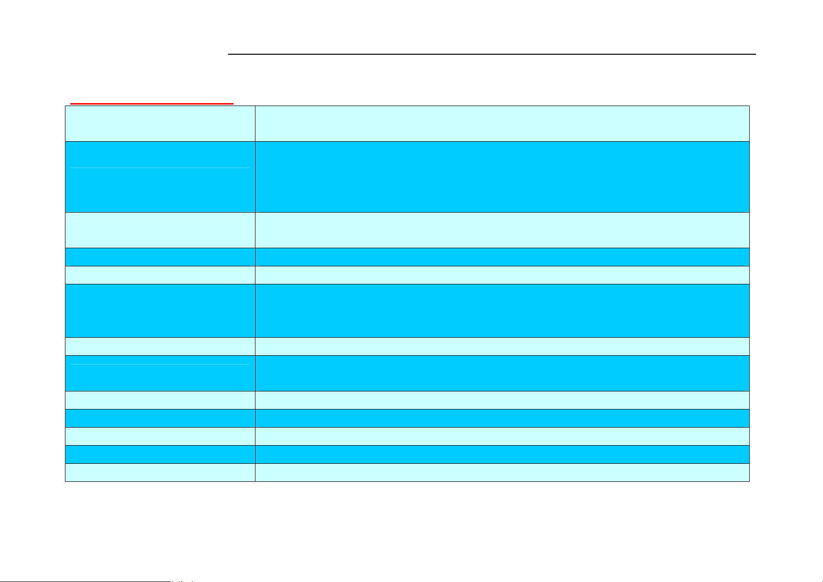
1.5 Product Specification
Standard:
IEEE802.3/802.3u/802.3ab/802.3z standards
ITU-T G993.2, G993.1,G994.1, G997.1 standards
2 * RJ-45 Gigabit TP / SFP combo port
16 * RJ-45 connector for VDSL2 connection
Interface:
16 * RJ-45 connector for POTS/ISDN connection
1 * console port
Full-duplex: IEEE 802.3x
Flow control:
Half-duplex: Back pressure
MAC address table: 8K Entries
VDSL2 Spectrum: 138kHz ~ 30MHz
Power and POST LED
LED indication:
Link/Active/Speed/Duplex/Collision Status for Ethernet ports LED, Show time lock LED for
VDSL2 ports
POTS/ISDN pass filter Spectrum: 0 ~ 120kHz
DC: Dual A+B -48V DC power input (-36V to -75V)
Power Supply
AC: 50/60 Hz, 100~240V AC power input
Operating Temperature: 0°C ~ 50°C (32°F ~ 122°F)
Storage Temperature: -20°C ~ 70°C (-4°F ~ 158°F)
Humidity: 10 to 90% (non-condensing)
Dimensions: 443mm x 393mm x 44mm (17.44" x 15.47" x 1.73")
Chipsets: Lantiq(Infineon)
23
Page 25
NV-1602S 16 Ports VDSL2 Managed IP DSLAM with Redundant Power USER’S MANUAL Ver.A2
Chapter 2.
General Description
2.1 Hardware Description
This section describes the important parts of the IP DSLAM. It features the front and rear panel drawings LEDs, connectors, and
IP DSLAM.
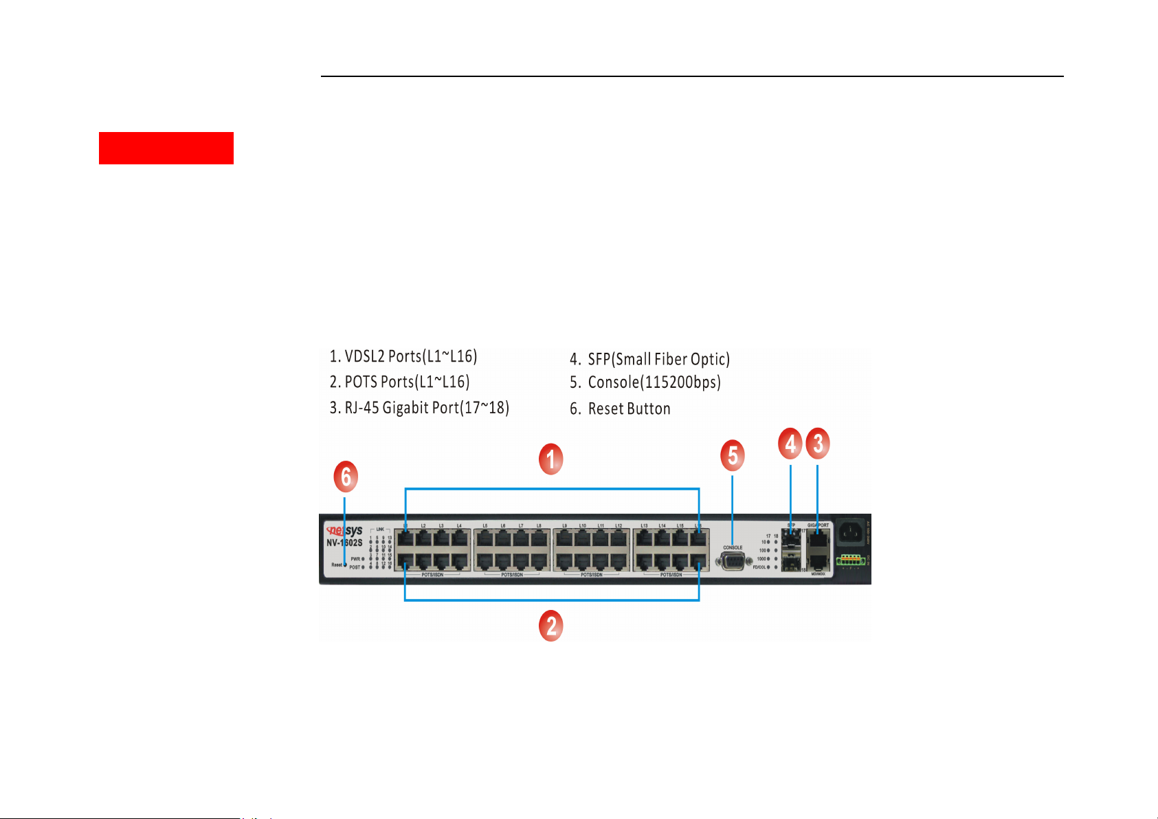
2.2 Front Panel
The following figure shows the front panel.
Figure 2.1 Front Panel description
24
Page 26
NV-1602S 16 Ports VDSL2 Managed IP DSLAM with Redundant Power USER’S MANUAL Ver.A2
Several LED indicators for monitoring the device itself, and the network status. At a quick glance of the front panel, the user
would be knew if the product is receiving power; if it is monitoring another IP DSLAM or other devices; or if a problem exists
on the network.
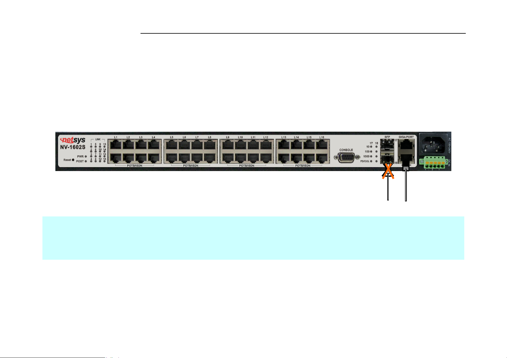
Provides two 1000Mbps auto-sensing RJ-45 Ethernet ports and two GIGA Port.
GIGA Port supports RJ-45 or SFP Interface auto link function. You can use RJ-45 interface or SFP
Interface.Figure 2.2
Note:
NV-1602S supports two gigabit TP/SFP combo interfaces, one is copper interface and the other is small fiber optic interface. 17 and
18 port is RJ45 interface, SFP port is SFP interface. GIGA port supports Hot Swappable function; user can plug or unplug Giga port
when the switch is operating. Please note that do not use the GIGA port RJ-45 interface and SFP interface in the same time,
otherwise it will link in Copper mode (default).
25
Page 27
NV-1602S 16 Ports VDSL2 Managed IP DSLAM with Redundant Power USER’S MANUAL Ver.A2
2.3 SFP Fiber Optics
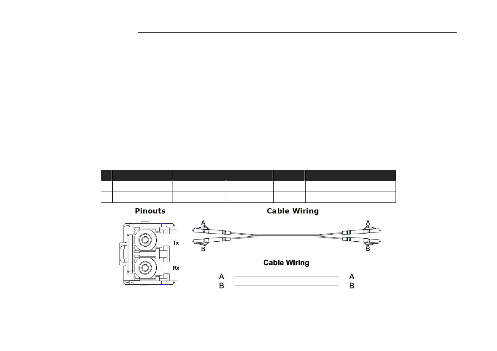
A gigabit interface converter (SFP) is a transceiver that converts electric currents (digital highs and lows) to optical signals, and
optical signals to digital electric currents. The SFP is typically employed in fiber optic and Ethernet systems as an interface for
high-speed networking. The data transfer rate is 1.25 gigabit per second.
SFP modules allow technicians to easily configure and upgrade electro-optical communications networks. The typical SFP
transceiver is a plug-in module that supports hot-plugging (it can be removed and replaced without turning off the system).
The devices are economical, because they eliminate the necessity for replacing entire boards at the system level. Upgrading
can be done with any number of units at a time, from an individual module to all the modules in a system. SFP (Small Form
Pluggable Transceivers), meet the Gigabit Interface Converter specification Rev. 5.4 (MOD_DEF4) industry standard.
Mode Wave length Bit Rate Voltage
Power Margin
1 LX-Single Mode 10km 1.25Gbps 3.3V 10.5db(10KM or above)
2 SX- Multi Mode 550m 1.25Gbps 3.3V 8.5db(550m)
26
Page 28
NV-1602S 16 Ports VDSL2 Managed IP DSLAM with Redundant Power USER’S MANUAL Ver.A2
This LED light is located at the left side on the front panel. It will light up (ON) to show that the
IP
The
2.4 LED Indications
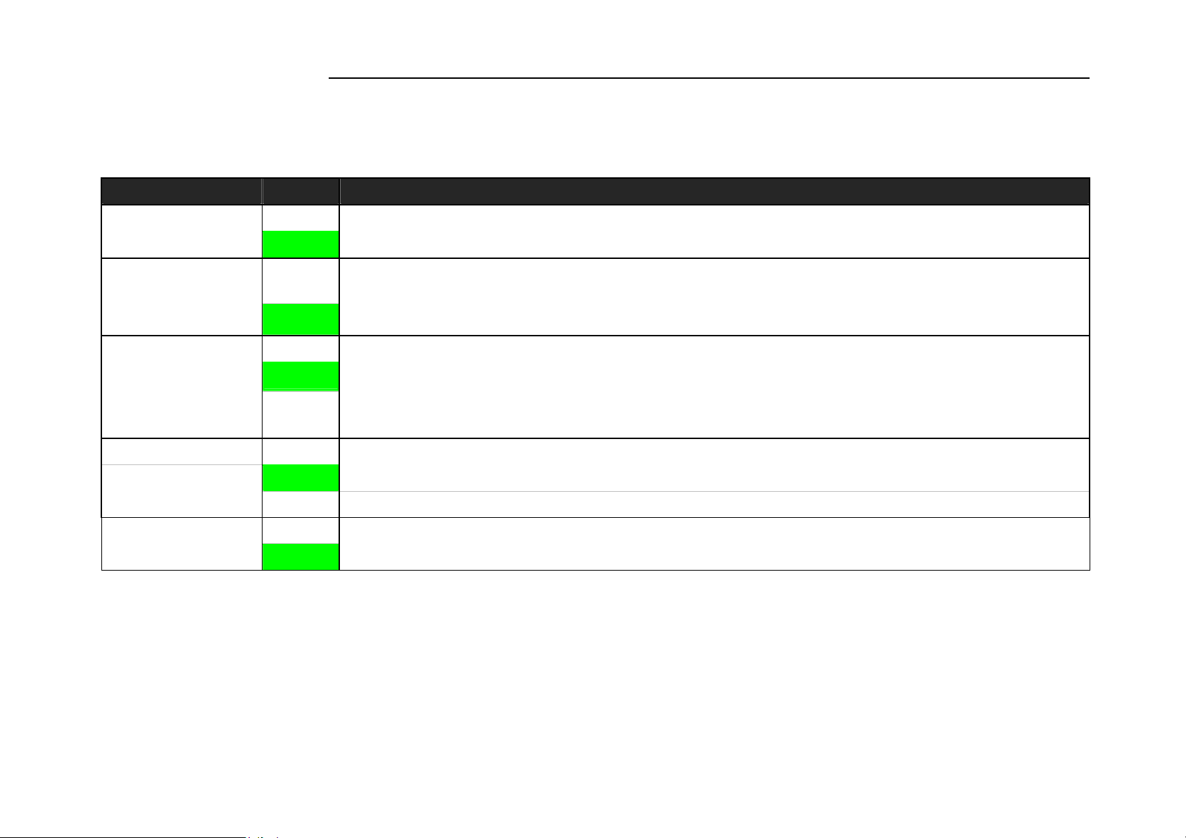
The followings describe the function of each LED indicator:
LEDs Status Descriptions
PWR
(Power LED)
POST
Port 17
Port 18
10/100/1000
FULL/Col
(Full-Duplex LEDs )
(Collision LEDs)
L1~L16
Steady
Green
Steady
Green
Steady
Green
Blinking
Steady
Green
Blinking Blinking to show collision status.
Steady LED light up Steady to show VDSL2 Link is established
Green LED light off Steady to show VDSL2 Link is not established
product is receiving power. Conversely, no light (OFF) means the product is not receiving power.
POST(Power On Self Testing)
POST Led will light to show system is booting now.
When system is ready the LED will light off.
Giga port indicates that communications have been set 10/100/1000 Mbps. Each port on the
DSLAM is assigned an LED light for 100 or 1000 Base-TX connecting
Blinking to show data on Traffic status.
Fiber mode only support.
Indicates that communications have been set to full-duplex operation for the indicated port,
indicator lights up working in Full Duplex, and light down working in Half Duplex
27
Page 29

NV-1602S 16 Ports VDSL2 Managed IP DSLAM with Redundant Power USER’S MANUAL Ver.A2
2.5 Rear Panel
The following figure shows the rear panel of the IP DSLAM.
Figure 2.3 Rear Panel
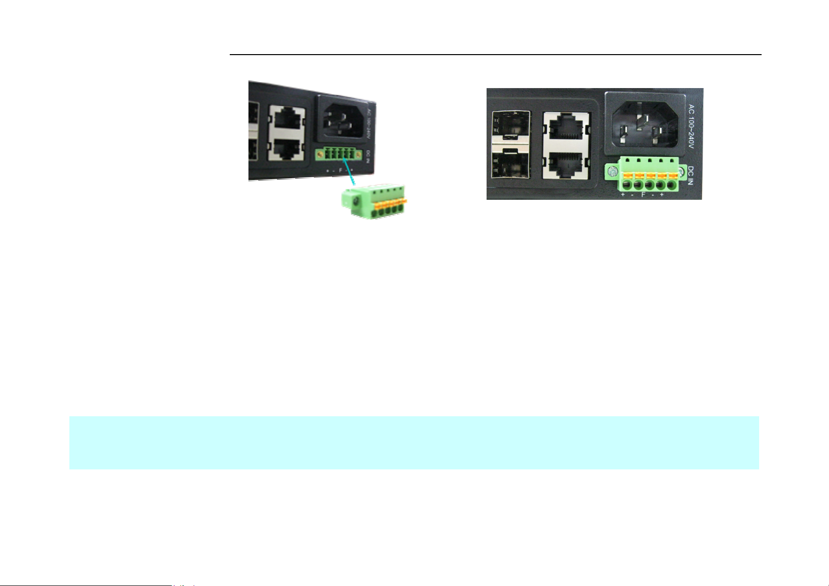
2.6 AC Power Socket
The power cord should be plug into this socket. The AC Socket accepts AC power 100 to 240 voltage.
28
Page 30
NV-1602S 16 Ports VDSL2 Managed IP DSLAM with Redundant Power USER’S MANUAL Ver.A2
2.7 DC Power Socket
The NV-1602S can be powered two -48V DC power supply. The DC power interface is a 5-pin terminal block is located below the AC
socket of the DSLAM. 2P is for accommodating one DC power input and other 2P is for accommodating another DC power input.
The center pin of the terminal block is FGND. The DC power should be connected to a well-fused power supply. When using a DC
voltmeter, Please check for proper voltage: -75V ~ -36 VCD, and make sure that the polarity is correct.
**Redundancy
During operation, both power supplies are switched on and share the current load. In case that one of them should fail, the other
will instantaneously take 100% of the load without any loss. Similarly, if one power supply is removed from servicing, it can be
switched off and removed while the chassis continues functioning.
Note:
It is recommend that the -48VDC be supplied directly and independently by a power feeding system and also avoid having a parallel
or mutual connection with other -48VDC power supplier of telecom equipment. This is to guarantee our products against interference
by other equipment while they are working.
29
Page 31

NV-1602S 16 Ports VDSL2 Managed IP DSLAM with Redundant Power USER’S MANUAL Ver.A2
Chapter 3. Installation
3.1 Hardware Installation
This chapter describes how to install the IP DSLAM and establish network connections. You may install this IP DSLAM on any
level surface (table, shelf, 19 inch rack or wall mounting). However, please take note of the following minimum site requirements
before you begin.
4 plastic feet on the bottom has been pre-installed.
3.2 Pre-Installation Requirements
Before you start actual hardware installation, make sure you can provide the right operating environment, including power
requirements, sufficient physical space, and proximity to other network devices that are to be connected. Verify the following
installation requirement:
Power requirements: AC 100V to 240 V at 50 to 60 Hz.
The IP DSLAM power supply automatically adjusts to the input voltage level.
The IP DSLAM should be located in a cool dry place, with at least 10cm/4in of space at the front and back for well
ventilation.
Place the IP DSLAM out of direct sunlight, and away from heat sources or areas with a high amount of electromagnetic
interference.
Check if network cables and connectors needed for installation are available.
Please note the NV-1602S internal splitter, can pass through voice spectrum is 0KHz ~ 120KHz.
30
Page 32
NV-1602S 16 Ports VDSL2 Managed IP DSLAM with Redundant Power USER’S MANUAL Ver.A2
3.3 General Rules
Before making any connections to the IP DSLAM, note the following rules:
• Ethernet Port (RJ-45)
All network connections to the bridge Ethernet port must be made using Category 5 UTP/STP or above for
100Mbps, Category 3, 4 UTP for 10Mbps.
No more than 100 meters of cabling may be use between the MUX or HUB and an end node.
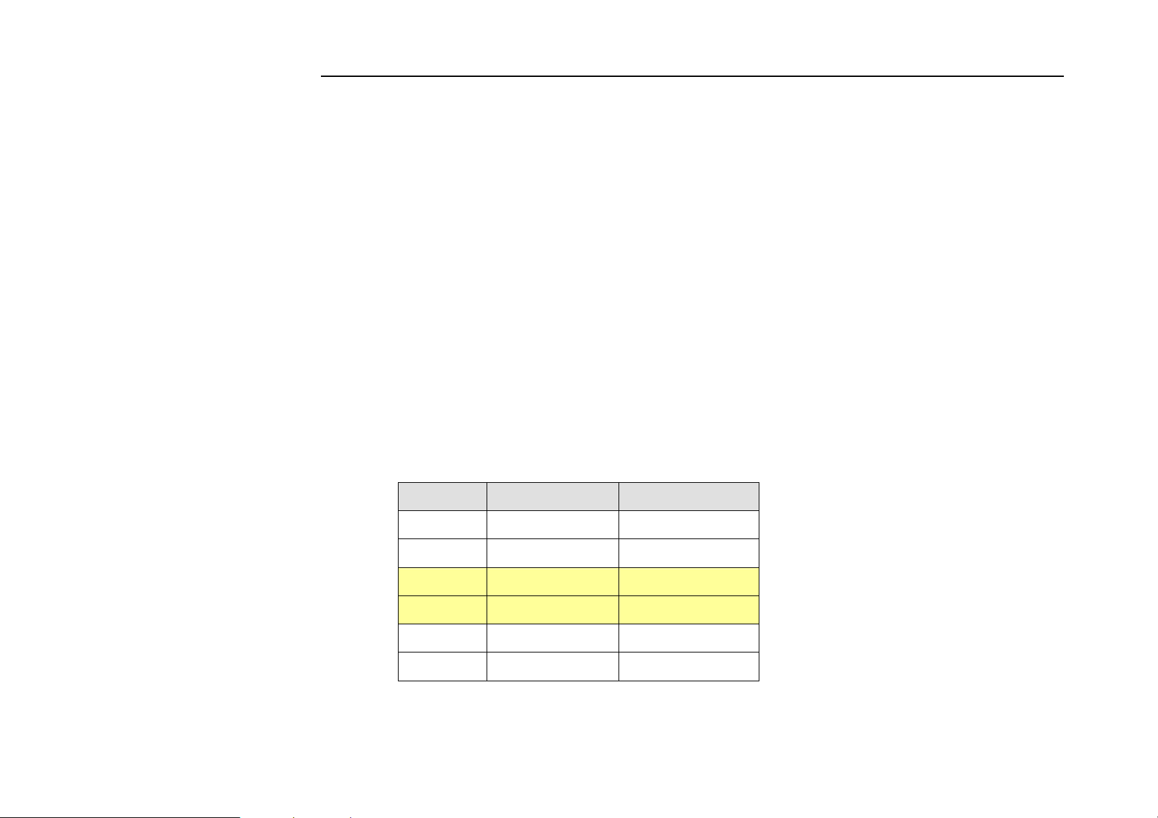
• VDSL2 Port (RJ-11)
All network connections to the RJ-11port must use 24~26 gauge with twisted pair phone wiring.
We do not recommend the use of the telephone line 28 gauge or above.
The RJ-11 connectors have six positions, two of which are wired. The router uses the center two pins. The
pin out assignment for these connectors is presented below.
Please note that the line port is no polarity, therefore user can reverse the two wires of the phone cable
when installed.
RJ-11 Pin out Assignments
Pin# MNEMONIC FUNCTION
1 NC Unused
2 NC Unused
3 DSL Used
4 DSL Used
5 NC Unused
6 NC Unused_
31
Page 33

NV-1602S 16 Ports VDSL2 Managed IP DSLAM with Redundant Power USER’S MANUAL Ver.A2
3.4 Connection Configuration
The IP DSLAM has 16 x 100 Mbps VDSL2 ports. And 2 Giga Ethernet ports which support connection to 10/100/1000 Ethernet.
Support full or half-duplex operation and Auto MDI/MDIX. The transmission mode is using auto-negotiation. Therefore, the
devices attached to these ports must support auto-negotiation unless they will always operate at half duplex. If transmissions
must run at full duplex, but the attached device does not support auto-negotiation, then you should upgrade this device to a
newer version that supports auto-negotiation.
Use any of the 17~18 ports to connect to devices such as a workstation, server, bridge or router. You can also cascade to
another compatible IP DSLAM or hub by connecting an MDI or MDIX port.
1. User can connect an (17~18) station port on the IP DSLAM to any device that uses a standard network interface such as a
optical fiber converter, workstation or server, or also to a network interconnection device such as a bridge or router
(depending on the port type implemented).
2. Prepare the network devices you wish to network. Make sure you have installed VDSL2 CPE Bridge making a connection to
any of the IP DSLAM (L1~L16) station ports. You also need to prepare 24~26 gauge with twisted pair phone wire with RJ11
plugs at both ends.
3.Connect one end of the cable to the RJ-45 port of the network interface card, and the other end to any available (9~10) station
port on the IP DSLAM. Every port support either 10 /100/1000 Mbps connections. When inserting an RJ-45 plug, be sure the
tab on the plug clicks into position to ensure that it is properly seated.
Notes:
1. Be sure each twisted-pair cable (RJ-45) do not exceed by 100 meters (328 feet).
2. We advise using Category 5 cable for Cable Modem or router connections or to attach to any high bandwidth device to avoid
any confusion or inconvenience.
32
Page 34
NV-1602S 16 Ports VDSL2 Managed IP DSLAM with Redundant Power USER’S MANUAL Ver.A2
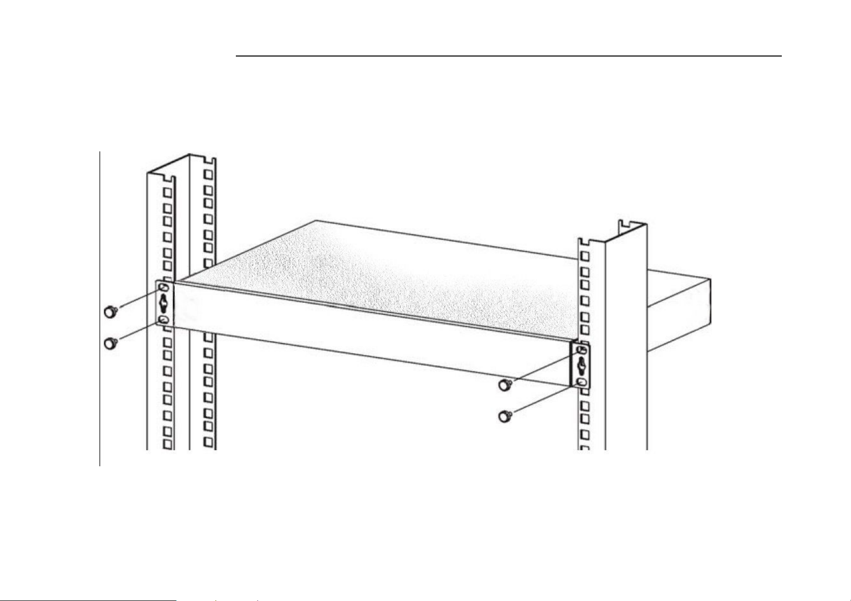
3.5 Mounting the Switch on a Rack
1. Position a mounting bracket on one side of the rack, linging up the two screw holes on the bracket with the screw holes on
the side of the rack.
2. Using a screwdriver, install the M5 flat head screws through the mounting bracket holes into the rack.
3. Repeat steps 1 and 2 to attach the second mounting bracket on the other side of the rack.
33
Page 35
NV-1602S 16 Ports VDSL2 Managed IP DSLAM with Redundant Power USER’S MANUAL Ver.A2
Chapter 4. Management Configuration
4.0 In-Band Management
Console port (RS-232) Configuration
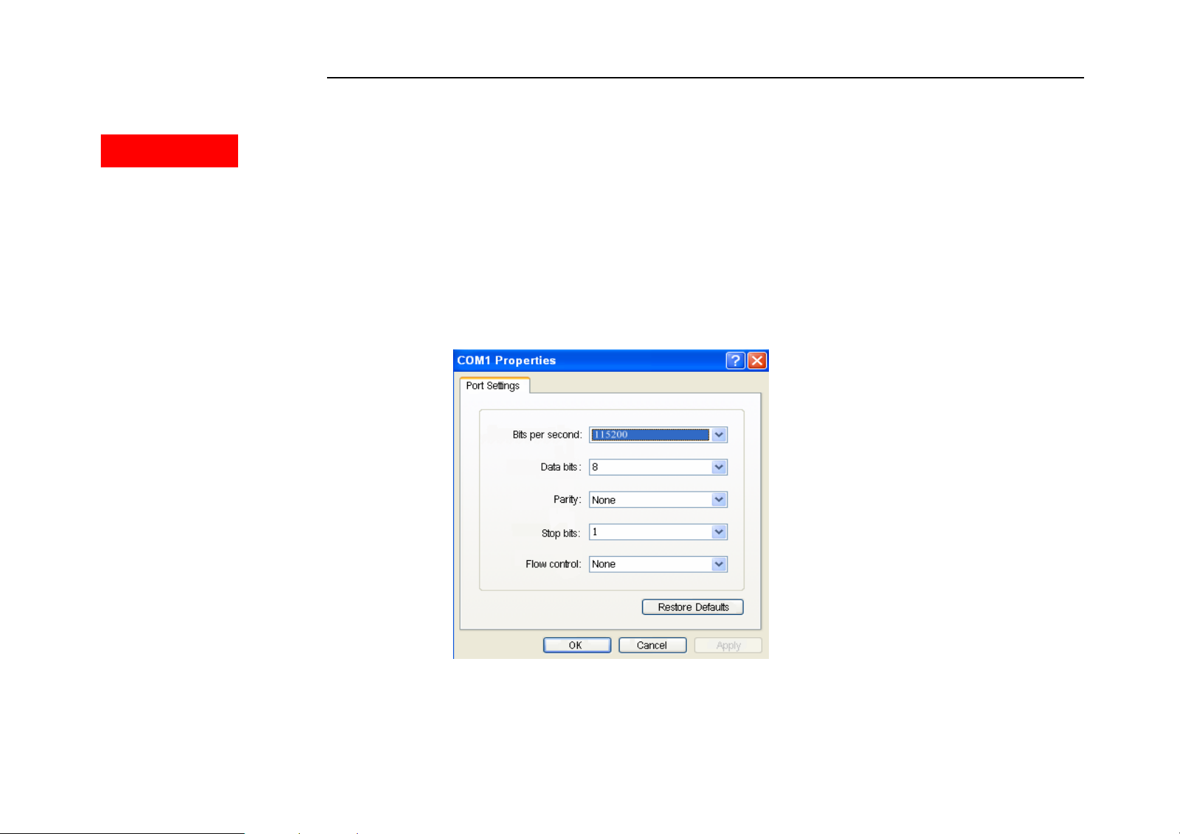
You can configure the product with the local serial console port, If one of the Ethernet port is not in use, you can disable it, that
procedure is to connect a notebook computer to the RS-232 port, then boot operating systems, such as using the Windows
operating system, and run “Hyper-terminal” program into terminal window, and setup step are as follow.
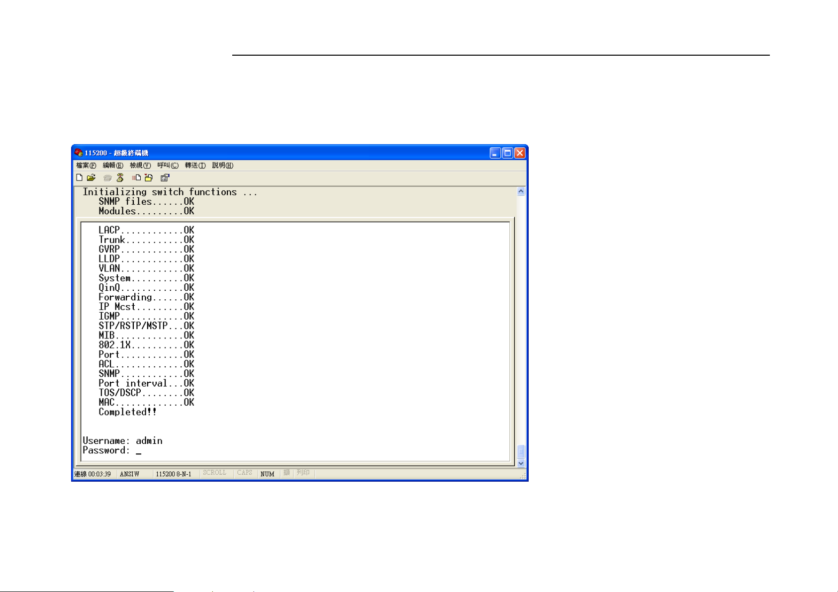
1. Set “Bits per second” at 115200 to the content window.
34
Page 36
NV-1602S 16 Ports VDSL2 Managed IP DSLAM with Redundant Power USER’S MANUAL Ver.A2
2. Set “Flow control” at None
3. Connects PC with the IP DSLAM, you will find login manual window on the screen then enter
Login name :”admin” ; password:”123”
35
Page 37
NV-1602S 16 Ports VDSL2 Managed IP DSLAM with Redundant Power USER’S MANUAL Ver.A2
4. Setting IP Address by Console Port
When you are going to login a IP DSLAM through the web page, you have to configure the IP address first. The default IP address /
netmask / default gateway of a switch is 192.168.16.249 / 255.255.255.0 / 192.168.16.1, without making any configuration
changes in advance, you can login a IP DSLAM with default IP address as long as the default IP address can function properly in
your network environment. Otherwise, you have to re-configure the IP address, subnet mask and default gateway. The following
show how to configure the IP address of a IP DSLAM.
First, login with the console port.
Username: admin
Password: 123
Second, you will now enter the “IP Address ”, then, setup the IP address, subnet mask and gateway.
Switch# configure
Switch(config)# ip address 192.168.1.1 255.255.255.0
Switch(config)# ip default-gateway 192.168.1.254
Notes:
1. As you may identify from the commands above Industrial VDSL2 Router is a Linux based device.
Many of the common Linux commands can be used here. However, please consider that you purchased a VDSL2 device, not a PC.
And always keep in mind that provider gives you support for configuring a standard VDSL2 device. If you try to use the VDSL2
device as a Linux hardware platform and modify its internal software structure, there is no support or warranty on the unit.
2. The command line only support L2 switch function such as VLAN, rate control, STP...etc, it does not support VDSL2 configuration
command line such as VDSL2 channel, Interleave delay. The L2 switch function was wrote in the chapter 4, and the VDSL2 function
was wrote in the chapter 5.
36
Page 38
NV-1602S 16 Ports VDSL2 Managed IP DSLAM with Redundant Power USER’S MANUAL Ver.A2
4.0.1 Operation Notice
To enter the “configuration” mode, you need to be in the privileged mode, and then type the command configure
Switch# configure
Switch (config) #
4.0.1.0
The following generic function keys provide functions in all of the menus:
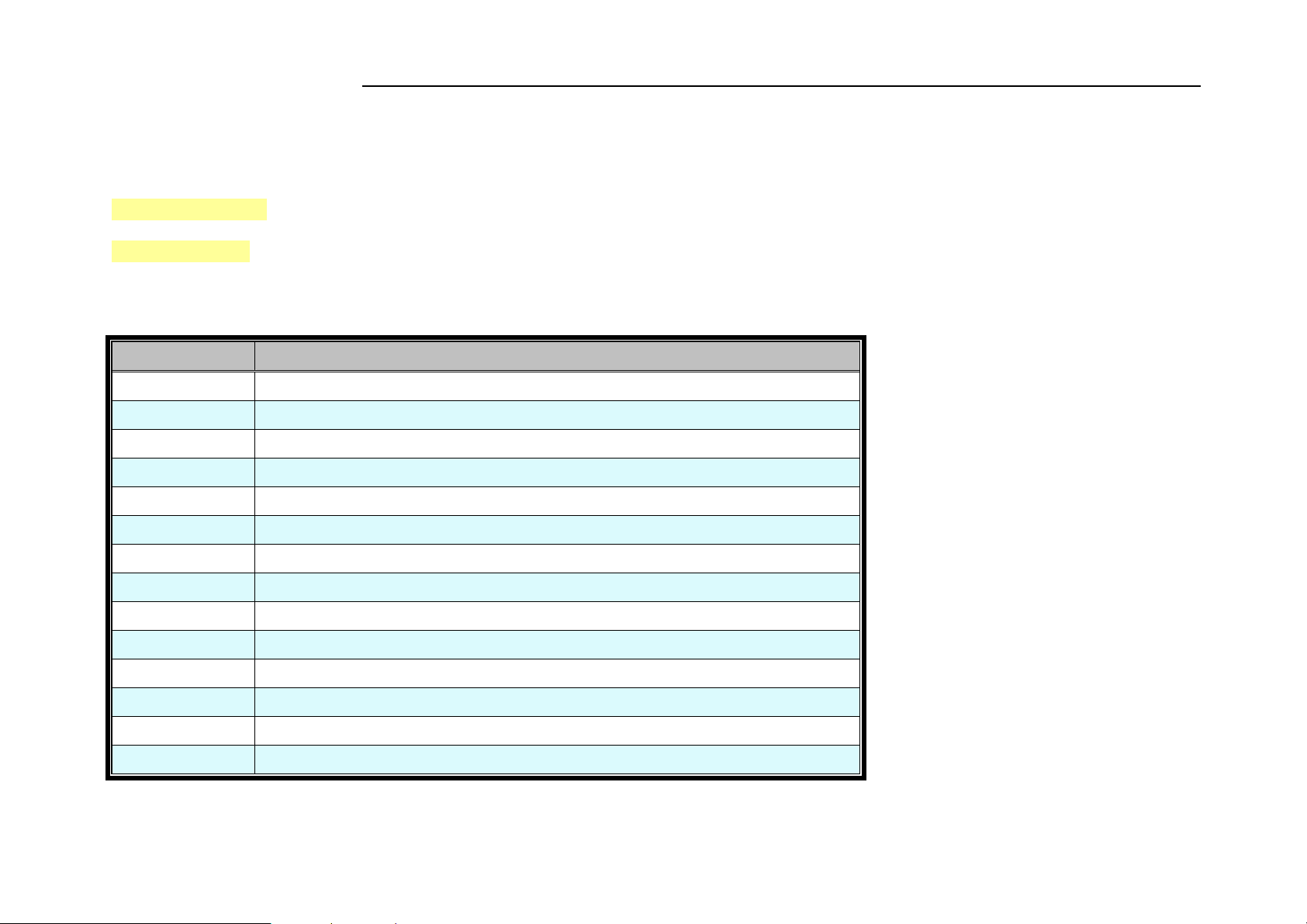
Keys Function
<Ctrl>-B; ←
<Ctrl>-D Deletes the character at the cursor.
<Ctrl>-E Jumps to the end of the current command line.
<Ctrl>-F; →
<Ctrl>-K Deletes from the cursor to the end of the command line.
<Ctrl>-N; ↓
<Ctrl>-P; ↑
<Ctrl>-U Deletes from the cursor to the beginning of the command line.
<Ctrl>-W Deletes the last word typed.
<Esc> B Moves the cursor backward one word.
<Esc> D Deletes from the cursor to the end of the word.
<Esc> F Moves the cursor forward one word.
<Backspace> Delete the character before the cursor.
Command Line Editing
Moves the cursor back one character.
Moves the cursor forward one character.
Enters the next command line in the command history.
Enters the previous command line in the command history.
<Del> Delete the character at the cursor.
37
Page 39

NV-1602S 16 Ports VDSL2 Managed IP DSLAM with Redundant Power USER’S MANUAL Ver.A2
4.0.1.1
You may enter “?” at any command mode, and the CLI will return possible commands at that point, along with some description of
the keywords:
Switch (config) # copy tftp?
running-config Running configurations
flash Flash configurations
firmware Download firmware
You may use the <Tab> key to do keyword auto completion:
Switch (config) # copy tftp r<Tab>
Switch (config) # copy tftp running-config
You do not need to type in the entire commands; you only need to type in enough characters for the CLI to recognize the
command as unique. The following example shows you how to enter the show running-config command:
Switch (config) # sh ru
Command Help
4.0.1.2 Upgrade firmware via console command line
Please run Hyper terminal into terminal window and setup steps are as bellow:
1. Please connects NV-1602's console port to PC or laptop PC series port.
2. Launch "Hyper Terminal" into terminal window on your PC.
38
Page 40

NV-1602S 16 Ports VDSL2 Managed IP DSLAM with Redundant Power USER’S MANUAL Ver.A2
3. Set “Bits per second” at " 115200 " on the content window.
4. Set "Data bits" at " 8 " on the content window.
5. Set "Parity" at " none " on the content window.
6. Set "Stop bits" at " 1 " on the content window.
7. Set “Flow control” at “ none ” on the content window.
8. Power on NV-1602S and wait some time until the login menu appears.
9. Please enter login name ” admin ” ; password ” 123 ” to access configuration menu.
10. You will see a symbol as "Switch#", and ready to management NV-1602S via console.
Note: A TFTP server program is required to be installed in the PC for specified route for following steps.
11. At the CLI command, type the command " conf " and enter to the configuration mode.
12. At the CLI command, type the command "copy tftp firmware <ip-addr> <remote-file>" to upgrade the firmware.
<ip-addr> specifies the IP address of the TFTP server.
<remote-file> specifies the file name to download from the TFTP server.
13. Repeat step 9-11 to enter the configuration mode, and type the command " show info ” to show the firmware version, it means
that the firmware is updated successfully.
4.0.1.3 Reset system to default via console command line
1. At the CLI command, type the command " erase startup-config " to reset system to default.
2. At the CLI command, type the command " boot " to reboot the NV-1602S.
3. Follow the section 4.0.1.2 step 9-11 to enter the configuration mode, and type the command " show ip " to find the default ip
address.
Note: Default ip it shows must be 192.168.16.249.
39
Page 41

NV-1602S 16 Ports VDSL2 Managed IP DSLAM with Redundant Power USER’S MANUAL Ver.A2
4.0.2 System Commands
show running-config
Display the running configuration of the IP DSLAM.
copy running-config startup-config
Backup the switch configurations.
erase startup-config
Reset to default factory settings at next boot time.
clear arp [<ip-addr>] Clear entries in the ARP cache.
Parameters:
[<ip-addr>] specifies the IP address to be cleared. If no IP address is entered, the entire ARP cache is cleared.
show arp
Show the IP ARP translation table.
ping ip-addr [<1..999>] Send ICMP ECHO_REQUEST to network hosts.
Parameters:
[<1..999>] specifies the number of repetitions. If not entered, it will continue to ping until you press <Ctrl>-C to stop.
[no] per-vlan-flooding-portmask Enable or disable per VLAN default flooding portmask.
40
Page 42

NV-1602S 16 Ports VDSL2 Managed IP DSLAM with Redundant Power USER’S MANUAL Ver.A2
per-vlan-flooding-portmask <unicast | multicast> <vlan-id> <port-list> Set unicast or multicast per VLAN default flooding
portmask.
show per-vlan-flooding-portmask
Display unicast and multicast per VLAN default flooding portmask table.
4.0.3 Switch Static Configuration
4.0.3.0 Port Configuration and Status
port state <on | off> [<port-list>]
Turn the port state on or off.
Parameters:
<port-list> specifies the ports to be turn on or off. If not entered, all ports are turn on or off.
port nego <force | auto | nway-force> [<port-list>]
Set port negotiation.
Parameters:
<port-list> specifies the ports to be set.If not entered, all ports are set.
port speed <10 | 100 | 1000> <full | half> [<port-list>]
Set port speed (in mbps) and duplex.
Parameters:
41
Page 43
NV-1602S 16 Ports VDSL2 Managed IP DSLAM with Redundant Power USER’S MANUAL Ver.A2
<port-list> specifies the ports to be set. If not entered, all ports are set.
port flow <enable | disable> <enable | disable> [<port-list>]
Enable or disable port flow control.
Parameters:
1st <enable | disable> enables or disables flow control in full duplex mode.
2nd <enable | disable> enables or disables flow control in half duplex mode.
<port-list> specifies the ports to be set. If not entered, all ports are set.
port rate <ingress | egress> <0..8000> [<port-list>]
Set port effective ingress or egress rate.
Parameters:
<0..8000> specifies the ingress or egress rate.<0..8000>
<port-list> specifies the ports to be set. If not entered, all ports are set.
port security <on | off> [<port-list>]
Set port priority. When port security is on, the port will stop MAC address learning, and forward only packets with MAC address
in the static MAC address table.
Parameters:
<port-list> specifies the ports to be set. If not entered, all ports are set.
port protected group <1-2> <port-list>
Set protected port group member.
42
Page 44

NV-1602S 16 Ports VDSL2 Managed IP DSLAM with Redundant Power USER’S MANUAL Ver.A2
Parameters:
<port-list> specifies the group member ports.
port protected <port-list>
Set protected port list.
Parameters:
<port-list> specifies the protected port list.
port priority <disable | low | high> [<port-list>]
Set port priority.
Parameters:
<port-list> specifies the ports to be set. If not entered, all ports are set.
port jumboframe <enable | disable> [<port-list>]
Set port jumbo frame. When port jumbo frame is enable, the port forward jumbo frame packet
Parameters:
<port-list> specifies the ports to be set. If not entered, all ports are set.
port interval <0-3600>
While flooding CPU port at the speed of 4MB/s or larger, system will close relative port. And system will open this port using this
interval value.0 represents system will never enable this after close it for flooding CPU.
show port status
43
Page 45

NV-1602S 16 Ports VDSL2 Managed IP DSLAM with Redundant Power USER’S MANUAL Ver.A2
Show port status, including port State,Link,VLAN,Negotiation,Speed,Duplex,Flow control, Rate control ,Priority,Security,BSF control.
show port statistics <port-id>
Show port statistics, including TxGoodPkt, TxBadPkt, RxGoodPkt, RxBadPkt,TxAbort, Collision, and DropPkt.
Parameters:
<port-id> specifies the port to be shown.
show port protection
Show protected port information.
4.0.3.1 VLAN
4.0.3.1.0
A Virtual LAN (VLAN) is a logical network group that limits the broadcast domain. It allows you to isolate network traffic so
only members of the VLAN receive traffic from the same VLAN members. Basically, creating a VLAN within a switch is
logically equivalent of reconnecting a group of network devices to another Layer 2 switch. However, all the network devices are
still plugged into the same switch physically. A station can belong to more than one VLAN group. VLAN prevents users from
accessing network resources of another on the same LAN, thus the users can not see the hard disks and printers of another user in
the same building. VLAN can also increase the network performance by reducing the broadcast traffic and enhance the security of
the network by isolating groups.
This Switch supports two types of VLANs:
• Port-based
• IEEE 802.1Q (tag) –based
Virtual LANs
44
Page 46

NV-1602S 16 Ports VDSL2 Managed IP DSLAM with Redundant Power USER’S MANUAL Ver.A2
Notes:
1. The user can select Port-Based VLAN or 802.1q tagging VLAN to use.
2. Example of VLAN setting on “Appendix B”.
Port-based VLANs are VLANs where the packet forwarding decision is made based on the destination MAC address and its
associated port. You must define the outgoing ports allowed for each port when you use port-based VLANs. In port-based VLANs,
the packets received from one port can only be sent to the ports which are configured to the same VLAN. As shown in the
following figure, the switch administrator configured port 1~2 as VLAN 1 and port 3~4 as VLAN 2. The packets received from
port 1 can only be forwarded to port 2. The packets received from port 2 can only be forwarded to port 1. That means the
computer A can send packets to computer B, and vice versa. The same situation also occurred in VLAN 2. The computer C and D
can communicate with each other. However, the computers in VLAN 1 can not see the computers in VLAN 2 since they belonged
to different VLANs.
45
Page 47
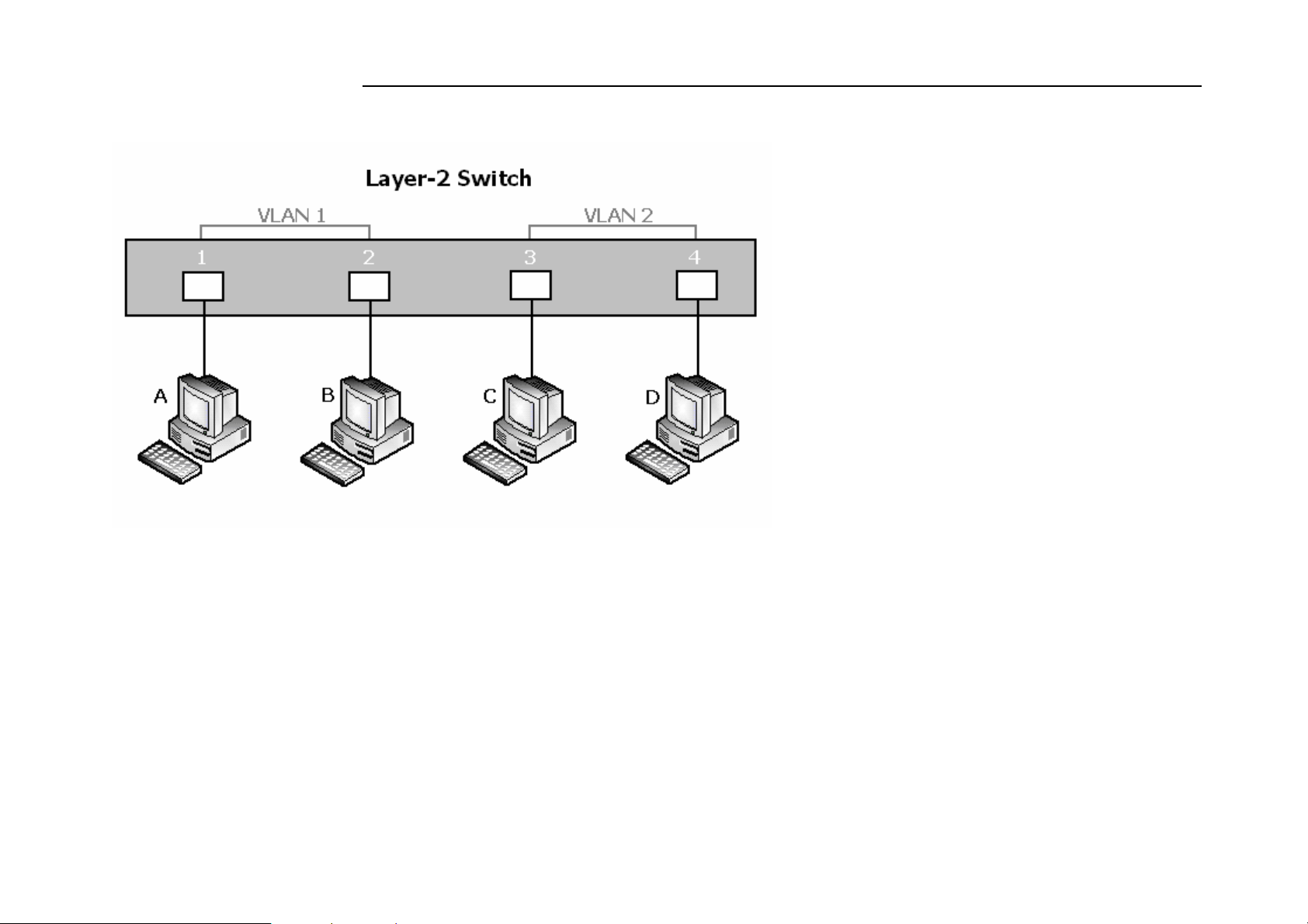
NV-1602S 16 Ports VDSL2 Managed IP DSLAM with Redundant Power USER’S MANUAL Ver.A2
IEEE 802.1Q (tag) -based VLANs enable the Ethernet functionality to propagate tagged packets across the bridges and provides
a uniform way for creating VLAN within a network then span across the network. For egress packet, you can choose to tag it or
not with the associated VLAN ID of this port. For ingress packet, you can forward this packet to a specific port as long as it is also
in the same VLAN group.
The 802.1Q VLAN works by using a tag added to the Ethernet packets. The tag contains a VLAN Identifier (VID) which belongs
to a specific VLAN group. And ports can belong to more than one VLAN.
46
Page 48
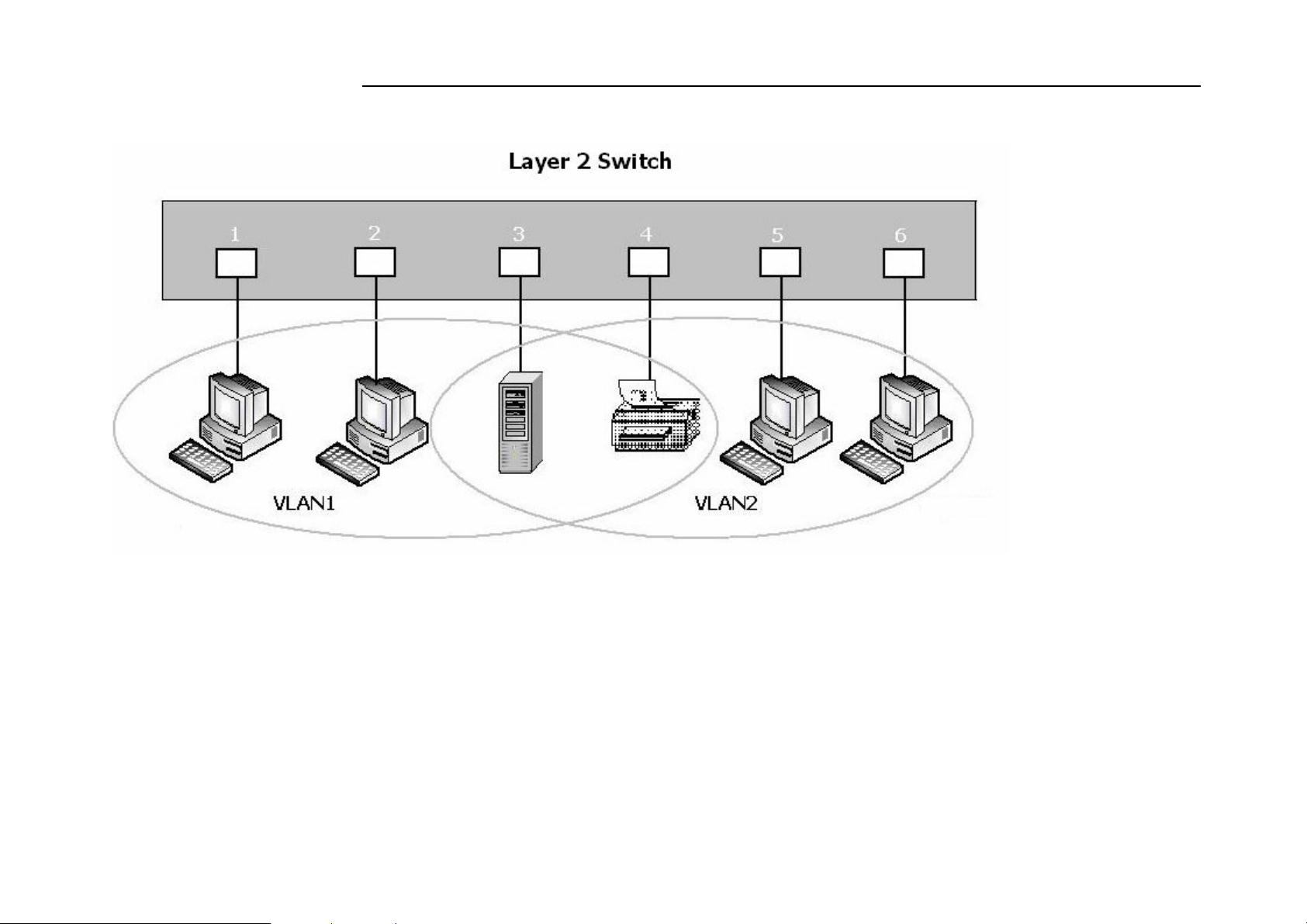
NV-1602S 16 Ports VDSL2 Managed IP DSLAM with Redundant Power USER’S MANUAL Ver.A2
The difference between a port-based VLAN and a tag-based VLAN is that the tag-based VLAN truly divided the network into
several logically connected LANs. Packets rambling around the switches can be forwarded more intelligently. In the figure shown
below, by identifying the tag, broadcast packets coming from computer A in VLAN1 at sw1 can be forwarded directly to VLAN1.
However, the switch could not be so smart in the port-based VLAN mechanism. Broadcast packets will also be forwarded to port
4 of sw2. It means the port-based VLAN can not operate a logical VLAN group among switches.
47
Page 49
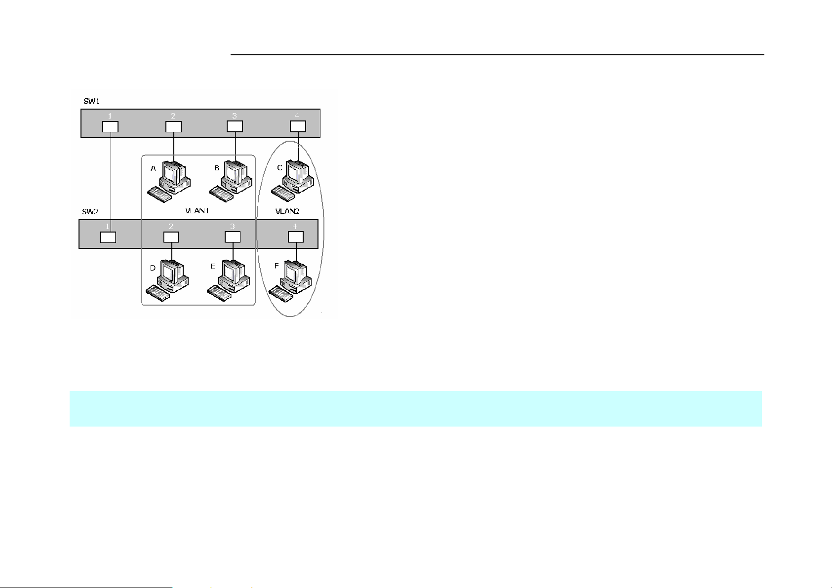
NV-1602S 16 Ports VDSL2 Managed IP DSLAM with Redundant Power USER’S MANUAL Ver.A2
The NV-1602S supports both port-based VLAN and tag-based (802.1Q) VLAN modes. The default configuration is tag-based
(802.1Q) VLAN. In the 802.1Q VLAN, initially, all ports on the switch belong to default VLAN, VID is 1.
Notes:
1. Do not delete the default VLAN group in 802.1Q VLAN mode.
2. dot1q means 802.1Q tagging VLAN.
4.0.3.1.1 VLAN Mode
VLAN Mode: Port based
Packets can go among only members of the same VLAN group. Note all unselected ports are treated as belonging to another single
48
Page 50

NV-1602S 16 Ports VDSL2 Managed IP DSLAM with Redundant Power USER’S MANUAL Ver.A2
VLAN. If the port-based VLAN enabled, the VLAN-tagging is ignored.
show vlan mode
Display the current VLAN mode.
vlan mode (disabled|port-based|dot1q)
Change VLAN mode.
Parameters:
(disabled|port-based|dot1q) specifies the VLAN mode.
Note:
1. Change the VLAN mode for every time, user have to restart the switch for valid value.
2. dot1q means 802.1Q tagging VLAN.
VLAN Mode: 802.1Q
In the setting, port was set to Untagged if devices underneath this port do not support VLAN-tagging. Thus the switch can send
untagged frames to this port. Consequently, device that do not support VLAN-tagging or do not enable VLAN tagging could
successfully fetch the incoming frames and could communicate with device that transfers tagged frames, and vice versa. In the
following figure, two different types of devices want to communicate with each other. Since computer A support 802.1Q VLAN
and computer B do not, you have to configure two ports both beneath the same VLAN group, and set left port to “Tagged”, right
port to “Untagged”. Therefore, two devices will receive packet type as they desired.
49
Page 51
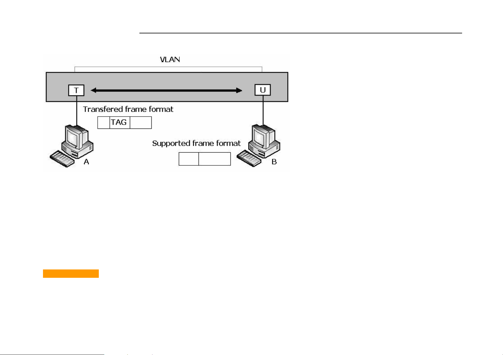
NV-1602S 16 Ports VDSL2 Managed IP DSLAM with Redundant Power USER’S MANUAL Ver.A2
4.0.3.1.2 Advanced 802.1Q VLAN Setting
Ingress filters configuration
When a packet was received on a port, you can govern the switch to drop it or not if it is an untagged packet. Furthermore, if the
received packet is tagged but not belonging to the same VALN group of the receiving port, you can also control the switch to
forward or drop the packet. The example below configures the switch to drop the packets not belonging to the same VLAN group
and forward the packets not containing VLAN tags.
VLAN Commands
show vlan mode
Display the current VLAN mode.
50
Page 52

NV-1602S 16 Ports VDSL2 Managed IP DSLAM with Redundant Power USER’S MANUAL Ver.A2
vlan mode (disabled|port-based|dot1q)
Change VLAN mode.
Parameters:
(disabled|port-based|dot1q) specifies the VLAN mode.
Note:
Change the VLAN mode for every time, user have to restart the switch for valid value.
vlan add <1-4094> <NAME> <cpu-port|no-cpu-port> <LIST> [<LIST>]
Add or edit VLAN entry.
Parameters:
<1-4094> specifies the VLAN id or Group id (if port based VLAN mode)
<NAME> specifies the VLAN group name.
<cpu-port|no-cpu-port> specifies the CPU port belong this VLAN group.
1st <LIST> specifies the ports to be set to VLAN members.
2nd [<LIST>] specifies the ports to be set to tagged members. If not entered, all members set to untagged.
e.g. vlan add 1 vlan1 cpu-port 1-4 . This VLAN entry has four members (from port1 to port4) and all members are untagged.
no vlan <1-4094>
Delete VLAN entry.
Parameters:
<1-4094> specifies the VLAN id or group id (if port based VLAN).
e.g. no vlan 1
51
Page 53
NV-1602S 16 Ports VDSL2 Managed IP DSLAM with Redundant Power USER’S MANUAL Ver.A2
show vlan [<1-4094>]
Show VLAN entry information.
Parameters:
[<1-4094>] specifies the VLAN id, null means all valid entries.
e.g. show vlan 1
show vlan static
Show static VLAN entry information.
vlan pvid <LIST> <1-4094>
Set port default VLAN id.
Parameters:
<LIST> specifies the ports to be set.
<1-4094> specifies the port VLAN id.
show vlan pvid [<LIST>]
Show port default VLAN id.
Parameters:
[<LIST>] specifies the ports to be showed. If not entered, all port’s PVID will be showed.
vlan filter <enable|disable> <enable|disable> <LIST>
Set ingress filter rules.
52
Page 54

NV-1602S 16 Ports VDSL2 Managed IP DSLAM with Redundant Power USER’S MANUAL Ver.A2
Parameters:
1st <enable|disable> specifies the non-members packet will be forwarded or not. If set enable, forward only packets with VID
matching this port's configured VID.
2nd <enable|disable> specifies the untagged frame will be dropped or not. If set enable, drop untagged frame.
<LIST> specifies the port list (eg. 3, 6-8)
show vlan filter [<LIST>]
Show VLAN filter setting.
Parameters:
[<LIST>] specifies the ports to be showed. If not entered, all ports’ filter rules will be showed.
GVRP Commands
[no] gvrp
Enable or disable GVRP.
show gvrp status
Show GVRP enable or disable status.
[no] port gvrp <LIST>
Enable or disable GVRP by port.
Parameters:
<LIST> specifies the port list to be set
53
Page 55

NV-1602S 16 Ports VDSL2 Managed IP DSLAM with Redundant Power USER’S MANUAL Ver.A2
show port gvrp
Show GVRP status by port.
garp timer <join | leave | leave-all> <0..65535>
Set GARP timer.
Parameters:
<join | leave | leave-all> specifies a timer (Join, Leave, or Leave-All) to be set
<0..65535> specifies the timer in seconds.
show garp timer
Show GARP timer.
show gvrp db
Show GVRP DB.
show gvrp gip
Show GVRP GIP.
show gvrp machine
Show GVRP machine.
clear gvrp statistics <LIST>
Clear GVRP statistics by port.
54
Page 56

NV-1602S 16 Ports VDSL2 Managed IP DSLAM with Redundant Power USER’S MANUAL Ver.A2
Parameters:
<LIST> specifies the port list to be set
show gvrp statistics <LIST>
Show GVRP statistics by port.
Parameters:
<LIST> specifies the port list to be set
[no] gvrp debug [<sys | err | pdu | db | gen | garp | gvrp | vlan>]
Enable/disable GVRP debugging output.
4.0.3.1.3 QinQ VLAN Setting
Business customers of service providers often have specific requirements for VLAN IDs and the number of VLANs to be
supported. The VLAN ranges required by different customers in the same service-provider network might overlap, and traffic of
customers through the infrastructure might be mixed. Assigning a unique range of VLAN IDs to each customer would restrict
customer configurations and could easily exceed the VLAN limit (4096) of the IEEE 802.1Q specification. Using the QinQ
feature, service providers can use a single VLAN to support customers who have multiple VLANs. Customer VLAN IDs are
preserved, and traffic from different customers is segregated within the service-provider network, even when they appear to be in
the same VLAN. Using QinQ expands VLAN space by using a VLAN-in-VLAN hierarchy and retagging the tagged packets.
Virtual private networks (VPNs) provide enterprise-scale connectivity on a shared infrastructure, often Ethernet-based, with the
same security, prioritization, reliability, and manageability requirements of private networks. QinQ is a feature designed for
service providers who carry traffic of multiple customers across their networks and are required to maintain the VLAN and Layer
55
Page 57
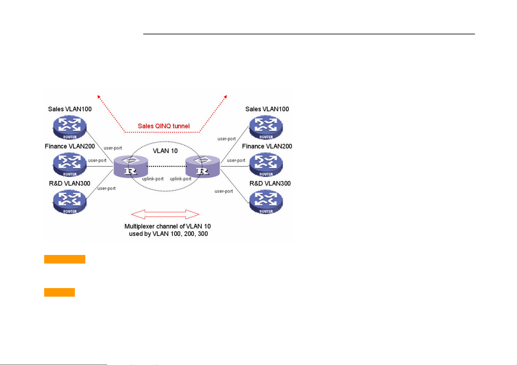
NV-1602S 16 Ports VDSL2 Managed IP DSLAM with Redundant Power USER’S MANUAL Ver.A2
2 protocol configurations of each customer without impacting the traffic of other customers.
The following figure is an example of QinQ VLAN application.
QinQ Commands
qinq enable
Enable QinQ.
[no] qinq
Disable QinQ.
56
Page 58

NV-1602S 16 Ports VDSL2 Managed IP DSLAM with Redundant Power USER’S MANUAL Ver.A2
qinq tpid <TPIDVAL>
Set QinQ tpid.
Parameters:
<TPIDVAL> specifies QinQ tpid value (Hex, 1~FFFF)
qinq userport <enable|disable> <LIST>
A port configured to support client end of QinQ tunnel is called a QinQ user-port. Use this command to enable/disable QinQ
userport to specified port(s).
qinq uplinkport <enable|disable> <LIST>
A port configured to support network end of QinQ tunnel is called a QinQ uplink-port. Use this command to enable/disabel QinQ
uplinkport to specified port(s).
qinq tunnel add <1-25> <1-4094> <LIST>
Add QINQ tunnel.
Parameters:
<1-25> specifies the tunnel ID
<1-4094> specifies the VLAN ID
<LIST> specifies the ports to be set to QINQ tunnel.
qinq tunnel delete <1-25>
Delete QinQ tunnel.
57
Page 59

NV-1602S 16 Ports VDSL2 Managed IP DSLAM with Redundant Power USER’S MANUAL Ver.A2
Parameters:
<1-25> specifies the tunnel ID
show qinq configuration
Show QinQ global and portal configuration
show qinq tunnel
Show QinQ tunnel information
For example, refer to the figure of QinQ application in previous page, a QinQ tunnel using VLAN10 wants to be created for Sales
VLAN100 across the public network. Port1 on left-side VDLS2 IP DSLAM connects to Sales VLAN100 client. Port16 of switch
connects to the public network. The following commands needs to be set:
qinq enable
qinq tpid 8100
qinq userport enable 1
qinq uplinkport enable 16
qinq tunnel add 1 10 1,16
4.0.3.2 Misc Configuration
[no] mac-age-time
Enable or disable MAC address age-out.
mac-age-time <6..1572858> Set MAC address age-out time.
Parameters:
58
Page 60

NV-1602S 16 Ports VDSL2 Managed IP DSLAM with Redundant Power USER’S MANUAL Ver.A2
<6..1572858> specifies the MAC address age-out time. The value must be divisible by 6. Type the number of seconds that an
inactive MAC address remains in the switch’s address table
show mac-age-time
Show MAC address age-out time
broadcast mode <off | 1/2 | 1/4 | 1/8 | 1/12>
Set broadcast storm filter mode to off, 1/2, 1/4, 1/8, 1/12
broadcast select <unicast/multicast | control packet | ip multicast | broadcast>
Select the Broadcast storm filter packet type:
Unicast/Multicast: Flood unicast/multicast filter
Control Packets: Control packets filter
IP multicast: Ip multicast packets filter
Broadcast Packets: Broadcast Packets filter
Collision-Retry <off | 16 | 32 | 48>
Parameters:
<off|16|32|48> In half duplex, collision-retry maximum is 16, 32 or 48 times and packet will be dropped if collisions still happen.
In default (off), if collision happens, it will retry forever.
Hash <crc-hash | direct-map>
Set hash algorithm to CRC-Hash or DirectMap.
59
Page 61

NV-1602S 16 Ports VDSL2 Managed IP DSLAM with Redundant Power USER’S MANUAL Ver.A2
4.0.3.3 Administration
4.0.3.3.0 Change Username/Password
hostname <name-str>
Set switch name.
<name-str> specifies the switch name. If you would like to have spaces within the name, use quotes (“”) around the name.
no hostname
Reset the switch name to factory default setting.
[no] password <manager | operator | all>
Set or remove username and password for manager or operator. The manager username and password is also used by the web UI.
4.0.3.3.1 IP Configuration
User can configure the IP setting and fill in the new value.
ip address <ip-addr> <ip-mask>
Set IP address and subnet mask.
ip default-gateway <ip-addr>
Set the default gateway IP address.
show ip
Show IP address, subnet mask, and the default gateway.
60
Page 62

NV-1602S 16 Ports VDSL2 Managed IP DSLAM with Redundant Power USER’S MANUAL Ver.A2
show info
Show basic information, including system info, MAC address, and firmware version.
dhcp
Set IP DSLAM as dhcp client, it can get ip from dhcp server
Note:
If this command was set, the IP DSLAM will reboot.
show dhcp
show dhcp enable/disable
4.0.3.4 Port Mirroring
Port monitoring is a feature to redirect the traffic occurred on every port to a designated monitoring port on the IP DSLAM . With this
feature, the network administrator can monitor and analyze the traffic on the entire LAN segment. In NV-1602S, you can specify one
port to be the monitoring port and any single port to be the monitored port. You also can specify the direction of the traffic that
you want to monitor. After properly configured, packets with the specified direction from the monitored ports are forwarded to the
monitoring port.
61
Page 63

NV-1602S 16 Ports VDSL2 Managed IP DSLAM with Redundant Power USER’S MANUAL Ver.A2
Note:
1. The Port Monitoring default setting is off.
2. The analysis port is dedicated as mirroring port with duplicated traffic flow from mirrored port. The ordinary network traffic is
not available for the analysis port.
3. Any member port is not available for this function
mirror-port <rx | tx | both> <port-id> <port-list> Set port monitoring information. (RX only|TX only|both RX and TX)
Parameters:
rx specifies monitoring rx only.
tx specifies monitoring tx only.
both specifies monitoring both rx and tx.
<port-id> specifies the analysis port ID. This port receives traffic from all monitored ports.
<port-list> specifies the monitored port list.
show mirror-port
Show port monitoring information
4.0.3.5 Quality of Service
There are four transmission queues with different priorities in NV-1602S: Highest, SecHigh, SecLow and Lowest. The switch will
take packets from the four queues according to its QoS mode setting. If the QoS mode was set to “Disable”, the switch will not
perform QoS on its switched network. If the QoS mode was set to “High Empty Then Low”, the switch will never exhaust packets
from a queue until the queues with higher priorities are empty. If the QoS mode was set to “weight ratio”, the switch will exhaust
62
Page 64

NV-1602S 16 Ports VDSL2 Managed IP DSLAM with Redundant Power USER’S MANUAL Ver.A2
packets from the queues according to the ratio. The default value of QoS mode is “weight 8:4:2:1.” That means the switch will
first exhaust 8 packets from the queue with highest priority, and then exhaust 4 packets from the queue with second high priority,
and so on.
When the switch received a packet, the switch has to decide which queue to put the received packet into. In NV-1602S, the switch
will put received packets into queues according to the settings of “802.1p Priority” and “Static Port Ingress Priority.” When the
received packet is an 802.1p tagged packet, the switch will put the packet into a queue according to the 802.1p Priority setting.
Otherwise, the switch will put the packet into a queue according the setting of Static Port Ingress Priority.
802.1p Priority: the 802.1p packet has a priority tag in its packet header. The range of the priority is 7~0. The NV-1602S can
specify the mapping between 802.1p priority and the four transmission queues. In the default setting, the packets with 802.1p
priority 0~1 are put into the queue with lowest priority, the packets with 802.1p priority 2~3 are put into queue with second low
priority, and so on.
Static Port Ingress Priority: each port is assigned with one priority 7~0. The priority of the packet received from one port is set
to the same priority of the receiving port. When the priority of the received packet was determined, the packet is treated as an
802.1p packet with that priority and will be put into a queue according to the 802.1p Priority setting.
4.0.3.5.0 QoS Configuration
QoS Mode:
First Come First Service: The sequence of packets sent is depending on arrive orders.
All High before Low: The high priority packets sent before low priority packets.
WRR: Weighted Round Robin. Select the preference given to packets in the switch's high-priority queue. These options
represent the number of higher priority packets sent before one lower priority packet is sent.
63
Page 65
NV-1602S 16 Ports VDSL2 Managed IP DSLAM with Redundant Power USER’S MANUAL Ver.A2
For example, 8 Highest:4 second-high means that the switch sends 8 highest-priority packets before sending 4 second high
priority packets.
Qos Level: 0~7 priority level can map to highest, second-high, second-low, lowest queue.
Commands:
qos priority <first-come-first-service | all-high-before-low |weighted-round-robin> [<highest-weight>][<sechighweight>][<
sec low -weight>] [<lowest-weight>]
Set 802.1p priority.
e.g. qos priority weighted-round-robin 8,4,2,1
qos level < highest | second-high | second-low | lowest > <level-list>
Set priority levels to highest, second-high, second-low and lowest.
Parameters:
<level-list> specifies the priority levels to be high or low. Level must be
between 1 and 7.
e.g. qos level highest 7
e.g. qos level lowest 4
show qos
Show QoS configurations, including 802.1p priority, priority level.
e.g. show qos
QoS configurations:
64
Page 66
NV-1602S 16 Ports VDSL2 Managed IP DSLAM with Redundant Power USER’S MANUAL Ver.A2
QoS mode: first come first service
Highest weight: 8
Second High weight: 4
Second Low weight: 2
Lowest weight: 1
802.1p priority[0-7]:
Lowest Lowest SecLow SecLow SecHigh SecHigh Highest Highest
4.0.3.5.1 Per Port Priority
port priority <disable | [0-7]> [<port-list>]
Set port priority.
Parameters:
[<port-list>] specifies the ports to be set. If not entered, all ports ar
e.g. port priority disable 1-5
4.0.3.6 MAC Address Table
clear mac-address-table
Clear all dynamic MAC address table entries.
mac-address-table static <mac-addr> <vlan-id> <port-id | port-list>
Set static unicast or multicast MAC address. If multicast MAC address
(address beginning with 01:00:5E) is supplied, the last parameter must be port-list.
Otherwise, it must be port-id.
65
Page 67

NV-1602S 16 Ports VDSL2 Managed IP DSLAM with Redundant Power USER’S MANUAL Ver.A2
no mac-address-table static <mac-addr> <vlan-id>
Delete static unicast or multicast MAC address table entries.
show mac-address-table
Display MAC address table entries.
show mac-address table static
Display static MAC address table entries.
show mac-address-table multicast
Display multicast related MAC address table.
smac-address-table static <mac-addr> <vlan-id> <port-id | port-list>
Set static unicast or multicast MAC address in secondary MAC address table. If multicast MAC address
(address beginning with 01:00:5E) is supplied, the last parameter must be port-list.
Otherwise, it must be port-id.
show smac-address-table
Display secondary MAC address table entries.
show smac-address-table multicast
Display multicast related secondary MAC address table.
66
Page 68

NV-1602S 16 Ports VDSL2 Managed IP DSLAM with Redundant Power USER’S MANUAL Ver.A2
[no] filter <mac-addr> <vlan-id>
Set MAC address filter. The packets will be filtered if both of the destination
MAC address and the VLAN tag matches the filter entry. If the packet does not have
a VLAN tag, then it matches an entry with VLAN ID 1.
show filter
Display filter MAC address table.
4.0.3.7 MAC Limit
MAC limit allows users to set a maximum number of MAC addresses to be stored in the MAC address table. The MAC addresses
chosen to be stored in MAC address table is the result of first-come-first-save policy. Once a MAC address is stored in the MAC
address table, it stays in until it is aged out. When an “opening” is available, the switch stored the first new MAC address it sees in
that opening. All packets from MAC addresses not in the MAC address table should be blocked.
User can configure the MAC limit setting and fill in the new value.
mac-limit
Enable MAC limit.
no mac-limit
Disable MAC limit.
Mac-limit <port-list> <1-64>
67
Page 69

NV-1602S 16 Ports VDSL2 Managed IP DSLAM with Redundant Power USER’S MANUAL Ver.A2
Set port MAC limit value, 0 to turn off MAC limit of port.
show mac-limit
Show MAC limit information, including MAC limit enable/disable, per-port MAC limit setting.
68
Page 70

NV-1602S 16 Ports VDSL2 Managed IP DSLAM with Redundant Power USER’S MANUAL Ver.A2
4.0.4 Protocol Related Configuration
4.0.4.0 STP/RSTP
[no] spanning-tree
Enable or disable spanning-tree.
spanning-tree forward-delay <4-30>
Set spanning tree forward delay used, in seconds.
Parameters:
<4-30> specifies the forward delay, in seconds. Default value is 15.
Note: The parameters must enforce the following relationships:
2*(hello-time + 1) <= maximum-age <= 2*(forward-delay - 1)
spanning-tree hello-time <1-10>
Set spanning tree hello time, in seconds.
Parameters:
<1-10> specifies the hello time, in seconds. Default value is 2.
Note: The parameters must enforce the following relationships:
2*(hello-time + 1) <= maximum-age <= 2*(forward-delay - 1)
spanning-tree maximum-age <6-40>
Set spanning tree maximum age, in seconds.
Parameters:
<6-40> specifies the maximum age, in seconds. Default value is 20.
69
Page 71

NV-1602S 16 Ports VDSL2 Managed IP DSLAM with Redundant Power USER’S MANUAL Ver.A2
Note: The parameters must enforce the following relationships:
2*(hello-time + 1) <= maximum-age <= 2*(forward-delay - 1)
spanning-tree priority <0-61440>
Set spanning tree bridge priority.
Parameters:
<0-61440> specifies the bridge priority. The value must be in steps of 4096.
spanning-tree port path-cost <1-200000000> [<port-list>]
Set spanning tree port path cost.
Parameters:
<1-200000000> specifies port path cost.
[<port-list>] specifies the ports to be set. Null means all ports.
spanning-tree port priority <0-240> [<port-list>]
Set spanning tree port priority.
Parameters:
<0-240> specifies the port priority. The value must be in steps of 16.
[<port-list>] specifies the ports to be set. Null means all ports.
show spanning-tree
Show spanning-tree information.
70
Page 72
NV-1602S 16 Ports VDSL2 Managed IP DSLAM with Redundant Power USER’S MANUAL Ver.A2
show spanning-tree port [<port-list>]
Show spanning tree per port information.
Parameters:
[<port-list>] specifies the port to be shown. Null means all ports.
The remaining commands in this section are only for system with RSTP (rapid
spanning tree, 802.1w) capability:
[no] spanning-tree debug
Enable or disable spanning tree debugging information.
spanning-tree protocol-version <stp | rstp>
Change spanning tree protocol version.
Parameters:
stp specifies the original spanning tree protocol (STP,802.1d).
rstp specifies rapid spanning tree protocol (RSTP,802.1w).
[no] spanning-tree port mcheck [<port-list>]
Force the port to transmit RST BPDUs. No format means not force the port to transmit RST BPDUs.
Parameters:
[<port-list>] specifies the ports to be set. Null means all ports.
[no] spanning-tree port edge-port [<port-list>]
Set the port to be edge connection. No format means set the port to be non-edge connection.
71
Page 73

NV-1602S 16 Ports VDSL2 Managed IP DSLAM with Redundant Power USER’S MANUAL Ver.A2
Parameters:
[<port-list>] specifies the ports to be set. Null means all ports.
[no] spanning-tree port non-stp [<port-list>]
Disable or enable spanning tree protocol on this port.
Parameters:
[<port-list>] specifies the ports to be set. Null means all ports.
spanning-tree port point-to-point-mac <auto | true | false> [<port-list>]
Set the port to be point to point connection.
Parameters:
auto specifies point to point link auto connection.
true specifies point to point link true.
false specifies point to point link false.
[<port-list>] specifies the ports to be set. Null means all ports
.
72
Page 74

NV-1602S 16 Ports VDSL2 Managed IP DSLAM with Redundant Power USER’S MANUAL Ver.A2
4.0.4.1 MSTP
[no] spanning-tree
Enable or disable multiple spanning tree.
[no] spanning-tree debug
Enable or disable multiple spanning tree debugging information.
spanning-tree forward-delay <4-30>
Set spanning tree forward delay of CIST, in seconds.
Parameters:
<4-30> specifies the forward delay, in seconds. Default value is 15.
Note: The parameters must enforce the following relationships:
2*(hello-time + 1) <= maximum-age <= 2*(forward-delay - 1)
spanning-tree hello-time <1-10>
Set spanning tree hello time of CIST, in seconds.
Parameters:
<1-10> specifies the hello time, in seconds. Default value is 2.
Note: The parameters must enforce the following relationships:
2*(hello-time + 1) <= maximum-age <= 2*(forward-delay - 1)
73
Page 75
NV-1602S 16 Ports VDSL2 Managed IP DSLAM with Redundant Power USER’S MANUAL Ver.A2
spanning-tree maximum-age <6-40>
Set spanning tree maximum age of CIST, in seconds.
Parameters:
<6-40> specifies the maximum age, in seconds. Default value is 20.
Note: The parameters must enforce the following relationships:
2*(hello-time + 1) <= maximum-age <= 2*(forward-delay - 1)
spanning-tree priority <0-61440>
Set spanning tree bridge priority of CIST and all MSTIs.
Parameters:
<0-61440> specifies the bridge priority. The value must be in steps of 4096. Default value is 32768.
spanning-tree protocol-version { stp | mstp }
Set spanning tree protocol version of CIST.
Parameters:
stp specifies the original spanning tree protocol (STP,802.1d).
mstp specifies the multiple spanning tree protocol (MSTP,802.1s).
spanning-tree max-hops <1-40>
Set spanning tree bridge maximum hops of CIST and all MSTIs.
Parameters:
<1-40> specifies the bridge maximum hops. Default value is 20.
74
Page 76
NV-1602S 16 Ports VDSL2 Managed IP DSLAM with Redundant Power USER’S MANUAL Ver.A2
spanning-tree name [<name-string>]
Set spanning tree bridge name of CIST.
Parameters:
[<name-string>] specifies the bridge name. Default name is null.
spanning-tree revision <1-65535>
Set spanning tree bridge revision of CIST.
Parameters:
<1-65535> specifies the bridge revision. Default value is 0.
spanning-tree port path-cost <1-200000000> [<port-list>]
Set spanning tree port path cost of CIST.
Parameters:
<1-200000000> specifies port path cost.
[<port-list>] specifies the ports to be set. Null means all ports.
spanning-tree port priority <0-240> [<port-list>]
Set spanning tree port priority of CIST.
Parameters:
<0-240> specifies the port priority. The value must be in steps of 16.
[<port-list>] specifies the ports to be set. Null means all ports.
75
Page 77
NV-1602S 16 Ports VDSL2 Managed IP DSLAM with Redundant Power USER’S MANUAL Ver.A2
[no] spanning-tree port mcheck [<port-list>]
Force the port of CIST to transmit MST BPDUs. No format means not force the port of CIST to transmit MST BPDUs.
Parameters:
[<port-list>] specifies the ports to be set. Null means all ports.
[no] spanning-tree port edge-port [<port-list>]
Set the port of CIST to be edge connection. No format means set the port of CIST to be non-edge connection.
Parameters:
[<port-list>] specifies the ports to be set. Null means all ports.
[no] spanning-tree port non-stp [<port-list>]
Disable or enable spanning tree protocol on the CIST port.
Parameters:
[<port-list>] specifies the ports to be set. Null means all ports.
spanning-tree port point-to-point-mac <auto | true | false> [<port-list>]
Set the port of CIST to be point to point connection.
Parameters:
auto specifies point to point link auto connection.
true specifies point to point link true.
false specifies point to point link false.
[<port-list>] specifies the ports to be set. Null means all ports.
76
Page 78

NV-1602S 16 Ports VDSL2 Managed IP DSLAM with Redundant Power USER’S MANUAL Ver.A2
spanning-tree mst <0-15> priority <0-61440>
Set spanning tree bridge priority of MSTI.
Parameters:
<0-15> specifies the MSTI instance ID.
<0-61440> specifies the MSTI bridge priority. The value must be in steps of 4096. Default value is 32768.
spanning-tree mst <0-15> vlan [<vlan-list>]
Set MSTI to map VLAN list.
Parameters:
<0-15> specifies the MSTI instance ID.
[<vlan-list>] specifies the mapped VLAN list. Null means all VLANs.
spanning-tree mst <0-15> port path-cost <1-200000000> [<port-list>]
Set spanning tree port path cost of MSTI.
Parameters:
<1-200000000> specifies port path cost.
[<port-list>] specifies the ports to be set. Null means all ports.
spanning-tree mst <0-15> port priority <0-240> [<port-list>]
Set spanning tree port priority of MSTI.
Parameters:
<0-240> specifies the port priority. The value must be in steps of 16.
[<port-list>] specifies the ports to be set. Null means all ports.
77
Page 79
NV-1602S 16 Ports VDSL2 Managed IP DSLAM with Redundant Power USER’S MANUAL Ver.A2
no spanning-tree mst <0-15>
Delete the specific MSTI.
Parameters:
<0-15> specifies the MSTI instance ID.
show spanning-tree
Show spanning-tree information of CIST.
show spanning-tree port [<port-list>]
Show spanning tree port information of CIST.
Parameters:
[<port-list>] specifies the port to be shown. Null means all ports.
show spanning-tree mst configuration
Show MST instance map.
show spanning-tree mst <0-15>
Show MST instance information.
Parameters:
<0-15> specifies the MSTI instance ID.
show spanning-tree mst <0-15> port <1-26>
Show specific port information of MST instance.
78
Page 80

NV-1602S 16 Ports VDSL2 Managed IP DSLAM with Redundant Power USER’S MANUAL Ver.A2
Parameters:
<0-15> specifies the MSTI instance ID.
<1-26> specifies port number.
show vlan spanning-tree
Show per VLAN per port spanning tree status.
79
Page 81
NV-1602S 16 Ports VDSL2 Managed IP DSLAM with Redundant Power USER’S MANUAL Ver.A2
4.0.4.2 SNMP
Any Network Management running the simple Network Management Protocol (SNMP) can be management the IP DSLAM .
4.0.4.2.0 System Options
Snmp /no snmp
Enable or disable SNMP.
Show snmp status
Show enable or disable status of SNMP.
snmp system-name <name-str>
Set agent system name string.
Parameters:
<name-str> specifies the system name string.
e.g. snmp system-name SWITCH
snmp system-location <location-str>
Set agent location string.
Parameters:
<location-str> specifies the location string.
e.g. snmp system-location office
snmp system-contact <contact-str>
Set agent system contact string.
Parameters:
<contact-str> specifies the contact string.
e.g. snmp system-contact [email protected]
80
Page 82
NV-1602S 16 Ports VDSL2 Managed IP DSLAM with Redundant Power USER’S MANUAL Ver.A2
show snmp system
Show SNMP system information.
4.0.4.2.1 Community Strings
snmp community <read-sysinfo-only | read-all-only | read-write-all> <community-str>
Set SNMP community string.
Parameters:
<community-str> specifies the community string.
e.g. snmp community read-all-only public
no snmp community <community-str>
Delete SNMP community string.
Parameters:
<community-str> specifies the community string.
e.g. no snmp community public
show snmp community
Show SNMP community strings.
4.0.4.2.2 Trap Managers
snmp trap <ip-addr> [<community-str>] [<1..65535>]
Set SNMP trap receiver IP address, community string, and port number.
Parameters:
81
Page 83
NV-1602S 16 Ports VDSL2 Managed IP DSLAM with Redundant Power USER’S MANUAL Ver.A2
<ip-addr> specifies the IP address.
<community-str> specifies the community string.
<1..65535> specifies the trap receiver port number.
e.g. snmp trap 192.168.200.1 public
no snmp trap <ip-addr> [<1..65535>]
Remove trap receiver IP address and port number.
Parameters:
<ip-addr> specifies the IP address.
<1..65535> specifies the trap receiver port number.
e.g. no snmp trap 192.168.200.1
show snmp trap
Show all trap receivers.
4.0.4.2.3 SNMP V3 VACM (optional)
snmp group <group-name> <v1 | v2c | usm> <security-name>
Join a group.
Parameters:
<group-name> specifies the group name.
<v1 | v2c | usm> specifies the security model.
<security-name> specifies the security name.
e.g. snmp group test usm testuser
82
Page 84
NV-1602S 16 Ports VDSL2 Managed IP DSLAM with Redundant Power USER’S MANUAL Ver.A2
no snmp group <v1 | v2c | usm> <security-name>
Leave a group.
Parameters:
<v1 | v2c | usm> specifies the security model.
<security-name> specifies the security name.
e.g. no snmp group usm testuser
show snmp group
Show group list.
snmp view <view-name> <included | excluded> <view-subtree> <view-mask>
Add a view.
Parameters:
<view-name> specifies the view name.
<included | excluded> specifies the view type.
<view-subtree> specifies the view subtree (e.g. .1.3.6.1.2.1).
<view-mask> specifies the view mask, in hexadecimal digits.
e.g. snmp view testview included 1.3.6.1.2.1 0xff
no snmp view <view-name>
Delete a view.
Parameters:
<view-name> specifies the view name.
83
Page 85
NV-1602S 16 Ports VDSL2 Managed IP DSLAM with Redundant Power USER’S MANUAL Ver.A2
e.g. no snmp view system
show snmp view
Show view list.
snmp access <group-name> <v1 | v2c | usm> <noauth | auth | authpriv> <read-name> <write-name> <notify-name>
Add an access control.
Parameters:
<group-name> specifies the group name.
<v1 | v2c | usm> specifies the security model.
<noauth | auth | authpriv> specifies the security level.
<read-name> specifies the access read view name.
<write-name> specifies the access write view name.
<notify-name> specifies the access notify view name.
e.g. snmp access test usm testauth all all all
no snmp access <group-name> <v1 | v2c | usm> <noauth | auth | authpriv>
Delete an access control.
Parameters:
<group-name> specifies the group name.
<v1 | v2c | usm> specifies the security model.
<noauth | auth | authpriv> specifies the security level.
e.g. no snmp access test usm auth
84
Page 86
NV-1602S 16 Ports VDSL2 Managed IP DSLAM with Redundant Power USER’S MANUAL Ver.A2
show snmp access
Show access list.
4.0.4.2.4 SNMP V3 USM (optional)
snmp engine-id <enterprise-id> <engine-id>
Setup SNMPv3 engine ID.
Parameters:
<engine-id> specifies the engine ID, in the format of text string.
e.g. snmp engine-id 123456789123456789123456
show snmp engine-id
Show SNMPv3 engine ID.
snmp usm-user <user-name> [<md5 | none>]
Add SNMPv3 USM user.
Parameters:
<user-name> specifies the user name.
<md5 | none> specifies the authentication type.
e.g. Create a user name is testuser and password is 12345678, use auth md5 then enter CLI command:
snmp usm-user testuser md5 <cr>
New password for authentication (8<=length<=32):
12345678<cr>
Retype new password:
85
Page 87
NV-1602S 16 Ports VDSL2 Managed IP DSLAM with Redundant Power USER’S MANUAL Ver.A2
12345678<cr>
no snmp usm-user <user-name>
Delete SNMPv3 USM user.
Parameters:
<user-name> specifies the user name.
e.g. no snmp usm-user testuser
show snmp usm-user
Show all SNMPv3 USM users.
86
Page 88
NV-1602S 16 Ports VDSL2 Managed IP DSLAM with Redundant Power USER’S MANUAL Ver.A2
4.0.4.3 IGMP
The Internet Group Management Protocol (IGMP) is an internal protocol of the Internet Protocol (IP) suite.
[no] igmp Enable/disable IGMP snooping.
[no] igmp fastleave Enable/disable IGMP snooping fast leave. If enable, switch will fast delete member who send leave report,
else wait one second.
[no] igmp querier Enable/disable IGMP snooping querier.
[no] igmp CrossVLAN Enable/disable IGMP snooping CrossVLAN
[no] igmp debug Enable/disable IGMP snooping debugging output.
show igmp <status | router | groups | table>
Show IGMP snooping information.
Parameters:
status specifies IGMP snooping status and statistics information.
router specifies IGMP snooping router’s IP address.
groups specifies IGMP snooping multicast group list.
table specifies IGMP snooping IP multicast table entries.
igmp clear_statistics
87
Page 89

NV-1602S 16 Ports VDSL2 Managed IP DSLAM with Redundant Power USER’S MANUAL Ver.A2
Clear IGMP snooping statistics counters.
4.0.4.4 802.1x
This IP DSLAM supports IEEE 802.1x standard which provides port-based access control by validating end user’s authorization
through authentication (RADIUS) server. EAP- MD5/TLS/PEAP authentication types are supported for this IP DSLAM .
[no] dot1x
Enable or disable 802.1x.
radius-server host <ip-addr> <1024..65535> <1024..65535>
Set radius server IP, port number, and accounting port number.
Parameters:
<ip-addr> specifies server’s IP address.
1st <1024..65535> specifies the server port number.
2nd <1024..65535> specifies the accounting port number.
radius-server key <key-str>
Set 802.1x shared key.
Parameters:
<key-str> specifies shared key string.
radius-server nas <id-str>
Set 802.1x NAS identifier.
88
Page 90

NV-1602S 16 Ports VDSL2 Managed IP DSLAM with Redundant Power USER’S MANUAL Ver.A2
Parameters:
<id-str> specifies NAS identifier string.
show radius-server
Show radius server information, including radius server IP, port number, accounting port number, shared key, NAS identifier,
dot1x timeout quiet-period <0..65535>
Set 802.1x quiet period. (default: 60 seconds).
Parameters:
<0..65535> specifies the quiet period, in seconds.
dot1x timeout tx-period <0..65535>
Set 802.1x Tx period. (default: 15 seconds).
Parameters:
<0..65535> specifies the Tx period, in seconds.
dot1x timeout supplicant <1..300>
Set 802.1x supplicant timeout (default: 30 seconds)
Parameters:
<1..300> specifies the supplicant timeout, in seconds.
dot1x timeout radius-server <1..300>
Set radius server timeout (default: 30 seconds).
89
Page 91

NV-1602S 16 Ports VDSL2 Managed IP DSLAM with Redundant Power USER’S MANUAL Ver.A2
Parameters:
<1..300> specifies the radius server timeout, in seconds.
dot1x max-req <1..10>
Set 802.1x maximum request retries (default: 2 times).
Parameters:
<1..10> specifies the maximum request retries.
dot1x timeout re-authperiod <30..65535>
Set 802.1x re-auth period (default: 3600 seconds).
Parameters:
<30..65535> specifies the re-auth period, in seconds.
show dot1x
Show 802.1x information, quiet period, Tx period, supplicant timeout, server timeout, maximum requests, and re-auth period.
dot1x port <fu | fa | au | no> <port-list>
Set 802.1x per port information.
Parameters:
fu specifies forced unauthorized.
fa specifies forced authorized.
au specifies authorization.
no specifies disable authorization.
90
Page 92

NV-1602S 16 Ports VDSL2 Managed IP DSLAM with Redundant Power USER’S MANUAL Ver.A2
<port-list> specifies the ports to be set.
show dot1x port
Show 802.1x per port information.
4.0.4.5 DHCP Relay & Option 82
DHCP is widely used in LAN environments to dynamically assign host IP addresses from a centralized server, which significantly
reduces the overhead of administration of IP addresses. DHCP also helps conserve the limited IP address space because IP
addresses no longer need to be permanently assigned to hosts.
When the DHCP Option 82 feature is enabled on the switch, a subscriber device is identified by the switch port through which it
connects to the network (in addition to its MAC address). Multiple hosts on the subscriber LAN can be connected to the same port
on the access switch and are uniquely identified. Option82 Information is inserted by the switch enabled option-82 feature when
forwarding client-originated DHCP packets to a DHCP server (RFC 3046). Servers may use this information to implement IP
address or other parameter assignment policies. This will significantly enhance the security of DHCP and effectively prevent the
attack of DHCP flood.
91
Page 93
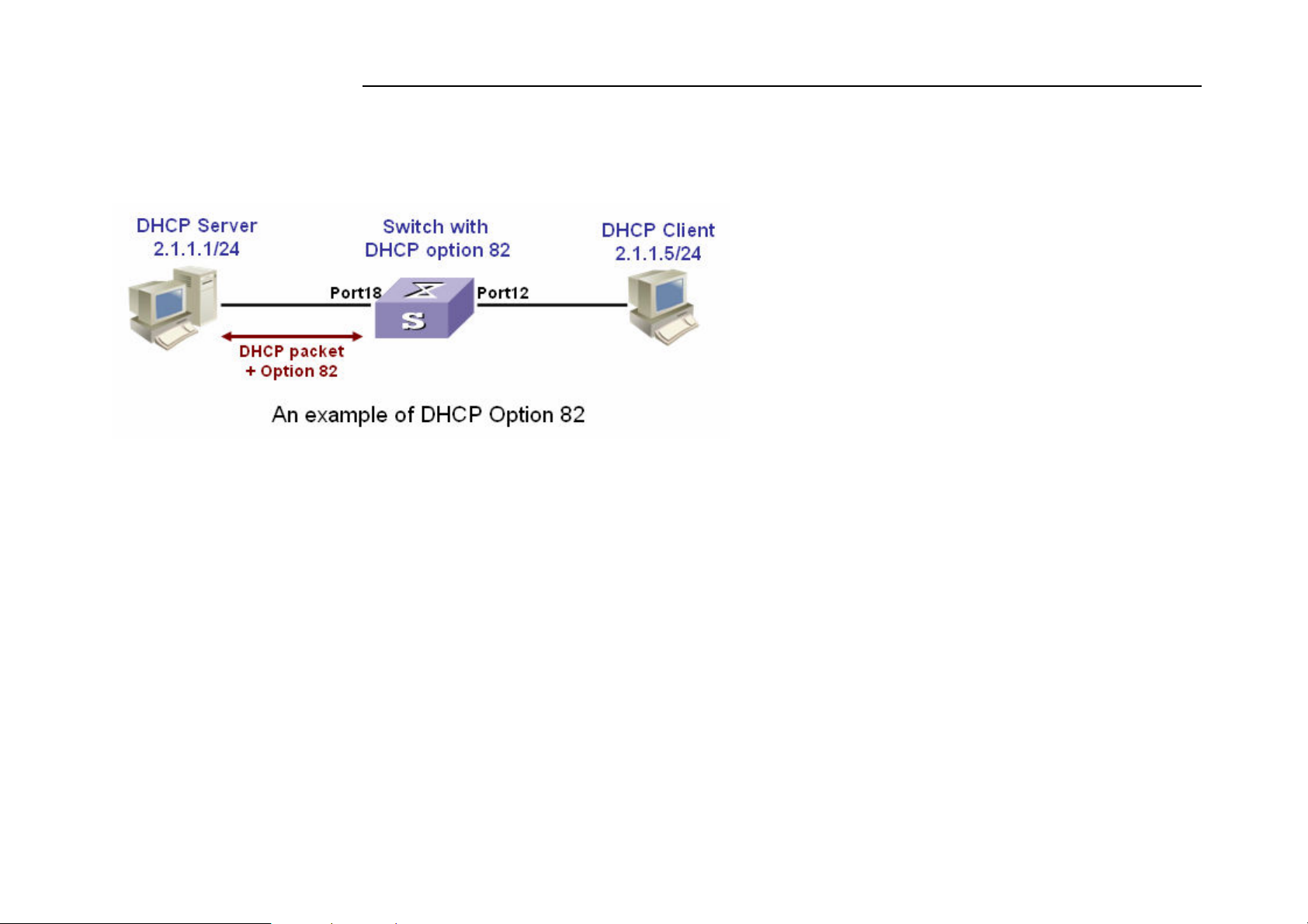
NV-1602S 16 Ports VDSL2 Managed IP DSLAM with Redundant Power USER’S MANUAL Ver.A2
The following figure is an example of DHCP Option 82:
If the DHCP relay feature is enabled on the switch, it forwards requests and replies between clients and servers when they are not
on the same physical subnet. Relay agent forwarding is different from the normal Layer 2 forwarding, in which IP datagrams are
switched transparently between networks. Relay agents receive DHCP messages and generate new DHCP messages to send on
output interfaces. So DHCP server can provide IP addresses to clients spanning multiple subnets instead of deploying a DHCP
server on every subnet.
92
Page 94
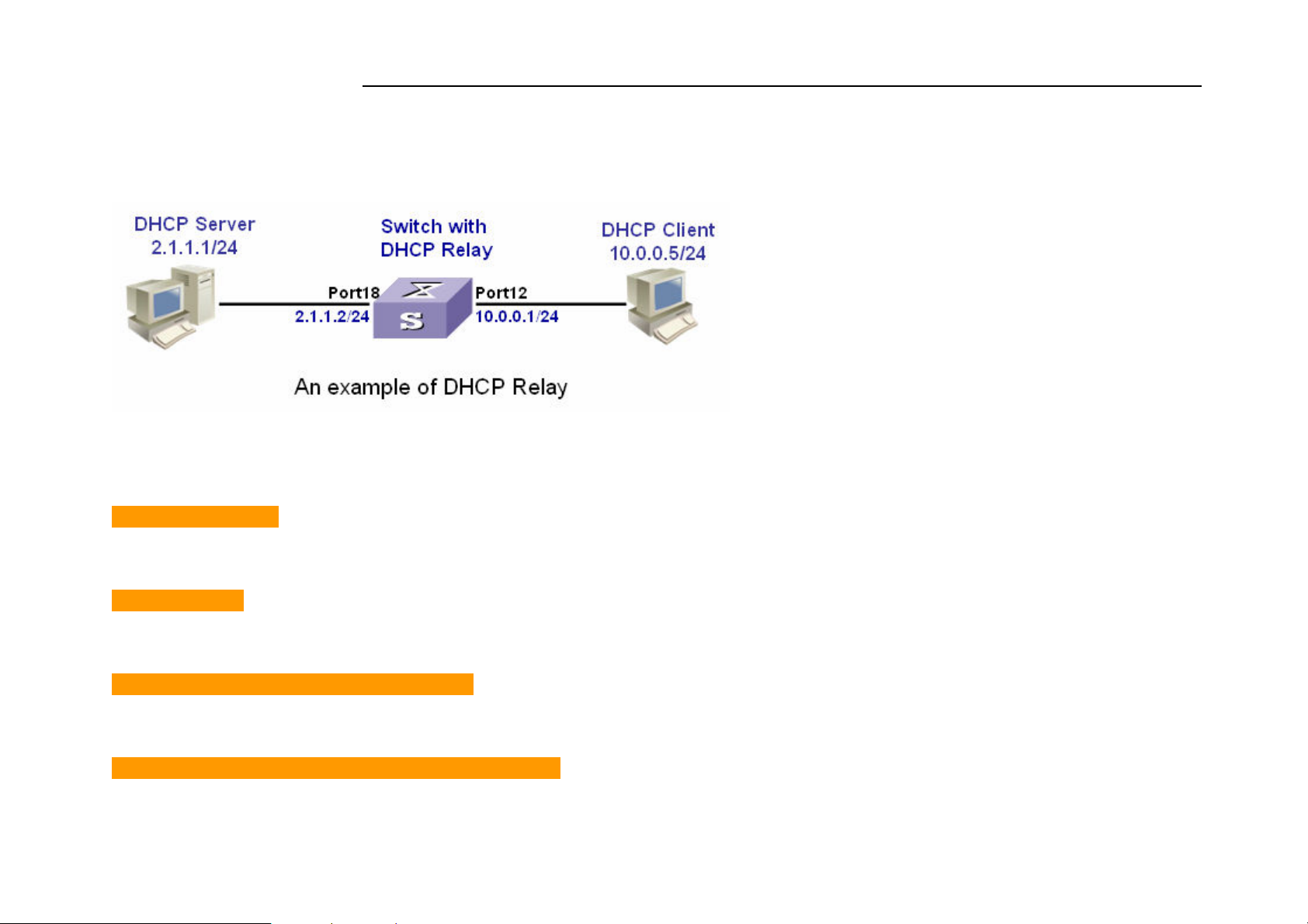
NV-1602S 16 Ports VDSL2 Managed IP DSLAM with Redundant Power USER’S MANUAL Ver.A2
The following figure is an example of DHCP relay:
The following commands are provided for DHCP option82 / relay configuration:
[no] dhcp-option82
Enable/disable DHCP option82 function.
[no] dhcp-relay
Enable/disable DHCP relay function.
dhcp-option82 <enable | disable> <LIST>
Enable/disable port-based option82 function.
dhcp-relay <enable | disable> <LIST> <IP address>
93
Page 95
NV-1602S 16 Ports VDSL2 Managed IP DSLAM with Redundant Power USER’S MANUAL Ver.A2
Enable/disable port-based DHCP relay function.
dhcp router <LIST>
Set DHCP router port
show dhcp configuration
Show DHCP configuration information
For example, refer to the figure of DHCP option 82 in the previous page, use the following commands to achieve:
dhcp-option82
dhcp router 18
dhcp-option82 enable 12
Refer to the example figure of DHCP relay application, use the following commands to achieve:
dhcp-relay
dhcp router 18
dhcp-relay enable 10.0.0.1 12
94
Page 96
NV-1602S 16 Ports VDSL2 Managed IP DSLAM with Redundant Power USER’S MANUAL Ver.A2
4.0.4.6 LLDP
Link Layer Discovery Protocol (LLDP) operates on data link layer. It stores and maintains the information about the local device
and the devices directly connected to it for network administrators to manage networks through NMS (network management
systems). In LLDP, device information is encapsulated in LLDP PDUs in the form of TLV (meaning type, length, and value)
triplets and is exchanged between directly connected devices. Information in LLDP PDUs received is restored in its MIB.
Note:
Currently the LLDP neighbor(s) can be seen through the console only. SNMP browser will be supported in the future.
LLDP Operation Mode
LLDP can operate in one of the following modes.
LLDP Mode Description
TxRx mode A port in this mode sends and receives LLDP PDUs
Tx mode A port in this mode only sends LLDP PDUs
Rx mode A port in this mode only receives LLDP PDUs
Disable mode A port in this mode does not send or receive LLDP PDUs
LLDP is initialized when an LLDP-enabled port changes to operate in another LLDP operating mode. To prevent LLDP from
being initialized too frequently, LLDP undergoes a period before being initialized on an LLDP-enabled port when the port
changes to operate in another LLDP operating mode. The period is known as initialization delay, which is determined by the
re-initialization delay timer.
95
Page 97

NV-1602S 16 Ports VDSL2 Managed IP DSLAM with Redundant Power USER’S MANUAL Ver.A2
Sending LLDP PDUs
A LLDP-enabled device operating in the TxRx mode or Tx mode sends LLDP PDUs to its directly connected devices periodically.
It also sends LLDP PDUs when the local configuration changes to inform the neighboring devices of the change timely. In any of
the two cases, an interval exists between two successive operations of sending LLDP PDUs. This prevents the network from being
overwhelmed by LLDP PDUs even if the LLDP operating mode changes frequently.
To enable the neighboring devices to be informed of the existence of a device or an LLDP operating mode change (from the
disable mode to TxRx mode, or from the Rx mode to Tx mode) timely, a device can invoke the fast sending mechanism. In this
case, the interval to send LLDP PDUs changes to one second. After the device sends specific number of LLDP PDUs, the interval
restores to the normal. (A neighbor is discovered when a device receives an LLDPDU and no information about the sender is
locally available.)
Receiving LLDP PDUs
An LLDP-enabled device operating in the TxRx mode or Rx mode validates the TLVs carried in the LLDP PDUs which receive
and store the valid neighboring information. An LLDP PDU also carries a TTL (time to live) setting with it. The information about
a neighboring device maintained locally ages out when the corresponding TTL expires.
The TTL of the information about a neighboring device is determined by the following expression:
TTL = LLDP hold time × LLDP PDU sending interval (hello-time)
You can set the TTL by configuring the LLDP hold-time and hello-time. Note that the TTL can be up to 65535 seconds. TTL
longer than it will be rounded off to 65535 seconds.
96
Page 98
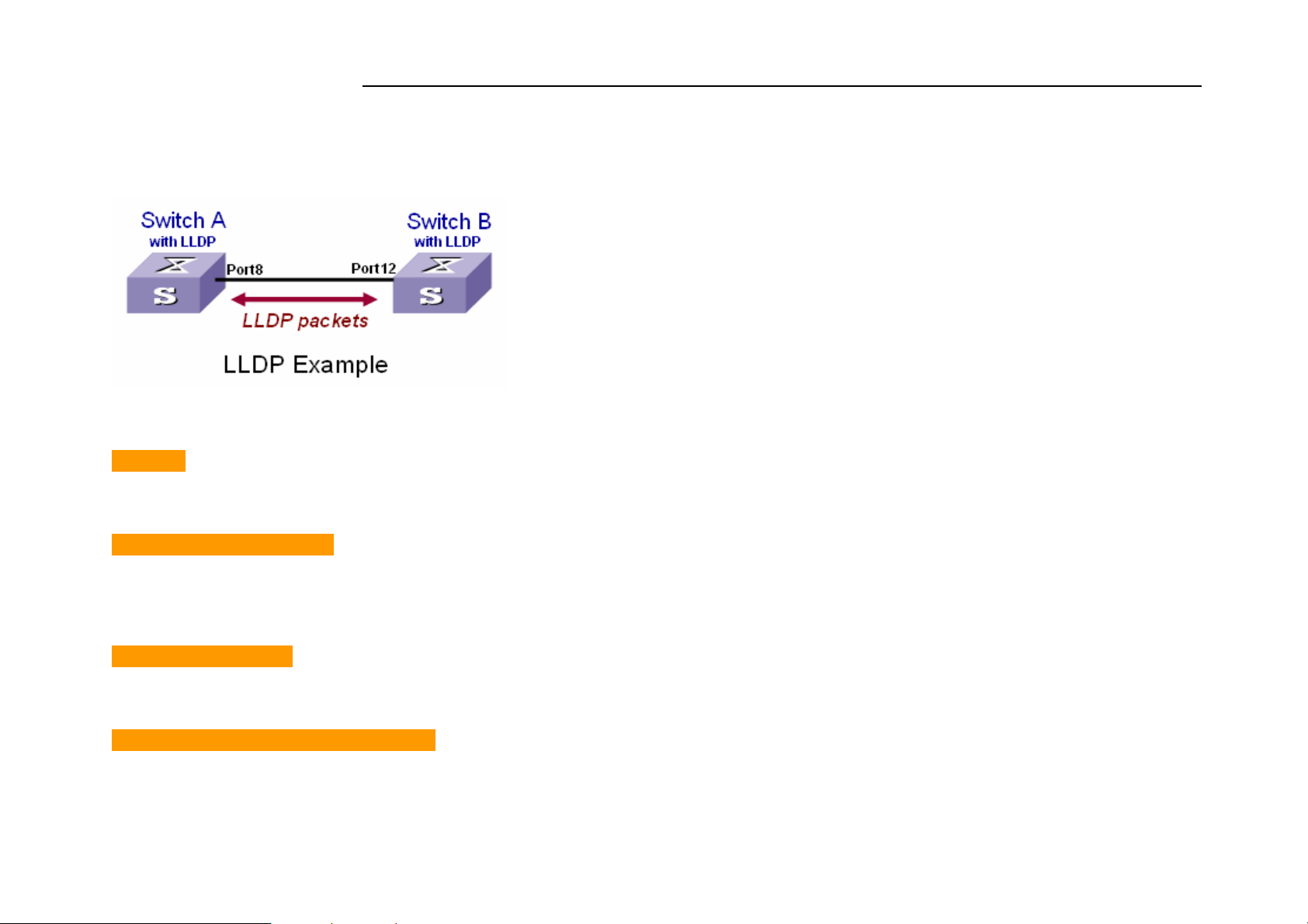
NV-1602S 16 Ports VDSL2 Managed IP DSLAM with Redundant Power USER’S MANUAL Ver.A2
The following figure is an example of LLDP connection:
LLDP Commands
[no] lldp
Enable/Disable LLDP global option
lldp hello-time <5-32768>
Set LLDP hello time which is the time interval between the transmission LLDP info packets. The range is from 5 to 32768
seconds. Default is 30 seconds.
lldp hod-time <2-10>
Set LLDP hold time. The range is from 2 to 10. Default is 4.
lldp port <rx|tx|both> [<PORT-LIST>]
Set LLDP port-based receive and transmit packet mode.
97
Page 99

NV-1602S 16 Ports VDSL2 Managed IP DSLAM with Redundant Power USER’S MANUAL Ver.A2
Parameters:
<rx|tx|both> rx: the port only receive LLDP packets; tx: the port only transmit LLDP packets;
both: the port can receive and transmit LLDP packets.
[<PORT-LIST>] specifies the ports to be set. If not specified, all ports are set.
no lldp port [<PORT-LIST>]
Disable LLDP port-based receive and transmit packet mode.
Parameters:
[<PORT-LIST>] specifies the ports to be set. If not specified, all ports are set.
show lldp
Show the LLDP global option, all the ports configuration and the neighbor’s information.
show lldp port [<PORT-LIST>]
show LLDP port configuration and the neighbor’s information..
Parameters:
[<PORT-LIST>] specifies the ports to be set. If not specified, all ports are set.
An LLDP example refer to the figure in previous page, the following commands will be used:
lldp (for switch A & B)
lldp port both 8 (for switch A)
lldp port both 12 (for switch B)
show lldp port 8 (for switch A to see the switch B’s LLDP info learned by Switch A)
98
Page 100

NV-1602S 16 Ports VDSL2 Managed IP DSLAM with Redundant Power USER’S MANUAL Ver.A2
Port8 Information
State : RX and TX
Pkt Tx : 3868
Pkt Rx : 46409
Neighbor Count : 1
Neighbor 1 information
TTL Time : 5879
Class ID : 56:78:17:45:25:00
Port ID : port(12)
System Name :
System Description : Switch v2.16
Port Description : Port 12
Port SetSpeed : Auto
Port ActualSpeed : FULL-100
99
 Loading...