

Page 1

NT205B
5
5
5
.
.
.
7
7
7
M
M
M
b
b
b
p
p
p
s
s
s
G
G
G
.
.
.
s
s
s
h
h
h
d
d
d
s
s
s
l
l
l
b
b
b
i
i
i
s
s
s
L
L
L
A
A
A
N
N
N
E
E
E
x
x
x
t
t
t
e
e
e
n
n
n
d
d
d
e
e
e
r
r
r
w
w
w
i
i
i
t
t
t
h
h
h
4
4
4
E
E
E
t
t
t
h
h
h
e
e
e
r
r
r
n
n
n
e
e
e
t
t
t
U
U
U
s
s
s
e
e
e
r
r
r
’
’
’
s
s
s
M
M
M
a
a
a
n
n
n
u
u
u
a
a
a
l
l
l
Page 2

NT205B User’s Manual
VER_A1
2
Copyright
Copyright © 2011 by National Enhance Technology Corp. All rights reserved.
Trademarks
NETSYS is a trademark of National Enhance Technology Corp.
Other brand and product names are registered trademarks or trademarks of their respective holders.
Legal Disclaimer
The information given in this document shall in no event be regarded as a guarantee of conditions or characteristics. With respect
to any examples or hints given herein, any typical values stated herein and/or any information regarding the application of the
device, National Enhance Technology Corp. hereby disclaims any and all warranties and liabilities of any kind, including without
limitation warranties of non-infringement of intellectual property rights of any third party.
Statement of Conditions
In the interest of improving internal design, operational function, and/or reliability, NETSYS reserves the right to make changes to
the products described in this document without notice. NETSYS does not assume any liability that may occur due to the use or
application of the product(s) or circuit layout(s) described herein.
Maximum signal rate derived form IEEE Standard specifications. Actual data throughput will vary. Network conditions and
environmental factors, including volume of network traffic, building materials and construction, and network overhead lower actual
data throughput rate.
Page 3

NT205B User’s Manual
VER_A1
3
Safety Warnings
For your safety, be sure to read and follow all warning notices and instructions before device use.
DO NOT open the device or unit. Opening or removing covers can expose you to dangerous high voltage points or other
risks. ONLY qualified service personnel can service the device. Please contact your vendor for further information.
Use ONLY the dedicated power supply for your device. Connect the power cord or power adaptor to the right supply voltage
(110V AC in North America or 230V AC in Europe).
DO NOT use the device if the power supply is damaged as it might cause electrocution. If the power supply is damaged,
remove it from the power outlet. DO NOT attempt to repair the power supply. Contact your local vendor to order a new power
supply.
Place connecting cables carefully so that no one will step on them or stumble over them. DO NOT allow anything to rest on
the power cord and do NOT locate the product where anyone can work on the power cord.
DO NOT install nor use your device during a thunderstorm. There may be a remote risk of electric shock from lightning.
DO NOT expose your device to dampness, dust or corrosive liquids.
DO NOT use this product near water, for example, in a wet basement or near a swimming pool.
Connect ONLY suitable accessories to the device.
Make sure to connect the cables to the correct ports.
DO NOT obstruct the device ventilation slots, as insufficient airflow may harm your device.
DO NOT store things on the device.
DO NOT use the device outside, and make sure all the connections are indoors. There may be a remote risk of electric
shock from lightning.
Be careful when unplugging the power, because the transformer may be very hot.
Keep the device and all its parts and accessories out of children’s reach.
Clean the device using a soft and dry cloth rather than liquid or atomizers. Power off the equipment before cleansing it.
This product is recyclable. Dispose of it properly.
Page 4

NT205B User’s Manual
VER_A1
4
Table of Contents
COPYRIGHT........................................................................................................................................................................................................ 2
SAFETY WARNINGS..........................................................................................................................................................................................3
CHAPTER 1. DESCRIPTION............................................................................................................................................................................ 6
1.1 P
RODUCT DESCRIPTION
.................................................................................................................................................................................. 6
1.2 S
PECIFICATION
............................................................................................................................................................................................... 7
1.3 A
PPLICATION
.................................................................................................................................................................................................. 8
1.4 SHDSL
SYSTEM COMPONENTS
....................................................................................................................................................................... 8
1.5 F
RONT PANEL
LEDS I
NDICATORS
................................................................................................................................................................... 8
1.6 R
EAR PANEL CONNECTORS
.......................................................................................................................................................................... 10
CHAPTER 2. PACKAGING ............................................................................................................................................................................. 12
2.1 C
HECKING PACKAGE CONTENTS
.................................................................................................................................................................. 12
2.2 P
REPARE FOR INSTALLATION
........................................................................................................................................................................ 12
CHAPTER 3. LOG ON...................................................................................................................................................................................... 13
3.1 M
ENU TREE
.................................................................................................................................................................................................. 15
3.2 M
AIN MENU
................................................................................................................................................................................................. 17
3.3 C
ONSOLE SCREEN CONVENTION
.................................................................................................................................................................. 17
CHAPTER 4. CONFIGURATION ................................................................................................................................................................... 19
4.1 C
ONFIGURE DEVICE TYPE
............................................................................................................................................................................ 21
4.2 C
ONFIGURE ANNEX MODE
........................................................................................................................................................................... 21
Page 5

NT205B User’s Manual
VER_A1
5
4.3 C
ONFIGURE
DSL R
ATE
................................................................................................................................................................................ 21
4.4
CONFIGURE
LAN I
NTERFACE
....................................................................................................................................................................... 21
4.5 VLAN
SETTING
............................................................................................................................................................................................ 23
4.6 F
ACTORY DEFAULT SETTING
........................................................................................................................................................................ 25
4.7 S
AVE CONFIGURATION
................................................................................................................................................................................. 25
CHAPTER 5. PERFORMANCE MONITORING.......................................................................................................................................... 26
CHAPTER 6. INVENTORY.............................................................................................................................................................................. 28
APPENDIX A: COMPLIANCE AND SAFETY INFORMATION................................................................................................................ 29
Page 6
NT205B User’s Manual
VER_A1
6
Chapter 1.
Description
1.1 Product Description
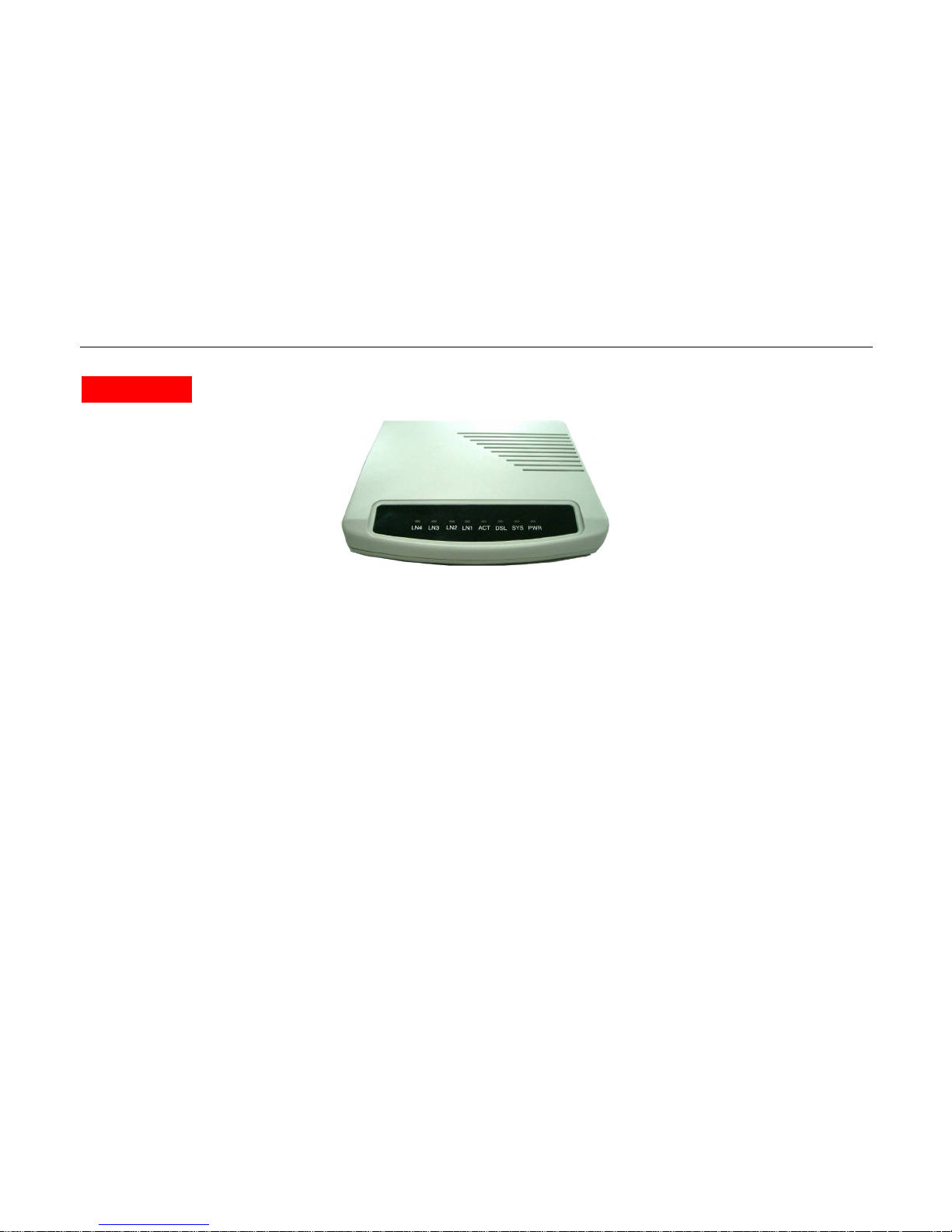
The NT205B, a SHDSL (Single-pair High-bit-rate Digital Subscriber Line) LAN Extender, provides a broadband transmission with
bandwidth up to 5.696Mbps over a single pair of copper wires for LAN connection between two local area networks. NT205B
provides a console port for users to configure the settings and to monitor the DSL connection status.
NT205B conforms to ITU-T G.991.2, the GSHDSL requirements. Each NT205B can be configured as either STU-C for the central
side or STU-R for the remote side. A pair of NT205B offers a cost effective symmetrical broadband solution for bandwidth-hungry
applications such as LAN-to-LAN connection, Internet, etc.
Features:
ITU G.991.2 Annex A, Annex B and Annex F
Symmetrical downstream and upstream data rates from 192Kbps to 5.696Mbps
Auto-Negotiation for 10/100 BaseT
Auto-MDIX for Auto Ethernet Tx/Rx Swap
Page 7

NT205B User’s Manual
VER_A1
7
1.2 Specification
G.SHDSL line
Line Coding: 16 TC-PAM or 32 TC-PAM
Line Rate: 192K bps ~ 5696 Kbps
Standard: ITU-T G.991.2, Annex A, Annex B and Annex F selectable
LAN interface
Mac Address filtering bridge up to 2K Mac address learning
Bridge: IEEE 802.1D transport, self-learning
VLAN Tag based & Port Based
Bandwidth Control for Ethernet Port
Physical interfaces
4 x RJ45 10/100Mbs Ethernet ports
1 x RJ-11 port for G.SHDSL connection
One console port: DB-9 Female
DC 5 V power input
Page 8
NT205B User’s Manual
VER_A1
8
1.3 Application
Following Figure shows a point to point application for user interface LAN
Ethernet Bridging
1.4 SHDSL system components
NT205B modem (CO) or NT205B modem (RT) in a working pair.
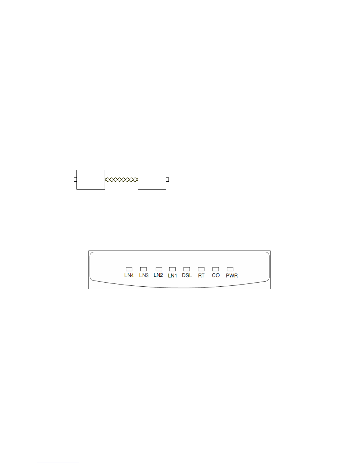
1.5 Front Panel LEDs Indicators
There are eight LED indicators on the front panel of NT205B. They show the statuses of the device.
LAN LAN
Page 9

NT205B User’s Manual
VER_A1
9
The functions of LED indicators are described in the following table:
LED
Color Status Meaning
PWR Orange
Steady
Off
The device is on.
The device is off.
CO Orange Steady The device is configured to CO mode
RT Orange Steady The device is configured to RT mode
DSL Orange
Steady
Blinking
Off
The device is Sync Status.
The link is synchronizing - this may take several
minutes.
The device is unplugged or disconnected.
LN1 Orange Steady
Link 1 - The LAN connection is successfully
established.
LN2 Orange Steady
Link 2 - The LAN connection is successfully
established.
LN3 Orange Steady
Link 3 - The LAN connection is successfully
established.
LN4 Orange Steady Link 4 - The LAN connection is successfully established.
Page 10
NT205B User’s Manual
VER_A1
10
1.6 Rear Panel Connectors
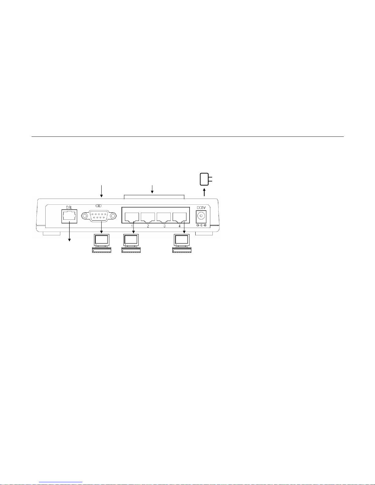
The rear panel connectors connecting the device to the LAN and xDSL network are illustrated as below.
LAN Interface characteristic
LAN Interface ( RJ-45 port ) located in NT205B’s rear panel meets to IEEE 802.3 or IEEE 802.3u request and supports 10/100
Base-T auto test and half/all touble works model operation, bridge can provide up to 128 MAC address and MAC address filtration
function, meets IEEE 802.1d protocol requirement.
RJ-45 wire
Figures separable shows as following :
Power Adapter
RJ-11
Phone Line
(xDSL)
RS-232
Emulator Terminal
VT-100
LAN
RJ-45
PC
Console
Rear Panel and Installation
PC
Page 11

NT205B User’s Manual
VER_A1
11
RJ-45 pin out
Table1.14: 10/100 Base-T pin out
Pin NO.
Function Data Direction Designati
on
1
TX Transmitting
Data
Toward the LAN network
TX+
2
TX Transmitting
Data
Toward the LAN network
TX-
3
RX Receiving
Data
Toward the LAN
Equipment
RX+
6
RX Receiving
Data
Toward the LAN
Equipment
RX-
8
1
Page 12

NT205B User’s Manual
VER_A1
12
Chapter 2.
Packaging
2.1 Checking Package Contents
NT205B Desktop is shipped with the following contents:
One 110/220V power adaptor
One NT205B User Manual
2.2 Prepare for Installation
Connecting the NT205B
If configured from the Craft port, your are encouraged to use the virtual terminal emulator from Window / Microsoft and set the COM
Port of PC to the following communication parameters:
DTE speed 38.4Kbps
8 Data Bit
Non – Parity Bit
One Stop Bit
No Flow Control
Selection of “VT100“ for Terminal Configuration
Page 13

NT205B User’s Manual
VER_A1
13
Chapter 3.
Log On
To access the VT-100 console screen, check that the CID port speed matches the terminal emulation program currently being used.
The default value for the CID port is 38.4k bps, 8 data bit, No Parity, 1 stop bit. The VT-100 console uses a blinking cursor to select
various menus, sub menus and fields within those menus.
To pop up the console, press the “ Enter “ key several times to display the Log On Screen illustrated in the following screen.
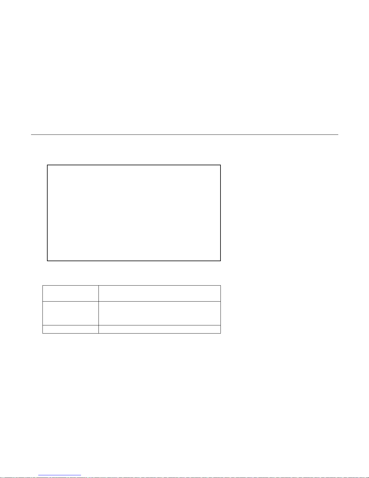
\Main
Device Type Line CNT Data Rate Port 1 Port 2 Port 3 Port 4
L: COT SYNC 4032 kbps LINK DOWN DOWN DOWN
R: RT SYNC 4032 kbps LINK DOWN LINK DOWN
==========================================================================
1. Configration <DIR>
2. Status <DIR>
3. Inventory <DIR>
---------------------------------------------------------------------------------------------------------------------------------
1..3] Select Item Enter] Accept Item ESC]Escape Ctrl-R] Screen Refresh
Main Screen
Page 14

NT205B User’s Manual
VER_A1
14
Cursor Operation
To select a specific field or navigate the console screen, refer to the table below for further details.
Keyboard
Command
Description
Tab
Tabs to previous item.
Space
Refreshes the entire screen.
Esc
Escapes to previous page
1 …N]
Fields enclosed in brackets [ ] offer a list
of selections.
Enter
Validates the fields selected..
Page 15
NT205B User’s Manual
VER_A1
15
3.1 Menu Tree
Viewing from Main Menu, the second layer “ 1. Configuration, 2.Status and 3. Inventory “ and all its tributary parameters are shown in
Figure 3.1.
Figure 3.1: Menu Tree
Main Menu
>> 1. Configuration
>> 1. Device Type COT; RT
>> 2. Annex Annex A; Annex B; Annex F
>> 3. DSL Rate 3~89 (AnnexF) 3~36 (Annex A, B)
>> 4. LAN Port
>> 1. Speed 10M; 100M
>> 2. Auto Negotiation Disable; Enable
>> 3. Duplex Half; Full
>> 4. Flow control Eable; Disable
>> 5. VLAN setting
>> 1. VLAN Mode Unaware; Aware
>> 2. P-P Segmented Channel Disable; Enable
>> 3. Ingress VID Range Start 0 ( 0 ~ 4096)
>> 4. Ingress VID Range Lenght 0 ( 0 ~ 16)
>> 5. Port 1 Bandwidth Value 1~ 89 , N*64Kbps
>> 6. Port 2 Bandwidth Value 1~ 89 , N*64Kbps
>> 7. Port 3 Bandwidth Value 1~ 89 , N*64Kbps
Page 16
NT205B User’s Manual
VER_A1
16
>> 8. Port 4 Bandwidth Value 1~ 89 , N*64Kbps
>> 6. Factory Default
>> 7. Save
>> 2. Status
>> 1. Device Type COT; RT
>> 2. Annex Annex A; Annex B; Annex F
>> 3. DSL Rate 64~5696 kbps
>> 4. S/N (0~20dB)
>> 5. DSL Status
Idel; SYN; Handshaking;
Trainning
>> 3. Inventory
>> 1. H/W version
>> 2. S/W version
Page 17
NT205B User’s Manual
VER_A1
17
3.2 Main Menu
The Main Menu Screen, illustrated below,
3.3 Console Screen Convention
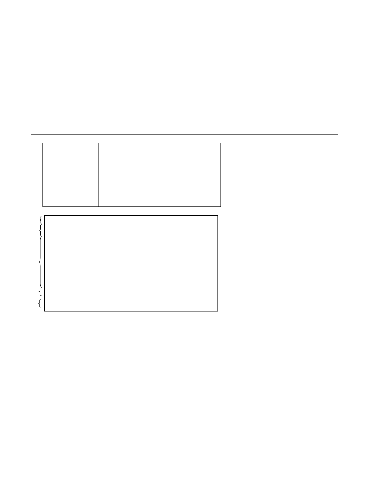
The Console Screen Convention contains five user operating areas.
Menu Sequence:
The one-line top most
area that shows sequence for
bringing the menu to the current hierarchy.
Status/ Alarm
message:
This is the two-line area above the double dotted
line that provides network and user interface status
and alarm message.
Sub-Menu or Result
This is the area above the single dotted line that
\Main
Device Type Line CNT Data Rate Port 1 Port 2 Port 3 Port 4
L: COT SYNC 4032 kbps LINK DOWN DOWN DOWN
R: RT SYNC 4032 kbps LINK DOWN LINK DOWN
==========================================================================
1. Configration <DIR>
2. Status <DIR>
3. Inventory <DIR>
---------------------------------------------------------------------------------------------------------------------------------
1..3] Select Item Enter] Accept Item ESC]Escape Ctrl-R] Screen Refresh
Page 18
NT205B User’s Manual
VER_A1
18
Display:
provides content of sub-menu or display of
performance data and testing result.
Input field:
The area beneath the dotted line
that shows options
specific to menu or sub-
menu items and allows user
to enter value desired.
Function Keys:
The area right beneath the input field that lists the
function keys specific to the operation of the menu
currently displayed.
Function Key
Input Field
Sub-Menu
Result Display
Status Message
Menu Sequence
\Main\ Cfg
Device Type Line CNT Data Rate Port 1 Port 2 Port 3 Port 4
L: COT SYNC 4032 kbps LINK DOWN DOWN DOWN
R: RT SYNC 4032 kbps LINK DOWN LINK DOWN
==========================================================================
1. Device Type : COT
2. Annex : Annex A
3. DSL Rate : 03
4. LAN port <DIR>
5 VLAN Setting <DIR>
6. Factory Ddfault <CMD>
7. Save <CMD>
---------------------------------------------------------------------------------------------------------------------------------
1). COT, 2) RT
Input: 1
1..6] Select Item Enter] Accept Item ESC]Escape Ctrl-R] Screen Refresh
Page 19

NT205B User’s Manual
VER_A1
19
Chapter 4.
Configuration
This chapter provides instructions on how to access and configure your NT205B, displaying configuration options, restoring to
factory default and saving the configuration.
In other words, the provisioning parameters for each SHDSL unit could also only be provided through the CID and NT205B Desktop
functioning as STU-C. or as STU-R. In case of STU-R is connected to STU-C successfully then the DSL rate of STU-R will be
changed as same as STU-Cs automatically. Please pay attention to the following notice.
1. Regional DSL modes - Annex A/B/F of STU-C and STU-R shall be set as the same. Otherwise the DSL can not get sync.
2. Given the same speed under 2304kbps, the transmission distance working in Annex A (or Annex B) is around 300 meters longer
than working in Annex F at AWG26 wire. This is the testing result in a specific environment, for your reference only. User shall
carefully set the regional mode for optimizing DSL reach or speed.
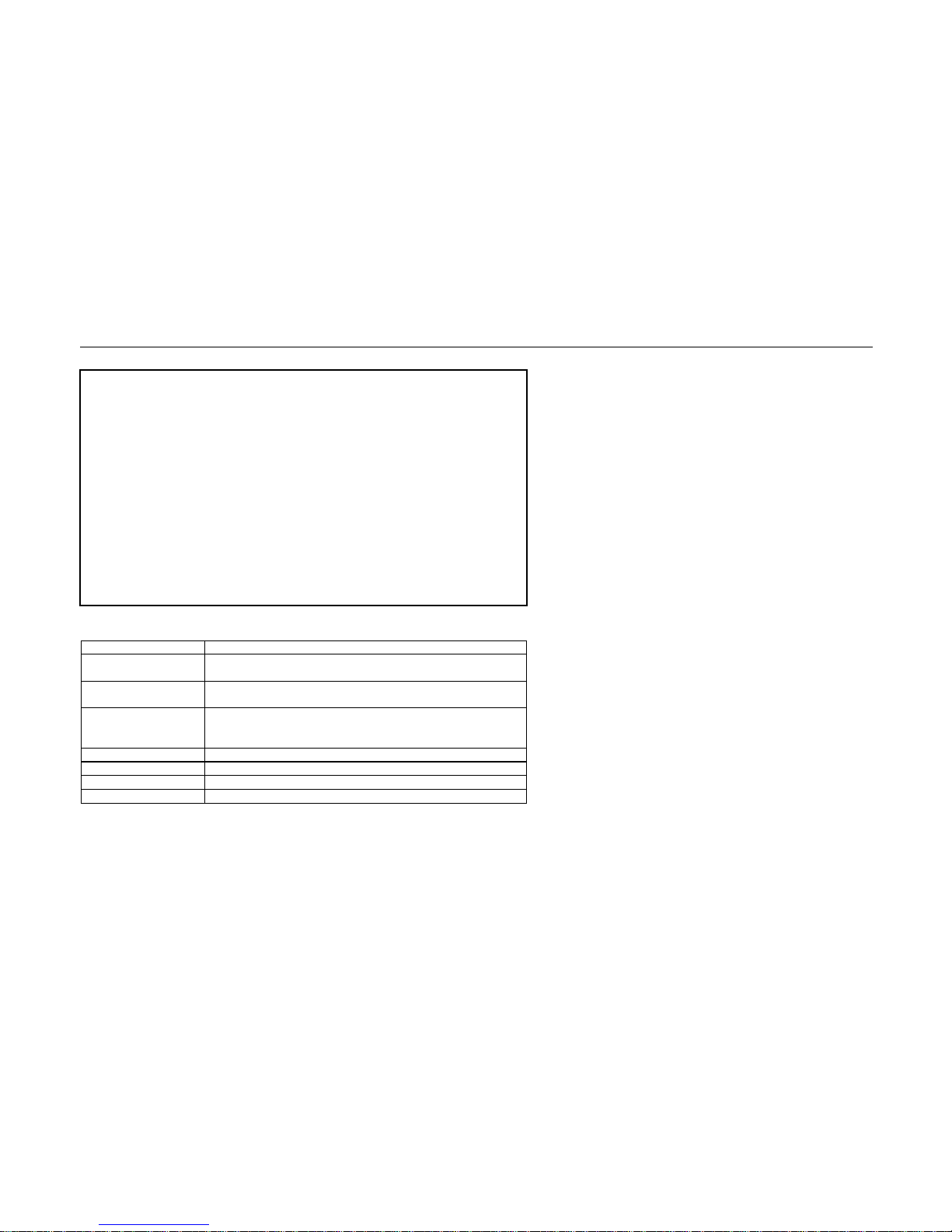
The first Item on the Main Menu Screen is “ Configuration “ option. The Configuration Screen below allows you to view, set or make
changes to certain specific parameters about the unit in service.
The following Screen allows you to view and change the parameters of NT205B.
Page 20
NT205B User’s Manual
VER_A1
20
\Main\ Cfg
Device Type Line CNT Data Rate Port 1 Port 2 Port 3 Port 4
L: COT SYNC 4032 kbps LINK DOWN DOWN DOWN
R: RT SYNC 4032 kbps LINK DOWN DOWN DOWN
==========================================================================
1. Device Type : COT
2. Annex : Annex A
3. DSL Rate : 03
4. LAN port <DIR>
5 VLAN Setting <DIR>
6. Factory Ddfault <CMD>
7. Save <CMD>
---------------------------------------------------------------------------------------------------------------------------------
1). COT, 2) RT
Input: 1
1..6] Select Item Enter] Accept Item ESC]Escape Ctrl-R] Screen Refresh
Table
5.1
Configure Parameters Screen Content
Item Description
1. Device Type
Specifies whether the unit is configured as COT, or RT.
Entry: COT; RT
2. Annex
Sets the transmission mode for SHDSL.
Entry: Annex A; Annex B; Annex F
3. DSL Rate
Specifies data rate for DSL. Data rate could be configured in
multiple of 64k. For Annex A or B ,N= 3 ~ 36, For Annex F,
N=3~89.
4. LAN Port
Configure LAN Port
5. VLAN Setting
Configure the VLAN and Bandwidth control of 4 LAN port
6. Factory Default
Sets SHDTU03B-ET100BS to factory default
7. Save
Save the parameters to SHDTU03B-ET100BS
Page 21

NT205B User’s Manual
VER_A1
21
4.1 Configure Device Type
To configure the Device Type , apply the menu selection sequence: Local >> Configure. Move cursor to 1. Device Type and specify
whether the unit is configured as COT, or RT.
4.2 Configure Annex Mode
To configure the Annex Mode , apply the menu selection sequence: Local >> Configure. Move cursor to 2. Annex and specify
whether the DSL is configured as Annex A, Annex B or Annex F.
4.3 Configure DSL Rate
To configure the DSL Rate , apply the menu selection sequence: Local >> Configure. Move cursor to 3. DSL Rate and Specifies
data rate for DSL. Data rate could be configured in multiple of 64k. For Annex A or B, N= 3 ~ 36, For Annex F, N=3~89.
4.4 Configure LAN Interface
To access LAN Port, apply the menu selection sequence: Local >> Configure >> LAN port >> as shown below.
Page 22

NT205B User’s Manual
VER_A1
22
\Mainl\ Cfg\LAN Port
Device Type Line CNT Data Rate Port 1 Port 2 Port 3 Port 4
C: COT SYNC 4032 kbps LINK DOWN DOWN DOWN
R: RT SYNC 4032 kbps LINK DOWN DOWN DOWN
==========================================================================
1. Auto Negotiation : Disable
2. Speed : 100M
3. Duplex : Full
4. Flow control : Enable
---------------------------------------------------------------------------------------------------------------------------------
1). Disable, 2) Enable
Input: 1
1..4] Select Item Enter] Accept Item ESC]Escape Ctrl-R] Screen Refresh
Page 23
NT205B User’s Manual
VER_A1
23
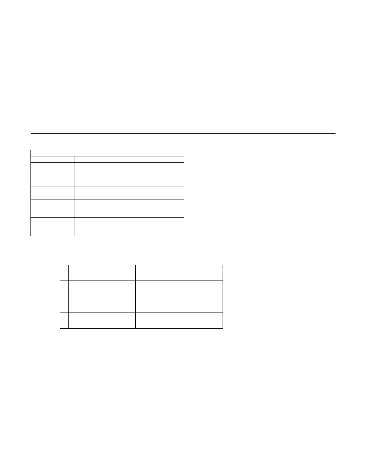
The Ethernet interface parameters, described now, are provided in the following table.
Table 5.2: LAN Port Screen Content
Item Description
1. Auto
Negotitation
Specifies whether the Ethernet interface is
being operating in auto-detecting or Manually
mode.
Entry: Disable; Enable
2. Mode Specifies the operating speed of LAN port
Entry: 10M; 100M
3. Duplex Specifies whether the Ethernet interface is
being operating in Half or Full duplex mode.
Entry: Half; Full
4. 802.3 flow
control
Specifies whether the flow control is enabled
or
not.
Entry: Enable; Disable
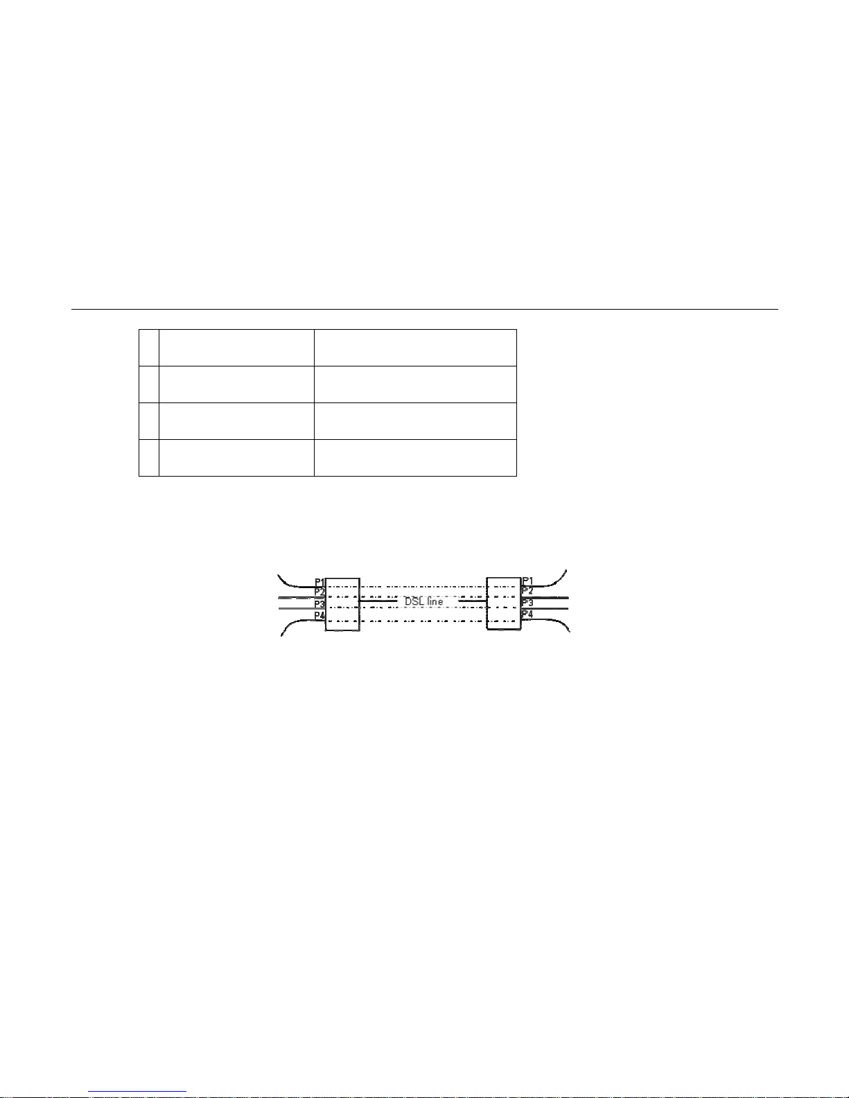
4.5 VLAN setting
>> 5. VLAN setting
>> 1. VLAN Mode
Unaware ; Aware
>> 2. P-P Segmented
Channel
Disable ; Enable
>> 3. Ingress VID Range
Start
0 ( 0 ~ 4096)
>> 4. Ingress VID Range
Lenght
0
Page 24
NT205B User’s Manual
VER_A1
24
>> 5. Port 1 Bandwidth
Value
1~ 89 , N*64Kbps
>> 6. Port 2 Bandwidth
Value
1~ 89 , N*64Kbps
>> 7. Port 3 Bandwidth
Value
1~ 89 , N*64Kbps
>> 8. Port 4 Bandwidth
Value
1~ 89 , N*64Kbps
Default configuration setup is VLAN unaware, customers can enable the VLAN by select the VLAN mode as “Aware”.
There are two kind of VLAN implementation, one is the P-P Segmented Channel and the other is Tag based Vlan. These two
implementation of VLAN can NOT work together. User should configure one option at one time.
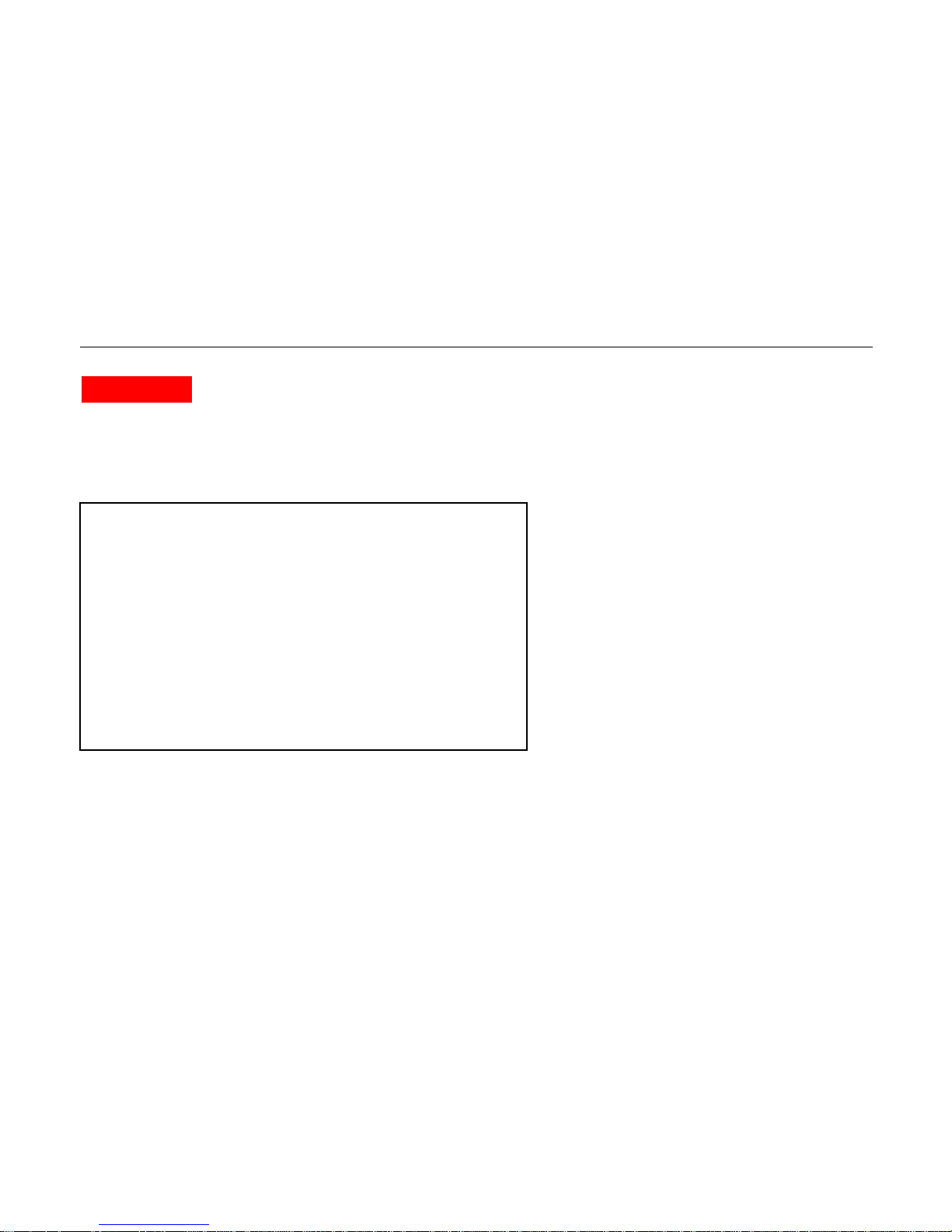
For P-P segmented Channel implement, there is a typical application:
The LAN ports P1 … P4 at two locations are working like P1 --- P1, P2 --- P2 … 4 separated Ethernet lines.
Customer can set the LAN Port1~4 Bandwidth when the P-P Segmented Channel mode is selected. The priority for the bandwidth
control between the 4 LAN port is :
The higher bandwidth value, the higher priority.
1) If the total bandwidth of the 4 port is less than the DSL connected rate, then bandwidth of every Port will be guaranteed.
Page 25

NT205B User’s Manual
VER_A1
25
2) When the total bandwidth of the 4 port is larger than the DSL connected rate, then the port with higher bandwidth setting will be
satisfied firstly.
For the VLAN tage mode, the customer can assign the VID range which are allowed to pass and the VID which are not in this range
will be discarded. For example, the ingrass VID Start = 3, and ingrass VID length is 10, then Ethernet packets with the VID between 3
and 12 will be allowed to pass, and the others will be discarded.
4.6 Factory Default setting
Default configuration setup is provided. To default the setting, follow the steps described below.
The “ Local\Cfg.” screen appears when the Local\Configuration menu sequence is entered. Position the cursor at option 5 “ Factory
Default “ of Configuration menu and press “ Enter “ to restore setting to factory default. After setting default value, the system
prompts you for a “ Set default succeed ! Press any key to continue..” message displayed in reverse video.
4.7 Save configuration
Regardless of STU-C or STU-R, NT205B is provided with 2M byte non-volatile flash memory which stores all provisioning
parameters of the unit.
When change are made to the selection option through the Configuration\Save sequence, the changes must be saved to take effect.
Page 26
NT205B User’s Manual
VER_A1
26
Chapter 5.
Performance Monitoring
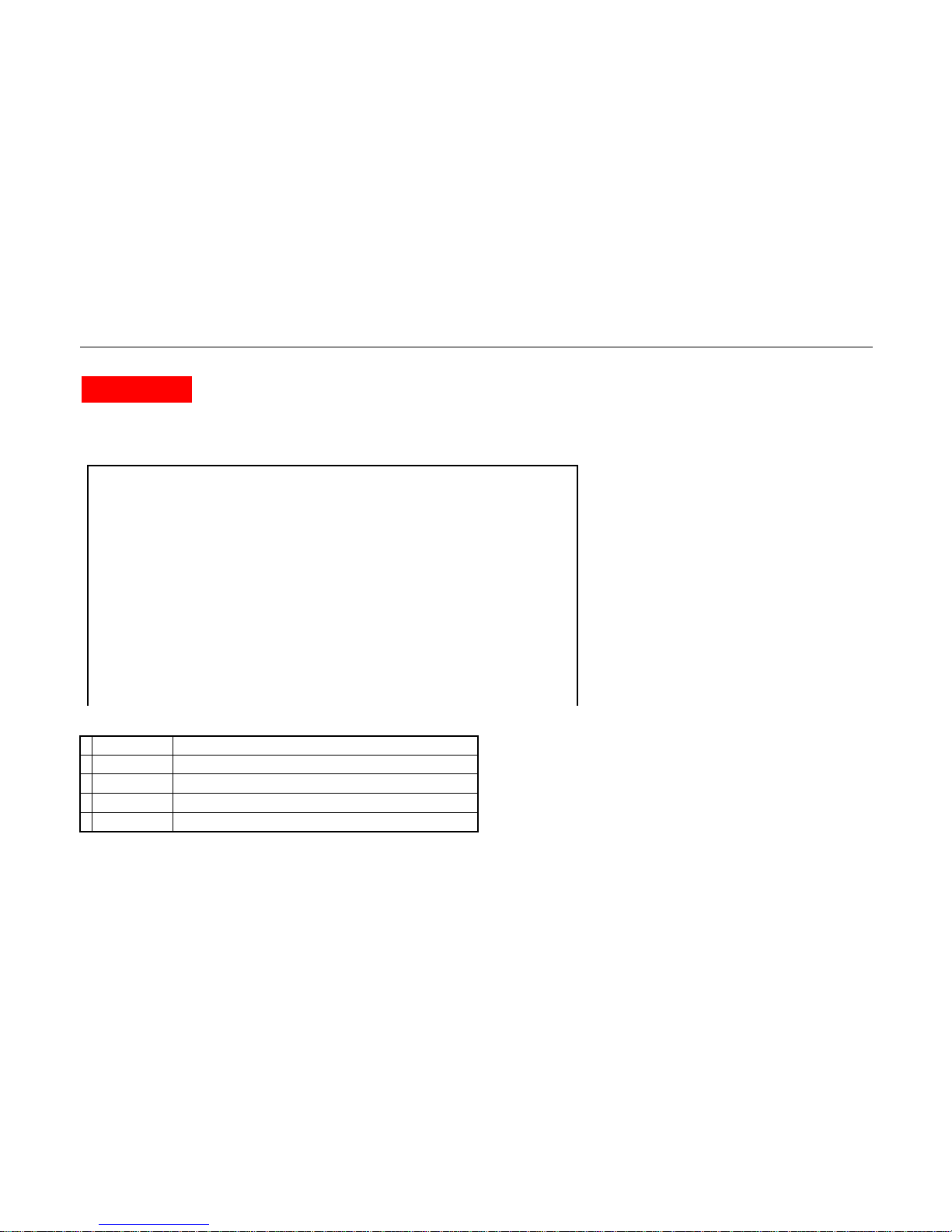
This chapter provides information on the display the status of NT205B that include the data rate of DSL, current signal-to-noise ration
(SNR), the status of DSL and displaying the total number of received/transmitted Packets for each LAN port, follow the menu
entering sequence: Local >>> Statue
\Main\ Status
Device Type Line CNT Data Rate Port 1 Port 2 Port 3 Port 4
C: COT SYNC 4032 kbps LINK DOWN DOWN DOWN
R: RT SYNC 4032 kbps LINK DOWN DOWN DOWN
==========================================================================
1. Device Type : COT
2.
Annex : Annex A
3. DSL Rate : 4032Kbps
4. S/N : 30
5. DSL status : Synch
6. LAN 1 Rx/Tx packet : 0 : 0
7 LAN 2 Rx/Tx packet : 0 : 0
8 LAN 3 Rx/Tx packet : 0 : 0
9 LAN 4 Rx/Tx packet : 0 : 0
---------------------------------------------------------------------------------------------------------------------------------
1..5] Select Item Enter] Accept Item ESC]Escape Ctrl-R] Screen Refresh
Page 27

NT205B User’s Manual
VER_A1
27
Table 6.1: Display Status Screen Content
Item
1. Device Type
Description
Displays the Device Type which you set SHDTU03B-ET100BS
2. Annex
Displays the Annex mode which you set SHDTU03B-ET100BS
3. DSL Rate
Displays the DSL Rate.
4. S/N
Displays the current signal-to-noise ration (SNR)
5. DSL Status
Display the current DSL Status.
6. LAN 1 Rx/Tx packet
Displays the total number of received/transmitted Packets through the LAN port 1
7. LAN 2 Rx/Tx packet
Displays the total number of received/transmitted Packets through the LAN port 2
8. LAN 3 Rx/Tx packet
Displays the total number of received/transmitted Packets through the LAN port 3
9. LAN 4 Rx/Tx packet
Displays the total number of received/transmitted Packets through the LAN port 4
Page 28
NT205B User’s Manual
VER_A1
28
Chapter 6.
Inventory
This chapter provides identity information for the unit’s services and revision state as illustrated in the figure below. To access this
maintenance service, select “ 3. Inventory “ of main menu and hit “ Enter “ key to take effect.
Item Description
1 S/W Version : Displays the software version currently used for
2
H/W Version : Displays the hardware version of circuitry.
3 DSL Vserion : Displays the DSL version of circuitry.
\Main\ Inventory
Device Type Line CNT Data Rate Port 1 Port 2 Port 3 Port 4
C: COT SYNC 4032 kbps LINK DOWN DOWN DOWN
R: RT SYNC 4032 kbps LINK DOWN DOWN DOWN
=============================================================
1
.
H/W version : 1.3
2
.
S/W version : 1.4
3
.
DSL version : 06.00.02
1..3] Select Item Enter] Accept Item ESC]Escape Ctrl-R] Screen Refresh
Page 29

NT205B User’s Manual
VER_A1
29
Appendix A: Compliance and Safety Information
FCC Radio Frequency Interference Statement
This equipment has been tested and found to comply with the limits for a computing device, pursuant to Part 15 of FCC
rules. These limits are designed to provide reasonable protection against harmful interference when the equipment is
operated in a commercial environment. This equipment generates uses and can radiate radio frequency energy and, if not
installed and used in accordance with the instructions, may cause harmful interference to radio communications. However,
there is no guarantee that interference will not occur in a particular installation. If this equipment does cause harmful
interference to radio or television reception, which can be determined by turning the equipment off and on, the user is
encouraged to try to correct the interference by one or more of the following measures:
1. Reorient or relocate the receiving antenna.
2. Increase the separation between the equipment and receiver.
3. The equipment and the receiver should be connected to outlets on separate circuits.
4. Consult the dealer or an experienced radio/television technician for help.
Changes or modifications not expressly approved by the party responsible for compliance could void the user’s authority to
operate the equipment.
If this telephone equipment causes harm to the telephone network, the telephone company will notify you in advance that
temporary discontinuance of service may be required. But if advance notice isn’t practical, the telephone company will
notify the customer as soon as possible. Also, you will be advised of your right to file a complaint with the FCC if you believe
it is necessary.
The telephone company may make changes in its facilities, equipment, operations or procedures that could affect the
Page 30

NT205B User’s Manual
VER_A1
30
proper functioning of your equipment. If they do, you will be notified in advance in order for you to make necessary
modifications to maintain uninterrupted service.
This equipment may not be used on coin service provided by the telephone company. Connection to party lines is subject to
state tariffs.
Important Safety Instructions
Caution: The direct plug-in wall transformer serves as the main product for disconnecting. The socket outlet shall be
installed near the product and be readily accessible.
Caution: Use only the power supply included with this product. In the event the power supply is lost or damaged:In the
United States, use only with CSA certified or UL listed Class 2 power supply, rated 5Vdc.
IN Europe, use only with CE certified power supply, rated 5Vdc.
Do not use this equipment near water, for example in a wet basement.
Avoid using a telephone during an electrical storm. There may be a remote risk of electrical shock from lightning.
Do not use the telephone to report a gas leak in the vicinity of the leaking area.
If you experience trouble with this unit, please contact customer service of your dealer immediately.
DO NOT DISASSEMBLE THIS EQUIPMENT. It does not contain any user serviceable components.
Page 31
NT205B User’s Manual
VER_A1
31
FCC Warning
This equipment has been tested to comply with the limits for a Class A digital device, pursuant to Part 15
of the FCC Rules. These limits are designed to provide reasonable protection against harmful
interference when the equipment is operated in a commercial environment. This equipment can
generate, use, and radiate radio frequency energy and, if not installed and used in accordance with the
instruction manual, may cause harmful interference to radio communications. Operation of this equipment in a residential
area is likely to cause harmful interference in which case the user will be required to correct the interference at owner’s
expense.
CE Mark Warning
This is a class B product. In a domestic environment, this product may cause radio interference in which case
the user may be required to take adequate measures.
WEEE Warning
To avoid the potential effects on the environment and human health as a result of the presence of
hazardous substances in electrical and electronic equipment, end users of electrical and electronic
equipment should understand the meaning of the crossed-out wheeled bin symbol. Do not dispose of
WEEE as unsorted municipal waste and have to collect such WEEE separately.
 Loading...