

Page 1

MyNetGate 2000 (MNG -2000) Cable Modem Series
USER’S MANUAL
Copyright
@
2001 Net&Sys Co., Ltd.
All rights reserved. This users guide may not be reproduced, in part or in whole, without the
permission of Net&Sys. The content of this users guide is subject to change without notice in the
future. Net&Sys assumes no liability for damages resulting from the use of this product or the
information contained in this users guide
Trademarks
Microsoft, Windows95, 98 and windows NT are registered trademarks of Microsoft Corporation.
MyNetGate is trademarks of Net&Sys. All other trademarks and registered trademarks are the
property of their respective owners.
The user’s manual is made for MNG-2000 Series Cable Modem.
Revision
1.0
June
2001
Page 2
1
THIS DEVICE COMPLIES WITH PART 15 OF THE FCC RULES. OPERATION IS
SUBJECT TO THE FOLLOWING TWO CONDITIONS: (1) THIS DEVICE MAY NOT
CAUSE HARMFUL INTERFERENCE, AND (2) THIS DEVICE MUST ACCEPT ANY
INTERFERENCE RECEIVED, INCLUDING INTERFERENCE THAT MAY CAUSE
UNDESIRED OPERATION.
FCC Warning Statement
NOTE :
This equipment has been tested and found to comply with the limits for a Class B digital device,
pursuant to Part 15 of the FCC Rules. These limits are designed to provide reasonable protection
against harmful interference in a residential installation.
This equipment generates, uses and can radiate radio frequency energy and, if not installed and
used in accordance with the instructions, may cause harmful interference to radio
communications. However, there is no guarantee that interference will not occur in a particular
installation.
If this equipment does cause harmful interference to radio or television reception which can be
determined by turning the equipment off and on, the user is encouraged to try to correct the
interference by one or more of the following measures.
- Reorient or relocate the receiving antenna.
- Increase the separation between the equipment and receiver.
- Connect the equipment into an outlet on a circuit different from that to which the receiver is
connected.
- Consult the dealer or an experienced radio, TV technical for help.
- Only shielded interface cable should be used.
Finally, any changes or modifications to the equipment by the user not expressly approved by the
grantee or manufacturer could void the users authority to operate such equipment,
Page 3

2
Contents
Contents..............................................................................................................................................................................................2
1 Safety Precautions........................................................................................................................................................................4
2 Box Contents.................................................................................................................................................................................4
2.1 Other Requirements ...........................................................................................................................................................5
3 MNG-2000 Cable Modem Front...............................................................................................................................................5
3.1 POWER LED.....................................................................................................................................................................5
3.2 STATUS LED.......................................................................................................................................................................5
3.3 UP LED .................................................................................................................................................................................5
3.4 DOWN LED .........................................................................................................................................................................5
3.5 LAN LED ..............................................................................................................................................................................6
4 MNG-2000 Cable Modem Rear .................................................................................................................................................7
4.1 DC in Connector .................................................................................................................................................................7
4.2 USB Connector ....................................................................................................................................................................7
4.3 Ethernet Connector............................................................................................................................................................7
4.4 Cable Connector .................................................................................................................................................................8
5 Cable Modem Installation..........................................................................................................................................................8
6 Cable Modem Inspection............................................................................................................................................................9
6.1 Computer IP Address Verification .................................................................................................................................9
6.2 Check Points for Modem Problems .............................................................................................................................11
7 USB Network Driver Installation Guide.............................................................................................................................. 12
7.1 Install NetnSys Cable Modem USB Network Driver under Windows 98 and 98SE for the First Time.. 12
7.1.1 Install NetnSys Cable Modem USB Network Driver..........................................................................................12
7.1.2 Verifying Driver Installation....................................................................................................................................16
7.2 Install NetnSys Cable Modem USB Network Driver under Windows 2000 for the First Time................. 17
7.2.1 Install NetnSys Cable Modem USB Network Driver..........................................................................................17
7.2.2 Verifying Driver Installation....................................................................................................................................21
7.2.3 Uninstalling the driver..............................................................................................................................................24
8 Contact Information.................................................................................................................................................................27
Page 4

3
List of Figures
Figure 1 MNG-2000 Box Contents ...................................................................................................... 4
Figure 2 MNG-2000 Front View .......................................................................................................... 5
Figure 3 Cable Modem Rear View ........................................................................................................ 7
Figure 4 Ethernet Cable Wiring Diagram ............................................................................................. 8
Figure 5 Installation Setup ...................................................................................................................8
Figure 6 Run winipcfg program ............................................................................................................ 9
Figure 7 Select Adaptor (LAN Card)...................................................................................................10
Figure 8 Device Manager ....................................................................................................................11
Figure 9 Add New Hardware Wizard for windows 9x (Screen 1) .......................................................12
Figure 10 Add New Hardware Wizard for windows 98 (Screen 2)............................................................12
Figure 11 Selecting for the driver...........................................................................................................13
Figure 12 Driver Found (Screen 1) ........................................................................................................14
Figure 13 Driver Found (Screen 2) ........................................................................................................14
Figure 14 Copying Files ........................................................................................................................15
Figure 15 Installation Complete.............................................................................................................15
Figure 16 Reboot Prompt Dialog Box .....................................................................................................15
Figure 17 Network Neighborhood Property ............................................................................................16
Figure 18 “Ipconfig” Command............................................................................................................16
Figure 19 Added New Hardware Wizard for Windows 2000 .....................................................................17
Figure 20 Found New Hardware Wizard for Windows 2000 .....................................................................17
Figure 21 Searching for driver (Screen 1) ..............................................................................................18
Figure 22 Searching for a Driver (Screen 2)...........................................................................................18
Figure 23 Driver Search Results............................................................................................................19
Figure 24 Digital Signature Not Found ...................................................................................................19
Figure 25 Notification Screen ................................................................................................................20
Figure 26 Windows Desktop .................................................................................................................21
Figure 27 System Properties .................................................................................................................22
Figure 28 Hardware Properties..............................................................................................................22
Figure 29 Device Manager ....................................................................................................................23
Figure 30 Windows Desktop .................................................................................................................24
Figure 31 System Properties .................................................................................................................25
Figure 32 Device Manager ....................................................................................................................25
Figure 33 Device Manager ....................................................................................................................26
List of Tables
Table 1 LED Status Summary ............................................................................................................ 6
Page 5
4
1 Safety Precautions
①
Please do not damage the DC power adaptor or plug.
② Please do not connect the cable connector at the back of the cable modem to the TV antenna
cable. Only connect to the CATV network providing the cable Internet service.
③ The cable modem should be located on a safe, flat surface in a space with plenty of
ventilation.
④ Please do not place electronic equipment or other objects on top of the cable modem.
⑤ Net&Sys will not be responsible for damage incurred by user mishandling or misuse, or
opening of the product case.
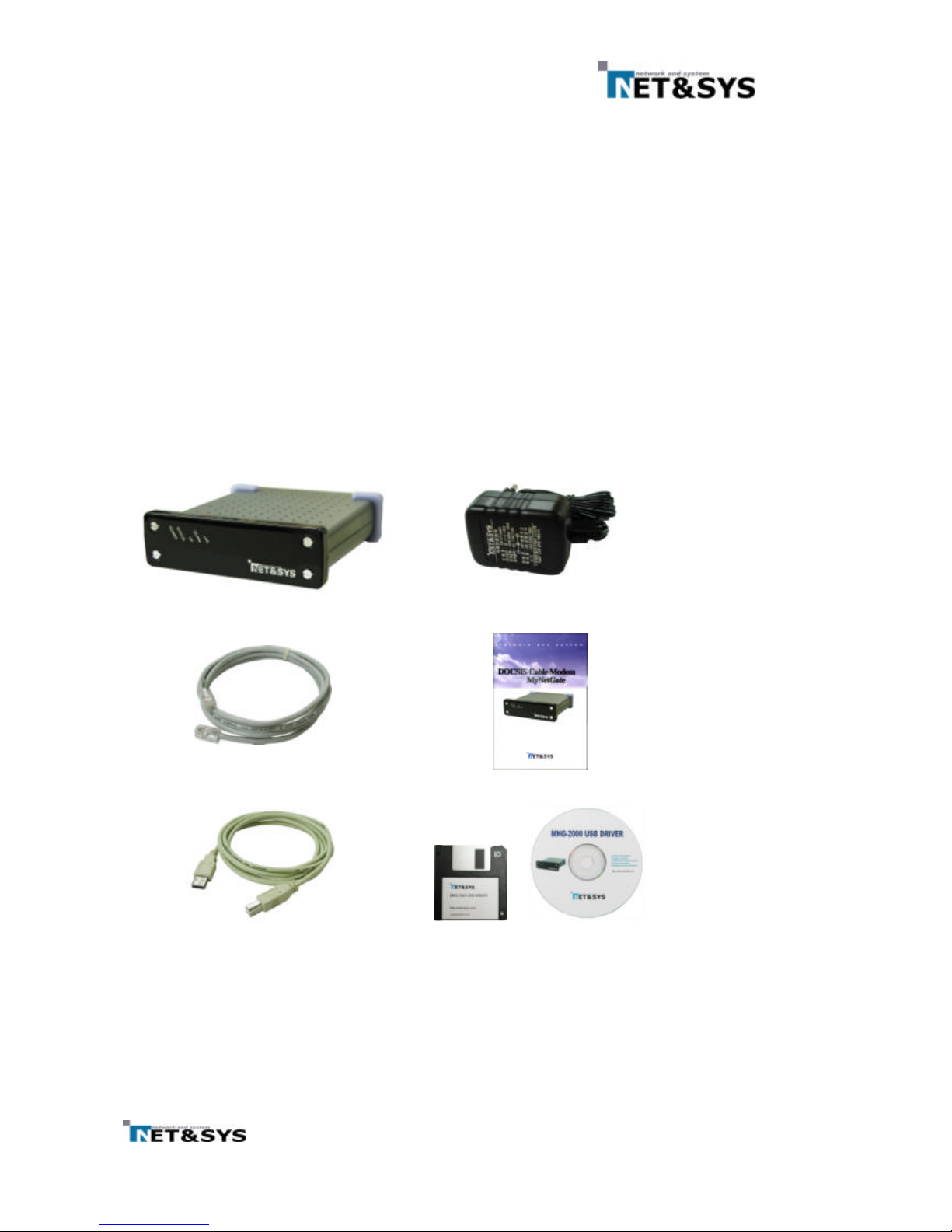
2 Box Contents
Please verify that the cable modem box contains the following.
Figure 1 MNG - 2000 Box Contents
Note : Please record the serial number and MAC address printed at the bottom of the cable
modem on the front page of the manual. This information will be required to place an A/S
request.
MNG-2000
DC adaptor
Ethernet Cable
Manual
USB Cable
(Optional)
Floppy Disc or CD ROM
(Optional)
Page 6
5
2.1 Other Requirements
①
The cable modem requires a user PC running
Windows 95/98/NT/2000 supporting TCP/IP,
DHCP/BOOTP protocols
② The user PC needs to have an Ethernet 10/100 Base-T LAN card installed. The LAN card
maybe be purchased by the user or supplied by the Internet Service Provider.
3 MNG-2000 Cable Modem Front
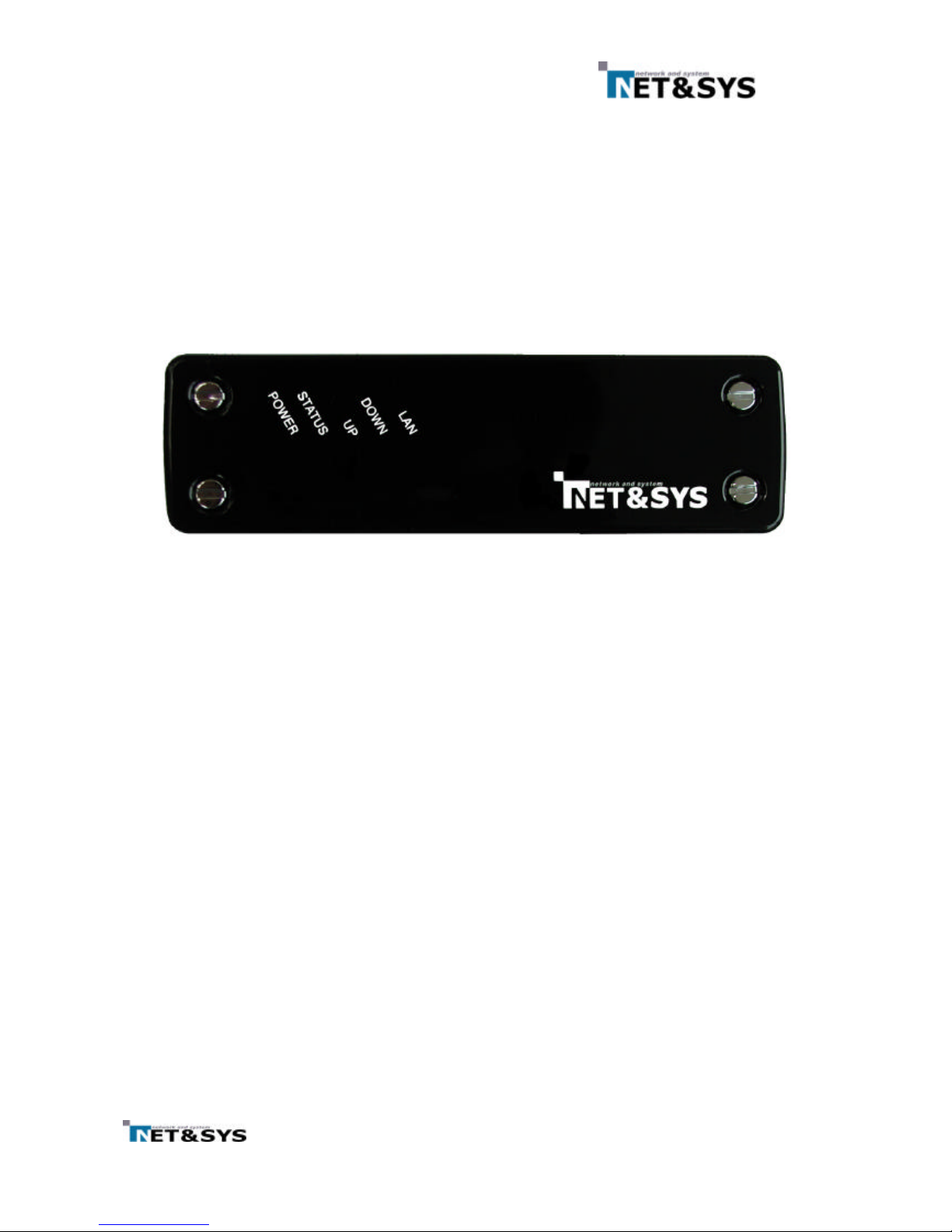
The front of the MNG-2000 cable modem include five LED’s that are marked POWER, STATUS, UP,
DOWN and LAN. These are used in indicating the operating status of the cable modem.
Figure 2 MNG- 2000 Front View
3.1
POWER LED
When the DC adaptor plug is connected and power applied to the MNG-2000 cable modem, all
five LED’s will light up briefly before the POWER LED lights up. This indicates that power has
been correctly applied to the modem.
While the POWER LED lights up, the cable modem copies its operating program from the flash
memory to the dram memory. The LED will remain constantly on as long as power is applied.
3.2
STATUS LED
The STATUS led remains flashing while the modem is being initialized. After initialization is complete
and normal operation is possible, the STATUS LED remains green. The STATUS LED needs to
remain green in order for the Internet access to work properly.
After power is applied to the cable modem and its operating program is copied to DRAM, the modem
searches for the downstream channel.
3.3 UP LED
After the MNG-2000 cable modem as found the downstream channel, the DOWN LED will turn
green. During the time that data traffic is flowing through this downstream channel, the DOWN will
begin flashing.
3.4 DOWN LED
The MNG-2000 cable modem acquires upstream channel information from the downstream channel
and performs ranging in order to transmit data on the upstream channel properly. The UP LED will turn green
following completion of ranging and the modem is now ready transmit data. When transmit is in progress, the
UP LED will flash. If the upstream channel is lost, the UP LED will turn off.
Page 7
6
3.5 LAN LED
The LAN LED indicates the status of the link between the MNG-2000 cable modem and
computer. If the cable modem and computer is connected via the Ethernet cable, the LAN LED will
turn green. When data traffic between the cable modem and computer is active, the LAN LED will
flash green. If the cable modem and computer is not properly connected, the LAN LED will remain
off. In this case, please check the Ethernet cable or the Ethernet card inside the computer.
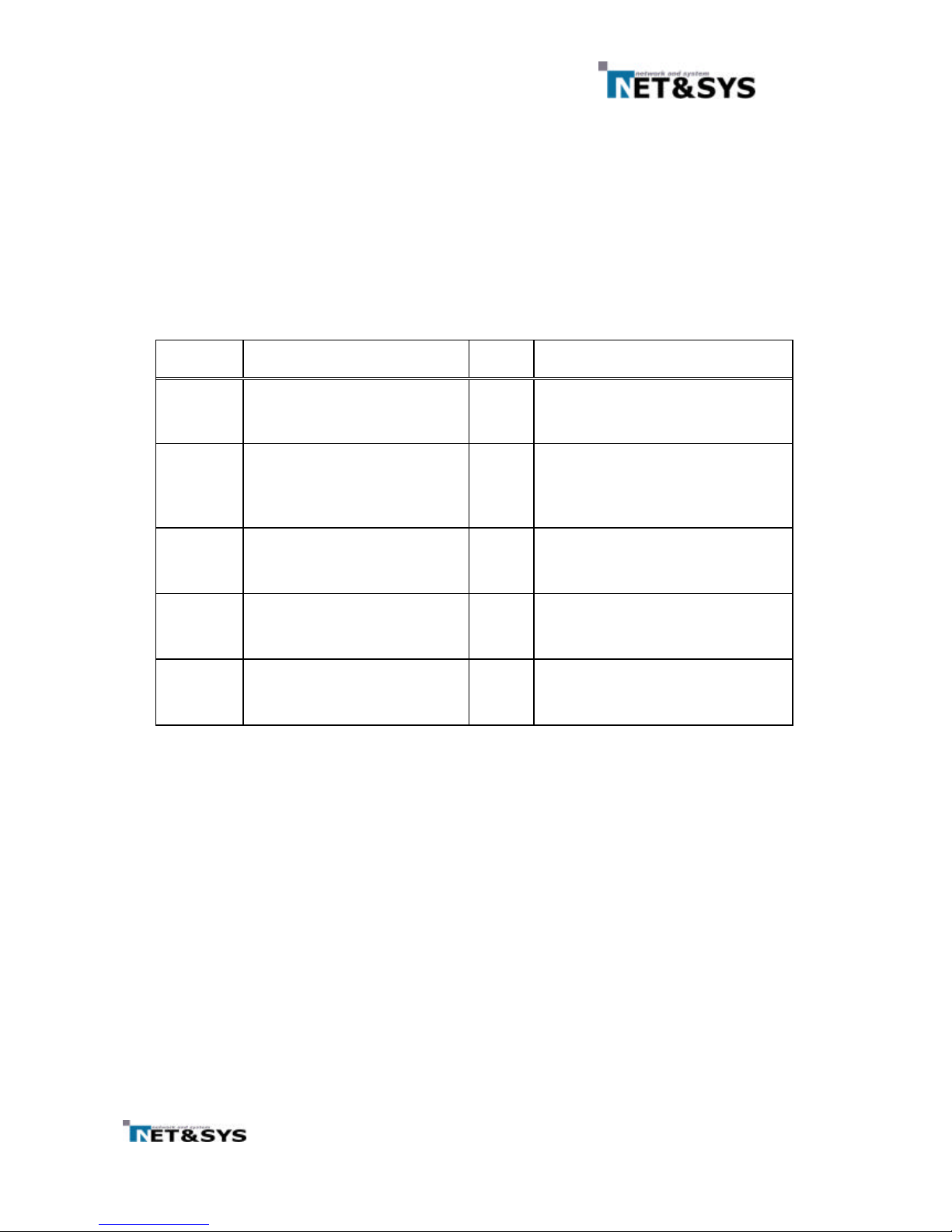
Table 1 LED Status Summary
LED Name
Function Color Status
POWER Power and program install Green
OFF: No power
STATUS
Modem and software
initialization status
Green
OFF: No power
FLASH : Normal progress
ON: Normal state
UP Cable port transmit status Green
OFF: No upstream channel
FLASH : Upstream data transfer
ON: Upstream channel sync
DOWN Cable port receive status Green
OFF: No downstream channel
FLASH : Downstream data transfer
ON: Downstream channel sync
LAN
Ethernet
transmit/receive
status
Green
OFF: Ethernet cable un-connected
FLASH :Data UP/DOWN in progress
ON: Ethernet link OK
Page 8
7
4 MNG-2000 Cable Modem Rear
The rear of the cable modem includes various connectors and switches. Some of the
connectors have been included to provide for additional functionality in the future and are not
currently being used.
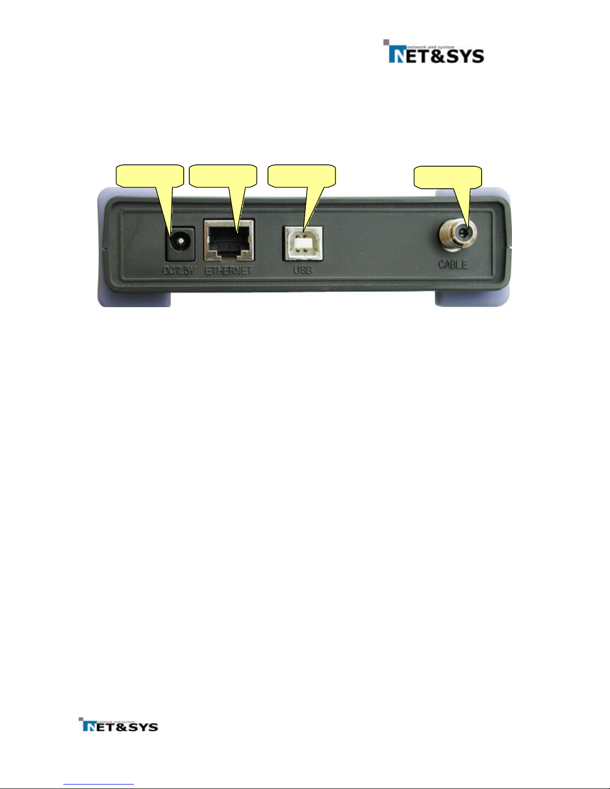
Figure 3 Cable Modem Rear View
4.1 DC in Connector
This connector is used to supply the DC power to the cable modem and is connected to the
plug from the 7.5V DC adaptor. The modem will undergo the initialization routine described in
chapter 3 upon power on.
Please do not use a DC power adaptor other than that included in the original box. Using an
unknown adaptor may cause a serious damage to the cable modem.
4.2 USB Connector
Currently Ethernet is used to connect the cable modem to the computer. Optionally USB may
be used instead. The current MNG-2000 operating program does not support USB by default. The
program supporting USB will be provided optionally and available for upgrade on the current
modem. In this case, the computer will not require the LAN card but it will need a software driver
which will be provided on a floppy disk.
4.3 Ethernet Connector
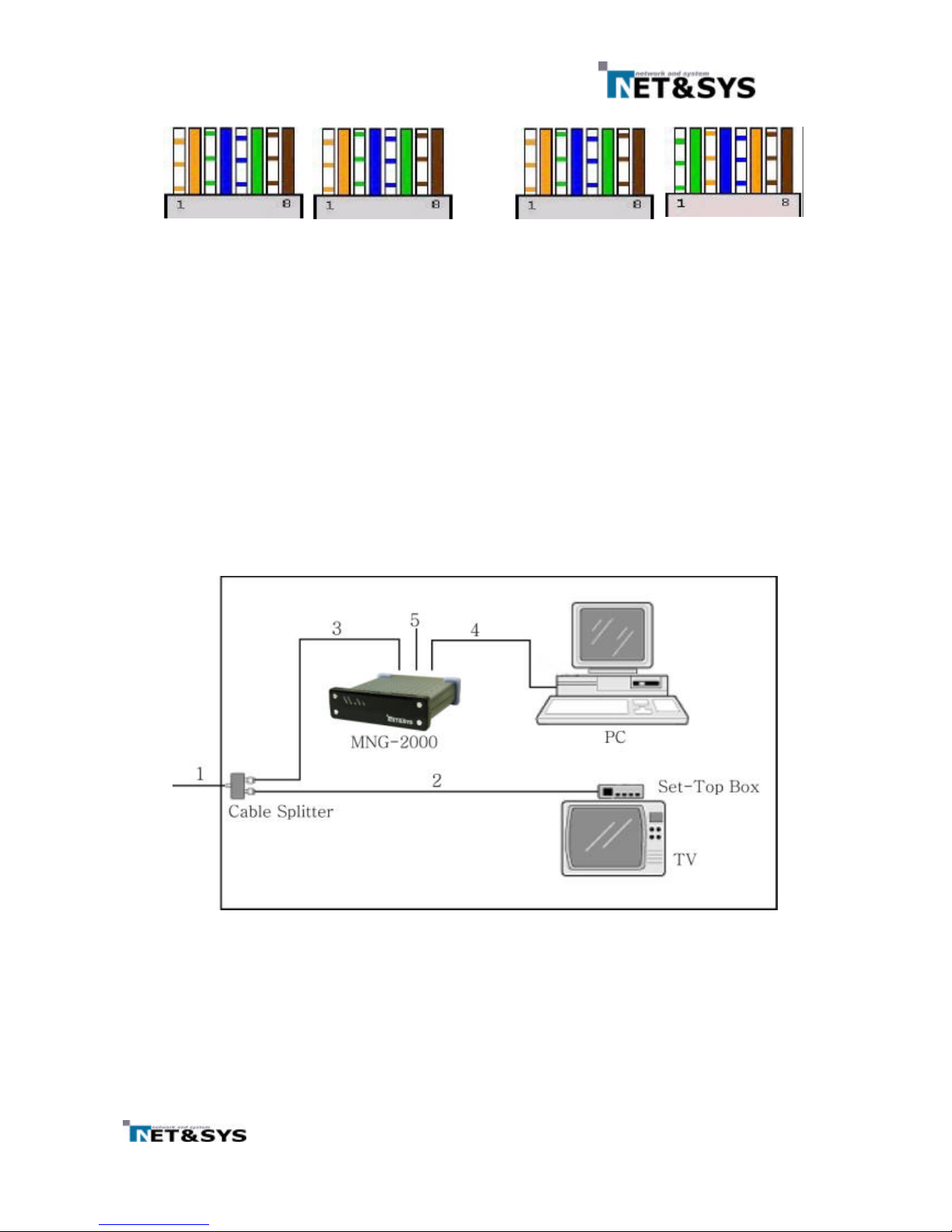
The MNG-2000 cable modem and computer can be linked using the Ethernet cable included in
the box. This cable is a “direct” connected cable.
There are two types of Ethernet cables, “direct” and “cross”. The “cross” type cable can be
used to connect the modem and hub. The diagram below is a enlargement of the Ethernet
connectors.
DC7.5V Ethernet USB
Cable
Page 9
8
Figure 4 Ethernet Cable Wiring Diagram
4.4 Cable Connector
The cable connector is used to connect the RF coaxial cable from the CATV network to the
modem. The cable modem is connected to the ISP via this connector.
5 Cable Modem Installation
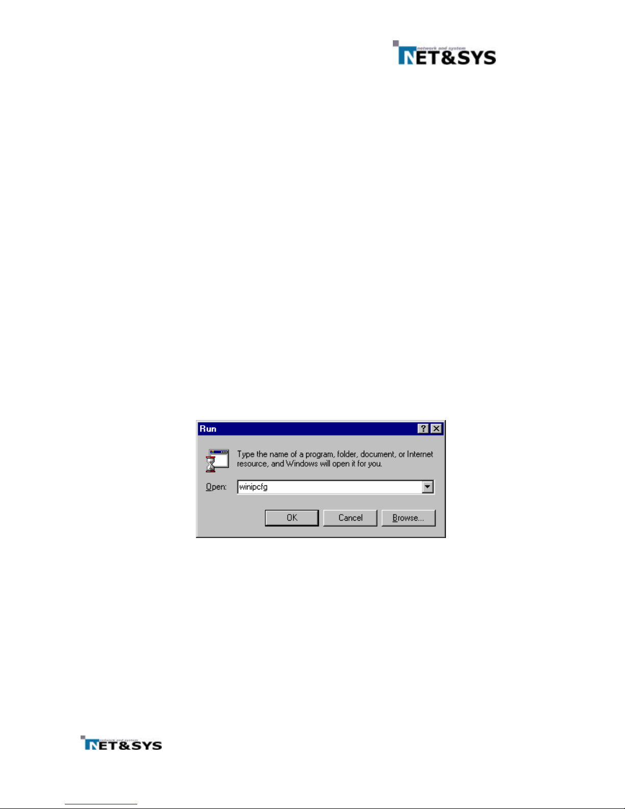
The figure below shows the rear of the MNG-2000 cable mo dem. The cable modem installation can
be setup as shown in figure 5.
Figure 5 Installation Setup
Direct Cross
Page 10
9
Each connector’s location is shown in Figure 3.
①
Connect the RF cable inside the home or office to the Cable connector.
②
Use the Ethernet cable included inside the box to connect the modem to the computer. The
computer must have a LAN installed with the proper LAN card driver installed on
Windows
95/98/NT/2000
③
Lastly, power up the modem by connecting the DC adaptor plug into the “DC in” jack of the modem.
You will be able to use your Internet within around 1.5 minuites.
m
If you are using USB optionally you have to install USB Network Driver at a PC. Refer Section 8.
After USB Network Driver at a PC is successfully installed, return back here and follow the next
procedure.
6 Cable Modem Inspection
In order to verify proper operation of the cable modem, the user must first inspect the LED status
and then verify that the computer as acquired IP correctly. The LED status is detailed in chapter 3.
6.1 Computer IP Address Verification
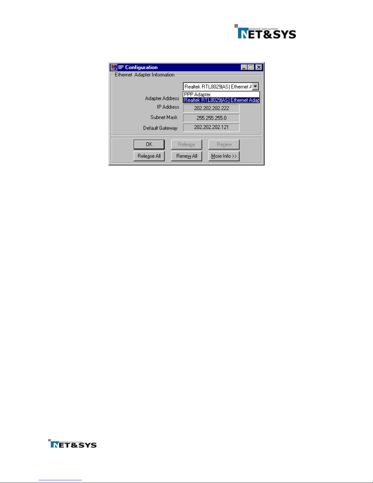
① Following proper operation of the cable modem based on LED indicators, the status of the
modem can be verified from the computer side as follows. From the desktop, select
[start]=>[run] and type “winipcfg”inside the popup window before clicking OK.
Figure 6 Run winipcfg program
Page 11
10
② From the IP Configuration popup window, select the correct Ethernet Adaptor.
Figure 7 Select Adaptor (LAN Card)
③ If the Ethernet adaptor’s IP is [0.0.0.0]
or
[169.X.X.X], the IP needs to be re-assigned for
proper Internet access. First, click [Release All] to release all previously assigned IP’s. The
IP Address should show either [0.0.0.0]
or
[169.X.X.X]. A new IP address will be assigned
after [Renew All] button is clicked.
④ If the IP does not change from [0.0.0.0]
or
[169.X.X.X] after the above procedure #3, there
are three possible reasons. Firstly, the cable modem may not be operating properly.
Secondly, LAN card may not be installed properly and thirdly, the server may be down.
⑤
In order to make sure that the cable modem may be the reason, it may be useful to unplug and then
re-connect the DC power from the modem and let it initialize again.
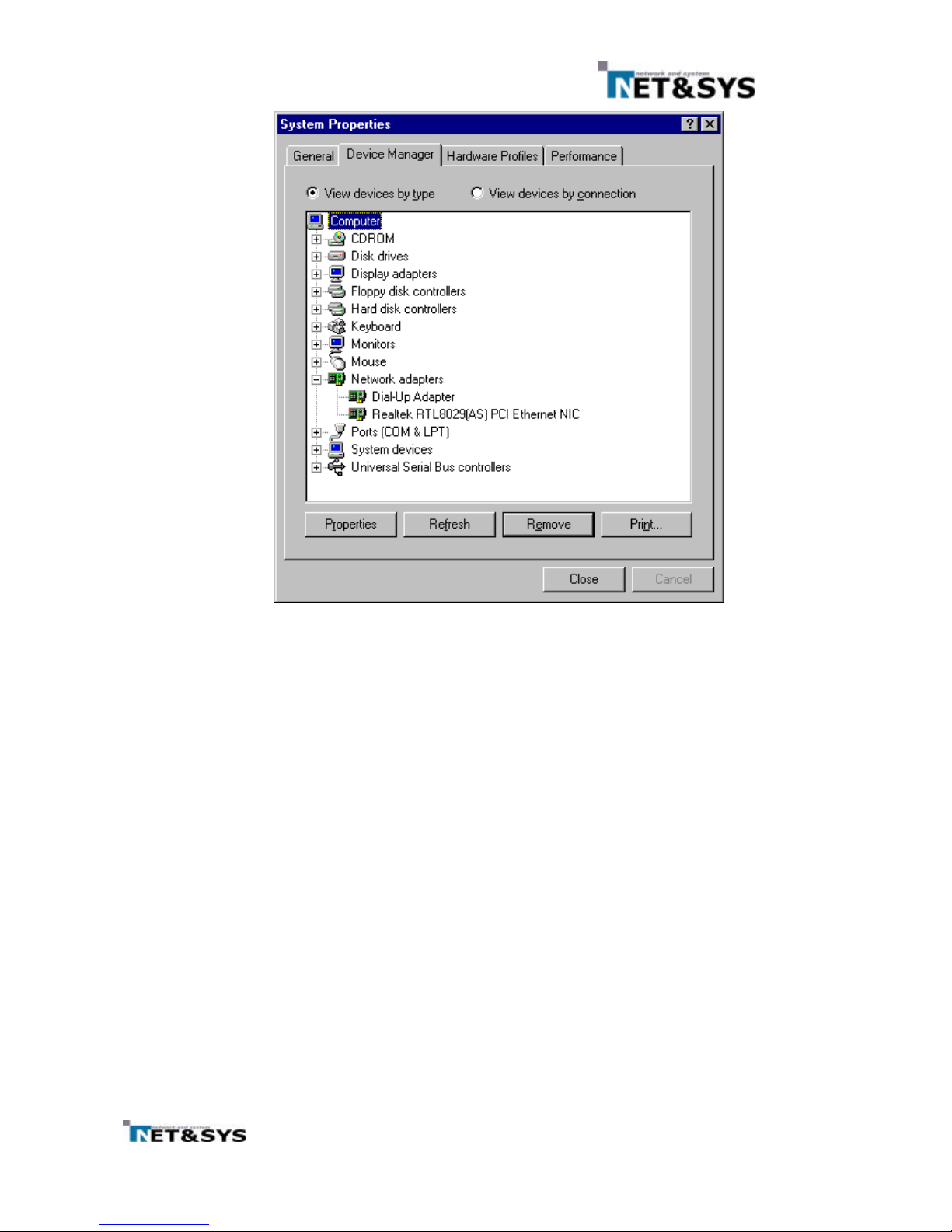
⑥ If the IP address is still not correct, select the menu [Start]=>[Settings]=>[Control
Panel]=>[System]=>[Device Manager]=>[Network Adaptors] and make sure that there is
no (!) in front of the LAN card. The (!) mark shows that the LAN card is not installed properly.
In this case, please try re-installing the LAN card after referring to the LAN card user’s
manual.
Page 12
11
Figure 8 Device Manager
⑦
If the IP address still cannot be acquired after procedures 5 & 6, please contact the
customer service center of your ISP.
6.2 Check Points for Modem Problems
① Please verify proper Ethernet connection between the modem and the computer.
If you are using UBS, please verify USB connection between the modem and the computer.
②
Please verify that the RF cable is properly connected to the cable modem.
③
Please verify proper installation of the computer OS, TCP/IP protocol and LAN card.
④ Please verify that the cable modem information(MAC address) is properly registered with
the ISP.
⑤
If the problem remains unresolved, please refer to this manual again or contact the
purchase company or store.
Page 13
12
7 USB Network Driver Installation Guide
7.1 Install NetnSys Cable Modem USB Network Driver under Windows 98 and
98SE for the First Time
The Installation of NetnSys Cable Modem USB Network Driver under Windows Me is similar to
that of the cable modem USB Network driver under Windows 98 and 98SE
7.1.1 Install NetnSys Cable Modem USB Network Driver
① Turn on the cable modem, computer and start Windows
② Connect one end of the USB cable to cable modem and the other end to one of the computer’s
USB Port.
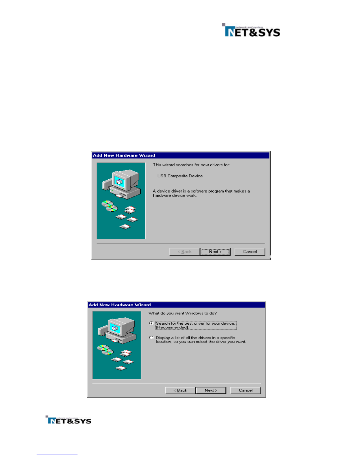
③ Windows detects that new hardware has been added and start the Add New Hardware Wizard,
See Figure 9.
④ Click Next
Figure 9 Add New Hardware Wizard for windows 9x (Screen 1)
⑤ The wizard asks, “What do you want windows to do ?”. see Figure 10. Choose “Search for the
best driver for your device ”.
⑥ Click Next.
Figure 10
Add New Hardware Wizard for windows 98 (Screen 2)
Page 14
13
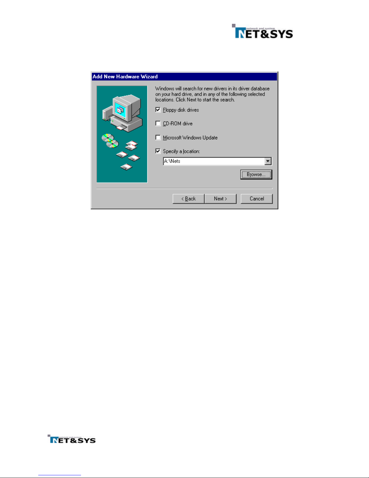
⑦ Specify the location of the driver. See Figure 11. If installing the driver disk into the disk drive
and select the Floppy disk drive check box. Otherwise, select the Specify a location and the
path where the driver files can be found
⑧ Click Next
Figure 11
Selecting for the driver
Page 15
14
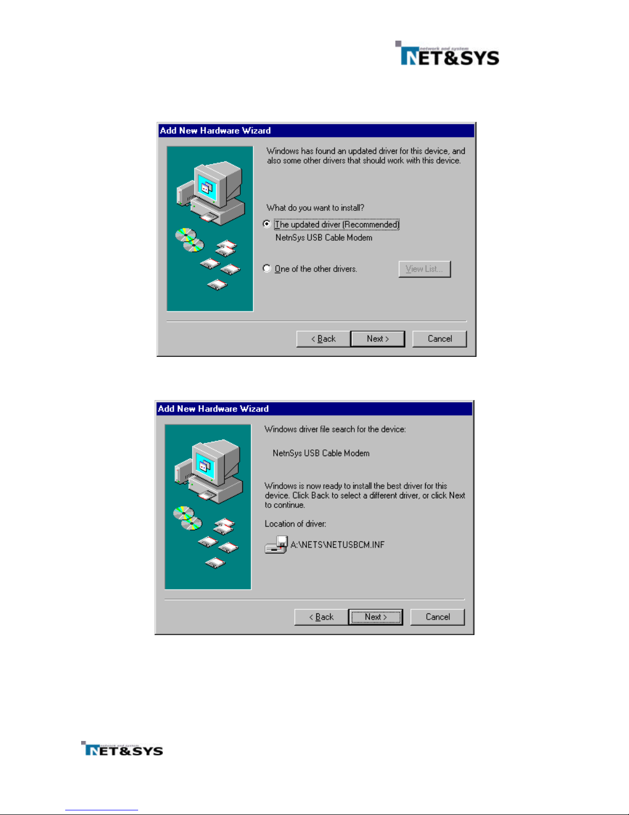
⑨ The wizard searches for the driver and finds the NetnSys USB Cable Modem Driver; see Figure
12 and Figure 13.
⑩ Click Next.
Figure 12
Driver Found (Screen 1)
Figure 13
Driver Found (Screen 2)
Page 16
15
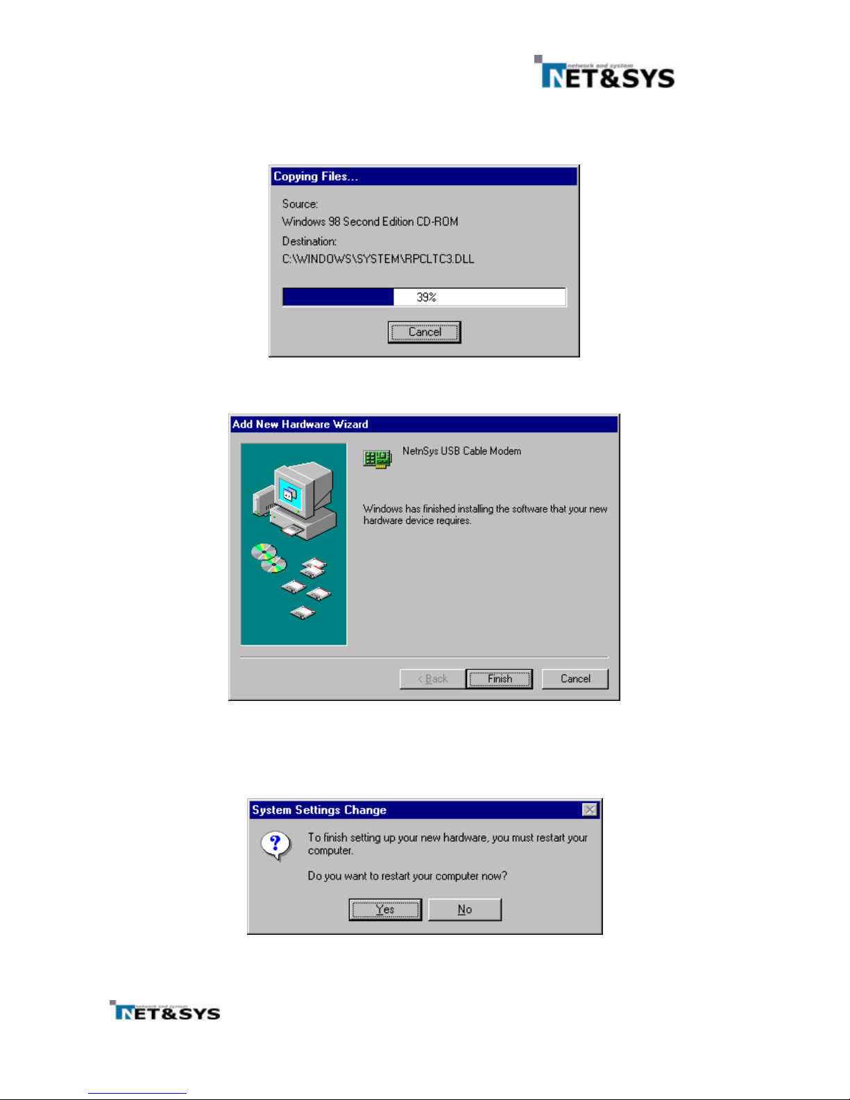
⑪ After the initial setup files are copied, the wizard indicates it has completed the driver
installation, see Figure 15.
⑫ Click Finish
Figure 14
Copying Files
Figure 15
Installation Complete
⑬ A dialog box prompts you to restart your computer; see Figure 16. Click Yes
Figure 16
Reboot Prompt Dialog Box
Page 17
16
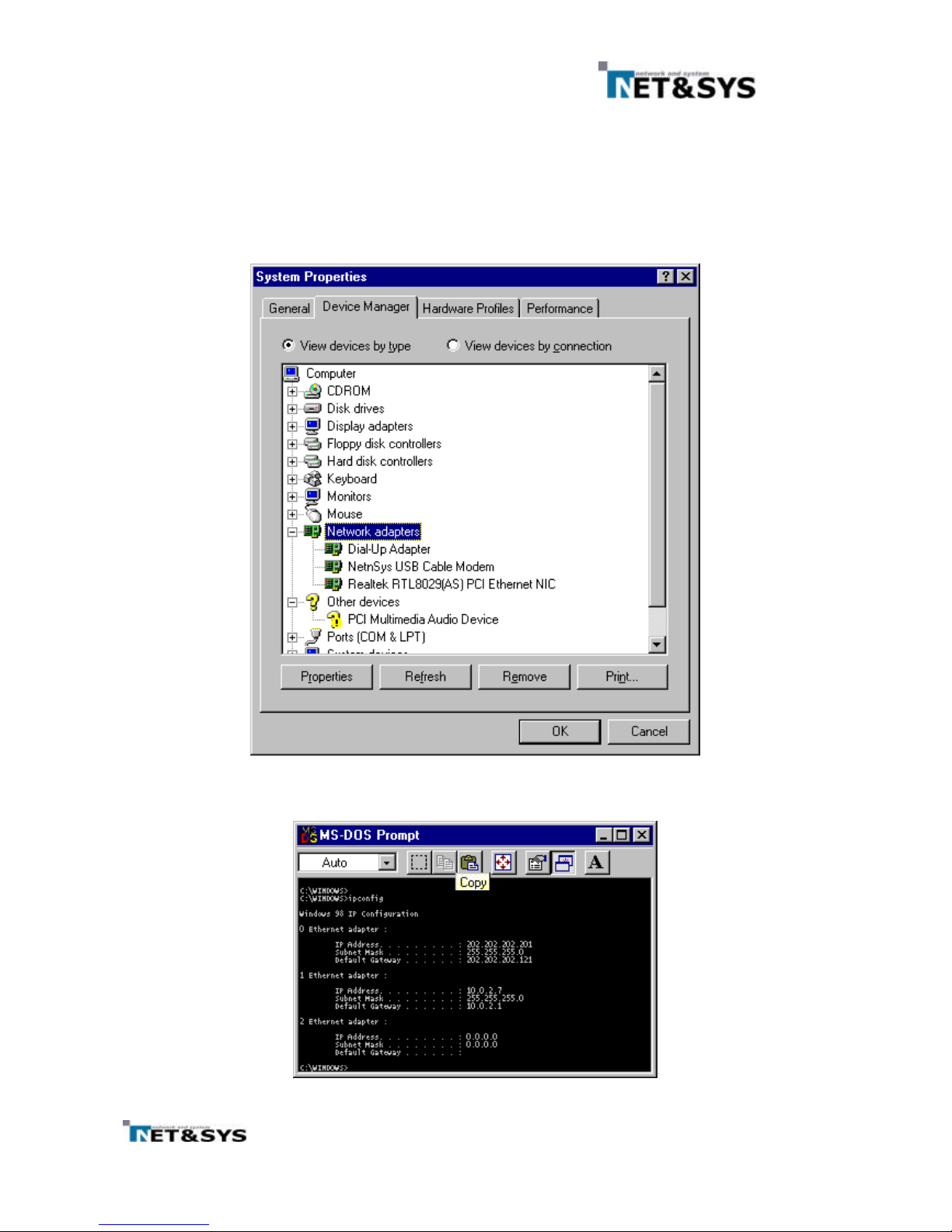
7.1.2 Verifying Driver Installation
• From the Start menu, point to Settings and click Control Panel
‚ Double click Network
ƒ The Network Control Panel Applet appears; See Figure 17. Verify the NetnSys USB Cable
Modem Driver is present. If needed, you can verify the presence of the USB Cable Modem Driver
from the DOS prompt by using the “ipconfig” command; see Figure 18.
Figure 17
Network Neighborhood Property
Figure 18
“Ipconfig” Command
Page 18
17
7.2 Install NetnSys Cable Modem USB Network Driver under Windows 2000 for
the First Time
7.2.1 Install NetnSys Cable Modem USB Network Driver
① Turn on the cable modem, computer and start Windows
② Connect one end of the USB cable to cable modem and the other end to one of the computer’s
USB Port.
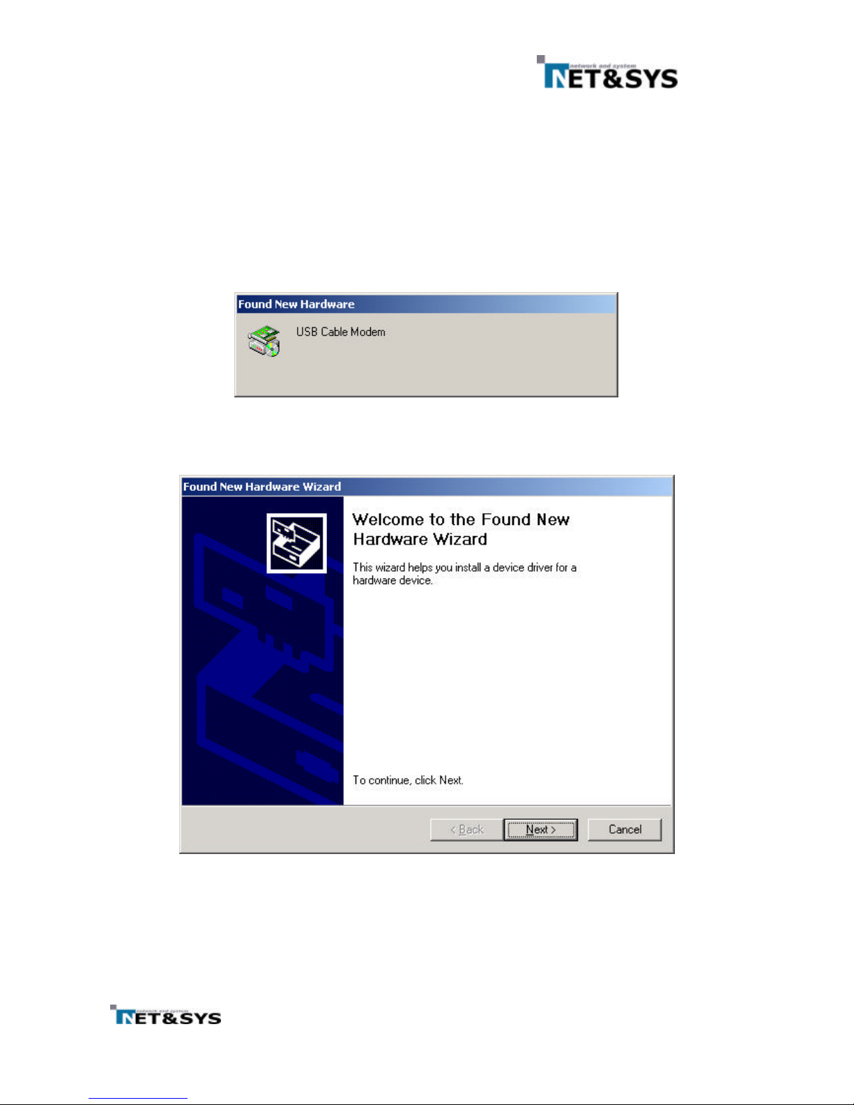
③ Windows detects that new hardware has been added and start the Add New Hardware Wizard,
See Figure 19 and Figure 20. Click Next
Figure 19
Added New Hardware Wizard for Windows 2000
Figure 20
Found New Hardware Wizard for Windows 2000
Page 19
18
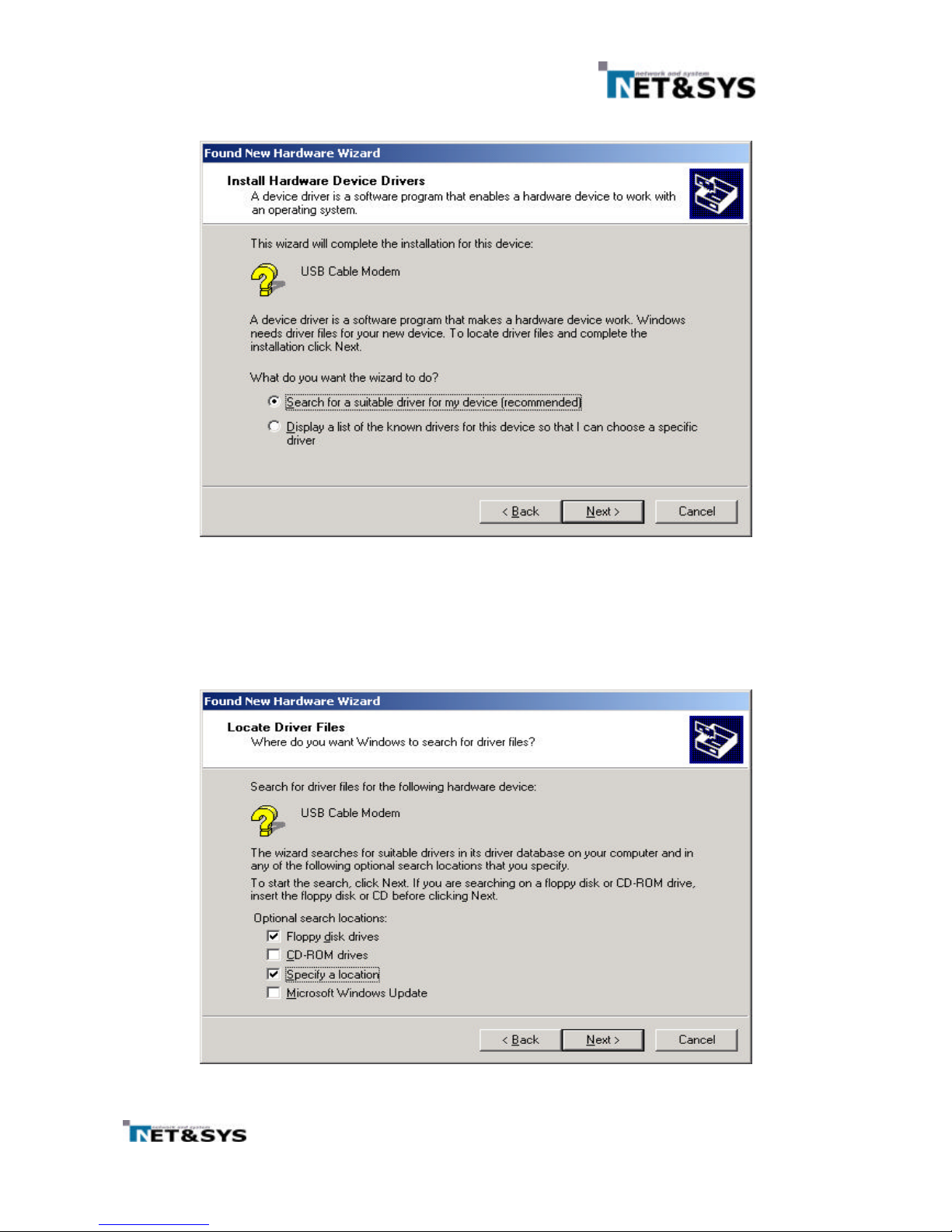
④ The Wizard asks “What do you want to do ?” See Figure 21. Choose “Search for a suitable for
my device ” and click Next.
Figure 21
Searching for driver (Screen 1)
⑤ Select the location of the driver; see Figure 22. If installing from a floppy, insert the driver disk
into the disk driver and select Floppy disk drives check box. Otherwise select the Specify a
location checkbox and the path where the driver file can be found.
Figure 22
Searching for a Driver (Screen 2)
Page 20
19
⑥
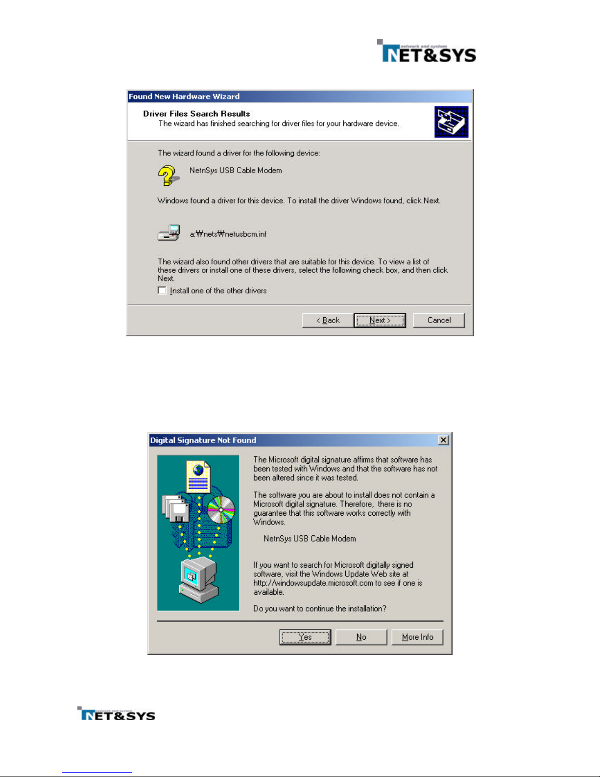
The file netusbcm.inf is the correct driver; see Figure 23 and click next
Figure 23
Driver Search Results
⑦ A digital signature is provided by Microsoft upon completion of the WHQL(Windows Hardware
Quality Lab) certification process. As Net & Sys does not submit this USB driver hardware for
WHQL certification, no Digital Signature is provided (See Figure 25.) Click Yes.
Figure 24
Digital Signature Not Found
Page 21
20
⑧
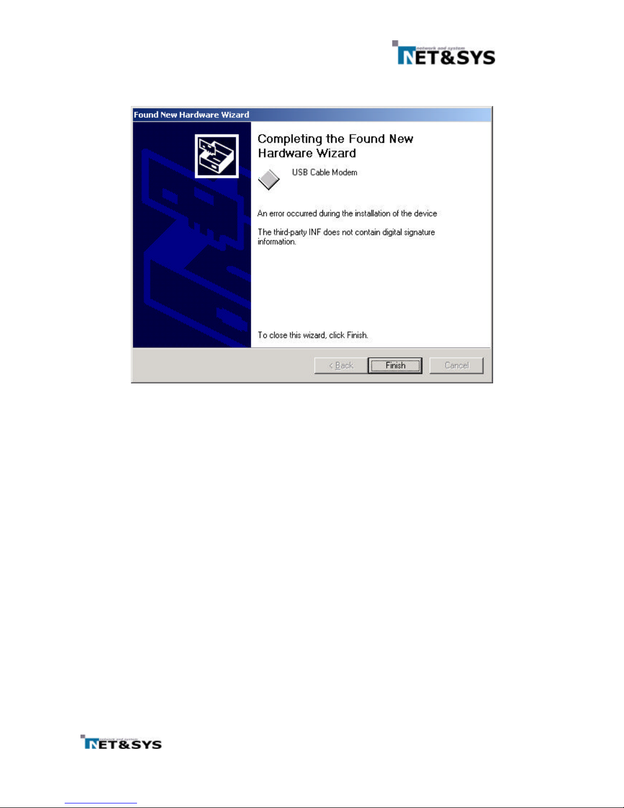
When the driver installation program is complete, the Completing the Found New Hardware
Wizard window appears; see Figure 25. Click Finish.
Figure 25
Notification Screen
Page 22
21
7.2.2 Verifying Driver Installation
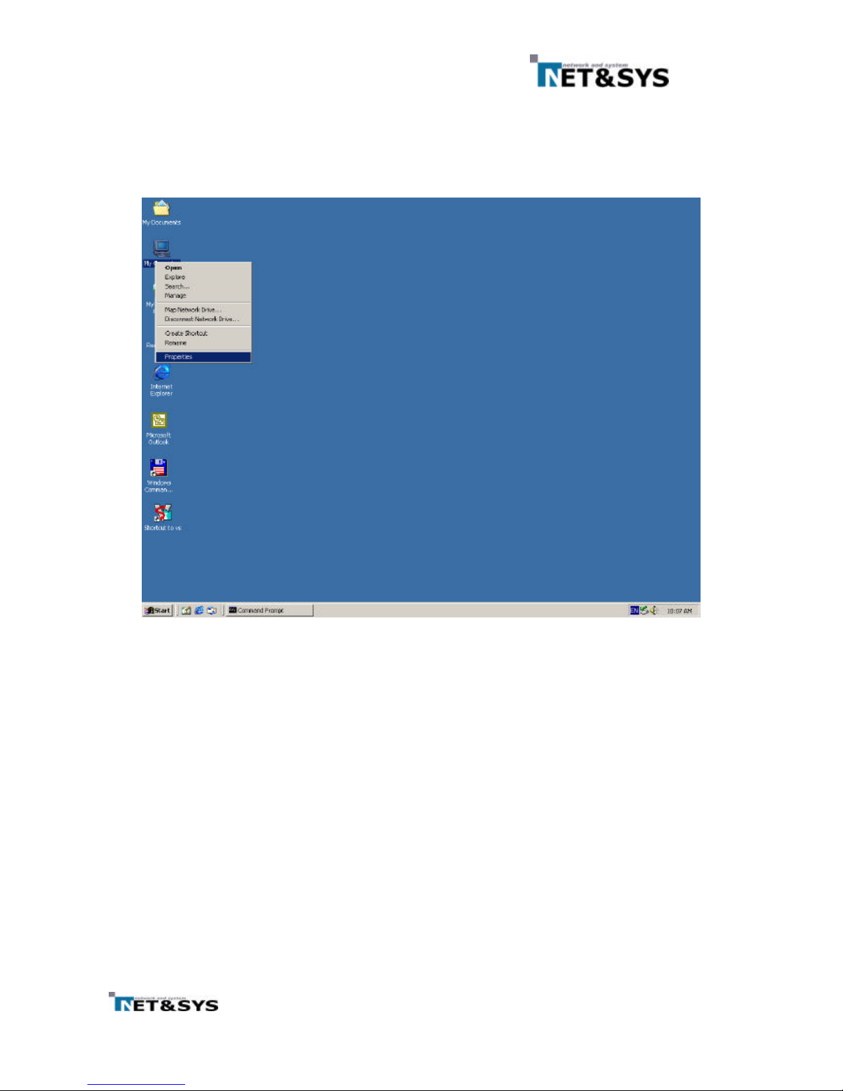
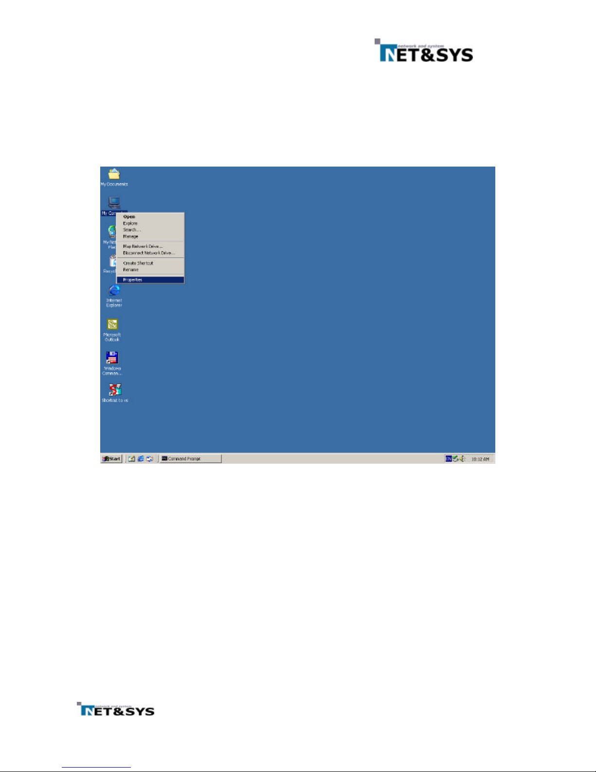
① To verify that USB driver has been properly installed, Do the following from the windows
desktop. See Figure 26.
② Right-Click the My Computer icon and click the properties.
Figure 26
Windows Desktop
Page 23
22
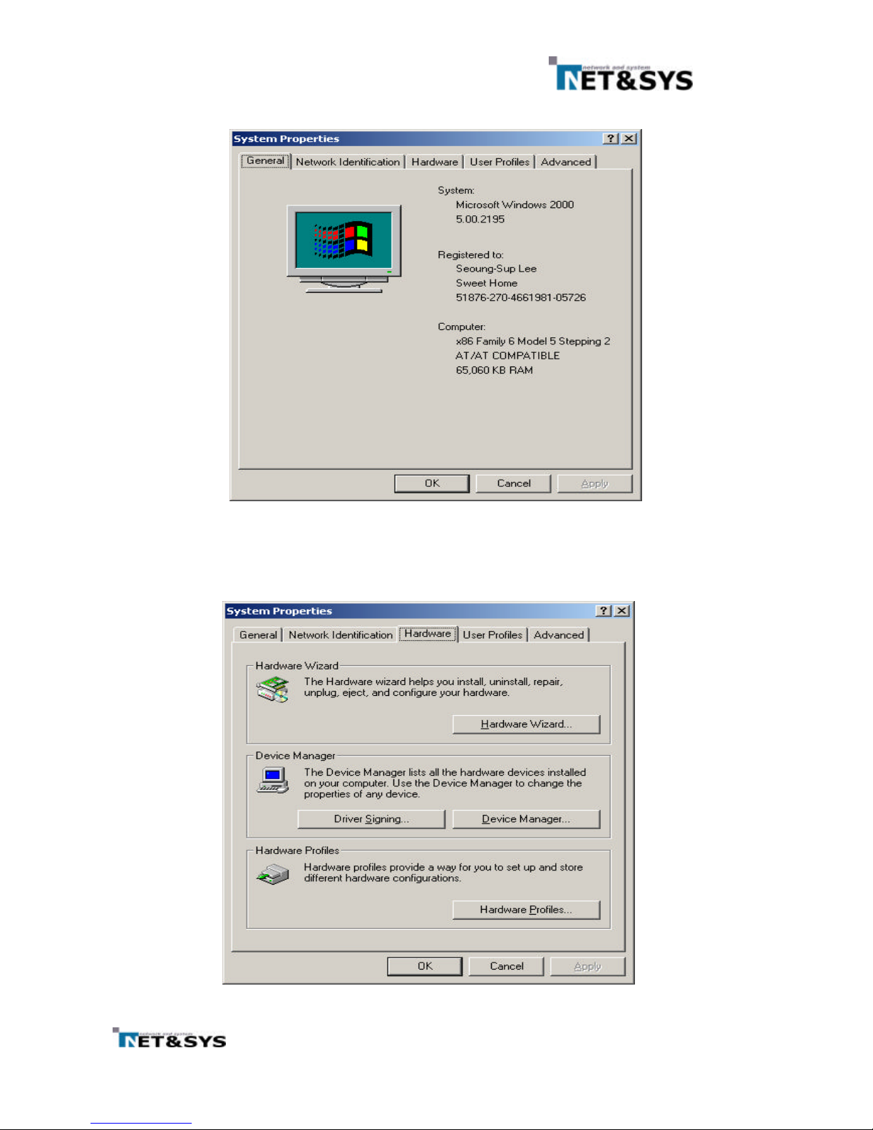
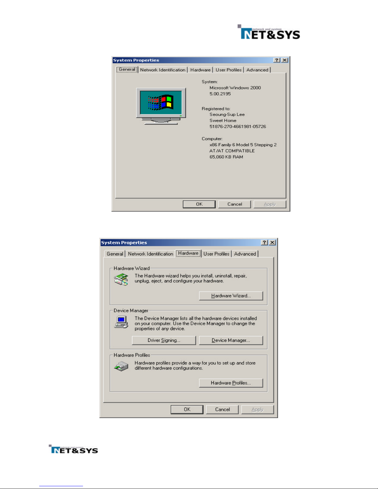
③ The system properties appears; see Figure 27. Click the hardware tab
Figure 27
System Properties
④
The Hardware Properties appears; see Figure 28. Click Device Manager
Figure 28
Hardware Properties
Page 24
23
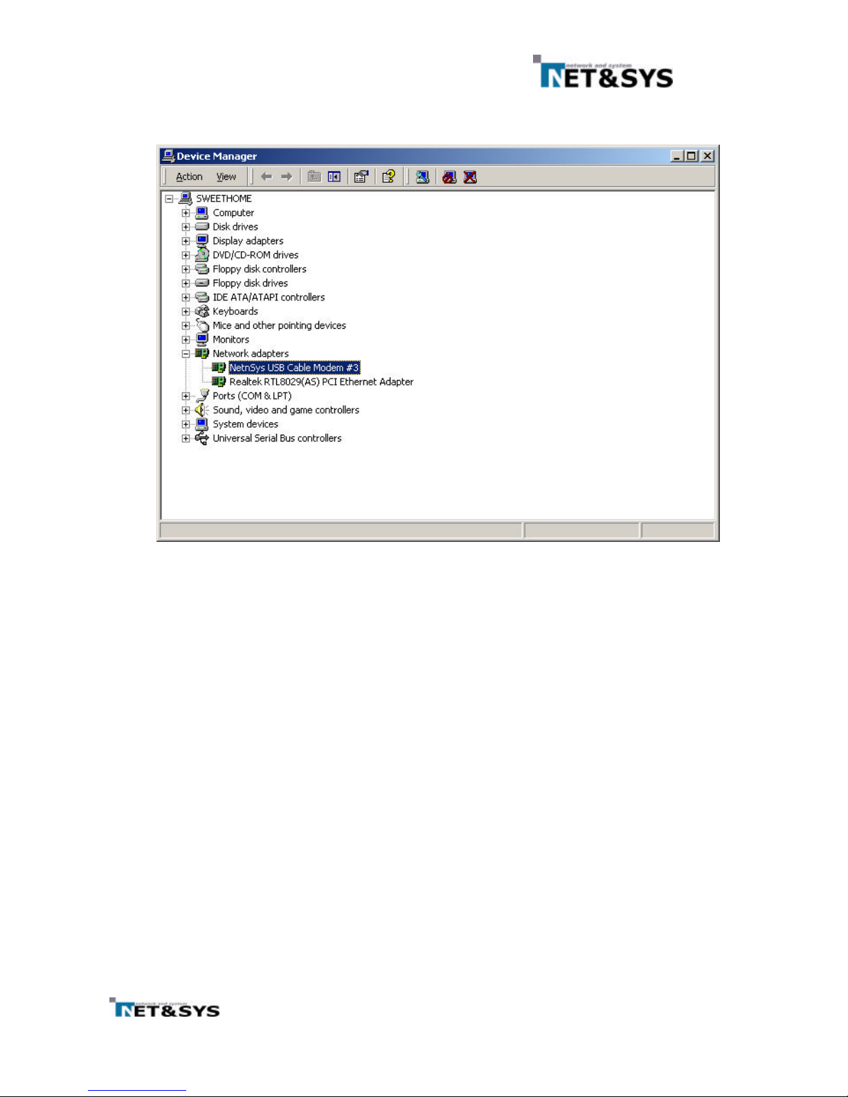
⑤ The Device Manager windows is displayed; see Figure 29.
⑥ Verify the driver installation by expanding Network Adaptors
Figure 29
Device Manager
Page 25
24
7.2.3 Uninstalling the driver
① To verify that USB driver has been properly installed, Do the following from the windows
desktop. See Figure 30.
② Right-Click the My Computer icon and click the properties.
Figure 30
Windows Desktop
Page 26
25
③ The syst em properties appears; see Figure 31. Click the hardware tab
Figure 31
System Properties
④
The Hardware Properties appears; see Figure 32. Click Device Manager
Figure 32
Device Manager
Page 27
26
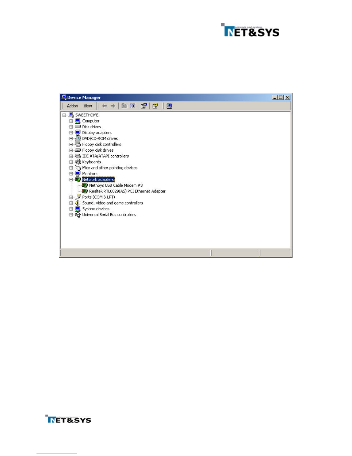
⑤ The Device Manager windows is displayed; see Figure 33.
⑥ Expend Network Adaptors and highlight “NetnSys USB Cable Modem”
⑦ Select Remove from Action Menu.
⑧ A warning message is displayed stating that the driver is about to be removed. Click OK and
restart the computer.
Figure 33
Device Manager
Page 28

27
8 Contact Information
Sales Contact
E-mail: sales@ netnsys.com
Web Page
Http//:www.netnsys.com
 Loading...