

Page 1

NetSure™ 7100 DC Power System
1
System Application Guide
SYSTEM OVERVIEW
Description: -48 VDC @ up to 12000 Amperes Power System
The NetSure 7100 DC Power System is an integrated power system containing -48 VDC rectifiers or
converters, optional +24 VDC converters, intelligent control, metering, monitoring, and distribution.
This power system is designed to power a load while charging a positive grounded battery. This power
system is capable of operating in a batteryless installation or off battery for maintenance purposes. The
power system is designed for operation with the positive output grounded.
This system consists of the following components.
Distribution Cabinet
•
The system always includes a minimum of one distribution cabinet, which provides DC distribution
through fuses and/or circuit breakers. The distribution cabinet is factory mounted in a relay rack, on
shipping brackets, or in an enclosure as specified when ordered.
Four different sizes of distribution cabinets are available to accept from one (1) to four (4) distribution
panels. A variety of distribution panels are available that provide load distribution, battery
distribution, and dual voltage load distribution for use with +24 VDC converters. These distribution
panels are configured to accept either bullet nose type circuit breakers and TPS/TLS fuseholders,
TPH fuses, TPL-B fuses, or GJ/218 circuit breakers. A bulk output panel is also available.
The distribution cabinet may be equipped with low voltage load disconnect (LVLD), low voltage
battery disconnect (LVBD), and manual battery disconnect.
Controller
•
NCU (NetSure Control Unit): The controller provides power system control (including optional low
voltage battery disconnect (LVBD) and low voltage load disconnect (LVLD) control), rectifier control
(including a charge control function), converter control, metering functions, monitoring functions, and
local/remote alarm functions. The controller also supports rectifier temperature compensation if the
system is equipped with a temperature probe(s). Temperature probe(s) may also be designated to
monitor ambient temperature and/or battery temperature. The controller also provides data
acquisition, system alarm management, and advanced battery and energy management. The
controller contains a color LCD display and keypad for local access. The controller provides an
Ethernet port and comes with comprehensive webpages for remote access. The controller has SNMP
v3 capability for remote system management. The controller supports software upgrade via its USB
port. Refer to the NCU Controller Instructions (UM1M830BNA) for more information.
Module Mounting Assembly (Spec. No. 588705000)
•
The system may contain one or more Spec. No. 588705000 module mounting assemblies, each of
which houses up to six (6) 3500 watt rectifier modules or six (6) 3500 watt converter modules.
o
Rectifier Modules (for use in Spec. No. 588705000)
The system may contain 3500 watt rectifier modules; which provide load power, battery float
current, and battery recharge current during normal operating conditions. Refer to the Rectifier
Instructions (UM1R483500e) for more information.
Converter Modules (for use in Spec. No. 588705000)
o
The system may contain 3500 watt converter modules; which provide load power, battery float
current, and battery recharge current during normal operating conditions. Refer to the Converter
Instructions (UM1C400483500e) for more information.
Module Mounting Assembly (Spec. No. 588705300)
•
The system may contain one or more Spec. No. 588705300 module mounting assemblies, each of
which houses 2000 watt rectifier modules and optional +24 VDC, 1500 watt DC-DC converter
modules.
Rectifier Modules (for use in Spec. No. 588705300)
o
The system contains 2000 watt rectifier modules; which provide load power, battery float current,
and battery recharge current during normal operating conditions. Refer to the Rectifier
Instructions (UM1R482000e3) for more information.
Optional DC-DC Converter Modules (for use in Spec. No. 588705300)
o
Where +24 VDC load power is also required, 1500 watt DC-DC converter modules are available.
Refer to the Converter Instructions (UM1C48241500) for more information.
Spec. No: 582127000 SAG582127000
Model No: 7100 Revision BJ, August 21, 2020
Page 2
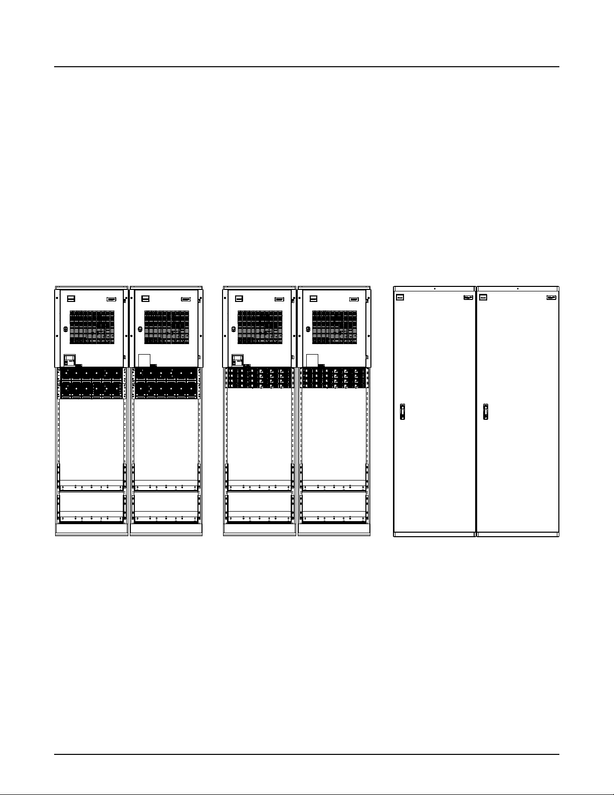
NetSure™ 7100 DC Power System
2
(E/W Spec. No. 588705000
or 588705500 Module
Mounting Assemblies)
(E/W Spec. No. 588705300
or 588705400 Module
Mounting Assemblies)
(Installed in an Enclosure)
Main Bay Supplemental Bay Main Bay
Enclosure
Supplemental Bay
Enclosure
Main Bay Supplemental Bay
System Application Guide
• Module Mounting Assembly (Spec. No. 588705400)
The system may contain one or more Spec. No. 588705400 module mounting assemblies, each of
which houses up to six (6) 3500 watt rectifier modules.
o
Rectifier Modules (for use in Spec. No. 588705400)
The system contains 3500 watt rectifier modules; which provide load power, battery float current,
and battery recharge current during normal operating conditions. Refer to the Rectifier
Instructions (UM1R483500e3) for more information.
Module Mounting Assembly (Spec. No. 588705500)
•
The system may contain one or more Spec. No. 588705500 module mounting assemblies, each of
which houses up to six (6) 4000 watt rectifier modules.
o
Rectifier Modules (for use in Spec. No. 588705500)
The system contains 4000 watt rectifier modules; which provide load power, battery float current,
and battery recharge current during normal operating conditions. Refer to the Rectifier
Instructions (UM1R483500e) for more information.
Spec. No: 582127000 SAG582127000
Model No: 7100 Revision BJ, August 21, 2020
Page 3

NetSure™ 7100 DC Power System
3
System Application Guide
General Specifications
See detailed specifications on page 228.
Family: NetSure
System Spec. No.: 582127000
System Model: 7100
System AC Input Voltage: 582127000 List 40, 41: Nominal 208 VAC, 240 VAC, 277 VAC, single phase, 50 Hz /
582127000 List 42: Nominal 208 VAC, 240 VAC, three-phase (3L+PE), 50 Hz / 60
582127000 List 43: Nominal 277/480 VAC, three-phase (3L+N+PE), 50 Hz / 60 Hz,
582127000 List 100, 101, 102, 103, 203: Nominal 208 VAC, 240 VAC, single phase,
System DC Input Voltage: 582127000 List 45, 46, 47: Input voltage range of 260 VDC to 400 VDC (when used
System Output Capacity:
System: 12000 A maximum distribution and battery charge/discharge capacity, 12000 A
Bay: 2000 A maximum distribution and battery charge/discharge capacity, 2500 A
Distribution Panel: Refer to the individual distribution panels list descriptions under “List Descriptions
1R482000e3 Rectifier Rating: See UM1R482000e3.
1R483500e Rectifier Rating: See UM1R483500e.
1R483500e3 Rectifier Rating: See UM1R483500e3.
1R484000e Rectifier Rating: See UM1R483500e.
1C400483500e Converter Rating: See UM1C400483500e.
1C48241500 Converter Rating: See UM1C48241500.
System Agency Approval: UL 1801 Listed (“c UL”), NEBS
60 Hz, with an operating range of 176 VAC to 305 VAC. Acceptable input
frequency range is 45 Hz to 65 Hz.
Hz, with an operating range of 176 VAC to 275 VAC. Acceptable input frequency
range is 45 Hz to 65 Hz.
with an operating range of 176/305 VAC to 305/528 VAC. Acceptable input
frequency range is 45 Hz to 65 Hz. (For use with 588705000, 588705400, and
588705500 module mounting assemblies.)
50 Hz / 60 Hz, with an operating range of 176 VAC to 275 VAC. Acceptable input
frequency range is 45 Hz to 65 Hz.
with 588705000).
maximum rectifier capacity
maximum rectifier capacity (when used with 588705000, 588705400, or
588705500 shelves)
1500 A @ -48 VDC and 520 A @ +24 VDC, maximum (when used with 588705300,
except List 100, 101, 102, 103, 203)
1000 A @ -48 VDC and 500 A @ +24 VDC, maximum (when used with List 100, 101,
102, 103, 203)
(582127000)” starting on page 24.
Spec. No: 582127000 SAG582127000
Model No: 7100 Revision BJ, August 21, 2020
Page 4

NetSure™ 7100 DC Power System
4
System Application Guide
Relay Rack Version:
Framework Type: Relay Rack
Mounting Width: 23 Inches, nominal
Mounting Depth:
Distribution Cabinet: 20.09 Inches
Module
Mounting Assembly: 20.09 Inches
Battery Tray: 22.5 Inches
Enclosure Version:
Framework Type: Enclosure
Enclosure Width: 28 Inches
Enclosure Depth: 28 Inches
Enclosure Height: 84 Inches
Access: Front for installation, operation, and maintenance. Rear for supplemental bay
Supplemental Bay(s) Available: Six (6)
Control: Microprocessor
Color: Enclosure: Textured Dark Gray (P/N 563524) or Textured White (P/N 564881)
Environment: -40 °C to +40 °C (-40 °F to +104 °F)
expansion, rectifier shelf expansion and battery tray installation.
Distribution Cabinet, Relay Racks and Module Faceplates: Dark Gray
Module Mounting Assembly and Module Bodies: Bright Zinc Plating
Spec. No: 582127000 SAG582127000
Model No: 7100 Revision BJ, August 21, 2020
Page 5

NetSure™ 7100 DC Power System
5
System Application Guide
TABLE OF CONTENTS
SYSTEM OVERVIEW ....................................................................................................................................................................................................... 1
MAIN COMPONENTS ILLUSTRATIONS ................................................................................................................................................................. 13
582127000 (Relay Rack) ...................................................................................................................................................................................... 13
582127000 (Relay Rack) ...................................................................................................................................................................................... 14
582127000 (Relay Rack) ...................................................................................................................................................................................... 15
582127000 (Relay Rack) ...................................................................................................................................................................................... 16
582127000 List 100 (Relay Rack) ...................................................................................................................................................................... 17
582127000 List 101 (Relay Rack) ....................................................................................................................................................................... 18
582127000 List 102 (Relay Rack) ...................................................................................................................................................................... 19
582127000 List 103 (Relay Rack) ..................................................................................................................................................................... 20
582127000 List 203 (Relay Rack) ..................................................................................................................................................................... 21
582127000 (Enclosure) ........................................................................................................................................................................................ 22
582127000 (Enclosure) ........................................................................................................................................................................................ 23
LIST DESCRIPTIONS (582127000) ......................................................................................................................................................................... 24
List Numbers (582127000) ................................................................................................................................................................................ 24
List 1: Main Bay Common Equipment (Power and Distribution), For System Mounted in a Relay Rack, on Shipping
Rails, or in an Enclosure ...................................................................................................................................................................................................................... 24
List 2: 1st Supplemental Bay Common Equipment (Power and Distribution or Distribution Only), Located In-Line
with Main Bay, For System Mounted in a Relay Rack Only ............................................................................................................................................. 26
List 3: 3rd through 6th Supplemental Bays Common Equipment (Power and Distribution or Distribution Only),
Located In-Line with Main Bay, For System Mounted in a Relay Rack Only ......................................................................................................... 27
List 4: Distribution Only Bay Distribution Cabinet Bottom Rear Cover .................................................................................................................. 29
List 5: 2nd through 6th Supplemental Bay Common Equipment (Power and Distribution or Distribution Only),
Located Remote from Main Bay ..................................................................................................................................................................................................... 29
List 7: 1st Supplemental Bay Common Equipment (Power and Distribution or Distribution Only), Located In-Line
with Main Bay, Enclosure Mounted Option Only .................................................................................................................................................................... 31
List 8: 3rd through 6th Supplemental Bay Common Equipment (Power and Distribution or Distribution Only),
Located In-Line with Main Bay, Enclosure Mounted Option Only .............................................................................................................................. 33
List 21: One-Row Distribution Cabinet, For System Mounted in a Relay Rack or on Shipping Rails Only ........................................... 35
List 22: Two-Row Distribution Cabinet, For System Mounted in a Relay Rack or on Shipping Rails Only ......................................... 35
List 23: Three-Row Distribution Cabinet, For System Mounted in a Relay Rack, on Shipping Rails, or in an
Enclosure ..................................................................................................................................................................................................................................................... 36
List 24: Four-Row Distribution Cabinet, For System Mounted in a Relay Rack, on Shipping Rails, or in an Enclosure ............... 36
List 28: DC Conduit Box, For System Mounted in a Relay Rack Only ...................................................................................................................... 37
List 29: Top Shield for Distribution Cabinet, For System Mounted in a Relay Rack Only ............................................................................ 37
List 30: Module Mounting Assembly Interface Components (for Spec. No. 58870500021, 58870500022,
58870500031, 58870500032, 58870500033) ........................................................................................................................................................................ 38
List 31: Module Mounting Assembly Field Expansion Kit (for Spec. No. 58870500022, 58870500031,
58870500032, 58870500033), For System Mounted in a Relay Rack or Enclosure ........................................................................................ 38
List 32: Module Mounting Assembly Interface Components (for Spec. No. 588705300), For System Mounted in a
Relay Rack or on Shipping Rails Only .......................................................................................................................................................................................... 39
List 33: Module Mounting Assembly Field Expansion Kit (for Spec. No. 58870530003), For System Mounted in a
Relay Rack or on Shipping Rails Only .......................................................................................................................................................................................... 39
List 34: Module Mounting Assembly Interface Components (for Spec. No. 58870500040, 58870500041,
58870500042), For System Mounted in a Relay Rack or on Shipping Rails Only ............................................................................................ 40
List 35: Module Mounting Assembly Field Expansion Kit (for Spec. No. 58870500041, 58870500042), For System
Mounted in a Relay Rack or on Shipping Rails Only .......................................................................................................................................................... 40
List 36: Module Mounting Assembly Interface Components (for Spec. No. 588705400) ............................................................................ 41
List 37: Module Mounting Assembly Field Expansion Kit (for Spec. No. 588705400) ................................................................................... 41
List 38: Module Mounting Assembly Interface Components (for Spec. No. 58870550001, 58870550002,
58870550003, 58870550004, 58870550005) ....................................................................................................................................................................... 42
List 39: Module Mounting Assembly Field Expansion Kit (for Spec. No. 58870550002, 58870550003,
58870550004, 58870550005), For System Mounted in a Relay Rack or Enclosure ........................................................................................ 42
List 40: Front Access AC Input Termination Assembly (1 AC Feed per 1 Rectifier, Single Phase) ......................................................... 43
List 41: Front Access AC Input Termination Assembly (1 AC Feed per 2 Rectifiers, Single Phase) ....................................................... 43
List 42: Front Access AC Input Termination Assembly (1 AC Feed per 3 Rectifiers, 3-Phase) ................................................................ 44
Spec. No: 582127000 SAG582127000
Model No: 7100 Revision BJ, August 21, 2020
Page 6

NetSure™ 7100 DC Power System
6
System Application Guide
List 43: Front Access AC Input Termination Assembly (1 AC Feed per 3 Rectifiers, 3-Phase) ................................................................. 44
List 45: Front Access DC Input Termination Assembly (1 DC Feed per 1 Converter, 1 to 5 Module Mounting
Assemblies), For System Mounted in a Relay Rack or on Shipping Rails Only .................................................................................................... 45
List 46: Front Access DC Input Termination Assembly (1 DC Feed per 2 Converters, 2 or 4 Assemblies), For
System Mounted in a Relay Rack or on Shipping Rails Only.......................................................................................................................................... 45
List 47: Front Access DC Input Termination Assembly (1 DC Feed per 3 Converters, 1 to 5 Module Mounting
Assemblies), For System Mounted in a Relay Rack or on Shipping Rails Only ................................................................................................... 46
List 60: Converter Interface Components (for Spec. No. 588705300), For System Mounted in a Relay Rack or on
Shipping Rails Only ............................................................................................................................................................................................................................... 46
List 90: Optional Battery Shunt, 800 A ..................................................................................................................................................................................... 47
List 91: Optional Battery Shunt, 2000 A ................................................................................................................................................................................... 47
List 92: Optional Battery Shunt, 2500 A ................................................................................................................................................................................... 47
List 93: Optional Battery Tray, Pre-Cabled, For System Mounted in a Relay Rack Only, 22.5" Deep .................................................... 47
List 95: Optional Battery Tray, Pre-Cabled, For System Mounted in a Relay Rack Only, 24.79" Deep ................................................ 49
Batteries ...................................................................................................................................................................................................................................................... 50
Optional Battery Tray Battery Disconnect Circuit Breaker and Housing Kits ...................................................................................................... 51
Optional Battery Tray Front Battery Cover Kits ................................................................................................................................................................... 52
Optional Battery Tray Anderson Battery Connector Kit .................................................................................................................................................. 52
List 100: Power and Distribution Bay (Fully Configured) ................................................................................................................................................ 53
List 101: Power and Distribution Bay (Fully Configured with One Battery Tray) ............................................................................................... 54
List 102: Power and Distribution Bay (Fully Configured with Two Battery Trays) ........................................................................................... 55
List 103: Power and Distribution Bay (Fully Configured with Three Battery Trays) ....................................................................................... 56
List 203: Power and Distribution Bay (Fully Configured with Three Battery Trays) ....................................................................................... 57
Single Voltage Distribution Panels ................................................................................................................................................................... 58
List AA: -48 VDC Distribution Panel (with Return Busbar) and List AB: -48 VDC Distribution Panel (without
Return Busbar), (24) Bullet/TPS/TLS Circuit Breaker/Fuse Positions ..................................................................................................................... 58
List AC: -48 VDC Distribution Panel (with Return Busbar) and List AD: -48 VDC Distribution Panel (without
Return Busbar), (4) GJ/218 Circuit Breaker Positions ....................................................................................................................................................... 59
List AE: -48 VDC Distribution Panel, (2) TPH Fuse Positions (without Shunts) (without Return Busbar) ....................................... 60
List AF: -48 VDC Distribution Panel, (2) TPH Fuse Positions (with Shunts) (without Return Busbar) ................................................ 61
List AG: -48 VDC Distribution Panel, (4) TPH Fuse Positions (without Shunts) (without Return Busbar)........................................ 62
List AH: -48 VDC Distribution Panel, (4) TPH Fuse Positions (with Shunts) (without Return Busbar) ............................................... 63
List AJ: -48 VDC Distribution Panel, (4) TPL-B Fuse Positions (without Shunts) (without Return Busbar) ................................... 64
List AK: -48 VDC Distribution Panel, (4) TPL-B Fuse Positions (with Shunts) (without Return Busbar) ........................................... 65
List AL: -48 VDC Distribution Panel (with Return Busbar) and List AN: -48 V Distribution Panel (without Return
Busbar) (26) Bullet/TPS/TLS Circuit Breaker/Fuse Positions ..................................................................................................................................... 66
List AM: -48 VDC Distribution Panel (with Return Busbar) and List AP: -48 VDC Distribution Panel (without
Return Busbar) (12) GJ/218 Circuit Breaker Positions ....................................................................................................................................................... 68
Dual Voltage Distribution Panels ..................................................................................................................................................................... 70
List DA: -48 VDC / +24 VDC Distribution Panel, (17) -48 VDC Bullet/TPS/TLS Circuit Breaker/Fuse Positions
(with Return Busbar) and (4) +24 VDC Bullet/TPS/TLS Circuit Breaker/Fuse Positions (with Return Busbar) ............................. 70
List DB: -48 VDC / +24 VDC Distribution Panel, (13) -48 VDC Bullet/TPS/TLS Circuit Breaker/Fuse Positions
(with Return Busbar) and (8) +24 VDC Bullet/TPS/TLS Circuit Breaker/Fuse Positions (with Return Busbar) .............................. 71
List DC: -48 VDC / +24 VDC Distribution Panel, (9) -48 VDC Bullet/TPS/TLS Circuit Breaker/Fuse Positions (with
Return Busbar) and (12) +24 VDC Bullet/TPS/TLS Circuit Breaker/Fuse Positions (with Return Busbar) ........................................ 72
List DD: -48 VDC / +24 VDC Distribution Panel, (5) -48 VDC Bullet/TPS/TLS Circuit Breaker/Fuse Positions (with
Return Busbar) and (16) +24 VDC Bullet/TPS/TLS Circuit Breaker/Fuse Positions (with Return Busbar) ........................................ 73
List DE: -48 VDC / +24 VDC Distribution Panel, (22) -48 VDC Bullet/TPS/TLS Circuit Breaker/Fuse Positions
(with Return Busbar) and (4) +24 VDC Bullet/TPS/TLS Circuit Breaker/Fuse Positions (with Return Busbar) .............................
List DF: -48 VDC / +24 VDC Distribution Panel, (18) -48 VDC Bullet/TPS/TLS Circuit Breaker/Fuse Positions
(with Return Busbar) and (8) +24 VDC Bullet/TPS/TLS Circuit Breaker/Fuse Positions (with Return Busbar) ............................. 75
List DG: -48 VDC / +24 VDC Distribution Panel, (14) -48 VDC Bullet/TPS/TLS Circuit Breaker/Fuse Positions
(with Return Busbar) and (12) +24 VDC Bullet/TPS/TLS Circuit Breaker/Fuse Positions (with Return Busbar) ............................ 76
List DH: -48 VDC / +24 VDC Distribution Panel, (10) -48 VDC Bullet/TPS/TLS Circuit Breaker/Fuse Positions
(with Return Busbar) and (16) +24 VDC Bullet/TPS/TLS Circuit Breaker/Fuse Positions (with Return Busbar) ........................... 77
List DJ: -48 VDC / +24 VDC Distribution Panel, (6) -48 VDC Bullet/TPS/TLS Circuit Breaker/Fuse Positions (with
Return Busbar) and (20) +24 VDC Bullet/TPS/TLS Circuit Breaker/Fuse Positions (with Return Busbar) ....................................... 78
List DK: -48 VDC / +24 VDC Distribution Panel, (26) +24 VDC Bullet/TPS/TLS Circuit Breaker/Fuse Positions
(with Return Busbar) ............................................................................................................................................................................................................................. 79
Battery Disconnect Distribution Panels ......................................................................................................................................................... 80
74
Spec. No: 582127000 SAG582127000
Model No: 7100 Revision BJ, August 21, 2020
Page 7

NetSure™ 7100 DC Power System
7
System Application Guide
List BA: Battery Disconnect Distribution Panel (with Return Busbar) and List BB: Battery Disconnect Distribution
Panel (without Return Busbar), (24) Bullet/TPS/TLS Circuit Breaker/Fuse Battery Disconnect Positions ...................................... 80
List BC: Battery Disconnect Distribution Panel (with Return Busbar) and List BD: Battery Disconnect Distribution
Panel (without Return Busbar), (4) GJ/218 Circuit Breaker Battery Disconnect Positions ...........................................................................81
List BE: Battery Disconnect Distribution Panel, (2) TPH Fuse Battery Disconnect Position (without Shunts)
(without Return Busbar) ..................................................................................................................................................................................................................... 82
List BF: Battery Disconnect Distribution Panel, (2) TPH Fuse Battery Disconnect Positions (with Shunts) (without
Return Busbar) ......................................................................................................................................................................................................................................... 83
List BG: Battery Disconnect Distribution Panel, (4) TPH Fuse Battery Disconnect Positions (without Shunts)
(without Return Busbar) .................................................................................................................................................................................................................... 84
List BH: Battery Disconnect Distribution Panel, (4) TPH Fuse Battery Disconnect Positions (with Shunts)
(without Return Busbar) ..................................................................................................................................................................................................................... 85
Return Bar Panel ................................................................................................................................................................................................... 86
List GA: Return Bar Panel ................................................................................................................................................................................................................. 86
Bulk Output Panel ................................................................................................................................................................................................. 87
List EA: Bulk Output Panel ............................................................................................................................................................................................................... 87
Battery Disconnect Contactors ........................................................................................................................................................................ 89
List CA: 600 A Battery Disconnect Contactor ...................................................................................................................................................................... 89
List CB: 1200 A Battery Disconnect Contactor .................................................................................................................................................................... 89
List CC: 2000 A Battery Disconnect Contactor ................................................................................................................................................................... 89
Low Voltage Disconnect Options..................................................................................................................................................................... 90
List LB: Low Voltage Battery Disconnect (LVBD) ............................................................................................................................................................. 90
List LL: Low Voltage Load Disconnect (LVLD) ................................................................................................................................................................... 90
Manual Battery Disconnect Option ................................................................................................................................................................. 90
List MB: Manual Battery Disconnect ......................................................................................................................................................................................... 90
ACCESSORY DESCRIPTIONS ................................................................................................................................................................................... 91
Controller ................................................................................................................................................................................................................. 91
NCU (NetSure Control Unit) Controller, P/N 1M830DNA ................................................................................................................................................ 91
NCU Controller 2nd Ethernet Port Kits ...................................................................................................................................................................................... 92
NCU Controller 2nd Ethernet Port Add-On Kit, P/N 559252 ......................................................................................................................................... 92
NCU Controller 2nd Ethernet Port Retrofit Kit, P/N 559251 ........................................................................................................................................... 92
Optional Second IB2 (Controller Interface Board), P/N 555286 or MA4C5U31 ....................................................................................92
Optional EIB-1 and EIB-2 (Controller Extended Interface Board), P/N 548120 and MA455U41 ....................................................... 93
Optional SM-DU+ Shunt Monitoring, P/N 548078 ....................................................................................................................................... 93
In-Line Fuse and Resistor Pigtail Kits .............................................................................................................................................................. 93
1 A In-Line Fuse Pigtail Kit, P/N 431300200 ............................................................................................................................................................................ 93
1 A In-Line Fuse Pigtail Kit, P/N 431300300 ............................................................................................................................................................................ 93
1 A In-Line Fuse Pigtail Kit, P/N 535135 ..................................................................................................................................................................................... 94
49.9 Ohm In-Line Resistor Pigtail Kit, P/N 424227900 .................................................................................................................................................... 94
49.9 Ohm In-Line Resistor Pigtail Kit, P/N 424228000 .................................................................................................................................................... 94
49.9 Ohm In-Line Resistor Pigtail Kit, P/N 424228100 ..................................................................................................................................................... 94
Optional Temperature Probes .......................................................................................................................................................................... 94
Optional SM-Temp Temperature Concentrator, P/N 547490 ................................................................................................................. 96
SM-Temp Jumpers, P/N 552888 ................................................................................................................................................................................................... 96
Rectifiers ................................................................................................................................................................................................................. 97
Rectifier Module, P/N 1R483500e3 ............................................................................................................................................................................................... 97
Rectifier Module, P/N 1R482000e3 .............................................................................................................................................................................................. 97
Rectifier Module, P/N 1R483500e ................................................................................................................................................................................................. 97
Rectifier Module, P/N 1R484000e ................................................................................................................................................................................................. 97
Converters.............................................................................................................................................................................................................. 98
DC-DC Converter Module, P/N 1C400483500e .................................................................................................................................................................... 98
DC-DC Converter Module, P/N 1C48241500 ........................................................................................................................................................................... 98
Module Mounting Position Blank Cover Panels ........................................................................................................................................... 98
Module Mounting Position Blank Cover Panel, P/N 21140440 ..................................................................................................................................... 98
Module Mounting Position Blank Cover Panel, P/N SXA1100035/1 ........................................................................................................................... 98
Module Mounting Assembly .............................................................................................................................................................................. 99
588705000 List 21: Rectifier Module Mounting Assembly, 208 VAC / 240 VAC / 277 VAC Input, No AC Input
Terminal Blocks (Factory Input Wiring Only) ........................................................................................................................................................................ 99
Spec. No: 582127000 SAG582127000
Model No: 7100 Revision BJ, August 21, 2020
Page 8

NetSure™ 7100 DC Power System
8
System Application Guide
588705000 List 22: Rectifier Module Mounting Assembly, 208 VAC, 240 VAC Input, Single-Phase, AC Input Line
Cords ............................................................................................................................................................................................................................................................. 99
588705000 List 31: Rectifier Module Mounting Assembly, 208 VAC, 240 VAC, 277 VAC Input, Single-Phase, Rear
Mount AC Input Terminal Blocks .................................................................................................................................................................................................. 99
588705000 List 32: Rectifier Module Mounting Assembly, 208 VAC, 240 VAC Input, Three-Phase , Rear Mount AC
Input Terminal Blocks ....................................................................................................................................................................................................................... 100
588705000 List 33: Rectifier Module Mounting Assembly, 277/480 VAC Input, Three-Phase, Rear Mount AC Input
Terminal Blocks .................................................................................................................................................................................................................................... 100
588705000 List 40: Converter Module Mounting Assembly, 400V DC Input, No DC Input Terminal Blocks
(Factory Input Wiring Only) ........................................................................................................................................................................................................... 100
588705000 List 41: Converter Module Mounting Assembly, 400V DC Input, Rear Mount DC Input Terminal Blocks .............. 101
588705000 List 42: Converter Module Mounting Assembly, 400V DC Input, Rear Mount DC Input Terminal Blocks ............. 101
588705300 List 01: Module Mounting Assembly Configured with Rectifier and -48 VDC to +24 VDC Converter
Module Mounting Positions, 208 VAC, 240 VAC Input, No Rear Covers, and Factory Input Wiring Only ......................................... 101
588705300 List 03: Module Mounting Assembly Configured with Rectifier and -48 VDC to +24 VDC Converter
Module Mounting Positions, 208 VAC, 240 VAC Input, Single Phase, Rear Covers, and Rear Mount Molex Input
Connectors ............................................................................................................................................................................................................................................... 102
588705400 List 01: Rectifier Module Mounting Assembly, 208 VAC / 240 VAC / 277 VAC Input, No Rear Covers,
and Factory Input Wiring Only ...................................................................................................................................................................................................... 102
588705400 List 02: Rectifier Module Mounting Assembly, 208 VAC, 240 VAC, 277 VAC Input, Single-Phase, Rear
Covers, and Rear Mount Molex Input Connectors ............................................................................................................................................................. 102
588705400 List 03: Rectifier Module Mounting Assembly, 208 VAC, 240 VAC Input, Three-Phase, Rear Covers,
and Rear Mount Molex Input Connectors ............................................................................................................................................................................... 103
588705400 List 04: Rectifier Module Mounting Assembly, 277/480 VAC Input, Three-Phase, Rear Covers, and
Rear Mount Molex Input Connectors......................................................................................................................................................................................... 103
588705500 List 01: Rectifier Module Mounting Assembly, 208 VAC / 240 VAC / 277 VAC Input, No AC Input
Terminal Blocks (Factory Input Wiring Only) ...................................................................................................................................................................... 104
588705500 List 02: Rectifier Module Mounting Assembly, 208 VAC, 240 VAC Input, Single-Phase, AC Input Line
Cords ........................................................................................................................................................................................................................................................... 104
588705500 List 03: Rectifier Module Mounting Assembly, 208 VAC, 240 VAC, 277 VAC Input, Single-Phase, Rear
Mount AC Input Terminal Blocks ................................................................................................................................................................................................ 104
588705500 List 04: Rectifier Module Mounting Assembly, 208 VAC, 240 VAC Input, Three-Phase , Rear Mount AC
Input Terminal Blocks ........................................................................................................................................................................................................................105
588705500 List 05: Rectifier Module Mounting Assembly, 277/480 VAC Input, Three-Phase, Rear Mount AC Input
Terminal Blocks .....................................................................................................................................................................................................................................105
588705300 and 588705400 Module Mounting Assembly Rectifier AC Input Cable Assemblies ................................................. 106
Rectifier AC Input Cable Assembly, P/N 535232 ............................................................................................................................................................... 106
Rectifier AC Input Cable Assembly, P/N 547898 ............................................................................................................................................................... 106
Rectifier AC Input Cable Assembly, P/N 553202 ............................................................................................................................................................... 106
588705300 and 588705400 Module Mounting Assembly Rectifier AC Input Line Cords .............................................................. 107
Rectifier AC Input Line Cord, P/N 540946 ............................................................................................................................................................................. 107
Rectifier AC Input Line Cord, P/N 545616 .............................................................................................................................................................................. 107
Rectifier AC Input Line Cord, P/N 545252 .............................................................................................................................................................................. 107
Rectifier AC Input Line Cord, P/N 562046 ............................................................................................................................................................................ 108
Rectifier AC Input Line Cord, P/N 562045 ............................................................................................................................................................................ 108
Converter Interface Components (for Spec. No. 588705300), For System Mounted in a Relay Rack Only .............................. 109
Relay Racks and Shipping Brackets ............................................................................................................................................................... 110
Transition Plates to Mount Relay Rack on Top of GNB Absolyte IIP Batteries ................................................................................... 111
Enclosure and Enclosure Options .................................................................................................................................................................... 112
Crimp Lugs ............................................................................................................................................................................................................. 113
Standard Crimp Lug Tables ............................................................................................................................................................................................................. 113
Special Application Crimp Lug / Strap Combination Table ...........................................................................................................................................114
Lug Adapters ......................................................................................................................................................................................................... 115
Busbar for 125 A, 150 A, and 200 A Bullet Nose Type Circuit Breaker, P/N 520989 ....................................................................................... 115
Busbar for 125 A, 150 A, and 200 A Bullet Nose Type Circuit Breaker, P/N 522786 ........................................................................................ 115
Lug Adapter Busbar Kit for 125 A, 150 A, and 200 A Bullet Nose Type Circuit Breaker, P/N 534449 .................................................. 115
Busbar for 225 A through 300 A Bullet Nose Type Circuit Breaker, P/N 514717 ............................................................................................... 115
Lug Adapter Busbar Kit for 225 A through 300 A Bullet Nose Type Circuit Breaker, P/N 514714 .......................................................... 116
Lug Adapter Busbar Kit for 3-Pole GJ/218 Circuit Breaker Installed in a List AM and List AP Distribution Panel,
P/N 562888 ............................................................................................................................................................................................................................................... 116
Spec. No: 582127000 SAG582127000
Model No: 7100 Revision BJ, August 21, 2020
Page 9

NetSure™ 7100 DC Power System
9
System Application Guide
Lug Hardware Kits ...............................................................................................................................................................................................116
1/4-20 Hardware Kit, P/N 541084 ................................................................................................................................................................................................. 116
3/8-16 Hardware Kit, P/N 548184 ................................................................................................................................................................................................. 116
3/8-16 Hardware Kit, P/N 548185.................................................................................................................................................................................................. 116
Battery Busbar Extension Kit (P/N 562364) ................................................................................................................................................. 117
Battery Busbar Extension Kit (P/N 554541) ................................................................................................................................................. 117
Battery Landing Busbar Kit (P/N 553584), For System Mounted in a Relay Rack Only ................................................................... 117
Battery Landing Busbar Kit (P/N 555478), For System Mounted in a Relay Rack Only ................................................................... 118
Distribution Devices ............................................................................................................................................................................................ 118
Bullet Nose Type Circuit Breakers and Bullet Nose Type Fuseholders e/w TPS/TLS Fuses ..................................................................... 118
Optional Bullet Nose Type 6-Position GMT Distribution Fuse Block, P/N 550224, (6) GMT Fuse Positions .................................. 123
Optional Bullet Nose Type 6-Position GMT Distribution Fuse Block, P/N 549017, (6) GMT Fuse Positions ................................... 123
GMT Type Load Distribution Fuses ........................................................................................................................................................................................... 124
GJ/218 Type Circuit Breakers ........................................................................................................................................................................................................ 125
TPH Type Fuses .................................................................................................................................................................................................................................... 126
TPL-B Type Fuses ................................................................................................................................................................................................................................ 127
User Replaceable Alarm, Reference, and Control Fuses .......................................................................................................................... 128
User Replaceable Components ........................................................................................................................................................................ 128
Replacement Bay-to-Bay Interconnect Cable ............................................................................................................................................. 129
Special Application Rectifier Bus Landing Point Kit P/N 563686 .......................................................................................................... 129
Generator Input Circuit Breaker Kit P/N 564219 ........................................................................................................................................ 130
RECOMMENDED WIRE SIZES, BRANCH CIRCUIT PROTECTION, CRIMP LUGS, AND WIRING ILLUSTRATIONS ............................ 131
Relay Rack and Enclosure Frame Grounding Requirements .................................................................................................................... 131
Field Installed Module Mounting Assembly Shelf Frame Grounding Connection .............................................................................. 131
Spec. No. 588705000 and 588705500 ...................................................................................................................................................................................... 131
Spec. No. 588705300 and 588705400 ...................................................................................................................................................................................... 131
AC Input Connections ........................................................................................................................................................................................ 132
AC Input Branch Circuit Protection and Wire Size Selection for AC Input Termination Assembly List 40, 41, 42, 43
when used with 588705000 Module Mounting Assemblies with Rectifiers ....................................................................................................... 132
AC Input Branch Circuit Protection and Wire Size Selection for AC Input Termination Assembly List 40, 41, 42
when used with 588705300 Module Mounting Assemblies with Rectifiers ........................................................................................................ 136
AC Input Branch Circuit Protection and Wire Size Selection for AC Input Termination Assembly List 40, 41, 42, 43
when used with 588705400 Module Mounting Assemblies with Rectifiers ....................................................................................................... 139
AC Input Branch Circuit Protection and Wire Size Selection for AC Input Termination Assembly List 40, 41, 42, 43
when used with 588705500 Module Mounting Assemblies with Rectifiers ........................................................................................................ 143
AC Input Connections to AC Input Termination Assembly List 40 Illustration when Used with 588705000
(Nominal 208 VAC, 240 VAC, 277 VAC) or 588705300 (Nominal 208 VAC, 240 VAC) or 588705400 (Nominal 208
VAC, 240 VAC, 277 VAC) or 588705500 (Nominal 208 VAC, 240 VAC, 277 VAC) Module Mounting Assemblies
with Rectifiers (1 Feed per 1 Rectifier, Single Phase) ........................................................................................................................................................ 147
AC Input Connections to AC Input Termination Assembly List 41 Illustration when used with 588705000 (Nominal
208 VAC, 240 VAC, 277 VAC) or 588705300 (Nominal 208 VAC, 240 VAC) or 588705400 (Nominal 208 VAC, 240
VAC, 277 VAC) or 588705500 (Nominal 208 VAC, 240 VAC, 277 VAC) Module Mounting Assemblies with
Rectifiers (1 Feed per 2 Rectifiers, Single Phase) - with Five (5) Shelves Installed ......................................................................................... 148
AC Input Connections to AC Input Termination Assembly List 41 Illustration when used with 588705000 (Nominal
208 VAC, 240 VAC, 277 VAC) or 588705300 (Nominal 208 VAC, 240 VAC) or 588705400 (Nominal 208 VAC, 240
VAC, 277 VAC) or 588705500 (Nominal 208 VAC, 240 VAC, 277 VAC) Module Mounting Assemblies with
Rectifiers (1 Feed per 2 Rectifiers, Single Phase) - with Four (4) Shelves Installed ........................................................................................149
AC Input Connections to AC Input Termination Assembly List 41 Illustration when used with 588705000 (Nominal
208 VAC, 240 VAC, 277 VAC) or 588705300 (Nominal 208 VAC, 240 VAC) or 588705400 (Nominal 208 VAC, 240
VAC, 277 VAC) or 588705500 (Nominal 208 VAC, 240 VAC, 277 VAC) Module Mounting Assemblies with
Rectifiers (1 Feed per 2 Rectifiers, Single Phase) - with Three (3) Shelves Installed .....................................................................................150
AC Input Connections to AC Input Termination Assembly List 41 Illustration when used with 588705000 (Nominal
208 VAC, 240 VAC, 277 VAC) or 588705300 (Nominal 208 V
VAC, 277 VAC) or 588705500 (Nominal 208 VAC, 240 VAC, 277 VAC) Module Mounting Assemblies with
Rectifiers (1 Feed per 2 Rectifiers, Single Phase) - with Two (2) Shelves Installed ......................................................................................... 151
AC Input Connections to AC Input Termination Assembly List 41 Illustration when used with 588705000 (Nominal
208 VAC, 240 VAC, 277 VAC) or 588705300 (Nominal 208 VAC, 240 VAC) or 588705400 (Nominal 208 VAC, 240
VAC, 277 VAC) or 588705500 (Nominal 208 VAC, 240 VAC, 277 VAC) Module Mounting Assemblies with
Rectifiers (1 Feed per 2 Rectifiers, Single Phase) - with One (1) Shelf Installed ................................................................................................ 152
AC, 240 VAC) or 588705400 (Nominal 208 VAC, 240
Spec. No: 582127000 SAG582127000
Model No: 7100 Revision BJ, August 21, 2020
Page 10

NetSure™ 7100 DC Power System
10
System Application Guide
AC Input Connections to AC Input Termination Assembly List 42 Illustration when used with 588705000 or
588705300 or 588705400 or 588705500 Module Mounting Assemblies with Rectifiers (Nominal 208 VAC, 240
VAC) (1 Feed per 3 Rectifiers, Three Phase) ......................................................................................................................................................................... 153
AC Input Connections to AC Input Termination Assembly List 43 Illustration when used with 588705000 or
588705400 or 588705500 Module Mounting Assemblies with Rectifiers (Nominal 277/480 VAC) (1 Feed per 3
Rectifiers, Three Phase) .................................................................................................................................................................................................................... 154
AC Input Connections to AC Input Termination Assembly List 40 Illustration when used with 588705000 or
588705400 or 588705500 Module Mounting Assemblies with Rectifiers (Nominal 208 VAC, 240 VAC, 277 VAC) (1
Feed per 1 Rectifier, Single Phase) .............................................................................................................................................................................................. 155
AC Input Connections to AC Input Termination Assembly List 41 Illustration when used with 588705000 or
588705400 or 588705500 Module Mounting Assemblies with Rectifiers (Nominal 208 VAC, 240 VAC, 277 VAC) (1
Feed per 2 Rectifiers, Single Phase) - with Six (6) Shelves Installed ...................................................................................................................... 156
AC Input Connections to AC Input Termination Assembly List 41 Illustration when used with 588705000 or
588705400 or 588705500 Module Mounting Assemblies with Rectifiers (Nominal 208 VAC, 240 VAC, 277 VAC) (1
Feed per 2 Rectifiers, Single Phase) - with Five (5) Shelves Installed .................................................................................................................... 157
AC Input Connections to AC Input Termination Assembly List 41 Illustration when used with 588705000 or
588705400 or 588705500 Module Mounting Assemblies with Rectifiers (Nominal 208 VAC, 240 VAC, 277 VAC) (1
Feed per 2 Rectifiers, Single Phase) - with Four (4) Shelves Installed ................................................................................................................... 158
AC Input Connections to AC Input Termination Assembly List 41 Illustration when used with 588705000 or
588705400 or 588705500 Module Mounting Assemblies with Rectifiers (Nominal 208 VAC, 240 VAC, 277 VAC) (1
Feed per 2 Rectifiers, Single Phase) - with Three (3) Shelves Installed ................................................................................................................ 159
AC Input Connections to AC Input Termination Assembly List 41 Illustration when used with 588705000 or
588705400 or 588705500 Module Mounting Assemblies with Rectifiers (Nominal 208 VAC, 240 VAC, 277 VAC) (1
Feed per 2 Rectifiers, Single Phase) - with Two (2) Shelves Installed ................................................................................................................... 160
AC Input Connections to AC Input Termination Assembly List 41 Illustration when used with 588705000 or
588705400 or 588705500 Module Mounting Assemblies with Rectifiers (Nominal 208 VAC, 240 VAC, 277 VAC) (1
Feed per 2 Rectifiers, Single Phase) - with One (1) Shelf Installed ............................................................................................................................ 161
AC Input Connections to AC Input Termination Assembly List 42 Illustration when used with 588705000 or
588705400 or 588705500 Module Mounting Assemblies with Rectifiers (Nominal 208 VAC, 240 VAC) (1 Feed per
3 Rectifiers, Three Phase) ................................................................................................................................................................................................................ 162
AC Input Connections to AC Input Termination Assembly List 43 Illustration when used with 588705000 or
588705400 or 588705500 Module Mounting Assemblies with Rectifiers (Nominal 277/480 VAC) (1 Feed per 3
Rectifiers, Three Phase) .................................................................................................................................................................................................................... 163
AC Input Branch Circuit Protection and Wire Size Selection (List 100, 101, 102, 103, 203) (Nominal 208 VAC, 240
VAC) .............................................................................................................................................................................................................................................................164
AC Input Connections to AC Input Termination Assembly in List 100, 101, 102, 103, 203 Illustration (Nominal 208
VAC, 240 VAC) ....................................................................................................................................................................................................................................... 165
400V DC Input ..................................................................................................................................................................................................... 166
DC Input Branch Circuit Protection and Wire Size Selection for DC Input Termination Assembly List 45, 46, 47
when used with 588705000 Module Mounting Assemblies with Converters (input voltage range: 260V DC to
400V DC) .................................................................................................................................................................................................................................................. 166
400V DC Input Connections to DC Input Termination Assembly List 45, 46, 47 Illustration when used with
588705000 Module Mounting Assemblies with Converters ........................................................................................................................................ 169
AC Input Connections to Field Installed Module Mounting Assemblies .............................................................................................. 172
Spec. No. 588705000 List 22 (208 VAC, 240 VAC Input, Single Phase) .............................................................................................................. 172
Spec. No. 588705000 List 31 (208 VAC, 240 VAC, 277 VAC Input, Single Phase) .......................................................................................... 173
Spec. No. 588705000 List 32 (208 VAC, 240 VAC Input, Three Phase) ............................................................................................................... 175
Spec. No. 588705000 List 33 (277/480 VAC Input, Three Phase) ........................................................................................................................... 177
Spec. No. 588705300 List 03 (120 VAC / 208 VAC / 240 VAC Input, Single Phase) ..................................................................................... 179
Spec. No. 588705400 List 02 (208 VAC, 240 VAC, 277 VAC Single Phase, 50 Hz / 60 Hz) ..................................................................... 182
Spec. No. 588705400 List 03 (208 VAC, 240 VAC Input, Three Phase, 50 Hz / 60 Hz) ............................................................................. 185
Spec. No. 588705400 List 04 (277/480 VAC Three Phase Input, 50 Hz / 60 Hz) .......................................................................................... 187
Spec. No. 588705500 List 02 (208 VAC, 240 VAC Input, Single Phase) .............................................................................................................. 189
Spec. No. 588705500 List 03 (208 VAC, 240 VAC, 277 VAC Input, Single Phase) ........................................................................................ 190
Spec. No. 588705500 List 04 (208 VAC, 240 VAC Input, Three Phase) .............................................................................................................. 192
Spec. No. 588705500 List 05 (277/480 VAC Input, Three Phase) ...........................................................................................................................194
DC Input Connections to Field Installed Module Mounting Assemblies .............................................................................................. 196
Spec. No. 588705000 List 41 Module Mounting Assembly (400V DC Input) .................................................................................................... 196
Spec. No. 588705000 List 42 Module Mounting Assembly (400V DC Input) ................................................................................................... 198
External Alarm, Reference, Monitoring (All Lists except List 100, 101, 102, 103, 203) .................................................................... 200
Spec. No: 582127000 SAG582127000
Model No: 7100 Revision BJ, August 21, 2020
Page 11

NetSure™ 7100 DC Power System
11
System Application Guide
External Alarm, Reference, Monitoring, and Control Wire Sizes .............................................................................................................................. 200
External Alarm, Reference, Monitoring, and Control Illustrations ........................................................................................................................... 200
External Alarm, Reference, Monitoring (List 100, 101, 102, 103, 203) .................................................................................................... 210
External Alarm, Reference, Monitoring, and Control Wire Sizes ................................................................................................................................ 210
External Alarm, Reference, Monitoring, and Control Illustrations ............................................................................................................................. 210
Load Distribution ................................................................................................................................................................................................. 214
Load Distribution Wire Sizes and Lugs Selection ............................................................................................................................................................... 214
Load Distribution (Distribution Panels) Illustrations ........................................................................................................................................................ 215
Load Distribution Wiring (Optional Bullet Nose 6-Position GMT Fuse Block) Illustration .......................................................................... 215
Battery Input ........................................................................................................................................................................................................ 216
Battery Input Wire Sizes and Lugs Selection ........................................................................................................................................................................ 216
Battery Input Illustrations ................................................................................................................................................................................................................ 217
Wire Size and Lug Selection Tables for Load and Battery Connections to TPS/TLS Fuses and Bullet Nose Type
Circuit Breakers .................................................................................................................................................................................................. 224
Wire Size and Lug Selection Tables for Load and Battery Connections to TPH Fuses, TPL-B Fuses, and GJ/218
Type Circuit Breakers or Battery Branch Circuits .................................................................................................................................... 226
SPECIFICATIONS ...................................................................................................................................................................................................... 228
1. System ............................................................................................................................................................................................................. 228
1.1 Output Ratings ............................................................................................................................................................................................................................. 228
1.2 Input Ratings ................................................................................................................................................................................................................................. 228
1.3 Environmental Ratings ............................................................................................................................................................................................................ 228
1.4 Compliance Information .......................................................................................................................................................................................................... 228
1.5 IB2 and EIB (Controller Interface Board) Ratings ..................................................................................................................................................... 229
2. 588705000 Module Mounting Assembly ............................................................................................................................................... 229
2.1 Output Ratings ............................................................................................................................................................................................................................. 229
2.2 Input Ratings ................................................................................................................................................................................................................................. 229
2.3 Environmental Ratings ............................................................................................................................................................................................................ 229
2.4 Compliance Information .......................................................................................................................................................................................................... 230
3. 588705300 Module Mounting Assembly ............................................................................................................................................... 230
3.1 Input and Output Ratings ...................................................................................................................................................................................................... 230
3.2 Environmental Ratings ............................................................................................................................................................................................................ 230
3.3 Compliance Information ........................................................................................................................................................................................................... 231
4. 588705400 Module Mounting Assembly ................................................................................................................................................ 231
4.1 Output Ratings .............................................................................................................................................................................................................................. 231
4.2 Input Ratings ................................................................................................................................................................................................................................. 232
4.3 Environmental Ratings ............................................................................................................................................................................................................ 232
4.4 Compliance Information .......................................................................................................................................................................................................... 232
5. 588705500 Module Mounting Assembly ............................................................................................................................................... 232
5.1 Output Ratings ............................................................................................................................................................................................................................. 232
5.2 Input Ratings ................................................................................................................................................................................................................................. 232
5.3 Environmental Ratings ............................................................................................................................................................................................................ 233
5.4 Compliance Information .......................................................................................................................................................................................................... 233
6. Rectifier ........................................................................................................................................................................................................... 233
7. Converter ........................................................................................................................................................................................................ 233
8. Controller ........................................................................................................................................................................................................ 233
MECHANICAL SPECIFICATIONS .......................................................................................................................................................................... 234
Overall Dimensions ............................................................................................................................................................................................ 234
Relay Racks ............................................................................................................................................................................................................................................. 234
Enclosure, P/N 563524 or P/N 564881 .................................................................................................................................................................................... 234
List 21 (One-Row Distribution Cabinet) .................................................................................................................................................................................. 235
List 22 (Two-Row Distribution Cabinet) ................................................................................................................................................................................. 235
List 23 (Three-Row Distribution Cabinet) .............................................................................................................................................................................. 236
List 24 (Four-Row Distribution Cabinet) ................................................................................................................................................................................ 236
582127000100 ....................................................................................................................................................................................................................................... 237
582127000101 ......................................................................................................................................................................................................................................... 238
582127000102 ........................................................................................................................................................................................................................................ 239
582127000103/582127000203 ..................................................................................................................................................................................................... 240
List 28 (DC Conduit Box) .................................................................................................................................................................................................................. 241
List 93 (Battery Tray) ........................................................................................................................................................................................................................ 242
Spec. No: 582127000 SAG582127000
Model No: 7100 Revision BJ, August 21, 2020
Page 12

NetSure™ 7100 DC Power System
12
System Application Guide
List 95 (Battery Tray) ........................................................................................................................................................................................................................ 243
588705000 Module Mounting Assembly (List 21 and List 40) ................................................................................................................................. 244
588705000 Module Mounting Assembly (List 22, 31, 32, 33, 41, and 42) ............................................................................................................. 245
588705300 Module Mounting Assembly (List 01) ............................................................................................................................................................ 246
588705300 Module Mounting Assembly (List 03) ........................................................................................................................................................... 247
588705400 Module Mounting Assembly (List 01) ........................................................................................................................................................... 248
588705400 Module Mounting Assembly (List 02, 03, 04) .......................................................................................................................................... 249
588705500 Module Mounting Assembly (List 01) ............................................................................................................................................................ 250
588705500 Module Mounting Assembly (List 02, 03, 04, and 05) .......................................................................................................................... 251
Weights ................................................................................................................................................................................................................. 252
RELATED DOCUMENTATION ................................................................................................................................................................................ 256
BATTERY MANUFACTURER INFORMATION .................................................................................................................................................... 256
REVISION RECORD ................................................................................................................................................................................................... 257
Spec. No: 582127000 SAG582127000
Model No: 7100 Revision BJ, August 21, 2020
Page 13
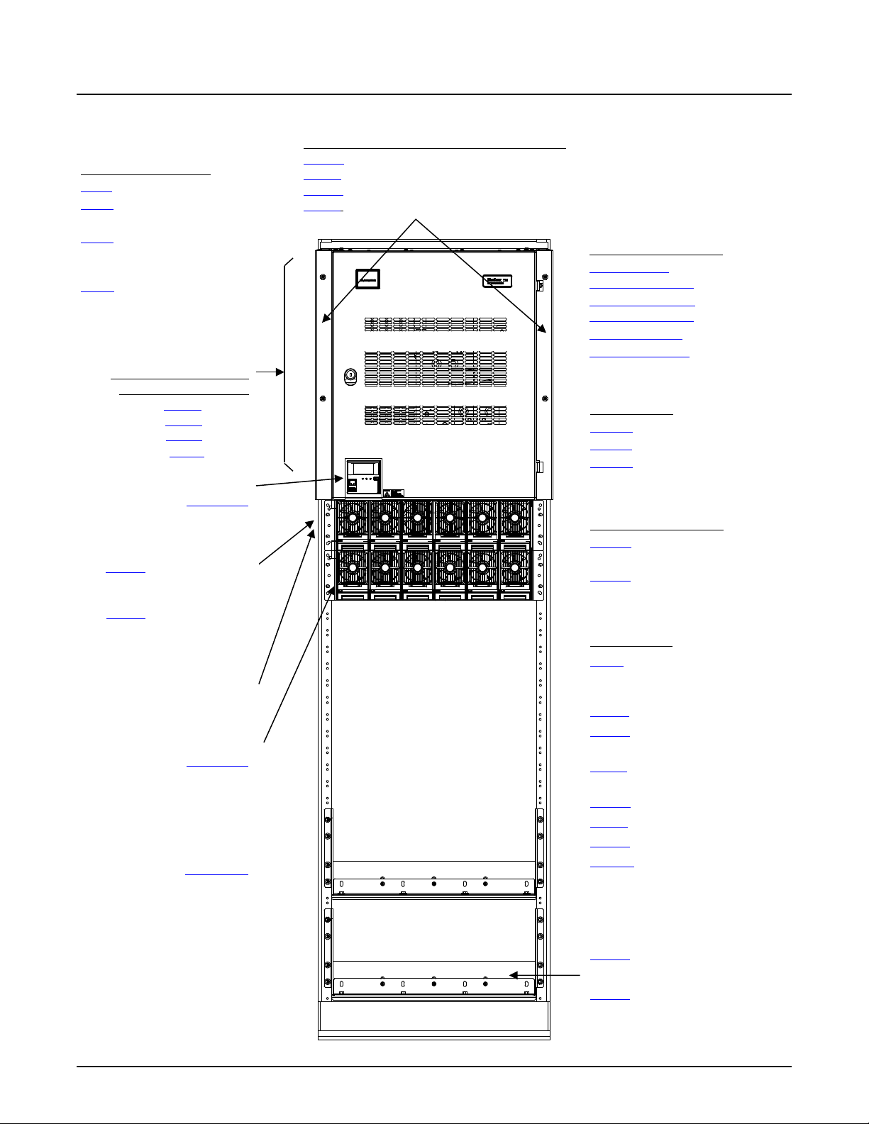
NetSure™ 7100 DC Power System
13
Distri bution Row 1
Distri bution Row 2
Distri bution Row 3
Distri bution Row 4
DISTRIBUTION CABINET
FRONT ACCESS AC TERMINATION ASSEMBLY
Other Options
Controller (Main Bay)
Module Mounting Assembly:
List 30: Module Mounting
System Application Guide
MAIN COMPONENTS ILLUSTRATIONS
582127000 (Relay Rack)
COMMON EQUIPMENT
List 1: Main Bay
List 2: 1st Supplemental Bay, In-
Line w/ Main Bay
rd
List 3: 3
through 6th
Supplemental Bay, In-Line w/
Main Bay
nd
List 5: 2
through 6th
Supplemental Bay, Remote
Location
List 40: 1 AC Feed per 1 Rectifier (1 to 5 Assemblies), Single Phase
List 41: 1 AC Feed per 2 Rectifiers (1 to 5 Assemblies), Single Phase
List 42: 1 AC Feed per 3 Rectifiers (1 to 5 Assemblies), 3-Phase, 3-Wire
List 43: 1 AC Feed per 3 Rectifiers (1 to 5 Assemblies), 3-Phase, 4-Wire
DISTRIBUTION PANELS
Single Voltage
Distribution Panels
Battery Disconnect
Distribution Panels
Return Bar Panel
Bulk Output Panel
(4-Row Cabinet Shown)
List 24 (4-Row)
List 23 (3-Row)
List 22 (2-Row)
List 21 (1-Row)
1M830DNA
SM-DU (Supplemental Bays):
(located behind blank panel)
Assembly Interface
or
List 38: Module Mounting
Assembly Interface
58870500021, 58870500022,
58870500031, 58870500032,
or 58870500033
Rectifier Module:
1R483500e
or
Module Mounting Assembly:
58870550001, 58870550002,
58870550003, 58870550004,
or 58870550005
Rectifier Module:
1R484000e
BATTERY DISCONNECT
CONTACTORS
List CA: 600A
List CB: 1200A
List CC: 2000A
LOW VOLTAGE
DISCONNECT OPTIONS
List LB: Low Voltage Battery
Disconnect (LVBD)
List LL: Low Voltage Load
Disconnect (LVLD)
List 4: Distribution Only Bay
Distribution Cabinet Bottom Rear
Cover
List 28: DC Conduit Box
List 29: Distribution Cabinet
Top Shield
List 31: Module Mounting Assembly
Field Expansion Kit
List 90: Battery Shunt, 800A
List 91: Battery Shunt, 2000A
List 92: Battery Shunt, 2500A
List MB: Manual Battery Disconnect
Spec. No: 582127000 SAG582127000
Model No: 7100 Revision BJ, August 21, 2020
List 93: Optional Battery Tray
or
List 95: Optional Battery Tray
Page 14
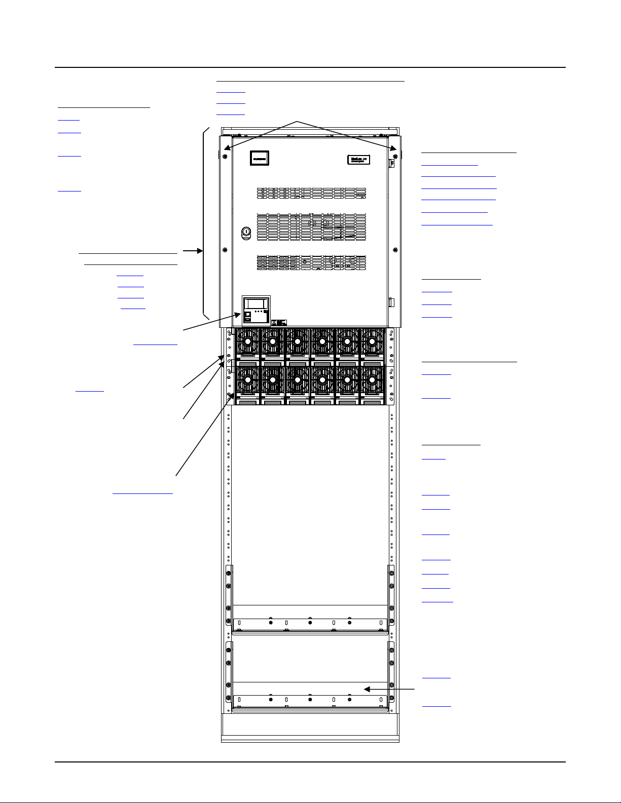
NetSure™ 7100 DC Power System
14
DISTRIBUTION CABINET
FRONT ACCESS DC TERMINATION ASSEMBLY
Other Options
Converter Module:
List 34: Module Mounting
Controller (Main Bay)
Module Mounting Assembly:
Distri bution Row 1
Distri bution Row 2
Distri bution Row 3
Distri bution Row 4
System Application Guide
582127000 (Relay Rack)
COMMON EQUIPMENT
List 1: Main Bay
List 2: 1st Supplemental Bay, In-
Line w/ Main Bay
rd
List 3: 3
through 6th
Supplemental Bay, In-Line w/
Main Bay
nd
List 5: 2
through 6th
Supplemental Bay, Remote
Location
List 45: 1 DC Feed per 1 Converter (1 to 5 Assemblies)
List 46: 1 DC Feed per 2 Converters (2 or 4 Assemblies)
List 47: 1 DC Feed per 3 Converters (1 to 5 Assemblies)
DISTRIBUTION PANELS
Single Voltage
Distribution Panels
Battery Disconnect
Distribution Panels
Return Bar Panel
Bulk Output Panel
(4-Row Cabinet Shown)
List 24 (4-Row)
List 23 (3-Row)
List 22 (2-Row)
List 21 (1-Row)
1M830DNA
SM-DU (Supplemental Bays):
(located behind blank panel)
Assembly Interface
58870500040, 58870500041,
or 58870500042
1C400483500e
BATTERY DISCONNECT
CONTACTORS
List CA: 600A
List CB: 1200A
List CC: 2000A
LOW VOLTAGE
DISCONNECT OPTIONS
List LB: Low Voltage Battery
Disconnect (LVBD)
List LL: Low Voltage Load
Disconnect (LVLD)
List 4: Distribution Only Bay
Distribution Cabinet Bottom Rear
Cover
List 28: DC Conduit Box
List 29: Distribution Cabinet
Top Shield
List 35: Module Mounting Assembly
Field Expansion Kit
List 90: Battery Shunt, 800A
List 91: Battery Shunt, 2000A
List 92: Battery Shunt, 2500A
List MB: Manual Battery Disconnect
Spec. No: 582127000 SAG582127000
Model No: 7100 Revision BJ, August 21, 2020
List 93: Optional Battery Tray
or
List 95: Optional Battery Tray
Page 15
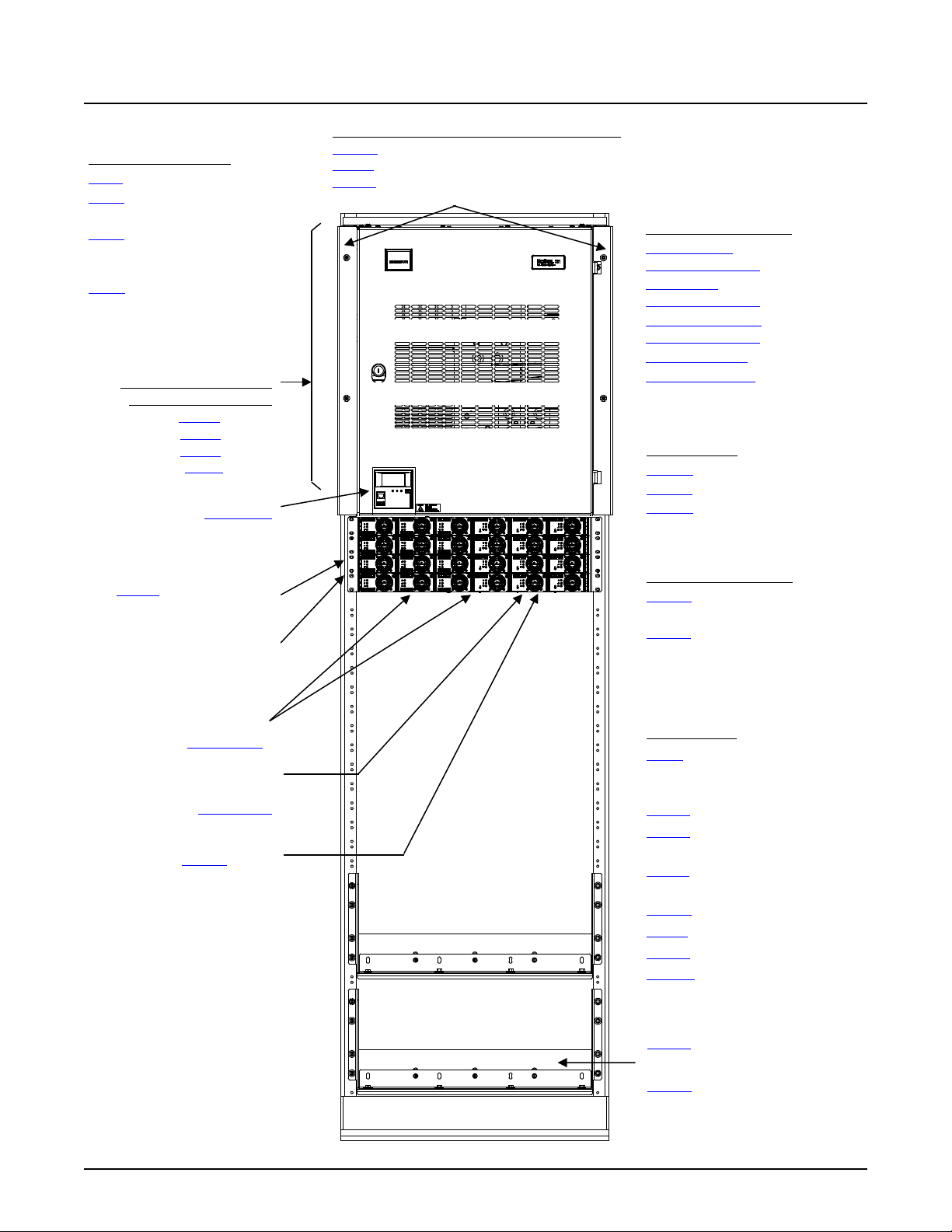
NetSure™ 7100 DC Power System
15
DISTRIBUTION CABINET
FRONT ACCESS AC TERMINATION ASSEMBLY
Other Options
Optional DC-DC
Rectifier Module:
List 32: Module Mounting
Controller (Main Bay)
Module Mounting Assembly:
List 60: DC-DC
Distri bution Row 1
Distri bution Row 2
Distri bution Row 3
Distri bution Row 4
System Application Guide
582127000 (Relay Rack)
COMMON EQUIPMENT
List 1: Main Bay
List 2: 1st Supplemental Bay, In-
Line w/ Main Bay
List 3: 3
Supplemental Bay, In-Line w/
Main Bay
List 5: 2
Supplemental Bay, Remote
Location
rd
through 6th
nd
through 6th
(4-Row Cabinet Shown)
List 24 (4-Row)
List 23 (3-Row)
List 22 (2-Row)
List 21 (1-Row)
1M830DNA
SM-DU (Supplemental Bays):
(located behind blank panel)
Assembly Interface
58870530001, 58870530003
List 40: 1 AC Feed per 1 Rectifier (1 to 5 Assemblies), Single Phase
List 41: 1 AC Feed per 2 Rectifiers (1 to 5 Assemblies), Single Phase
List 42: 1 AC Feed per 3 Rectifiers (1 to 5 Assemblies), 3-Phase, 3-Wire
DISTRIBUTION PANELS
Single Voltage
Distribution Panels
Dual Volage
Distribution Panels
Battery Disconnect
Distribution Panels
Return Bar Panel
Bulk Output Panel
BATTERY DISCONNECT
CONTACTORS
List CA: 600A
List CB: 1200A
List CC: 2000A
LOW VOLTAGE
DISCONNECT OPTIONS
List LB: Low Voltage Battery
Disconnect (LVBD)
List LL: Low Voltage Load
Disconnect (LVLD)
1R482000e3
Converter Module:
1C48241500
Converter Option
Spec. No: 582127000 SAG582127000
Model No: 7100 Revision BJ, August 21, 2020
List 4: Distribution Only Bay
Distribution Cabinet Bottom Rear
Cover
List 28: DC Conduit Box
List 29: Distribution Cabinet
Top Shield
List 33: Module Mounting Assembly
Field Expansion Kit
List 90: Battery Shunt, 800A
List 91: Battery Shunt, 2000A
List 92: Battery Shunt, 2500A
List MB: Manual Battery Disconnect
List 93: Optional Battery Tray
or
List 95: Optional Battery Tray
Page 16
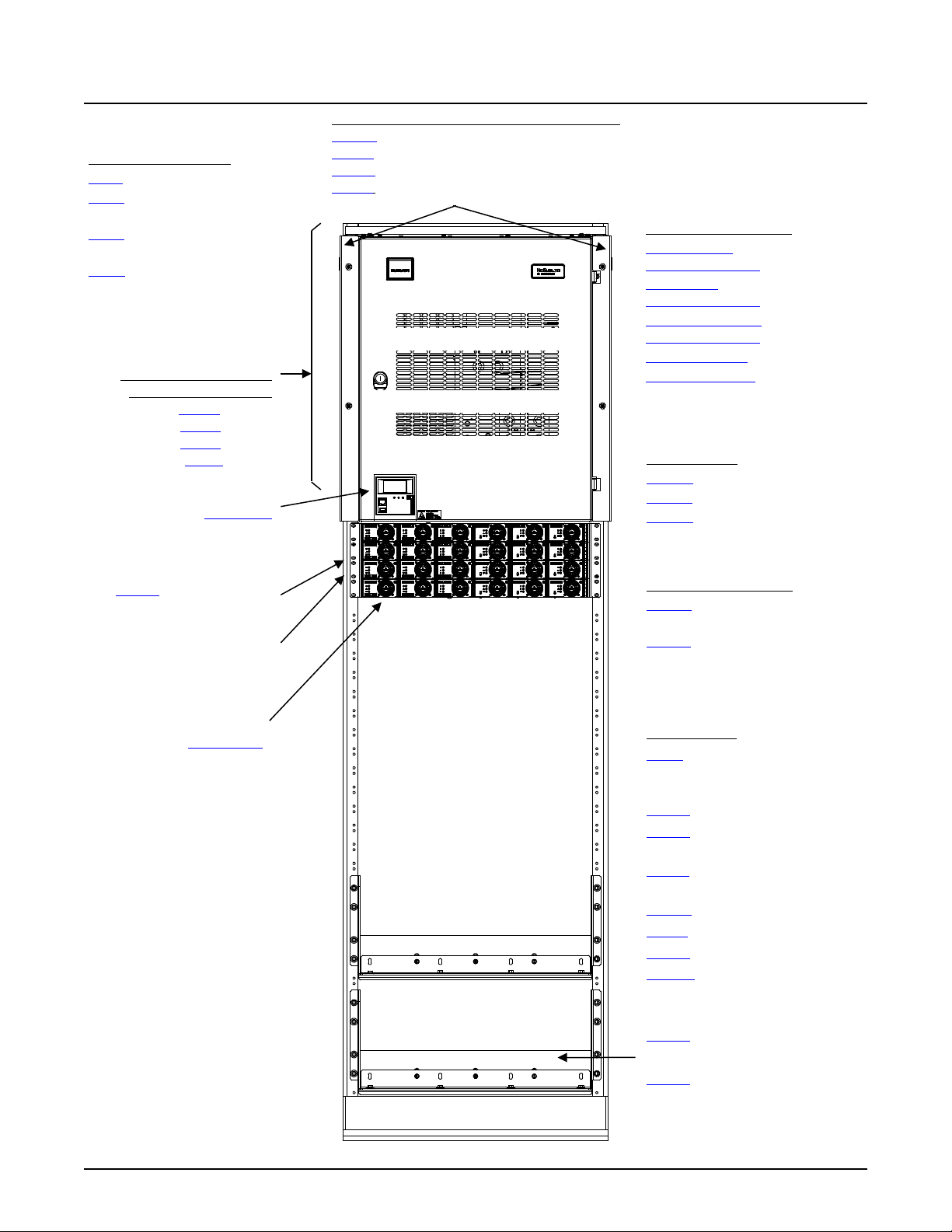
NetSure™ 7100 DC Power System
16
DISTRIBUTION CABINET
FRONT ACCESS AC TERMINATION ASSEMBLY
Other Options
Rectifier Module:
List 36: Module Mounting
Controller (Main Bay)
Module Mounting Assembly:
Distri bution Row 1
Distri bution Row 2
Distri bution Row 3
Distri bution Row 4
System Application Guide
582127000 (Relay Rack)
COMMON EQUIPMENT
List 1: Main Bay
List 2: 1st Supplemental Bay, In-
Line w/ Main Bay
List 3: 3
Bay, In-Line w/ Main Bay
List 5: 2
Supplemental Bay, Remote
Location
58870540003, 558870540004
rd
and 6th Supplemental
nd
through 6th
(4-Row Cabinet Shown)
List 24 (4-Row)
List 23 (3-Row)
List 22 (2-Row)
List 21 (1-Row)
1M830DNA
SM-DU (Supplemental Bays):
(located behind blank panel)
Assembly Interface
58870540001, 58870540002,
List 40: 1 AC Feed per 1 Rectifier (1 to 5 Assemblies), Single Phase
List 41: 1 AC Feed per 2 Rectifiers (1 to 5 Assemblies), Single Phase
List 42: 1 AC Feed per 3 Rectifiers (1 to 5 Assemblies), 3-Phase, 3-Wire
List 43: 1 AC Feed per 3 Rectifiers (1 to 5 Assemblies), 3-Phase, 4-Wire
DISTRIBUTION PANELS
Single Voltage
Distribution Panels
Dual Volage
Distribution Panels
Battery Disconnect
Distribution Panels
Return Bar Panel
Bulk Output Panel
BATTERY DISCONNECT
CONTACTORS
List CA: 600A
List CB: 1200A
List CC: 2000A
LOW VOLTAGE
DISCONNECT OPTIONS
List LB: Low Voltage Battery
Disconnect (LVBD)
List LL: Low Voltage Load
Disconnect (LVLD)
1R483500e3
Spec. No: 582127000 SAG582127000
Model No: 7100 Revision BJ, August 21, 2020
List 4: Distribution Only Bay
Distribution Cabinet Bottom Rear
Cover
List 28: DC Conduit Box
List 29: Distribution Cabinet
Top Shield
List 37: Module Mounting Assembly
Field Expansion Kit
List 90: Battery Shunt, 800A
List 91: Battery Shunt, 2000A
List 92: Battery Shunt, 2500A
List MB: Manual Battery Disconnect
List 93: Optional Battery Tray
or
List 95: Optional Battery Tray
Page 17

NetSure™ 7100 DC Power System
17
DISTRIBUTION CABINET
FRONT ACCESS
Other Features
Optional DC-DC
Rectifier Module:
NCU Controller
Module Mounting Assemblies:
10009902 Relay Rack
System Application Guide
582127000 List 100 (Relay Rack)
(3-Row)
DISTRIBUTION PANELS
582127000 List DJ
582127000 List AL
582127000 List AL
1M830DNA
BATTERY DISCONNECT
CONTACTOR
AC TERMINATION ASSEMBLY
1 AC Feed per 2 Rectifiers,
Single Phase (both sides)
58870530021
58870530001
58870530001
58870530001
1R482000e3
Converter Module:
1C48241500
Battery Shunt: 1500 A, 25 mV
Manual Battery Disconnect
System Interface Board
IB4 Board (second Ethernet port)
IB2 Board
Optional EIB Board
Spec. No: 582127000 SAG582127000
Model No: 7100 Revision BJ, August 21, 2020
Page 18
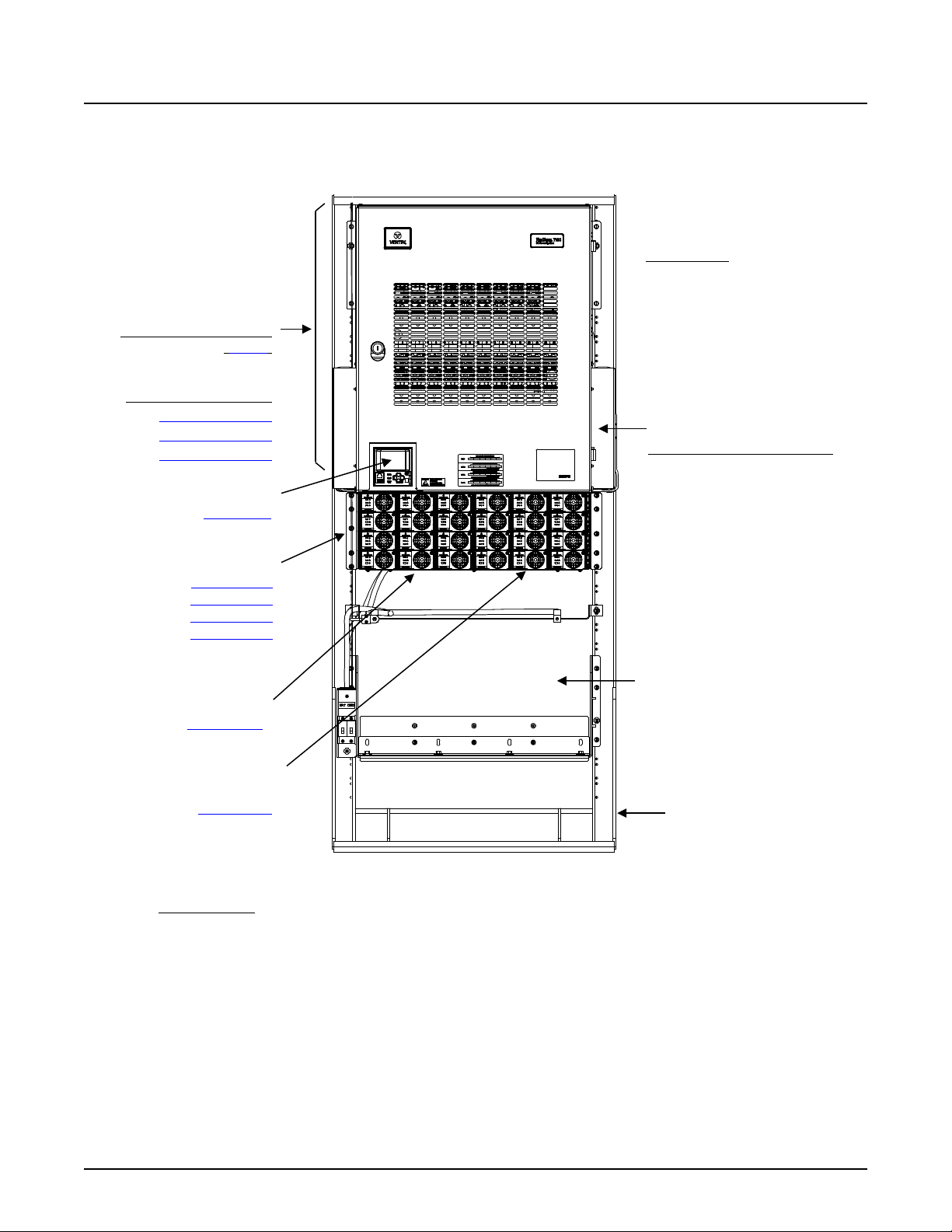
NetSure™ 7100 DC Power System
18
DISTRIBUTION CABINET
FRONT ACCESS
Other Features
Optional DC-DC
Rectifier Module:
NCU Controller
Module Mounting Assemblies:
564169 Relay Rack
System Application Guide
582127000 List 101 (Relay Rack)
(3-Row)
DISTRIBUTION PANELS
582127000 List DJ
582127000 List AL
582127000 List AL
1M830DNA
BATTERY DISCONNECT
CONTACTOR
AC TERMINATION ASSEMBLY
1 AC Feed per 2 Rectifiers,
Single Phase (both sides)
58870530021
58870530001
58870530001
58870530001
1R482000e3
Converter Module:
1C48241500
Battery Shunt: 1500 A, 25 mV
Manual Battery Disconnect
System Interface Board
IB4 Board (second Ethernet port)
IB2 Board
Optional EIB Board
Battery Tray
(with 200 A Circuit Breakers)
Spec. No: 582127000 SAG582127000
Model No: 7100 Revision BJ, August 21, 2020
Page 19
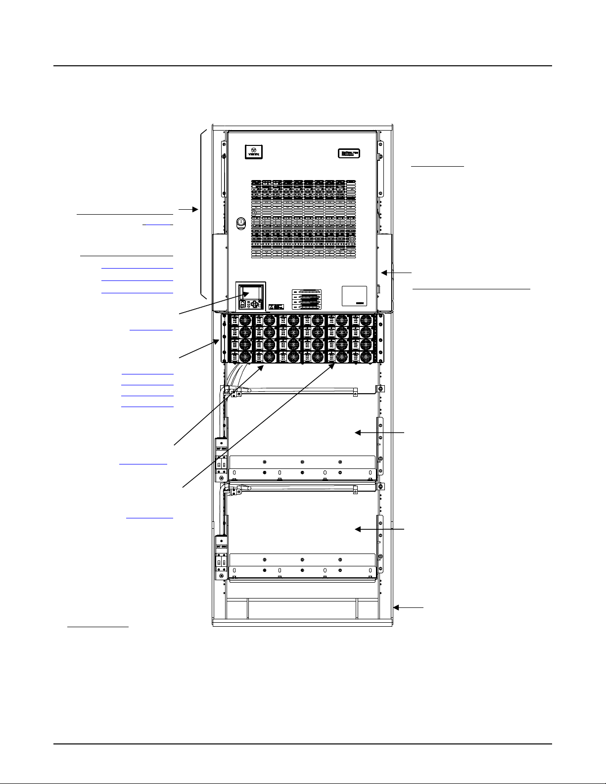
NetSure™ 7100 DC Power System
19
DISTRIBUTION CABINET
FRONT ACCESS
Other Features
Optional DC-DC
Rectifier Module:
NCU Controller
Module Mounting Assemblies:
564127 Relay Rack
System Application Guide
582127000 List 102 (Relay Rack)
(3-Row)
DISTRIBUTION PANELS
582127000 List DJ
582127000 List AL
582127000 List AL
1M830DNA
BATTERY DISCONNECT
CONTACTOR
AC TERMINATION ASSEMBLY
1 AC Feed per 2 Rectifiers,
Single Phase (both sides)
58870530021
58870530001
58870530001
58870530001
Battery Tray
(with 200 A Circuit Breakers)
1R482000e3
Converter Module:
1C48241500
Battery Tray
(with 200 A Circuit Breakers)
Battery Shunt: 1500 A, 25 mV
Manual Battery Disconnect
System Interface Board
IB4 Board (second Ethernet port)
IB2 Board
Optional EIB Board
Spec. No: 582127000 SAG582127000
Model No: 7100 Revision BJ, August 21, 2020
Page 20
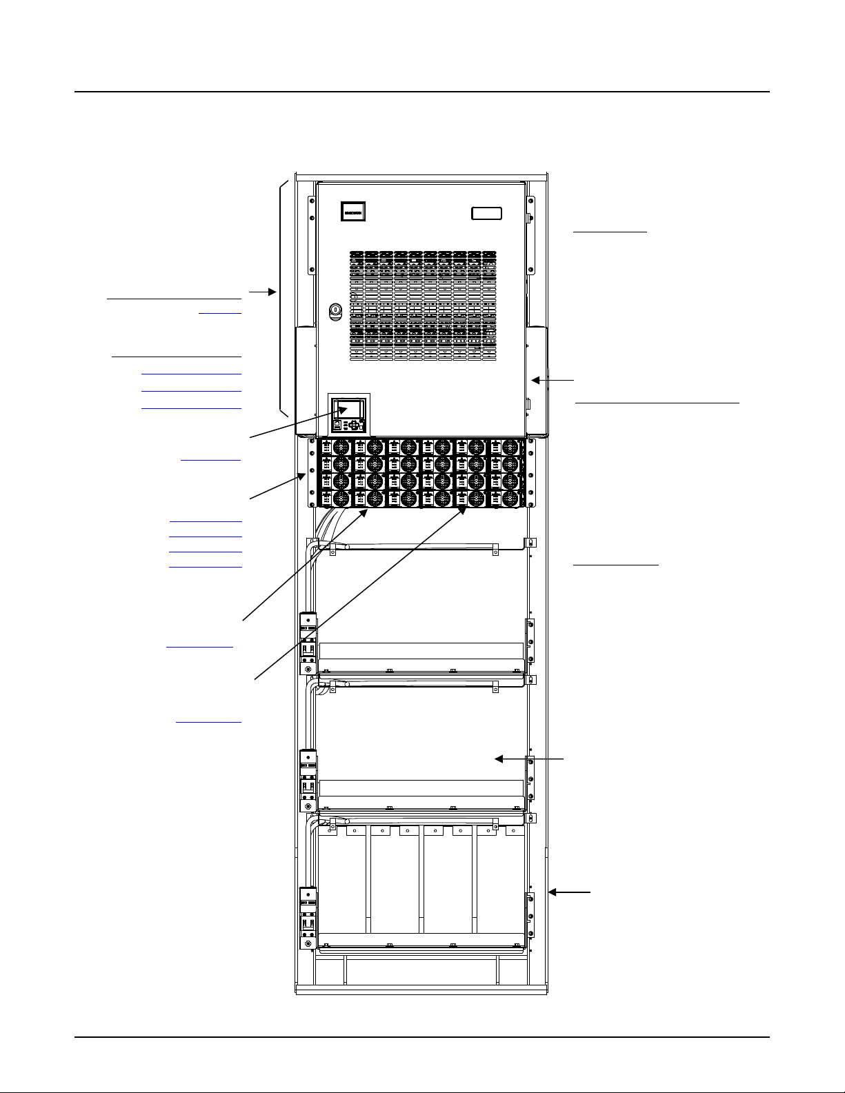
NetSure™ 7100 DC Power System
20
DISTRIBUTION CABINET
FRONT ACCESS
Other Features
Optional DC-DC
Rectifier Module:
NCU Controller
Module Mounting Assemblies:
10009902 Relay Rack
System Application Guide
582127000 List 103 (Relay Rack)
(3-Row)
DISTRIBUTION PANELS
582127000 List DJ
582127000 List AL
582127000 List AL
1M830DNA
BATTERY DISCONNECT
CONTACTOR
AC TERMINATION ASSEMBLY
1 AC Feed per 2 Rectifiers,
Single Phase (both sides)
58870530021
58870530001
58870530001
58870530001
1R482000e3
Converter Module:
1C48241500
Battery Shunt: 1500 A, 25 mV
Manual Battery Disconnect
System Interface Board
IB4 Board (second Ethernet port)
IB2 Board
Optional EIB Board
Battery Trays
(with 150 A Circuit Breakers)
Spec. No: 582127000 SAG582127000
Model No: 7100 Revision BJ, August 21, 2020
Page 21
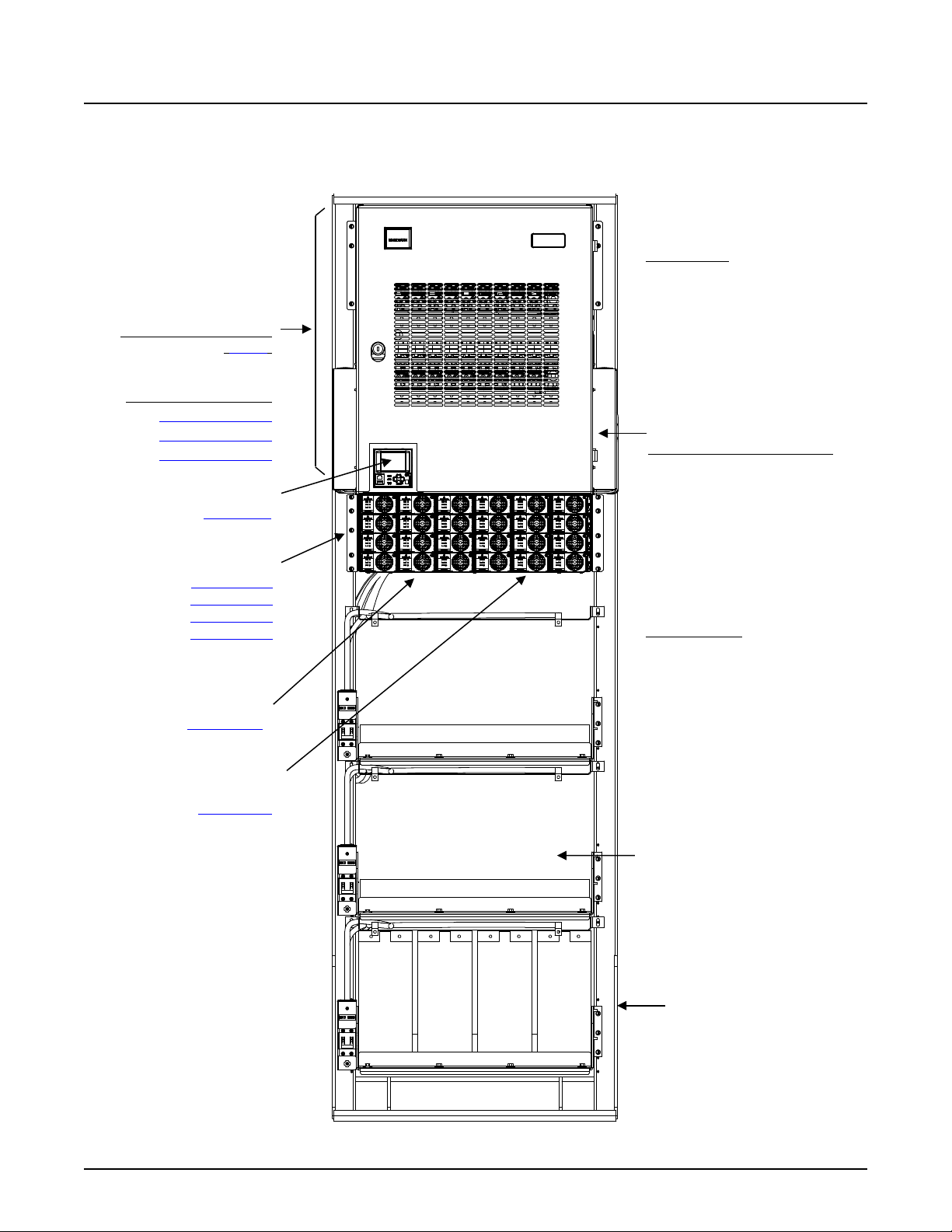
NetSure™ 7100 DC Power System
21
DISTRIBUTION CABINET
FRONT ACCESS
Other Features
Optional DC-DC
Rectifier Module:
NCU Controller
Module Mounting Assemblies:
10009902 Relay Rack
System Application Guide
582127000 List 203 (Relay Rack)
(3-Row)
DISTRIBUTION PANELS
582127000 List DJ
582127000 List AL
582127000 List AL
1M830DNA
BATTERY DISCONNECT
CONTACTOR
AC TERMINATION ASSEMBLY
1 AC Feed per 2 Rectifiers,
Single Phase (both sides)
58870530021
58870530001
58870530001
58870530001
1R482000e3
Converter Module:
1C48241500
Battery Shunt: 1500 A, 25 mV
Manual Battery Disconnect
System Interface Board
IB4 Board (second Ethernet port)
IB2 Board
Optional EIB Board
Battery Trays
(with 200 A Circuit Breakers)
Spec. No: 582127000 SAG582127000
Model No: 7100 Revision BJ, August 21, 2020
Page 22

NetSure™ 7100 DC Power System
22
DISTRIBUTION CABINET
FRONT ACCESS AC TERMINATION ASSEMBLY (Inside Distribution Cabinet)
Other Options
List 30: Module Mounting
Controller (Main Bay)
(located behind blank panel)
Enclosure
Module Mounting Assembly:
System Application Guide
582127000 (Enclosure)
COMMON EQUIPMENT
List 1: Main Bay
List 7: 1st Supplemental Bay, In-
Line w/ Main Bay
List 8: 3
Bay, In-Line w/ Main Bay
rd
and 6th Supplemental
(4-Row Cabinet Shown)
List 24 (4-Row)
List 23 (3-Row)
List 40: 1 AC Feed per 1 Rectifier (1 to 6 Assemblies), Single Phase
List 41: 1 AC Feed per 2 Rectifiers (1 to 6 Assemblies), Single Phase
List 42: 1 AC Feed per 3 Rectifiers (1 to 6 Assemblies), 3-Phase, 3-Wire
List 43: 1 AC Feed per 3 Rectifiers (1 to 6 Assemblies), 3-Phase, 4-Wire
DISTRIBUTION PANELS
Single Voltage
Distribution Panels
Battery Disconnect
Distribution Panels
Return Bar Panel
Bulk Output Panel
BATTERY DISCONNECT
CONTACTORS
List CA: 600A
List CB: 1200A
List CC: 2000A
SM-DU (Supplemental Bays):
Assembly Interface
List 38: Module Mounting
Assembly Interface
58870500021, 58870500022,
58870500031, 58870500032,
Module Mounting Assembly:
58870550001, 58870550002,
58870550003, 58870550004,
1M830DNA
or
or 58870500033
Rectifier Module:
1R483500e
or
or 58870550005
Rectifier Module:
1R484000e
LOW VOLTAGE
DISCONNECT OPTIONS
List LB: Low Voltage Battery
Disconnect (LVBD)
List LL: Low Voltage Load
Disconnect (LVLD)
List 4: Distribution Only Bay
Distribution Cabinet Bottom Rear
Cover
List 31: Module Mounting Assembly
Field Expansion Kit
List 92: Battery Shunt, 2500A
List MB: Manual Battery Disconnect
(563524 or 564881)
Spec. No: 582127000 SAG582127000
Model No: 7100 Revision BJ, August 21, 2020
Page 23
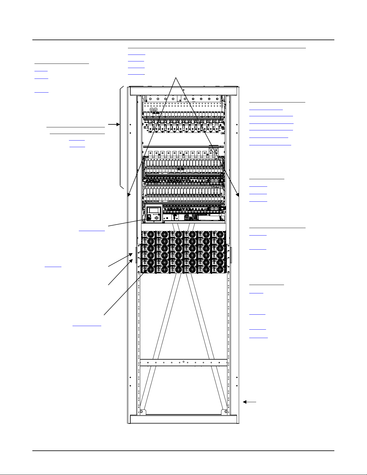
NetSure™ 7100 DC Power System
23
DISTRIBUTION CABINET
FRONT ACCESS AC TERMINATION ASSEMBLY (Inside Distribution Cabinet)
Other Options
Rectifier Module Positions:
List 36: Module Mounting
Controller (Main Bay)
Module Mounting Assembly:
Enclosure
System Application Guide
582127000 (Enclosure)
COMMON EQUIPMENT
List 1: Main Bay
List 7: 1st Supplemental Bay, In-
Line w/ Main Bay
List 8: 3
Bay, In-Line w/ Main Bay
rd
and 6th Supplemental
(4-Row Cabinet Shown)
List 24 (4-Row)
List 23 (3-Row)
List 40: 1 AC Feed per 1 Rectifier (1 to 6 Assemblies), Single Phase
List 41: 1 AC Feed per 2 Rectifiers (1 to 6 Assemblies), Single Phase
List 42: 1 AC Feed per 3 Rectifiers (1 to 6 Assemblies), 3-Phase, 3-Wire
List 43: 1 AC Feed per 3 Rectifiers (1 to 6 Assemblies), 3-Phase, 4-Wire
DISTRIBUTION PANELS
Single Voltage
Distribution Panels
Battery Disconnect
Distribution Panels
Return Bar Panel
Bulk Output Panel
BATTERY DISCONNECT
CONTACTORS
List CA: 600A
List CB: 1200A
List CC: 2000A
1M830DNA
SM-DU (Supplemental Bays):
(located behind blank panel)
Assembly Interface
58870540001, 58870540002,
58870540003, 558870540004
1R483500e3
LOW VOLTAGE
DISCONNECT OPTIONS
List LB: Low Voltage Battery
Disconnect (LVBD)
List LL: Low Voltage Load
Disconnect (LVLD)
List 4: Distribution Only Bay
Distribution Cabinet Bottom Rear
Cover
List 37: Module Mounting Assembly
Field Expansion Kit
List 92: Battery Shunt, 2500A
List MB: Manual Battery Disconnect
Spec. No: 582127000 SAG582127000
Model No: 7100 Revision BJ, August 21, 2020
(563524 or 564881)
Page 24

NetSure™ 7100 DC Power System
24
System Application Guide
LIST DESCRIPTIONS (582127000)
List Numbers (582127000)
List 1: Main Bay Common Equipment (Power and Distribution), For System Mounted in a Relay Rack, on Shipping Rails, or in
an Enclosure
Features
♦ Provides common equipment for one “power and distribution” bay rated for up to 2000 amperes of distribution. System
components factory mounted in a relay rack, on shipping rails, or in an enclosure as specified when ordered.
♦ Accepts one (1) distribution cabinet (options are 1-row, 2-row, 3-row, or 4-row cabinet). 1-row and 2-row distribution
cabinets are only available in the relay rack or shipping rails option.
♦ Accepts one (1) controller.
♦ Includes the IB2 controller interface board (provides eight (8) programmable form C- relay outputs, eight (8)
programmable binary inputs, and two (2) temperature inputs).
♦ Accepts a second optional IB2 controller interface board. See Restrictions. See page 92.
♦ Accepts the optional EIB controller extended interface board (provides five (5) programmable form-C relay outputs, two
(2) temperature inputs, three (3) shunt inputs. and eight (8) battery midpoint inputs).
♦ Accepts a second optional EIB controller extended interface board. See Restrictions. See page 93.
♦ Accepts up to six (6) module mounting assemblies Spec. No. 588705000 or 588705400 or 588705500 (including
expansion assemblies).
or
Accepts up to six (6) module mounting assemblies Spec. No. 588705300 (including expansion assemblies). Relay rack or
shipping rails option only.
Restrictions
System components factory mounted in a relay rack, on shipping rails, or in an enclosure as specified when ordered.
Cannot put a system installed in an enclosure next to a system installed in a relay rack.
When the system is equipped with a List 40, 41, 42, 43, 45, 46, or 47 front access input termination assembly, refer to the
restrictions under these list descriptions. List 45, 46, 47 available with relay rack option only.
The system can contain a maximum of three (3) Interface Boards, (1) IB2 and (2) EIB or (2) IB2 and (1) EIB.
Cannot include List 93 and List 95 battery tray option if it is to be used in conjunction with a List 2 adjacent supplemental bay.
Ordering Notes
1) Order a relay rack or shipping brackets per “Relay Racks and Shipping Brackets” on page 110 if desired. If required, order
relay rack transition plates per “Transition Plates to Mount Relay Rack on Top of GNB Absolyte IIP Batteries” on page 111.
A relay rack, shipping rails, or enclosure must be specified when ordered.
2) Order an enclosure per “Enclosure” on page 112 if desired. A relay rack, shipping rails, or enclosure must be specified
when ordered.
3) Order one (1) List 21, 22, 23, or 24 distribution cabinet. List 21 and List 22 distribution cabinets are only available in the
relay rack or shipping rails option.
a) Order up to four (4) (per the capacity of the distribution cabinet ordered) distribution panels, battery disconnect
panels, return bar panel, and/or bulk output panel as required per “Single Voltage Distribution Panel”, “Dual Voltage
Distribution Panel”, “Battery Disconnect Distribution Panel”, “Return Bar Panel”, and “Bulk Output Panel” starting on
page 56. Dual voltage panels are not available in the enclosure option.
b) Order battery disconnect contactors and low voltage disconnect options as required per “Battery Disconnect
Contactors” and “Low Voltage Disconnect Options” starting on page 89.
c) Order one (1) NCU controller (P/N 1M830DNA).
d) Order optional second IB2 controller interface board as required. See Restrictions. See page 92.
e) Order the optional EIB controller extended interface board as required (see page 93).
f) Order optional second EIB controller interface board as required. See Restrictions. See page 93.
g) Order fuses and/or circuit breakers as required per “Distribution Devices” starting on page 118.
h) Order input and load distribution lugs, lug adapters, and lug hardware kits as required per “Recommended Wire
Sizes, Branch Circuit Protection, Crimp Lugs, and Wiring Illustrations” starting on page 131.
i) Order a DC conduit box as required per List 28. Not available in the enclosure option.
Spec. No: 582127000 SAG582127000
Model No: 7100 Revision BJ, August 21, 2020
Page 25

NetSure™ 7100 DC Power System
25
System Application Guide
j) Order a distribution cabinet top shield as required per List 29. Not available in the enclosure option.
k) Order a battery shunt as required per List 90, 91, or 92.
l) Refer to “In-Line Fuse and Resistor Pigtail Kits” on page 93 for in-line resistor pigtails for use with shunt inputs and
in-line fuse pigtails for use with battery midpoint inputs connected to an IB2 or EIB.
4) 1R483500e Rectifier Option: Order interface components for module mounting assembly(s) Spec. No. 588705000 as
required per List 30. Order field expansion module mounting assembly(s) per List 31. Order module mounting
assembly(s) as required. See “Module Mounting Assembly” starting on page 99 (choices are 58870500021,
58870500022, 58870500031, 58870500032, 58870500033).
a) Order the front access AC Input Termination Assembly per List 40, 41, 42, or 43 if module mounting assembly
58870500021 ordered (or order module mounting assemblies with AC line cords or terminal blocks; 58870500022,
58870500031, 58870500032, 58870500033). See “Module Mounting Assembly” starting on page 99.)
b) Order rectifier modules as required, P/N 1R483500e.
c) Order a module mounting position blank cover panel, P/N 21140440, for each empty module mounting position in the
system, as desired.
5) 1C400483500e Converter Option: Order interface components for module mounting assembly(s) Spec. No. 588705000
as required per List 34. Order field expansion module mounting assembly(s) per List 35. Order module mounting
assembly(s) as required. See “Module Mounting Assembly” starting on page 99 (choices are 58870500040,
58870500041, 58870500042).
a) Order the front access DC Input Termination Assembly per List 45, 46, or 47 if module mounting assembly
58870500040 ordered (or order module mounting assemblies with terminal blocks; 58870500041, 58870500042.
See “Module Mounting Assembly” starting on page 99).
b) Order converter modules as required, P/N 1C400483500e.
c) Order a module mounting position blank cover panel, P/N 21140440, for each empty module mounting position in the
system, as desired.
6) 1R482000e3 Rectifier / 1C48241500 Converter Option: Order interface components for module mounting assembly(s)
Spec. No. 588705300 as required per List 32. Order field expansion module mounting assembly(s) per List 33. Order
module mounting assembly(s) as required. See “Module Mounting Assembly” starting on page 99 (choices are
58870530001, 58870530003). Not available in the enclosure option.
a) Order the front access AC Input Termination Assembly per List 40, 41, or 42 if module mounting assembly
58870530001 ordered (or order module mounting assemblies that accommodate AC input cable assemblies or line
cords; 58870530003. See “Module Mounting Assembly” starting on page 99).
b) Order rectifier modules as required, P/N 1R482000e3.
c) Order optional converter interface components per List 60.
d) Order optional DC-DC converter modules as required, P/N 1C48241500.
e) Order a module mounting position blank cover panel, P/N SXA1100035/1, for each empty module mounting position
in the system, as desired.
7) 1R483500e3 Rectifier Option: Order interface components for module mounting assembly(s) Spec. No. 588705400 as
required per List 36. Order field expansion module mounting assembly(s) per List 37. Order module mounting
assembly(s) as required. See “Module Mounting Assembly” starting on page 99 (choices are 58870540001,
58870540002, 58870540003, 58870540004).
a) Order the front access AC Input Termination Assembly per List 40, 41, 42, or 43 if module mounting assembly
58870540001 ordered (or order module mounting assemblies that accommodate AC input cable assemblies or line
cords; 58870540002, 58870540003, 58870540004. See “Module Mounting Assembly” starting on page 99).
b) Order rectifier modules as required, P/N 1R483500e3.
c) Order a module mounting position blank cover panel, P/N SXA1100035/1, for each empty module mounting position
in the system, as desired.
8) 1R484000e Rectifier Option: Order interface components for module mounting assembly(s) Spec. No. 588705500 as
required per List 38. Order field expansion module mounting assembly(s) per List 39. Order module mounting
assembly(s) as required. See “Module Mounting Assembly” starting on page 99 (choices are 58870550001,
58870550002, 58870550003, 58870550004, 58870550005).
a) Order the front access AC Input Termination Assembly per List 40, 41, 42, or 43 if module mounting assembly
58870550001ordered (or order module mounting assemblies with AC line cords or terminal blocks; 58870550002,
58870550003, 58870550004, 58870550005). See “Module Mounting Assembly” starting on page 99.)
b) Order rectifier modules as required, P/N 1R484000e.
Spec. No: 582127000 SAG582127000
Model No: 7100 Revision BJ, August 21, 2020
Page 26

NetSure™ 7100 DC Power System
26
System Application Guide
c) Order a module mounting position blank cover panel, P/N 21140440, for each empty module mounting position in the
system, as desired.
9) Order battery trays as required per List 93 or List 95. Not available in the shipping rails option.
a) Order batteries as required per “Batteries” on page 50.
b) Order “Optional Battery Tray Battery Disconnect Circuit Breaker and Housing Kits” as required.
c) Order “Optional Battery Tray Front Battery Cover Kits” as required.
List 2: 1
Bay, For System Mounted in a Relay Rack Only
st
Supplemental Bay Common Equipment (Power and Distribution or Distribution Only), Located In-Line with Main
Features
♦ Provides common equipment for one bussed “power and distribution or distribution only” bay rated for up to 2000
amperes of distribution. Includes interbay power busbars and communications cable. System components factory
mounted in a relay rack as specified when ordered.
♦ Mounts to either left or right side of List 1 Main Bay.
♦ Accepts one (1) distribution cabinet (options are 3-row or 4-row cabinet).
♦ Includes SM-DU (provides bay interface to the system controller).
♦ Accepts up to six (6) module mounting assemblies Spec. No. 588705000 or 588705300 or 588705400 or 588705500
(including expansion assemblies).
Restrictions
System components factory mounted in a relay rack as specified when ordered. Not available with enclosure or shipping rails.
When the system is equipped with a List 40, 41, 42, 43, 45, 46, or 47 front access input termination assembly, refer to the
restrictions under these list descriptions.
Will not accept List 21 and 22 distribution cabinet.
(List 21 and 22 are not provided with connection points for interbay busbars.)
Will not accept List 60 converter interface components.
Will not accept dual voltage distribution panels.
Will not accept List 93 and List 95 battery trays option.
Order maximum of one (1) List 2.
Rear access required for installation of inter-bay busbars.
If low voltage disconnect (List LL) is to be included, the Main Bay (List 1) of the system must also have low voltage disconnect
(List LL or List LB).
Ordering Notes
1) Order a relay rack per “Relay Racks and Shipping Brackets” on page 110.
2) Order one (1) List 23 or 24 distribution cabinet.
a) Order up to four (4) (per the capacity of the distribution cabinet ordered) distribution panels, battery disconnect
panels, return bar panel, and/or bulk output panel as required per “Single Voltage Distribution Panel”, “Battery
Disconnect Distribution Panel”, “Return Bar Panel”, and “Bulk Output Panel” starting on page 56.
b) Order low voltage disconnect options as required per “Low Voltage Disconnect Options” starting on page 90.
c) Order fuses and/or circuit breakers as required per “Distribution Devices” starting on page 118.
d) Order input and load distribution lugs, lug adapters, and lug hardware kits as required per “Recommended Wire
Sizes, Branch Circuit Protection, Crimp Lugs, and Wiring Illustrations” starting on page 131.
e) Order a DC conduit box as required per List 28.
f) Order a distribution cabinet top shield as required per List 29.
g) If distribution only, order a bottom rear distribution cabinet cover per List 4.
h) Order a battery shunt as required per List 90, 91, or 92.
3) 1R483500e Rectifier Option: Order interface components for module mounting assembly(s) Spec. No. 588705000 as
required per List 30. Order field expansion module mounting assembly(s) per List 31. Order module mounting
assembly(s) as required. See “Module Mounting Assembly” starting on page 99 (choices are 58870500021,
58870500022, 58870500031, 58870500032, 58870500033).
Spec. No: 582127000 SAG582127000
Model No: 7100 Revision BJ, August 21, 2020
Page 27

NetSure™ 7100 DC Power System
27
System Application Guide
a) Order the front access AC Input Termination Assembly per List 40, 41, 42, or 43 if module mounting assembly
58870500021 ordered (or order module mounting assemblies with AC line cords or terminal blocks; 58870500022,
58870500031, 58870500032, 58870500033. See “Module Mounting Assembly” starting on page 99).
b) Order rectifier modules as required, P/N 1R483500e.
c) Order a module mounting position blank cover panel, P/N 21140440, for each empty module mounting position in the
system, as desired.
4) 1C400483500e Converter Option: Order interface components for module mounting assembly(s) Spec. No. 588705000
as required per List 34. Order field expansion module mounting assembly(s) per List 35. Order module mounting
assembly(s) as required. See “Module Mounting Assembly” starting on page 99 (choices are 58870500040,
58870500041, 58870500042).
a) Order the front access DC Input Termination Assembly per List 45, 46, or 47 if module mounting assembly
58870500040 ordered (or order module mounting assemblies with terminal blocks; 58870500041, 58870500042.
See “Module Mounting Assembly” starting on page 99).
b) Order converter modules as required, P/N 1C400483500e.
c) Order a module mounting position blank cover panel, P/N 21140440, for each empty module mounting position in the
system, as desired.
5) 1R482000e3 Rectifier Option: Order interface components for module mounting assembly(s) Spec. No. 588705300 as
required per List 32. Order field expansion module mounting assembly(s) per List 33. Order module mounting
assembly(s) as required. See “Module Mounting Assembly” starting on page 99 (choices are 58870530001,
58870530003).
a) Order the front access AC Input Termination Assembly per List 40, 41, or 42 if module mounting assembly
58870530001 ordered (or order module mounting assemblies that accommodate AC input cable assemblies or line
cords; 58870530003. See “Module Mounting Assembly” starting on page 99).
b) Order rectifier modules as required, P/N 1R482000e3.
c) Order a module mounting position blank cover panel, P/N SXA1100035/1, for each empty module mounting position
in the system, as desired.
6) 1R483500e3 Rectifier Option: Order interface components for module mounting assembly(s) Spec. No. 588705400 as
required per List 36. Order field expansion module mounting assembly(s) per List 37. Order module mounting
assembly(s) as required. See “Module Mounting Assembly” starting on page 99 (choices are 58870540001,
58870540002, 58870540003, 58870540004).
a) Order the front access AC Input Termination Assembly per List 40, 41, 42, or 43 if module mounting assembly
58870540001 ordered (or order module mounting assemblies that accommodate AC input cable assemblies or line
cords; 58870540002, 58870540003, 58870540004. See “Module Mounting Assembly” starting on page 99).
b) Order rectifier modules as required, P/N 1R483500e3.
c) Order a module mounting position blank cover panel, P/N SXA1100035/1, for each empty module mounting position
in the system, as desired.
7) 1R484000e Rectifier Option: Order interface components for module mounting assembly(s) Spec. No. 588705500 as
required per List 38. Order field expansion module mounting assembly(s) per List 39. Order module mounting
assembly(s) as required. See “Module Mounting Assembly” starting on page 99 (choices are 58870550001,
58870550002, 58870550003, 58870550004, 58870550005).
a) Order the front access AC Input Termination Assembly per List 40, 41, 42, or 43 if module mounting assembly
58870550001ordered (or order module mounting assemblies with AC line cords or terminal blocks; 58870550002,
58870550003, 58870550004, 58870550005). See “Module Mounting Assembly” starting on page 99.)
b) Order rectifier modules as required, P/N 1R484000e.
c) Order a module mounting position blank cover panel, P/N 21140440, for each empty module mounting position in the
system, as desired.
List 3: 3
with Main Bay, For System Mounted in a Relay Rack Only
rd
through 6th Supplemental Bays Common Equipment (Power and Distribution or Distribution Only), Located In-Line
Features
♦ Provides common equipment for one bussed “power and distribution or distribution only” bay rated for up to 2000
amperes of distribution. Includes interbay power busbars and communications cable. System components factory
mounted in a relay rack as specified when ordered.
♦ Mounts to either left or right side of List 2 Supplemental Bay or another List 3 Supplementary bay.
Spec. No: 582127000 SAG582127000
Model No: 7100 Revision BJ, August 21, 2020
Page 28

NetSure™ 7100 DC Power System
28
System Application Guide
♦ Accepts one (1) distribution cabinet (options are 3-row or 4-row cabinet).
♦ Includes SM-DU (provides bay interface to the system controller).
♦ Accepts up to six (6) module mounting assemblies Spec. No. 588705000 or 588705300 or 588705400 or 588705500
(including expansion assemblies).
Restrictions
System components factory mounted in a relay rack as specified when ordered. Not available with enclosure or shipping rails.
When the system is equipped with a List 40, 41, 42, 43, 45, 46, or 47 front access input termination assembly, refer to the
restrictions under these list descriptions.
Will not accept List 21 and 22 distribution cabinet.
(List 21 and 22 are not provided with connection points for interbay busbars.)
Will not accept List 60 converter interface components.
Will not accept dual voltage distribution panels.
Order maximum of five (5) List 3.
Will not accept List 93 and List 95 battery trays option.
Rear access required for installation of inter-bay busbars.
If low voltage disconnect (List LL) is to be included, the Main Bay (List 1) of the system must also have low voltage disconnect
(List LL or List LB).
Ordering Notes
1) Order a relay rack per “Relay Racks and Shipping Brackets” on page 110.
2) Order one (1) List 23 or 24 distribution cabinet.
a) Order up to four (4) (per the capacity of the distribution cabinet ordered) distribution panels, battery disconnect
panels, return bar panel, and/or bulk output panel as required per “Single Voltage Distribution Panel”, “Battery
Disconnect Distribution Panel”, “Return Bar Panel”, and “Bulk Output Panel” starting on page 56.
b) Order low voltage disconnect options as required per “Low Voltage Disconnect Options” starting on page 90.
c) Order fuses and/or circuit breakers as required per “Distribution Devices” starting on page 118.
d) Order input and load distribution lugs, lug adapters, and lug hardware kits as required per “Recommended Wire
Sizes, Branch Circuit Protection, Crimp Lugs, and Wiring Illustrations” starting on page 131.
e) Order a DC conduit box as required per List 28.
f) Order a distribution cabinet top shield as required per List 29.
g) If distribution only, order a bottom rear distribution cabinet cover per List 4.
h) Order a battery shunt as required per List 90, 91, or 92.
3) 1R483500e Rectifier Option: Order interface components for module mounting assembly(s) Spec. No. 588705000 as
required per List 30. Order field expansion module mounting assembly(s) per List 31. Order module mounting
assembly(s) as required. See “Module Mounting Assembly” starting on page 99 (choices are 58870500021,
58870500022, 58870500031, 58870500032, 58870500033).
a) Order the front access AC Input Termination Assembly per List 40, 41, 42, or 43 if module mounting assembly
58870500021 ordered (or order module mounting assemblies with AC line cords or terminal blocks; 58870500022,
58870500031, 58870500032, 58870500033. See “Module Mounting Assembly” starting on page 99).
b) Order rectifier modules as required, P/N 1R483500e.
c) Order a module mounting position blank cover panel, P/N 21140440, for each empty module mounting position in the
system, as desired.
4) 1C400483500e Converter Option: Order interface components for module mounting assembly(s) Spec. No. 588705000
as required per List 34. Order field expansion module mounting assembly(s) per List 35. Order module mounting
assembly(s) as required. See “Module Mounting Assembly” starting on page 99 (choices are 58870500040,
58870500041, 58870500042).
a) Order the front access DC Input Termination Assembly per List 45, 46, or 47 if module mounting assembly
58870500040 ordered (or order module mounting assemblies with terminal blocks; 58870500041, 58870500042.
See “Module Mounting Assembly” starting on page 99).
b) Order converter modules as required, P/N 1C400483500e.
c) Order a module mounting position blank cover panel, P/N 21140440, for each empty module mounting position in the
system, as desired.
Spec. No: 582127000 SAG582127000
Model No: 7100 Revision BJ, August 21, 2020
Page 29
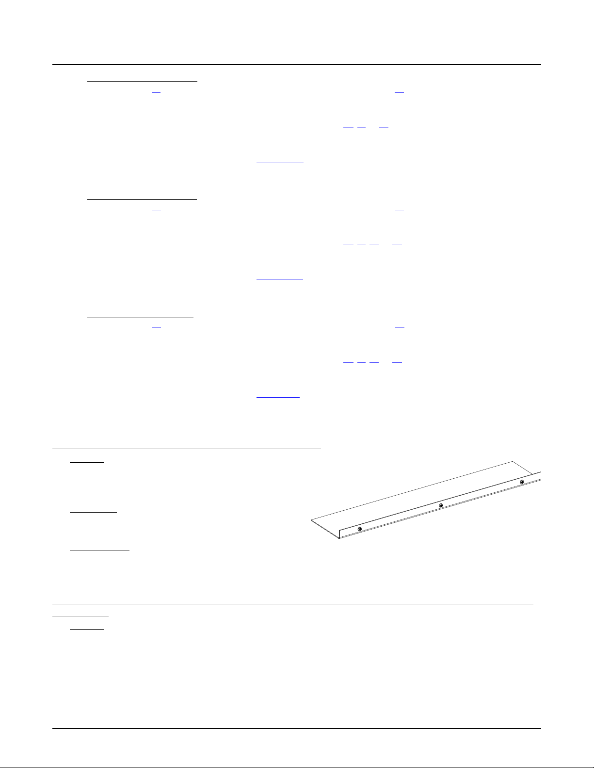
NetSure™ 7100 DC Power System
29
System Application Guide
5) 1R482000e3 Rectifier Option: Order interface components for module mounting assembly(s) Spec. No. 588705300 as
required per List 32. Order field expansion module mounting assembly(s) per List 33. Order module mounting
assembly(s) as required. See “Module Mounting Assembly” starting on page 99 (choices are 58870530001,
58870530003).
a) Order the front access AC Input Termination Assembly per List 40, 41, or 42 if module mounting assembly
58870530001 ordered (or order module mounting assemblies that accommodate AC input cable assemblies or line
cords; 58870530003. See “Module Mounting Assembly” starting on page 99).
b) Order rectifier modules as required, P/N 1R482000e3.
c) Order a module mounting position blank cover panel, P/N SXA1100035/1, for each empty module mounting position
in the system, as desired.
6) 1R483500e3 Rectifier Option: Order interface components for module mounting assembly(s) Spec. No. 588705400 as
required per List 36. Order field expansion module mounting assembly(s) per List 37. Order module mounting
assembly(s) as required. See “Module Mounting Assembly” starting on page 99 (choices are 58870540001,
58870540002, 58870540003, 58870540004).
a) Order the front access AC Input Termination Assembly per List 40, 41, 42, or 43 if module mounting assembly
58870540001 ordered (or order module mounting assemblies that accommodate AC input cable assemblies or line
cords; 58870540002, 58870540003, 58870540004. See “Module Mounting Assembly” starting on page 99).
b) Order rectifier modules as required, P/N 1R483500e3.
c) Order a module mounting position blank cover panel, P/N SXA1100035/1, for each empty module mounting position
in the system, as desired.
7) 1R484000e Rectifier Option: Order interface components for module mounting assembly(s) Spec. No. 588705500 as
required per List 38. Order field expansion module mounting assembly(s) per List 39. Order module mounting
assembly(s) as required. See “Module Mounting Assembly” starting on page 99 (choices are 58870550001,
58870550002, 58870550003, 58870550004, 58870550005).
a) Order the front access AC Input Termination Assembly per List 40, 41, 42, or 43 if module mounting assembly
58870550001ordered (or order module mounting assemblies with AC line cords or terminal blocks; 58870550002,
58870550003, 58870550004, 58870550005). See “Module Mounting Assembly” starting on page 99.)
b) Order rectifier modules as required, P/N 1R484000e.
c) Order a module mounting position blank cover panel, P/N 21140440, for each empty module mounting position in the
system, as desired.
List 4: Distribution Only Bay Distribution Cabinet Bottom Rear Cover
Features
♦ Bottom rear cover shield for use when a supplemental
bay is configured for “distribution only” (no module
mounting assembly).
Restrictions
Module mounting assembly(s) cannot be mounted in a bay
when List 4 is installed.
Ordering Notes
1) Order when a supplemental distribution bay is configured for “distribution only” (no module mounting assembly).
List 5: 2
from Main Bay
nd
through 6th Supplemental Bay Common Equipment (Power and Distribution or Distribution Only), Located Remote
Features
♦ Provides common equipment for one remote “power and distribution or distribution only” bay rated for up to 2000
amperes of distribution. Includes interbay communications cabling. System components factory mounted in a relay rack,
on shipping rails, or in an enclosure as specified when ordered.
♦ Accepts one (1) distribution cabinet (options are 1-row, 2-row, 3-row, or 4-row cabinet).
♦ Includes SM-DU (provides bay interface to the system controller).
Spec. No: 582127000 SAG582127000
Model No: 7100 Revision BJ, August 21, 2020
Page 30

NetSure™ 7100 DC Power System
30
System Application Guide
♦ Accepts up to six (6) module mounting assemblies Spec. No. 588705000 or 588705300 or 588705400 or 588705500
(including expansion assemblies).
Restrictions
System components factory mounted in a relay rack, on shipping rails, or in an enclosure as specified when ordered.
When the system is equipped with a List 40, 41, 42, 43, 45, 46, or 47 front access input termination assembly, refer to the
restrictions under these list descriptions.
Will not accept List 60 converter interface components.
Will not accept dual voltage distribution panels.
Order maximum of five (5) List 5 per Power System.
Interbay power cabling is not included, and must be separately provided per site requirements.
If low voltage disconnect (List LL) is to be included, the Main Bay (List 1) of the system must also have low voltage disconnect
(List LL or List LB).
Optional battery shunt will not read battery current properly (due to cabling to bays tied to battery input termination bars)
and should be disabled. Battery current can be calculated by controller.
Ordering Notes
1) Order a relay rack or shipping brackets per “Relay Racks and Shipping Brackets” on page 110. If required, order relay
rack transition plates per “Transition Plates to Mount Relay Rack on Top of GNB Absolyte IIP Batteries” on page 111. A
relay rack, shipping rails, or enclosure must specified when ordered.
2) Order an enclosure per “Enclosure” on page 112 if desired. A relay rack, shipping rails, or enclosure must specified when
ordered.
3) Order one (1) List 21, 22, 23, or 24 distribution cabinet.
a) Order up to four (4) (per the capacity of the distribution cabinet ordered) distribution panels, battery disconnect
panels, return bar panel, and/or bulk output panel as required per “Single Voltage Distribution Panel”, “Battery
Disconnect Distribution Panel”, “Return Bar Panel”, and “Bulk Output Panel” starting on page 56.
b) Order low voltage disconnect options as required per “Low Voltage Disconnect Options” starting on page 90.
c) Order fuses and/or circuit breakers as required per “Distribution Devices” starting on page 118.
d) Order input and load distribution lugs, lug adapters, and lug hardware kits as required per “Recommended Wire
Sizes, Branch Circuit Protection, Crimp Lugs, and Wiring Illustrations” starting on page 131.
e) Order a DC conduit box as required per List 28.
f) Order a distribution cabinet top shield as required per List 29.
g) If distribution only, order a bottom rear distribution cabinet cover per List 4.
h) Order a battery shunt as required per List 90, 91, or 92.
4) 1R483500e Rectifier Option: Order interface components for module mounting assembly(s) Spec. No. 588705000 as
required per List 30. Order field expansion module mounting assembly(s) per List 31. Order module mounting
assembly(s) as required. See “Module Mounting Assembly” starting on page 99 (choices are 58870500021,
58870500022, 58870500031, 58870500032, 58870500033).
a) Order the front access AC Input Termination Assembly per List 40, 41, 42, or 43 if module mounting assembly
58870500021 ordered (or order module mounting assemblies with AC line cords or terminal blocks; 58870500022,
58870500031, 58870500032, 58870500033. See “Module Mounting Assembly” starting on page 99).
b) Order rectifier modules as required, P/N 1R483500e.
c) Order a module mounting position blank cover panel, P/N 21140440, for each empty module mounting position in the
system, as desired.
5) 1C400483500e Converter Option: Order interface components for module mounting assembly(s) Spec. No. 588705000
as required per List 34. Order field expansion module mounting assembly(s) per List 35. Order module mounting
assembly(s) as required. See “Module Mounting Assembly” starting on page 99 (choices are 58870500040,
58870500041, 58870500042).
a) Order the front access DC Input Termination Assembly per List 45, 46, or 47 if module mounting assembly
58870500040 ordered (or order module mounting assemblies with terminal blocks; 58870500041, 58870500042.
See “Module Mounting Assembly” starting on page 99).
b) Order converter modules as required, P/N 1C400483500e.
c) Order a module mounting position blank cover panel, P/N 21140440, for each empty module mounting position in the
system, as desired.
Spec. No: 582127000 SAG582127000
Model No: 7100 Revision BJ, August 21, 2020
Page 31

NetSure™ 7100 DC Power System
31
System Application Guide
6) 1R482000e3 Rectifier Option: Order interface components for module mounting assembly(s) Spec. No. 588705300 as
required per List 32. Order field expansion module mounting assembly(s) per List 33. Order module mounting
assembly(s) as required. See “Module Mounting Assembly” starting on page 99 (choices are 58870530001,
58870530003).
a) Order the front access AC Input Termination Assembly per List 40, 41, or 42 if module mounting assembly
58870530001 ordered (or order module mounting assemblies that accommodate AC input cable assemblies or line
cords; 58870530003. See “Module Mounting Assembly” starting on page 99).
b) Order rectifier modules as required, P/N 1R482000e3.
c) Order a module mounting position blank cover panel, P/N SXA1100035/1, for each empty module mounting position
in the system, as desired.
7) 1R483500e3 Rectifier Option: Order interface components for module mounting assembly(s) Spec. No. 588705400 as
required per List 36. Order field expansion module mounting assembly(s) per List 37. Order module mounting
assembly(s) as required. See “Module Mounting Assembly” starting on page 99 (choices are 58870540001,
58870540002, 58870540003, 58870540004).
a) Order the front access AC Input Termination Assembly per List 40, 41, 42, or 43 if module mounting assembly
58870540001 ordered (or order module mounting assemblies that accommodate AC input cable assemblies or line
cords; 58870540002, 58870540003, 58870540004. See “Module Mounting Assembly” starting on page 99).
b) Order rectifier modules as required, P/N 1R483500e3.
c) Order a module mounting position blank cover panel, P/N SXA1100035/1, for each empty module mounting position
in the system, as desired.
8) 1R484000e Rectifier Option: Order interface components for module mounting assembly(s) Spec. No. 588705500 as
required per List 38. Order field expansion module mounting assembly(s) per List 39. Order module mounting
assembly(s) as required. See “Module Mounting Assembly” starting on page 99 (choices are 58870550001,
58870550002, 58870550003, 58870550004, 58870550005).
a) Order the front access AC Input Termination Assembly per List 40, 41, 42, or 43 if module mounting assembly
58870550001ordered (or order module mounting assemblies with AC line cords or terminal blocks; 58870550002,
58870550003, 58870550004, 58870550005). See “Module Mounting Assembly” starting on page 99.)
b) Order rectifier modules as required, P/N 1R484000e.
c) Order a module mounting position blank cover panel, P/N 21140440, for each empty module mounting position in the
system, as desired.
9) Order battery trays as required per List 93 or List 95.
a) Order batteries as required per “Batteries” under ACCESSORY DESCRIPTIONS.
b) Order “Optional Battery Tray Battery Disconnect Circuit Breaker and Housing Kits” as required.
c) Order “Optional Battery Tray Front Battery Cover Kits” as required.
List 7: 1
Bay, Enclosure Mounted Option Only
st
Supplemental Bay Common Equipment (Power and Distribution or Distribution Only), Located In-Line with Main
Features
♦ Provides common equipment for one bussed “power and distribution or distribution only” bay rated for up to 2000
amperes of distribution. Includes interbay power busbars and communications cable. System components factory
mounted in an enclosure as specified when ordered.
♦ Mounts to either left or right side of List 1 Main Bay.
♦ Accepts one (1) distribution cabinet (options are 3-row or 4-row cabinet).
♦ Includes SM-DU (provides bay interface to the system controller).
♦ Accepts up to six (6) module mounting assemblies Spec. No. 588705000 or 588705400 or 588705500 (including
expansion assemblies).
♦ Includes enclosure joining kit P/N 563677.
Restrictions
System components factory mounted in an enclosure as specified when ordered.
Cannot put List 7 system next to a system in a relay rack.
When the system is equipped with a List 40, 41, 42, or 43 front access input termination assembly, refer to the restrictions
under these list descriptions.
Spec. No: 582127000 SAG582127000
Model No: 7100 Revision BJ, August 21, 2020
Page 32

NetSure™ 7100 DC Power System
32
System Application Guide
Will not accept List 21 and 22 distribution cabinet.
(List 21 and 22 are not provided with connection points for interbay busbars.)
Will not accept List 93 and List 95 battery trays option.
Rear access required for installation of inter-bay busbars.
If low voltage disconnect (List LL) is to be included, the Main Bay (List 1) of the system must also have low voltage disconnect
(List LL or List LB).
Ordering Notes
1) Order an enclosure and enclosure options per “Enclosure” on page 112.
2) Order one (1) List 23 or 24 distribution cabinet.
a) Order up to four (4) (per the capacity of the distribution cabinet ordered) distribution panels, battery disconnect
panels, return bar panel, and/or bulk output panel as required per “Single Voltage Distribution Panel”, “Battery
Disconnect Distribution Panel”, “Return Bar Panel”, and “Bulk Output Panel” starting on page 56.
b) Order low voltage disconnect options as required per “Low Voltage Disconnect Options” starting on page 90.
c) Order fuses and/or circuit breakers as required per “Distribution Devices” starting on page 118.
d) Order input and load distribution lugs, lug adapters, and lug hardware kits as required per “Recommended Wire
Sizes, Branch Circuit Protection, Crimp Lugs, and Wiring Illustrations” starting on page 131.
e) Order a battery shunt as required per List 90, 91, or 92.
3) 1R483500e Rectifier Option: Order interface components for module mounting assembly(s) Spec. No. 588705000 as
required per List 30. Order field expansion module mounting assembly(s) per List 31. Order module mounting
assembly(s) as required. See “Module Mounting Assembly” starting on page 99 (choices are 58870500021,
58870500022, 58870500031, 58870500032, 58870500033).
a) Order the front access AC Input Termination Assembly per List 40, 41, 42, or 43 if module mounting assembly
58870500021 ordered (or order module mounting assemblies with AC line cords or terminal blocks; 58870500022,
58870500031, 58870500032, 58870500033. See “Module Mounting Assembly” starting on page 99).
b) Order rectifier modules as required, P/N 1R483500e.
c) Order a module mounting position blank cover panel, P/N 21140440, for each empty module mounting position in the
system, as desired.
4) 1R483500e3 Rectifier Option: Order interface components for module mounting assembly(s) Spec. No. 588705400 as
required per List 36. Order field expansion module mounting assembly(s) per List 37. Order module mounting
assembly(s) as required. See “Module Mounting Assembly” starting on page 99 (choices are 58870540001,
58870540002, 58870540003, 58870540004).
a) Order the front access AC Input Termination Assembly per List 40, 41, 42, or 43 if module mounting assembly
58870540001 ordered (or order module mounting assemblies that accommodate AC input cable assemblies or line
cords; 58870540002, 58870540003, 58870540004. See “Module Mounting Assembly” starting on page 99).
b) Order rectifier modules as required, P/N 1R483500e3.
c) Order a module mounting position blank cover panel, P/N SXA1100035/1, for each empty module mounting position
in the system, as desired.
5) 1R484000e Rectifier Option: Order interface components for module mounting assembly(s) Spec. No. 588705500 as
required per List 38. Order field expansion module mounting assembly(s) per List 39. Order module mounting
assembly(s) as required. See “Module Mounting Assembly” starting on page 99 (choices are 58870550001,
58870550002, 58870550003, 58870550004, 58870550005).
a) Order the front access AC Input Termination Assembly per List 40, 41, 42, or 43 if module mounting assembly
58870550001ordered (or order module mounting assemblies with AC line cords or terminal blocks; 58870550002,
58870550003, 58870550004, 58870550005). See “Module Mounting Assembly” starting on page 99.)
b) Order rectifier modules as required, P/N 1R484000e.
c) Order a module mounting position blank cover panel, P/N 21140440, for each empty module mounting position in the
system, as desired.
Spec. No: 582127000 SAG582127000
Model No: 7100 Revision BJ, August 21, 2020
Page 33

NetSure™ 7100 DC Power System
33
System Application Guide
List 8: 3rd through 6th Supplemental Bay Common Equipment (Power and Distribution or Distribution Only), Located In-Line
with Main Bay, Enclosure Mounted Option Only
Features
♦ Provides common equipment for one bussed “power and distribution or distribution only” bay rated for up to 2000
amperes of distribution. Includes interbay power busbars and communications cable. System components factory
mounted in an enclosure as specified when ordered.
♦ Mounts to either left or right side of List 2 Supplemental Bay.
♦ Accepts one (1) distribution cabinet (options are 3-row or 4-row cabinet).
♦ Includes SM-DU (provides bay interface to the system controller).
♦ Accepts up to six (6) module mounting assemblies Spec. No. 588705000 or 588705400 or 588705500 (including
expansion assemblies).
♦ Includes enclosure joining kit P/N 563677.
Restrictions
System components factory mounted in an enclosure as specified when ordered.
Cannot put List 8 system next to a system in a relay rack.
When the system is equipped with a List 40, 41, 42, or 43 front access input termination assembly, refer to the restrictions
under these list descriptions.
Will not accept List 21 and 22 distribution cabinet.
(List 21 and 22 are not provided with connection points for interbay busbars.)
Will not accept List 93 and List 95 battery tray option.
Rear access required for installation of inter-bay busbars.
If low voltage disconnect (List LL) is to be included, the Main Bay (List 1) of the system must also have low voltage disconnect
(List LL or List LB).
Ordering Notes
1) Order an enclosure and enclosure options per “Enclosure” on page 112.
2) Order one (1) List 23 or 24 distribution cabinet.
a) Order up to four (4) (per the capacity of the distribution cabinet ordered) distribution panels, battery disconnect
panels, return bar panel, and/or bulk output panel as required per “Single Voltage Distribution Panel”, “Battery
Disconnect Distribution Panel”, “Return Bar Panel”, and “Bulk Output Panel” starting on page 56.
b) Order battery disconnect contactors and low voltage disconnect options as required per “Battery Disconnect
Contactors” and “Low Voltage Disconnect Options” starting on page 89.
c) Order fuses and/or circuit breakers as required per “Distribution Devices” starting on page 118.
d) Order input and load distribution lugs, lug adapters, and lug hardware kits as required per “Recommended Wire
Sizes, Branch Circuit Protection, Crimp Lugs, and Wiring Illustrations” starting on page 131.
e) Order a battery shunt as required per List 90, 91, or 92.
3) 1R483500e Rectifier Option: Order interface components for module mounting assembly(s) Spec. No. 588705000 as
required per List 30. Order field expansion module mounting assembly(s) per List 31. Order module mounting
assembly(s) as required. See “Module Mounting Assembly” starting on page 99 (choices are 58870500021,
58870500022, 58870500031, 58870500032, 58870500033).
a) Order the front access AC Input Termination Assembly per List 40, 41, 42, or 43 if module mounting assembly
58870500021 ordered (or order module mounting assemblies with AC line cords or terminal blocks; 58870500022,
58870500031, 58870500032, 58870500033. See “Module Mounting Assembly” starting on page 99).
b) Order rectifier modules as required, P/N 1R483500e.
c) Order a module mounting position blank cover panel, P/N 21140440, for each empty module mounting position in the
system, as desired.
4) 1R483500e3 Rectifier Option: Order interface components for module mounting assembly(s) Spec. No. 588705400 as
required per List 36. Order field expansion module mounting assembly(s) per List 37. Order module mounting
assembly(s) as required. See “Module Mounting Assembly” starting on page 99 (choices are 58870540001,
58870540002, 58870540003, 58870540004).
a) Order the front access AC Input Termination Assembly per List 40, 41, 42, or 43 if module mounting assembly
58870540001 ordered (or order module mounting assemblies that accommodate AC input cable assemblies or line
cords; 58870540002, 58870540003, 58870540004. See “Module Mounting Assembly” starting on page 99).
Spec. No: 582127000 SAG582127000
Model No: 7100 Revision BJ, August 21, 2020
Page 34

NetSure™ 7100 DC Power System
34
System Application Guide
b) Order rectifier modules as required, P/N 1R483500e3.
c) Order a module mounting position blank cover panel, P/N SXA1100035/1, for each empty module mounting position
in the system, as desired.
5) 1R484000e Rectifier Option: Order interface components for module mounting assembly(s) Spec. No. 588705500 as
required per List 38. Order field expansion module mounting assembly(s) per List 39. Order module mounting
assembly(s) as required. See “Module Mounting Assembly” starting on page 99 (choices are 58870550001,
58870550002, 58870550003, 58870550004, 58870550005).
a) Order the front access AC Input Termination Assembly per List 40, 41, 42, or 43 if module mounting assembly
58870550001ordered (or order module mounting assemblies with AC line cords or terminal blocks; 58870550002,
58870550003, 58870550004, 58870550005). See “Module Mounting Assembly” starting on page 99.)
b) Order rectifier modules as required, P/N 1R484000e.
c) Order a module mounting position blank cover panel, P/N 21140440, for each empty module mounting position in the
system, as desired.
Spec. No: 582127000 SAG582127000
Model No: 7100 Revision BJ, August 21, 2020
Page 35
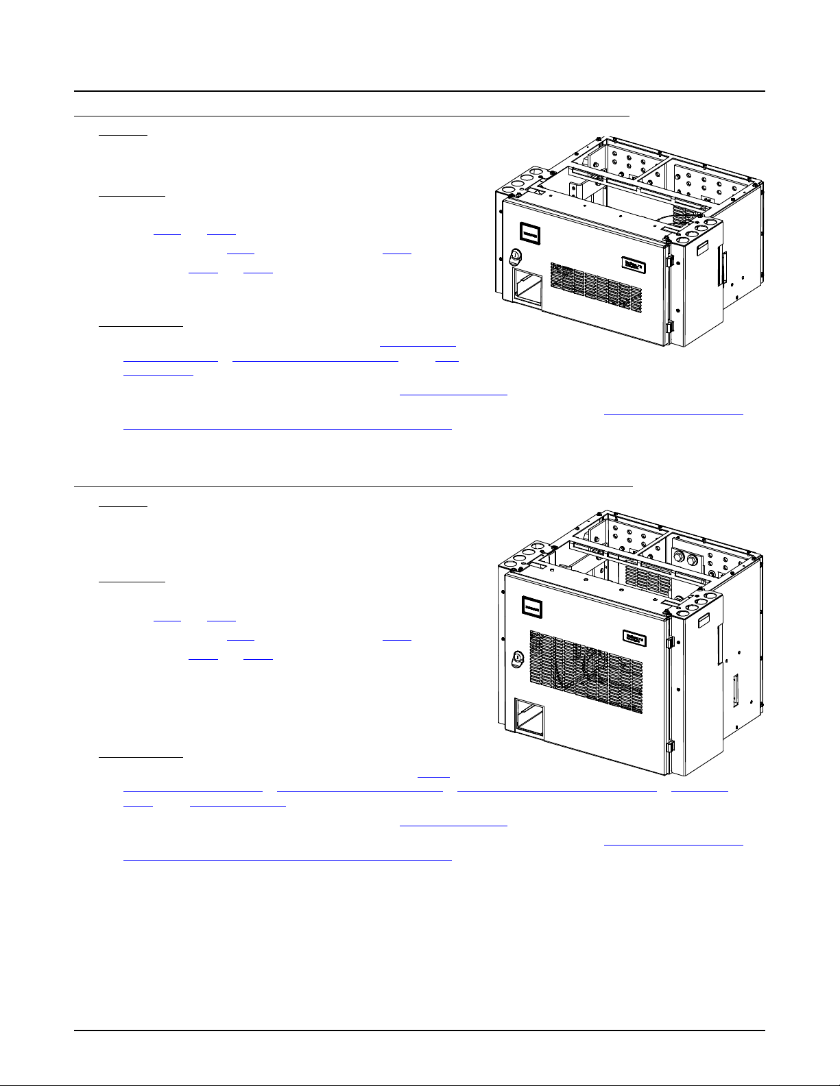
NetSure™ 7100 DC Power System
35
System Application Guide
List 21: One-Row Distribution Cabinet, For System Mounted in a Relay Rack or on Shipping Rails Only
Features
♦ Accepts one (1) distribution panel.
♦ Rated for up to 600 amperes of distribution.
Restrictions
System mounted in a relay rack or on shipping rails only.
For use in List 1 and List 5 bays.
Cannot be ordered with List 1 if it is to be used with a List 2.
Not available for List 2 and List 3 bays (no interbay busbar landings
available).
Battery disconnect panels cannot be ordered for use in a List 21.
Ordering Notes
1) Order one (1) distribution panel as required per “Single Voltage
Distribution Panel”, “Dual Voltage Distribution Panel”, and “Bulk
Output Panel” starting on page 56.
2) Order fuses and/or circuit breakers as required per “Distribution Devices” starting on page 118.
3) Order input and load distribution lugs, lug adapters, and lug hardware kits as required per “Recommended Wire Sizes,
Branch Circuit Protection, Crimp Lugs, and Wiring Illustrations” starting on page 131.
4) Order battery contactor, battery shunt, and low voltage disconnect options as required.
List 22: Two-Row Distribution Cabinet, For System Mounted in a Relay Rack or on Shipping Rails Only
Features
♦ Accepts up to two (2) total distribution panels, battery disconnect
distribution panels, and/or return bar panel.
♦ Rated for up to 1200 amperes of distribution.
Restrictions
System mounted in a relay rack or on shipping rails only.
For use in List 1 and List 5 bays.
Cannot be ordered with List 1 if it is to be used with a List 2.
Not available for List 2 and List 3 bays (no interbay busbar landings
available).
The List LL Low Voltage Load Disconnect (LVLD) option cannot be
installed in the field for systems that are not equipped with any LVLD’s
from the factory. Field replacement of factory installed LVLD contactors
is still available.
Ordering Notes
1) Order up to two (2) distribution panels as required per “Single
Voltage Distribution Panel”, “Dual Voltage Distribution Panel”, “Battery Disconnect Distribution Panel”, “Return Bar
Panel”, and “Bulk Output Panel” starting on page 56.
2) Order fuses and/or circuit breakers as required per “Distribution Devices” starting on page 118.
3) Order input and load distribution lugs, lug adapters, and lug hardware kits as required per “Recommended Wire Sizes,
Branch Circuit Protection, Crimp Lugs, and Wiring Illustrations” starting on page 131.
4) Order battery contactor, battery shunt, and low voltage disconnect options as required.
Spec. No: 582127000 SAG582127000
Model No: 7100 Revision BJ, August 21, 2020
Page 36
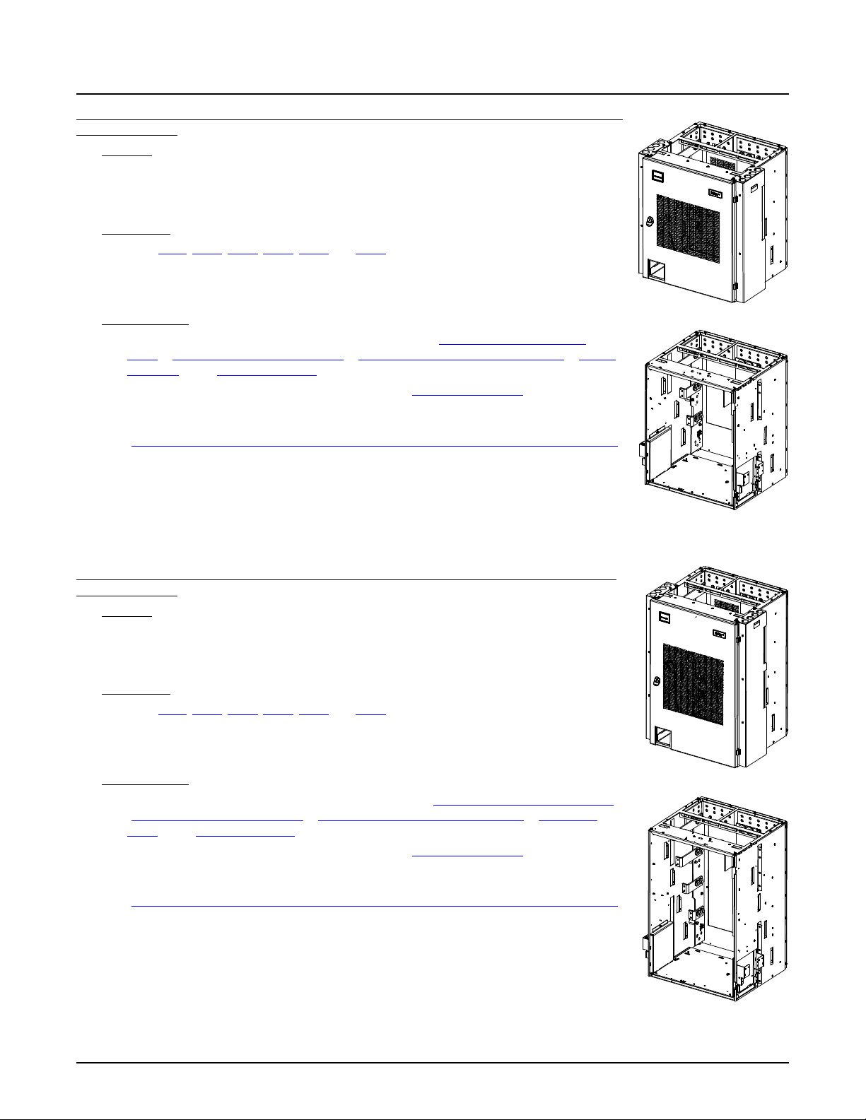
NetSure™ 7100 DC Power System
36
Relay Rack Installation
Cabinet Installation
Relay Rack Installation
Cabinet Installation
System Application Guide
List 23: Three-Row Distribution Cabinet, For System Mounted in a Relay Rack, on Shipping Rails,
or in an Enclosure
List 24: Four-Row Distribution Cabinet, For System Mounted in a Relay Rack, on Shipping Rails,
or in an Enclosure
Features
♦ Accepts up to three (3) total distribution panels, battery disconnect distribution panels,
and/or return bar panel.
♦ Rated for up to 1800 amperes of distribution.
Restrictions
For use in List 1, List 2, List 3, List 5, List 7 and List 8.
The List LL Low Voltage Load Disconnect (LVLD) option cannot be installed in the field for
systems that are not equipped with any LVLD’s from the factory. Field replacement of factory
installed LVLD contactors is still available.
Ordering Notes
1) Order up to three (3) distribution panels as required per “Single Voltage Distribution
Panel”, “Dual Voltage Distribution Panel”, “Battery Disconnect Distribution Panel”, “Return
Bar Panel”, and “Bulk Output Panel” starting on page 56.
2) Order fuses and/or circuit breakers as required per “Distribution Devices” starting on page
118.
3) Order input and load distribution lugs, lug adapters, and lug hardware kits as required per
“Recommended Wire Sizes, Branch Circuit Protection, Crimp Lugs, and Wiring Illustrations”
starting on page 131.
4) Order battery contactor, battery shunt, and low voltage disconnect options as required.
Features
♦ Accepts up to four (4) total distribution panels, battery disconnect distribution panels,
and/or return bar panel.
♦ Rated for up to 2000 amperes of distribution.
Restrictions
For use in List 1, List 2, List 3, List 5, List 7 and List 8.
The List LL Low Voltage Load Disconnect (LVLD) option cannot be installed in the field for
systems that are not equipped with any LVLD’s from the factory. Field replacement of factory
installed LVLD contactors is still available.
Ordering Notes
1) Order up to four (4) distribution panels as required per “Single Voltage Distribution Panel”,
“Dual Voltage Distribution Panel”, “Battery Disconnect Distribution Panel”, “Return Bar
Panel”, and “Bulk Output Panel” starting on page 56.
2) Order fuses and/or circuit breakers as required per “Distribution Devices” starting on page
118.
3) Order input and load distribution lugs, lug adapters, and lug hardware kits as required per
“Recommended Wire Sizes, Branch Circuit Protection, Crimp Lugs, and Wiring Illustrations”
starting on page 131.
4) Order battery contactor, battery shunt, and low voltage disconnect options as required.
Spec. No: 582127000 SAG582127000
Model No: 7100 Revision BJ, August 21, 2020
Page 37
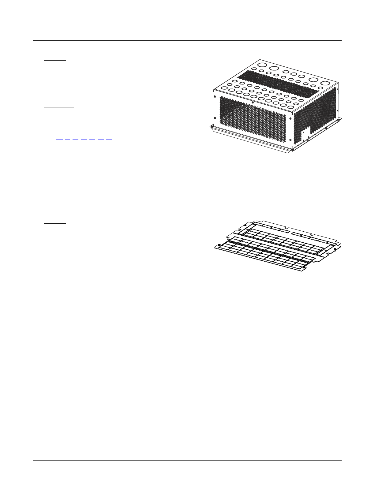
NetSure™ 7100 DC Power System
37
System Application Guide
List 28: DC Conduit Box, For System Mounted in a Relay Rack Only
Features
♦ Provides a metal box on top of the DC distribution cabinet so
that all DC load cabling and battery cabling can be routed
through conduit.
Note:
List 28 DC conduit box is mounted on top of the
distribution cabinet underneath the relay rack’s top brace.
Restrictions
Not for use with systems mounted in an enclosure.
Factory installed on top of bay.
Cannot be used with front access AC or DC termination assemblies
(List 40, 41, 42, 43, 45, 46, 47).
The maximum current through the distribution cabinet is 600A and
the maximum current through a single distribution panel is 400A.
Only available for use with bullet distribution panels installed in distribution cabinet.
CANNOT be used when either load or battery LVD is installed in distribution cabinet.
CANNOT be used with List 21 (one row distribution cabinet).
Ordering Notes
1) Order as required.
List 29: Top Shield for Distribution Cabinet, For System Mounted in a Relay Rack Only
Features
♦ Plastic shield covers all wiring access openings in top of
distribution cabinet. Individual cutouts can be removed for
wiring as required for specific installation.
Restrictions
Not for use with systems mounted in an enclosure.
Ordering Notes
1) Where closed top cover is required, order one (1) List 29 for each List 21, 22, 23, and 24 ordered.
Spec. No: 582127000 SAG582127000
Model No: 7100 Revision BJ, August 21, 2020
Page 38
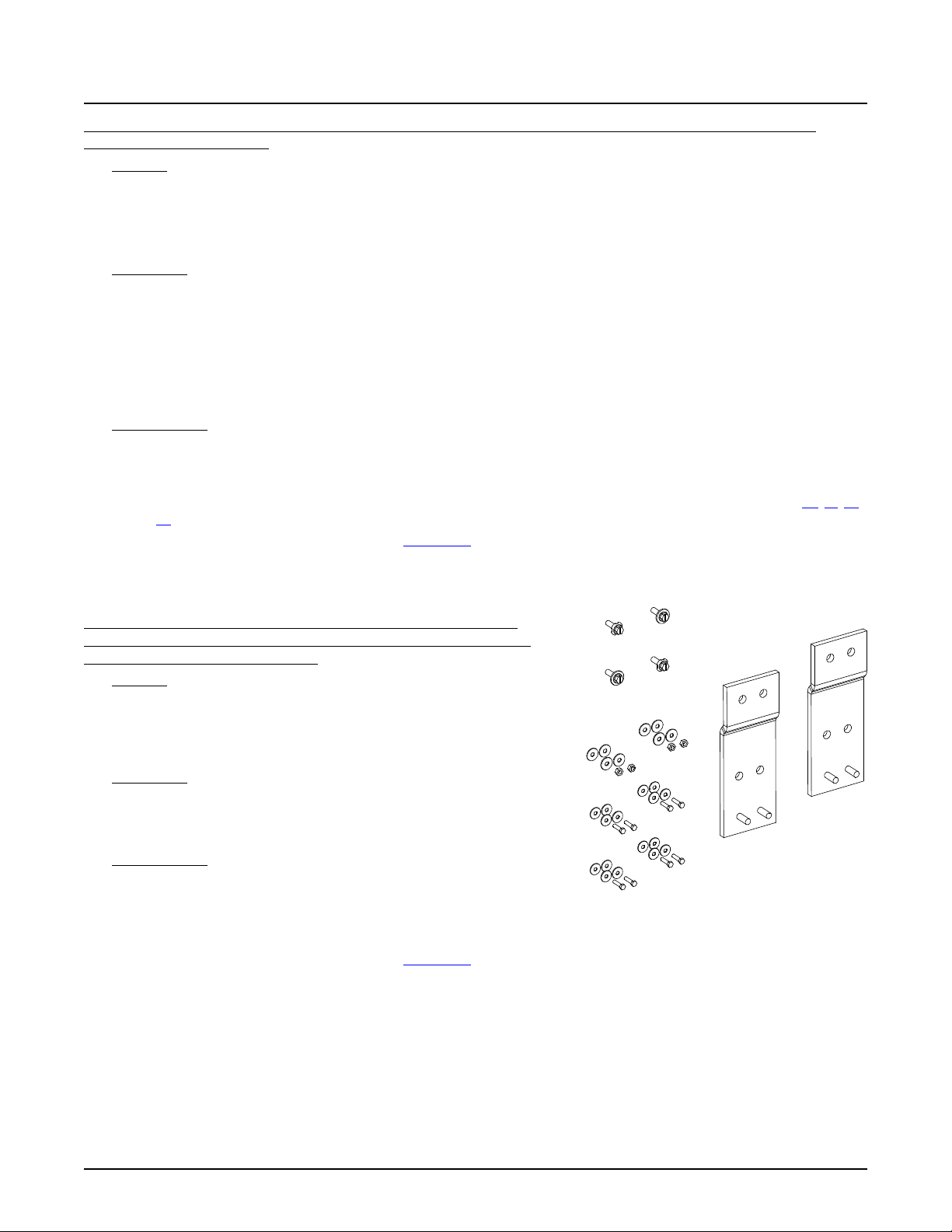
NetSure™ 7100 DC Power System
38
Shelf Mounting Hardware
Busbar Mounting Hardware
Interconnecting Busbars
System Application Guide
List 30: Module Mounting Assembly Interface Components (for Spec. No. 58870500021, 58870500022, 58870500031,
58870500032, 58870500033)
List 31: Module Mounting Assembly Field Expansion Kit (for Spec. No.
58870500022, 58870500031, 58870500032, 58870500033), For System
Mounted in a Relay Rack or Enclosure
Features
♦ Provides components to add one (1) to five (5) (relay rack mounted option) or one (1) to six (6) (enclosure mounted
option) module mounting assembly(s) (Spec. No. 58870500021, 58870500022, 58870500031, 58870500032,
58870500033) to a Main or Supplemental Bay.
♦ Refer to “Module Mounting Assembly” starting on page 99 for module mounting assembly information.
Restrictions
Includes 'module mounting assembly-to-power system/distribution cabinet' interconnect components only. The module
mounting assembly(s) must be ordered separately (choices are 58870500021, 58870500022, 58870500031, 58870500032,
58870500033).
Relay Rack Mounted Option: Each bay (when used with a List 40, 41, 42 or 43) can be equipped with a maximum of five (5)
module mounting assemblies (see List 31 for expansion assemblies).
Enclosure Mounted Option: Each bay (when used with a List 40, 41, 42 or 43) can be equipped with a maximum of six (6)
module mounting assemblies (see List 31 for expansion assemblies).
Ordering Notes
1) Order one (1) List 30 per module mounting assembly(s) Spec. No. 588705000 to be installed in the bay with these
interconnect components and specify the number of rows in the distribution cabinet so correct busbars can be provided.
2) Order module mounting assembly(s) as required. See “Module Mounting Assembly” starting on page 99 (choices are
58870500021, 58870500022, 58870500031, 58870500032, 58870500033). (58870500021 required when List 40, 41, 42
or 43 ordered with the system.)
3) Order rectifier modules as required per P/N 1R483500e.
4) Order a module mounting position blank cover panel, P/N 21140440, for each empty module mounting position in the
system, as desired.
Features
♦ Provides busbars and mounting hardware to tie the DC output busbars
in a field installed module mounting assembly Spec. No. 58870500022,
58870500031, 58870500032, 58870500033 to the system’s DC
busbars or between two (2) module expansion assemblies.
Restrictions
Maximum of two (2) List 31 per bay (total number of shelves in a bay cannot
exceed six, maximum of ten shelves (60 rectifiers) per multi-bay system).
AC inputs MUST be wired directly to the expansion assembly(s).
Ordering Notes
1) Order List 31 for a module mounting assembly Spec. No. 588705000 to
be added in the field.
2) Order a module mounting assembly as required. See “Module
Mounting Assembly” starting on page 99 (choices are 58870500022, 58870500031, 58870500032, 58870500033).
3) Order rectifier modules as required per P/N 1R483500e.
4) Order a module mounting position blank cover panel, P/N 21140440, for each empty module mounting position in the
system, as desired.
Spec. No: 582127000 SAG582127000
Model No: 7100 Revision BJ, August 21, 2020
Page 39
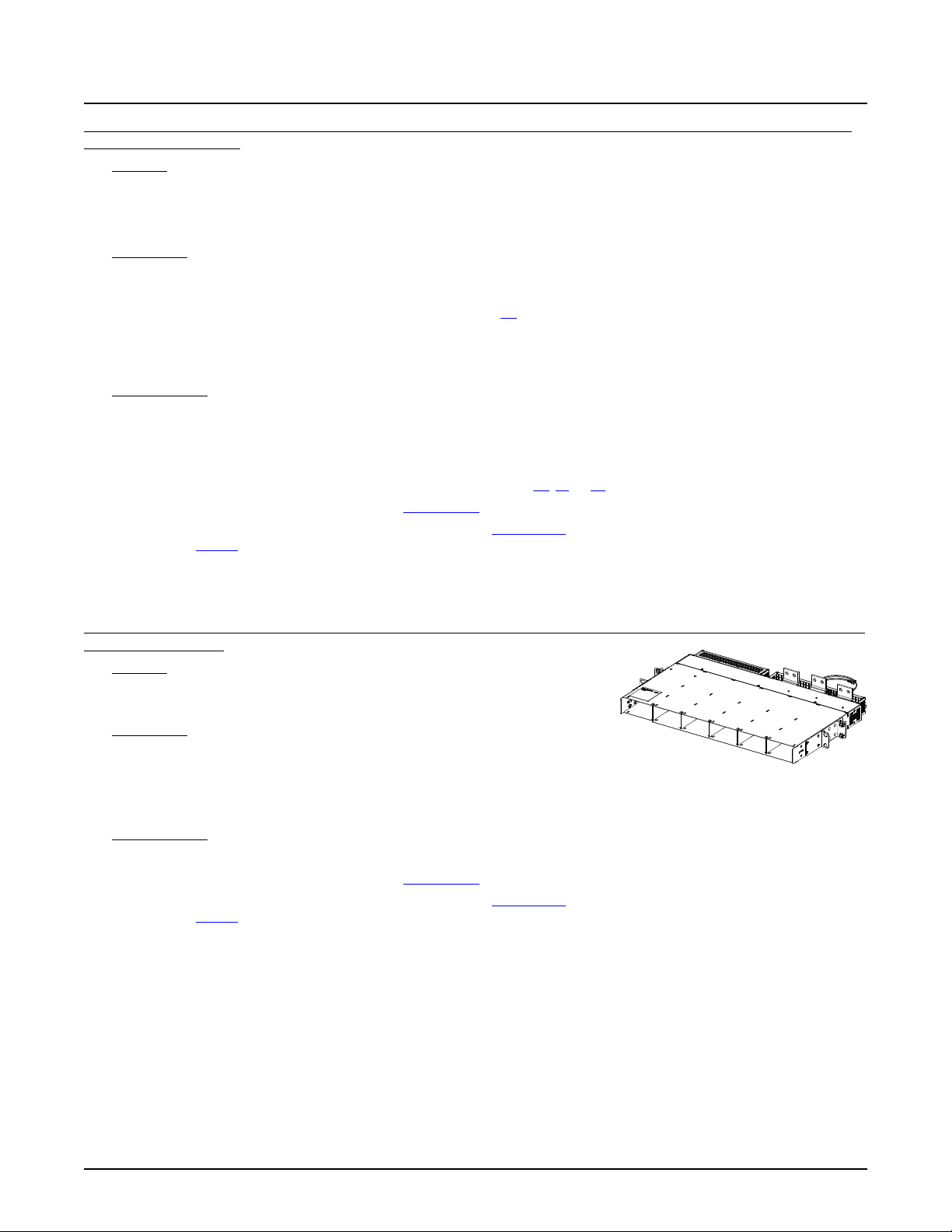
NetSure™ 7100 DC Power System
39
System Application Guide
List 32: Module Mounting Assembly Interface Components (for Spec. No. 588705300), For System Mounted in a Relay Rack
or on Shipping Rails Only
Features
♦ Provides components to add one (1) to five (5) module mounting assembly(s) (Spec. No. 588705300) to a Main or
Supplemental Bay.
♦ Refer to “Module Mounting Assembly” starting on page 99 for module mounting assembly information.
Restrictions
Not for use with systems mounted in an enclosure.
Includes 'module mounting assembly-to-power system/distribution cabinet' interconnect components only. The module
mounting assembly(s) must be ordered separately. Refer to List 60 if converters are to be used in the module mounting
assembly (main bay only).
Each bay (when used with a List 40, 41, or 42) can be equipped with a maximum of five (5) module mounting assemblies (see
List 33 for expansion assemblies).
Ordering Notes
1) Order one (1) List 32 per module mounting assembly(s) Spec. No. 588705300 to be installed in the bay with these
interconnect components (one to five) and specify the number of rows in the distribution cabinet so correct busbars can
be provided.
2) Order module mounting assembly(s) as required. See “Module Mounting Assembly” starting on page 99 (choices are
58870530001, 58870530003). (58870530001 required when List 40, 41, or 42 ordered with the system.)
3) Order rectifier modules as required per P/N 1R482000e3.
4) Order optional DC-DC converter modules as required, P/N 1C48241500 (Main Bay Only).
Requires List 60 to be installed in Main Bay.
5) Order a module mounting position blank cover panel, P/N SXA1100035/1, for each empty module mounting position in the
system, as desired.
List 33: Module Mounting Assembly Field Expansion Kit (for Spec. No. 58870530003), For System Mounted in a Relay Rack or
on Shipping Rails Only
Features
♦ Provides a field expansion module mounting assembly Spec. No.
58870530003.
Restrictions
Not for use with systems mounted in an enclosure.
Maximum of two (2) List 33 per bay (total number of shelves in a bay cannot exceed six, maximum of ten shelves (60 total
rectifiers plus converters) per multi-bay system).
AC inputs MUST be wired directly to the expansion assembly(s).
Ordering Notes
1) Order List 33 for a module mounting assembly Spec. No. 58870530003 to be added in the field.
2) Order rectifier modules as required per P/N 1R482000e3.
3) Order optional DC-DC converter modules as required, P/N 1C48241500 (Main Bay Only).
Requires List 60 to be installed in Main Bay.
4) Order a module mounting position blank cover panel, P/N SXA1100035/1, for each empty module mounting position in the
system, as desired.
5) Order Rectifier AC Input Cable Assemblies per “588705300 and 588705400 Module Mounting Assembly Rectifier AC
Input Cable Assemblies” on page 106 or order Rectifier AC Input Line Cords per “588705300 and 588705400 Module
Mounting Assembly Rectifier AC Input Line Cords” on page 107.
Spec. No: 582127000 SAG582127000
Model No: 7100 Revision BJ, August 21, 2020
Page 40
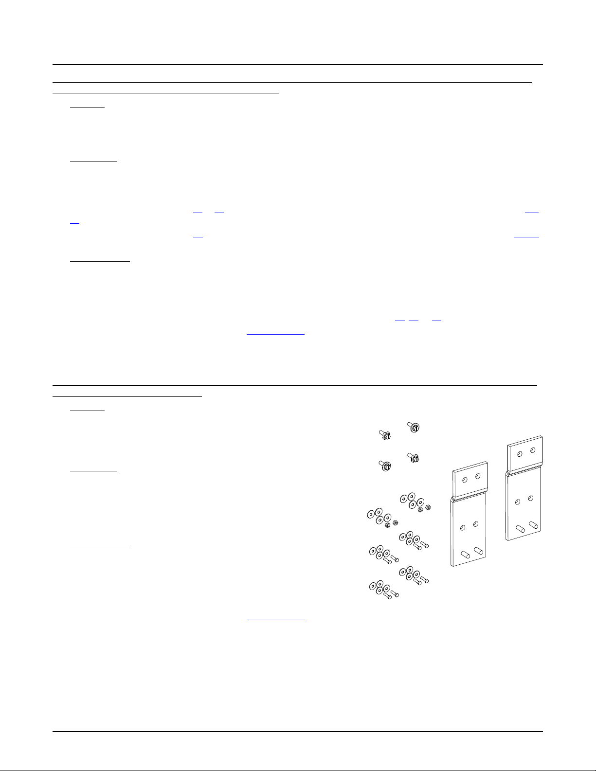
NetSure™ 7100 DC Power System
40
Shelf Mounting Hardware
Busbar Mounting Hardware
Interconnecting Busbars
System Application Guide
List 34: Module Mounting Assembly Interface Components (for Spec. No. 58870500040, 58870500041, 58870500042), For
System Mounted in a Relay Rack or on Shipping Rails Only
List 35: Module Mounting Assembly Field Expansion Kit (for Spec. No. 58870500041, 58870500042), For System Mounted in
a Relay Rack or on Shipping Rails Only
Features
♦ Provides components to add one (1) to five (5) module mounting assembly(s) (Spec. No. 58870500040, 58870500041,
58870500042) to a Main or Supplemental Bay.
♦ Refer to “Module Mounting Assembly” starting on page 99 for module mounting assembly information.
Restrictions
Not for use with systems mounted in an enclosure.
Includes 'module mounting assembly-to-power system/distribution cabinet' interconnect components only. The module
mounting assembly(s) must be ordered separately (choices are 58870500040, 58870500041, 58870500042).
Each bay (when used with a List 45 or 47) can be equipped with a maximum of five (5) module mounting assemblies (see List
35 for expansion assemblies).
Each bay (when used with a List 46) can be equipped with either two (2) or four (4) module mounting assemblies (see List 35
for expansion assemblies).
Ordering Notes
1) Order one (1) List 34 per module mounting assembly(s) Spec. No. 588705000 to be installed in the bay with these
interconnect components (one to five) and specify the number of rows in the distribution cabinet so correct busbars can
be provided.
2) Order module mounting assembly(s) as required. See “Module Mounting Assembly” starting on page 99 (choices are
58870500040, 58870500041, 58870500042). (58870500040 required when List 45, 46, or 47 ordered with the system.)
3) Order converter modules as required, P/N 1C400483500e.
4) Order a module mounting position blank cover panel, P/N 21140440, for each empty module mounting position in the
system, as desired.
Features
♦ Provides busbars and mounting hardware to tie the DC output busbars
in a field installed module mounting assembly Spec. No. 58870500041,
58870500042 to the system’s DC busbars or between two (2) module
expansion assemblies.
Restrictions
Not for use with systems mounted in an enclosure.
Maximum of two (2) List 35 per bay (total number of shelves in a bay
cannot exceed six, maximum of ten shelves (60 converters) per multi-bay
system).
DC inputs MUST be wired directly to the expansion assembly(s).
Ordering Notes
1) Order List 35 for a module mounting assembly Spec. No. 588705000 to
be added in the field.
2) Order a module mounting assembly as required. See “Module
Mounting Assembly” starting on page 99 (choices are 58870500041,
58870500042).
3) Order converter modules as required, P/N 1C400483500e.
4) Order a module mounting position blank cover panel, P/N 21140440, for each empty module mounting position in the
system, as desired.
Spec. No: 582127000 SAG582127000
Model No: 7100 Revision BJ, August 21, 2020
Page 41
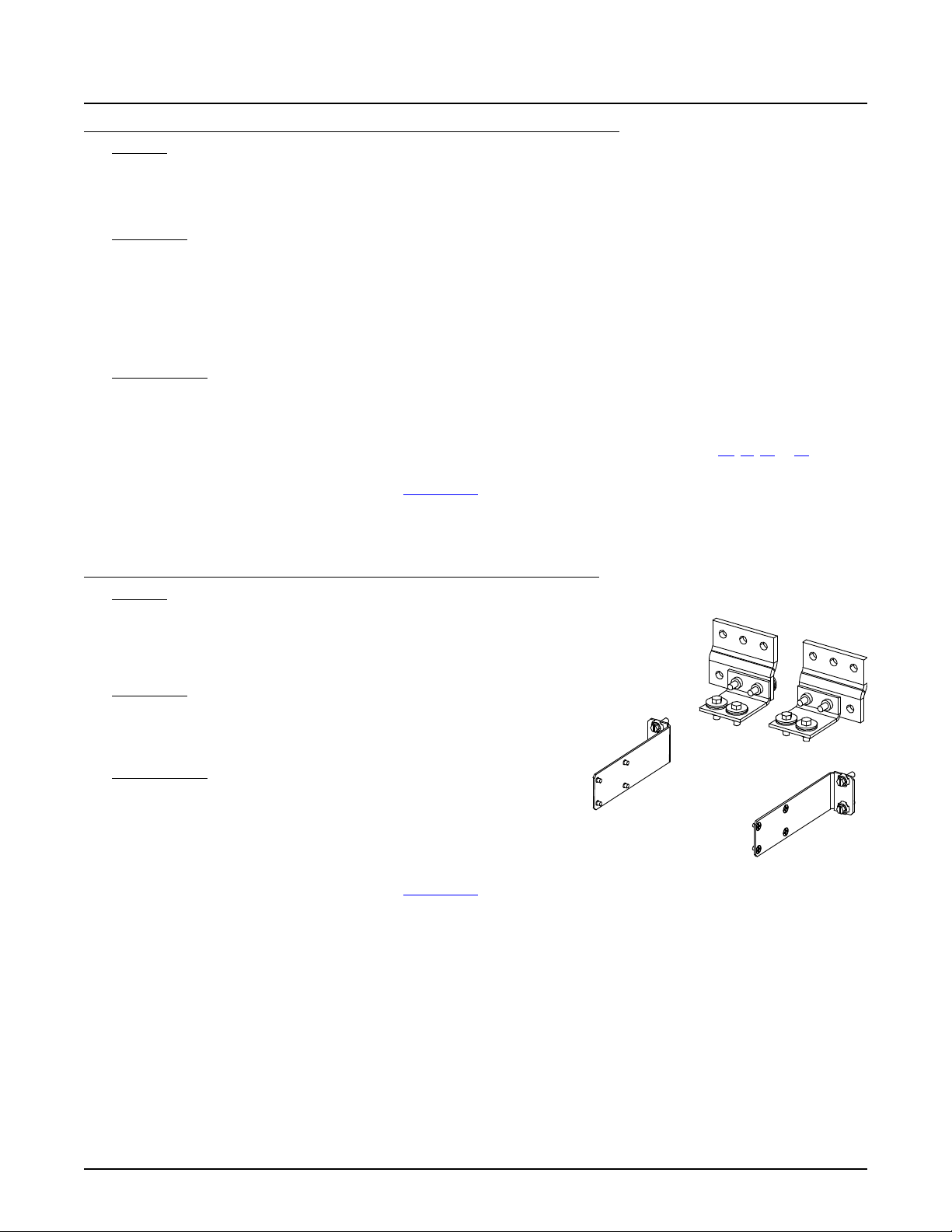
NetSure™ 7100 DC Power System
41
System Application Guide
List 36: Module Mounting Assembly Interface Components (for Spec. No. 588705400)
Features
♦ Provides components to add one (1) to five (5) (relay rack mounted option) or one (1) to six (6) (enclosure mounted
option) module mounting assembly(s) (Spec. No. 588705400) to a Main or Supplemental Bay.
♦ Refer to “Module Mounting Assembly” starting on page 99 for module mounting assembly information.
Restrictions
Includes 'module mounting assembly-to-power system/distribution cabinet' interconnect components only. The module
mounting assembly(s) must be ordered separately.
Relay Rack Mounted Option: Each bay (when used with a List 40, 41, 42 or 43) can be equipped with a maximum of five (5)
module mounting assemblies (see List 37 for expansion assemblies).
Enclosure Mounted Option: Each bay (when used with a List 40, 41, 42 or 43) can be equipped with a maximum of six (6)
module mounting assemblies (see List 37 for expansion assemblies).
Ordering Notes
1) Order one (1) List 36 per module mounting assembly(s) Spec. No. 588705400 to be installed in the bay with these
interconnect components and specify the number of rows in the distribution cabinet so correct busbars can be provided.
2) Order module mounting assembly(s) as required. See “Module Mounting Assembly” starting on page 99 (choices are
58870540001, 58870540002, 58870540003, 58870540004). (58870540001 required when List 40, 41, 42 or 43 ordered
with the system.)
3) Order rectifier modules as required per P/N 1R483500e3.
4) Order a module mounting position blank cover panel, P/N SXA1100035/1, for each empty module mounting position in the
system, as desired.
List 37: Module Mounting Assembly Field Expansion Kit (for Spec. No. 588705400)
Features
♦ Provides busbars and mounting hardware to tie the DC output busbars
in a field installed module mounting assembly Spec. No. 588705400 to
the system’s DC busbars or between two (2) module expansion
assemblies.
Restrictions
Maximum of two (2) List 37 per bay (total number of shelves in a bay cannot
exceed six, maximum of ten shelves (60 rectifiers) per multi-bay system).
AC inputs MUST be wired directly to the expansion assembly(s).
Ordering Notes
1) Order List 37 for a module mounting assembly Spec. No. 588705400 to
be added in the field.
2) Order a module mounting assembly as required. See “Module Mounting
Assembly” starting on page 99 (choices are 58870540002,
58870540003, 58870540004).
3) Order rectifier modules as required per P/N 1R483500e3.
4) Order a module mounting position blank cover panel, P/N SXA1100035/1, for each empty module mounting position in the
system, as desired.
5) Order Rectifier AC Input Cable Assemblies per “588705300 and 588705400 Module Mounting Assembly Rectifier AC
Input Cable Assemblies” on page 106 or order Rectifier AC Input Line Cords per “588705300 and 588705400 Module
Mounting Assembly Rectifier AC Input Line Cords” on page 107.
Spec. No: 582127000 SAG582127000
Model No: 7100 Revision BJ, August 21, 2020
Page 42
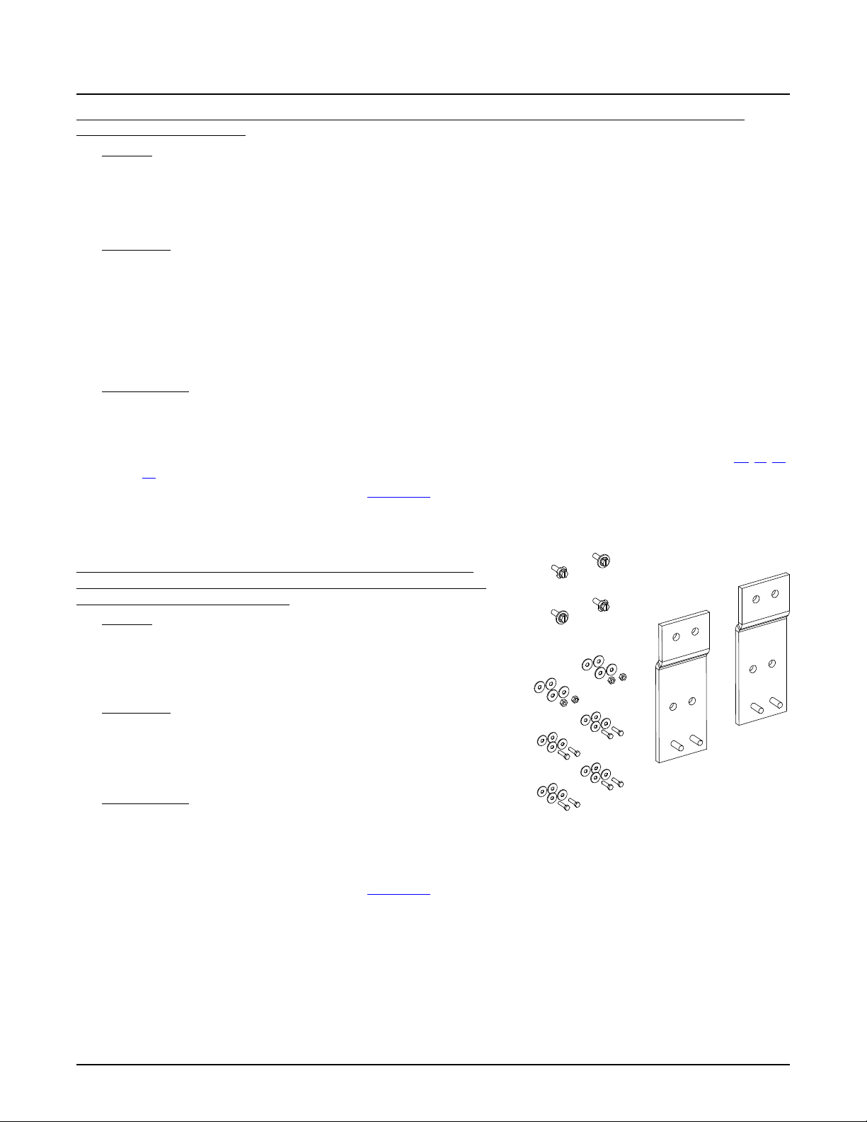
NetSure™ 7100 DC Power System
42
Shelf Mounting Hardware
Busbar Mounting Hardware
Interconnecting Busbars
System Application Guide
List 38: Module Mounting Assembly Interface Components (for Spec. No. 58870550001, 58870550002, 58870550003,
58870550004, 58870550005)
List 39: Module Mounting Assembly Field Expansion Kit (for Spec. No.
58870550002, 58870550003, 58870550004, 58870550005), For System
Mounted in a Relay Rack or Enclosure
Features
♦ Provides components to add one (1) to five (5) (relay rack mounted option) or one (1) to six (6) (enclosure mounted
option) module mounting assembly(s) (Spec. No. 58870550001, 58870550002, 58870550003, 58870550004,
58870550005) to a Main or Supplemental Bay.
♦ Refer to “Module Mounting Assembly” starting on page 99 for module mounting assembly information.
Restrictions
Includes 'module mounting assembly-to-power system/distribution cabinet' interconnect components only. The module
mounting assembly(s) must be ordered separately (choices are 58870550001, 58870550002, 58870550003, 58870550004,
58870550005).
Relay Rack Mounted Option: Each bay (when used with a List 40, 41, 42 or 43) can be equipped with a maximum of five (5)
module mounting assemblies (see List 39 for expansion assemblies).
Enclosure Mounted Option: Each bay (when used with a List 40, 41, 42 or 43) can be equipped with a maximum of six (6)
module mounting assemblies (see List 39 for expansion assemblies).
Ordering Notes
1) Order one (1) List 38 per module mounting assembly(s) Spec. No. 588705500 to be installed in the bay with these
interconnect components and specify the number of rows in the distribution cabinet so correct busbars can be provided.
2) Order module mounting assembly(s) as required. See “Module Mounting Assembly” starting on page 99 (choices are
58870550001, 58870550002, 58870550003, 58870550004, 58870550005). (58870550001 required when List 40, 41, 42
or 43 ordered with the system.)
5) Order rectifier modules as required per P/N 1R484000e.
6) Order a module mounting position blank cover panel, P/N 21140440, for each empty module mounting position in the
system, as desired.
Features
♦ Provides busbars and mounting hardware to tie the DC output busbars
in a field installed module mounting assembly Spec. No. 58870550002,
58870550003, 58870550004, 58870550005 to the system’s DC
busbars or between two (2) module expansion assemblies.
Restrictions
Maximum of two (2) List 39 per bay (total number of shelves in a bay
cannot exceed six, maximum of ten shelves (60 rectifiers) per multi-bay
system).
AC inputs MUST be wired directly to the expansion assembly(s).
Ordering Notes
1) Order List 39 for a module mounting assembly Spec. No. 588705500 to
be added in the field.
2) Order a module mounting assembly as required. See “Module Mounting Assembly” starting on page 99 (choices are
58870550002, 58870550003, 58870550004, 58870550005).
3) Order rectifier modules as required per P/N 1R484000e.
4) Order a module mounting position blank cover panel, P/N 21140440, for each empty module mounting position in the
system, as desired.
Spec. No: 582127000 SAG582127000
Model No: 7100 Revision BJ, August 21, 2020
Page 43

NetSure™ 7100 DC Power System
43
System Application Guide
List 40: Front Access AC Input Termination Assembly (1 AC Feed per 1 Rectifier, Single Phase)
Features
♦ Provides AC input terminal blocks for connection of single phase 208 VAC, 240 VAC, 277 VAC input feeds for all rectifier
positions in the bay. One (1) AC input feed required per one (1) rectifier position. Refer to “AC Input Connections to AC
Input Termination Assembly List 40 Illustration when Used with 588705000 (Nominal 208 VAC, 240 VAC, 277 VAC) or
588705300 (Nominal 208 VAC, 240 VAC) or 588705400 (Nominal 208 VAC, 240 VAC, 277 VAC) or 588705500 (Nominal
208 VAC, 240 VAC, 277 VAC) Module Mounting Assemblies with Rectifiers (1 Feed per 1 Rectifier, Single Phase)” on page
147 for specific wiring details.
Restrictions
For use with 58870500021 or 58870530001 or 58870540001 or 58870550001 module mounting assemblies only.
To be used with a maximum of five module mounting assemblies for relay rack, maximum of six module mounting assemblies
for enclosure.
588705300 only rated for 208 VAC, 240 VAC.
Factory installed only.
For initial installation only. Initial module mounting assemblies are factory wired to List 40. If a field expansion module
mounting assembly is added to the system, AC inputs MUST be wired directly to the assembly.
Cannot be used with the DC conduit box (List 28).
Ordering Notes
1) Order either List 40, 41, 42, or 43 for each bay (or order module mounting assemblies with AC input line cords, AC input
cable assemblies, or AC input terminal blocks). See “Module Mounting Assembly” starting on page 99.
List 41: Front Access AC Input Termination Assembly (1 AC Feed per 2 Rectifiers, Single Phase)
Features
♦ Provides AC input terminal blocks for connection of single phase 208 VAC, 240 VAC, 277 VAC input feeds for all rectifier
positions in the bay. One (1) AC input feed required per two (2) rectifier positions. Refer to “AC Input Connections to AC
Input Termination Assembly List 41 Illustration when used with 588705000 (Nominal 208 VAC, 240 VAC, 277 VAC) or
588705300 (Nominal 208 VAC, 240 VAC) or 588705400 (Nominal 208 VAC, 240 VAC, 277 VAC) or 588705500 (Nominal
208 VAC, 240 VAC, 277 VAC) Module Mounting Assemblies with Rectifiers (1 Feed per 2 Rectifiers, Single Phase) - with
Five (5) Shelves Installed” on page 148 for specific wiring details.
Restrictions
For use with 58870500021 or 58870530001 or 58870540001 or 58870550001 module mounting assemblies only.
To be used with a maximum of five module mounting assemblies for relay rack, maximum of six module mounting assemblies
for enclosure.
588705300 only rated for 208 VAC, 240 VAC.
Factory installed only.
For initial installation only. Initial module mounting assemblies are factory wired to List 41. If a field expansion module
mounting assembly is added to the system, AC inputs MUST be wired directly to the assembly.
Cannot be used with the DC conduit box (List 28).
Ordering Notes
1) Order either List 40, 41, 42, or 43 for each bay (or order module mounting assemblies with AC input line cords, AC input
cable assemblies, or AC input terminal blocks). See “Module Mounting Assembly” starting on page 99.
Spec. No: 582127000 SAG582127000
Model No: 7100 Revision BJ, August 21, 2020
Page 44

NetSure™ 7100 DC Power System
44
System Application Guide
List 42: Front Access AC Input Termination Assembly (1 AC Feed per 3 Rectifiers, 3-Phase)
Features
♦ Provides AC input terminal blocks for connection of three phase 208 VAC, 240 VAC input feeds for all rectifier positions
in the bay. One (1) AC input feed required per three (3) rectifier positions. Refer to “AC Input Connections to AC Input
Termination Assembly List 42 Illustration when used with 588705000 or 588705300 or 588705400 or 588705500
Module Mounting Assemblies with Rectifiers (Nominal 208 VAC, 240 VAC) (1 Feed per 3 Rectifiers, Three Phase)” on
page 153 for specific wiring details.
Note: The three-phase input is internally distributed within the system to provide a single-phase line to line connection to
each rectifier position, evenly distributed across the three phases.
Restrictions
For use with 58870500021 or 58870530001 or 58870540001 or 58870550001 module mounting assemblies only.
To be used with a maximum of five module mounting assemblies for relay rack, maximum of six module mounting assemblies
for enclosure.
Factory installed only.
For initial installation only. Initial module mounting assemblies are factory wired to List 42. If a field expansion module
mounting assembly is added to the system, AC inputs MUST be wired directly to the assembly.
Cannot be used with the DC conduit box (List 28).
Ordering Notes
1) Order either List 40, 41, 42, or 43 for each bay (or order module mounting assemblies with AC input line cords, AC input
cable assemblies, or AC input terminal blocks). See “Module Mounting Assembly” starting on page 99.
List 43: Front Access AC Input Termination Assembly (1 AC Feed per 3 Rectifiers, 3-Phase)
Features
♦ Provides AC input terminal blocks for connection of three phase 277/480 VAC input feeds for all rectifier positions in the
bay. One (1) AC input feed required per three (3) rectifier positions. Refer to “AC Input Connections to AC Input
Termination Assembly List 43 Illustration when used with 588705000 or 588705400 or 588705500 Module Mounting
Assemblies with Rectifiers (Nominal 277/480 VAC) (1 Feed per 3 Rectifiers, Three Phase)” on page 154 for specific wiring
details.
Note: The three-phase input is internally distributed within the system to provide a single-phase line to neutral connection to
each rectifier position, evenly distributed across the three phases.
Restrictions
For use with 58870500021 or 58870540001 or 58870550001 module mounting assemblies only.
To be used with a maximum of five module mounting assemblies for relay rack, maximum of six module mounting assemblies
for enclosure.
Factory installed only.
For initial installation only. Initial module mounting assemblies are factory wired to List 43. If a field expansion module
mounting assembly is added to the system, AC inputs MUST be wired directly to the assembly.
Cannot be used with the DC conduit box (List 28).
Ordering Notes
1) Order either List 40, 41, 42, or 43 for each bay (or order module mounting assemblies with AC input line cords, AC input
cable assemblies, or AC input terminal blocks). See “Module Mounting Assembly” starting on page 99.
Spec. No: 582127000 SAG582127000
Model No: 7100 Revision BJ, August 21, 2020
Page 45

NetSure™ 7100 DC Power System
45
System Application Guide
List 45: Front Access DC Input Termination Assembly
(1 DC Feed per 1 Converter, 1 to 5 Module Mounting Assemblies), For System Mounted in a Relay Rack or on Shipping Rails
Only
Features
♦ Provides DC input terminal blocks for connection of 400 volts DC input feeds for all converter positions in the bay. One
(1) DC input feed required per one (1) converter position. Refer to “400V DC Input Connections to DC Input Termination
Assembly List 45, 46, 47 Illustration when used with 588705000 Module Mounting Assemblies with Converters” on page
169 for specific wiring details.
Restrictions
Not for use with systems mounted in an enclosure.
For use with 58870500040 module mounting assembly only.
Factory installed only.
For initial installation only. Initial module mounting assemblies are factory wired to List 45. If a field expansion module
mounting assembly is added to the system, DC inputs MUST be wired directly to the assembly.
Cannot be used with the DC conduit box (List 28).
Ordering Notes
1) Order either List 45, 46, or 47 for each bay (or order module mounting assemblies with DC input terminal blocks). See
“Module Mounting Assembly” starting on page 99.
List 46: Front Access DC Input Termination Assembly (1 DC Feed per 2 Converters, 2 or 4 Assemblies), For System Mounted
in a Relay Rack or on Shipping Rails Only
Features
♦ Provides DC input terminal blocks for connection of 400 volts DC input feeds for all converter positions in the bay. One
(1) DC input feed required per two (2) converter positions. Refer to “400V DC Input Connections to DC Input
Termination Assembly List 45, 46, 47 Illustration when used with 588705000 Module Mounting Assemblies with
Converters” on page 169 for specific wiring details.
Restrictions
Not for use with systems mounted in an enclosure.
For use with 58870500040 module mounting assembly only.
Factory installed only.
For initial installation only. Initial module mounting assemblies are factory wired to List 46. If a field expansion module
mounting assembly is added to the system, DC inputs MUST be wired directly to the assembly.
List 46 can only be used with either two (2) or four (4) module mounting assemblies.
Cannot be used with the DC conduit box (List 28).
Ordering Notes
1) Order either List 45, 46, or 47 for each bay (or order module mounting assemblies with DC input terminal blocks). See
“Module Mounting Assembly” starting on page 99.
Spec. No: 582127000 SAG582127000
Model No: 7100 Revision BJ, August 21, 2020
Page 46

NetSure™ 7100 DC Power System
46
System Application Guide
List 47: Front Access DC Input Termination Assembly (1 DC Feed per 3 Converters, 1 to 5 Module Mounting Assemblies), For
System Mounted in a Relay Rack or on Shipping Rails Only
Features
♦ Provides DC input terminal blocks for connection of 400 volts DC input feeds for all converter positions in the bay. One
(1) DC input feed required per three (3) converter positions. Refer to “400V DC Input Connections to DC Input
Termination Assembly List 45, 46, 47 Illustration when used with 588705000 Module Mounting Assemblies with
Converters” on page 169 for specific wiring details.
Restrictions
Not for use with systems mounted in an enclosure.
For use with 58870500040 module mounting assembly only.
Factory installed only.
For initial installation only. Initial module mounting assemblies are factory wired to List 47. If a field expansion module
mounting assembly is added to the system, DC inputs MUST be wired directly to the assembly.
Cannot be used with the DC conduit box (List 28).
Ordering Notes
1) Order either List 45, 46, or 47 for each bay (or order module mounting assemblies with DC input terminal blocks). See
“Module Mounting Assembly” starting on page 99.
List 60: Converter Interface Components (for Spec. No. 588705300), For System Mounted in a Relay Rack or on Shipping
Rails Only
Features
♦ Provides components to interface converters in Spec. No. 588705300 module mounting assemblies to the distribution
cabinet.
Restrictions
Not for use with systems mounted in an enclosure.
Must be used in systems equipped with Spec. No. 588705300 module mounting assemblies.
Must be installed in main bay
If the system does not include a dual voltage distribution panel, the converter power cabling will be provided as ship-loose
material.
Ordering Notes
1) Order List 60 as required. Quantity of List 60 must equal the quantity of module mounting assembly(s) Spec. No.
588705300 installed in the bay with a maximum of four (4) List 60. Note that if five (5) assemblies are in the bay, the
quantity of List 60 is still four (4).
2) Specify the number of module mounting assembly(s) Spec. No. 588705300 installed in the bay (one to five) so correct
busbars can be provided.
3) Order up to three (3) converter modules, P/N 1C48241500, per module mounting assembly. Each List 60 allows the three
right-most shelf positions (when viewed from the front) to accept either converter or rectifier modules.
4) Order a module mounting position blank cover panel, P/N SXA1100035/1, for each empty module mounting position in the
system, as desired.
only.
Spec. No: 582127000 SAG582127000
Model No: 7100 Revision BJ, August 21, 2020
Page 47
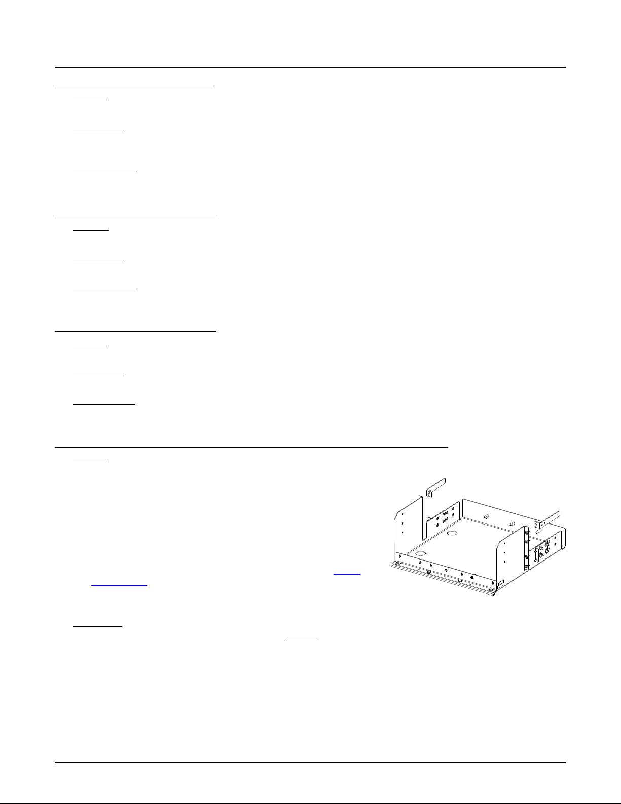
NetSure™ 7100 DC Power System
47
System Application Guide
List 90: Optional Battery Shunt, 800 A
Features
♦ Provides an 800 A battery shunt.
Restrictions
For use with List 21 only.
Cannot be used with low voltage load disconnect (LVLD) in a List 21.
Ordering Notes
1) Order as required.
List 91: Optional Battery Shunt, 2000 A
Features
♦ Provides a 2000 A battery shunt.
Restrictions
For use with List 22 only.
Ordering Notes
1) Order as required.
List 92: Optional Battery Shunt, 2500 A
Features
♦ Provides a 2500 A battery shunt.
Restrictions
For use with List 23 and 24 only. Not for use with List 5.
Ordering Notes
1) Order as required.
List 93: Optional Battery Tray, Pre-Cabled, For System Mounted in a Relay Rack Only, 22.5" Deep
Features
♦ Each List 93 provides one (1) battery tray factory mounted in the 23” wide
system relay rack specified when ordered. Each battery tray holds four
(4) 12 V front terminal valve regulated lead acid (VRLA) batteries. Battery
cabling is factory provided and connected to the system’s main busbars.
Batteries are configured as one (1) 48 VDC string per tray.
♦ Battery trays can be ordered with or without a battery disconnect circuit
breaker. When a circuit breaker is ordered, it is provided in the -48 VDC
lead of each battery string (1 circuit breaker per tray).
♦ Battery tray dimensions are 21.3” wide X 22.5” deep. Refer to “List 93
(Battery Tray)” under PHYSICAL SIZE INFORMATION for a typical battery
tray arrangement.
♦ Battery spacers included.
Restrictions
Designed to accommodate the batteries listed under “Batteries” in the ACCESSORY DESCRIPTIONS section.
A single battery tray must mount at bottom of relay rack. Multiple battery trays must mount starting at bottom of relay rack
and working upward. Factory spaces battery trays 6RU, 7RU, or 8RU apart as determined by battery selected. If no battery
selected, factory spaces battery trays 8RU apart. Spacing can be increased above that required for the battery selected up to
a maximum of 8RU.
Cable size for each tray is 2 AWG for optional battery disconnect circuit breaker selected up to 150 A and 1/0 AWG for circuit
breaker selected over 150 A or if circuit breaker is not selected.
Maximum number of List 93 per relay rack is four (4).
Spec. No: 582127000 SAG582127000
Model No: 7100 Revision BJ, August 21, 2020
Page 48
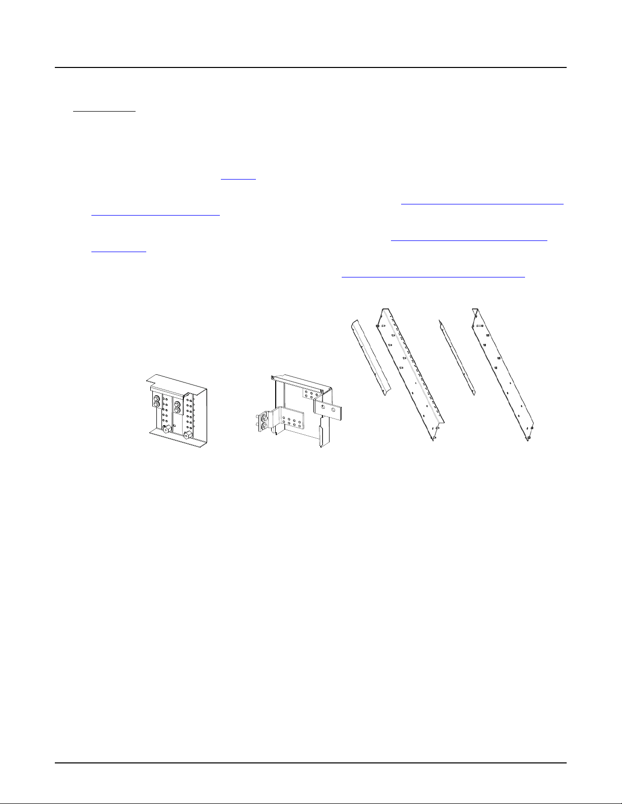
NetSure™ 7100 DC Power System
48
System Application Guide
Not a stand-alone battery system. Must be used as part of a power system that includes a List 1 (or List 5) with a List 21, 22,
23, or 24.
Ordering Notes
1) Order up to four (4) battery trays per relay rack, as required.
2) Order battery tray mounting kit P/N 565004 for use with enclosure P/N 563524 and P/N 564881.
3) Order battery cable termination kit, one per bay. P/N 553584 for use with List 21, P/N 555478 for use with Lists 22, 23
and 24.
4) Order batteries separately. See “Batteries” in the ACCESSORY DESCRIPTIONS section. Battery cables and lugs factory
provided and connected.
5) If optional battery tray battery disconnect circuit breaker is desired, order per “Optional Battery Tray Battery Disconnect
Circuit Breaker and Housing Kits” in the ACCESSORY DESCRIPTIONS section. You can order either optional battery tray
battery disconnect circuit breaker or optional battery tray Anderson battery connector kit, not both.
6) If optional battery tray Anderson battery connector kit is desired, order per “Optional Battery Tray Anderson Battery
Connector Kit” in the ACCESSORY DESCRIPTIONS section. You can order either optional battery tray battery
disconnect circuit breaker or optional battery tray Anderson battery connector kit, not both.
7) If optional battery tray front battery cover is desired, order per “Optional Battery Tray Front Battery Cover Kits” in the
ACCESSORY DESCRIPTIONS section.
P/N 553584 P/N 555478 P/N 565004
Spec. No: 582127000 SAG582127000
Model No: 7100 Revision BJ, August 21, 2020
Page 49
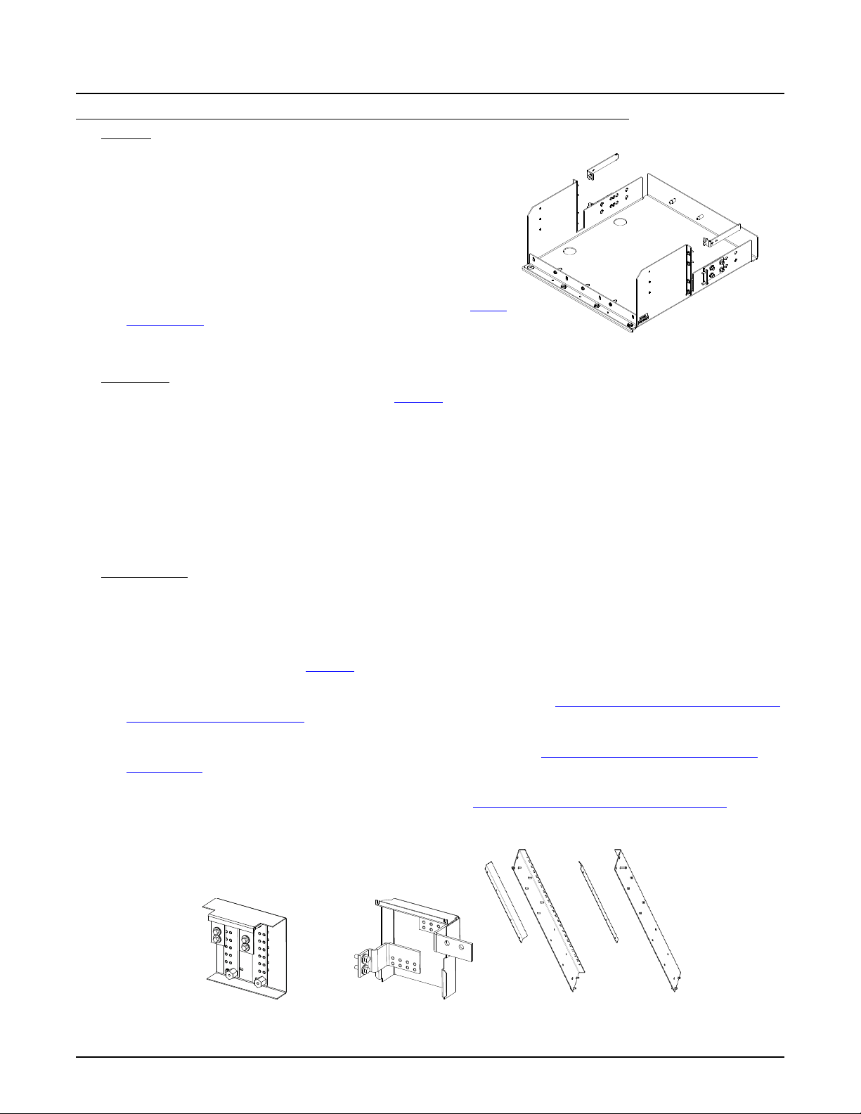
NetSure™ 7100 DC Power System
49
System Application Guide
List 95: Optional Battery Tray, Pre-Cabled, For System Mounted in a Relay Rack Only, 24.79" Deep
Features
♦ Each List 95 provides one (1) battery tray factory mounted in the 23”
wide system relay rack specified when ordered. Each battery tray
holds four (4) 12 V front terminal valve regulated lead acid (VRLA)
batteries. Battery cabling is factory provided and connected to the
system’s main busbars. Batteries are configured as one (1) 48 VDC
string per tray.
♦ Battery trays can be ordered with or without a battery disconnect
circuit breaker. When a circuit breaker is ordered, it is provided in the
-48 VDC lead of each battery string (1 circuit breaker per tray).
♦ Battery tray dimensions are 21.3” wide X 24.79” deep. Refer to “List 95
(Battery Tray)” under PHYSICAL SIZE INFORMATION for a typical
battery tray arrangement.
♦ Battery spacers included.
Restrictions
Designed to accommodate the batteries listed under “Batteries” in the ACCESSORY DESCRIPTIONS section.
A single battery tray must mount at bottom of relay rack. Multiple battery trays must mount starting at bottom of relay rack
and working upward. Factory spaces battery trays 6RU, 7RU, or 8RU apart as determined by battery selected. If no battery
selected, factory spaces battery trays 8RU apart. Spacing can be increased above that required for the battery selected up to
a maximum of 8RU.
Cable size for each tray is 2 AWG for optional battery disconnect circuit breaker selected up to 150 A and 1/0 AWG for circuit
breaker selected over 150 A or if circuit breaker is not selected.
Maximum number of List 95 per relay rack is four (4).
Not a stand-alone battery system. Must be used as part of a power system that includes a List 1 (or List 5) with a List 21, 22,
23, or 24.
Ordering Notes
1) Order up to four (4) battery trays per relay rack, as required.
2) Order battery tray mounting kit P/N 565004 for use with enclosure P/N 563524 and P/N 564881.
3) Order battery cable termination kit, one per bay. P/N 553584 for use with List 21, P/N 555478 for use with Lists 22, 23
and 24.
4) Order batteries separately. See “Batteries” in the ACCESSORY DESCRIPTIONS section. Battery cables and lugs factory
provided and connected.
5) If optional battery tray battery disconnect circuit breaker is desired, order per “Optional Battery Tray Battery Disconnect
Circuit Breaker and Housing Kits” in the ACCESSORY DESCRIPTIONS section. You can order either optional battery tray
battery disconnect circuit breaker or optional battery tray Anderson battery connector kit, not both.
6) If optional battery tray Anderson battery connector kit is desired, order per “Optional Battery Tray Anderson Battery
Connector Kit” in the ACCESSORY DESCRIPTIONS section. You can order either optional battery tray battery
disconnect circuit breaker or optional battery tray Anderson battery connector kit, not both.
7) If optional battery tray front battery cover is desired, order per “Optional Battery Tray Front Battery Cover Kits” in the
ACCESSORY DESCRIPTIONS section.
Spec. No: 582127000 SAG582127000
Model No: 7100 Revision BJ, August 21, 2020
553584 555478 565004
Page 50
NetSure™ 7100 DC Power System
50
PYL12V160FT
PYL12V185FT
System Application Guide
Batteries
Restrictions
For use in List 93 and List 95 battery trays.
Ordering Notes
1) Order batteries from Table 1a, as required for List 93.
Dimension
Manufacturer* Manufacturer P/N
C&D TEL12-160F 140456 157 5.0 x 22.0 x 11.10 7 116.8 528236 528237
C&D TEL12-180F -- 181 5.0 x 22.0 x 12.60 8 132.3 528236 528237
C&D TEL12-210F 554579 202 5.0 x 22.0 x 12.60 8 132.3 528236 528237
Deka 12AVR-150ET 122018 150 4.90 x 22.00 x 11.75 8 115 528234 528235
Deka 12AVR-170ET 541381 170 4.90 x 22.0 x 12.60 8 120 528234 528235
Deka HT170ET -- 164 4.93 x 22.17 x 12.58 8 118 528234 528235
Enersys 12V155FS 122010 155 4.90 x 22.10 x 11.10 7 106.9 528234 528235
Enersys 12V170FS -- 170 4.90 x 22.10 x 11.10 7 112 528234 528235
Enersys SBS 170F -- 170 4.92 x 22.10 x 11.10 7 116 528234 528235
Enersys SBS 190F -- 190 4.90 x 22.10 x 12.40 8 132 528234 528235
FIAMM 12FAT100 -- 100 4.96 x 21.97 x 9.06 6 95 528234 528235
FIAMM 12FAT155 -- 155 4.96 x 21.97 x 12.64 8 129 528234 528235
FIAMM 12FAT180 -- 100 4.96 x 21.97 x 12.64 8 134 528234 528235
Northstar NSB155FT RED -- 155 4.90 x 22.0 x 11.00 7 101 528234 528235
Northstar NSB170FT RED 126111 170 4.90 x 22.00 x 12.60 8 116 528234 528235
Northstar NSB190FT RED -- 190 4.90 x 22.00 x 12.60 8 123 528234 528235
Northstar NSB155FT HT -- 154 4.90 x 22.00 x 11.0 7 117 528234 528235
Northstar NSB170FT HT -- 174 4.90 x 22.00 x 12.60 8 121 528234 528235
Northstar NSB190FT HT -- 190 4.90 x 22.00 x 12.60 8 132 528234 528235
GS Yuasa
GS Yuasa
* See Battery Manufacturer Information
P/N
(12 V Module)
-- 160 4.90 x 21.90 x 11.0 7 116.2 528234 528235
-- 185 4.90 x 21.90 x 12.50 7 133.8 528234 528235
Capacity
(A-Hr)
W x L x H
(Inches)
(per 12 V Module)
Min Tray
Spacing
(RU)
Weight
(lb)
(per 12V
Module)
Lug Kit
2 AWG
Lug Kit
1/0 AWG
Table 1a
Batteries and Battery Lug Kits for List 93
2) Order batteries from Table 1b, as required for List 95.
Manufacturer* Manufacturer P/N
* See Battery Manufacturer Information
Spec. No: 582127000 SAG582127000
Model No: 7100 Revision BJ, August 21, 2020
Dimension
P/N
(12 V Module)
Deka 12AVR-200ET -- 200 4.97 x 24.3 x 12.74 8 151 528234 528235
Deka HT200ET -- 200 4.97 x 24.15 x 12.74 8 151 528234 528235
Capacity
(A-Hr)
W x L x H
(Inches)
(per 12 V Module)
Min Tray
Spacing
(RU)
Weight
(lb)
(per 12V
Module)
Lug Kit
2 AWG
Lug Kit
1/0 AWG
Table 1b
Batteries and Battery Lug Kits for List 95
Page 51
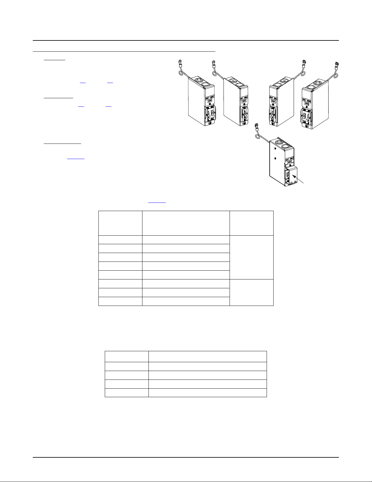
NetSure™ 7100 DC Power System
51
Provides an alarm during an electrical or manual trip condition.
Optional Circuit
Breaker Guard
System Application Guide
Optional Battery Tray Battery Disconnect Circuit Breaker and Housing Kits
Features
♦ Provides a battery disconnect circuit breaker
housing factory mounted on the left or right side
of the List 93 and List 95 battery trays. Selected
circuit breaker factory installed and wired.
Restrictions
For use in List 93 and List 95 battery trays.
Factory wires battery trays with 2 AWG cables for
battery disconnect circuit breaker selected up to 150 A
and 1/0 AWG cables for circuit breaker selected over
150 A.
Ordering Notes
1) For each battery tray, order one (1) circuit breaker
from Table 2.
2) For each double-pole circuit breaker ordered,
order an optional circuit breaker guard P/N
548014, if desired, to block front access to circuit
breaker handle.
3) For each battery tray ordered, order one (1)
battery circuit breaker housing kit from Table 3.
Ampere
Rating
Electrical/Mechanical Trip
P/N
(Black Handle)
1
No. of Poles
50 256694300
60 256694700
70 256695100
1-Pole
75 256695500
100 256695900
125 100762
150 100763
2-Pole
200 121810
Circuit Breaker Alarm Operation:
1
Table 2
Battery Tray Battery Disconnect Circuit Breakers
Part Number Description
559813 Single Pole, Right Side Mounted
559814 Single Pole, Left Side Mounted
559815 Double Pole, Right Side Mounted
559816 Double Pole, Left Side Mounted
Table 3
Battery Tray Battery Disconnect Circuit Breaker Housing Kits
Spec. No: 582127000 SAG582127000
Model No: 7100 Revision BJ, August 21, 2020
Page 52
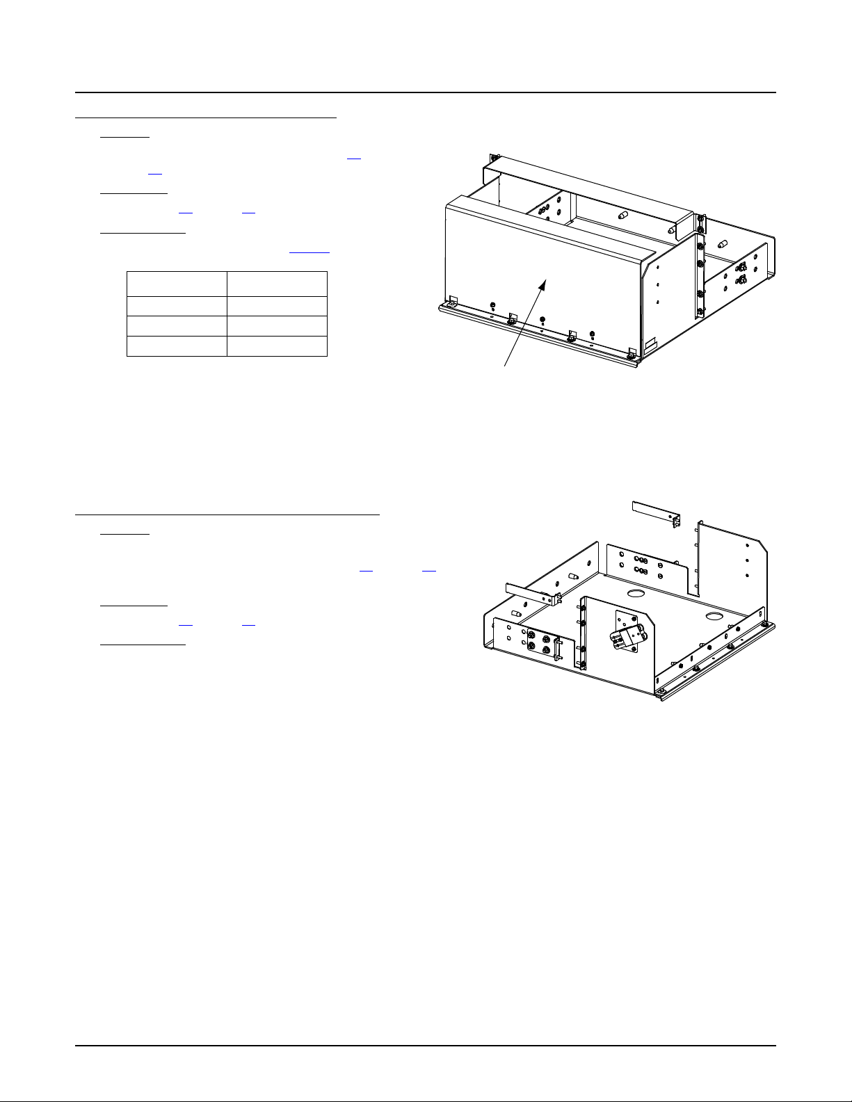
NetSure™ 7100 DC Power System
52
Optional Battery Cover
System Application Guide
Optional Battery Tray Front Battery Cover Kits
Features
♦ Provides a front battery cover to the List 93 and
List 95 battery trays.
Restrictions
For use in List 93 and List 95 battery trays.
Ordering Notes
1) Order one (1) kit per tray from Table 4, as required.
Part Number Height
562128 8U
562053 7U
562145 6U
Table 4
Optional Battery Tray Anderson Battery Connector Kit
Features
♦ Provides an Anderson battery connector (SB 120) factory
mounted on the left or right side of the List 93 and List 95
battery trays.
Restrictions
For use in List 93 and List 95 battery trays.
Ordering Notes
1) For each battery tray, order one (1) Anderson battery tray
connector kit P/N 563297.
Spec. No: 582127000 SAG582127000
Model No: 7100 Revision BJ, August 21, 2020
Page 53

NetSure™ 7100 DC Power System
53
System Application Guide
List 100: Power and Distribution Bay (Fully Configured)
Features
♦ Provides a “power and distribution” bay rated for 1000 A @ -48 VDC and 500 A @ +24 VDC, maximum.
♦ This is a preconfigured power system which is orderable by specifying one List number. This power system is
preconfigured as follows. See also “582127000 List 100 (Relay Rack)” on page 17.
All system components mounted in a 7’ x 23” seismic Zone-4 rated relay rack.
Includes a 3-row distribution cabinet.
Includes one (1) List DJ distribution panel in the top row.
Includes two (2) List AL distribution panels in the lower two rows.
Includes the NCU controller (with custom configuration).
Includes a battery disconnect contactor providing low voltage and manual battery disconnect.
Includes a system interface board which provides manual battery disconnect, system voltage test points, two (2)
temperature inputs, two (2) battery CB/Fuse alarm inputs, and a CAN interface connector.
Includes one (1) IB2 controller interface board (provides eight (8) programmable form C- relay outputs, eight (8)
programmable binary inputs, and two (2) temperature inputs).
Accepts a second optional IB2 controller interface board. See page 92.
Accepts the optional EIB controller extended interface board (provides five (5) programmable form-C relay outputs, two
(2) temperature inputs, three (3) shunt inputs. and eight (8) battery midpoint inputs). See page 93.
Accepts a second optional EIB controller extended interface board. See Restrictions. See page 93.
Includes three (3) 556155 temperature probes.
Includes the IB4 board with a second Ethernet port. The Ethernet port located on the NCU Controller’s front panel can
be used to connect a computer directly to the NCU. The Ethernet port located on the IB4 board can be used to connect
the NCU to your Local Area Network (LAN).
Includes one (1) rectifier only shelf (six positions accept rectifiers only).
Includes three (3) rectifier/converter shelves (three positions accept rectifiers only, three positions accept rectifiers or
converters).
Includes front access AC input termination assemblies with two rectifiers per AC feed, single phase.
♦ This system includes separate installation and user manuals specific to its configuration. Refer to IM582127000100 and
UM582127000100.
Ordering Notes
1) Order fuses and/or circuit breakers as required per “Distribution Devices” starting on page 118.
2) Order input and load distribution lugs, lug adapters, and lug hardware kits as required per “Recommended Wire Sizes,
Branch Circuit Protection, Crimp Lugs, and Wiring Illustrations” starting on page 131.
3) Order rectifier modules as required, P/N 1R482000e3.
4) Order optional DC-DC converter modules as required, P/N 1C48241500.
5) Order a module mounting position blank cover panel, P/N SXA1100035/1, for each empty module mounting position in the
system, as desired.
6) Order optional second IB2 controller interface board as required. See Restrictions. See page 92.
7) Order the optional EIB controller extended interface board as required (see page 93).
8) Order optional second EIB controller interface board as required. See Restrictions. See page 93.
9) For a field installed battery tray, order P/N 563206.
10) Special application rectifier bus landing point kit P/N 563686 is available for use with List 100, 101, 102, 103, and 203. Kit
P/N 563686 includes two (2) P/N 563574 Bus Landing Point Assemblies. When installed, the kit provides rectifier bus
landing points for 500 kcmil cables. Refer to “Special Application Rectifier Bus Landing Point Kit P/N 563686” on page
129.
11) A generator input circuit breaker kit P/N 564219 is available. This kit provides the components to install a 400 A circuit
breaker to feed the rectifier output bus of the power system through a shunt. A customer connects an external generator
output to this circuit breaker which then supplies generator input power to the system.
Spec. No: 582127000 SAG582127000
Model No: 7100 Revision BJ, August 21, 2020
Page 54

NetSure™ 7100 DC Power System
54
System Application Guide
List 101: Power and Distribution Bay (Fully Configured with One Battery Tray)
Features
♦ Provides a “power and distribution” bay rated for 1000 A @ -48 VDC and 500 A @ +24 VDC, maximum.
♦ This is a preconfigured power system which is orderable by specifying one List number. This power system is
preconfigured as follows. See also “582127000 List 101 (Relay Rack)” on page 18.
All system components mounted in a 5’ x 23” seismic Zone-4 rated relay rack.
Includes a 3-row distribution cabinet.
Includes one (1) List DJ distribution panel in the top row.
Includes two (2) List AL distribution panels in the lower two rows.
Includes a battery disconnect contactor providing low voltage and manual battery disconnect.
Includes the NCU controller with custom configuration.
Includes a system interface board which provides manual battery disconnect, system voltage test points, two (2)
temperature inputs, two (2) battery CB/Fuse alarm inputs, and a CAN interface connector.
Includes one (1) IB2 controller interface board (provides eight (8) programmable form C- relay outputs, eight (8)
programmable binary inputs, and two (2) temperature inputs).
Accepts a second optional IB2 controller interface board. See page 92.
Accepts the optional EIB controller extended interface board (provides five (5) programmable form-C relay outputs, two
(2) temperature inputs, three (3) shunt inputs. and eight (8) battery midpoint inputs). See page 93.
Accepts a second optional EIB controller extended interface board. See Restrictions. See page 93.
Includes three (3) 556155 temperature probes.
Includes the IB4 board with a second Ethernet port. The Ethernet port located on the NCU Controller’s front panel can
be used to connect a computer directly to the NCU. The Ethernet port located on the IB4 board can be used to connect
the NCU to your Local Area Network (LAN).
Includes one (1) rectifier only shelf (six positions accept rectifiers only).
Includes three (3) rectifier/converter shelves (three positions accept rectifiers only, three positions accept rectifiers or
converters).
Includes front access AC input termination assemblies with two rectifiers per AC feed, single phase.
Includes one (1) battery tray with 200 A disconnect circuit breakers.
♦ This system includes separate installation and user manuals specific to its configuration. Refer to IM582127000100 and
UM582127000100.
Ordering Notes
1) Order fuses and/or circuit breakers as required per “Distribution Devices” starting on page 118.
2) Order input and load distribution lugs, lug adapters, and lug hardware kits as required per “Recommended Wire Sizes,
Branch Circuit Protection, Crimp Lugs, and Wiring Illustrations” starting on page 131.
3) Order rectifier modules as required, P/N 1R482000e3.
4) Order optional DC-DC converter modules as required, P/N 1C48241500.
5) Order a module mounting position blank cover panel, P/N SXA1100035/1, for each empty module mounting position in the
system, as desired.
6) Order batteries as required per “Batteries” on page 50. Three (3) P/N 562674 battery trays provided.
7) Order optional second IB2 controller interface board as required. See Restrictions. See page 92.
8) Order the optional EIB controller extended interface board as required (see page 93).
9) Order optional second EIB controller interface board as required. See Restrictions. See page 93.
10) Special application rectifier bus landing point kit P/N 563686 is available for use with List 100, 101, 102, 103, and 203. Kit
P/N 563686 includes two (2) P/N 563574 Bus Landing Point Assemblies. When installed, the kit provides rectifier bus
landing points for 500 kcmil cables. Refer to “Special Application Rectifier Bus Landing Point Kit P/N 563686” on page
129.
11) A generator input circuit breaker kit P/N 564219 is available. This kit provides the components to install a 400 A circuit
breaker to feed the rectifier output bus of the power system through a shunt. A customer connects an external generator
output to this circuit breaker which then supplies generator input power to the system.
Spec. No: 582127000 SAG582127000
Model No: 7100 Revision BJ, August 21, 2020
Page 55

NetSure™ 7100 DC Power System
55
System Application Guide
List 102: Power and Distribution Bay (Fully Configured with Two Battery Trays)
Features
♦ Provides a “power and distribution” bay rated for 1000 A @ -48 VDC and 500 A @ +24 VDC, maximum.
♦ This is a preconfigured power system which is orderable by specifying one List number. This power system is
preconfigured as follows. See also “582127000 List 102 (Relay Rack)” on page 19.
All system components mounted in a 6’ x 23” seismic Zone-4 rated relay rack.
Includes a 3-row distribution cabinet.
Includes one (1) List DJ distribution panel in the top row.
Includes two (2) List AL distribution panels in the lower two rows.
Includes a battery disconnect contactor providing low voltage and manual battery disconnect.
Includes the NCU controller with custom configuration.
Includes a system interface board which provides manual battery disconnect, system voltage test points, two (2)
temperature inputs, two (2) battery CB/Fuse alarm inputs, and a CAN interface connector.
Includes one (1) IB2 controller interface board (provides eight (8) programmable form C- relay outputs, eight (8)
programmable binary inputs, and two (2) temperature inputs).
Accepts a second optional IB2 controller interface board. See page 92.
Accepts the optional EIB controller extended interface board (provides five (5) programmable form-C relay outputs, two
(2) temperature inputs, three (3) shunt inputs. and eight (8) battery midpoint inputs). See page 93.
Accepts a second optional EIB controller extended interface board. See Restrictions. See page 93.
Includes three (3) 556155 temperature probes.
Includes the IB4 board with a second Ethernet port. The Ethernet port located on the NCU Controller’s front panel can
be used to connect a computer directly to the NCU. The Ethernet port located on the IB4 board can be used to connect
the NCU to your Local Area Network (LAN).
Includes one (1) rectifier only shelf (six positions accept rectifiers only).
Includes three (3) rectifier/converter shelves (three positions accept rectifiers only, three positions accept rectifiers or
converters).
Includes front access AC input termination assemblies with two rectifiers per AC feed, single phase.
Includes two (2) battery trays with 200 A disconnect circuit breakers.
♦ This system includes separate installation and user manuals specific to its configuration. Refer to IM582127000100 and
UM582127000100.
Ordering Notes
1) Order fuses and/or circuit breakers as required per “Distribution Devices” starting on page 118.
2) Order input and load distribution lugs, lug adapters, and lug hardware kits as required per “Recommended Wire Sizes,
Branch Circuit Protection, Crimp Lugs, and Wiring Illustrations” starting on page 131.
3) Order rectifier modules as required, P/N 1R482000e3.
4) Order optional DC-DC converter modules as required, P/N 1C48241500.
5) Order a module mounting position blank cover panel, P/N SXA1100035/1, for each empty module mounting position in the
system, as desired.
6) Order batteries as required per “Batteries” on page 50. Three (3) P/N 562674 battery trays provided.
7) Order optional second IB2 controller interface board as required. See Restrictions. See page 92.
8) Order the optional EIB controller extended interface board as required (see page 93.).
9) Order optional second EIB controller interface board as required. See Restrictions. See page 93.
10) Special application rectifier bus landing point kit P/N 563686 is available for use with List 100, 101, 102, 103, and 203. Kit
P/N 563686 includes two (2) P/N 563574 Bus Landing Point Assemblies. When installed, the kit provides rectifier bus
landing points for 500 kcmil cables. Refer to “Special Application Rectifier Bus Landing Point Kit P/N 563686” on page
129.
11) A generator input circuit breaker kit P/N 564219 is available. This kit provides the components to install a 400 A circuit
breaker to feed the rectifier output bus of the power system through a shunt. A customer connects an external generator
output to this circuit breaker which then supplies generator input power to the system.
Spec. No: 582127000 SAG582127000
Model No: 7100 Revision BJ, August 21, 2020
Page 56

NetSure™ 7100 DC Power System
56
System Application Guide
List 103: Power and Distribution Bay (Fully Configured with Three Battery Trays)
Features
♦ Provides a “power and distribution” bay rated for 1000 A @ -48 VDC and 500 A @ +24 VDC, maximum.
♦ This is a preconfigured power system which is orderable by specifying one List number. This power system is
preconfigured as follows. See also “582127000 List 103 (Relay Rack)” on page 20.
All system components mounted in a 7’ x 23” seismic Zone-4 rated relay rack.
Includes a 3-row distribution cabinet.
Includes one (1) List DJ distribution panel in the top row.
Includes two (2) List AL distribution panels in the lower two rows.
Includes a battery disconnect contactor providing low voltage and manual battery disconnect.
Includes the NCU controller with custom configuration.
Includes a system interface board which provides manual battery disconnect, system voltage test points, two (2)
temperature inputs, two (2) battery CB/Fuse alarm inputs, and a CAN interface connector.
Includes one (1) IB2 controller interface board (provides eight (8) programmable form C- relay outputs, eight (8)
programmable binary inputs, and two (2) temperature inputs).
Accepts a second optional IB2 controller interface board. See page 92.
Accepts the optional EIB controller extended interface board (provides five (5) programmable form-C relay outputs, two
(2) temperature inputs, three (3) shunt inputs. and eight (8) battery midpoint inputs). See page 93.
Accepts a second optional EIB controller extended interface board. See Restrictions. See page 93.
Includes three (3) 556155 temperature probes.
Includes the IB4 board with a second Ethernet port. The Ethernet port located on the NCU Controller’s front panel can
be used to connect a computer directly to the NCU. The Ethernet port located on the IB4 board can be used to connect
the NCU to your Local Area Network (LAN).
Includes one (1) rectifier only shelf (six positions accept rectifiers only).
Includes three (3) rectifier/converter shelves (three positions accept rectifiers only, three positions accept rectifiers or
converters).
Includes front access AC input termination assemblies with two rectifiers per AC feed, single phase.
Includes three (3) battery trays with 150 A disconnect circuit breakers.
♦ This system includes separate installation and user manuals specific to its configuration. Refer to IM582127000100 and
UM582127000100.
Ordering Notes
1) Order fuses and/or circuit breakers as required per “Distribution Devices” starting on page 118.
2) Order input and load distribution lugs, lug adapters, and lug hardware kits as required per “Recommended Wire Sizes,
Branch Circuit Protection, Crimp Lugs, and Wiring Illustrations” starting on page 131.
3) Order rectifier modules as required, P/N 1R482000e3.
4) Order optional DC-DC converter modules as required, P/N 1C48241500.
5) Order a module mounting position blank cover panel, P/N SXA1100035/1, for each empty module mounting position in the
system, as desired.
6) Order batteries as required per “Batteries” on page 50. Three (3) P/N 562674 battery trays provided.
7) Order optional second IB2 controller interface board as required. See Restrictions. See page 92.
8) Order the optional EIB controller extended interface board as required (see page 93.).
9) Order optional second EIB controller interface board as required. See Restrictions. See page 93.
10) Special application rectifier bus landing point kit P/N 563686 is available for use with List 100, 101, 102, 103, and 203. Kit
P/N 563686 includes two (2) P/N 563574 Bus Landing Point Assemblies. When installed, the kit provides rectifier bus
landing points for 500 kcmil cables. Refer to “Special Application Rectifier Bus Landing Point Kit P/N 563686” on page
129.
11) A generator input circuit breaker kit P/N 564219 is available. This kit provides the components to install a 400 A circuit
breaker to feed the rectifier output bus of the power system through a shunt. A customer connects an external generator
output to this circuit breaker which then supplies generator input power to the system.
Spec. No: 582127000 SAG582127000
Model No: 7100 Revision BJ, August 21, 2020
Page 57

NetSure™ 7100 DC Power System
57
System Application Guide
List 203: Power and Distribution Bay (Fully Configured with Three Battery Trays)
Features
♦ Provides a “power and distribution” bay rated for 1000 A @ -48 VDC and 500 A @ +24 VDC, maximum.
♦ This is a preconfigured power system which is orderable by specifying one List number. This power system is
preconfigured as follows. See also “582127000 List 103 (Relay Rack)” on page 20.
All system components mounted in a 7’ x 23” seismic Zone-4 rated relay rack.
Includes a 3-row distribution cabinet.
Includes one (1) List DJ distribution panel in the top row.
Includes two (2) List AL distribution panels in the lower two rows.
Includes a battery disconnect contactor providing low voltage and manual battery disconnect.
Includes the NCU controller with custom configuration.
Includes a system interface board which provides manual battery disconnect, system voltage test points, two (2)
temperature inputs, two (2) battery CB/Fuse alarm inputs, and a CAN interface connector.
Includes one (1) IB2 controller interface board (provides eight (8) programmable form C- relay outputs, eight (8)
programmable binary inputs, and two (2) temperature inputs).
Accepts a second optional IB2 controller interface board. See page 92.
Accepts the optional EIB controller extended interface board (provides five (5) programmable form-C relay outputs, two
(2) temperature inputs, three (3) shunt inputs. and eight (8) battery midpoint inputs). See page 93.
Accepts a second optional EIB controller extended interface board. See Restrictions. See page 93.
Includes three (3) 556155 temperature probes.
Includes the IB4 board with a second Ethernet port. The Ethernet port located on the NCU Controller’s front panel can
be used to connect a computer directly to the NCU. The Ethernet port located on the IB4 board can be used to connect
the NCU to your Local Area Network (LAN).
Includes one (1) rectifier only shelf (six positions accept rectifiers only).
Includes three (3) rectifier/converter shelves (three positions accept rectifiers only, three positions accept rectifiers or
converters).
Includes front access AC input termination assemblies with two rectifiers per AC feed, single phase.
Includes three (3) battery trays with 200 A disconnect circuit breakers.
♦ This system includes separate installation and user manuals specific to its configuration. Refer to IM582127000100 and
UM582127000100.
Ordering Notes
1) Order fuses and/or circuit breakers as required per “Distribution Devices” starting on page 118.
2) Order input and load distribution lugs, lug adapters, and lug hardware kits as required per “Recommended Wire Sizes,
Branch Circuit Protection, Crimp Lugs, and Wiring Illustrations” starting on page 131.
3) Order rectifier modules as required, P/N 1R482000e3.
4) Order optional DC-DC converter modules as required, P/N 1C48241500.
5) Order a module mounting position blank cover panel, P/N SXA1100035/1, for each empty module mounting position in the
system, as desired.
6) Order batteries as required per “Batteries” on page 50. Three (3) P/N 562674 battery trays provided.
7) Order optional second IB2 controller interface board as required. See Restrictions. See page 92.
8) Order the optional EIB controller extended interface board as required (see page 93.).
9) Order optional second EIB controller interface board as required. See Restrictions. See page 93.
10) Special application rectifier bus landing point kit P/N 563686 is available for use with List 100, 101, 102, 103, and 203. Kit
P/N 563686 includes two (2) P/N 563574 Bus Landing Point Assemblies. When installed, the kit provides rectifier bus
landing points for 500 kcmil cables. Refer to “Special Application Rectifier Bus Landing Point Kit P/N 563686” on page
129.
11) A generator input circuit breaker kit P/N 564219 is available. This kit provides the components to install a 400 A circuit
breaker to feed the rectifier output bus of the power system through a shunt. A customer connects an external generator
output to this circuit breaker which then supplies generator input power to the system.
Spec. No: 582127000 SAG582127000
Model No: 7100 Revision BJ, August 21, 2020
Page 58
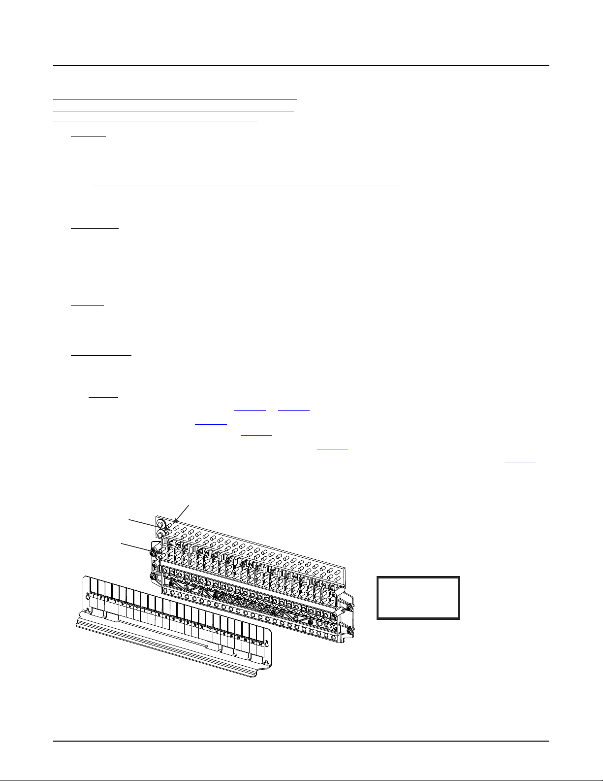
NetSure™ 7100 DC Power System
58
-48VDC Load
Connections
Load Return
Connections
LOAD AND LOAD RETURN CONNECTIONS
1/4-20 Studs on 5/8” Centers
(Customer must supply or order additional hardware)
Maximum Lug Width: 0.625 inches.
Return Busbar
(not included with List AB)
Observe proper
polarity when making
load connections.
WARNING!
Caution: 100 A circuit breakers and fuses can be used without a space
provided the continuous operating current in each 100 A device does not
exceed 64 A. A 175 A or greater circuit breaker shall have an empty
mounting position between it and any other overcurrent protective device.
System Application Guide
Single Voltage Distribution Panels
List AA: -48 VDC Distribution Panel (with Return Busbar) and
List AB: -48 VDC Distribution Panel (without Return Busbar),
(24) Bullet/TPS/TLS Circuit Breaker/Fuse Positions
Features
♦ (24) -48 VDC Load Distribution Fuse / Circuit Breaker Mounting Positions:
3 A to 100 A TPS/TLS Type Fuses,
1 A to 300 A Bullet Nose Type Circuit Breakers, or accepts
“Optional Bullet Nose Type 6-Position GMT Distribution Fuse Block (P/N 550224)”.
♦ List AA includes a return busbar; List AB does not include a return busbar.
♦ 600 A Maximum Capacity.
Restrictions
Can be installed in any row 1-4 of a 1-, 2-, 3-, or 4-row distribution cabinet.
Unless otherwise specified fuses and/or circuit breakers are mounted from left to right, starting with the highest capacity and
working to the lowest capacity.
125 A, 150 A, 175 A, and 200 A circuit breakers occupy two mounting positions.
225 A, 250 A, and 300 A circuit breakers occupy three mounting positions.
Caution: 100 A circuit breakers and fuses can be used without a space provided the continuous operating current in
each 100 A device does not exceed 64 A. A 175 A or greater circuit breaker shall have an empty mounting
position between it and any other overcurrent protective device.
Maximum lug width, 0.625 inches.
Ordering Notes
1) Specify row for panel location(s).
2) Order low voltage load disconnect List LL per panel as required.
3) List AB: To terminate load returns within the distribution cabinet, order List GA as required.
4) Order circuit breakers as required per Table 14 or Table 15.
5) Order fuses as required per Table 16. Also order one (1) P/N 117201 bullet nose type fuseholder per fuse ordered. Order
replacement alarm fuses (18/100 A) per Table 21.
6) Order 6-position GMT fuse block P/N 550224 and fuses per Table 17 as required.
7) Order load lugs (two hole, 1/4” bolt clearance hole, 5/8” centers) as required for each distribution position per Table 51.
8) Order lug hardware kit (P/N 541084) as required. Lug hardware kit provides thirty-two (32) sets of 1/4-20 hardware
(nuts, flat washers, and lock washers), enough for sixteen (16) lug landing points.
Spec. No: 582127000 SAG582127000
Model No: 7100 Revision BJ, August 21, 2020
Page 59
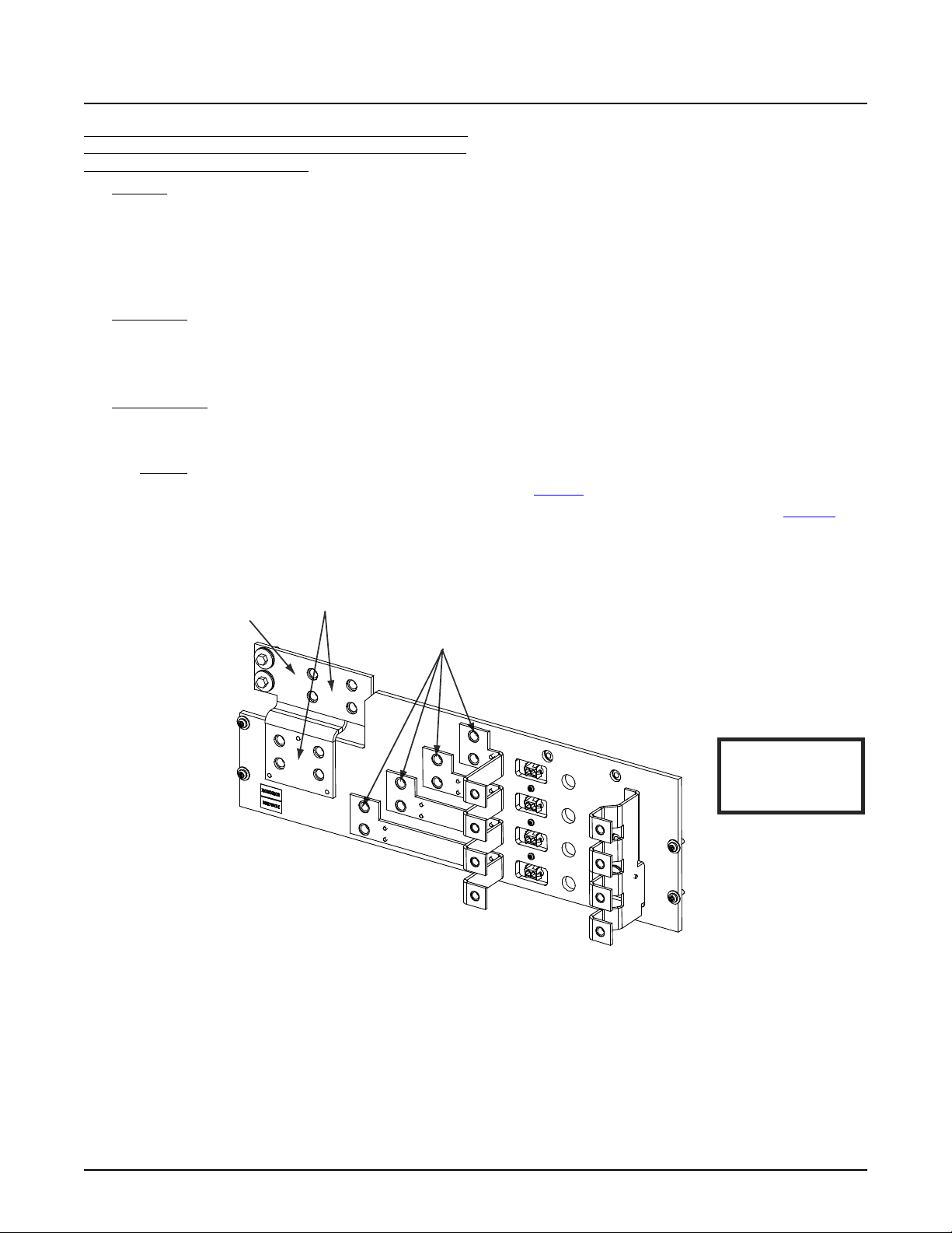
NetSure™ 7100 DC Power System
59
-48VDC Load
Connections
Load Return
Connections
LOAD AND LOAD RETURN CONNECTIONS
3/8-16 Captive Nuts on 1” Centers
(Customer must supply or order additional hardware)
Maximum Lug Width: 1.375 in ches.
Return Busbar
(not included with List AD)
Observe proper
polarity when making
load connections.
WARNING!
For an 800A circuit breaker,
continuous load must not exceed 600A.
System Application Guide
List AC: -48 VDC Distribution Panel (with Return Busbar) and
List AD: -48 VDC Distribution Panel (without Return Busbar),
(4) GJ/218 Circuit Breaker Positions
Features
♦ (4) -48 VDC Load Distribution Circuit Breaker Mounting Positions:
100 A to 800 A GJ/218 Type Circuit Breakers.
♦ List AC includes a return busbar; List AD does not include a return busbar.
♦ 600 A Maximum Capacity.
Maximum current rating of each landing point is 360 A.
Restrictions
Can be installed in any bus row 1-4 of a 1-, 2-, 3-, or 4-row distribution cabinet.
Maximum lug width, 1.375 inches.
For an 800 A circuit breaker, continuous load must not exceed 600 A.
Ordering Notes
1) Specify row for panel location(s).
2) Order low voltage load disconnect List LL per panel as required.
3) List AD: To terminate load returns within the distribution cabinet, order List GA as required.
4) Order circuit breakers and associated jumper kits as required per Table 18.
5) Order load lugs (two hole, 3/8” bolt clearance hole, 1” centers) as required for each distribution position per Table 52.
6) Order lug hardware kit (P/N 548184) as required. Lug hardware kit provides sixteen (16) sets of 3/8-16 hardware (bolts,
flat washers, and lock washers), enough for eight (8) lug landing points.
Spec. No: 582127000 SAG582127000
Model No: 7100 Revision BJ, August 21, 2020
Page 60
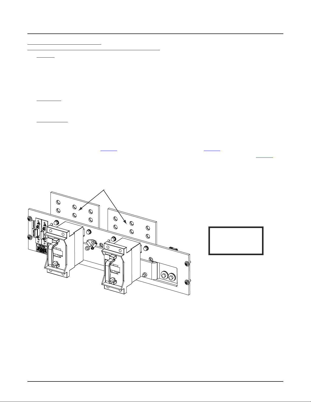
NetSure™ 7100 DC Power System
60
-48VDC Load
Connections
LOAD CONNECTIONS
3/8-16 Captive Nuts on 1” Centers
(Customer must supply or order additional hardware)
Maximum Lug Width: 1.88 inches.
Observe proper
polarity when making
load connecti ons.
WARNING!
System Application Guide
List AE: -48 VDC Distribution Panel,
(2) TPH Fuse Positions (without Shunts) (without Return Busbar)
Features
♦ (2) -48 VDC Distribution Fuse Mounting Positions:
70 A to 600 A TPH Type Fuses.
♦ Does NOT include shunts.
♦ Does NOT include a return busbar.
♦ 600 A Maximum Capacity.
Restrictions
Cannot be installed in row 1 (bottom row) of a system with a List 2, 3, 5, or 6 (supplemental bay).
Maximum lug width, 1.88 inches.
Ordering Notes
1) Specify row for panel location(s).
2) Order low voltage load disconnect List LL per panel as required.
3) To terminate load returns within the distribution cabinet, order List GA as required.
4) Order fuses as required per Table 19. Order replacement alarm fuses (1/4 A) per Table 21.
5) Order load lugs (two hole, 3/8” bolt clearance hole, 1” centers) as required for each distribution position per Table 52.
6) Order lug hardware kit (P/N 548184) as required. Lug hardware kit provides sixteen (16) sets of 3/8-16 hardware (bolts,
flat washers, and lock washers), enough for eight (8) lug landing points.
Spec. No: 582127000 SAG582127000
Model No: 7100 Revision BJ, August 21, 2020
Page 61
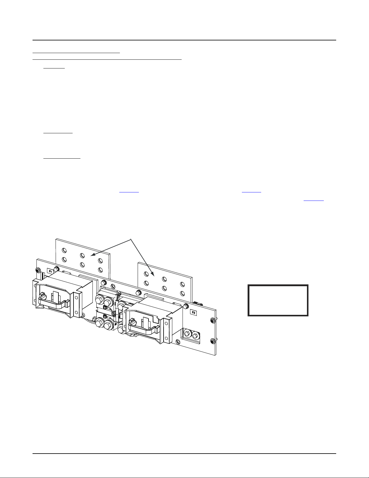
NetSure™ 7100 DC Power System
61
-48VDC Load
Connections
LOAD CONNECTIONS
3/8-16 Captive Nuts on 1” Centers
(Customer must supply or order additi onal hardware)
Maximum Lug Width: 1.88 inches.
Observe proper
polarity when making
load connections.
WARNING!
System Application Guide
List AF: -48 VDC Distribution Panel,
(2) TPH Fuse Positions (with Shunts) (without Return Busbar)
Features
♦ (2) -48 VDC Distribution Fuse Mounting Positions:
70 A to 600 A TPH Type Fuses.
♦ Includes shunts, 800 A / 25 mV. Each shunt is equipped with 10’ jumpers for connection to monitoring device. If the
system is equipped with an SM-DU+, the leads are trimmed and connected to the SM-DU+ (internal to the distribution
cabinet).
♦ Does NOT include a return busbar.
♦ 600 A Maximum Capacity.
Restrictions
Can be installed in any row 1-4 of a 1-, 2-, 3-, or 4-row distribution cabinet.
Maximum lug width, 1.88 inches.
Ordering Notes
1) Specify row for panel location(s).
2) Order low voltage load disconnect List LL per panel as required.
3) To terminate load returns within the distribution cabinet, order List GA as required.
4) Order fuses as required per Table 19. Order replacement alarm fuses (1/4 A) per Table 21.
5) Order load lugs (two hole, 3/8” bolt clearance hole, 1” centers) as required for each distribution position per Table 52.
6) Order lug hardware kit (P/N 548184) as required. Lug hardware kit provides sixteen (16) sets of 3/8-16 hardware (bolts,
flat washers, and lock washers), enough for eight (8) lug landing points.
Spec. No: 582127000 SAG582127000
Model No: 7100 Revision BJ, August 21, 2020
Page 62
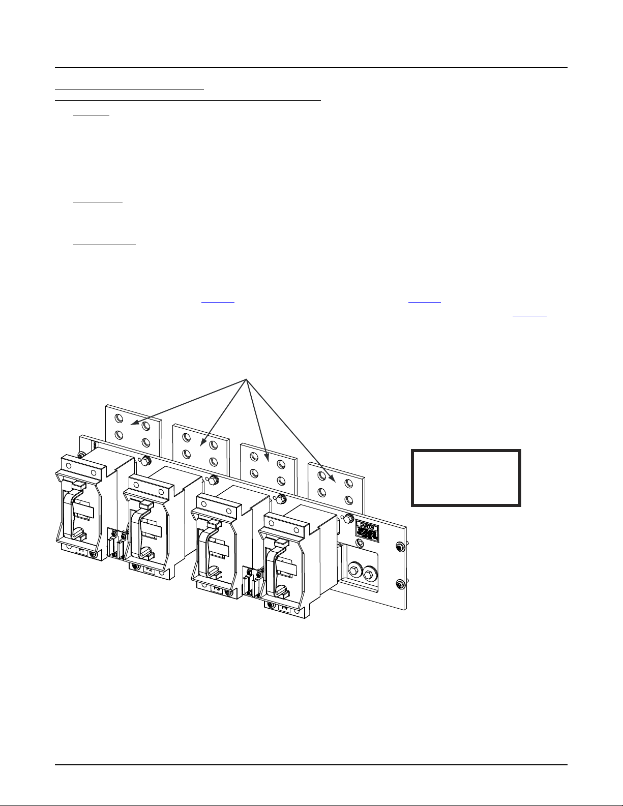
NetSure™ 7100 DC Power System
62
-48VDC Load
System Application Guide
List AG: -48 VDC Distribution Panel,
(4) TPH Fuse Positions (without Shunts) (without Return Busbar)
Features
♦ (4) -48 VDC Distribution Fuse Mounting Positions:
70 A to 400 A TPH Type Fuses.
♦ Does NOT include shunts.
♦ Does NOT include a return busbar.
♦ 600 A Maximum Capacity.
Restrictions
Cannot be installed in row 1 (bottom row) of a system with a List 2, 3, 5, or 6 (supplemental bay).
Maximum lug width, 1.75 inches.
Ordering Notes
1) Specify row for panel location(s).
2) Order low voltage load disconnect List LL per panel as required.
3) To terminate load returns within the distribution cabinet, order List GA as required.
4) Order fuses as required per Table 19. Order replacement alarm fuses (1/4 A) per Table 21.
5) Order load lugs (two hole, 3/8” bolt clearance hole, 1” centers) as required for each distribution position per Table 52.
6) Order lug hardware kit (P/N 548184) as required. Lug hardware kit provides sixteen (16) sets of 3/8-16 hardware (bolts,
flat washers, and lock washers), enough for eight (8) lug landing points.
Connections
LOAD CONNECTIONS
3/8-16 Captive Nuts on 1” Centers
(Customer must supply or order additional hardware)
Maximum Lug Width: 1.75 inches.
Maximum fuse size is 400A.
WARNING!
Observe proper
polarity when making
load connecti ons.
Spec. No: 582127000 SAG582127000
Model No: 7100 Revision BJ, August 21, 2020
Page 63
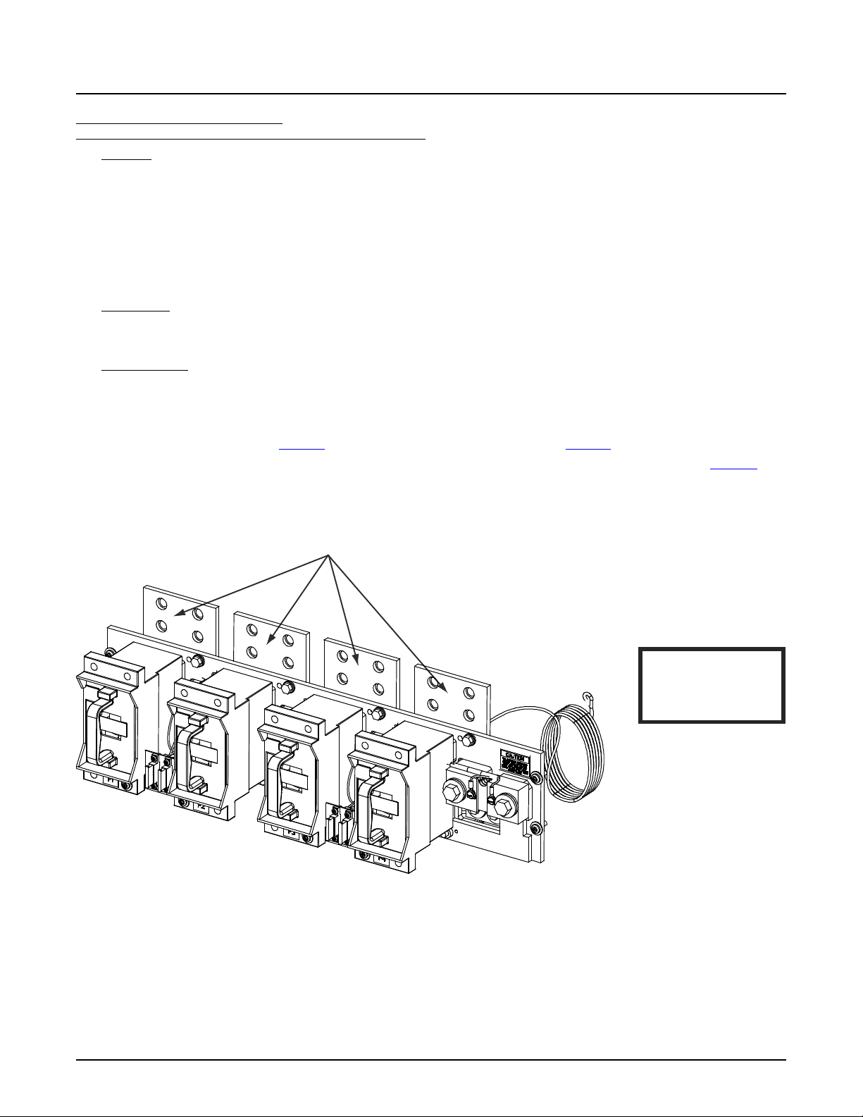
NetSure™ 7100 DC Power System
63
-48VDC Load
Connections
LOAD CONNECTIONS
3/8-16 Captive Nuts on 1” Centers
(Customer must supply or order additional h ardware)
Maximum Lug Width: 1.75 inches.
Maximum fuse size is 400A.
Observe proper
polarity when making
load connections.
WARNING!
System Application Guide
List AH: -48 VDC Distribution Panel,
(4) TPH Fuse Positions (with Shunts) (without Return Busbar)
Features
♦ (4) -48 VDC Distribution Fuse Mounting Positions:
70 A to 400 A TPH Type Fuses.
♦ Includes shunts, 600 A / 25 mV. Each shunt is equipped with 10’ jumpers for connection to monitoring device. If the
system is equipped with an SM-DU+, the leads are trimmed and connected to the SM-DU+ (internal to the distribution
cabinet).
♦ Does NOT include a return busbar.
♦ 600 A Maximum Capacity.
Restrictions
Cannot be installed in row 1 (bottom row) of a system with a List 2, 3, 5, or 6 (supplemental bay).
Maximum lug width, 1.75 inches.
Ordering Notes
1) Specify row for panel location(s).
2) Order low voltage load disconnect List LL per panel as required.
3) To terminate load returns within the distribution cabinet, order List GA as required.
4) Order fuses as required per Table 19. Order replacement alarm fuses (1/4 A) per Table 21.
5) Order load lugs (two hole, 3/8” bolt clearance hole, 1” centers) as required for each distribution position per Table 52.
6) Order lug hardware kit (P/N 548184) as required. Lug hardware kit provides sixteen (16) sets of 3/8-16 hardware (bolts,
flat washers, and lock washers), enough for eight (8) lug landing points.
Spec. No: 582127000 SAG582127000
Model No: 7100 Revision BJ, August 21, 2020
Page 64
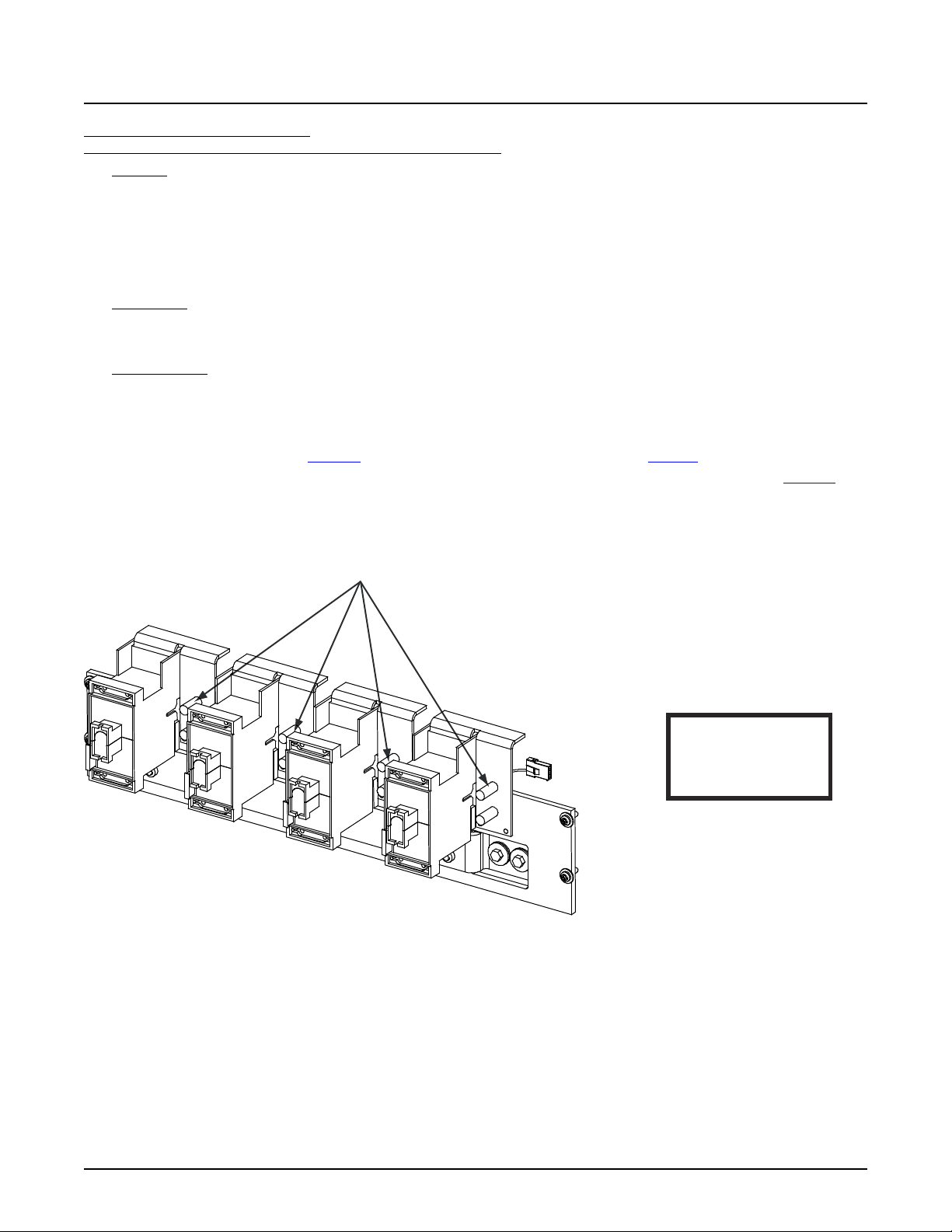
NetSure™ 7100 DC Power System
64
-48VDC Load
Connections
LOAD CONNECTIONS
3/8-16 Studs on 1” Cen ters
(Customer must supply or order additional hardware)
Maximum Lug Width: 1.5 inches.
Observe proper
polarity when making
load connections.
WARNING!
System Application Guide
List AJ: -48 VDC Distribution Panel,
(4) TPL-B Fuse Positions (without Shunts) (without Return Busbar)
Features
♦ (4) -48 VDC Distribution Fuse Mounting Positions:
70 A to 250 A TPL-B Type Fuses.
♦ Does NOT include shunts.
♦ Does NOT include a return busbar.
♦ 600 A Maximum Capacity.
Restrictions
Can be installed in any row 1-4 of a 1-, 2-, 3-, or 4-row distribution cabinet.
Maximum lug width, 1.50 inches.
Ordering Notes
1) Specify row for panel location(s).
2) Order low voltage load disconnect List LL per panel as required.
3) To terminate load returns within the distribution cabinet, order List GA as required.
4) Order fuses as required per Table 20. Order replacement alarm fuses (18/100 A) per Table 21.
5) Order load lugs (two hole, 3/8” bolt clearance hole, 1” centers) as required for each distribution position per Table 52.
6) Order lug hardware kit (P/N 548185) as required. Lug hardware kit provides sixteen (16) sets of 3/8-16 hardware (nuts,
flat washers, and lock washers), enough for eight (8) lug landing points.
Spec. No: 582127000 SAG582127000
Model No: 7100 Revision BJ, August 21, 2020
Page 65
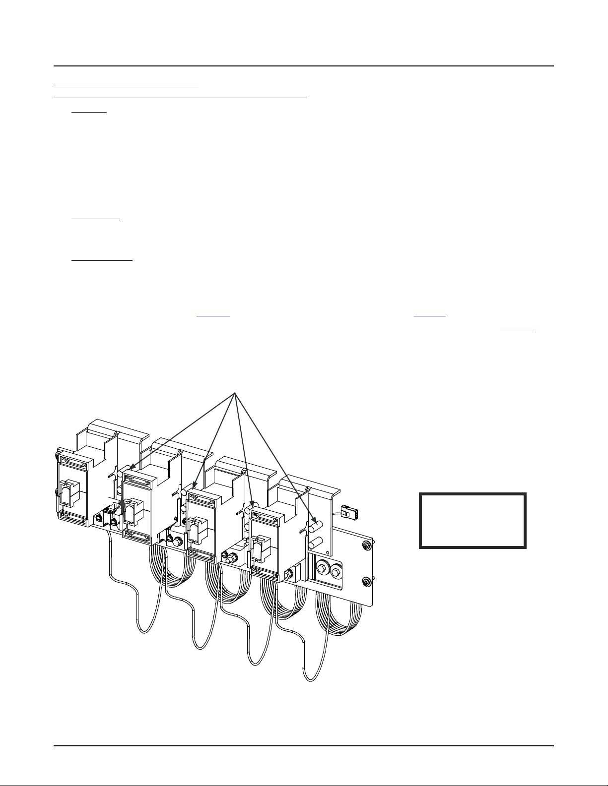
NetSure™ 7100 DC Power System
65
-48VDC Load
System Application Guide
List AK: -48 VDC Distribution Panel,
(4) TPL-B Fuse Positions (with Shunts) (without Return Busbar)
Features
♦ (4) -48 VDC Distribution Fuse Mounting Positions:
70 A to 250 A TPL-B Type Fuses.
♦ Includes shunts, 300 A / 25 mV. Each shunt is equipped with 10’ jumpers for connection to monitoring device. If the
system is equipped with an SM-DU+, the leads are trimmed and connected to the SM-DU+ (internal to the distribution
cabinet).
♦ Does NOT include a return busbar.
♦ 600 A Maximum Capacity.
Restrictions
Can be installed in any row 1-4 of a 1-, 2-, 3-, or 4-row distribution cabinet.
Maximum lug width, 1.50 inches.
Ordering Notes
1) Specify row for panel location(s).
2) Order low voltage load disconnect List LL per panel as required.
3) To terminate load returns within the distribution cabinet, order List GA as required.
4) Order fuses as required per Table 20. Order replacement alarm fuses (18/100 A) per Table 21.
5) Order load lugs (two hole, 3/8” bolt clearance hole, 1” centers) as required for each distribution position per Table 52.
6) Order lug hardware kit (P/N 548185) as required. Lug hardware kit provides sixteen (16) sets of 3/8-16 hardware (nuts,
flat washers, and lock washers), enough for eight (8) lug landing points.
Connections
LOAD CONNECTIONS
3/8-16 Studs on 1” Cen ters
(Customer must supply or order additional hardware)
Maximum Lug Width: 1.5 inches.
WARNING!
Observe proper
polarity when making
load connecti ons.
Spec. No: 582127000 SAG582127000
Model No: 7100 Revision BJ, August 21, 2020
Page 66
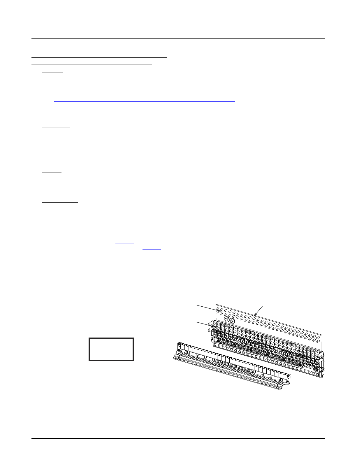
NetSure™ 7100 DC Power System
66
Observe proper
polarity when making
load connections.
WARNING!
-48 VDC Load
Connections
Load Return
Connections
LOAD AND LOAD RETURN CONNECTIONS
1/4-20 Studs on 5/8” Centers
(Customer must supply or order additional hardware)
Maximum Lug Width: 0.625 inches.
Return Busbar
(not included with List AN)
Caution: A 100 A circuit breakers and fuses can be used without a space
provided the continuous operating current in each 100 A device does not
exceed 64 A. A 175 A or greater circuit breaker shall have an empty mounting position
between it and any other overcurrent protective device.
System Application Guide
List AL: -48 VDC Distribution Panel (with Return Busbar) and
List AN: -48 V Distribution Panel (without Return Busbar)
(26) Bullet/TPS/TLS Circuit Breaker/Fuse Positions
Features
♦ (26) -48 VDC Load Distribution Fuse / Circuit Breaker Mounting Positions:
3 A to 100 A TPS/TLS Type Fuses,
1 A to 300 A Bullet Nose Type Circuit Breakers, or accepts
“Optional Bullet Nose Type 6-Position GMT Distribution Fuse Block (P/N 549017)”.
♦ List AL includes a return busbar; List AN does not include a return busbar.
♦ 600 A Maximum Capacity.
Restrictions
Can be installed in any row 1-4 of a 1-, 2-, 3-, or 4-row distribution cabinet.
Unless otherwise specified fuses and/or circuit breakers are mounted from left to right, starting with the highest capacity and
working to the lowest capacity.
125 A, 150 A, 175 A, and 200 A circuit breakers occupy two mounting positions.
225 A, 250 A, and 300 A circuit breakers occupy three mounting positions.
Caution: 100 A circuit breakers and fuses can be used without a space provided the continuous operating current in
each 100 A device does not exceed 64 A. A 175 A or greater circuit breaker shall have an empty mounting
position between it and any other overcurrent protective device.
Maximum lug width, 0.625 inches.
Ordering Notes
1) Specify row for panel location(s).
2) Order low voltage load disconnect List LL per panel as required.
3) List AN: To terminate load returns within the distribution cabinet, order List GA as required.
4) Order circuit breakers as required per Table 14 or Table 15.
5) Order fuses as required per Table 16. Also order one (1) P/N 117201 bullet nose type fuseholder per fuse ordered. Order
replacement alarm fuses (18/100 A) per Table 21.
6) Order 6-position GMT fuse block P/N 549017 and fuses per Table 17 as required.
7) Order load lugs (two hole, 1/4” bolt clearance hole, 5/8” centers) as required for each distribution position per Table 51.
8) Order lug hardware kit (P/N 541084) as required. Lug hardware kit provides thirty-two (32) sets of 1/4-20 hardware
(nuts, flat washers, and lock washers), enough for sixteen (16) lug landing points.
9) When replacing a List AA, AB, AC, AD, AE, AF, AG, AH, AJ, AK, DA, DB, DC, DD, BA, BB, BC, BD, BE, BF, BG, or BH with a
List AL; order busbar per Table 5. Existing busbar required to be replaced with this busbar.
Spec. No: 582127000 SAG582127000
Model No: 7100 Revision BJ, August 21, 2020
Page 67
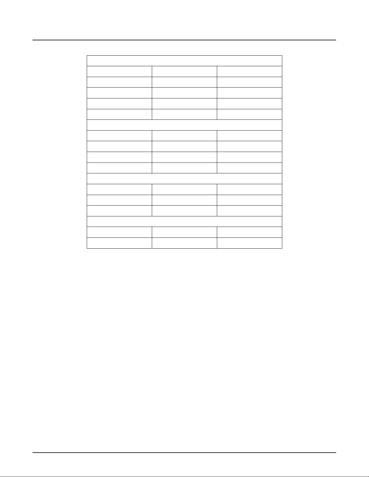
NetSure™ 7100 DC Power System
67
System Application Guide
Row Existing Busbar P/N New Busbar P/N
4-Row Distribution Cabinet
4
3
2
1
548274 562432
548273 562435
548272 562433
548271 562434
3-Row Distribution Cabinet
Row Existing Busbar P/N New Busbar P/N
3
2
1
548274 562432
548272 562433
548271 562434
2-Row Distribution Cabinet
Row Existing Busbar P/N New Busbar P/N
2
1
548273 562507
548271 562434
1-Row Distribution Cabinet
Row Existing Busbar P/N New Busbar P/N
1
548271 562434
Table 5
Spec. No: 582127000 SAG582127000
Model No: 7100 Revision BJ, August 21, 2020
Page 68
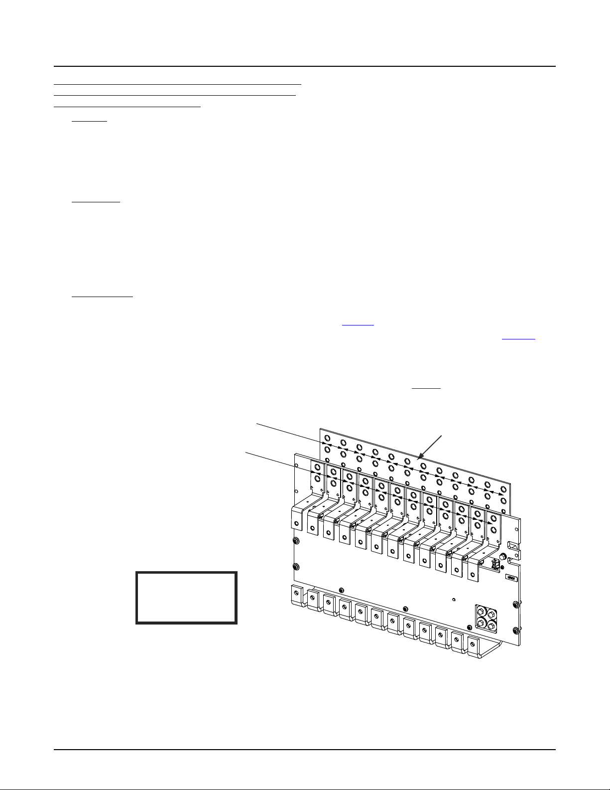
NetSure™ 7100 DC Power System
68
Observe proper
polarity when making
load connections.
WARNING!
Load Return
Connections
LOAD AND LOAD RETURN CONNECTIONS
3/8-16 Captive Nuts on 1” Centers
(Customer must supply or order additi onal hardware)
Maximum Lug Width: 1.375 inches.
Return Busbar
(not included with Li st AP)
-48 VDC Load
Connections
System Application Guide
List AM: -48 VDC Distribution Panel (with Return Busbar) and
List AP: -48 VDC Distribution Panel (without Return Busbar)
(12) GJ/218 Circuit Breaker Positions
Features
♦ (12) -48 VDC Load Distribution Circuit Breaker Mounting Positions:
100 A to 800 A GJ/218 Type Circuit Breakers.
♦ Includes a return busbar
♦ 1600 A Maximum Capacity.
Maximum current rating of each landing point is 360 A.
Restrictions
Unless otherwise specified circuit breakers are mounted from left to right, starting with the highest capacity and working to
the lowest capacity.
Can be installed in any two adjacent bus rows 1-2, 2-3, or 3-4 of a 2-, 3-, or 4-row distribution cabinet.
List LL is not available in any row if the system is equipped with one or more List EA, List AM, or List AP.
Maximum lug width, 1.375 inches.
For an 800 A circuit breaker, continuous load must not exceed 600 A.
Ordering Notes
1) Specify rows for panel location(s) (each List AM and AP requires two rows).
2) Order circuit breakers and associated jumper kits as required per Table 18.
3) Order load lugs (two hole, 3/8” bolt clearance hole, 1” centers) as required for each distribution position per Table 52.
4) Order lug hardware kit (P/N 548184) as required. Lug hardware kit provides sixteen (16) sets of 3/8-16 hardware (bolts,
flat washers, and lock washers), enough for eight (8) lug landing points.
5) When replacing a List AA, AB, AC, AD, AE, AF, AG, AH, AJ, AK, DA, DB, DC, DD, BA, BB, BC, BD, BE, BF, BG, or BH with a
List AM or List AP (return side busbar not required with List AP); order busbars per Table 6. Existing busbars required to
be replaced with these busbars.
Spec. No: 582127000 SAG582127000
Model No: 7100 Revision BJ, August 21, 2020
Page 69

NetSure™ 7100 DC Power System
69
System Application Guide
When replacing a List AA, AB, AC, AD, AE, AF, AG, AH, AJ, AK, DA, DB, DC, DD, BA, BB, BC, BD, BE, BF, BG, or BH with List AM
or List AP (return side busbar not required with List AP), remove two (2) hot side and two (2) return side busbars from
corresponding positions (2-rows) and replace with new busbars ordered from Table 6.
4-Row Distribution Cabinet without LVLD
Existing Busbar New Busbar
Row Return Side Hot Side Row Return Side Hot Side
4 548274 561774 3-4 562444 562441
3 548273 561773 2-3 562445 562442
2 548272 561772 1-2 562446 562443
1 548271 562822 -- -- --
3-Row Distribution Cabinet without LVLD
Existing Busbar New Busbar
Row Return Side Hot Side Row Return Side Hot Side
3 548274 561774 2-3 562448 562447
2 548272 561881 1-2 562451 562443
1 548271 562822 -- -- --
2-Row Distribution Cabinet without LVLD
Existing Busbar New Busbar
Row Return Side Hot Side Row Return Side Hot Side
2 548273 561773 1-2 562449 562443
1 548271 562822 -- -- --
Table 6
Spec. No: 582127000 SAG582127000
Model No: 7100 Revision BJ, August 21, 2020
Page 70
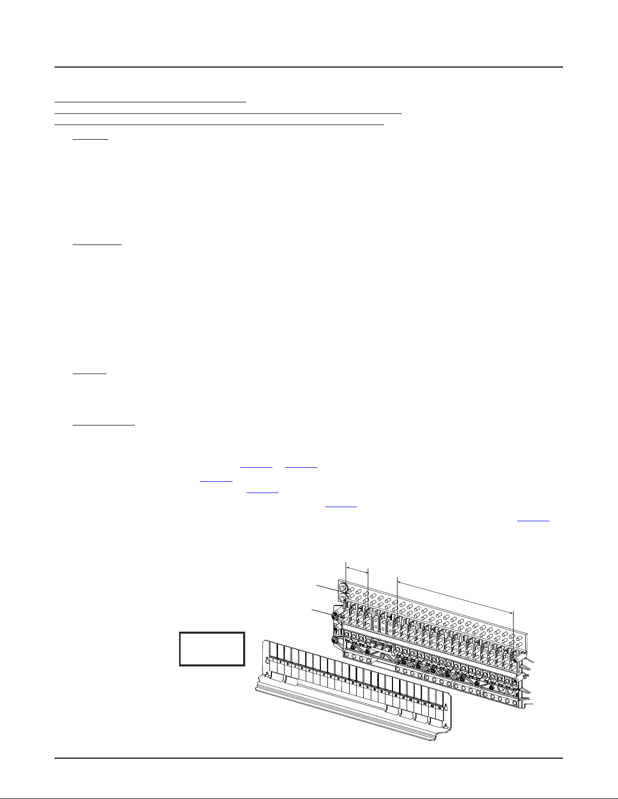
NetSure™ 7100 DC Power System
70
Load
Connections
Load Return
Connections
LOAD AND LOAD RETURN CONNECTIONS
1/4-20 Studs on 5/8” Centers
(Customer must supply
or order additional
hardware)
Maximum Lug Width:
0.625 inches.
-
4
8V
D
i
s
tr
i
bu
ti
on
+
2
4V
D
i
s
tr
i
b
ut
i
o
n
Observe proper
polarity when making
load connections.
WARNING!
Caution: A 100 A circuit breakers and fuses can be used without a space
provided the continuous operatingcurrent in each 100 A device does notexceed
64 A. A 175 A or greater circuit breaker shallhave an empty mounting position
between it and any other overcurrent protective device.
System Application Guide
Dual Voltage Distribution Panels
List DA: -48 VDC / +24 VDC Distribution Panel,
(17) -48 VDC Bullet/TPS/TLS Circuit Breaker/Fuse Positions (with Return Busbar) and
(4) +24 VDC Bullet/TPS/TLS Circuit Breaker/Fuse Positions (with Return Busbar)
Features
♦ (17) -48 VDC Load Distribution Fuse / Circuit Breaker Mounting Positions:
(4) +24 VDC Load Distribution Fuse / Circuit Breaker Mounting Positions:
3 A to 100 A TPS/TLS Type Fuses, 1 A to 300 A Bullet Nose Type Circuit Breakers.
♦ Includes a return busbar.
♦ 600 A Maximum Total Capacity:
600 A Maximum -48 VDC Distribution Capacity.
256 A Maximum +24 VDC Distribution Capacity.
Restrictions
Cannot be used in a supplemental bay.
Limit two (2) dual voltage distribution panels per power system. If two dual voltage distribution panels are ordered, they must
be mounted in adjacent rows and must be the same List Number. Maximum subsystem current capacity of the second panel
is 255 A based on the cables that are provided to connect it to the first panel.
Can be installed in rows 1 to 2 of a 1-, 2-, 3-, or 4-row distribution cabinet.
Unless otherwise specified fuses and/or circuit breakers are mounted from left to right, starting with the highest capacity and
working to the lowest capacity.
125 A, 150 A, 175 A, and 200 A circuit breakers occupy two mounting positions.
225 A, 250 A, and 300 A circuit breakers occupy three mounting positions.
Caution: 100 A circuit breakers and fuses can be used without a space provided the continuous operating current in
each 100 A device does not exceed 64 A. A 175 A or greater circuit breaker shall have an empty mounting
position between it and any other overcurrent protective device.
Maximum lug width, 0.625 inches.
Ordering Notes
1) Specify row for panel location(s).
2) Order low voltage load disconnect List LL (for 48 V positions) as required.
3) Order circuit breakers as required per Table 14 or Table 15.
4) Order fuses as required per Table 16. Also order one (1) P/N 117201 bullet nose type fuseholder per fuse ordered. Order
replacement alarm fuses (18/100 A) per Table 21.
5) Order 6-position GMT fuse block P/N 550224 and fuses per Table 17 as required.
6) Order load lugs (two hole, 1/4” bolt clearance hole, 5/8” centers) as required for each distribution position per Table 51.
7) Order lug hardware kit (P/N 541084) as required. Lug hardware kit provides thirty-two (32) sets of 1/4-20 hardware
(nuts, flat washers, and lock washers), enough for sixteen (16) lug landing points.
Spec. No: 582127000 SAG582127000
Model No: 7100 Revision BJ, August 21, 2020
Page 71
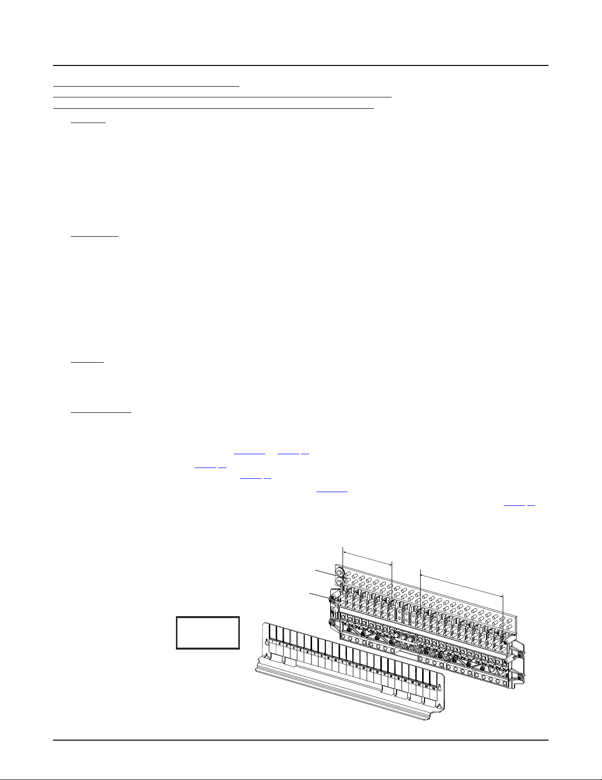
NetSure™ 7100 DC Power System
71
Load
Connections
Load Return
Connections
LOAD AND LOAD RETURN CONNECTIONS
1/4-20 Studs on 5/8” Centers
(Customer must supply
or order additional
hardware)
Maximum Lug Width:
0.625 inches.
-
4
8V
D
i
s
tr
i
b
uti
on
+
2
4V
D
i
s
tr
i
bu
ti
on
Observe proper
polarity when making
load connections.
WARNING!
Caution: 100 A circuit breakersand fuses can be used without a space provided
the continuous operating current in each 100 A device does not exceed 64 A.
A 175 A orgreater circuit breakershall have an empty mounting position between it
and any other overcurrentprotective device.
System Application Guide
List DB: -48 VDC / +24 VDC Distribution Panel,
(13) -48 VDC Bullet/TPS/TLS Circuit Breaker/Fuse Positions (with Return Busbar) and
(8) +24 VDC Bullet/TPS/TLS Circuit Breaker/Fuse Positions (with Return Busbar)
Features
♦ (13) -48 VDC Load Distribution Fuse / Circuit Breaker Mounting Positions:
(8) +24 VDC Load Distribution Fuse / Circuit Breaker Mounting Positions:
3 A to 100 A TPS/TLS Type Fuses,
1 A to 300 A Bullet Nose Type Circuit Breakers.
♦ Includes a return busbar.
♦ 600 A Maximum Total Capacity:
600 A Maximum -48 VDC Distribution Capacity.
500 A Maximum +24 VDC Distribution Capacity.
Restrictions
Cannot be used in a supplemental bay.
Limit two (2) dual voltage distribution panels per power system. If two dual voltage distribution panels are ordered, they must
be mounted in adjacent rows and must be the same List Number. Maximum subsystem current capacity of the second panel
is 255 A based on the cables that are provided to connect it to the first panel.
Can be installed in rows 1 to 2 of a 1-, 2-, 3-, or 4-row distribution cabinet.
Unless otherwise specified fuses and/or circuit breakers are mounted from left to right, starting with the highest capacity and
working to the lowest capacity.
125 A, 150 A, 175 A, and 200 A circuit breakers occupy two mounting positions.
225 A, 250 A, and 300 A circuit breakers occupy three mounting positions.
Caution: 1100 A circuit breakers and fuses can be used without a space provided the continuous operating current in
each 100 A device does not exceed 64 A. A 175 A or greater circuit breaker shall have an empty mounting
position between it and any other overcurrent protective device.
Maximum lug width, 0.625 inches.
Ordering Notes
1) Specify row for panel location(s).
2) Order low voltage load disconnect List LL (for 48 V positions) as required.
3) Order circuit breakers as required per Table 14 or Table 15.
4) Order fuses as required per Table 16. Also order one (1) P/N 117201 bullet nose type fuseholder per fuse ordered. Order
replacement alarm fuses (18/100 A) per Table 21.
5) Order 6-position GMT fuse block P/N 550224 and fuses per Table 17 as required.
6) Order load lugs (two hole, 1/4” bolt clearance hole, 5/8” centers) as required for each distribution position per Table 51.
7) Order lug hardware kit (P/N 541084) as required. Lug hardware kit provides thirty-two (32) sets of 1/4-20 hardware
(nuts, flat washers, and lock washers), enough for sixteen (16) lug landing points.
Spec. No: 582127000 SAG582127000
Model No: 7100 Revision BJ, August 21, 2020
Page 72
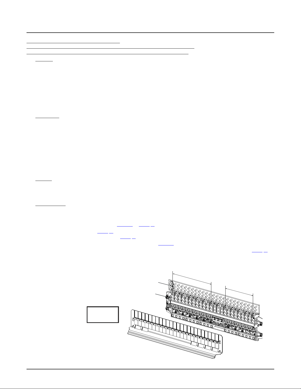
NetSure™ 7100 DC Power System
72
Load
Connections
Load Return
Connections
LOAD AND LOAD RETURN CONNECTIONS
1/4-20 Studs on 5/8” Centers
(Customer must supply
or order additional
hardware)
Maximum Lug Width:
0.625 inches.
-
4
8V
D
i
s
tr
i
b
uti
on
+
2
4
V
D
i
s
t
r
i
bu
ti
o
n
Observe proper
polarity when making
load connections.
WARNING!
Caution: 100 A circuit breakers andfuses can be used without a space provided
the continuous operating currentin each 100 A device does notexceed 64 A.
A 175 A or greater circuit breaker shall have an empty mounting position between it
and any other overcurrent protective device.
System Application Guide
List DC: -48 VDC / +24 VDC Distribution Panel,
(9) -48 VDC Bullet/TPS/TLS Circuit Breaker/Fuse Positions (with Return Busbar) and
(12) +24 VDC Bullet/TPS/TLS Circuit Breaker/Fuse Positions (with Return Busbar)
Features
♦ (9) -48 VDC Load Distribution Fuse / Circuit Breaker Mounting Positions:
(12) +24 VDC Load Distribution Fuse / Circuit Breaker Mounting Positions:
3 A to 100 A TPS/TLS Type Fuses,
1 A to 300 A Bullet Nose Type Circuit Breakers.
♦ Includes a return busbar.
♦ 600 A Maximum Total Capacity:
576 A Maximum -48 VDC Distribution Capacity.
500 A Maximum +24 VDC Distribution Capacity.
Restrictions
Cannot be used in a supplemental bay.
Limit two (2) dual voltage distribution panels per power system. If two dual voltage distribution panels are ordered, they must
be mounted in adjacent rows and must be the same List Number. Maximum subsystem current capacity of the second panel
is 255 A based on the cables that are provided to connect it to the first panel.
Can be installed in rows 1 to 2 of a 1-, 2-, 3-, or 4-row distribution cabinet.
Unless otherwise specified fuses and/or circuit breakers are mounted from left to right, starting with the highest capacity and
working to the lowest capacity.
125 A, 150 A, 175 A, and 200 A circuit breakers occupy two mounting positions.
225 A, 250 A, and 300 A circuit breakers occupy three mounting positions.
Caution: 100 A circuit breakers and fuses can be used without a space provided the continuous operating current in
each 100 A device does not exceed 64 A. A 175 A or greater circuit breaker shall have an empty mounting
position between it and any other overcurrent protective device.
Maximum lug width, 0.625 inches.
Ordering Notes
1) Specify row for panel location(s).
2) Order low voltage load disconnect List LL (for 48 V positions) as required.
3) Order circuit breakers as required per Table 14 or Table 15.
4) Order fuses as required per Table 16. Also order one (1) P/N 117201 bullet nose type fuseholder per fuse ordered. Order
replacement alarm fuses (18/100 A) per Table 21.
5) Order 6-position GMT fuse block P/N 550224 and fuses per Table 17 as required.
6) Order load lugs (two hole, 1/4” bolt clearance hole, 5/8” centers) as required for each distribution position per Table 51.
7) Order lug hardware kit (P/N 541084) as required. Lug hardware kit provides thirty-two (32) sets of 1/4-20 hardware
(nuts, flat washers, and lock washers), enough for sixteen (16) lug landing points.
Spec. No: 582127000 SAG582127000
Model No: 7100 Revision BJ, August 21, 2020
Page 73
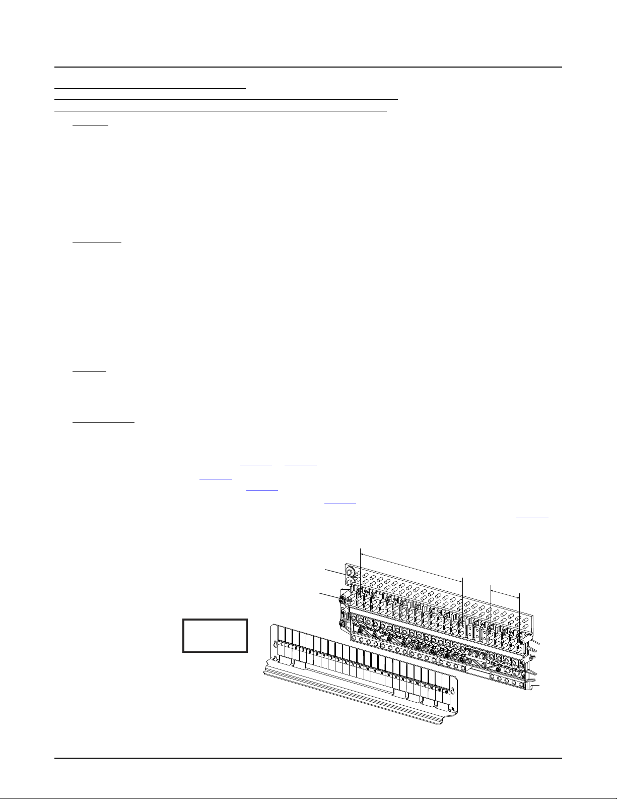
NetSure™ 7100 DC Power System
73
Load
Connections
-
4
8V
D
i
s
tr
i
b
u
ti
o
n
+
2
4V
D
i
s
t
r
i
b
uti
on
Load Return
Connections
LOAD AND LOAD RETURN CONNECTIONS
1/4-20 Studs on 5/8” Centers
(Customer must supply
or order additional
hardware)
Maximum Lug Width:
0.625 inches.
Observe proper
polarity when making
load connections.
WARNING!
Caution: 100 A circuitbreakers and fuses can be used withouta space provided
the continuous operating currentin each 100 A device does not exceed 64 A.
A 175 A or greater circuit breaker shall havean empty mounting positionbetween it
and any other overcurrentprotective device.
System Application Guide
List DD: -48 VDC / +24 VDC Distribution Panel,
(5) -48 VDC Bullet/TPS/TLS Circuit Breaker/Fuse Positions (with Return Busbar) and
(16) +24 VDC Bullet/TPS/TLS Circuit Breaker/Fuse Positions (with Return Busbar)
Features
♦ (5) -48 VDC Load Distribution Fuse / Circuit Breaker Mounting Positions:
(16) +24 VDC Load Distribution Fuse / Circuit Breaker Mounting Positions:
3 A to 100 A TPS/TLS Type Fuses,
1 A to 300 A Bullet Nose Type Circuit Breakers.
♦ Includes a return busbar.
♦ 600 A Maximum Total Capacity:
320 A Maximum -48 VDC Distribution Capacity.
500 A Maximum +24 VDC Distribution Capacity.
Restrictions
Cannot be used in a supplemental bay.
Limit two (2) dual voltage distribution panels per power system. If two dual voltage distribution panels are ordered, they must
be mounted in adjacent rows and must be the same List Number. Maximum subsystem current capacity of the second panel
is 255 A based on the cables that are provided to connect it to the first panel.
Can be installed in rows 1 to 2 of a 1-, 2-, 3-, or 4-row distribution cabinet.
Unless otherwise specified fuses and/or circuit breakers are mounted from left to right, starting with the highest capacity and
working to the lowest capacity.
125 A, 150 A, 175 A, and 200 A circuit breakers occupy two mounting positions.
225 A, 250 A, and 300 A circuit breakers occupy three mounting positions.
Caution: 100 A circuit breakers and fuses can be used without a space provided the continuous operating current in
each 100 A device does not exceed 64 A. A 175 A or greater circuit breaker shall have an empty mounting
position between it and any other overcurrent protective device.
Maximum lug width, 0.625 inches.
Ordering Notes
1) Specify row for panel location(s).
2) Order low voltage load disconnect List LL (for 48 V positions) as required.
3) Order circuit breakers as required per Table 14 or Table 15.
4) Order fuses as required per Table 16. Also order one (1) P/N 117201 bullet nose type fuseholder per fuse ordered. Order
replacement alarm fuses (18/100 A) per Table 21.
5) Order 6-position GMT fuse block P/N 550224 and fuses per Table 17 as required.
6) Order load lugs (two hole, 1/4” bolt clearance hole, 5/8” centers) as required for each distribution position per Table 51.
7) Order lug hardware kit (P/N 541084) as required. Lug hardware kit provides thirty-two (32) sets of 1/4-20 hardware
(nuts, flat washers, and lock washers), enough for sixteen (16) lug landing points.
Spec. No: 582127000 SAG582127000
Model No: 7100 Revision BJ, August 21, 2020
Page 74
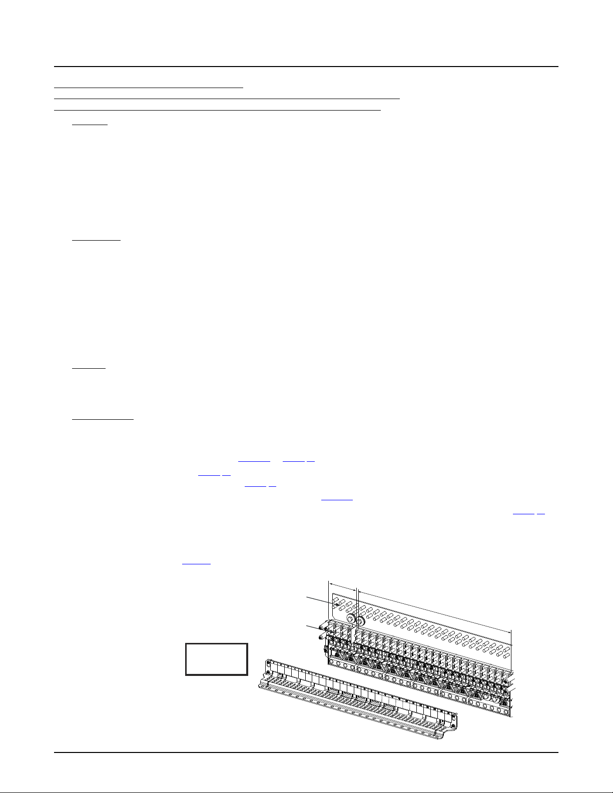
NetSure™ 7100 DC Power System
74
Observe proper
polarity when making
load connections.
WARNING!
-
4
8V
D
i
s
tr
i
bu
t
i
on
+24
V
D
i
s
tr
i
b
u
ti
o
n
LOAD AND LOAD RETURN CONNECTIONS
1/4-20 Studs on5/8” Centers
(Customer must supply
or order additional
hardware)
Maximum Lug Width:
0.625 inches.
Load
Connections
Load Return
Connections
Caution: 100 A circuit breakers and fuses can be usedwithout a space
provided the continuousoperating current in each 100A device does not exceed 64 A.
A 175 A or greater circuit breaker shallhave an empty mounting position betweenit
and any other overcurrent protective device.
System Application Guide
List DE: -48 VDC / +24 VDC Distribution Panel,
(22) -48 VDC Bullet/TPS/TLS Circuit Breaker/Fuse Positions (with Return Busbar) and
(4) +24 VDC Bullet/TPS/TLS Circuit Breaker/Fuse Positions (with Return Busbar)
Features
♦ (22) -48 VDC Load Distribution Fuse / Circuit Breaker Mounting Positions:
(4) +24 VDC Load Distribution Fuse / Circuit Breaker Mounting Positions:
3 A to 100 A TPS/TLS Type Fuses,
1 A to 300 A Bullet Nose Type Circuit Breakers.
♦ Includes a return busbar.
♦ 600 A Maximum Total Capacity:
600 A Maximum -48 VDC Distribution Capacity.
500 A Maximum +24 VDC Distribution Capacity.
Restrictions
Cannot be used in a supplemental bay.
Limit two (2) dual voltage distribution panels per power system. If two dual voltage distribution panels are ordered, they must
be mounted in adjacent rows. Maximum subsystem current capacity of the second panel is 255 A based on the cables that
are provided to connect it to the first panel.
Can be installed in any row of a 1-, 2-, 3-, or 4-row distribution cabinet.
Unless otherwise specified fuses and/or circuit breakers are mounted from left to right, starting with the highest capacity and
working to the lowest capacity.
125 A, 150 A, 175 A, and 200 A circuit breakers occupy two mounting positions.
225 A, 250 A, and 300 A circuit breakers occupy three mounting positions.
Caution: 100 A circuit breakers and fuses can be used without a space provided the continuous operating current in
each 100 A device does not exceed 64 A. A 175 A or greater circuit breaker shall have an empty mounting
position between it and any other overcurrent protective device.
Maximum lug width, 0.625 inches.
Ordering Notes
1) Specify row for panel location(s).
2) Order low voltage load disconnect List LL (for 48 V positions) as required.
3) Order circuit breakers as required per Table 14 or Table 15.
4) Order fuses as required per Table 16. Also order one (1) P/N 117201 bullet nose type fuseholder per fuse ordered. Order
replacement alarm fuses (18/100 A) per Table 21.
5) Order 6-position GMT fuse block P/N 549017 and fuses per Table 17 as required.
6) Order load lugs (two hole, 1/4” bolt clearance hole, 5/8” centers) as required for each distribution position per Table 51.
7) Order lug hardware kit (P/N 541084) as required. Lug hardware kit provides thirty-two (32) sets of 1/4-20 hardware
(nuts, flat washers, and lock washers), enough for sixteen (16) lug landing points.
8) When replacing a List AA, AB, AC, AD, AE, AF, AG, AH, AJ, AK, DA, DB, DC, DD, BA, BB, BC, BD, BE, BF, BG, or BH with this
panel; order busbar per Table 5. Existing busbar required to be replaced with this busbar.
Spec. No: 582127000 SAG582127000
Model No: 7100 Revision BJ, August 21, 2020
Page 75
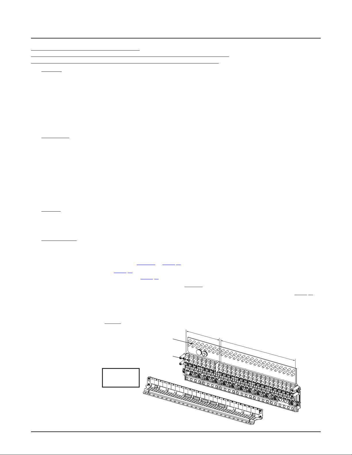
NetSure™ 7100 DC Power System
75
Observe proper
polarity when making
load connections.
WARNING!
-
48
V
D
i
s
tr
i
bu
t
i
o
n
+
2
4
V
D
i
s
tr
i
b
uti
on
LOAD AND LOAD RETURN CONNECTIONS
1/4-20 Studs on 5/8”Centers
(Customer must supply
or order additional
hardware)
Maximum Lug Width:
0.625 inches.
Load
Connections
Load Return
Connections
Caution: 100 A circuitbreakers and fuses can be used without a space provided
the continuous operatingcurrent in each 100 A device does not exceed 64 A.
A 175 A or greater circuitbreaker shall have an empty mounting position betweenit
and any other overcurrentprotective device.
System Application Guide
List DF: -48 VDC / +24 VDC Distribution Panel,
(18) -48 VDC Bullet/TPS/TLS Circuit Breaker/Fuse Positions (with Return Busbar) and
(8) +24 VDC Bullet/TPS/TLS Circuit Breaker/Fuse Positions (with Return Busbar)
Features
♦ (18) -48 VDC Load Distribution Fuse / Circuit Breaker Mounting Positions:
(8) +24 VDC Load Distribution Fuse / Circuit Breaker Mounting Positions:
3 A to 100 A TPS/TLS Type Fuses,
1 A to 300 A Bullet Nose Type Circuit Breakers.
♦ Includes a return busbar.
♦ 600 A Maximum Total Capacity:
600 A Maximum -48 VDC Distribution Capacity.
500 A Maximum +24 VDC Distribution Capacity.
Restrictions
Cannot be used in a supplemental bay.
Limit two (2) dual voltage distribution panels per power system. If two dual voltage distribution panels are ordered, they must
be mounted in adjacent rows. Maximum subsystem current capacity of the second panel is 255 A based on the cables that
are provided to connect it to the first panel.
Can be installed in any row of a 1-, 2-, 3-, or 4-row distribution cabinet.
Unless otherwise specified fuses and/or circuit breakers are mounted from left to right, starting with the highest capacity and
working to the lowest capacity.
125 A, 150 A, 175 A, and 200 A circuit breakers occupy two mounting positions.
225 A, 250 A, and 300 A circuit breakers occupy three mounting positions.
Caution: 100 A circuit breakers and fuses can be used without a space provided the continuous operating current in
each 100 A device does not exceed 64 A. A 175 A or greater circuit breaker shall have an empty mounting
position between it and any other overcurrent protective device.
Maximum lug width, 0.625 inches.
Ordering Notes
1) Specify row for panel location(s).
2) Order low voltage load disconnect List LL (for 48 V positions) as required.
3) Order circuit breakers as required per Table 14 or Table 15.
4) Order fuses as required per Table 16. Also order one (1) P/N 117201 bullet nose type fuseholder per fuse ordered. Order
replacement alarm fuses (18/100 A) per Table 21.
5) Order 6-position GMT fuse block P/N 549017 and fuses per Table 17 as required.
6) Order load lugs (two hole, 1/4” bolt clearance hole, 5/8” centers) as required for each distribution position per Table 51.
7) Order lug hardware kit (P/N 541084) as required. Lug hardware kit provides thirty-two (32) sets of 1/4-20 hardware
(nuts, flat washers, and lock washers), enough for sixteen (16) lug landing points.
8) When replacing a List AA, AB, AC, AD, AE, AF, AG, AH, AJ, AK, DA, DB, DC, DD, BA, BB, BC, BD, BE, BF, BG, or BH with this
panel; order busbar per Table 5. Existing busbar required to be replaced with this busbar.
Spec. No: 582127000 SAG582127000
Model No: 7100 Revision BJ, August 21, 2020
Page 76
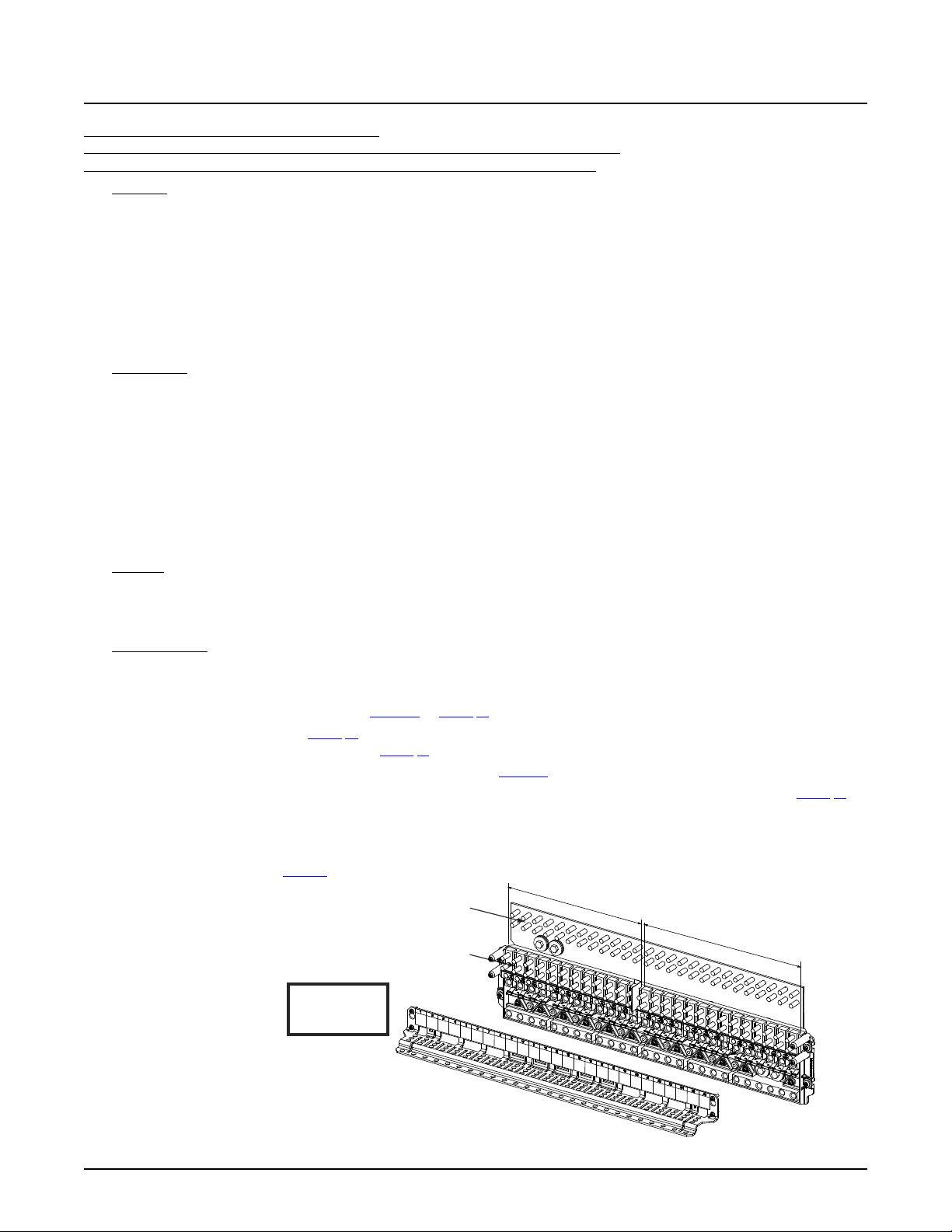
NetSure™ 7100 DC Power System
76
Observe proper
polarity when making
load connections.
WARNING!
-
48
V
D
i
s
tr
i
bu
ti
o
n
+
2
4V
D
i
s
t
r
i
b
uti
on
LOAD AND LOAD RETURN CONNECTIONS
1/4-20 Studs on 5/8”Centers
(Customer must supply
or order additional
hardware)
Maximum Lug Width:
0.625 inches.
Load
Connections
Load Return
Connections
Caution: 100 A circuit breakers andfuses can be used without a space
provided the continuous operating current ineach 100 A device does not exceed 64 A.
A 175 A or greater circuit breaker shall have an empty mountingposition between it
and any other overcurrent protective device.
System Application Guide
List DG: -48 VDC / +24 VDC Distribution Panel,
(14) -48 VDC Bullet/TPS/TLS Circuit Breaker/Fuse Positions (with Return Busbar) and
(12) +24 VDC Bullet/TPS/TLS Circuit Breaker/Fuse Positions (with Return Busbar)
Features
♦ (14) -48 VDC Load Distribution Fuse / Circuit Breaker Mounting Positions:
(12) +24 VDC Load Distribution Fuse / Circuit Breaker Mounting Positions:
3 A to 100 A TPS/TLS Type Fuses,
1 A to 300 A Bullet Nose Type Circuit Breakers.
♦ Includes a return busbar.
♦ 600 A Maximum Total Capacity:
600 A Maximum -48 VDC Distribution Capacity.
500 A Maximum +24 VDC Distribution Capacity.
Restrictions
Cannot be used in a supplemental bay.
Limit two (2) dual voltage distribution panels per power system. If two dual voltage distribution panels are ordered, they must
be mounted in adjacent rows. Maximum subsystem current capacity of the second panel is 255 A based on the cables that
are provided to connect it to the first panel.
Can be installed in any row of a 1-, 2-, 3-, or 4-row distribution cabinet.
Unless otherwise specified fuses and/or circuit breakers are mounted from left to right, starting with the highest capacity and
working to the lowest capacity.
125 A, 150 A, 175 A, and 200 A circuit breakers occupy two mounting positions.
225 A, 250 A, and 300 A circuit breakers occupy three mounting positions.
Caution: 100 A circuit breakers and fuses can be used without a space provided the continuous operating current in
each 100 A device does not exceed 64 A. A 175 A or greater circuit breaker shall have an empty mounting
position between it and any other overcurrent protective device.
Maximum lug width, 0.625 inches.
Ordering Notes
1) Specify row for panel location(s).
2) Order low voltage load disconnect List LL (for 48 V positions) as required.
3) Order circuit breakers as required per Table 14 or Table 15.
4) Order fuses as required per Table 16. Also order one (1) P/N 117201 bullet nose type fuseholder per fuse ordered. Order
replacement alarm fuses (18/100 A) per Table 21.
5) Order 6-position GMT fuse block P/N 549017 and fuses per Table 17 as required.
6) Order load lugs (two hole, 1/4” bolt clearance hole, 5/8” centers) as required for each distribution position per Table 51.
7) Order lug hardware kit (P/N 541084) as required. Lug hardware kit provides thirty-two (32) sets of 1/4-20 hardware
(nuts, flat washers, and lock washers), enough for sixteen (16) lug landing points.
8) When replacing a List AA, AB, AC, AD, AE, AF, AG, AH, AJ, AK, DA, DB, DC, DD, BA, BB, BC, BD, BE, BF, BG, or BH with this
panel; order busbar per Table 5. Existing busbar required to be replaced with this busbar.
Spec. No: 582127000 SAG582127000
Model No: 7100 Revision BJ, August 21, 2020
Page 77
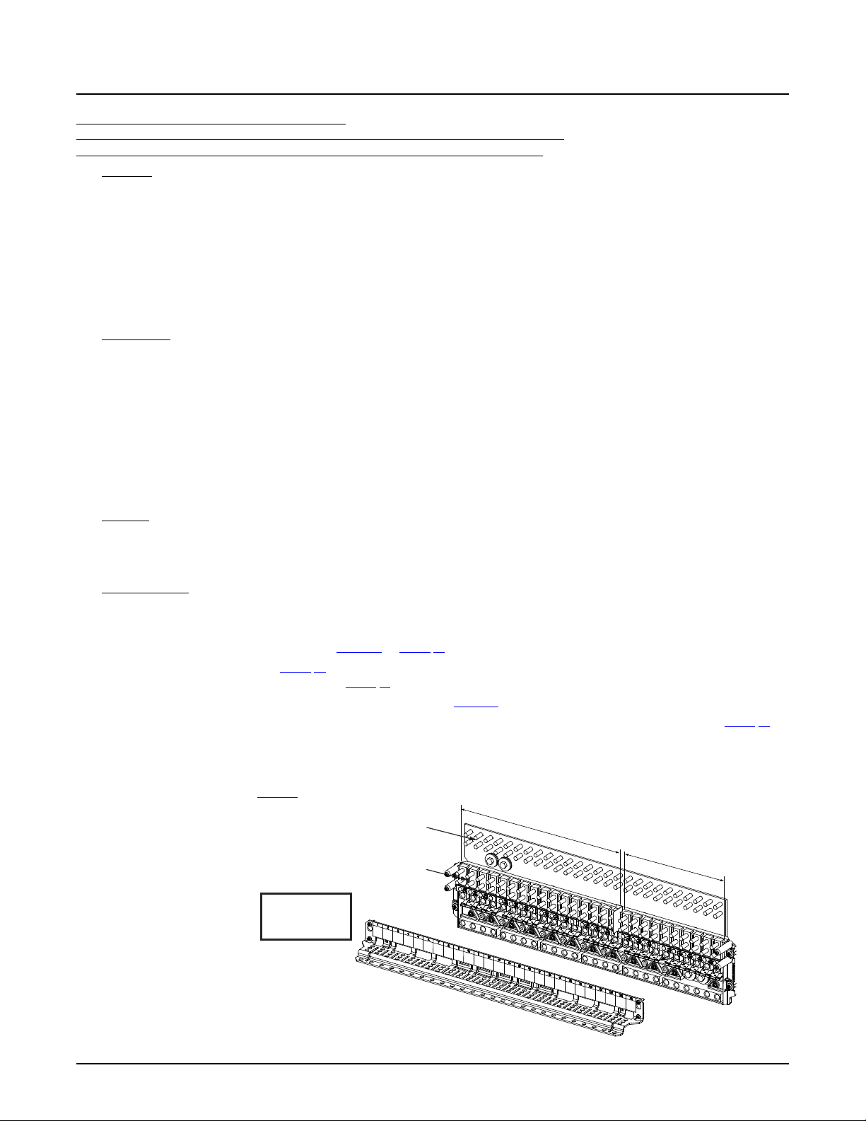
NetSure™ 7100 DC Power System
77
Observe proper
polarity when making
load connections.
WARNING!
-
48
V
D
i
s
t
r
i
b
ut
i
o
n
+
2
4V
D
i
s
tr
i
bu
ti
on
LOAD AND LOAD RETURN CONNECTIONS
1/4-20 Studs on 5/8” Centers
(Customer must supply
or order additional
hardware)
Maximum Lug Width:
0.625 inches.
Load
Connections
Load Return
Connections
Caution: 100 A circuit breakers and fuses can beused without a space provided
the continuous operating currentin each 100 A device does not exceed 64 A.
A 175 A orgreater circuit breakershall have an empty mounting position between it
and any other overcurrentprotective device.
System Application Guide
List DH: -48 VDC / +24 VDC Distribution Panel,
(10) -48 VDC Bullet/TPS/TLS Circuit Breaker/Fuse Positions (with Return Busbar) and
(16) +24 VDC Bullet/TPS/TLS Circuit Breaker/Fuse Positions (with Return Busbar)
Features
♦ (10) -48 VDC Load Distribution Fuse / Circuit Breaker Mounting Positions:
(16) +24 VDC Load Distribution Fuse / Circuit Breaker Mounting Positions:
3 A to 100 A TPS/TLS Type Fuses,
1 A to 300 A Bullet Nose Type Circuit Breakers.
♦ Includes a return busbar.
♦ 600 A Maximum Total Capacity:
600 A Maximum -48 VDC Distribution Capacity.
500 A Maximum +24 VDC Distribution Capacity.
Restrictions
Cannot be used in a supplemental bay.
Limit two (2) dual voltage distribution panels per power system. If two dual voltage distribution panels are ordered, they must
be mounted in adjacent rows. Maximum subsystem current capacity of the second panel is 255 A based on the cables that
are provided to connect it to the first panel.
Can be installed in any row of a 1-, 2-, 3-, or 4-row distribution cabinet.
Unless otherwise specified fuses and/or circuit breakers are mounted from left to right, starting with the highest capacity and
working to the lowest capacity.
125 A, 150 A, 175 A, and 200 A circuit breakers occupy two mounting positions.
225 A, 250 A, and 300 A circuit breakers occupy three mounting positions.
Caution: 100 A circuit breakers and fuses can be used without a space provided the continuous operating current in
each 100 A device does not exceed 64 A. A 175 A or greater circuit breaker shall have an empty mounting
position between it and any other overcurrent protective device.
Maximum lug width, 0.625 inches.
Ordering Notes
1) Specify row for panel location(s).
2) Order low voltage load disconnect List LL (for 48 V positions) as required.
3) Order circuit breakers as required per Table 14 or Table 15.
4) Order fuses as required per Table 16. Also order one (1) P/N 117201 bullet nose type fuseholder per fuse ordered. Order
replacement alarm fuses (18/100 A) per Table 21.
5) Order 6-position GMT fuse block P/N 549017 and fuses per Table 17 as required.
6) Order load lugs (two hole, 1/4” bolt clearance hole, 5/8” centers) as required for each distribution position per Table 51.
7) Order lug hardware kit (P/N 541084) as required. Lug hardware kit provides thirty-two (32) sets of 1/4-20 hardware
(nuts, flat washers, and lock washers), enough for sixteen (16) lug landing points.
8) When replacing a List AA, AB, AC, AD, AE, AF, AG, AH, AJ, AK, DA, DB, DC, DD, BA, BB, BC, BD, BE, BF, BG, or BH with this
panel; order busbar per Table 5. Existing busbar required to be replaced with this busbar.
Spec. No: 582127000 SAG582127000
Model No: 7100 Revision BJ, August 21, 2020
Page 78
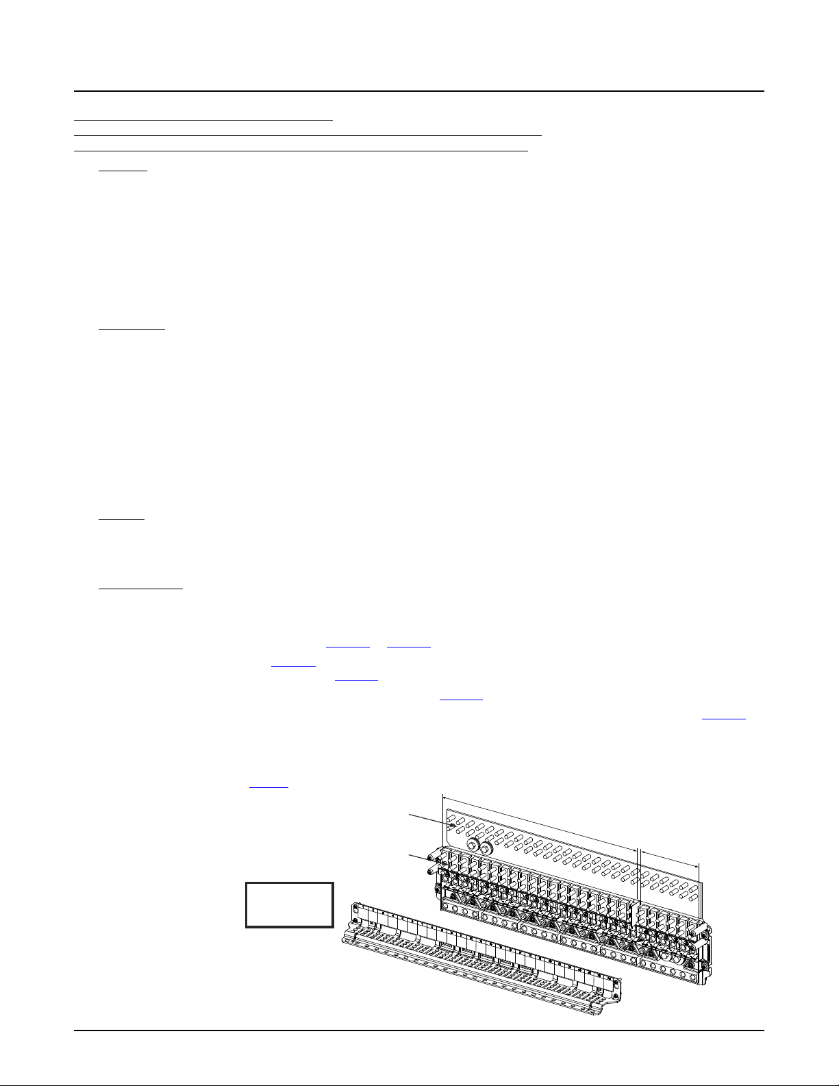
NetSure™ 7100 DC Power System
78
Observe proper
polarity when making
load connections.
WARNING!
-
4
8V
D
i
s
tr
i
b
u
ti
o
n
+
2
4V
D
i
s
tr
i
bu
ti
on
LOAD AND LOAD RETURN CONNECTIONS
1/4-20 Studs on 5/8” Centers
(Customer must supply
or order additional
hardware)
Maximum Lug Width:
0.625 inches.
Load
Connections
Load Return
Connections
Caution: 100 A circuitbreakers and fuses can be used withouta space provided
the continuous operatingcurrent in each 100 A device does not exceed 64 A.
A 175 A or greater circuitbreaker shall have an empty mounting position betweenit
and any other overcurrentprotective device.
System Application Guide
List DJ: -48 VDC / +24 VDC Distribution Panel,
(6) -48 VDC Bullet/TPS/TLS Circuit Breaker/Fuse Positions (with Return Busbar) and
(20) +24 VDC Bullet/TPS/TLS Circuit Breaker/Fuse Positions (with Return Busbar)
Features
♦ (6) -48 VDC Load Distribution Fuse / Circuit Breaker Mounting Positions:
(20) +24 VDC Load Distribution Fuse / Circuit Breaker Mounting Positions:
3 A to 100 A TPS/TLS Type Fuses,
1 A to 300 A Bullet Nose Type Circuit Breakers.
♦ Includes a return busbar.
♦ 600 A Maximum Total Capacity:
600 A Maximum -48 VDC Distribution Capacity.
500 A Maximum +24 VDC Distribution Capacity.
Restrictions
Cannot be used in a supplemental bay.
Limit two (2) dual voltage distribution panels per power system. If two dual voltage distribution panels are ordered, they must
be mounted in adjacent rows. Maximum subsystem current capacity of the second panel is 255 A based on the cables that
are provided to connect it to the first panel.
Can be installed in any row of a 1-, 2-, 3-, or 4-row distribution cabinet with the following exception: cannot be installed in row
1 when an LVD contactor is installed in row 1.
Unless otherwise specified fuses and/or circuit breakers are mounted from left to right, starting with the highest capacity and
working to the lowest capacity.
125 A, 150 A, 175 A, and 200 A circuit breakers occupy two mounting positions.
225 A, 250 A, and 300 A circuit breakers occupy three mounting positions.
Caution: 100 A circuit breakers and fuses can be used without a space provided the continuous operating current in
each 100 A device does not exceed 64 A. A 175 A or greater circuit breaker shall have an empty mounting
position between it and any other overcurrent protective device.
Maximum lug width, 0.625 inches.
Ordering Notes
1) Specify row for panel location(s).
2) Order low voltage load disconnect List LL (for 48 V positions) as required.
3) Order circuit breakers as required per Table 14 or Table 15.
4) Order fuses as required per Table 16. Also order one (1) P/N 117201 bullet nose type fuseholder per fuse ordered. Order
replacement alarm fuses (18/100 A) per Table 21.
5) Order 6-position GMT fuse block P/N 549017 and fuses per Table 17 as required.
6) Order load lugs (two hole, 1/4” bolt clearance hole, 5/8” centers) as required for each distribution position per Table 51.
7) Order lug hardware kit (P/N 541084) as required. Lug hardware kit provides thirty-two (32) sets of 1/4-20 hardware
(nuts, flat washers, and lock washers), enough for sixteen (16) lug landing points.
8) When replacing a List AA, AB, AC, AD, AE, AF, AG, AH, AJ, AK, DA, DB, DC, DD, BA, BB, BC, BD, BE, BF, BG, or BH with this
panel; order busbar per Table 5. Existing busbar required to be replaced with this busbar.
Spec. No: 582127000 SAG582127000
Model No: 7100 Revision BJ, August 21, 2020
Page 79
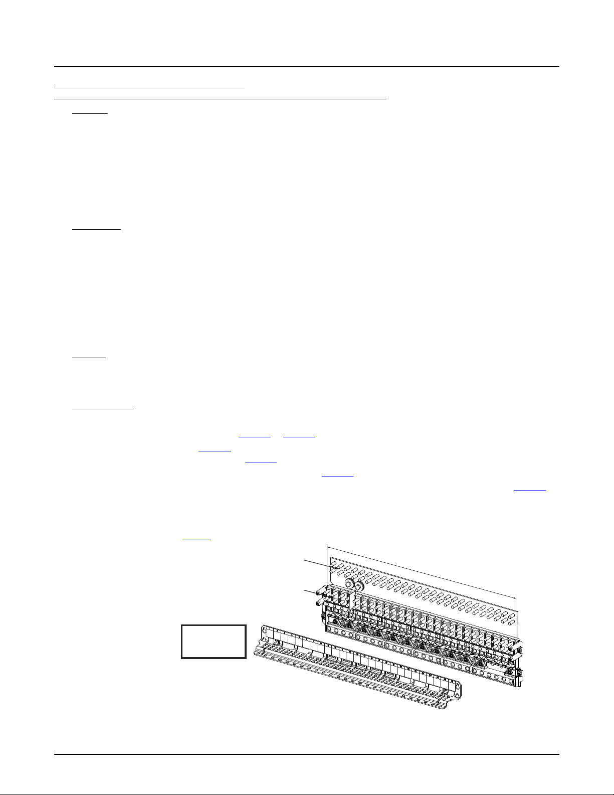
NetSure™ 7100 DC Power System
79
+24
V
D
i
s
tr
i
b
u
ti
o
n
LOAD AND LOAD RETURN CONNECTIONS
1/4-20 Studs on 5/8”Centers
(Customer must supply
or order additional
hardware)
Maximum Lug Width:
0.625 inches.
Load
Connections
Load Return
Connections
Observe proper
polarity when making
load connections.
WARNING!
Caution: 100 A circuitbreakers and fuses can be used without a spaceprovided
the continuous operatingcurrent in each 100 A device does not exceed 64 A.
A 175 A or greater circuit breaker shall have an empty mounting position betweenit
and any other overcurrentprotective device.
System Application Guide
List DK: -48 VDC / +24 VDC Distribution Panel,
(26) +24 VDC Bullet/TPS/TLS Circuit Breaker/Fuse Positions (with Return Busbar)
Features
♦ (26) +24 VDC Load Distribution Fuse / Circuit Breaker Mounting Positions:
3 A to 100 A TPS/TLS Type Fuses,
1 A to 300 A Bullet Nose Type Circuit Breakers.
♦ Includes a return busbar.
♦ 500 A Maximum +24 V Distribution Capacity.
If reconfigured in the field; 600 A Maximum Total Capacity:
600 A Maximum -48 VDC Distribution Capacity.
500 A Maximum +24 VDC Distribution Capacity.
Restrictions
Cannot be used in a supplemental bay.
Limit two (2) dual voltage distribution panels per power system. If two dual voltage distribution panels are ordered, they must
be mounted in adjacent rows. Maximum subsystem current capacity of the second panel is 255 A based on the cables that
are provided to connect it to the first panel.
Can be installed in any row of a 1-, 2-, 3-, or 4-row distribution cabinet.
Unless otherwise specified fuses and/or circuit breakers are mounted from left to right, starting with the highest capacity and
working to the lowest capacity.
125 A, 150 A, 175 A, and 200 A circuit breakers occupy two mounting positions.
225 A, 250 A, and 300 A circuit breakers occupy three mounting positions.
Caution: 100 A circuit breakers and fuses can be used without a space provided the continuous operating current in
each 100 A device does not exceed 64 A. A 175 A or greater circuit breaker shall have an empty mounting
position between it and any other overcurrent protective device.
Maximum lug width, 0.625 inches.
Ordering Notes
1) Specify row for panel location(s).
2) Order circuit breakers as required per Table 14 or Table 15.
3) Order fuses as required per Table 16. Also order one (1) P/N 117201 bullet nose type fuseholder per fuse ordered. Order
replacement alarm fuses (18/100 A) per Table 21.
4) Order 6-position GMT fuse block P/N 549017 and fuses per Table 17 as required.
5) Order load lugs (two hole, 1/4” bolt clearance hole, 5/8” centers) as required for each distribution position per Table 51.
6) Order lug hardware kit (P/N 541084) as required. Lug hardware kit provides thirty-two (32) sets of 1/4-20 hardware
(nuts, flat washers, and lock washers), enough for sixteen (16) lug landing points.
7) When replacing a List AA, AB, AC, AD, AE, AF, AG, AH, AJ, AK, DA, DB, DC, DD, BA, BB, BC, BD, BE, BF, BG, or BH with this
panel; order busbar per Table 5. Existing busbar required to be replaced with this busbar.
Spec. No: 582127000 SAG582127000
Model No: 7100 Revision BJ, August 21, 2020
Page 80
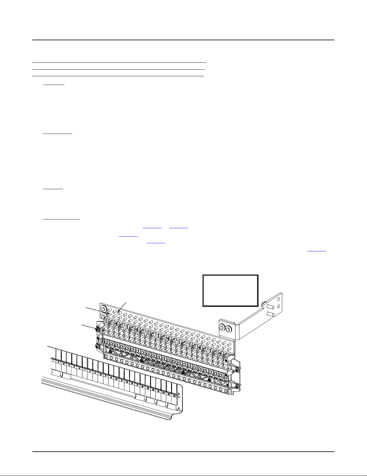
NetSure™ 7100 DC Power System
80
-48VDC Battery
Connections
Battery Return
Connections
BATTERY AND BATTERY RETURN CONNECTIONS
1/4-20 Studs on 5/8” Centers Maximum Lug Width: 0.625 inches.
(Customer must supply
or order additional
hardware)
Return Busbar
(not included with List BB)
Observe proper polarity
when making battery
connections.
WARNING!
Caution: 100 A circuit breakers and fuses can be used without a space
provided the continuous operating current in each 100 A device does
not exceed 64 A. A 175 A or greater circuit breaker shall have an
empty mounting position between it and any other overcurren
protective device.
System Application Guide
Battery Disconnect Distribution Panels
List BA: Battery Disconnect Distribution Panel (with Return Busbar) and
List BB: Battery Disconnect Distribution Panel (without Return Busbar),
(24) Bullet/TPS/TLS Circuit Breaker/Fuse Battery Disconnect Positions
Features
♦ (24) -48 VDC Battery Disconnect Fuse / Circuit Breaker Mounting Positions:
3 A to 100 A TPS/TLS Type Fuses,
1 A to 300 A Bullet Nose Type Circuit Breakers.
♦ List BA includes a return busbar; List BB does not include a return busbar.
♦ 600 A Maximum Capacity.
Restrictions
Cannot be used with List 21.
Must be installed in top row only (limit one battery disconnect distribution panel per distribution cabinet).
Unless otherwise specified fuses and/or circuit breakers are mounted from left to right, starting with the highest capacity and
working to the lowest capacity.
125 A, 150 A, 175 A, and 200 A circuit breakers occupy two mounting positions.
225 A, 250 A, and 300 A circuit breakers occupy three mounting positions.
Caution: 100 A circuit breakers and fuses can be used without a space provided the continuous operating current in
each 100 A device does not exceed 64 A. A 175 A or greater circuit breaker shall have an empty mounting
position between it and any other overcurrent protective device.
Maximum lug width, 0.625 inches.
Ordering Notes
1) Order circuit breakers as required per Table 14 or Table 15.
2) Order fuses as required per Table 16. Also order one (1) P/N 117201 bullet nose type fuseholder per fuse ordered. Order
replacement alarm fuses (18/100 A) per Table 21.
3) Order load lugs (two hole, 1/4” bolt clearance hole, 5/8” centers) as required for each distribution position per Table 51.
4) Order lug hardware kit (P/N 541084) as required. Lug hardware kit provides thirty-two (32) sets of 1/4-20 hardware
(nuts, flat washers, and lock washers), enough for sixteen (16) lug landing points.
Spec. No: 582127000 SAG582127000
Model No: 7100 Revision BJ, August 21, 2020
Page 81
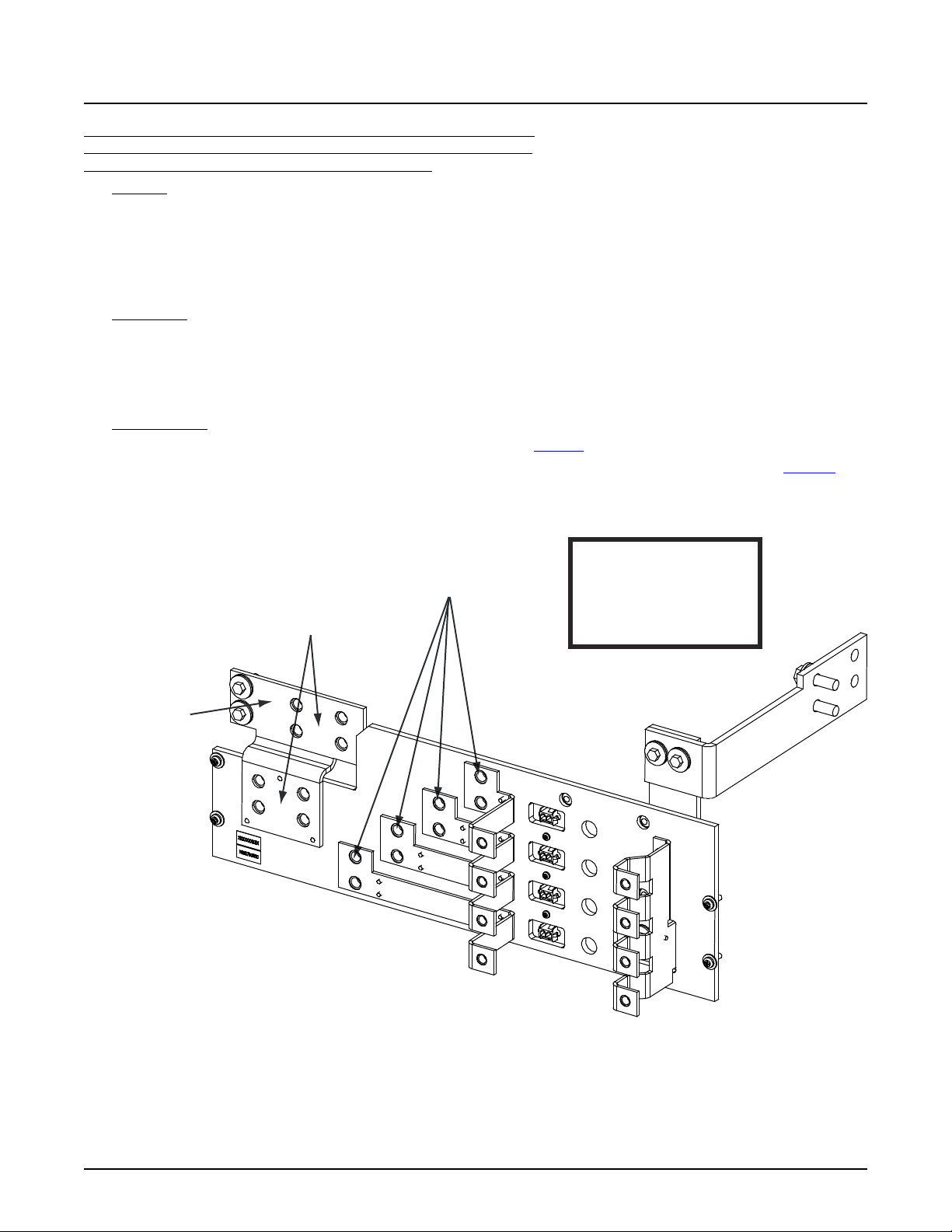
NetSure™ 7100 DC Power System
81
-48VDC Battery
Connections
Battery Return
Connections
BATTERYAND BATTERY RETURN CONNECTI ONS
3/8-16 Captive Nuts on 1” Centers
(Customer must supply
or order additional
hardware)
Maximum Lug Width:
1.375 inches.
Return Busbar
(not included
with List BD)
Observe proper polarity
when making battery
connections.
WARNING!
For an 800A circuit breaker,
load must not exceed 600A.
System Application Guide
List BC: Battery Disconnect Distribution Panel (with Return Busbar) and
List BD: Battery Disconnect Distribution Panel (without Return Busbar),
(4) GJ/218 Circuit Breaker Battery Disconnect Positions
Features
♦ (4) -48 VDC Battery Disconnect Circuit Breaker Mounting Positions:
100 A to 800 A GJ/218 Type Circuit Breakers.
♦ List BC Includes a return busbar; List BD does not include a return busbar.
♦ 600 A Maximum Capacity.
Maximum current rating of each landing point is 360 A.
Restrictions
Cannot be used with List 21.
Must be installed in top row only (limit one battery disconnect panel per distribution cabinet).
Maximum lug width, 1.375 inches.
For an 800 A circuit breaker, load must not exceed 600 A.
Ordering Notes
1) Order circuit breakers and associated jumper kits as required per Table 18.
2) Order load lugs (two hole, 3/8” bolt clearance hole, 1” centers) as required for each distribution position per Table 52.
3) Order lug hardware kit (P/N 548184) as required. Lug hardware kit provides sixteen (16) sets of 3/8-16 hardware (bolts,
flat washers, and lock washers), enough for eight (8) lug landing points.
Spec. No: 582127000 SAG582127000
Model No: 7100 Revision BJ, August 21, 2020
Page 82
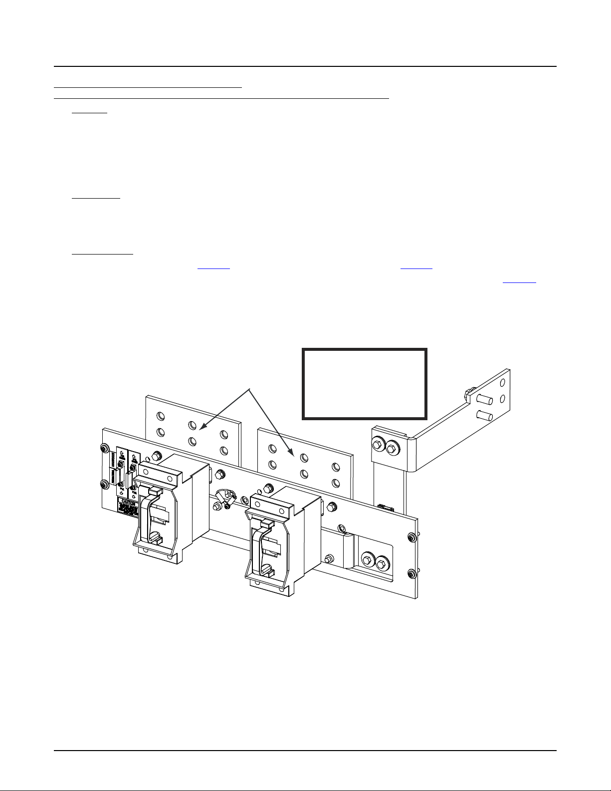
NetSure™ 7100 DC Power System
82
-48VDC Battery
Connections
BATTERY CONNECTIO NS
3/8-16 Captive Nuts on 1” Centers Maximu m Lu g Width: 1.88 inches.
(Customer must supply
or order additional
hardware)
Observe proper polarity
when making battery
connections.
WARNING!
System Application Guide
List BE: Battery Disconnect Distribution Panel,
(2) TPH Fuse Battery Disconnect Position (without Shunts) (without Return Busbar)
Features
♦ (2) -48 VDC Battery Disconnect Fuse Mounting Positions:
70 A to 600 A TPH Type Fuses.
♦ Does NOT include shunts.
♦ Does NOT include a return busbar.
♦ 1200 A Maximum Capacity.
Restrictions
Cannot be used with List 21.
Must be installed in top row only (limit one battery disconnect panel per distribution cabinet).
Maximum lug width, 1.88 inches.
Ordering Notes
1) Order fuses as required per Table 19. Order replacement alarm fuses (1/4 A) per Table 21.
2) Order load lugs (two hole, 3/8” bolt clearance hole, 1” centers) as required for each distribution position per Table 52.
3) Order lug hardware kit (P/N 548184) as required. Lug hardware kit provides sixteen (16) sets of 3/8-16 hardware (bolts,
flat washers, and lock washers), enough for eight (8) lug landing points.
Spec. No: 582127000 SAG582127000
Model No: 7100 Revision BJ, August 21, 2020
Page 83
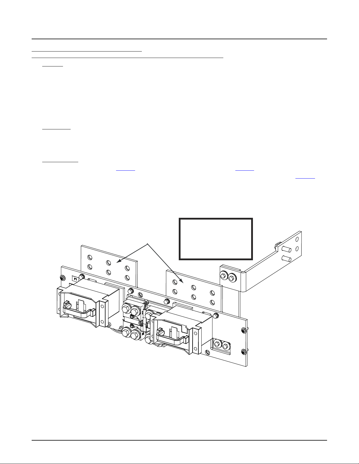
NetSure™ 7100 DC Power System
83
BATTERY CONNECTIO NS
3/8-16 Captive Nuts on 1” Centers Maximum Lug Width: 1.88 inches.
(Customer must supply
or order additional
hardware)
System Application Guide
List BF: Battery Disconnect Distribution Panel,
(2) TPH Fuse Battery Disconnect Positions (with Shunts) (without Return Busbar)
Features
♦ (2) -48 VDC Battery Disconnect Fuse Mounting Positions:
70 A to 600 A TPH Type Fuses.
♦ Includes shunts, 800 A / 25 mV. Each shunt is equipped with 10’ jumpers for connection to monitoring device. If the
system is equipped with an SM-DU+, the leads are trimmed and connected to the SM-DU+ (internal to the distribution
cabinet).
♦ Does NOT include a return busbar.
♦ 1200 A Maximum Capacity.
Restrictions
Cannot be used with List 21.
Must be installed in top row only (limit one battery disconnect panel per distribution cabinet).
Maximum lug width, 1.88 inches.
Ordering Notes
1) Order fuses as required per Table 19. Order replacement alarm fuses (1/4 A) per Table 21.
2) Order load lugs (two hole, 3/8” bolt clearance hole, 1” centers) as required for each distribution position per Table 52.
3) Order lug hardware kit (P/N 548184) as required. Lug hardware kit provides sixteen (16) sets of 3/8-16 hardware (bolts,
flat washers, and lock washers), enough for eight (8) lug landing points.
-48VDC Battery
Connections
Observe proper polarity
when making battery
connections.
WARNING!
Spec. No: 582127000 SAG582127000
Model No: 7100 Revision BJ, August 21, 2020
Page 84
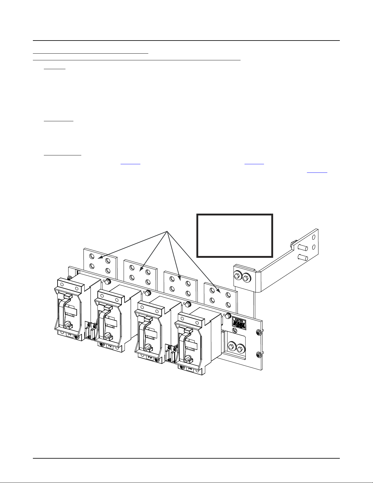
NetSure™ 7100 DC Power System
84
-48VDC Battery
Connections
BATTERY CONNECTIO NS
3/8-16 Captive Nuts on 1” Centers
(Customer must supply
or order additional
hardware)
Observe proper polarity
when making battery
connections.
WARNING!
Maximum Lug Width: 1.75 inches.
Maximum fuse size is 400A.
System Application Guide
List BG: Battery Disconnect Distribution Panel,
(4) TPH Fuse Battery Disconnect Positions (without Shunts) (without Return Busbar)
Features
♦ (4) -48 VDC Battery Disconnect Fuse Mounting Positions:
70 A to 400 A TPH Type Fuses.
♦ Does NOT include shunts.
♦ Does NOT include a return busbar.
♦ 1200 A Maximum Capacity.
Restrictions
Cannot be used with List 21.
Must be installed in top row only (limit one battery disconnect panel per distribution cabinet).
Maximum lug width, 1.75 inches.
Ordering Notes
1) Order fuses as required per Table 19. Order replacement alarm fuses (1/4 A) per Table 21.
2) Order load lugs (two hole, 3/8” bolt clearance hole, 1” centers) as required for each distribution position per Table 52.
3) Order lug hardware kit (P/N 548184) as required. Lug hardware kit provides sixteen (16) sets of 3/8-16 hardware (bolts,
flat washers, and lock washers), enough for eight (8) lug landing points.
Spec. No: 582127000 SAG582127000
Model No: 7100 Revision BJ, August 21, 2020
Page 85
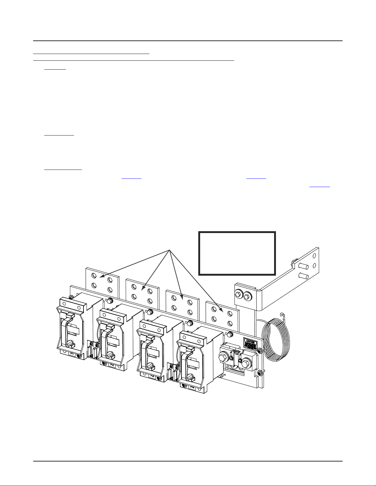
NetSure™ 7100 DC Power System
85
BATTERY CONNECTIONS
Maximum Lug Width: 1.75 inches.
System Application Guide
List BH: Battery Disconnect Distribution Panel,
(4) TPH Fuse Battery Disconnect Positions (with Shunts) (without Return Busbar)
Features
♦ (4) -48 VDC Battery Disconnect Fuse Mounting Positions:
70 A to 400 A TPH Type Fuses.
♦ Includes shunts, 600 A / 25 mV. Each shunt is equipped with 10’ jumpers for connection to monitoring device. If the
system is equipped with an SM-DU+, the leads are trimmed and connected to the SM-DU+ (internal to the distribution
cabinet).
♦ Does NOT include a return busbar.
♦ 1200 A Maximum Capacity.
Restrictions
Cannot be used with List 21.
Must be installed in top row only (limit one battery disconnect panel per distribution cabinet).
Maximum lug width, 1.75 inches.
Ordering Notes
1) Order fuses as required per Table 19. Order replacement alarm fuses (1/4 A) per Table 21.
2) Order load lugs (two hole, 3/8” bolt clearance hole, 1” centers) as required for each distribution position per Table 52.
3) Order lug hardware kit (P/N 548184) as required. Lug hardware kit provides sixteen (16) sets of 3/8-16 hardware (bolts,
flat washers, and lock washers), enough for eight (8) lug landing points.
3/8-16 Captive Nuts on 1” Centers
(Customer must supply
or order additional
hardware)
Maximum fuse size is 400A.
-48VDC Battery
Connections
Observe proper polarity
when making battery
connections.
WARNING!
Spec. No: 582127000 SAG582127000
Model No: 7100 Revision BJ, August 21, 2020
Page 86
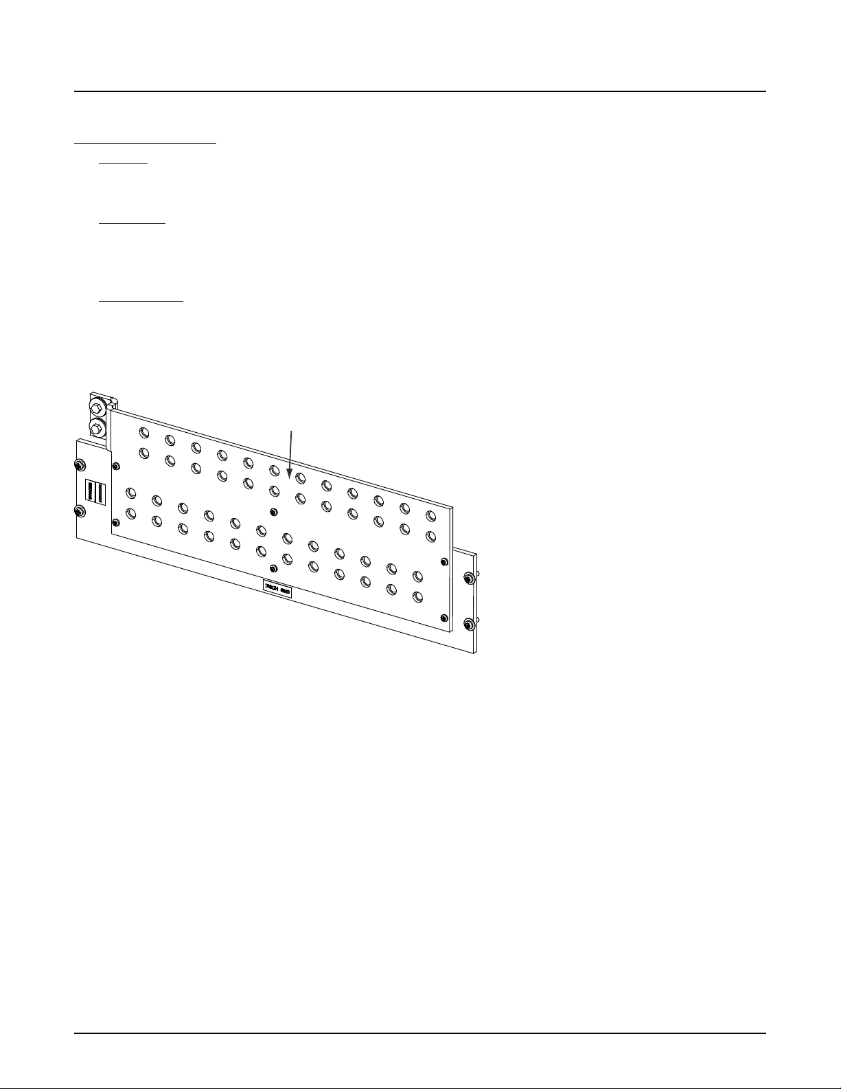
NetSure™ 7100 DC Power System
86
Load and/or Battery
Return Connections
LOAD AND/OR BATTERY RETURN CONNECTIONS
3/8-16 Captive Nuts on 1” Centers
(Customer must su pply or order additional hardware)
Maximum Lug Width: 1.38 inches.
System Application Guide
Return Bar Panel
List GA: Return Bar Panel
Features
♦ Return bar panel for use with distribution panels when internal load returns are required.
♦ 1200 A Maximum Capacity.
Restrictions
Cannot be used in a 1- row distribution cabinet.
Can be installed in any row 1-4 of a 2-, 3-, or 4-row distribution cabinet.
Maximum lug width, 1.38 inches.
Ordering Notes
1) Specify row for panel location(s).
2) To terminate load and/or battery returns within the distribution cabinet, order List GA as required.
3) Order lug hardware kit (P/N 548184) as required. Lug hardware kit provides sixteen (16) sets of 3/8-16 hardware (bolts,
flat washers, and lock washers), enough for eight (8) lug landing points.
Spec. No: 582127000 SAG582127000
Model No: 7100 Revision BJ, August 21, 2020
Page 87
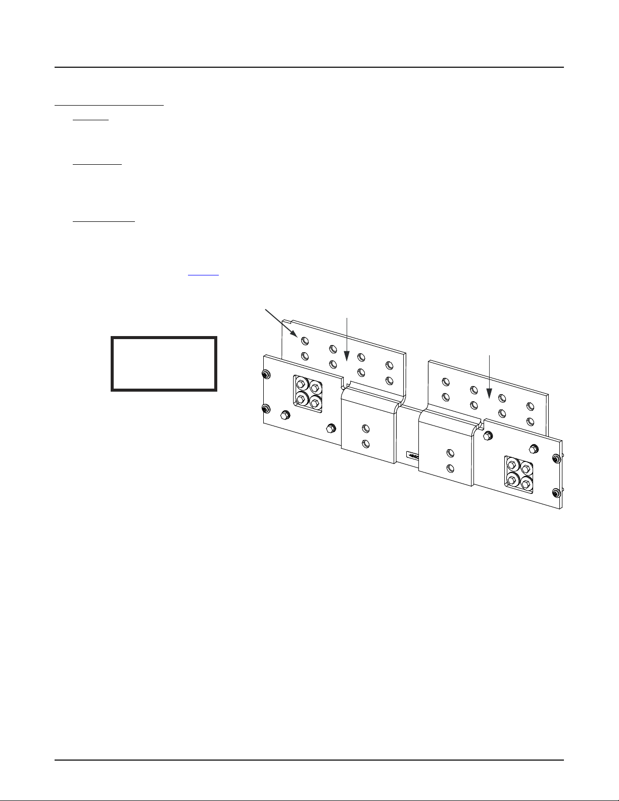
NetSure™ 7100 DC Power System
87
Observe proper
polarity when making
load connections.
WARNING!
Load Return
Connections
LOAD AND LOAD RETURN CONNECTIONS
3/8-16 Captive Nuts on 1” Centers
(Customer must supply or order additional h ar dware)
Maximum Lug Width: 2.0 inches.
Return Busbar
-48 VDC Load
Connections
System Application Guide
Bulk Output Panel
List EA: Bulk Output Panel
Features
♦ Provides a bulk output panel with five (5) landing points per polarity.
♦ 1600 A Maximum Capacity.
Restrictions
Not available with List 21 (1-row cabinet).
List LL is not available in any row if the system is equipped with one or more List EA, List AM, or List AP.
Maximum lug width, 2.0 inches.
Ordering Notes
1) Order as required.
2) Specify row for panel location(s).
3) When replacing a List AA, AB, AC, AD, AE, AF, AG, AH, AJ, AK, DA, DB, DC, DD, BA, BB, BC, BD, BE, BF, BG, or BH with this
panel; order busbars per Table 7. Existing busbars required to be replaced with these busbars.
Spec. No: 582127000 SAG582127000
Model No: 7100 Revision BJ, August 21, 2020
Page 88

NetSure™ 7100 DC Power System
88
System Application Guide
When replacing a List AA, AB, AC, AD, AE, AF, AG, AH, AJ, AK, DA, DB, DC, DD, BA, BB, BC, BD, BE, BF, BG, or BH with List EA,
remove one (1) hot side and one (1) return side busbar from corresponding position and replace with new busbars ordered
from Table 7.
4-Row Distribution Cabinet without LVLD
Existing Busbar New Busbar
Row Return Side Hot Side Row Return Side Hot Side
4 548274 561774 4 562469 562473
3 548273 561773 3 562470 562474
2 548272 561772 2 562471 562475
1 548271 562822 1 562472 562476
3-Row Distribution Cabinet without LVLD
Existing Busbar New Busbar
Row Return Side Hot Side Row Return Side Hot Side
3 548274 561774 3 562469 562473
2 548272 561881 2 562477 562452
1 548271 562822 1 562472 562476
2-Row Distribution Cabinet without LVLD
Existing Busbar New Busbar
Row Return Side Hot Side Row Return Side Hot Side
2 548273 561773 2 562470 562474
1 548271 562822 1 562472 562476
Table 7
Spec. No: 582127000 SAG582127000
Model No: 7100 Revision BJ, August 21, 2020
Page 89

NetSure™ 7100 DC Power System
89
System Application Guide
Battery Disconnect Contactors
List CA: 600 A Battery Disconnect Contactor
Features
♦ Provides a battery disconnect contactor which is mounted within the main bay distribution cabinet.
Restrictions
Main bay only.
Must be used with List LB, MB, or both.
For use with List 21 only.
Can only use LVLD or LVBD on List 21, not both.
Ordering Notes
1) Order as required.
List CB: 1200 A Battery Disconnect Contactor
Features
♦ Provides a battery disconnect contactor which is mounted within the main bay distribution cabinet.
Restrictions
Main bay only.
Must be used with List LB, MB, or both.
For use with List 22, 23, or 24 only.
If used in List 23 or 24, system capacity is reduced to 1200 A.
Ordering Notes
1) Order as required.
List CC: 2000 A Battery Disconnect Contactor
Features
♦ Provides a battery disconnect contactor which is mounted within the main bay distribution cabinet.
Restrictions
Main bay only.
Must be used with List LB, MB, or both.
For use with List 22, 23, or 24 only.
Ordering Notes
1) Order as required.
Spec. No: 582127000 SAG582127000
Model No: 7100 Revision BJ, August 21, 2020
Page 90
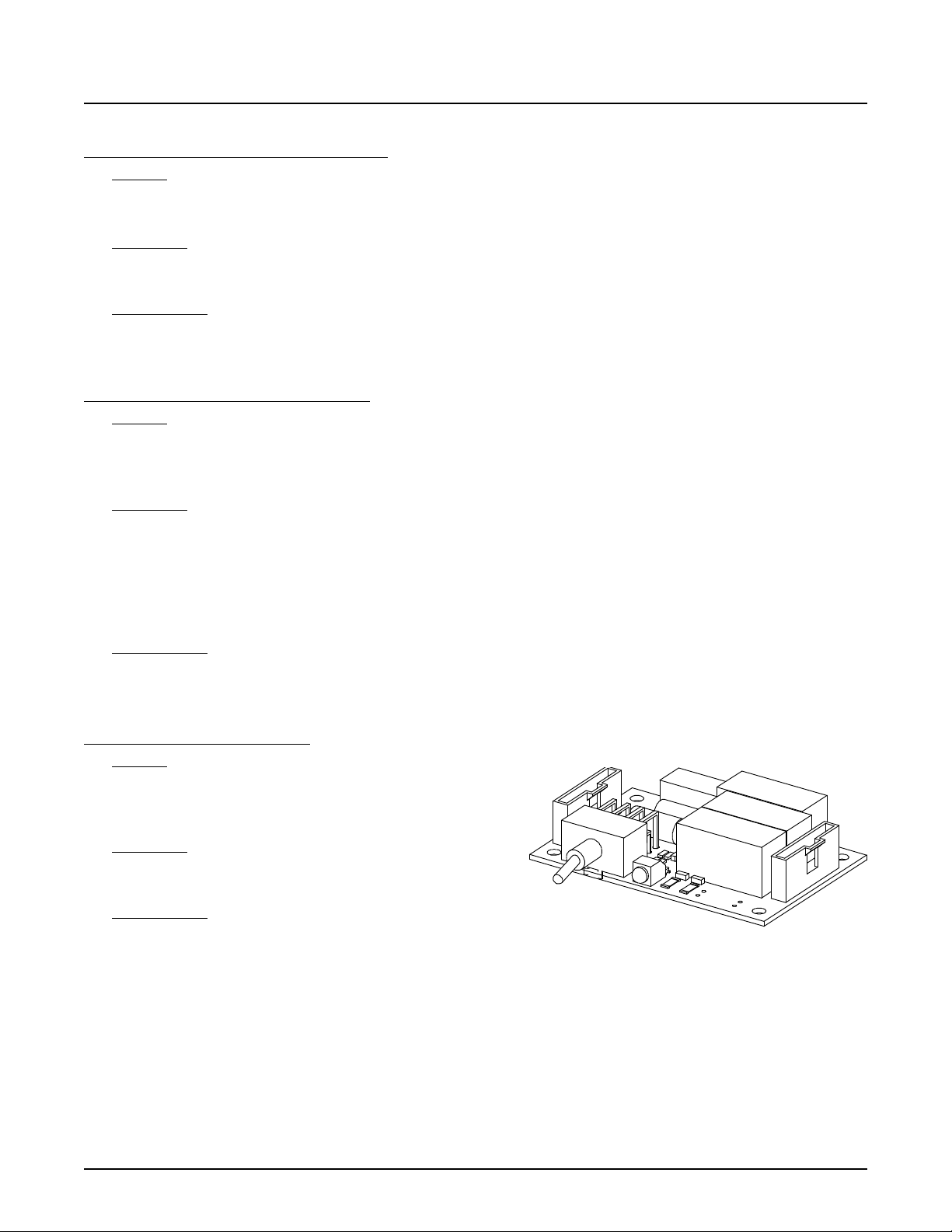
NetSure™ 7100 DC Power System
90
System Application Guide
Low Voltage Disconnect Options
List LB: Low Voltage Battery Disconnect (LVBD)
Features
♦ Adds Low Voltage Battery Disconnect (LVBD) to the system.
♦ Adds LVD Driver circuit card P/N 563696 or LVD Driver Lite circuit card P/N 547873 to the main bay distribution cabinet.
Restrictions
Must be used with List CA, CB, or CC.
Installed in main bay only.
Ordering Notes
1) Order if low voltage battery disconnect (LVBD) is required.
2) Can be combined with manual battery disconnect (List MB) if required.
List LL: Low Voltage Load Disconnect (LVLD)
Features
♦ Adds low voltage load disconnect (LVLD) to a distribution panel.
♦ Adds LVD Driver circuit card P/N 563696 (main bay) / 563718 (supplemental bay) or LVD Driver Lite circuit card P/N
547873 (main bay) / 547874 (supplemental bay) to a distribution cabinet, one per distribution cabinet.
Restrictions
Must be used with List AA through AL, AN, DA through DJ. Not available with Lists AM, AP, DK or EA.
In a List 22, List 23, List 24; the List LL Low Voltage Load Disconnect (LVLD) option cannot be installed in the field for
systems that are not equipped with any LVLD’s from the factory. Field replacement of factory installed LVLD contactors is
still available.
Cannot use List LL in row 1 if row 1 is equipped with List DJ.
Capacity is reduced to 500 amps for any row equipped with List LL.
Ordering Notes
1) Order low voltage load disconnect (LVLD) per load distribution panel (one per row) as required. Specify by row.
Manual Battery Disconnect Option
List MB: Manual Battery Disconnect
Features
♦ Adds manual battery disconnect to the system.
♦ Adds manual disconnect circuit card P/N 540973 to the
system.
Restrictions
Must be used with List CA, CB, or CC.
Installed in main bay only.
Ordering Notes
1) Order if manual battery disconnect is required.
2) Can be combined with low voltage battery disconnect (List LB) if required.
Spec. No: 582127000 SAG582127000
Model No: 7100 Revision BJ, August 21, 2020
Page 91
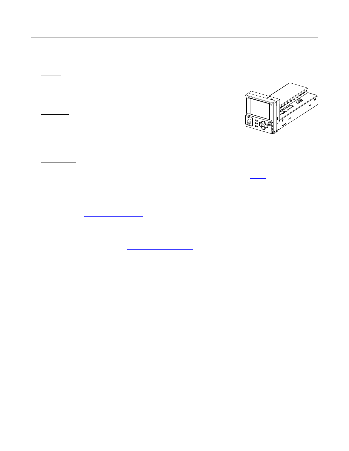
NetSure™ 7100 DC Power System
91
System Application Guide
ACCESSORY DESCRIPTIONS
Controller
NCU (NetSure Control Unit) Controller, P/N 1M830DNA
Features
♦ Provides one (1) Model M830DNA, Spec. No. 1M830DNA system controller.
♦ Factory programmed with the configuration file required for the system configuration
ordered.
Note:
For custom NCU configurations, contact Vertiv.
Restrictions
Only one (1) controller per power system is required.
Mounts in the main bay (List 1) distribution cabinet.
Cannot be installed in a List 2, List 3, List 5, List 7, or List 8 supplemental bay.
Cannot be used with DC-DC Converter Modules P/N 1C400483500e.
The system can contain only three (3) Interface Boards, (1) IB2 and (2) EIB or (2) EIB and (1) IB2.
Ordering Notes
1) Order one (1) controller (P/N 1M830DNA) per power system.
2) If the NCU Controller (1M830DNA) is ordered, order a “2nd Ethernet Port Add-On Kit” P/N 559252 if required. For
retrofitting into older bays, order “2nd Ethernet Port Retrofit Kit” P/N 559251.
3) Order the optional second IB2 controller interface board as required. See Restrictions. See page 92.
4) Order the optional EIB controller extended interface board as required (see page 93).
5) Order the optional second EIB extended interface board as required. See page. See page 93.
6) Order optional SM-DU+ Shunt Monitoring (P/N 548078) for any fuse panel with shunts (Lists AF, AH, AK, BF, or BH) or
any GJ/218 panels (Lists AC, AD, BC, BD, AM, or AP) that are equipped with shunted breakers. (The SM-DU+ is factorywired to the shunts.)
7) Order optional temperature probes for ambient and battery temperature monitoring, as required. The temperature
probe(s) may also be used for the battery charge temperature compensation feature and BTRM (Battery Thermal
Runaway Management). Refer to “Optional Temperature Probes” for additional information.
8) Order optional SM-Temp Temperature Concentrator (Supervisory Module for Temperature Probes) as desired (shipped
loose) (see page 96).
Note:
A system can have up to (8) SM-Temp modules (each of which can accept up to eight temperature probes)
that can be used in the power system for ambient and battery monitoring.
9) Ordering an NCU for replacing an NCU or as a spare NCU.
If the NCU is to be used as a replacement in a specific system it should be ordered with the same configuration file as the
original NCU controller. This is identified by a six digit number. If the controller part number ends with a six digit
number, for example, 1M830BNA559242, the configuration file number is the last six characters. If the part number does
not have these characters, the configuration file number can be found on the controller nameplate – “Programmed with
Configuration File ######”. The controller may also have a Unique Identification Number (UIN). This number indicates
that certain parameters were set at the factory to match the controller to the options selected with the power plant (such
as low voltage disconnect, load and battery shunt ratings, etc.). If the controller has a UIN, the plant will have shipped
with a USB drive labelled with the UIN. The UIN label may also be located near the controller slot in the system. If the
controller has a UIN, provide this UIN number, along with the configuration number, when ordering so that the new
controller will match that of the original controller shipped with the system. The user manual provided with the controller
provides instructions for replacing and programming the controller. It is important to follow these instructions carefully.
The user manual also provides instructions for saving certain controller files that are created when changes are made to
the system after leaving the factory. These files can be programmed into the replacement controller so it can match the
latest saved state of the original controller.
If the NCU is being ordered as a spare part for any of a group of power plants, the same procedure can be followed. If the
replacement controller’s configuration does not match that of the original controller, the original files can be retrieved
from the USB drive shipped with the plant, if available. If the USB drive is not available, contact the factory or technical
assistance center to obtain a copy of the original configuration file (all package) so it can be programmed into the new
controller.
Spec. No: 582127000 SAG582127000
Model No: 7100 Revision BJ, August 21, 2020
Page 92
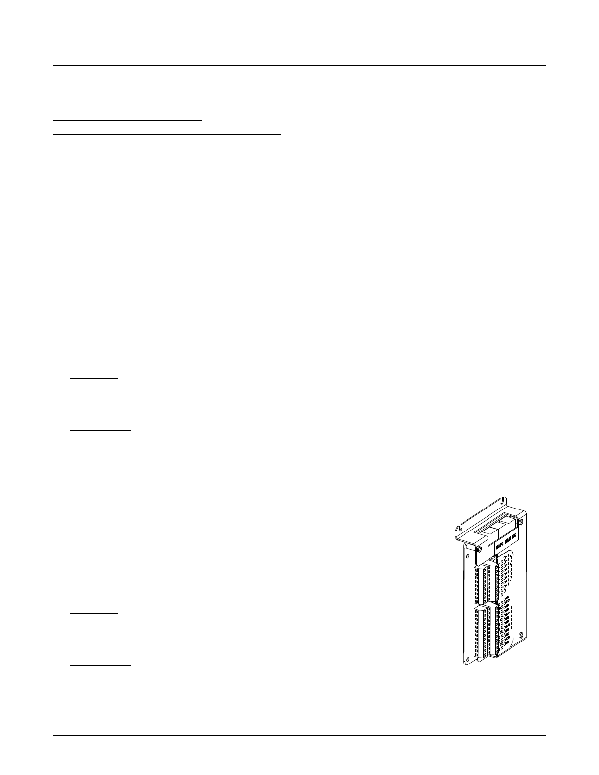
NetSure™ 7100 DC Power System
92
System Application Guide
The NCU programming files are unique to the NCU. Files from an SCU+ or ACU+ are not compatible with the NCU and
MUST NOT BE loaded into an NCU.
NCU Controller 2nd Ethernet Port Kits
NCU Controller 2nd Ethernet Port Add-On Kit, P/N 559252
Features
♦ Provides the IB4 board with a second Ethernet port. The Ethernet port located on the NCU Controller’s front panel can
be used to connect a computer directly to the NCU. The Ethernet port located on the IB4 board can be used to connect
the NCU to your Local Area Network (LAN).
Restrictions
For use only with NCU controller, not the ACU+ controller. Factory installed in a main bay if initially ordered with the power
system. Field installable only into a main bay if initially ordered with the NCU controller.
Not for use in List 100, 101, 102, 103, 203.
Ordering Notes
1) If a second Ethernet port is required, order kit P/N 559252. For field upgrade of systems originally configured with the
ACU+ controller, order kit P/N 559251. The field upgrade must also include the NCU controller replacing the ACU+
controller.
NCU Controller 2nd Ethernet Port Retrofit Kit, P/N 559251
Features
♦ Provides a complete control module assembly that allows an IB4 board to be connected to the NCU in an older main bay.
♦ Provides the IB4 board with a second Ethernet port. The Ethernet port located on the NCU Controller’s front panel can
be used to connect a computer directly to the NCU. The Ethernet port located on the IB4 board can be used to connect
the NCU to your Local Area Network (LAN).
Restrictions
Field installable only into a main bay if initially ordered with the ACU+ controller. The field upgrade must also include the
NCU controller replacing the ACU+ controller.
Not for use in List 100, 101, 102, 103, 203.
Ordering Notes
1) For field upgrade of systems originally configured with the ACU+ controller, order kit P/N 559251. The field upgrade
must also include the NCU controller replacing the ACU+ controller.
Optional Second IB2 (Controller Interface Board), P/N 555286 or MA4C5U31
Features
♦ Provides connections for up to two (2) temperature probes.
♦ Provides connections for the eight (8) programmable form C- relay outputs located on the
board.
♦ Provides connections for the eight (8) programmable binary digital inputs located on the
board.
Note:
An IB2 (Controller Interface Board) is factory provided with the system. The IB2
provides eight (8) programmable form C- relay outputs, eight (8) programmable
binary digital inputs and two (2) temperature inputs.
Restrictions
A second IB2 or EIB controller interface board requires an NCU not an ACU+. The system can
contain only three (3) interface boards, (1) IB2 and (2) EIB or (2) IB2 and (1) EIB.
Must be installed in the main bay.
Ordering Notes
1) Order a second optional IB2 Interface Board Assembly (P/N 555286 for List 1 or MA4C5U31 for Lists 100, 101, 102, 103 and
203) per system as required. Also, order up to two (2) additional temperature probes, as desired.
2) Refer to “In-Line Fuse and Resistor Pigtail Kits” on page 93 for in-line resistor pigtails for use with shunt inputs and in-
line fuse for sure with battery midpoint inputs.
Spec. No: 582127000 SAG582127000
Model No: 7100 Revision BJ, August 21, 2020
Page 93
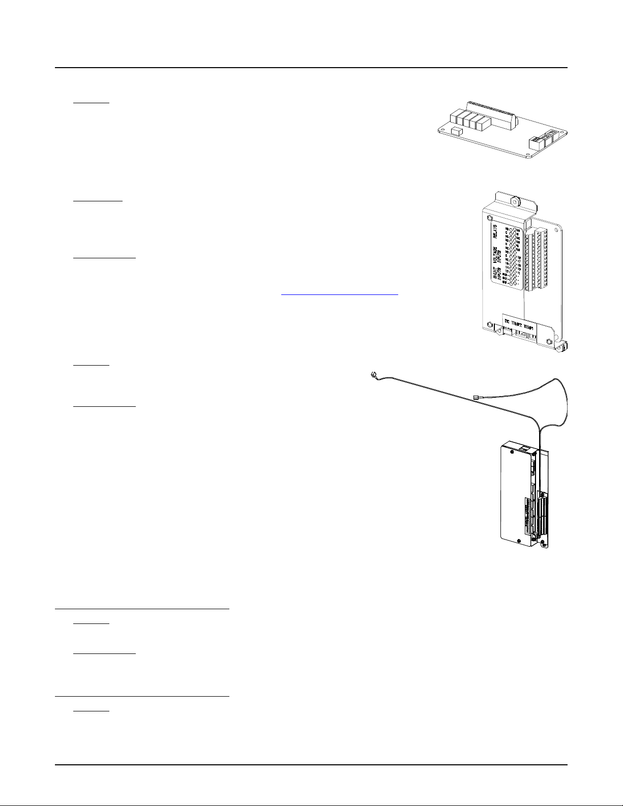
NetSure™ 7100 DC Power System
93
RLY02RLY05
RLY01
RLY04
RLY03
System Application Guide
Optional EIB-1 and EIB-2 (Controller Extended Interface Board), P/N 548120 and MA455U41
Features
♦ Provides connections for up to two (2) temperature probes.
♦ Provides connections for the five (5) programmable form C- relay outputs located on
the board.
♦ Provides connections for the three (3) shunt inputs located on the board. Shunts
must be installed in the hot (-48V) bus.
♦ Provides connections for the eight (8) battery midpoint inputs located on the board.
Restrictions
The system can contain only three (3) interface boards, (1) IB2 and (2) EIB or (2) IB2 and (1) EIB.
Note:
A second IB2 or EIB controller interface board requires an NCU not an ACU+.
The Optional Second EIB must be installed in the main bay.
Ordering Notes
1) Order by P/N 548120 (all Lists except List 100, 101, 102, 103, 203) or P/N MA455U41 (List 100, 101,
102, 103, 203) as required. Must be ordered if ordering converters. Also order up to two (2)
additional temperature probes, as desired. See “Optional Temperature Probes”.
2) Refer to “In-Line Fuse and Resistor Pigtail Kits” on page 93 for in-line resistor pigtails for use with
shunt inputs and in-line fuse pigtails for use with battery midpoint inputs.
Optional SM-DU+ Shunt Monitoring, P/N 548078
Features
♦ Provides twenty-five (25) shunt monitoring inputs. Shunts must be
installed in the hot (-48V) bus.
Ordering Notes
1) Order optional SM-DU+ Shunt Monitoring for any fuse panel with
shunts (Lists AF, AH, AK, BF, or BH) or any GJ/218 panels (Lists AC,
AD, BC, BD, AM, or AP) that are equipped with shunted breakers.
(The SM-DU+ is factory-wired to the shunts.) Order by P/N 548078
as required.
2) Refer to “In-Line Fuse and Resistor Pigtail Kits” on page 93 for in-
line resistor pigtails for use with shunt inputs and in-line fuse pigtails
for use with battery midpoint inputs.
In-Line Fuse and Resistor Pigtail Kits
In-line fuse kits should be used for connecting to battery or bus
potentials for use with the digital inputs on the IB2 Interface Board and
the battery midpoint/block voltage inputs on the EIB Extended Interface Board. In-line resistor kits should be used for
connecting to shunts for use with the EIB Extended Interface Board and SMDU+ Shunt Interface Board.
1 A In-Line Fuse Pigtail Kit, P/N 431300200
Features
♦ In-line fuse pigtail kit with 3/8” ring lug.
Ordering Notes
1) Order Kit P/N 431300200, as required.
1 A In-Line Fuse Pigtail Kit, P/N 431300300
Features
♦ In-line fuse pigtail kit with 5/16” ring lug.
Spec. No: 582127000 SAG582127000
Model No: 7100 Revision BJ, August 21, 2020
Page 94

NetSure™ 7100 DC Power System
94
System Application Guide
Ordering Notes
1) Order Kit P/N 431300300, as required.
1 A In-Line Fuse Pigtail Kit, P/N 535135
Features
♦ In-line fuse pigtail kit with a splice connector, 3/8” ring lug, and 1/4” ring lug.
Ordering Notes
1) Order Kit P/N 535135, as required.
49.9 Ohm In-Line Resistor Pigtail Kit, P/N 424227900
Features
♦ In-line resistor pigtail kit with 3/8” ring lug.
Ordering Notes
1) Order Kit P/N 424227900, as required.
49.9 Ohm In-Line Resistor Pigtail Kit, P/N 424228000
Features
♦ In-line resistor pigtail kit with a splice connector.
Ordering Notes
1) Order Kit P/N 424228000, as required.
49.9 Ohm In-Line Resistor Pigtail Kit, P/N 424228100
Features
♦ In-line resistor pigtail kit with 5/16” ring lug.
Ordering Notes
1) Order Kit P/N 424228100, as required.
Optional Temperature Probes
Features
♦ Up to two (2) temperature probes can be connected to each IB2 (Controller Interface Board). Up to two (2) temperature
probes can be connected to each EIB (Controller Extended Interface Board). Up to two (2) temperature probes can be
connected to the System Interface Board (List 100, 101, 102, 103, and 203 only). Any combination of the temperature
probes can be programmed to monitor ambient temperature and/or battery temperature. A temperature probe set to
monitor battery temperature can also be used for the rectifier battery charge temperature compensation feature, or the
battery charge temperature compensation feature can be programmed to use the average or highest value of all battery
temperature probes. The battery charge temperature compensation feature allows the controller to automatically
increase or decrease the output voltage of the system to maintain battery float current as battery temperature decreases
or increases, respectively. Battery life can be extended when an optimum charge voltage to the battery with respect to
temperature is maintained. A temperature probe set to monitor battery temperature can also be used for the BTRM
(Battery Thermal Runaway Management) feature. The BTRM feature lowers output voltage when a high temperature
condition exists to control against battery thermal runaway.
♦ The temperature sensor end of the probe contains a tab with a 5/16” clearance hole for mounting.
♦ Temperature probes can also be used with the optional SM-Temp Temperature Concentrator.
Restrictions
A temperature probe programmed to monitor battery temperature should be mounted on the negative post of a battery cell
to sense battery temperature. A temperature probe used for battery charge temperature compensation or BTRM (Battery
Thermal Runaway Management) should also be mounted on the negative post of a battery cell. A temperature probe
programmed to monitor ambient temperature should be mounted in a convenient location, away from direct sources of heat
or cold.
Spec. No: 582127000 SAG582127000
Model No: 7100 Revision BJ, August 21, 2020
Page 95
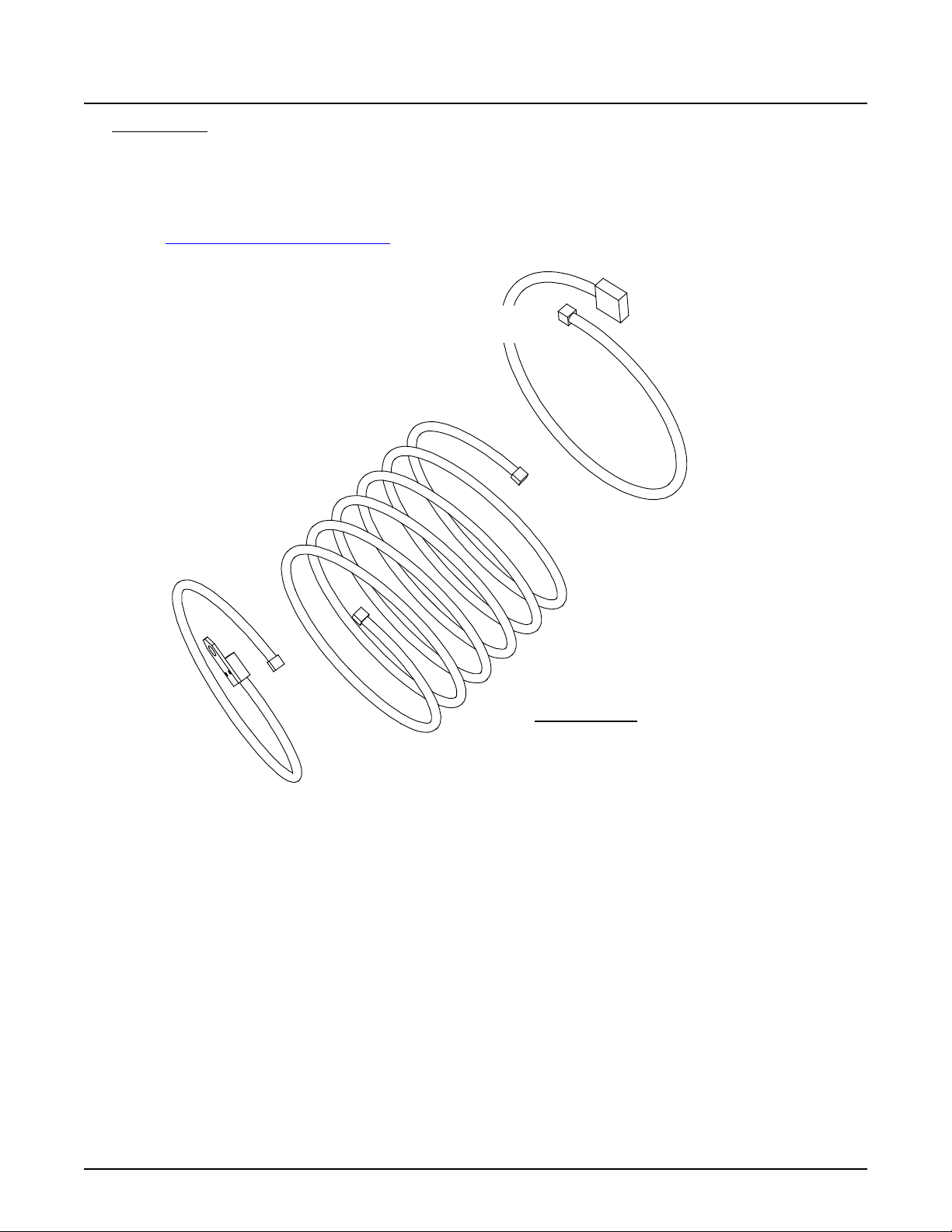
NetSure™ 7100 DC Power System
95
Temp Probe Kits
P/N 552992 (includes P/Ns 552822 and 552823)
P/N 556155 (includes P/Ns 552822 and 556154)
to Controller
Interface Board
P/N 552823 (10 meter length,
approx. 33 feet) Temp Probe
Controller Side Cable
or
P/N 556154 (3 meter length,
approx. 10 feet) Temp Probe
Controller Side Cable
P/N 04119122
(10 meter length,
approx. 33 feet)
optional Temp Probe
Extension Cable
P/N 552822
(0.3 meter length,
approx. 1 feet)
Temp Probe
with Short Cable
to Temp Probe
or Temp Probe Extens ion
System Application Guide
Ordering Notes
1) Order temperature probes as required. Note that each temperature probe consists of two or three pieces which plug
together to make a complete probe (see the following illustration). For a complete temperature probe, order one (1) P/N
552992 (10.3 meters) or one (1) P/N 556155 (3.3 meters). If additional length is required, order temperature probe
extension cable P/N 04119122 (10 meters).
2) If more probes are desired, order one or more SM-Temp Temperature Concentrator, P/N 547490.
See SM-Temp Temperature Concentrator.
Spec. No: 582127000 SAG582127000
Model No: 7100 Revision BJ, August 21, 2020
Page 96
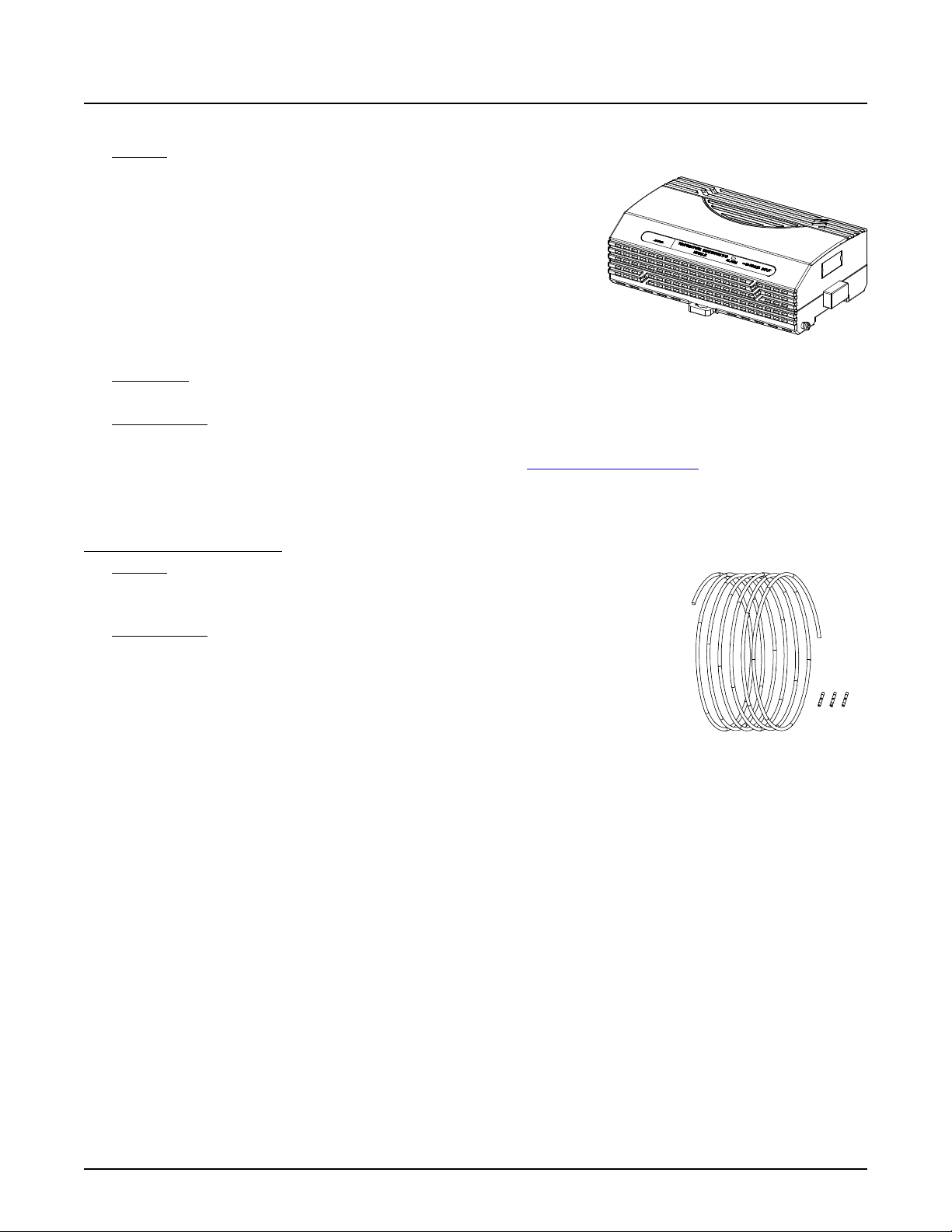
NetSure™ 7100 DC Power System
96
System Application Guide
Optional SM-Temp Temperature Concentrator, P/N 547490
Features
♦ Allows for multiple temperature probes to be used for ambient temperature
monitoring, battery temperature monitoring, temperature compensation,
and/or BTRM (Battery Thermal Runaway Management).
♦ Provides (8) temperature probe inputs per SM-Temp unit.
♦ Can cascade up to (8) SM-Temp units, connecting up to sixty-four (64)
temperature probes.
♦ The SM-Temp Concentrator is connected at the end of the Controller’s
CAN Bus. Via the CAN Bus, the controller reads each temperature probe
from each SM-Temp Concentrator.
♦ Refer to the SM-Temp Temperature Concentrator Instructions (UM547490) for more information.
Restrictions
Requires ACU+ version 3.02 or later when SM-Temp is connected into the ACU+ CAN Bus.
Ordering Notes
1) Order SM-Temp Temperature Concentrator, P/N 547490, as required.
2) Order up to (8) temperature probes for each concentrator. See “Optional Temperature Probe” above.
3) Order one (1) SM-Temp CAN Bus Interface Cable, P/N 562868, to connect the SM-Temp into the controller’s CAN bus.
4) Order SM-Temp jumpers (P/N 552888) to interconnect SM-Temp units, as required. See “SM-Temp Jumpers, P/N
552888” on page 96.
SM-Temp Jumpers, P/N 552888
Features
♦ Provides 20’ of 18 AWG solid red / black twisted pair cable and three (3) wire splices for
connecting the CAN bus of multiple SM-Temp modules together.
Ordering Notes
1) Order P/N 552888 as required.
Spec. No: 582127000 SAG582127000
Model No: 7100 Revision BJ, August 21, 2020
Page 97
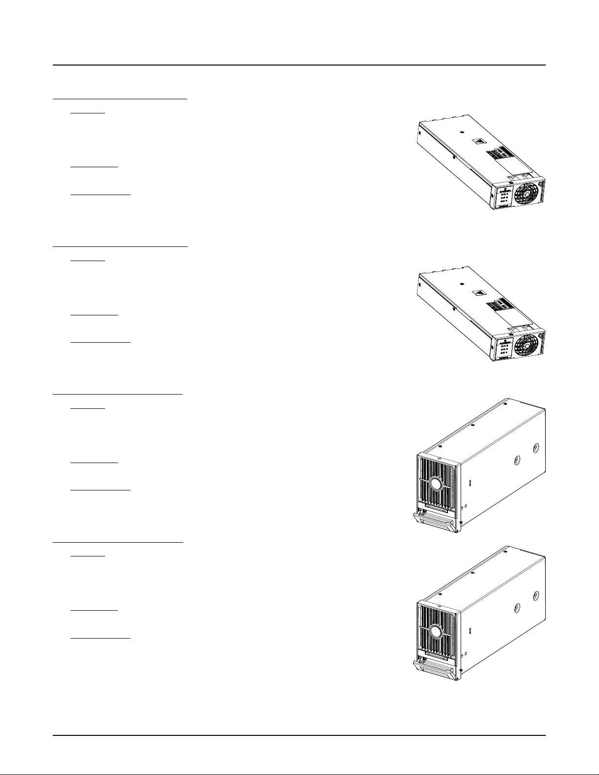
NetSure™ 7100 DC Power System
97
System Application Guide
Rectifiers
Rectifier Module, P/N 1R483500e3
Features
♦ Provides one (1) Model R48-3500e3, Spec. No. 1R483500e3,
3500 watt / -48 volt rectifier module.
♦ Refer to the Rectifier Instructions (UM1R483500e3) for more information.
Restrictions
For use in Spec. No. 588705400 module mounting assembly.
Ordering Notes
1) Order by P/N 1R483500e3 as required. Each Spec. No. 588705400 module mounting
assembly holds up to six (6) rectifier modules.
Rectifier Module, P/N 1R482000e3
Features
♦ Provides one (1) Model R48-2000e3, Spec. No. 1R482000e3,
2000 watt / -48 volt rectifier module.
♦ Refer to the Rectifier Instructions (UM1R482000e3) for more information.
Restrictions
For use in Spec. No. 588705300 module mounting assembly.
Ordering Notes
1) Order by P/N 1R482000e3 as required. Each Spec. No. 588705300 module
mounting assembly holds up to six (6) rectifier modules.
Rectifier Module, P/N 1R483500e
Features
♦ Provides one (1) Model R48-3500e, Spec. No. 1R483500e,
3500 watt / -48 volt rectifier module.
♦ Refer to the Rectifier Instructions (UM1R483500e) for more information.
Restrictions
For use in Spec. No. 588705000 module mounting assembly Lists 21, 22, 31, 32, 33.
Ordering Notes
1) Order by P/N 1R483500e as required. Each Spec. No. 588705000 module mounting
assembly holds up to six (6) rectifier modules.
Rectifier Module, P/N 1R484000e
Features
♦ Provides one (1) Model R48-4000e, Spec. No. 1R484000e,
4000 watt / -48 volt rectifier module.
♦ Refer to the Rectifier Instructions (UM1R483500e) for more information.
Restrictions
For use in Spec. No. 588705500 module mounting assembly Lists 01, 02, 03, 04, 05.
Ordering Notes
1) Order by P/N 1R484000e as required. Each Spec. No. 588705500 module mounting
assembly holds up to six (6) rectifier modules.
Spec. No: 582127000 SAG582127000
Model No: 7100 Revision BJ, August 21, 2020
Page 98
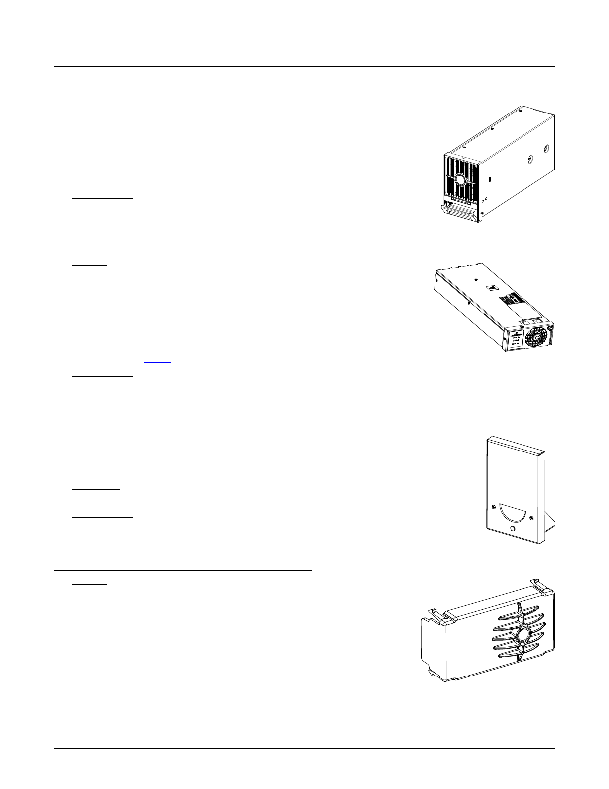
NetSure™ 7100 DC Power System
98
System Application Guide
Converters
DC-DC Converter Module, P/N 1C400483500e
Features
♦ Provides one (1) Model C400/48-3500e, Spec. No. 1C400483500e,
3500 watt / 400 V to -48 V DC-DC converter module.
♦ Refer to the Converter Instructions (UM1C400483500e) for more information.
Restrictions
For use in Spec. No. 588705000 module mounting assembly Lists 40, 41, 42.
Ordering Notes
1) Order by P/N 1C400483500e as required. Each Spec. No. 588705000 module mounting
assembly holds up to six (6) converter modules.
DC-DC Converter Module, P/N 1C48241500
Features
♦ Provides one (1) Model C48/24-1500, Spec. No. 1C48241500,
1500 watt / -48 V to +24 V converter module.
♦ Refer to the Converter Instructions (UM1C48241500) for more information.
Restrictions
For use in Spec. No. 588705300 module mounting assembly.
Converters can be installed in main bay only.
Must be used with List 60.
Ordering Notes
1) Order by P/N 1C48241500 as required. Each Spec. No. 588705300 module mounting assembly holds up to three (3)
converter modules (far right three mounting positions as viewed from the front).
Module Mounting Position Blank Cover Panels
Module Mounting Position Blank Cover Panel, P/N 21140440
Features
♦ Covers one (1) unused module mounting position.
Restrictions
For use in Spec. No. 588705000 and 588705500 module mounting assembly.
Ordering Notes
1) Order by P/N 21140440 as required. Order a module mounting position blank cover panel for each
empty module mounting position in the system, as desired.
Module Mounting Position Blank Cover Panel, P/N SXA1100035/1
Features
♦ Covers one (1) unused module mounting position.
Restrictions
For use in Spec. No. 588705300 and 588705400 module mounting assemblies.
Ordering Notes
1) Order by P/N SXA1100035/1 as required. Order a module mounting position blank
cover panel for each empty module mounting position in the system, as desired.
Spec. No: 582127000 SAG582127000
Model No: 7100 Revision BJ, August 21, 2020
Page 99

NetSure™ 7100 DC Power System
99
System Application Guide
Module Mounting Assembly
588705000 List 21:
Rectifier Module Mounting Assembly, 208 VAC / 240 VAC / 277 VAC Input, No AC Input Terminal Blocks (Factory Input
Wiring Only)
Features
♦ Provides one (1) Model PSS4850-23GV, Spec. No. 58870500021 module mounting assembly.
♦ This module mounting assembly holds up to six (6) rectifier modules.
♦ NO terminal blocks provided for AC input connections.
Restrictions
Module mounting assembly inputs MUST be factory wired into power system. For use with Lists 40, 41, 42 and 43 front
access AC input termination assemblies.
Ordering Notes
1) Order as required.
2) Order rectifier modules as required per P/N 1R483500e.
3) Order a module mounting position blank cover panel, P/N 21140440, for each empty module mounting position in the
system, as desired.
588705000 List 22:
Rectifier Module Mounting Assembly, 208 VAC, 240 VAC Input, Single-Phase, AC Input Line Cords
Features
♦ Provides one (1) Model PSS4850-23GV, Spec. No. 58870500022 module mounting assembly.
♦ This module mounting assembly holds up to six (6) rectifier modules.
♦ This module mounting assembly is equipped with individual rectifier module single-phase AC input feeds (one AC input
branch circuit per rectifier module, six AC input branch circuits per module mounting assembly).
♦ Factory wired AC input line cords equipped with NEMA L6-30P twist-lock plugs provided. (Six per shelf, each 7.5’ long,
12/3 AWG.)
Ordering Notes
1) Order as required.
2) Order rectifier modules as required per P/N 1R483500e.
3) Order a module mounting position blank cover panel, P/N 21140440, for each empty module mounting position in the
system, as desired.
588705000 List 31:
Rectifier Module Mounting Assembly, 208 VAC, 240 VAC, 277 VAC Input, Single-Phase, Rear Mount AC Input Terminal Blocks
Features
♦ Provides one (1) Model PSS4850-23GV, Spec. No. 58870500031 module mounting assembly.
♦ This module mounting assembly holds up to six (6) rectifier modules.
♦ This module mounting assembly is equipped with individual rectifier module single-phase AC input feeds (one AC input
branch circuit per rectifier module, six AC input branch circuits per module mounting assembly).
♦ Terminal blocks provided for AC input connections.
Restrictions
AC inputs MUST be wired directly to the shelf.
Ordering Notes
1) Order as required.
2) Order rectifier modules as required per P/N 1R483500e.
3) Order a module mounting position blank cover panel, P/N 21140440, for each empty module mounting position in the
system, as desired.
Spec. No: 582127000 SAG582127000
Model No: 7100 Revision BJ, August 21, 2020
Page 100

NetSure™ 7100 DC Power System
100
System Application Guide
588705000 List 32:
Rectifier Module Mounting Assembly, 208 VAC, 240 VAC Input, Three-Phase , Rear Mount AC Input Terminal Blocks
Features
♦ Provides one (1) Model PSS4850-23GV, Spec. No. 58870500032 module mounting assembly.
♦ This module mounting assembly holds up to six (6) rectifier modules.
♦ This module mounting assembly is equipped with two (2) three-phase AC input circuits. Each input circuit powers three
(3) single-phase rectifier modules, each connected from line to line, evenly distributed across the phases.
♦ Terminal blocks provided for AC input connections.
Restrictions
AC inputs MUST be wired directly to the shelf.
To maintain phase balance, rectifier modules should be installed in groups of three (all three on left and/or all three on right).
Ordering Notes
1) Order as required.
2) Order rectifier modules in groups of three per P/N 1R483500e.
3) Order a module mounting position blank cover panel, P/N 21140440, for each empty module mounting position in the
system, as desired.
588705000 List 33:
Rectifier Module Mounting Assembly, 277/480 VAC Input, Three-Phase, Rear Mount AC Input Terminal Blocks
Features
♦ Provides one (1) Model PSS4850-23GV, Spec. No. 58870500033 module mounting assembly.
♦ This module mounting assembly holds up to six (6) rectifier modules.
♦ This module mounting assembly is equipped with two (2) three-phase AC input circuits. Each input circuit powers three
(3) single-phase rectifier modules, each connected from line to neutral, evenly distributed across the phases.
♦ Terminal blocks provided for AC input connections.
Restrictions
AC inputs MUST be wired directly to the shelf.
To maintain phase balance, rectifier modules should be installed in groups of three (all three on left and/or all three on right).
Ordering Notes
1) Order as required.
2) Order rectifier module P/N 1R483500e only.
3) Order a module mounting position blank cover panel, P/N 21140440, for each empty module mounting position in the
system, as desired.
588705000 List 40:
Converter Module Mounting Assembly, 400V DC Input, No DC Input Terminal Blocks (Factory Input Wiring Only)
Features
♦ Provides one (1) Model PSS4850-23GV, Spec. No. 58870500040 module mounting assembly.
♦ This module mounting assembly holds up to six (6) converter modules.
♦ NO terminal blocks provided for DC input connections.
Restrictions
Module mounting assembly inputs MUST be factory wired into power system. For use with Lists 45, 46 and 47 front access
DC input termination assemblies.
Ordering Notes
1) Order as required.
2) Order converter modules as required per P/N 1C400483500e.
3) Order a module mounting position blank cover panel, P/N 21140440, for each empty module mounting position in the
system, as desired.
Spec. No: 582127000 SAG582127000
Model No: 7100 Revision BJ, August 21, 2020
 Loading...