


6Gb/s SAS
JBOD enclosure
Version:First Edition
Issue Date:Jan. 2011

SAFETY PRECAUTIONS
Please read this section carefully before proceeding. These precautions expl ain
the correct and safe use of this device, thereby helping t o prevent injury to you or
others, and also help you to minimize the risk of damaging the device.
Warnings
Always follow the basic warnings listed here to avoid the risk of serious injury or
death from electrical shock, short-circuiting, fire, and other hazards. These
warnings include, but are not limited to:
‧ With the exception of the user-swappable parts, do no attempt to
disassemble or modify the enclosure. If this device appears to be
malfunctioning, contact Netstor Customer Service.
‧ Do not drop the enclosures or any of its drive modules; dropping or
mishandling of the enc losure or drive modules may result in a malfunction.
‧ Do not insert your fingers or foreign objects inside the enclosure; take
particular care when small children are present.
‧ Do not expose the device to r ain, use it near water or containers that contain
liquids which might spill into any openings, or in damp or wet conditions.
‧ If unusual smell s, sounds, or smok e come from the device, or if liquids enter
it, switch it off immediately and unplug it from the electrical outlet.
‧ Follow the instructions in this manual carefully; contact Netstor Customer
Service for additional advice not covered in this User’s Guide.

Netstor | 1
Table of contents
1. Introduction…………………………………………………………………………… P2
1.1 Overview………………………………………………………………………………… P2
1.2 Package Checklist………………………………………………………………… P2
2. Hardware Installation………………………………………………………… P3
2.1 Panel Layout……………………………………………………………… P3
2.2 Enclosure Setup………………………………………………………… P8
3. LCD Configuration Manager…………………………………………………… P11
3.1 Using local front panel touch-control keypad…………….…… P12
3.2 Navigation Map of the LCD………………………………………………… P13
4. CLI Manager………………………………………………………………………………… P16
4.1 Expander RS-232C Port Pin Assignment…………………………… P17
4.2 Start-up VT100 Screen…………………………………………………… P17
4.3 CLI Command……………………………………………………………… P21
‧HELP Command………………………………………………………………… P21
‧PASS Command………………………………………………………………… P22
‧LO Command…………………………………………………………………… P22
‧
LINK Command………………………………………………………………… P23
‧GROUP Command…………………………………………………………… P25
‧SYS Command………………………………………………………………… P27
‧SPIN Command………………………………………………………………… P28
‧ST Command…………………………………………………………………… P29
‧LSD Command………………………………………………………………… P29
‧SHOWLOGS Command…………………………………………………… P31
‧FDL Command………………………………………………………………… P32
‧FAN Command………………………………………………………………… P34

2 | Netstor
Introduction
1. Introduction
1.1 Overview
Netstor’s enterprise-class 6Gb/s SAS Expander JBOD series is designed to provide storage
expansion for 6/3Gbps SAS RAID controller or 6/3Gbps SAS RAID adapter (SAS HBA). The
enclosure is equipped with 6Gbps SAS Expander supporting eight, twelve, and sixteen
high-reliable SAS 6/3Gbps or high-capacity SATA 6/3Gbps drives, with only one single
mini-SAS cable host connectivity, and provides two mini-SAS ports allowing you to expand
more 6Gb/s SAS JBOD enclosures, ensuring it the most cost-effective storage expansion.
1.2 Package Checklist
□ NS330S-8026
Before the installation of the enclosure, verify the items below are included in the package.
A. Enclosure × 1
B. HDD tray (installed in the NS330S-8026) × 16
C. CD containing user’s manual × 1
D. Hard disk drive mounting screw × 64
E. Key for HDD tray × 2
F. mini-SAS (SFF-8088) to mini-SAS (SFF-8088) data cable (optional) × 1
If any of the items listed above is missing or damaged, please contact the sales
representative.
□ NS320S-8026
Before the installation of the enclosure, verify the items below are included in the package.
A. Enclosure × 1
B. HDD tray (installed in the NS320S-8026) × 12
C. CD containing user’s manual × 1
D. Hard disk drive mounting screw × 48
E. Key for HDD tray × 2
F. mini-SAS (SFF-8088) to mini-SAS (SFF-8088) data cable (optional) × 1
If any of the items listed above is missing or damaged, please contact the sales
representative.

Netstor | 3
Hardware Installation
□ NS765S
Before the installation of the enclosure, verify the items below are included in the package.
A. Enclosure × 1
B. HDD tray (installed in the NS765S) × 8
C. CD containing user’s manual × 1
D. Hard disk drive mounting screw × 32
E. Key for HDD tray × 2
F. mini-SAS (SFF-8088) to mini-SAS (SFF-8088) data cable (optional) × 1
If any of the items listed above is missing or damaged, please contact the sales
representative.
2. Hardware Installation
This section gives the layout of the panel and describes the procedures for setting up the
6Gb/s SAS JBOD enclosure.
2.1 Panel Layout
□ NS330S-8026
1. LCD display
2. Enclosure power LED
。Green – Power On
3. Busy LED
。Flash green – Host computer accessing the enclosure
4. Fault LED
。Red – Enclosure failure
5. LCD control keypad
6. Drive presence LED
。White – Power On

4 | Netstor
Hardware Installation
7. Activity indicator LED
。Blue – Hard disk drive ready
。Flash Blue – Access
。Flash Pink – Rebuilding
。Red – Hard disk failure
8. Power switch button
9. Power supply alarm mute button
10. Power cord receptacle
11. SAS Exp. out connector
12. SAS Exp. in connector
13. SAS Exp. out connector
14. Activity LED
。Blue – When activity LED illuminates, it indicates SAS host accesses to NS330S-8026.
15. Link LED
。Green – When host port link LED illuminates for 1 second and light off for 3 seconds,
it indicates one link has connected.
When host port link LED illuminates for 2 seconds and light off for 2
seconds, it indicates two links have connected.
When host port link LED illuminates for 4 seconds, it indicates four links
have connected.
16. RS-232 port for CLI configuration
17. Fan 1
18. Fan 2
19. Fan 3
20. Fan 4
□ NS320S-8026
1. Drive presence LED
。White – Power On
2. Activity indicator LED

Netstor | 5
Hardware Installation
。Blue – Hard disk drive ready
。Flash Blue – Access
。Flash Pink – Rebuilding
。Red – Hard disk failure
3. Power switch button
4. Power supply alarm mute button
5. Power cord receptacle
6. Enclosure power LED
。Green – Power On
7. Busy LED
。Flash green – Host computer accessing the enclosure
8. Fault LED
。Red – Enclosure failure
9. LCD display
10. LCD control keypad
11. SAS Exp. out connector
12. SAS Exp. in connector
13. SAS Exp. out connector
14. Activity LED
。Blue – When activity LED illuminates, it indicates SAS host accesses to NS320S-8026.
15. Link LED
。Green – When host port link LED illuminates for 1 second and light off for 3 seconds,
it indicates one link has connected.
When host port link LED illuminates for 2 seconds and light off for 2
seconds, it indicates two links have connected.
When host port link LED illuminates for 4 seconds, it indicates four links
have connected.
16. RS-232 port for CLI configuration
17. Fan 1
18. Fan 2
19. Fan 3
20. Fan 4

6 | Netstor
Hardware Installation
□ NS765S
1. LCD display
2. System power LED
。Green – Power On
3. Busy LED
。Flash green – Host computer accessing the enclosure
4. Fault LED
。Red – Enclosure failure
5. LCD control keypad
6. Enclosure power LED
。White – Power On
7. Fan LED
。Green – Normal
。Red – Failure (low frequency of RPM or stop)
8. Temperature LED
。Green – Normal
。Red – Overheated (higher than 55℃)
9. Buzzer mute button
10. Drive presence LED
。White – Power On
11. Activity indicator LED
。Blue – Hard disk drive ready
。Flash Blue – Access
。Flash Pink – Rebuilding
。Red – Hard disk failure
12. SAS Exp. out connector
13. SAS Exp. in connector
14. SAS Exp. out connector
15. Link LED
。Green – When host port link LED illuminates for 1 second and light off for 3
seconds, it indicates one link has connected.

Netstor | 7
Hardware Installation
When host port link LED illuminates for 2 seconds and light off for 2
seconds, it indicates two links have connected.
When host port link LED illuminates for 4 seconds, it indicates four links
have connected.
16. Activity LED
。Blue – When activity LED illuminates, it indicates SAS host accesses to NS765S.
17. RS-232 port for CLI configuration
18. Swappable fan
19. Power cord receptacle
20. Power switch button
NOTE:
1. When one of the fans breaks down, the buzzer inside the 6Gb/s SAS JBOD enclosure
will beep.
For NS330S-8026 and NS320S-8026, to mute the beep, select “Set Alarm” from the LCD
display, and then enter the password “0000”. After you enter the password, select “Mute
Beep” and press enter to mute the beep. The other way to mute the beep is to click the
mute button from the GUI interface.
For NS765S, to mute the beep, press the mute button on the front panel.
2. For NS330S-8026 and NS320S-8026, when one of the two power supply units breaks
down, both buzzers of the power supply and enclosure will beep. To mute the beep from
the power supply, press the green alarm mute button on rear of the enclosure. And to
mute the beep from the enclosure, select “Set Alarm” from the LCD display, and then
enter the password “0000”. After you enter the password, select “Mute Beep” and press
enter to mute the beep. The other way to mute the beep from the enclosure is to click the
mute button from the GUI interface.

8 | Netstor
Enclosure Setup
2.2 Enclosure Setup
1. Remove the 6Gb/s SAS JBOD enclosure from its packaging, and place the enclosure next
to desktop PC, server, or workstation.
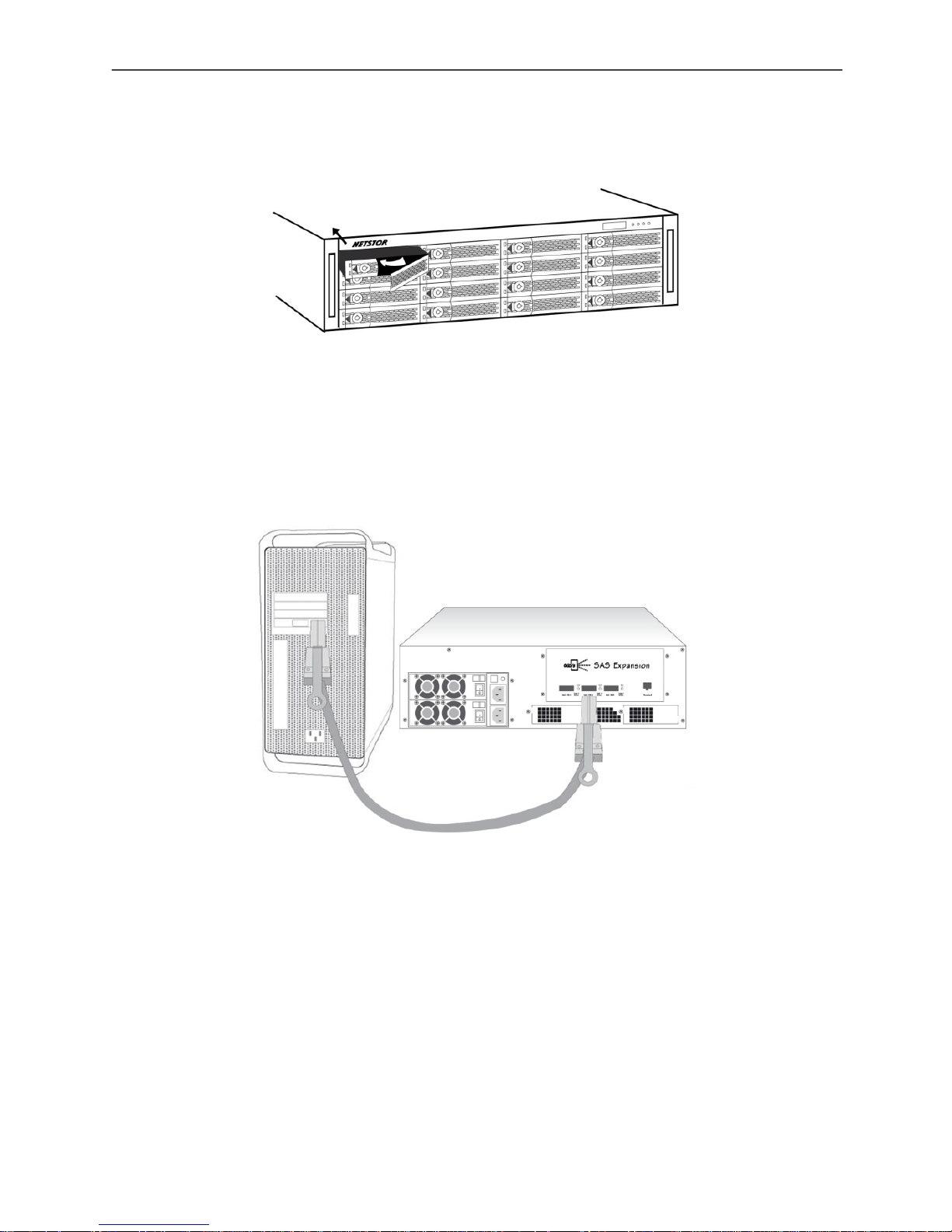
2. Hold one of the drive trays from the enclosure and push its button leftward for the release
of the lever until the lever pops out.
3. Place a drive tray on a flat and level surface, and then attach the hard disk drive into the
drive tray.
WARNING:
You must verify the heads of the four screws are level with the drive tray while the trays are
attached to the hard disk drives; otherwise, a screw could take hold of the tray from the
bottom side and prevent you to pull the drive tray out of the array.
4. Adopt four of the screws provided, and fasten the tray on the hard disk drive. Tighten
each screw to fasten the drive tray snugly to the hard disk drive. Do not tighten the
screws overly.
WARNING:
Do not force the levers to close while you insert drive modules into the 6Gb/s SAS JBOD
enclosure. If a lever does not close smoothly, draw out and insert the drive module again, and
then press the lever to close.
Netstor | 9
Enclosure Setup
5. Insert the drive module into the 6Gb/s SAS JBOD enclosure correctly until its lever
appears to shut, and then press the lever to close until it clicks to ensure that the drive
module is within the enclosure.
6. Repeat steps 2 to 5 for further drives.
7. Connect 6Gb/s SAS JBOD enclosure to the host interface: a host adapter or RAID
controller card through the SFF-8088 SAS cable. Connection between 6Gb/s SAS JBOD
enclosure and host adapter port is shown below:
8. Connecting 6Gb/s SAS JBOD enclosure’s RS-232 Port (optional)
。6Gb/s SAS JBOD enclosure’s system functions can be managed via a PC running a VT-100
terminal emulation program, or a VT-100 compatible terminal. The provided internal cable
converts the RS-232C signals from the RJ11 into the one 9-pin D-Sub male connector.
9. Add more 6Gb/s SAS JBOD enclosures (optional)
。6Gb/s SAS JBOD enclosure can be run in one of the two modes:
• Normal Mode
• Zone Mode
10 | Netstor
Enclosure Setup
You must select either mode using the CLI utility and re-start the 6Gb/s SAS JBOD enclosure.
The default is Normal Mode. Change the mode while 6Gb/s SAS JBOD enclosure is on. This
will not affect expander operation until 6Gb/s SAS JBOD enclosure is rebooted.
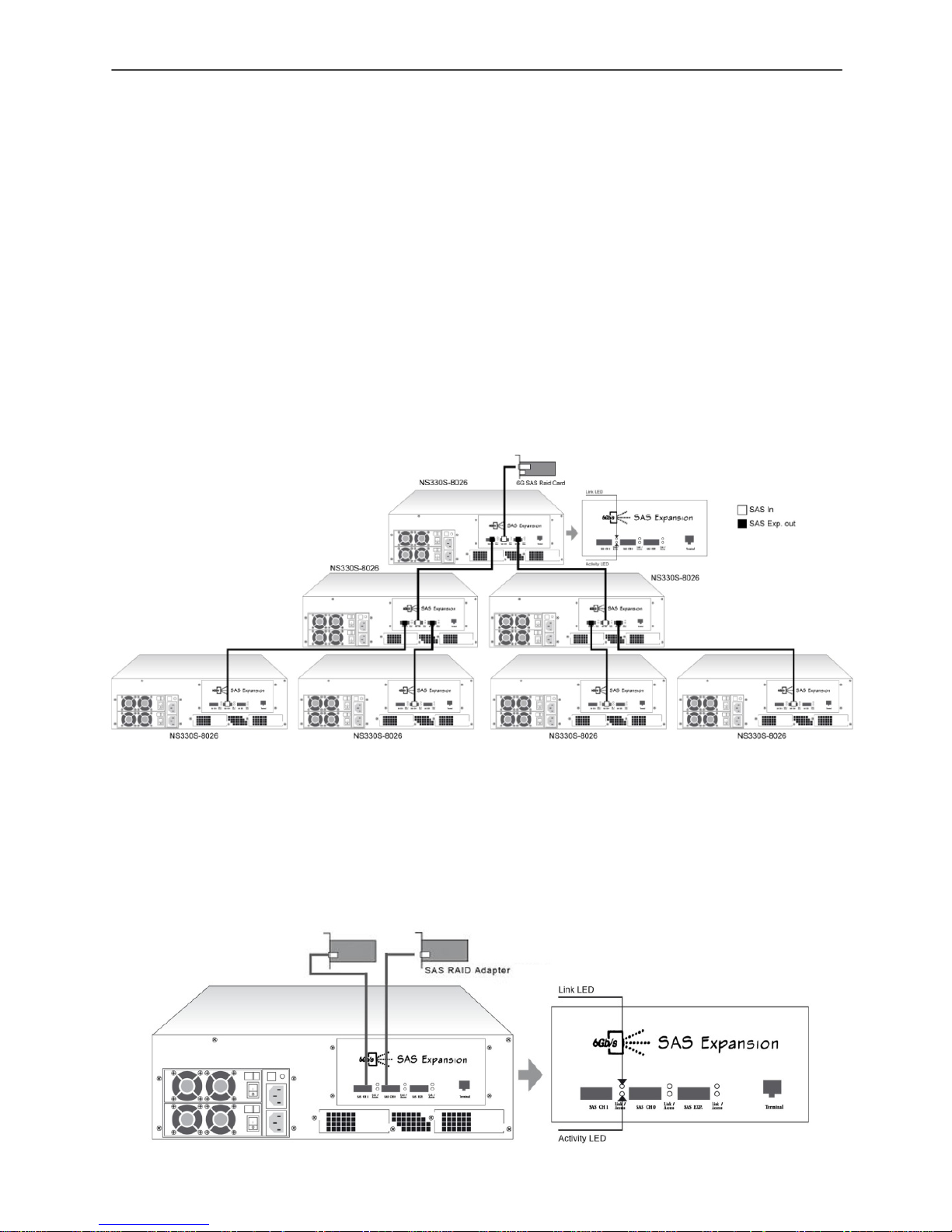
In normal mode, a SAS host can communicate with all drives in 6Gb/s SAS JBOD enclosure.
6Gb/s SAS JBOD enclosure contains expander ports. Expander ports can be attached to SAS
initiator ports, SAS and/or SATA target ports, and other expander ports. The SAS RAID
controller card or host adapter supports daisy-chain. The number of the 6Gb/s SAS JBOD
enclosures that can be supported depends on the RAID controller card or the host adapter
firmware. The following figure shows the connections of 6Gb/s SAS JBOD enclosures with
external mini-SAS data cables and SAS RAID controller card.
In zone mode, 6Gb/s SAS JBOD enclosure can be split into up to 8 virtual groups. Each
group’s drive channels and external cable connectors are assigned by CLI GROUP command.
The following figure shows 6Gb/s SAS JBOD enclosure that is split into 2 virtual groups. Each
group’s drive channels are controlled by individual host adapter using SAS CH1 and SAS CH2.

Netstor | 11
LCD Configuration Manager
Note:
1. Please refer to chapter 4.3 CLI features of GROUP command which is used to associate
the external port and the devices/phys slot.
2. The first thing is to turn on 6Gb/s SAS JBOD enclosure to make sure the SAS RAID
controller or SAS host adapter recognizes the drives in the enclosure.
10. As 6Gb/s SAS JBOD enclosure provides redundant power supply unit, connect one end
of the two power cords to the two receptacles on rear of 6Gb/s SAS JBOD enclosure,
and then connect the other end of the two power cords to the outlets.
11. After the two power cords are connected, you can switch on 6Gb/s SAS JBOD enclosure
and the computer.
3. LCD Configuration Manager
The 6Gb/s SAS JBOD enclosure LCD configuration utility is a character-based utility that you
can run after powering the unit. Use LCD configuration utility to see and configure:
• Alarm Device,
• Voltage,
• Set Link,
• Set Alarm,
• Set Password,
• Save Config, and
• System Reset
The LCD display front panel function keys are the primary user interface for 6Gb/s SAS JBOD
enclosure. Except for the "Firmware update", all configurations can also be performed
through this interface.

12 | Netstor
Using Local Front Panel Touch-Con t rol Keypad
3.1 Using Local Front Panel Touch-Control Keypad
The front panel keypad and liquid crystal display (LCD) is the primary user interface for 6Gb/s
SAS JBOD enclosure. All configuration and management of the expander controller and its
properly connected disk arrays can be performed from this interface. The front panel keypad
and LCD is to access the built-in configuration that resides in the 6Gb/s SAS JBOD
enclosure’s firmware.
The LCD provides a system of screens with areas for information, status indication, or menus.
The LCD screen displays up to two lines at a time of menu items or other information.
The initial screen is shown as following:
Function Key Definitions:
The four function keys at the right of the front panel perform the following functions:
Key Function
Up Arrow Use to scroll the cursor Upward / Rightward
Down Arrow Use to scroll the cursor Downward / Leftward
ENT Key Submit selected icon function (Confirm a selected item)
ESC Key Return to previous screen (Exit a selection configuration)
There are a variety of failure conditions that cause 6Gb/s SAS JBOD enclosure monitoring
LED to light. Below table provides a summary of the front panel LED.

Netstor | 13
Navigation Map of the LCD
Panel LED Normal Status Problem Indication
Power LED Bright green
This LED does not light up
after power switched on
Busy LED (Host
Access)
Blink green during host
computer accessing 6Gb/s
SAS JBOD enclosure
LED never flickers
Fault LED Unlit Solid red
3.2 Navigation Map of the LCD
The password option allows user to set or clear 6Gb/s SAS JBOD enclosure’s password
protection feature. Once the password has been set, the user can only monitor and configure
6Gb/s SAS JBOD enclosure by providing the correct password. The password is used to
protect 6Gb/s SAS JBOD enclosure from unauthorized entry. 6Gb/s SAS JBOD enclosure will
check the password only when entering the main menu from the initial screen. 6Gb/s SAS
JBOD enclosure will automatically go back to the initial screen when it does not receive any
command in 5 minutes. 6Gb/s SAS JBOD enclosure’s default password is 0000.
The following flow is an expansion of LCM setup option items hierarchical menu.

14 | Netstor
Navigation Map of the LCD
LCM setup option items hierarchical menu:

Netstor | 15
Navigation Map of the LCD
• Alarm Device
Show which device that fail to work, its sub-items could be "Power Supply", "Fan", "Temp.
Sensor" and "Voltage Sensor".
• Voltage
Show enclosure chip voltage in status data, represent in V.
The sub-items are shown as below:
1.2V- , 6Gb/s SAS JBOD enclosure voltage is 1.2V
5V- , 6Gb/s SAS JBOD enclosure voltage is 5V
For the setup item, the LCM keys represent:
Up key to enter the 0 - 9 data.
Down key to enter "a" - "z" and "A" - "Z" data.
Enter key to confirm the input or ready to update a sub-item data.
Esc / Exit key to go back to the main selection.
• Set Link
Set HDD devices maximun/minimun link speed rate. the value could be 6.0G, 3.0G or 1.5G
each of HDD devices link speed will have the sub-items are shown as below:
_Set Max. Rate
6.0G
_Set Min. Rate
1.5G
• Set Alarm
Set enclosure buzzer warning/critical error beep style or mute the current beep. The value
could be "Sound 1", "Sound 2", "Sound 3", "Sound 4" and "Sound Disabled". Sound 1 to 4
means different frequency sound. Sound disabled means disable the sound beep. The
sub-items are shown below:
_Set Alarm Beep
Mute beep
Warning Alarm
_Sound 2
_Critical Alarm
Sound 3

16 | Netstor
CLI Manager
• Set Password
Change the enclosure LCM/UART CLI password. The sub-item is "Set New PWD".
• Save Config
Save all the updated option value into non-volatile memory area.
• System Res e t
Reboot the system.
4. CLI Manager
This Command Line Interface (CLI) is provided for you to manage the 16 SAS expander
system functions. The CLI is useful in environments where a graphical user interface (GUI) is
not available.
• Locations of RS-232C Port
6Gb/s SAS JBOD enclosure uses the RJ11 port as the serial port interface. Please use the
cable included on the shipping box to configure the expander controller.
• Establishing the Connection for the RS-232 Port
The CLI function can be done by using an ANSI/VT-100 compatible terminal emulation
program. You must complete the appropriate installation procedure before proceeding with
the CLI function. Whichever terminal emulation program is used must support the 1K
XMODEM file transfer protocol.
The serial port on 6Gb/s SAS JBOD enclosure’s bracket can be used in VT100 mode. The
provided interface cable converts the RS232 signal of the RJ11 connector on the SAS
expander controller into a 9-pin D-Sub male connector. The firmware-based terminal SAS
expander management interface can access the expander through this RS-232 port. You
can attach a VT-100 compatible terminal or a PC running a VT-100 terminal emulation
program to the serial port for accessing the text-based setup menu.

Netstor | 17
Expander RS-232C Port Pin Assignment
4.1 Expander RS-232C Port Pin Assignment
To ensure proper communications between 6Gb/s SAS JBOD enclosure and the VT-100
Terminal Emulation, Please configure the VT100 terminal emulation settings to the values
shown below:
Terminal requirement
Connection Null-modem cable
Baud Rate 115,200
Data bits 8
Stop 1
Flow Control None
The controller RJ11 connector pin assignments are defined as below.
Action
Pin Description Pin
Description
1 RTS 3 TXD
2 RXD 4 GND
4.2 Start-up VT100 Screen
By connecting a VT100 compatible terminal, or a PC operating in an equivalent terminal
emulation mode, all CLI administration functions can be exercised from the VT100 terminal.
There are a wide variety of Terminal Emulation packages, but for the most part they should be
very similar. The following setup procedure is an example Setup VT100 Terminal in Windows
XP system using Hyper Terminal use Version 3.0 or higher.
18 | Netstor
Expander RS-232C Port Pin Assignment
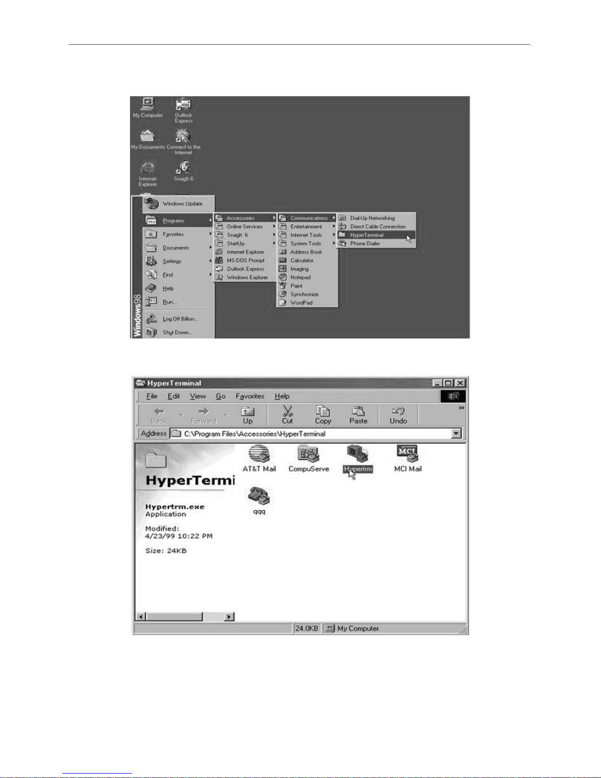
Step 1. Open the “Taskbar Start” / ”Programs" / "Accessories" / "Commmunications" /
"Heyper Terminal". (Heyper Terminal requires version 3.0 or higher).
Step 2. Open “HYPERTRM.EXE”.

Netstor | 19
Expander RS-232C Port Pin Assignment
Step 3. Enter a name you prefer and then click “OK”.
Step 4. Select an appropriate connecting port and then click "OK".
Step 5. Configure the port parameter settings and then click “OK”.
Bits per second: 115200
Data bits: 8
Parity: None
Stop bits: 1
Flow control: None

20 | Netstor
Expander RS-232C Port Pin Assignment
Step 6. Open the file menu and select “Properties”.
Step 7. Configure the "Connect To" setting.

Netstor | 21
CLI Command
Step 8. Configure the "Settings" items and then click "OK".
Function, arrow and ctrl keys act as: Terminal Keys
Backspace key sends: Crtl+H
Emulation: VT100
Telnet terminal: VT100
Back scroll buffer lines: 500
4.3 CLI Command
This section provides detailed information about 6Gb/s SAS JBOD enclosure’s CLI function.
All the commands please type in lower case.
• HELP Command
This command provides an on-line table of contents, providing brief descriptions of the help
sub-commands. You can use the <CLI> help to get detail information about the CLI commands
summary.
Syntax
CLI>help[Enter]
Example:
CLI>help
pass - Set Password
lo - Logout CLI Shell
link - Link Rate Control

22 | Netstor
CLI Command
group - Set the PHY Group
sys - System Information
spin - Drive SpinUp Control
st - Store System Setting
lsd - List Devices Status
showlogs - Show the Current Logs
fld - File Download
• PASS Command
The pass command allows user to set or clear 6Gb/s SAS JBOD enclosure password
protection feature. Once the password has been set, the user can only monitor and access
6Gb/s SAS JBOD enclosure setting by providing the correct password. The password can
accept max. 8 chars and min. 4 chars. The manufacture default password is “0000”.
Syntax
CLI>pass [Enter]
Example:
CLI>pass
Old Password:****
New Password:****
Verify New Password:****
Password Changed But Not Save Permanently!
Note, use CLI command “st” to keep permanently.
• LO Command
To exit the selected 6Gb/s SAS JBOD enclosure CLI shell, use the lo command.
Syntax
CLI> lo [Enter]
Example:
CLI>lo
Password:

Netstor | 23
CLI Command
• LlNK Command
The link command allows you to set the operational device link rate with the enclosure.
Typical parameters include: Max and Min disk speed with 6Gb/s SAS JBOD enclosure.
Syntax
CLI>link [Index Max Min] [Enter]
Index: Slot Index
Max, Min: speed code, 8 means 1.5G, 9 means 3.0G and
10 means 6.0G
PS. Pls. Save Config. & Reboot To Take Effect
CLI>st
Example:
CLI>link
ArrayDevice Element (0x17):
========================================================================
NAME PHY NLR MAX MIN TYPE ADDRESS
SLOT 01 0 3.0G 10 8 SAS 5000C500-0D2002D1
SLOT 02 1
10 8
SLOT 03 2
10 8
SLOT 04 3 1.5G 10 8 SATA 5001B469-84965C03
SLOT 05 4
10 8
SLOT 06 5
10 8
SLOT 07 6 6.0G 10 8 SAS 5000C500-17C8FD25
SLOT 08 7
10 8
SLOT 09 8
10 8
SLOT 10 9
10 8
SLOT 11 10
10 8
SLOT 12 11
10 8
//Set the slot 0x6 max. speed to 1.5G
CLI >link 6 9 8
CLI >link

24 | Netstor
CLI Command
ArrayDevice Element (0x17):
========================================================================
NAME PHY NLR MAX MIN TYPE ADDRESS
SLOT 01 0 3.0G 10 8 SAS 5000C500-0D2002D1
SLOT 02 1
10 8
SLOT 03 2
10 8
SLOT 04 3 1.5G 10
8 SATA 5001B469-84965C03
SLOT 05 4
10 8
SLOT 06 5
10 8
SLOT 07 6 6.0G 90 8 SAS 5000C500-17C8FD25
SLOT 08 7
10 8
SLOT 09 8
10 8
SLOT 10 9
10 8
SLOT 11 10
10 8
SLOT 12 11
10 8
CLI>st
CLI>
Reboot to take effect.
CLI >link
ArrayDevice Element (0x17):
========================================================================
NAME PHY NLR MAX MIN TYPE ADDRESS
SLOT 01 0 3.0G 10 8 SAS 5000C500-0D2002D1
SLOT 02 1
10 8
SLOT 03 2
10 8
SLOT 04 3 1.5G 10 8 SATA 5001B469-84965C03
SLOT 05 4
10 8
SLOT 06 5
10 8
SLOT 07 6 3.0G 9
8 SAS 5000C500-17C8FD25
SLOT 08 7
10 8
SLOT 09 8
10 8

Netstor | 25
CLI Command
SLOT 10 9
10 8
SLOT 11 10
10 8
SLOT 12 11
10 8
• GROUP Command
The group command is used to associate the external port with the devices/phys as one zone
group. The three external cable ports and all devices/phys slots will default associate with
one zone group.
Syntax
gr {dev GroupNo[1..] {ci, cj, ck,..} Start-Index(D) End-Index(D)}
gr {off | [t10 off] }
dev : use drive slot index
GroupNo : groupno start from 1, max 8 groups ci, cj, ck,..: external cable connector. i, j, k,..
is the index which range from 0 to 3. According to view from connector side, index start
from right to left or top to bottom. The cable c0, c1, or c2 is view from right to left or start
from top to bottom.
Start-Index : Start slot index of zone range, [1.. max drive]
End-Index : End slot index of zone range, [1.. max drive]
off : clear the zone group setting.
t10 off : turn T10 mode off.
Example:
CLI>gr
Current PHY Group Mode: T10
Group-1: C0, C1, C2, Slot: 1, 2, 3, 4, 5, 6, 7, 8, 9, 10, 11, 12,
13, 14, 15, 16
Value: 0x0000000FFFFFFFFF
//Set the cable0 and slot 1 to slot 6 as group 1
CLI>gr dev 1 c0 1 6
New PHY Group Mode: T10
Group-1: C0, Slot: 1, 2, 3, 4, 5, 6
Value: 0x00000000000FFC00

26 | Netstor
CLI Command
Current PHY Group Mode: T10
Group-1: C0, C1, C2 Slot: 1, 2, 3, 4, 5, 6, 7, 8, 9, 10, 11, 12, 13,
14, 15, 16
Value: 0x0000000FFFFFFFFF
//Set the cable1 and cable2 and slot 7 to slot 16 as group 2
CLI>gr dev 2 c1, c2 7 16
New PHY Group Mode: T10
Group-1: C0, Slot: 1, 2, 3, 4, 5, 6
Value: 0x00000000000FFC00
Group-2: C1, C2, Slot: 7, 8, 9, 10, 11, 12, 13, 14, 15, 16
Value: 0x000000000FF003FF
Current PHY Group Mode: T10
Group-1: C0, C1, C2 Slot: 1, 2, 3, 4, 5, 6, 7, 8, 9, 10, 11, 12, 13,
14, 15, 16
Value: 0x0000000FFFFFFFFF
CLI>st
Power Cycle to reboot
CLI>gr
Current PHY Group Mode: T10
Group-1: C0, Slot: 1, 2, 3, 4, 5, 6
Value: 0x00000000000FFC00
Group-2: C1, C2, Slot: 7, 8, 9, 10, 11, 12, 13, 14, 15, 16
Value: 0x000000000FF003FF
//Clear the Zone group Setting
CLI>gr off

Netstor | 27
CLI Command
New PHY Group Mode: T10
Group-1: C0, C1, C2 Slot: 1, 2, 3, 4, 5, 6, 7, 8, 9, 10, 11, 12, 13,
14, 15, 16
Value: 0x0000000FFFFFFFFF
Current PHY Group Mode: T10
Group-1: C0, Slot: 1, 2, 3, 4, 5, 6
Value: 0x00000000000FFC00
Group-2: C1, C2, Slot: 7, 8, 9, 10, 11, 12, 13, 14, 15, 16
Value: 0x000000000FF003FF
• SYS Command
The sys command is used to view the information of 6Gb/s SAS JBOD enclosure.
Typical information includes: vendor, model name, serial/unit number, expander port number,
product revision, chip name/chip revision, customer code, manufacture data revision and
work time.
Syntax
CLI>sys [Enter]
Example:
CLI>sys
========================================
========================================
Hardware Revision Information:-
========================================
========================================
Vendor ID : Netstor Technology Co Ltd. Taiwan, R.O.C.
Model ID : NS330S
Serial No. : 0000000000000000
Unit Serial No. :
Expander SAS Address : 0x5001B46984965C3F
Product Revision : 0

28 | Netstor
CLI Command
Exapnder Chip ID : 0x0221 (Ports : 28)
Exapnder Chip Revision : B3
Customer Code : 0x36
Manufacturer Data Revision : 0xB2
Wroking Time : Day00000-01:48:14
========================================
========================================
Firmware Revision Information:-
========================================
========================================
Active Firmware: Active Image
Boot Image:
Revision: 6.01.00.68 06/30/10
Firmware Family: 1 Fast Boot: No Image Address: 0x14000000
Active Image:
Revision: 6.01.00.68 06/30/10
Firmware Family: 1 Fast Boot: No Image Address: 0x14080000
Backup Image:
Revision: 6.01.00.68 06/30/10
Firmware Family: 1 Fast Boot: No Image Address: 0x14100000
• SPIN Command
The spin command defines the mode of staggering SATA drive spin-up function connected to
6Gb/s SAS JBOD enclosure. This command gives 6Gb/s SAS JBOD enclosure the ability to
spin up the disk drives sequentially or in groups, allowing the drives to come ready at the
optimum time without straining the system power supply. Staggering drive spin-up in a
multiple drive environment also avoids the extra cost of a power supply designed to meet
short-term startup power demand as well as:
Syntax
CLI> spin [ Delay(D)[ms] Num(D) ]
Expander issues the spin up the drives by [ Num] drives with

Netstor | 29
CLI Command
[Delay] ms.
Example1:
CLI>spin
Current SpinUp Attribute:
Drive Number: 1
Delay: 1024 ms
CLI>spin 512 3
New SpinUp Attribute:
Drive Number: 3
Delay: 512 ms
Current SpinUp Attribute:
Drive Number: 1
Delay: 1024 ms
• ST Command
The st command stores system configurations in flash. Since all the revised parameter setting
is temporarily stored in the working RAM, the ST command saves those parameters
permanently in flash ROM.
Syntax
CLI> st
Example:
CLI> st
CLI>
• LSD Command
The lsd command is use for show the element devices status in the expander controller. With
parameter, this command only shows the seletct device status.
Syntax
CLI> lsd [ hdd | temp | volt | pwr | con | ..]
Show SES elements information:

30 | Netstor
CLI Command
ArrayDevice Element (0x17):
========================================================================
NAME PHY NLR MAX MIN TYPE ADDRESS
SLOT 01 0 3.0G 10 8 SAS 5000C500-0D2002D1
SLOT 02 1
10 8
SLOT 03 2
10 8
SLOT 04 3 1.5G 10 8 SATA 5001B469-84965C03
SLOT 05 4
10 8
SLOT 06 5
10 8
SLOT 07 6 6.0G 10 8 SAS 5000C500-17C8FD25
SLOT 08 7
10 8
SLOT 09 8
10 8
SLOT 10 9
10 8
SLOT 11 10
10 8
SLOT 12 11
10 8
Connector Element (0x19):
========================================================================
NAME PHY NLR TYPE STATUS
Connector00 16
02
Connector00 17
02
Connector00 18
02
Connector00 19
02
Connector01 20 6.0G 02 Connected
Connector01 21 6.0G 02 Connected
Connector01 22 6.0G 02 Connected
Connector01 23 6.0G 02 Connected
Connector02 24
02
Connector02 25
02
Connector02 26
02
Connector02 27
02
Cooling Element (0x03):

Netstor | 31
CLI Command
========================================================================
NAME SPEED CODE RPM STATUS
Fan 01 5 2100 OK
Fan 02 5 2200 OK
Fan 03 Not-Installed
Fan 04 Not-Installed
Temperature Element (0x04):
========================================================================
NAME ID CT(‘C) HTW LTW OTWarn
ENC. Temp 01 32 60 5 No
Chip Temp 02 42 85 5 No
Voltage Element (0x12):
========================================================================
NAME VOLT(V) OVLMT UVLMT STATUS
1V 0.99 1.07 0.94 None
5V 4.96 5.32 4.63 None
PowerSupply Element (0x02):
========================================================================
NAME STATUS
PowerSupply01 OK
PowerSupply02 OK
AudibleAlarm Element (0x06):
========================================================================
NAME STATUS ALMSTATE
Audible-Alarm Normal 0
CLI>
• SHOWLOGS Co mmand
The showlogs command allows you to display system event notifications that have been
generated by 6Gb/s SAS JBOD enclosure.
Syntax
CLI>showlogs [DisplayMode(hex, detail, default)]
Example:

32 | Netstor
CLI Command
CLI>showlogs
00000000-00000000:PLATFORM:Firmware initialization started
Day00000-00:00:00 ENCLOSURE-Fan 01 Failed
• FDL Command
6Gb/s SAS JBOD enclosure has added the expander firmware update through the CLI on the
external RS-232 port. Before you process the firmware update, there are two block regions
that you can update expander microcode on 6Gb/s SAS JBOD enclosure.
(1)CODE region - for FW file : sas2xfwXXXX.fw
(2)MFGB region - for Data file : mfgdat6gYYYY.rom
To update the expander controller firmware, follow the procedure below:
Syntax: all the commands please type in lower case
CLI>fdl { code | mfgb } offset[Enter]
Then use XModem/(Checksum) protocol transmit file to update ROM Region
The following procedures are used to update firmware through the RS-232:
A. Open any UART communication tools like HypeTerminal(115200,n,8,1).
B. Press any key on HyperTerminal window, the window will show “CLI>” prompt.
C. Type help will show help screen.
D. One command to update firmware. Step as follow,
E. Issue download & update command under “CLI>”.
CLI>fdl code 0
Please Use XModem Protocol for File Transmission.
Use Q Or q to quit Download before starting XModem.
<-----expander prompt for ready to receive file to update.
F. Then under HyperTerminal program, use the pull down menu item transfer “Send” ->
send files when dialog box prompts, choose “Xmodem” and the file in the directory then
press “send”.
(1). If the expander receives the file under the timeout limit (60s), the process starts.
(2). If time out, please retry the step E again.

Netstor | 33
CLI Command
G. You can also cancel the program step by type ‘q’.
H. If transfer OK, the transfered data is updated. Cold-start expander (Power cycle again) to
take effect.
Example:
Update procedure, use Xmodem to transfer, refer to “fdl” command for detail operation.
CLI> fdl { code | mfgb } offset[Enter]
Use HyperTerminal or TeraTerm utility with Xmodem mode to transfer and update files.
If transfer OK, the transfered data is updated. Cold-start expander (Power cycle again) to
take effect.
The following firmware and data are available in the following filename format.
(1)FW file (CODE) : sas2xfwXXXX.fw
(2)Data file (MFGB) : mfgdat6gYYYY.rom
Update 6Gb/s SAS JBOD enclosure firmware:
CLI> fdl code 0
Use HyperTerminal or TeraTerm utility with Xmodem mode to transfer sas2xfwXXXX.fw.
If transfer OK, the transfered data is updated. Cold-start expander (Power cycle again) to
take effect.
Update SAS expander data file:
CLI>fdl mfgb 0
Use HyperTerminal or TeraTerm utility with Xmodem mode to transfer mfgdat6gYYYY.rom.
If transfer OK, the transfered data is updated. Cold-start expander (Power cycle again) to
take effect.

34 | Netstor
CLI Command
• FAN Command
The fan command defines the speed of the four fans within the 6Gb/s SAS JBOD enclosure.
You are able to set the speed of fan on code between 1 and 7. Code 1 means the slowest
speed, and code 7 stands for the highest speed of fan. It is suggested that the speed of fan to
be set between codes 5 to 7 because as it is set under code 4, the system for the detection of
fan speed becomes sensitive and it will get to beep easily.
Syntax
CLI> fan [ speed code | speed code ] [Enter]
The speed of the four fans will be defined by the speed code you entered.
Example:
CLI> fan 7 7
The speed of the four fans will be set to the highest.
CLI> st
Save the configuration to the system.
Contacting Netstor Customer Service
The Netstor website at www.netstor.com.tw has technical updates, and the most
current product and support information. Please check our website for the lat es t
updates and online support files for helpful information. If further assistance is
needed, please contact us in one of the following ways:
Skype: netstor_fae
E-mail: fae@netstor.com.tw
Tel: +886-2-2917-1500
 Loading...