


NA255A
Performance Desktop PCIe 3.0 x16 (128Gbps) upstream port PCI-Express
expansion enclosure particularly design for GPU cards
(Available up to 4* double width PCIe Gen3 slots)
User Manual
First edition, Dec. 2017

1. Unpack the NA255A
3
2. Expansion Chassis Description
2.1 Panel Layout
2.2 Slot Board Layout
2.3 Switches Function and Location on
NA255A Slot Board
2.4 LED Status on Host card and Target card
3. Install Graphics/PCIe Cards in NA255A
3.1 Procedure for Card Installation
3.2 Cooling Fan Speed Adjustment
3
3
5
6
7
8
8
12
4. Powering On/Off NA255A
5. Verification
5.1 Windows Operating System
5.2 macOS / tower Mac Pro
13
14
14
16

1. Unpack the NA255A
The box contains the following items:
。Netstor NA255A
。PCIe 3.0 ×16 host card
。Two PCIe 3.0 ×8 1.5-meter cables
。Power cord
2. Expansion Chassis Description
2.1 Panel Layout
4. Temperature LED
。Green – normal
。Red – over temperature (above 55℃)
3. Fan LED
。Green – normal
。Red – fan failure
(low frequency of RPM or stop)
2. Buzzer mute button
1. Power on/off LED button
。Blue - power on
Note: when at powering on/off NA255A manually mode, to power
on/off NA255A, hold the power LED button for two seconds
until the LED button shows blue light or off.
3
Go Top ↑

10. Thumbscrews to loosen/
tighten the side door
9. PCIe slots
8. Two external PCIe 3.0 ×8 connectors for host connection
。One port is marked with ×8 for lane 1~8; the other port is marked
with ×16 for lane 9~16. Make straight cable connection between
target card in NA255A and host card in computer with mark ×8
to ×8, and ×16 to ×16. Do NOT make cross cable connection.
X16
X8X16
X8
X8X16
7. Link status LED
。PCIe Gen3 : solid green light
。PCIe Gen2 : fast blinking green light
(2 flashes/second)
。PCIe Gen1 : slow blinking green light
(1 flash/second)
6. Power receptacle
5. PSU power switch
X16
X8
4
Go Top ↑

2.2 Slot Board Layout
5. Slot 5 : PCIe ×16 connector (×8 signal)
4. Slot 4 : PCIe ×16 connector (×8 signal)
3. Slot 3 : PCIe ×16 connector (×8 signal)
2. Slot 2 : PCIe ×16 connector (×8 signal)
1. Slot 1 : PCIe ×16 connector (×16 signal)
Target card already installed in it
6. 4×6+2 pin PCIe power cables & 4×6-pin PCIe power cables for cards
5
Go Top ↑

2.3 Switches Function and Location on NA255A Slot Board
SW2-1
Go Back to 4.
。To set NA255A power on/off by host computer, turn SW2-1 switch to ON position. (default)
。To set NA255A power on/off manually, turn SW2-1 switch to OFF position.
※ SW2-1 and SW2-2 switches are near slot 5 on backplane.
FAN SPEED LOW
FAN SPEED HIGH
SW2-2
。To set 3.5 x 3.5 cm cooling fan speed on backplane to high,
turn SW2-2 switch to ON position.
。To set 3.5 x 3.5 cm cooling fan speed on backplane to low,
turn SW2-2 switch to OFF position. (default)
3.5 x 3.5 cm
Gen3
Gen2
NP952AG3 Rev.A0
SW1
Go Back to 3.
。To set NA255A as Gen3 mode, turn switch to left position. (default)
。To set NA255A power on/off manually, turn SW2-1 switch to OFF position.
6
Go Top ↑

2.4 LED Status on Host card and Target card
。LED2 ~ LED6 show solid green light: PCIe x16 connection between computer and NA255A is linked
。LED3 ~ LED6 show solid green light: PCIe x8 connection between computer and NA255A is linked
。LED2 ~ LED6 no light: PCIe connection between computer and NA255A is NOT linked
136 mm
87 mm
7
Go Top ↑

3. Install Graphics/PCIe Cards in NA255A
Before card installation in NA255A, read through the following notice and instructions.
The computer’s PCIe slot to be linked with NA255A must be identified first for the correct
connection between host computer and NA255A.
Two conditions A and B for connection are listed below:
A. If computer’s PCIe slot to be linked with NA255A is PCIe 3.0 ×16 or PCIe 3.0 x8, you don’t
need to make any change to the switch setting on NA255A slot board because NA255A is
already set to work with computer’s PCIe 3.0 x16/x8 slot by default.
B. If computer’s PCIe slot to be linked with NA255A is PCIe 2.0 ×16 or PCIe 2.0 x8, you will
need to set NA255A’s slot board to PCIe Gen2 to have Netstor unit be compatible with
tower Mac Pro or host computer. The approach to set NA255A slot board to PCIe 2.0 is
given in section 2.3 (SW1) in this user’s manual.
3.1 Procedure for Card Installation
Prior to card installation, make sure NA255A is disconnected from power source to prevent
electric shock or damage to graphics/PCIe card.
1. Install Netstor NP970AG3-H host card into the PCIe slot on motherboard within computer.
2. Loosen the two thumbscrews and remove the side door from NA255A.
8
Go Top ↑

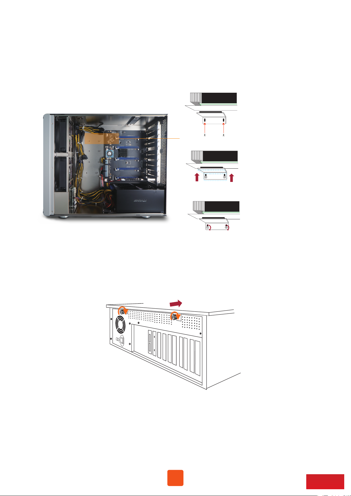
3. Remove the L shape metal bracket at rear of NA255A by loosening the screw on metal bracket.
4. Install one graphics/PCIe card into the PCIe ×16 slot in NA255A and tighten the card with screw.
5. Each graphics card in NA255A is provided with supplementary 6+2 pin and 6-pin PCIe power
cables for sufficient power. Up to four dual-width, full-length graphics cards can be installed
in slots 2 ~ 5 in the Netstor chassis.
9
Go Top ↑
NOTICE
When long length and heavy weight graphics card is to be installed in NA255A, it’s strongly
recommended the graphics card holder is also installed to add stability to GPU card within
the chassis. The procedure for card holder installation is given as follows:
Graphics card
Graphics card
Graphics card
(A) Hold the included graphics card holder. Aim
holder’s two holes at the two screw openings
at top of the two pillars within NA255A
enclosure, and have two screws loosely
tightened to card holder.
(B) Slowly push up the bottom side of the metal
card holder until the top side of holder is
firmly attached to graphics card’s metal
back plate.
(C) At this time, use a screwdriver to tightly
tighten the two screws to have graphics
card holder securely fastened to the inside
of NA255A enclosure.
6. Put the side door back to NA255A, and tighten the two thumbscrews to fasten
the side door with enclosure.
10
Go Top ↑

7. Connect one end of two data cables to PCIe connectors at rear of NA255A, and connect
the other end of two data cables to PCIe connectors on NP970AG3-H host card in computer.
X16
X8
X8X16
Host - Red LED
X16
X8
Note: Make straight cable connection between target card
in NA255A and host card in computer with mark ×8 to ×8,
and ×16 to ×16. Do NOT make cross cable connection.
NP970AG3-H Host card
8. Connect one end of power cord to NA255A’s power receptacle and the other end of power
cord to grounded outlet or power strip.
11
Go Top ↑
3.2 Cooling Fan Speed Adjustment
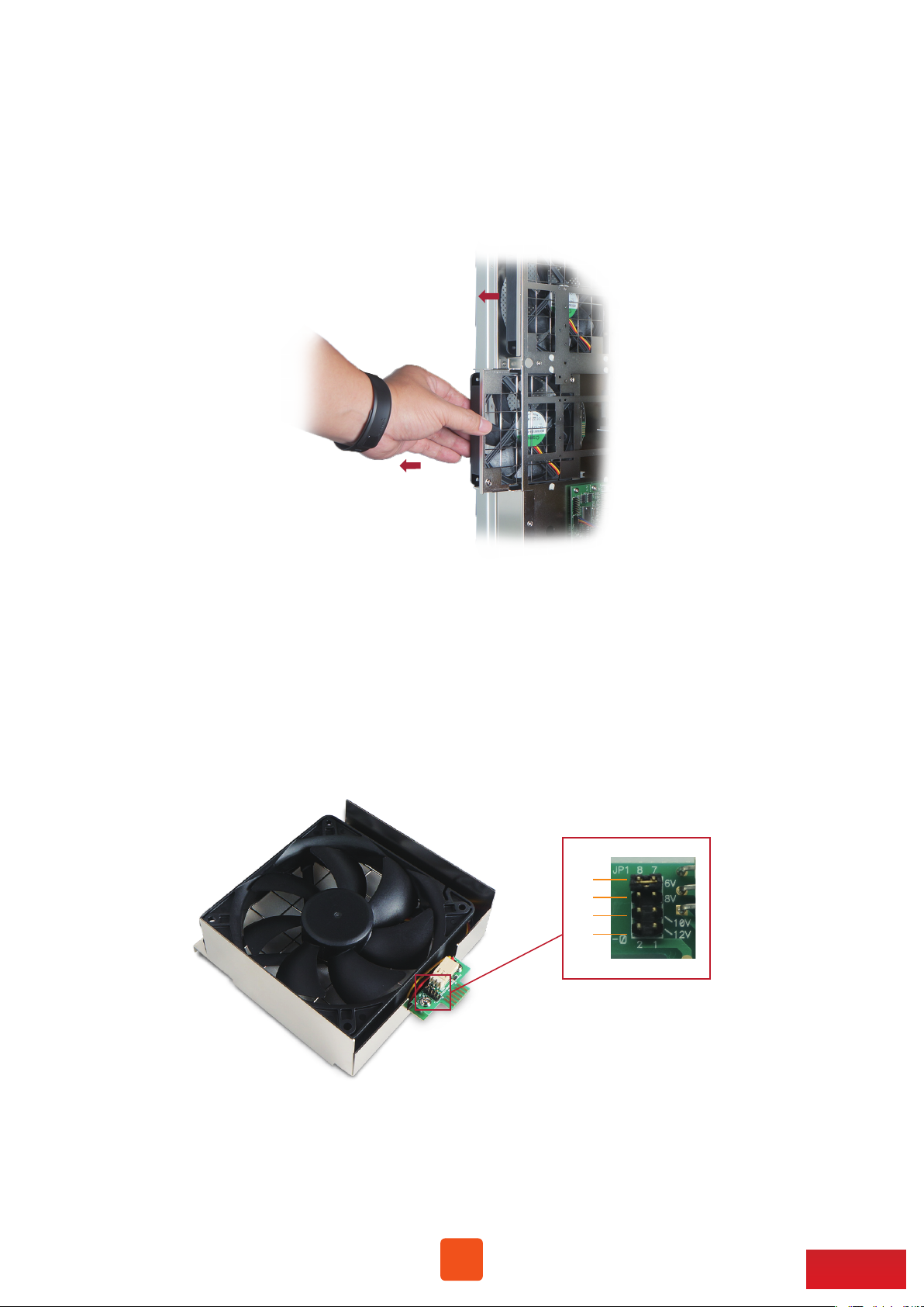
1. There are two hot-swappable 120×120×25 mm cooling fans for ventilation inside
NA255A. The cooling fans can be drawn out by pulling the L type metal handle on
the fan modules.
2. The front 120×120×25 mm cooling fan speed can be adjusted. Pull out the fan module,
there are four sets of jumpers labeled with 6V, 8V, 10V, 12V from top to bottom on the
fan connector board. The default setting is the jumper being placed over pin 7 and 8 for
label 6V for slowest speed. The speed increases from label 8V to label 12V. As jumper is
not placed over pins, the fan will spin at 12V full speed.
6V
8V
10V
12V
12
Go Top ↑
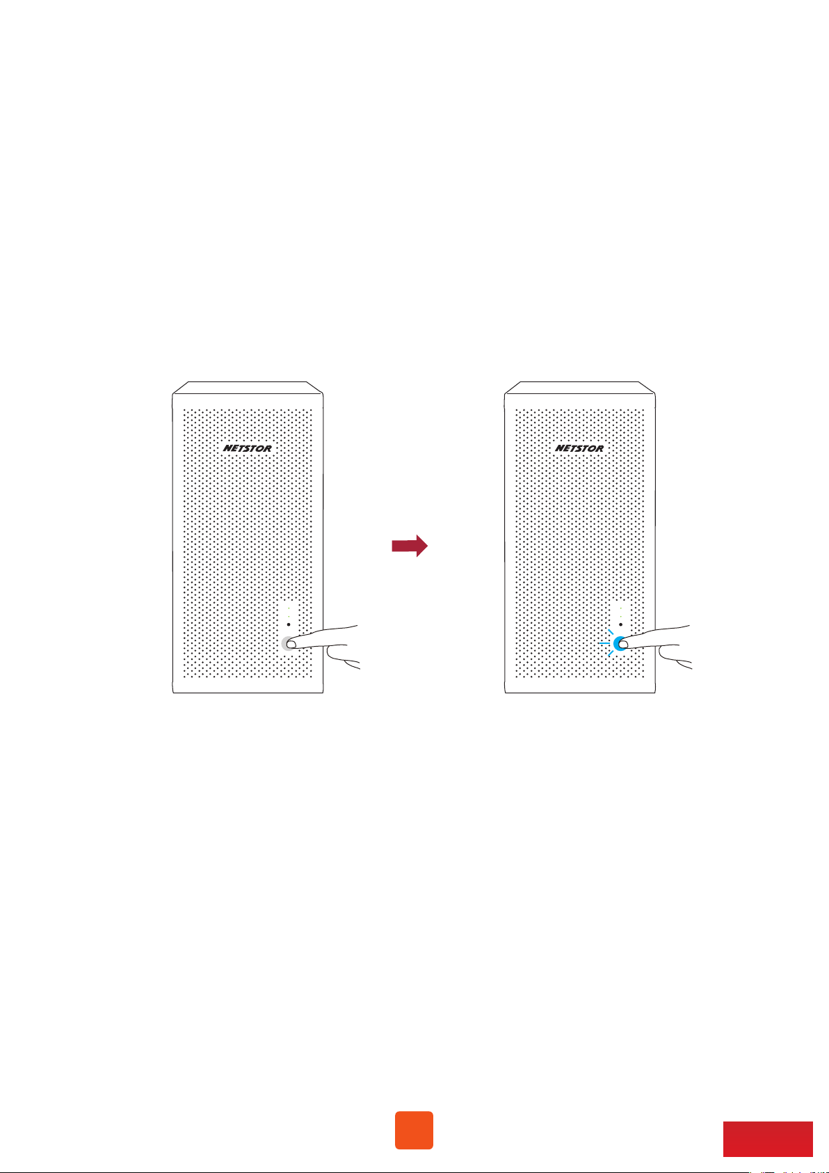
4. Powering On/Off NA255A
When NA255A is set for powering on/off by host, the NA255A will be automatically powered
on and off with the host computer. (Default)
If NA255A is set for powering on/off manually, the standard powering on/off procedure
below must be followed (go to Section 2.3, SW2-1):
1. Power on NA255A by holding the power LED button for two seconds until the
LED button shows blue light.
2. In order to let computer’s BIOS identify and assign PCIe resources appropriately,
always power on NA255A first, and then power on computer.
3. To remove NA255A from computer, always power off computer first, and then
power off NA255A.
13
Go Top ↑

5. Verification
5.1 Windows Operating System
1. Go to Windows’ Device Manager. Click View at the top menu bar, and select
Devices by connection.
2. Open ACPI x64-based PC >> Microsoft ACPI-Compliant System >> PCI Express Root Complex.
Then open PCI Express Root Port >> PCI standard PCI-to-PCI bridge.
The graphics/PCIe cards in NA255A will appear under the PCI standard PCI-to-PCI bridge.
3. There will be PCI Express Root Ports with different ending numbers like 1C10, 1C18, and
1C1A. These different ending numbers indicate the different PCIe slots on computer
motherboard.
14
Go Top ↑

4. No software or driver is required for NA255A itself. As a graphics/PCIe card is in NA255A,
the request for the driver of the graphics/PCIe card will be prompted at operating system.
Please follow the driver installation instructions given by the manufacturer of the
graphics/PCIe card.
5. As the driver is installed on operating system, the graphics/PCIe card in NA255A will
work properly with computer, and the graphics/PCIe card within the Netstor unit will
be shown correctly in Device Manager.
6. Whether a computer motherboard supports four graphics cards depends on the BIOS
of motherboard. Consult with the manufacturer of motherboard to see if BIOS’s
resource supports four graphics cards.
15
Go Top ↑
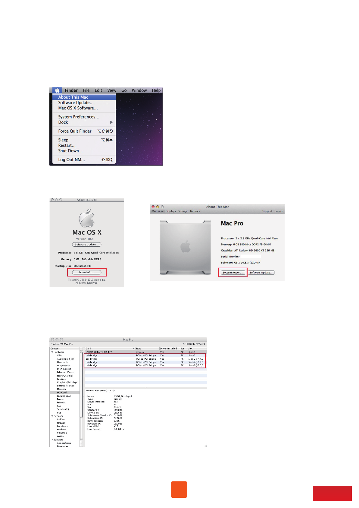
5.2 macOS / tower Mac Pro
1. To check card verification on macOS at tower Mac Pro, click Apple icon at the
top menu bar, and select About This Mac.
2. As pane of About This Mac pops up, click System Report.
3. Click PCI in the left column. It will show four pci-bridges that indicate the
four PCIe slots in NA255A in the information field.
16
Go Top ↑
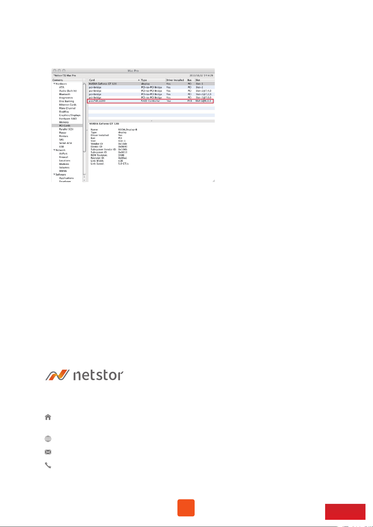
4. As graphics/PCIe cards are installed in NA255A, the graphics/PCIe cards will
appear below the four pci-bridges.
5. After graphics/PCIe cards’ drivers are installed on macOS, the graphics/PCIe cards
in NA255A will be ready to work with tower Mac Pro.
If you have any questions, please contact your regional distributor,
or Netstor Technology, Taiwan.
Netstor Technology Co. Ltd.
6F, No. 1, Alley 16, Lane 235, Baoqiao Rd., Xindian District,
New Taipei City 231-45, Taiwan, R.O.C.
www.netstor.com . tw
sales@netstor.com.tw
+886 2 2917 1500
17
Go Top ↑
 Loading...