

Page 1

®
OptiView
XG
NETWORK ANALYSIS TABLET
For more information, please visit
www.enterprise.netscout.com or
contact NETSCOUT at 800-309-4804
or +1 978-614-4000
Americas East
310 Littleton Road
Westford, MA 01886-4105
Phone: 978-614-4000
Toll Free: 800-357-7666
NETSCOUT oers sales, support, and services in over 32 countries.
© 2016 NETSCOUT SYSTEMS, INC. All rights reserved. NETSCOUT, nGenius, InniStream, Snier, nGeniusONE, ASI, Adaptive Service Intelligence and the NETSCOUT logo
are registered or pending trademarks of NETSCOUT SYSTEMS, INC. and/or its aliates in the United States and/or other countries (“NETSCOUT”). All other brands and
product names and registered and unregistered trademarks are the sole property of their respective owners. Use of this product is subject to the NETSCOUT SYSTEMS, INC.
(“NETSCOUT”) End User License Agreement that accompanies the product at the time of shipment or, if applicable, the legal agreement executed by and between NETSCOUT
and the authorized end user of this product (“Agreement”). NETSCOUT reserves the right, at its sole discretion, to make changes at any time in its technical information,
specications, service, and support programs.
Americas West
178 E. Tasman Drive
San Jose, CA 95134
Phone: 408-571-5000
Asia Pacic
17F/B
No. 167 Tun Hwa N. Road
Taipei 105, Taiwan
Phone: +886 2 2717 1999
Europe
One Canada Square
29th oor, Canary Wharf
London E14 5DY
United Kingdom
Phone: +44 207 712 1672
EGSG_7001157-1600PN: 790-000001*790-000001*
GETTING STARTED GUIDE
Page 2

OPTIVIEW
XG
NETWORK ANALYSIS TABLET
Getting Started Guide
*790-000001*#####
PN 790-000001
Released August 2016, Rev. 5
© 2016 NETSCOUT SYSTEMS, Inc. All rights reserved. Printed in USA.
All product names are trademarks of their respective companies.
Page 3

LEGAL NOTIFICATION
Use of this product is subject to the End User License Agreement available at http://www.netscout.com/
legal/terms-and-conditions/ or which accompanies the product at the time of shipment or, if applicable,
the legal agreement executed by and between NETSCOUT SYSTEMS, INC., and the purchaser of this
product ("Agreement").
Government Use and Notice of Restricted Rights: In U.S. government ("Government") contracts or
subcontracts, Customer will provide that the Products and Documentation, including any technical data
(collectively "Materials"), sold or delivered pursuant to this Agreement for Government use are
commercial as defined in Federal Acquisition Regulation ("FAR") 2.101 and any supplement and further
are provided with RESTRICTED RIGHTS. All Materials were fully developed at private expense. Use,
duplication, release, modification, transfer, or disclosure ("Use") of the Materials is restricted by the
terms of this Agreement and further restricted in accordance with FAR 52.227-14 for civilian
Government agency purposes and 252.227-7015 of the Defense Federal Acquisition Regulations
Supplement ("DFARS") for military Government agency purposes, or the similar acquisition regulations
of other applicable Government organizations, as applicable and amended. The Use of Materials is
restricted by the terms of this Agreement, and, in accordance with DFARS Section 227.7202 and FAR
Section 12.212, is further restricted in accordance with the terms of NETSCOUT's commercial End User
License Agreement. All other Use is prohibited, except as described herein.
This Product may contain third-party technology. NETSCOUT may license such third-party technology
and documentation ("Third-Party Materials") for use with the Product only. In the event the Product
contains Third-Party Materials, or in the event you have the option to use the Product in conjunction
with Third-Party Materials (as identified by NETSCOUT in the applicable Documentation), then such
third-party materials are provided or accessible subject to the applicable third-party terms and
conditions contained in the "Read Me" or "About" file located on the Application CD for this Product. To
the extent the Product includes Third-Party Materials licensed to NETSCOUT by third parties, those third
parties are third-party beneficiaries of, and may enforce, the applicable provisions of such third-party
terms and conditions.
Open-Source Software Acknowledgment: This product may incorporate open-source components
that are governed by the GNU General Public License ("GPL") or licenses that are compatible with the
GPL license ("GPL Compatible License"). In accordance with the terms of the GNU GPL, NETSCOUT will
make available a complete, machine-readable copy of the source code components of this product
covered by the GPL or applicable GPL Compatible License, if any, upon receipt of a written request.
Please identify the product and send a request to:
NetScout Systems, Inc.
GNU GPL Source Code Request
310 Littleton Road
Westford, MA 01886
Attn: Legal Department
NETSCOUT SYSTEMS, INC. reserves the right, at its sole discretion, to make changes at any time in its
technical information, specifications, service, and support programs.
Rev. 02/04/2016
Page 4

Table of Contents
Title Page
Safety Information ........................................................................................................................ 1
Symbols ....................................................................................................................................... 2
Introduction ................................................................................................................................... 3
10/100/1000Mbps/10Gbps Wired ............................................................................................. 3
Package Contents ....................................................................................................................... 6
Optional Accessories ................................................................................................................. 8
Shipping Damage ....................................................................................................................... 9
Registering the OptiView XG ...................................................................................................... 10
Registering the NETSCOUT AirMagnet Products .................................................................. 10
AirMagnet Gold Support Registration ................................................................................... 10
Contacting NETSCOUT ................................................................................................................ 11
Context-Sensitive Help System ..................................................................................................12
AirMagnet Product Documentation ....................................................................................... 12
Operating your OptiView XG ...................................................................................................... 13
Connectors, Controls, and Indicators .................................................................................... 13
Stylus .......................................................................................................................................... 17
Extending the Stand ................................................................................................................. 17
Power Modes ............................................................................................................................ 18
Powering On ......................................................................................................................................... 18
Sleep Mode ........................................................................................................................................... 19
Powering-Off ........................................................................................................................................ 20
Using the Touchscreen, Stylus, Keyboard, and Mouse ........................................................... 21
Screen Use and Care ................................................................................................................ 21
Windows Touchscreen Settings .............................................................................................. 21
Virtual Keyboard ....................................................................................................................... 22
Virtual Keyboard in Windows 7 .......................................................................................................... 22
Virtual Keyboard in Windows 10 ........................................................................................................ 23
Connecting the OptiView XG to a Network .............................................................................. 24
Establishing a Wired or Fiber Connection ............................................................................. 24
Network Ports ...................................................................................................................................... 24
Link Speed and Utilization Indicators ................................................................................................ 25
Installing/Removing the SFP or SFP+ Fiber Adapter (Transceiver) ................................................. 25
Establishing a Wireless Connection ....................................................................................... 26
OptiView XG Wireless Capabilities ..................................................................................................... 26
Enabling the Wi-Fi Adapters .................................................................................................... 27
Wi-Fi Adapters Not Enabled ................................................................................................................ 27
Wi-Fi Adapters Enabled ....................................................................................................................... 28
Connecting to Wireless Networks in Windows ..................................................................... 29
Managing Wi-Fi on an OptiView XG Tablet with Windows 7 ............................................... 31
Managing Wi-Fi on an OptiView XG Tablet with Windows 10 ............................................. 33
Viewing Wireless Settings with Windows 10 ..................................................................................... 33
Managing Wireless Network Profiles with Windows 10 .................................................................. 34
i
Page 5

Table of Contents
Wi-Fi Indicators ......................................................................................................................... 35
Configuring the OptiView XG for Use with Your Network ...................................................... 36
Operating the OptiView XG on Battery Power ......................................................................... 37
Battery Operation .................................................................................................................... 37
Charging the Batteries ............................................................................................................. 37
Power/Charge Indicator .......................................................................................................... 37
Displaying the Battery Charge Status Window ..................................................................... 38
Battery Charge Indicators (on batteries) ............................................................................... 38
Replacing/Hot Swapping the Batteries .................................................................................. 39
Battery Life in Sleep or Shut down Modes ............................................................................ 39
Battery Care .............................................................................................................................. 40
Extending Battery Operating Time ......................................................................................... 40
To Switch Off Power to Network Ports A, B, C, and D ..................................................................... 40
Connecting External Devices ...................................................................................................... 42
Keyboard, Mouse, Flash Drive, Printer, and Other USB Devices ........................................ 42
External eSATA Hard Drive ...................................................................................................... 42
External Antenna ...................................................................................................................... 42
Power Connector ...................................................................................................................... 43
VGA Port for External Monitor ................................................................................................ 43
Controlling the OptiView XG from a Remote Computer ......................................................... 44
Remote PC Requirements ....................................................................................................... 44
Installing the Remote User Interface ..................................................................................... 44
Install from Flash Drive ....................................................................................................................... 44
Install from the OptiView XG’s Home Page .......................................................................................44
Using the Remote User Interface to Access the OptiView XG User Interface ................... 44
Launch OptiView Browser .................................................................................................................. 44
Initiate a Remote Session ................................................................................................................... 45
Encrypting Data Over the Remote User Interface ................................................................ 45
To Set Up Remote User Interface Encryption ................................................................................... 46
Remote Connection Termination ........................................................................................... 46
Security ......................................................................................................................................... 47
Physical Security: Kensington Lock ........................................................................................ 47
Controlling Access to the OptiView XG .................................................................................. 47
Locking Windows ................................................................................................................................. 47
OptiView XG User Accounts ................................................................................................................ 47
To Set Up User Accounts ..................................................................................................................... 48
Removing and Replacing the Hard Drive .................................................................................. 50
Removing the Hard Drive ........................................................................................................ 50
Replacing the Hard Drive ........................................................................................................ 50
Changing the Computer Name .......................................................................................................... 51
Cleaning ........................................................................................................................................ 51
Troubleshooting .......................................................................................................................... 52
Windows Restore Options .......................................................................................................... 53
Windows System Restore ........................................................................................................ 53
Restoring Windows Configuration from a Previous Windows 7 Restore Point ........................... 53
Windows System Recovery ..................................................................................................... 53
Windows 7 Back Up and Recovery Procedure ...................................................................... 54
Back Up Your Files ............................................................................................................................... 54
Recover Windows System Files .......................................................................................................... 54
Post-Recovery File Clean-Up ............................................................................................................... 55
ii
Page 6

Table of Contents
Windows 10 Back Up and Recovery Procedure .................................................................... 55
Back Up Your Files ............................................................................................................................... 55
Recover Windows System Files .......................................................................................................... 56
Specifications ............................................................................................................................... 57
Physical Specifications ............................................................................................................. 57
Environmental Specifications ................................................................................................. 57
Electrical Specifications ........................................................................................................... 58
Cables ........................................................................................................................................ 59
Wireless Antennas .................................................................................................................... 59
Wireless Adapters 1 and 2 ...................................................................................................... 60
Supported Network Standards ............................................................................................... 61
Compliance Statements .......................................................................................................... 61
Federal Communication Commission and Industry Canada Interference Statement .... 61
OptiView XG Identification Numbers ................................................................................................. 62
Exposure to RF Energy ............................................................................................................. 63
Europe-EU Declaration of Conformity ................................................................................... 63
Contacting NETSCOUT ................................................................................................................ 66
iii
Page 7

OptiView XG Network Analysis Tablet
Getting Started Guide
Safety Information
Warning
• With an optional SFP or SFP+ fiber adapter installed, the Product contains a Class 1 laser.
• Do not look directly into optical connectors while powered on. Some optical equipment emits
invisible radiation that can cause permanent damage to your eyes.
• Do not look directly into the laser with optical tools (for example, binoculars, telescopes,
microscopes). Optical tools can focus the laser and be dangerous to the eye.
• Use the Product only as specified or hazardous laser radiation exposure can occur.
• Carefully read all instructions and safety information before using the Product.
• Do not use the Product if it operates incorrectly.
• Use the Product only as specified, or the protection supplied by the Product can be
compromised.
• Do not operate the Product around explosive gas, vapor or in damp or wet environments.
• Do not expose batteries to fire.
• Do not short circuit or disassemble batteries.
• Do not expose batteries to temperatures above 70°C.
• Use charging procedures specified in manual.
• Use only Netscout supplied charger and battery packs in the instrument.
• Batteries must be recycled or disposed of properly.
Caution
This equipment generates, uses, and can radiate radio frequency energy, and, if not installed and
used in accordance with its intended use, may cause interference to radio communications. This
device has been tested and found to comply with the limits for a Class A digital device pursuant to
Part 15 of the FCC rules, which are designed to provide reasonable protection against such
interference when operated in a commercial environment. Operation of the equipment in a
residential area is likely to cause interference, in which case the user, at his own expense, will be
required to take appropriate measures to correct the interference.
Caution
• Do not connect the Product to a telephone line or an ISDN line.
• Use the correct cables and connectors when connecting the Product to a network.
• Do not block or restrict the Product’s air intake or exhaust ports.
1
Page 8

Symbols
The following symbols appear on the product or in the manual.
Table 1. Symbols
Safety Information
Not for connection to public telephone systems.
Please read manual for safety.
Shock hazard.
Class 1 laser product. Do not look into laser.
Complies with EN/IEC 60825-1:2007
Do not put products that contain circuit boards into waste containers.
Refer to local regulations for disposal procedures.
Recycle lithium-ion batteries.
Complies with European Union directives.
Complies with CAN/CSA-C22.2 no. 61010-1-04 Canadian standards, and
UL61010-1:2004 (US standards).
Meets Australia EMC requirements.
Conforms to FCC rules, parts15.107, 15.109.
Industry Canada, complies with Canadian safety standards.
Batteries: Useful life is approximately 5 years.
Year of battery manufacture is shown beneath symbol.
TUV Rheinland safety and EMC compliant.
2
Page 9

OptiView XG Network Analysis Tablet
Getting Started Guide
Introduction
The OptiView XG Network Analysis Tablet comes in four configurations:
• 10/100/1000Mbps wired only
• 10/100/1000Mbps wired and 802.11 wireless
• The above with 10Gbps wired
• Wireless only
The bulk of this manual applies to the 10/100/1000Mbps/10Gbps wired and 802.11 wireless configuration.
Some sections are specific to wireless only and are indicated as “wireless only.” The wireless only
configuration enables the AirMagnet WiFi Analyzer PRO and optional AirMagnet Spectrum XT and/or
AirMagnet Survey PRO/Planner products to run on the OptiView XG Network Analysis Tablet in stand alone
mode. These products are described in their own User Guides.
If this tablet is configured for wireless only, the OptiView XG 10/100/1000Mbps/10Gbps wired product is
disabled, but can be enabled if purchased at some later date. If purchased, key codes will be provided to turn
on this part of the tablet. Refer to Appendix A for procedures on enabling the OptiView XG 10/100/1000Mbps/
10Gbps wired product.
10/100/1000Mbps/10Gbps Wired
The tablet enables users to monitor and analyze key assets remotely from the desk and troubleshoot locally
"on-the-wire." It's an all-in-one portable network analysis tool designed to help network professionals save
time resolving performance problems that are impacting the end-user experience. The flexible user interface
allows for custom presentation of information and test results to meet specific needs. The OptiView XG also
provides accurate reporting and documentation of the network.
3
Page 10
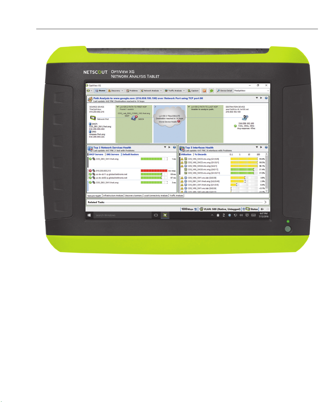
Introduction
Figure 1. OptiView XG Network Analysis Tablet with 10/100/1000Mbps/10Gbps Wired Enabled
4
Page 11
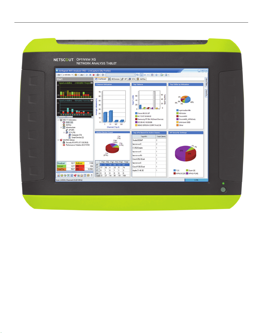
OptiView XG Network Analysis Tablet
Getting Started Guide
Figure 2. OptiView XG Network Analysis Tablet with Wireless Only Enabled
5
Page 12
Introduction
OptiView XG
Soft Case
SFP Adapter
AC Adapter
Power Cord
Shoulder Strap
Hand Strap
Batteries
Stylus
Getting Started
Flash Drive
Registration Card
Guide
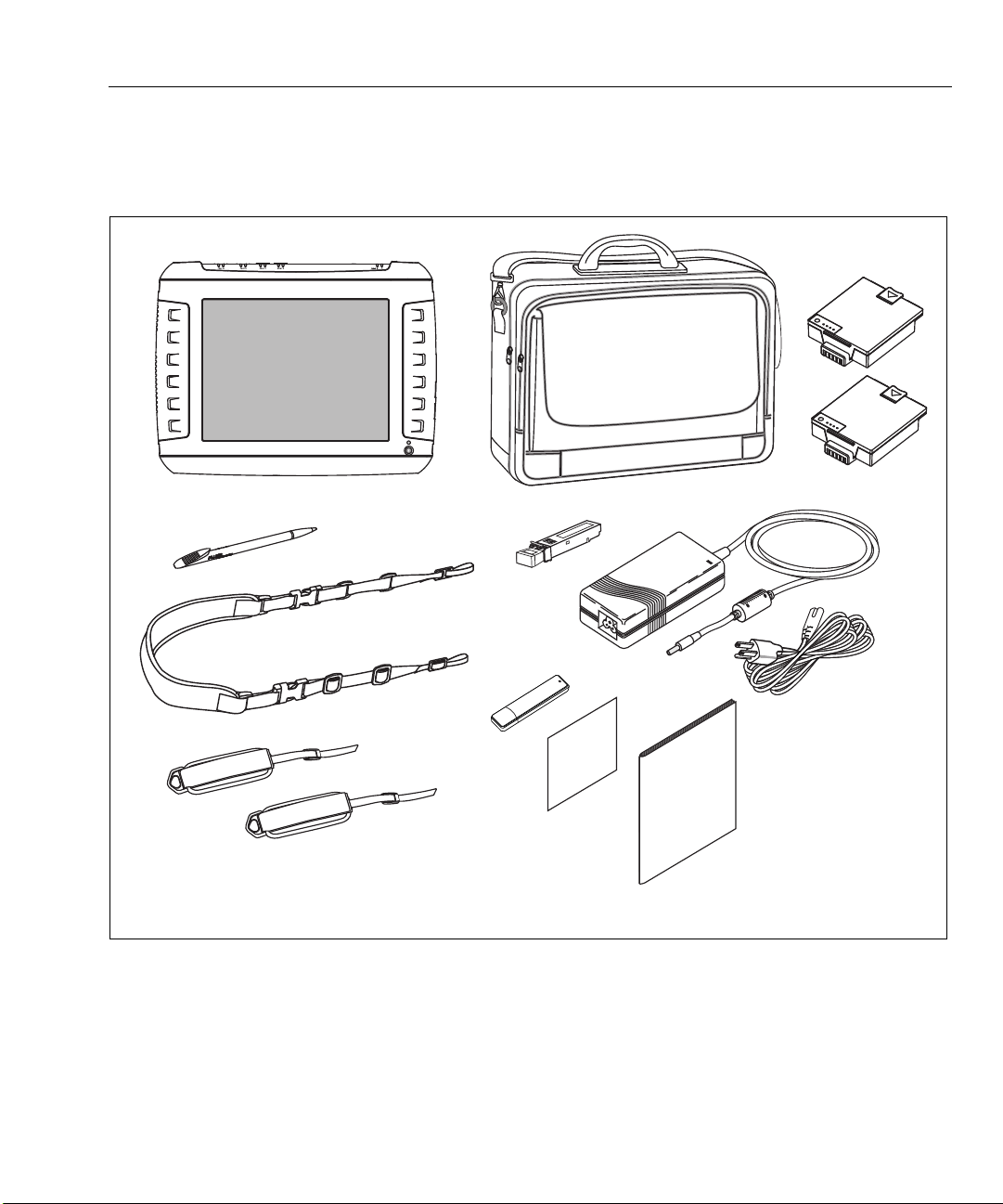
Package Contents
Verify that the following items are supplied with your OptiView XG Network Analysis Tablet in the 10/100/
1000Mbps/10Gbps wired only configuration.
Figure 3. Supplied Items
NOTE
If the wireless configuration is purchased, the AirMagnet user guides are provided. For the wireless only
configuration, the SFP adapter is not provided. For the 10-Gbps wired configuration, an additional 10Gbps SFP adapter is provided.
6
Page 13

OptiView XG Network Analysis Tablet
Getting Started Guide
Table 2. Supplied Items for Wired Only Configuration
Item Description Model Number
OptiView XG Network Analysis Tablet. —
1000BASE-SX SFP 1000BASE-SX SFP optical transceiver module (adapter), 850
OPV-SFP-SX
nm, 50 and 62.5 micron multi-mode.
Stylus Stylus for use on OptiView XG touchscreen. OPVXG-STYLUS
Batteries Set of two lithium-ion batteries with built-in charge
OPVXG-BATTERY
indicators. Provides approximately two hours of run time.
Hand and
Attach to the OptiView XG for easy carrying. OPVXG-STRAPS
Shoulder Straps
Soft Case Protective soft case. OPVXG-CCASE
AC Adapter Input: 90-264 VAC, 47-63 Hz, 2.0 A max
OPVXG-PS
Output: 19 VDC, 4.74 A, 90 W.
Caution: For safe operation, use only the supplied AC
adapter.
AC power cord Country-specific AC power cord (line cord). —
Getting Started
Guide
Flash Drive Includes Remote User Interface software, Help System, and
This document.
Getting Started Guide in multiple languages, PDF format.
—
—
Registration Card NETSCOUT can best serve you when you register online at
www.enterprise.netscout.com.
If you cannot register online, please fill out and return the
supplied registration card.
7
—
Page 14
Introduction
Esc
F1
F1
F1
F
1
F1
F1
F1
F
1
F1
F1
F
1
F
1
F1
F
1
F1
F1
!
1
@
2
#
3
$
4
%
5
Y
&
7
I
O
P
{
{
Q
Q
W
E
R
T
Y
U
I
O
P
{
{
A
Caps
Lock
S
F
D
G
H
J
K
L
:
;
“
‘
Ente
r
Enter
Z
Shift
X
V
C
B
N
M
<
,
>
.
?
/
?
/
POWER 1
POWER
2
LINK
TAP
1 PORT 1PORT 2
NETWORK PORTS
MONITOR PORTS
AB
Directional Antenna
with Mounting
10 Gbps Fiber Tap
Hard Drive in
ESD protective bag
Battery Charger Bundle
Keyboard
Hard Case
1 Gbps
Copper Tap
SFP Adapter
Omnidirectional
Antenna
Hardware
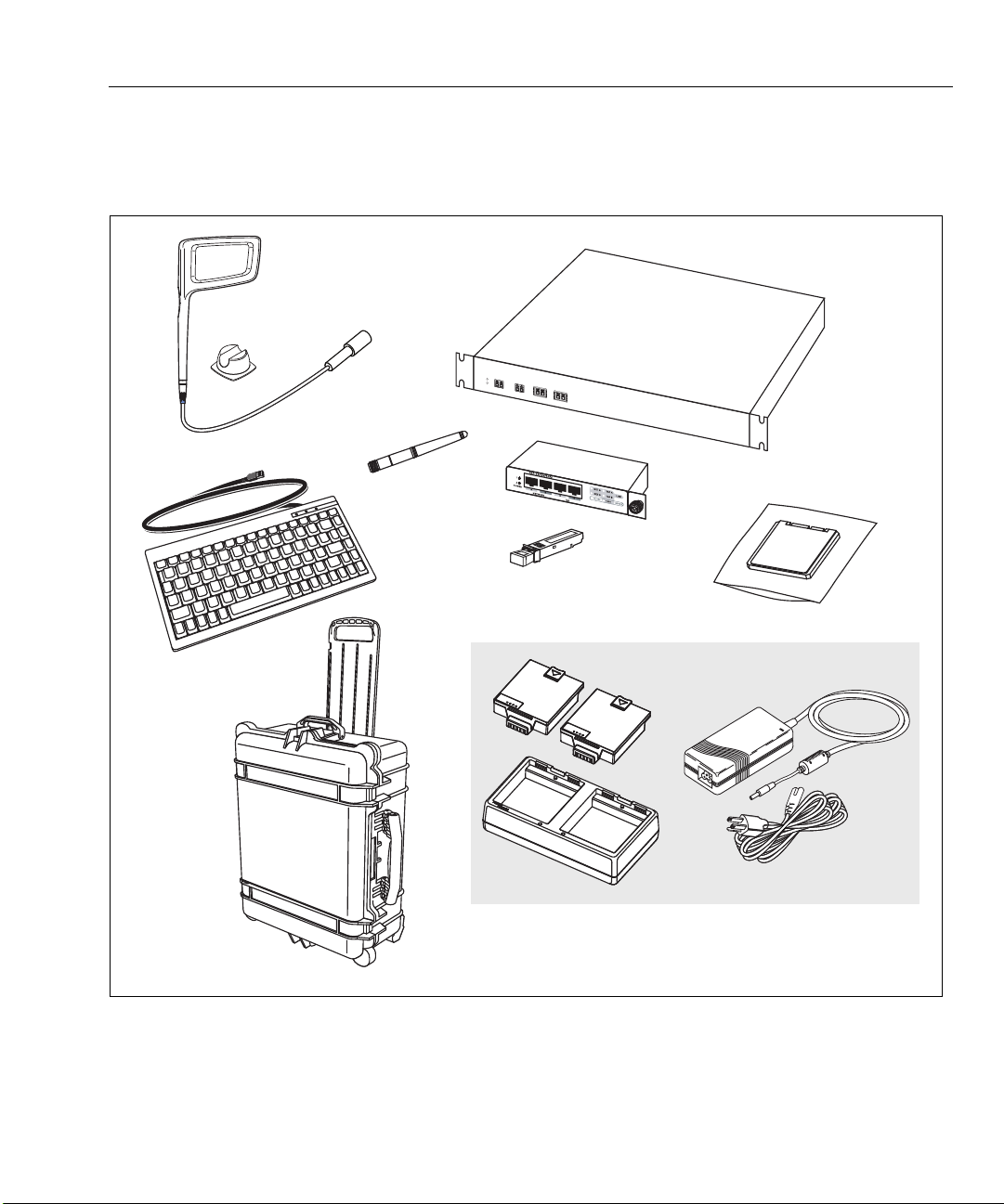
Optional Accessories
The following accessories were available when this manual was printed. For an updated list see
www.enterprise.netscout.com.
Figure 4. Optional Accessories
8
Page 15

OptiView XG Network Analysis Tablet
Getting Started Guide
Item Description Model Number
Directional
Antenna
Directional Antenna for use with AirMagnet WiFi Analyzer PRO
and Spectrum XT applications.
Table 3. Optional Accessories
OPV-DIRECT-ANT
Omnidirectional
Omnidirectional antenna for use with AirMagnet applications. OPV-OMNI-ANT
Antenna
Keyboard Small-footprint USB keyboard for connection to OptiView XG. OPVS2-KB
Hard Case Hard-sided carrying case. OPVXG-HCASE
Removable Hard
1
Drive
Tap, Fiber 10 Gbps in-line filtering fiber tap with two XFP any-to-any
Tap, Copper 1 Gbps in-line copper tap. Passive @ 10/100 Mbps, active @
Removable hard drive, supplied in static-resistive bag. OPVXG-RHD
FAXTAP1204SR-
ports.
10G
TAP-10/100/1000
1000 Mbps.
Battery Charger
Bundle
10G Fiber SFP+ SR
adapter
10G Fiber SFP+ LR
adapter
10G Fiber SFP+
LRM adapter
1G Fiber SFP SX
adapter
1G Fiber SFP LX
adapter
1G Fiber SFP ZX
adapter
100M Fiber SFP FX
adapter
Set of two battery packs, charging station, AC adapter, and line
cord.
10GBASE-SR SFP+ optical transceiver module (adapter), 850
nm multi-mode.
10GBASE-LR SFP+ optical transceiver module (adapter), 1310
nm single mode.
10GBASE-LRM SFP+ optical transceiver module (adapter), 1310
nm multi-mode.
1000BASE-SX SFP optical transceiver module (adapter), 850nm,
50 and 62.5 micron multi-mode.
1000BASE-LX SFP optical transceiver module (adapter), 1300
nm, 10 micron single mode.
1000BASE-ZX SFP optical transceiver module (adapter), 1550
nm, single mode.
100BASE-FX SFP optical transceiver module (adapter), 1310
nm.
OPVXG-BATT-KIT
OPVXG-SFP-PLUSSR
OPVXG-SFP-PLUSLR
OPVXG-SFP-PLUSLRM
OPV-SFP-SX
OPV-SFP-LX
OPV-SFP-ZX
OPV-SFP-100FX
1
Use standard ESD protection practices when handling this item.
Shipping Damage
If shipping damage has occurred, call the carrier immediately and file a claim. Then contact NETSCOUT (see
page 11) to arrange repair or replacement.
9
Page 16

Registering the OptiView XG
Registering the OptiView XG
To register, go to http://www.enterprise.netscout.com/registration. If you do not already have an account,
select the Create Account button to proceed.
You can also register the OptiView XG by filling out the registration card and sending it to NETSCOUT.
Registration provides the following benefits:
• Notification of software updates
• Three free telephone support incidences during the first 60 days of product ownership
• Access to the online Knowledge Base
• Web-based trouble ticket support
Registering the NETSCOUT AirMagnet Products
Customers of AirMagnet products are encouraged to register their products and take advantage of the
benefits of a “My AirMagnet” account.
Additionally, NETSCOUT Gold Support is our comprehensive support and maintenance program that offers
expanded coverage for all AirMagnet products.
To register AirMagnet products:
1. Go to http://airmagnet.netscout.com/support/register_product/
2. Enter the product serial number in the space provided. Leave the MAC address option unchecked.
3. Select whether you currently have a My AirMagnet account.
4. Click Next.
5. Complete the Product Registration form (including the Serial Key information).
6. Click Submit.
AirMagnet Gold Support Registration
Customers with Gold Support will receive a unique support serial number and serial key for each AirMagnet
product included in their Gold Support contract. The support serial number and serial key must be registered
in order for Gold Support to be activated. After registering the product, this can be accomplished in the
Registered Products section of your My AirMagnet account at:
http://airmagnet.netscout.com/my_airmagnet/public/registered_products
10
Page 17

OptiView XG Network Analysis Tablet
Getting Started Guide
Contacting NETSCOUT
Web: www.enterprise.netscout.com
For more contact information, visit our website.
Email: customercare@netscout.com
Phone: Toll free +1-844-833-3713; International 978-320-2150
11
Page 18
Context-Sensitive Help System
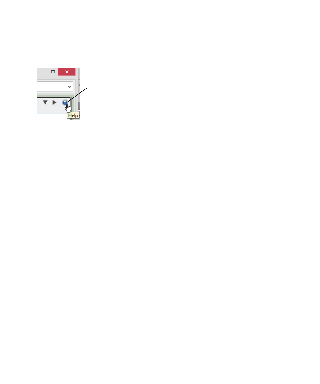
Show Help for the current screen
Context-Sensitive Help System
On the OptiView XG analyzer user interface, select the blue question mark to show help for the current
screen.
Figure 5. OptiView XG Help Button
AirMagnet Product Documentation
Each AirMagnet product includes the following documentation: ReadMe (PDF), Release Notes (PDF), User
Guide (PDF), and a User Guide in online help format. To locate documentation, go to:
• the Help menu within each application
• the product folder under C:\Program Files (x86)\AirMagnet Inc
within your AirMagnet.Netscout.com “My AirMagnet” account under “Documents > Drivers”.
12
Page 19
OptiView XG Network Analysis Tablet
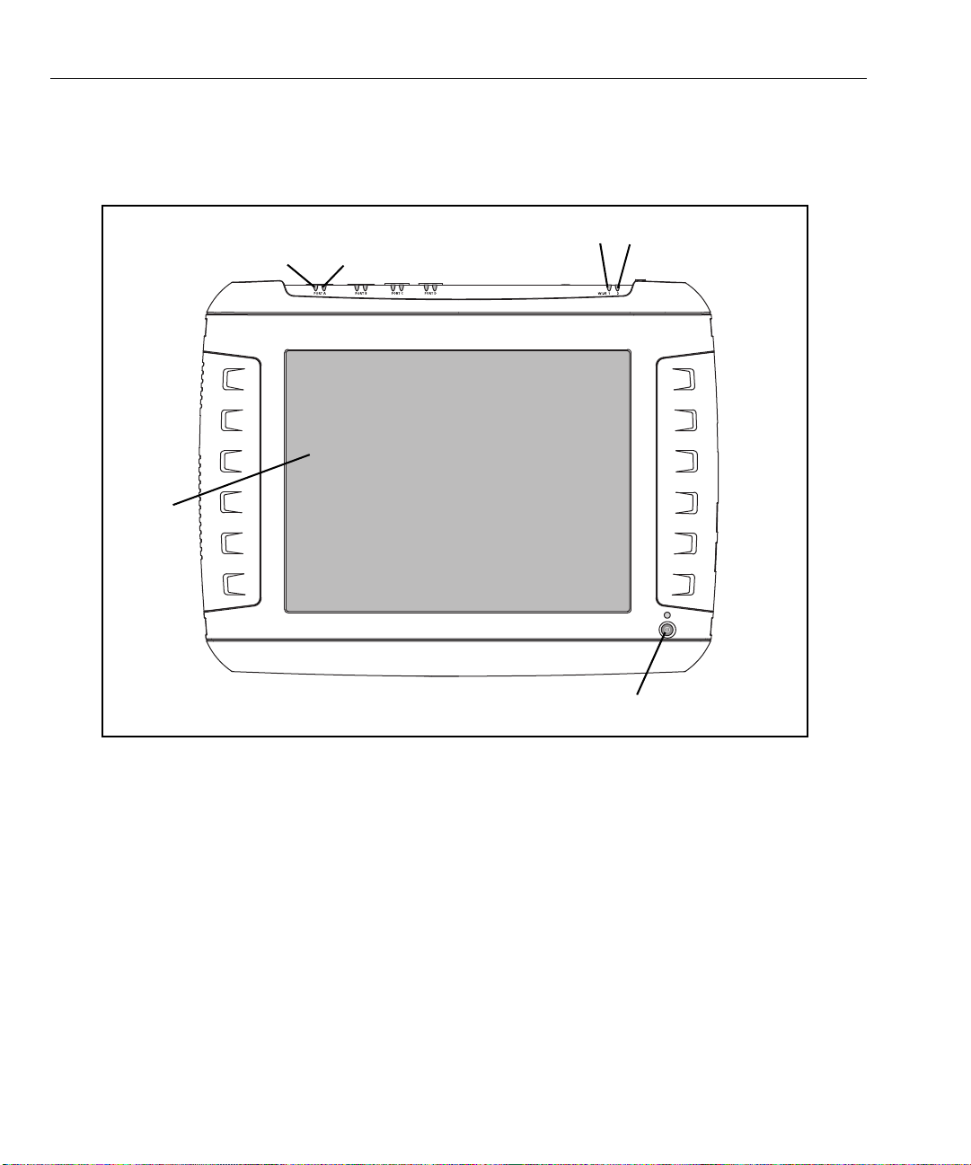
Power Switch
Display
Link Speed
Indicator
Link Utilization
Indicator
Wi-Fi Indicators
Getting Started Guide
Operating your OptiView XG
Connectors, Controls, and Indicators
• Link Speed Indicator, see page 25.
• Link Utilization Indicator, see page 25.
• Wi-Fi Indicators, see page 35.
• Power Switch, see page 18.
• Multi-Touch Display, see page 21.
13
Figure 6. Front View
Page 20
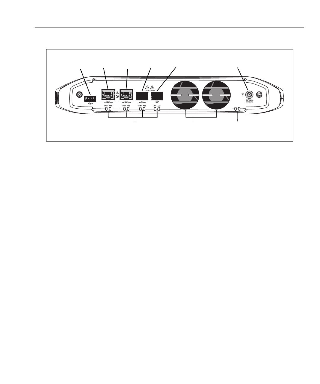
<View of network connectors>
Port A Port B Port C Port DUSB Port External Antenna Connector
Link Speed and Utilization Indicators Wi-Fi Status Indicators Fans
• USB Port, see page 42.
• Network Ports A, B, C, and D; see page 24.
• External Antenna Connector, see page 42.
• Link Speed Indicator, see page 25.
• Link Utilization Indicator, see page 25.
• Wi-Fi Indicators, see page 35.
Operating your OptiView XG
Figure 7. Top View
14
Page 21
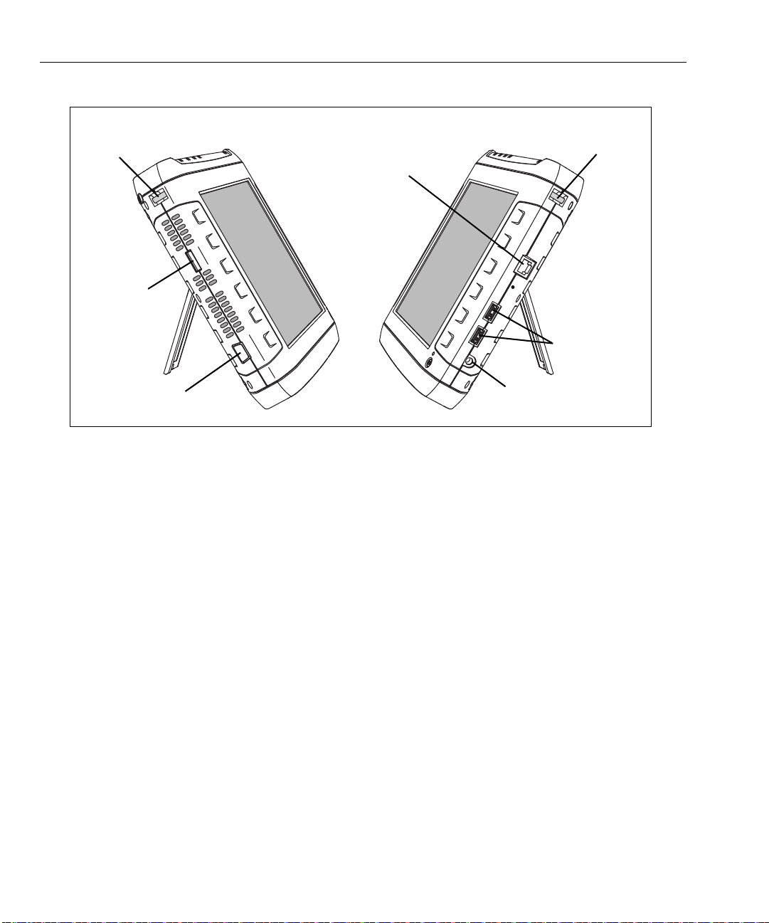
VGA Port
eSATA
Carry Strap
Management
USB Ports
Power Connector
Carry Strap
Port
Post
Post
Port
OptiView XG Network Analysis Tablet
Getting Started Guide
Figure 8. Left and Right Side Views
• Carry strap post, for connecting carry strap.
• eSATA connector, see page 42.
• VGA Port, see page 43.
• Management Port, see page 24.
• USB Ports, see page 42.
• Power Connector, see page 18.
15
Page 22
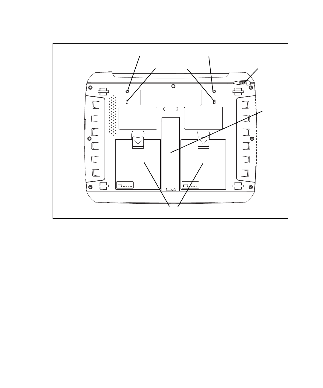
Stylus Dock
Stand
Batteries
Kensington Security Slots
Battery #2 Battery #1
Directional Antenna Connection Points
Operating your OptiView XG
• Batteries, see page 37.
• Stand, see page 17.
• Stylus and Dock, see page 17.
• Kensington Security Slot, see page 47.
Figure 9. Rear View
16
Page 23
OptiView XG Network Analysis Tablet
Getting Started Guide
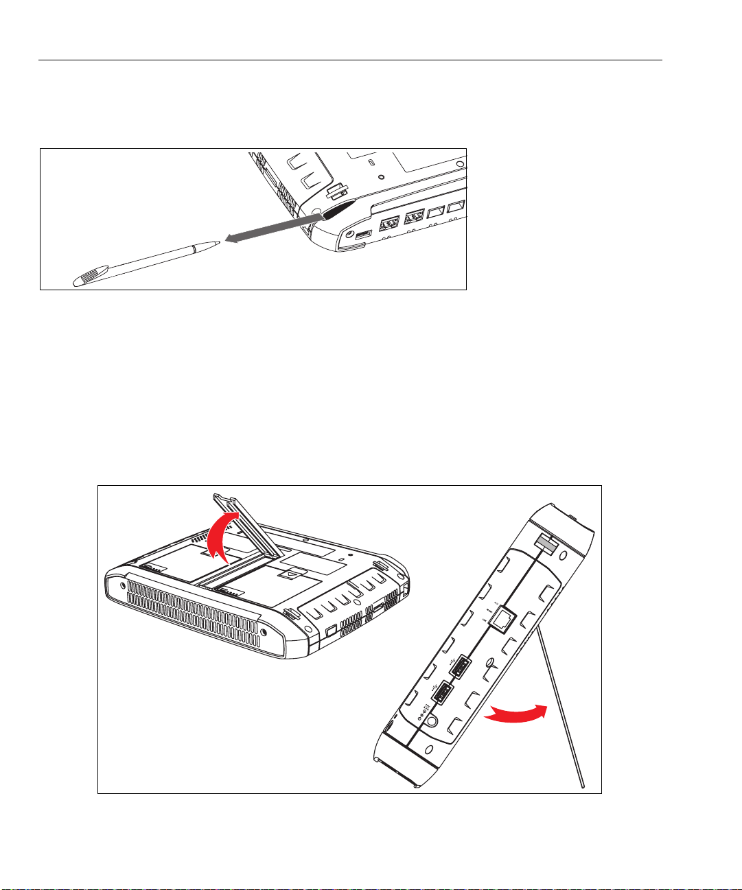
Stylus
The stylus is docked in the upper right corner of the rear panel. Slide it out to use it; slide it back in for
storage.
Figure 10. Stylus and Dock
The multi-touch screen is designed for use with a stylus. However, you can also use your fingertip. Your
fingernail or a stylus provide more accurate control than the pad of your fingertip. Use of sharp objects or
excessive pressure on the multi-touch screen may cause permanent damage.
See also: “Screen Use and Care” on page 21.
Extending the Stand
The stand is a convenient feature for desktop use. To extend the stand, pull at the recessed portion located at
the bottom of the stand. To retract the stand, push it back in until it snaps in place.
Figure 11. Extending the Stand
17
Page 24
Operating your OptiView XG
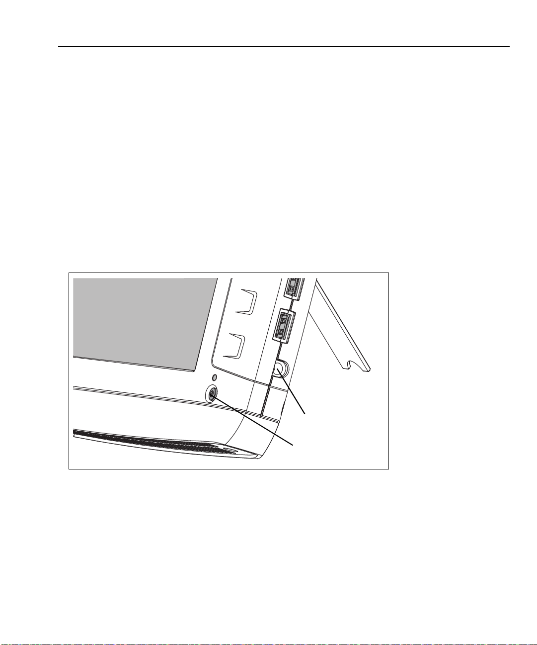
Power button
Power connector
Power Modes
Powering On
1. Connect the AC adapter to a power source and to the OptiView XG Network Analysis Tablet. See Figure 12,
“Powering On” for the location of the power connector and power button.The batteries are not fully
charged before shipment due to transportation regulations.
2. Charge the batteries to full capacity before disconnecting the AC adapter. Charge time is approximately
3 hours. Run time is approximately 2 hours with fully charged batteries.
If running wireless only, the run time is approximately 4 hours.
• If the OptiView XG is powered-on, see the Battery Status Window (see page 38) to verify that
batteries are fully charged.
• If the OptiView XG is powered-off use the Battery Charge Status LED (see
Charge Indicators on the batteries (see
3. Press the green On/Off button to power-on the OptiView XG.
page 38) to verify that batteries are fully charged.
page 37) or the Battery
Figure 12. Powering On
The OptiView XG will power-up. The following screens will be displayed during power up:
1. Blank screen.
2. NETSCOUT splash screen.
3. Operating system startup screens.
4. NETSCOUT desktop background.
5. The OptiView XG application.
18
Page 25

OptiView XG Network Analysis Tablet
Getting Started Guide
NOTE
If the wireless only configuration is purchased, the AirMagnet WiFi Analyzer PRO home screen is displayed
instead of the OptiView XG application which is shown below. (See Figure 2, “OptiView XG Network
Analysis Tablet with Wireless Only Enabled” ).
6. When power-on is complete, the default dashboard is displayed.
Figure 13. OptiView XG Home Screen
For more information, see “Context-Sensitive Help System” on page 12.
Sleep Mode
In the factory-default configuration, when you press the OptiView’s power button the Windows Sleep
sequence is activated, and the unit goes into a low power state. The Power/Charge LED indicator behavior is
described on
To resume from Sleep mode, press the power button.
19
page 37.
Page 26

Operating your OptiView XG
Two fully-charged batteries will last approximately 36 hours when the OptiView XG is in Sleep mode.
NOTE
Settings that you configure in the OptiView Settings screens are retained through Sleep and Shutdown
cycles. Discovery and Traffic Analysis data are not retained.
Powering-Off
If you plan to leave the OptiView XG in Sleep mode while unplugged from the AC adapter for an extended
period, power-off the OptiView XG to avoid fully discharging the batteries.
Use the typical Windows Shut Down procedure to power-off your OptiView XG tablet.
When the OptiView XG has been powered-off, battery life is determined by the internal discharge rate of the
lithium-ion batteries, which is approximately 5-10% per month.
See also: “Battery Life in Sleep or Shut down Modes” on page 39.
20
Page 27

OptiView XG Network Analysis Tablet
Getting Started Guide
Using the Touchscreen, Stylus, Keyboard, and Mouse
Screen Use and Care
Clean the touchscreen using a soft cloth that has been moistened with mild detergent. Do not spray liquid
directly on the touchscreen because the liquid could seep into the OptiView XG housing. Do not use harsh
cleaners on the touchscreen.
See also: “Connecting the OptiView XG to a Network” on page 24.
Windows Touchscreen Settings
The OptiView XG uses a standard Windows touchscreen driver. The Multi-Touch Screen supports Windows
multi-touch gestures such as flicks and right-click.
You can customize certain tablet PC features in Windows.
NOTE
Windows 10 uses a different interface for settings than Windows 7. To open the traditional Windows
Control Panel in Windows 10, right-click (or touch and hold) on the Start button in the lower left corner;
then, select Control Panel from the menu. You can also search for “control panel” in the Search Windows
box shown in Figure 14, “Windows Search Boxes” .
The Windows Control Panel and touchscreen settings can be accessed in any version of Windows by
searching for the setting keyword in the Windows search box.
Figure 14. Windows Search Boxes
To search for the settings you want to adjust:
1. In Windows 7, select the Windows Start button to open the search box.
In
Windows 10, the search box appears to the right of the Windows Start button .
2. Type in the keyword or name of the setting listed below to open the correct dialog box for that setting.
• To Calibrate the touch screen, search for the Tablet PC Settings dialog box. On the Display tab, select
the Calibrate... button, and then, follow the prompts.
• To adjust Pen and Touch settings, search for the Pen and Touch dialog box.
• To adjust Virtual Keyboard/Input Panel settings in Windows 7, search for the Tablet PC Settings
dialog box. On the Other tab, use the links to customize Pen and Touch and Virtual Keyboard (also
called Input Panel) settings.
• Refer to “Virtual Keyboard in Windows 10” on page 23 for an overview of the Windows 10 keyboard.
21
Page 28

Using the Touchscreen, Stylus, Keyboard, and Mouse
Virtual Keyboard
The virtual keyboard lets you type without a hardware keyboard. This is convenient when you are on-site with
the OptiView XG and a hardware keyboard is not connected.
NOTE
The Virtual Keyboards look different depending on whether you have Windows 7 or Windows 10 installed
on your OptiView XG.
Virtual Keyboard in Windows 7
1. Touch the left edge of the screen to reveal the edge of the virtual keyboard.
Note that you can drag the minimized keyboard up or down if it’s in your way.
Figure 15. Minimized Virtual Keyboard on an OptiView XG running Windows 7
2. When the edge of the keyboard appears, touch it again and it will come into full view. Touch the keys to
type. If desired, you can drag the keyboard to a different location on the screen.
Figure 16. Expanded Windows 7 Virtual Keyboard
3. Select the X to close the keyboard.
22
Page 29

OptiView XG Network Analysis Tablet
Getting Started Guide
Virtual Keyboard in Windows 10
1. Touch the keyboard icon in the Windows 10 task bar (at the bottom of the screen) to open the virtual
keyboard.
Figure 17. Virtual Keyboard button on an OptiView XG running Windows 10
Figure 18. Maximized Windows 10 Virtual Keyboard
2. Touch the icons circled in the image above to adjust the keyboard’s format and position.
3. Select the X to close the keyboard.
23
Page 30

Connecting the OptiView XG to a Network
<View of network connectors>
Port A Port B Port C Port DUSB Port External Antenna Connector
Link Speed and Utilization Indicators Wi-Fi Status Indicators
Connecting the OptiView XG to a Network
NOTE
For the wireless only configuration, go to “Establishing a Wireless Connection” on page 26.
You can connect the OptiView XG to a network via network ports A, B, C, or D, or via the built-in wireless
adapters.
The OptiView XG’s management port can be used for remote contr
network). This lets you control the analyzer from a management network while using the OptiView XG to test
a production network.
ol of the analyzer (from a separate
Establishing a Wired or Fiber Connection
Connect an appropriate cable from one of the OptiView XG’s network ports to the network that you want to
test. The OptiView XG will find the active network interface and obtain an IP address. Then it will begin
discovering the network.
Network Ports
The OptiView XG has the following network ports:
• Port A: RJ45 Ethernet connector, 10/100/1000 Mbps
• Port B: RJ45 Ethernet connector, 10/100/1000 Mbps
• Port C: 100/1000 Mbps Ethernet over fiber on standard SFP socket
• Port D: 10 Gbps Ethernet over fiber on standard SFP+ socket
• Management Port: RJ45 Ethernet connector, 10/100/1000 Mbps
Figure 19. OptiView XG Network Ports
24
Page 31

OptiView XG Network Analysis Tablet
Getting Started Guide
Caution
To prevent equipment damage, do not connect the OptiView XG Port A or Port B to a telephone line
or an ISDN line.
Link Speed and Utilization Indicators
There are two link status indicators for each network port: Link Speed (on the left) and Utilization (on the
right).
Table 4. Network Port Link Speed Indicator
Color Link Speed
Green 10 Mbps
Blue 100 Mbps
White 1000 Mbps
Magenta 10 Gbps
Table 5. Network Port Link Utilization Indicator
Color Link Utilization
Flashing Green 0% - 9%
Green 10% - 50%
Yellow 51% - 80%
Red 81% - 100%
Installing/Removing the SFP or SFP+ Fiber Adapter (Transceiver)
To install an SFP or SFP+ Fiber adapter, remove the protective cap from the adapter and slide the adapter into
Port C or Port D. To remove, gently pull the SFP’s bail. If the SFP has retention tabs, press and hold the tabs on
the sides of the adapter and pull it from the fiber port.
A list of supported SFP and SFP+ modules is given in the specifications on page 58. See
www.enterprise.netscout.com for a complete list of supported SFP and SFP+ modules.
25
Page 32

Connecting the OptiView XG to a Network
Wi-Fi Indicators
Establishing a Wireless Connection
OptiView XG Wireless Capabilities
Wireless capabilities are an option at time of purchase, or may be enabled after purchase. If you purchased
wireless capability and you reside in a country for which RF certification has been received, the Wi-Fi adapters
were enabled at the factory prior to shipment.
The OptiView XG Network Analysis Tablet includes internal wireless adapters and a spectrum analyzer
adapter. They are available to the OptiView XG application and AirMagnet mobility applications for wireless
network access and wireless LAN analysis and troubleshooting.
The OptiView XG application can use the Wi-Fi ada
and troubleshoot the LAN and wireless network.
The AirMagnet mobility product suite uses the Wi-Fi adapters and
comprehensive 802.11 and RF interference analysis as well as for site survey projects.
The OptiView XG tablet includes two Wi-F
use as a wireless port or can be used by the AirMagnet applications. Wi-Fi 2 and the spectrum analyzer
adapter are reserved for use only by AirMagnet applications.
Figure 20. Wi-Fi Indicators
When AirMagnet applications are launched, they will check for the presence of adapters and open a dialog
that indicates detected adapters. Check the desired adapter(s) for the current session. It should be noted that
AirMagnet products enable the use of multiple adapters for simultaneous channel scan functions. For more
information, see “configuring channel scanning for multiple adapters” in the AirMagnet User Guide.
i adapters and one spectrum analyzer adapter: Wi-Fi 1 is for general
pter for network access. Once connected, you can analyze
the spectrum analyzer adapter for
26
Page 33

OptiView XG Network Analysis Tablet
Getting Started Guide
Enabling the Wi-Fi Adapters
If NETSCOUT received approval to enable the Wi-Fi adapters for use in your country before your OptiView XG
was shipped to you, and you purchased a model with wireless capabilities, the Wi-Fi adapters are already
enabled.
If NETSCOUT received approval to enable the Wi-Fi adapters for use in your country after your OptiView XG
was shipped to you and you purchased a model with wireless capabilities, you can enable your Wi-Fi adapters
by contacting your sales representative and obtaining a power control key for a nominal fee. To determine
whether the Wi-Fi adapters are enabled and powered on, select the OptiView Power Control icon in the
system tray.
Figure 21. Power Control Icon
Wi-Fi Adapters Not Enabled
If the Wi-Fi adapters have not been enabled, a dialog will be displayed as shown below. To enable the wireless
capabilities, enter a power control key.
If NETSCOUT receives approval to enable Wi-Fi adapters in your country after you purchase the Op
you can call NETSCOUT Technical Assistance Center to obtain a power control key for a nominal fee. Please
see “Contacting NETSCOUT” on pag
Figure 22. Power Control Dialog
e 11.
tiView XG,
27
Page 34

Connecting the OptiView XG to a Network
The Wi-Fi adapters and the spectrum analyzer consume
small amounts of power, so it’s fine to leave them powered-on
even when operating on battery power.
Select the “Save and Restart” button to reboot the system and
make the changes effective.
Wi-Fi Adapters Enabled
If the Wi-Fi adapters are enabled, the OptiView Power Control application will open as shown below. Use the
application to manage power for the adapters you want to use.
Figure 23. Power Control Application
28
Page 35

OptiView XG Network Analysis Tablet
Getting Started Guide
Connecting to Wireless Networks in Windows
On the OptiView XG Network Analysis Tablet, you can view and connect to wireless networks the same way
you would on a typical Windows device.
NOTE
This section only applies to the OptiView XG Tablet user interface. It does not apply to the AirMagnet
applications. The Wi-Fi profile and security are configured separately on each AirMagnet application.
1. Select the wired or wireless networks list icon in the Windows task bar at the lower right corner of the
screen.
• Wired Windows 7
• Wired Windows 10
• Wireless Windows 7
• Wireless Windows 10
NOTE
The Network icons may appear in different colors depending on the version of Windows you are using, but
they are always located in the task bar at the lower right.
Figure 24. Location of Networks List Icon in the Windows Task Bar
29
Page 36

Connecting the OptiView XG to a Network
A pop-up displays the available networks.
Figure 25. Wireless Networks Pop-up List (Windows 7 left; Windows 10 right)
2. Select a network name from the list to enter security credentials and connect.
3. Select “Open Network and Sharing Center” (in Windows 7) or “Network settings” (in Windows 10) to
manage your wired and wireless connection profiles in Windows..
Figure 26. Network Settings (Windows 7 left; Windows 10 right)
30
Page 37

OptiView XG Network Analysis Tablet
Expand/collapse arrow
If the wireless adapters have not been enabled,
this will say “Disabled.”
Getting Started Guide
Managing Wi-Fi on an OptiView XG Tablet with Windows 7
See “Managing Wi-Fi on an OptiView XG Tablet with Windows 10” on page 33.
NOTE
This section only applies to the OptiView XG Tablet user interface. It does not apply to the AirMagnet
applications. The Wi-Fi profile and security are configured separately on each AirMagnet application.
1. Select the Status button, which is located at the bottom of the screen. The configuration panel will open.
Figure 27. Status Button
2. Collapse the Network Port section and expand the Wireless Port section using the arrows at the right.
Figure 28. Network Port Status
3. Select the word “Disconnected.” The OptiView Settings screen will be displayed, with the Wireless icon
highlighted at the left edge of the screen.
Figure 29. Wireless Port Settings
31
Page 38

Connecting the OptiView XG to a Network
4. Select the Manage Wireless Networks button, and follow the Windows prompts.
Figure 30. Manage Wireless Networks Button
The OptiView XG connects to networks based on the profile preferences you create.
32
Page 39

OptiView XG Network Analysis Tablet
Expand/collapse arrow
If the wireless adapters have not been enabled,
this will say “Disabled.”
Getting Started Guide
Managing Wi-Fi on an OptiView XG Tablet with Windows 10
NOTE
This section only applies to the OptiView XG Tablet user interface. It does not apply to the AirMagnet
applications. The Wi-Fi profile and security are configured separately on each AirMagnet application.
Viewing Wireless Settings with Windows 10
1. Select the Status button, which is located at the bottom of the screen. The configuration panel will open.
Figure 31. Status Button
2. Collapse the Network Port section and expand the Wireless Port section using the arrows at the right.
Figure 32. Network Port Status
3. Select the word “Disconnected.” The OptiView Settings screen will be displayed, with the Wireless icon
highlighted at the left edge of the screen.
Figure 33. Wireless Port Settings
33
Page 40

Connecting the OptiView XG to a Network
The Wireless Settings screen displays additional information regarding the current wireless status.
Figure 34. Windows 10 Wireless Settings
Managing Wireless Network Profiles with Windows 10
1. Select the Windows Start button in the lower left corner of the screen, and then, select Settings.
2. In the Windows 10 Setting menus, select Network & Internet.
Figure 35. Windows 10 Network & Internet Settings
3. Select a wireless network to manage its credentials.
34
Page 41

OptiView XG Network Analysis Tablet
Getting Started Guide
Wi-Fi Indicators
Each of the two Wi-Fi adapters has a single link status indicator. The LED illuminates when the Wi-Fi adapter is
in use. The LED’s color indicates the link speed (or that the Wi-Fi adapter is in use by an AirMagnet
application). The LED flashes to indicate traffic is present on the link.
Table 6. Wi-Fi Indicator
Color Link Speed Standard
Green up to 11 Mbps 802.11b
Blue up to 54 Mbps 802.11a/g
White up to 300 Mbps 802.11n/ac, with one or two spatial
streams
Magenta 450 Mbps or more 802.11n/ac, with three spatial streams
(3x3)
Amber Wi-Fi adapter is in use by an AirMagnet application
35
Page 42

Configuring the OptiView XG for Use with Your Network
a
b
Configuring the OptiView XG for Use with Your Network
1. If your network uses a MAC access list, you will need to add the OptiView XG’s MAC addresses to the list.
See the OptiView XG online help for more information.
2. Configure SNMP community strings and/or credentials to allow the OptiView XG to fully discover and
analyze your network.
a. Select the top left OptiView button.
b. Select the OptiView Settings button.
Figure 36. OptiView Settings
c. Select the Discovery button.
Figure 37. Discovery Settings
d. Select the SNMP Configuration tab.
e. Add SNMP v1 and v2 community strings and/or add SNMP v3 credentials. Select the Help button on
the screen for more information.
f. Select the Extended Discovery Ranges tab to enable discovery of networks beyond the broadcast
domain (off-net networks). Select the Help button on the OptiView Settings screen for more
information.
36
Page 43

OptiView XG Network Analysis Tablet
Getting Started Guide
Operating the OptiView XG on Battery Power
Battery Operation
The OptiView XG Network Analysis Tablet has two lithium-ion batteries. The batteries are installed into the
back of the OptiView XG.
The OptiView XG will run approximately 2 hours using fully-charged batteries. You can hot-swap spare
batteries (one at a time if the AC adapter is not connected) to extend run-time.
NOTE
The batteries will last approximately 4 hours with the Wireline Ports turned Off and the wireless adapters
turned On. See
Charging the Batteries
Before running the OptiView XG Network Analysis Tablet on batteries, connect the AC adapter to the OptiView
XG and charge the batteries. Charge time is approximately 3 hours.
Power/Charge Indicator
“Enabling the Wi-Fi Adapters” on page 27.
The LED next to the OptiView XG power button indicates the power on/off state and the battery charge status.
Table 7. Power/Charge Indicator
LED Color LED State Description
Green On The OptiView XG is powered-on. Use the battery status window to
determine battery charge state. See instructions on page 38.
Yellow Flashing The OptiView XG is in sleep mode or powered-off.
The AC adapter is connected, and the batteries are charging.
Yellow On The OptiView XG is in sleep mode or powered-off.
If the AC adapter is connected, the batteries are fully charged.
Off Off The OptiView XG is powered-off (shutdown, not in sleep state) and the
AC adapter is disconnected.
37
Page 44

Operating the OptiView XG on Battery Power
Press test
button
View charge
indicators
Battery #2 Battery #1
or
Running on battery
power.
Running on AC
power.
Displaying the Battery Charge Status Window
1. The battery status icon is located in the Windows system tray. It appears as a battery, a charging battery,
or an electrical plug. Select the icon to open the battery status window.
Figure 38. Battery Status Icon
2. The estimated battery capacity is displayed.
Figure 39. Battery Status Window
3. Touch (or click) the screen outside the battery status window to close the battery status window.
Battery Charge Indicators (on batteries)
The four LEDs on the back of each battery indicate the battery’s approximate charge. Press and release the
test button. Each illuminated LED indicates an additional 25% of available charge. When the battery’s charge
level is less than 10%, the left-most LED flashes.
Figure 40. Battery Charge Indicators
38
Page 45

OptiView XG Network Analysis Tablet
<graphic of battery removal>
1
2
3
Getting Started Guide
Replacing/Hot Swapping the Batteries
To remove a battery, (1) press the release clip and (2) pivot the battery out from the OptiView XG case. To
replace, pivot the battery in and press until it snaps into place.
Figure 41. Battery Removal and Replacement
When the AC power adapter is not connected, the OptiView XG is powered by whichever battery contains the
most charge. When the batteries have equal amounts of charge, the OptiView XG is powered by both
batteries.
The batteries can be hot-swapped. Replacing one battery wil
long as the other battery is capable of powering the OptiView XG.
An optional battery kit is available (see page 7). It contains two batteries, a char
adapter for powering the charging station.
Battery Life in Sleep or Shut down Modes
Two fully-charged batteries will last approximately 36 hours when the OptiView XG is in Sleep mode.
If you plan to leave the OptiView XG in Sleep mode whil
period, power-off the OptiView XG to avoid fully discharging the batteries.
When the OptiView XG has been powered-off (using Windows Shut d
internal discharge rate of the lithium-ion batteries, which is approximately 5-10% per month.
39
l not interrupt the OptiView XG’s operation as
ging station, and an AC
e unplugged from the AC adapter for an extended
own), battery life is determined by the
Page 46

Operating the OptiView XG on Battery Power
Battery Care
To maximize the life of lithium-ion batteries, avoid frequent full discharges. Partial discharges with frequent
recharges will make the batteries last longer. Lithium-ion battery technology does not suffer from the
“memory effect,” so recharge the batteries whenever it’s convenient. Avoid storing the batteries in a hot
environment. For optimal long-term storage, store at about 50% charge, in a cool place.
Extending Battery Operating Time
In its default configuration, the OptiView XG will operate for approximately two hours with fully-charged
batteries.
When only using the wireless adapters to connect to the network (not using Network Ports A, B, C, or D) you
can approximately double operating time by switching off power to the network ports. You may want to do
this when using the following (optional) applications for an extended period of time for field operations:
• AirMagnet WiFi Analyzer PRO
• AirMagnet Spectrum XT
• AirMagnet Survey PRO
To Switch Off Power to Network Ports A, B, C, and D
1. Select the OptiView Power Control icon from the System Tray.
40
Page 47

OptiView XG Network Analysis Tablet
Getting Started Guide
The OptiView Power Control screen will appear, as shown.
2. Switch off Wireline Ports A, B, C, and D. This will approximately double battery
operation time.
3.The system must reboot to make the change. Select the Save
and Restart button.
NOTE
Remember to switch on Wireline Ports A, B, C, and D before attempting to use the Network Ports!
41
Page 48

Connecting External Devices
Connecting External Devices
Keyboard, Mouse, Flash Drive, Printer, and Other USB Devices
You can connect an external keyboard, mouse, flash drive, hard drive, or printer to the OptiView XG’s USB
ports. Windows will automatically recognize the devices and make them ready to use. See page 14 and
page 15 for the locations of the USB ports.
External eSATA Hard Drive
You can connect an external eSATA drive using a shielded cable with a length of one-half meter or less.
Restart Windows or use Control Panel>Device Manager>Action>Scan for Hardware Changes to cause
Windows to recognize the drive. Note that the eSATA connector does not supply power. An external power
supply must power the eSATA drive. See
External Antenna
The OptiView XG normally uses its internal antennas. When using AirMagnet applications (e.g. for locating
rogues or performing spectrum analysis) you can attach and switch to an external antenna. See page 24 for
the location of the external antenna connector.
The optional omni-directional antenna offers better scanning sensitivity when using AirMagnet Spectrum XT.
page 15 for the location of the eSATA port.
The optional directional antenna can be used in conjunction with AirMagnet Wi-Fi Analyzer PRO and
Spectrum XT applications for increasing signal sensitivity when locating devices.
The directional antenna can be attached to the OptiView XG as shown in Figure 42, “Attaching and Swiveling
the Directional Antenna.”
42
Page 49

1
2
3
OptiView XG Network Analysis Tablet
Getting Started Guide
Figure 42. Attaching and Swiveling the Directional Antenna
Power Connector
Connect only the supplied AC adapter to the power connector. Connection of any other power source may
damage the OptiView XG. See page 18 for the location of the power connector.
VGA Port for External Monitor
You can connect an external monitor or projector to the VGA port. When connecting to a projector, go to the
Windows Control Panel and select Connect to a projector under the Hardware and Sound heading. See
page 15 for the location of the VGA port.
43
Page 50

Controlling the OptiView XG from a Remote Computer
Controlling the OptiView XG from a Remote Computer
NOTE
This section only applies to the OptiView XG user interface. It does not apply to the AirMagnet
applications.
The Remote User Interface application lets you initiate remote sessions with OptiView units over a TCP/IP
connection. The software includes a browser that helps you easily find OptiView units and initiate remote
sessions.
Remote PC Requirements
Operating Systems:
• Windows 7 Professional with SP1, 32 bit and 64 bit
• Windows 8.1 (32 bit and 64 bit)
• Windows 10
Operating System Languages:
• English, German, Japanese, Simplified Chinese
Installing the Remote User Interface
The remote user interface software may be installed from the supplied OptiView Resource flash drive, or from
the OptiView XG's web server home page.
Install from Flash Drive
To install from the flash drive, insert the flash drive in the remote PC’s USB port and follow the prompts.
Install from the OptiView XG’s Home Page
To view the OptiView XG's Home page, enter the OptiView XG's IP address in your PC's web browser. Then
select the Install Remote UI button.
Using the Remote User Interface to Access the OptiView XG User Interface
Launch OptiView Browser
The first step in using the Remote User Interface is to launch the OptiView Browser. Double-click the desktop
icon or select it from the Windows Program Menu. It is in the NETSCOUT program group. The OptiView
Browser will launch, and a list of the analyzers in the local network will be displayed.
44
Page 51

OptiView XG Network Analysis Tablet
Getting Started Guide
Initiate a Remote Session
To initiate a remote session with an OptiView, double-click it in the search results window.
To see an OptiView that is not in the broadcast domain, ent
the OptiView Browser.
Figure 43. OptiView Browser Window
Once you’ve established a connection, you can close the OptiView Browser window if desired. This will not
terminate the remote session.
er the IP address of the unit in the search bar of
Encrypting Data Over the Remote User Interface
A computer can initiate a remote session with an OptiView (see page 44). Data sent to and from the remote
analyzer can be encrypted. The OptiView XG uses the Advanced Encryption Standard (AES) 128 bit encryption
algorithm. The encryption key can be entered in Hex or ASCII. ASCII is provided for ease of remembering the
encryption key. An encryption key containing less than 128 bits (16 ASCII characters) will be padded with 0's.
When an encryption key has been set, each user attempting to open a remote UI session with t
XG will be prompted to enter the encryption key. When a remote encrypted session has been established via
a remote PC, the encryption key will be remembered on the remote PC (and it will not have to be entered
again).
he OptiView
Caution
For security reasons, encryption should be set directly on the OptiView XG and not through a
remote session. A remote UI could be capturing packets (and the transmitted encryption key) while
another remote UI is setting the data encryption.
45
Page 52

To Set Up Remote User Interface Encryption
1. Select the Link Status button.
2. Select the Access button.
3. Select the Remote Access tab.
Controlling the OptiView XG from a Remote Computer
Figure 44. Remote Access Settings
4. Press the Enter Encryption Key button.
5. Select ASCII or Hexadecimal and enter the key. This key will be required when a remote user attempts to
initiate a remote session.
You can clear the encryption key by pressing the Clear Key button.
Remote Connection Termination
To terminate a remote connection, close the OptiView Remote User Interface window on the remote
computer.
46
Page 53

OptiView XG Network Analysis Tablet
Kensington Security Slot
Getting Started Guide
The remote connection will be terminated if the OptiView XG’s MAC or IP address is changed, encryption is
changed, cable test is executed, the OptiView XG is switched to receive-only mode, or if the TCP/IP session is
terminated for any reason.
Security
It is common practice to leave the OptiView XG powered-on and connected to a network. This lets you
become familiar with devices on the network and normal traffic patterns. However, it is important to secure
the OptiView XG from theft and unauthorized use.
You can physically secure the OptiView XG in place using a Kensington lock. You can lock the OptiView XG by
locking Windows. And you can create user accounts with specific privileges.
Physical Security: Kensington Lock
Kensington security slots are provided on the OptiView XG housing. You can reduce the chance of theft by
purchasing a Kensington lock and using it to secure the OptiView XG in place.
Figure 45. Kensington Security Slot
Controlling Access to the OptiView XG
Locking Windows
When the OptiView XG is connected to a network and running, and you want to leave it unattended, you can
restrict access by locking Windows. Press Ctrl+Alt+Del and choose Lock the computer. However, this only
provides protection if you have set up a user account in Windows. Otherwise, the OptiView XG can be
unlocked by pressing the Enter key.
OptiView XG User Accounts
To control access to certain features of the OptiView XG, set up a User Account for each user. Permissions can
be set for each user. The admin account must be enabled prior to setting up additional user accounts.
47
Page 54

To Set Up User Accounts
1. Select the Link Status button to display the OptiView Settings screen.
2. Select the Access button.
3. Select the User Accounts tab.
Security
4. Expand the Administrators tree and select the admin account.
Figure 46. User Accounts Tab
5. Select the Create Password button and enter a password. The password field can be up to 40 characters
in length. All characters (including spaces) are allowed for the password field.
48
Page 55

OptiView XG Network Analysis Tablet
Getting Started Guide
6. Select the Enabled check box under User Account Properties.
Choose options under User Account Properties by checking the check boxes. Normally, all of the boxes are
selected for the administrator account. See the OptiView XG online help for descriptions of the User Account
check boxes.
7. Select the Apply b
utton.
8. Be sure to select the Enable User Accounts with authentication and authorization check box! When this
box is not selected, all user accounts are disabled.
• You may now create additional user accounts if desired. Select the guest account if you’d like to use it, or
select the Add button to create new accounts. The Account name and password fields can be up to 40
characters in length. All characters (including spaces) are allowed for both the Account and password
fields.
9. Select the OK button.
The user name (“admin” in this case) is di
Figure 47. User Name in Title Bar
splayed in the OptiView title bar.
An icon is displayed to the left of an account name to indicate that the user is logged-in.
Figure 48. Logged In Icon
To log off, close the OptiView application by selecting the “X” in the upper right corner or by typing Alt+F4. You
will need to log in (as admin or a user) whenever you re-start the OptiView XG Network Analysis Tablet or the
OptiView application.
• You can create up to 32 user accounts.
• For remote users, the encryption challenge occurs before the login challenge.
49
Page 56

Removing and Replacing the Hard Drive
1
2
3
Removing and Replacing the Hard Drive
The hard drive can be removed from the OptiView XG for secure data management.
Caution
To prevent damage to the OptiView XG and/or the removable hard drive, use standard ESD
(electrostatic discharge) control procedures and equipment.
Removing the Hard Drive
The analyzer’s “Computer name” is stored on the hard drive. You can view the Computer name by following
the instructions in “Changing the Computer Name” on page 51. If desired, make note of the analyzer’s
Computer name so you can restore it after replacing the hard drive.
1. Power-off the OptiView XG by selecting Shut down in Windows.
2. Disconnect all cables from the OptiView XG.
3. Use a Phillips screwdriver to remove the two screws that secure the bottom panel.
4. Slide the hard drive out.
Figure 49. Replacing the Hard Drive
Replacing the Hard Drive
To replace the hard drive, reverse the preceding procedure.
50
Page 57

OptiView XG Network Analysis Tablet
Getting Started Guide
The touchscreen calibration data is stored on the hard drive. You will need to re-calibrate the touchscreen
after replacing the hard drive. See
“Windows Touchscreen Settings” on page 21.
Changing the Computer Name
The analyzer’s name is stored on the hard drive. You can change the analyzer’s name as follows.
In Windows 7:
1. Select the Start button.
2. Right-click (or touch and hold) Computer.
3. Select Properties.
4. Select Change settings in the Computer name, domain, and workgroup settings section.
5. Type in the new name, and select Apply.
In Windows 10:
1. Right-click (or touch and hold) on the Windows Start button in the lower left corner.
2. Select System.
3. Select Change settings in the “Computer name, domain, and workgroup settings” section.
4. Type in the new name, and select Apply.
Cleaning
Clean the OptiView XG housing, the touchscreen, and the batteries using a soft cloth that has been moistened
with mild detergent. Dry with a soft cloth. Do not spray liquid directly on the OptiView XG or the batteries. Do
not use harsh cleaners. Do not immerse.
51
Page 58

Troubleshooting
Troubleshooting
If the OptiView XG is not operating as expected, refer to this table for possible causes and solutions.
Table 8. Troubleshooting Guide
Problem Possible Cause & Solution
Cannot establish a network connection. The OptiView XG’s MAC addresses have not been added to
the network’s MAC access list.
The OptiView XG fails to get an IP
address.
Cannot establish a Wi-Fi connection. Enable Wi-Fi adapters. See page 26.
Cannot establish a network connection
on network ports A, B, C, or D.
The OptiView XG is not reporting all of
the expected networks, devices, and
related detail.
There may be no connectivity to a DHCP server on the link.
This could be caused by a DHCP server that is not
responding to requests, in which case you would want to
investigate the health of the DHCP server.
If the analyzer is connected to a trunk port, ensure that the
selected VLAN has connectivity to an operational DHCP
server, or switch to a different VLAN.
Instructions for switching to a different VLAN:
1. Select the Link Status button. This opens the OptiView
Network Port Settings screen.
2. In the Active VLAN Configuration section, select a VLAN
that has connectivity to a DHCP server.
3. Select the OK button at the bottom of the screen.
Enable the Network Ports by switching on power to Network
Ports A, B, C, and D. See page 40.
To ensure successful discovery both on-net and off-net, it is
critical that you configure Discovery. Select the OptiView
button (in the upper left corner of the display), then select
the OptiView Settings button. Select the Discovery button
(at the left side of the screen).
1. To ensure access to the information (SNMP-MIBs) on the
devices' SNMP agent, configure the SNMP credentials on the
SNMP Configuration tab.
2. Often the devices' SNMP agents are connected to a
different subnet than the one to which the OptiView is
connected. These SNMP or Management subnets need to
be configured on the Extended Discovery Ranges tab.
3. To allow the OptiView to discover networks beyond the
subnet to which it is connected, configure the remote
subnets for discovery using the Extended Discovery
Ranges tab.
52
Page 59

OptiView XG Network Analysis Tablet
Getting Started Guide
Windows Restore Options
In the event the Windows operating system becomes unstable, there are two methods for restoring stability.
• Windows System Restore restores the Windows configuration to an earlier point in time without erasing
your data files.
• Windows System Recovery erases all data files and returns the Windows system to its original condition.
Instructions are provided for backing up your data files before they are erased.
Windows System Restore
The Windows operating system creates a restore point whenever you install new software. This lets you
restore the Windows configuration to an earlier point in time if desired. For example, if you install a driver
that when accessed, causes the system to hang, you can restore the Windows operating system using
Windows System Restore.
Restoring Windows Configuration from a Previous Windows 7 Restore Point
1. Select the Windows button, then select Control Panel.
In Windows 10, right-click (or touch and hold) on the Windows Start button in the lower left corner,
and then, select Control Panel from the menu.
2. In the search box, type System Restore.
3. Select Restore system files and settings from a restore point.
4. Follow the prompts.
Windows System Recovery
In the event the OptiView XG’s operating system becomes unstable, and you want to return the OptiView XG
to its factory default condition, you can restore the hard drive using the System Recovery utility. This will
effectively erase changes that were made since the OptiView XG left the factory. It will leave the OptiView XG’s
operating system and file system in a known, working state.
Caution
Performing a System Recovery will
• Erase all report, capture, and other data files
• Erase all OptiView XG user accounts and passwords
• Remove all user-installed applications
• Return the OptiView XG to its factory default configuration
The OptiView XG’s MAC address, purchased software options, and OptiView Power Control settings will be
preserved.
53
Page 60

Windows Restore Options
Caution
The OptiView XG could be rendered inoperable if the System Recovery process is interrupted. The
AC adapter (not batteries) should be used to power the OptiView XG during the recovery process.
Windows 7 Back Up and Recovery Procedure
NOTE
The following describes Windows 7 procedures. If you have Windows 10 installed on your OptiView XG,
skip to
Back Up Your Files
If you want to keep any files that currently exist on the OptiView XG’s hard drive, use Windows Backup to save
them to an external drive. You will need to deselect the “postgres” user account from the backup.
1. Select the Windows button, then select Control Panel.
Set the view control to View by: Small icons.
2. Select Backup and Restore.
Note that if you have previously set up a backup, the “Set up backup” button will not appear on this
screen. In that case you will need to choose Control Panel>Recovery>Advanced recovery
methods>Reinstall Windows>Back up now and then proceed to step 5.
page 55.
3. Select Set up backup.
4. Choose an external destination drive for the backup.
5. At the screen that says “What do you want to back up?” select Let me choose and select Next.
6. At the “What do you want to back up?” screen deselect postgres’s Libraries and deselect Include a system
image....
7. At the “Review your backup settings” screen ensure that OptiView’s Libraries are included and postgres’s
Libraries are not included.
8. Select Save settings and run backup.
9. When the backup completes, disconnect the external drive from the OptiView XG.
Recover Windows System Files
1. Disconnect all cables from the OptiView XG except the AC adapter, the keyboard, and the mouse.
2. Restart the OptiView XG.
3. When the NETSCOUT splash screen appears, press the F8 key multiple times.
Advanced Boot Options screen will appear. Verify that Repair Your Computer is selected, then press
4. The
Enter.
54
Page 61

OptiView XG Network Analysis Tablet
Getting Started Guide
5. You can now use the mouse to make your selections. Follow the prompts to choose a language.
6. At the User name and Password window, select the drop-down selector.
7. Select OptiView as the User name. You do not need to type anything in the Password box unless you have
created a password for this user.
8. Select OK.
9. At the
The recovery image will be written to the disk, and the old operating system’s directory will be renamed
C:\Windows.old. The C:\Windows.old directory consumes several gigabytes of storage space on the disk.
Verify that you have already saved any data files you need, then use the Windows Disk Cleanup tool to delete
all files (including hidden system files) in the C:\Windows.old directory, as described below.
Choose a recovery tool window, choose Reinstall Windows.
Post-Recovery File Clean-Up
1. Select the Windows Start Button, then type “free up disk space” in the search box.
2. Choose Free up disk space by deleting unnecessary files.
3. In the Drive Selection window, select the C: drive and wait for scanning to complete.
4. Select the Previous Windows installation(s) check box.
5. Select the Temporary Windows installation files check box.
6. Select or deselect other check boxes as desired.
7. Select OK.
8. Select Delete Files. The selected files will be deleted.
9. If you previously backed up data files to an external drive, connect the drive and use Windows Backup
and Restore to restore your data files.
Windows 10 Back Up and Recovery Procedure
Back Up Your Files
1. In Windows 10, select the Windows Start button in the lower left corner of the screen.
2. Select Settings, and then Update & security.
3. On the left side, select Backup.
4. Touch Add a drive to choose an external destination drive for the backup.
5. Follow the prompts to save your backup.
55
Page 62

Windows Restore Options
Recover Windows System Files
NOTE
The following process requires that you have a physical keyboard plugged into your OptiView XG Tablet
(see “Connecting External Devices” on
1. In Windows 10, select the Windows Start button in the lower left corner of the screen.
2. Select Power.
3. Hold Shift key on your keyboard, and select Restart.
4. Select Troubleshoot.
5. Select Advanced Options.
6. Select System Image Recovery.
Windows will reboot and display a new dialog.
7. Select OptiView.
8. Enter the password if necessary; otherwise, select Continue.
9. Select Next to use the default recovery option.
10. Select Next.
page 42).
11. Select Finish.
Windows will restore the drive and reboot.
56
Page 63

OptiView XG Network Analysis Tablet
Getting Started Guide
Specifications
Physical Specifications
Dimensions
(H,W,D)
Weight 5.5 lb. (2.5 kg) with batteries; 4.5 lb. (1.8 kg) without batteries
Kensington Lock Kensington security slot on rear panel for connection of security
9.45" x 12.43" x 2.03" (240 mm x 315.7 mm x 51.6 mm)
cable
Environmental Specifications
Operating Temperature* 32°F to 122°F (0°C to 50°C), up to 40% RH,
non-condensing
32°F to 86°F (0°C to 30°C), up to 95% RH,
non-condensing
Storage Temperature -40°F to +160°F (-40°C to +71°C)
Shock and Vibration Meets requirements of MIL-PRF-28800F for
Class 3 equipment
Safety EN 61010-1 2nd Edition
Altitude 4600 m (15,000 ft.); Storage: 12000 m
(39,000 ft.)
Pollution Degree 2 Normally only nonconductive pollution
occurs. Temporary conductivity caused by
condensation is to be expected.
*Battery charging is disabled when internal temperature rises above 113°F (45°C).
57
Page 64

Electrical Specifications
AC Adapter Input 90-264 VAC, 47-63 Hz, 2.0 A max
AC Adapter Output 19 VDC, 4.74 A, 90 W
Caution: For safe operation, use only the supplied adapter.
Battery Two user-replaceable, rechargeable, 45 Watt-hour, lithium-
ion
battery packs.
Battery Operating Time 2 hr. (typical)
Battery Charge Time* 3 hr. (typical). Charge time depends on residual battery
charge and analyzer power consumption while charging batteries.
Display Color LCD (1024 x 768 pixels) touchscreen
Network Analysis Ports Two 10/100/1000 Mbps RJ45 Ethernet ports
1000BASE-FX SFP socket
10000BASE-X SFP+ socket
Specifications
Management Port 10/100/1000 Mbps RJ45 Ethernet connector
Supported SFP Modules
Supported SFP+ Modules 10GBASE-LR - 1310 nm
Fault Tolerance RJ45 Ports are designed to withstand a maximum of 100
USB Ports Three USB 2.0 ports
eSATA Port eSATA port for connecting external hard drive
Video Port Standard VGA port for connection to monitor or projector
*Battery charging is disabled when internal temperature rises above 113°F (45°C).
100BASE-FX - 1300 nm
1000BASE-SX - 850 nm
1000BASE-LX - 1310 nm
1000BASE-ZX - 1550 nm
10GBASE-LRM - 1310 nm
10GBASE-SR - 850 nm
volts.
58
Page 65

OptiView XG Network Analysis Tablet
Getting Started Guide
Cables
Cable Types 100 W Unshielded Twisted Pair (UTP) LAN cables.
100 W Shielded or Screened Twisted Pair (SeTP) LAN cables.
TIA Category 3, 4, 5, 5e, and 6. ISO Class C, D and E).
Cable Length
Measurement
Measurable cable lengths are from 3 feet (0.9 meters) to 500 feet
(152 meters).
Accuracy: ± 6 feet (± 2 meters).
Length measurement is based on Nominal Velocity of Propagation
(NVP) for selected cable type.
Wireless Antennas
Internal Wireless Antennas Seven internal 2.4 GHz, 1.1 dBi peak, 5 GHz,
3.2 dBi peak antennas.
External Omni-directional Antenna* Antenna, WLAN, omnidirectional, 2.4 & 5
GHz, 802.11 A/B/G, 50 W. Gain: 2.1 dBi (2.45
GHz), 2.4 dBi (4.9 GHz), 2.6 dBi (5.25 GHz),
2.5 dBi (5.875 GHz).
External Directional Antenna* Antenna, frequency range 2.4 - 2.5 and 4.9 -
5.9 GHz.
Minimum gain 5.0 dBi peak in the 2.4 GHz
band, and 7.0 dBi peak in the 5 GHz band.
External Antenna Connector* Reverse SMA
*External Antenna port is receive-only (no transmit).
59
Page 66

Wireless Adapters 1 and 2
Data Rate 802.11a: 6, 9, 12, 18, 24, 36, 48 and 54 Mbps
802.11b: 1, 2, 5.5 and 11Mbps
802.11g: 6, 9, 12, 18, 24, 36, 48 and 54 Mbps
802.11n: MCS0-MCS23 (20 and 40 MHz bandwidth)
802.11ac: MCS0NSS1-MCS9NSS3 (20, 40 and 80 MHz bandwidth)
Specifications
Operating
Frequency
Security 64/128-Bit WEP Key, WPA, WPA2, 802.1x
Transmit
Output Power*
(Tolerance:±1.5
dBm)
Receive
Sensitivity
(Tolerance: ±2
dBm)
2.412 ~ 2.484 GHz (Industrial Scientific Medical Band)
5.15 ~ 5.35 GHz and 5.47 ~ 5.85 GHz
802.11b: 15.67 dBm@11 Mbps
802.11g: 21.75 dBm@54 Mbps
802.11gn: 22.19 dBm@HT20, MCS23
802.11gn: 22.66 dBm@HT40, MCS23
802.11a: 21.77 dBm@54 Mbps
802.11an: 22.36 dBm@HT20, MCS23
802.11an: 22.32 dBm@HT40, MCS23
802.11ac: 13 dBm@VHT20, MCS8NSS3
802.11ac 13 dBm@VHT40, MCS9NSS3
802.11ac: 22.29 dBm@VHT80, MCS9NSS3
802.11b: -88 dBm@11 Mbps
802.11g: -74 dBm@54 Mbps
802.11gn: -69 dBm@HT20, MCS23
802.11gn: -67 dBm@HT40, MCS23
802.11a: -73 dBm@54 Mbps
802.11an: -68 dBm@HT20, MCS23
802.11an: -66 dBm@HT40, MCS23
802.11ac: -64 dBm@VHT20, MCS8NSS3
802.11ac: -63 dBm@VHT40, MCS9NSS3
802.11ac: -60 dBm@VHT80, MCS9NSS3
60
Page 67

OptiView XG Network Analysis Tablet
Getting Started Guide
Power
Consumption
(Typical)
*The maximum power setting will vary by channel and according to individual country regulations.
Transmitting (Legacy mode, HT20 mode):
870 mA @5 GHz, 700 mA @2.4 GHz.
Transmitting (HT40 mode):
900 mA @5 GHz, 750 mA @2.4 GHz.
Transmitting (AC mode @5 GHz)
600 mA @1.2 V, 620 mA @3.3 V
Receiving (Legacy mode, HT20 mode):
550 mA @5 GHz, 520 mA @2.4 GHz.
Receiving (HT40 mode):
610 mA @5 GHz, 600 mA @2.4 GHz.
Receiving (AC mode @5 GHz):
830 mA @1.2 V, 700 mA @3.3 V
Supported Network Standards
IEEE 10BASE-TX, IEEE 100BASE-TX,
IEEE 1000BASE-TX, IEEE 1000BASE-X
IEEE 10GBASE-X
RFCs: 1213, 1239, 1285, 1512, 1513, 1643,
2108, 2115, 2127, 2515, 2819, 3592, 3895,
3896, 4188, 4502.
Compliance Statements
EMC Complies with IEC/EN61326-1:2006, class A
Safety Complies with IEC/EN 61010-1:2001, CAN/CSA C22.2 No. 61010-1-04, ANSI/UL 61010-
1:2004, EN/IEC 60825-1:2007, EN/IEC 60825-2:2004+ A1:2007
Telephone The OptiView XG is NOT designed for connection to a telephone network.
The OptiView XG is NOT designed for connection to an ISDN line.
Do not connect to a telephone network or ISDN line except through a regulatory
agency compliant computer network modem device.
Federal Communication Commission and Industry Canada Interference Statement
This equipment has been tested and found to comply with the limits for a Class A digital device, pursuant to
Part 15 of the FCC and IC Rules. These limits are designed to provide reasonable protection against harmful
interference in a residential installation. This equipment generates, uses and can radiate radio frequency
energy and, if not installed and used in accordance with the instructions, may cause harmful interference to
radio communications. However, there is no guarantee that interference will not occur in a particular
installation. If this equipment does cause harmful interference to radio or television reception, which can be
61
Page 68

Specifications
determined by turning the equipment off and on, the user is encouraged to try to correct the interference by
one of the following measures:
• Reorient or relocate the receiving antenna.
• Increase the separation between the equipment and receiver.
• Connect the equipment into an outlet on a circuit different from that to which the receiver is connected.
• Consult the dealer or an experienced radio or TV technician for help.
FCC Caution: Any changes or modifications not expressly approved by the party responsible for compliance
could void the user's authority to operate this equipment.
This device complies with Part 15 of the FCC standard(s). Operation is subject to the following two conditions:
(1) this device may not cause interference, and
(2) this device must accept any interference, including interference that may cause undesired operation of the
device.
This device complies with Industry Canada licence-exempt RSS standard(s). Operation is subject to the
following two conditions:
(1) this device may not cause interference, and
(2) this device must accept any interference, including interference that may cause undesired operation of the
device.
Le présent appareil est conforme aux CNR d'Industrie Canada applicables aux appareils radio exempts de
licence. L'exploitation est autorisée aux deux conditions suivantes :
(1) l'appareil ne doit pas produire de brouillage, et
(2) l'utilisateur de l'appareil doit accepter tout brouillage radioélectrique subi, même si le brouillage est
susceptible d'en compromettre le fonctionnement.
Under Industry Canada regulations, this radio transmitter may only operate using an antenna of a type and
maximum (or lesser) gain approved for the transmitter by Industry Canada.
To reduce potential radio interference to other users, the antenna type and its gain should be so chosen that
the equivalent isotropically radiated power (e.i.r.p.) is not more than that necessary for successful
communication.
Conformément à la réglementation d'Industrie Canada, le présent émetteur radio peut fonctionner avec une
antenne d'un type et d'un gain maximal (ou inférieur) approuvé pour l'émetteur par Industrie Canada.
Dans le but de réduire les risques de brouillage radioélectrique à l'intention des autres utilisateurs, il faut
choisir le type d'antenne et son gain de sorte que la puissance isotrope rayonnée équivalente (p.i.r.e.) ne
dépasse pas l'intensité nécessaire à l'établissement d'une communication satisfaisante.
OptiView XG Identification Numbers
FCC ID: WA7-43460AC
IC ID: 6627C-43460AC
62
Page 69

OptiView XG Network Analysis Tablet
Getting Started Guide
Exposure to RF Energy
THIS MODEL DEVICE MEETS U.S. AND INTERNATIONAL REQUIREMENTS FOR EXPOSURE TO RADIO
FREQUENCY RADIATION.
The OptiView XG is a radio transmitter and receiver. It is designed and manufactured not to exceed the
emission limits for exposure to radio frequency (RF) energy set by the Federal Communications Commission
of the U.S. Government and by the International Commission on Non-Ionizing Radiation Protection (ICNIRP).
The device also meets the European Radio and Telecommunications Terminal Equipment (R&TTE) directive,
for protecting the health and safety of the user and other persons.
These limits are part of comprehensive guidelines that establish permitted levels of RF energy for the general
population. The guidelines are based on standards that were developed by independent scientific
organizations through periodic and thorough evaluation of scientific studies. The standards include a
substantial safety margin designed to assure the safety of all persons, regardless of age and health.
Before a device model is available for sale to the public, it must be tested and certified to operate within the
limits for safe exposure established by the FCC and international organizations. The tests are performed in
positions and locations (e.g., next to the body) as required by the FCC for each model. The FCC has granted an
Equipment Authorization for this model device with all reported SAR levels (see below) evaluated as in
compliance with the FCC RF emission guidelines.
This device meets RF exposure guidelines when the antennas are positioned at a minimum distance from the
body. In order to transmit data or messages, this device requires a quality connection to the network. In some
cases, transmission of data or messages may be delayed until such a connection becomes available. Be sure
that the recommended distance is observed until the transmission is complete.
The exposure standard for wireless devices employs a unit of measurement known as the Specific Absorption
Rate, or SAR. Tests for SAR are conducted using standard operating positions specified by the FCC with the
device transmitting at its highest certified power level in all tested frequency bands. The SAR limit set by the
FCC is 1.6
2.0 W/kg averaged over 10 grams of body tissue. SAR values may vary depending on national reporting
requirements and the network band. Although the SAR is determined at the highest certified power level, the
actual SAR level of the device while operating can be well below the maximum value because the device
operates at multiple power levels and uses only the power required to reach the network.
SAR information on this model device is on file with the FCC and can be found under the Display Grant section
http://www.fcc.gov/oet/fccid after searching on FCC ID: WA7-43460AC.
W/kg. The international guidelines state that the SAR limit for mobile devices used by the public is
Europe-EU Declaration of Conformity
This device complies with the essential requirements of the R&TTE Directive 1999/5/EC. This device is a
GHz wideband transmission system (transceiver), intended for use in all EU member states and EFTA
2.4
countries, except in France and Italy where restrictive use applies.
In Italy the end-user should apply for a license at the national spectrum authorities in order to obtain
authorization to use the device for setting up outdoor radio links and/or for supplying public access to
telecommunications and/or network services.
63
Page 70

Specifications
This device may not be used for setting up outdoor radio links in France and in some areas the RF output
power may be limited to 10
information the end-user should contact the national spectrum authority in France.
mW EIRP in the frequency range of 2454 MHz to 2483.5 MHz. For detailed
Japan
(5 GHz radio band method is limited to indoor use.)
Brazil
Este equipamento opera em caráter secundário, isto é, não tem direito a proteção contra interferência
prejudicial, mesmo de estações do mesmo tipo, e não pode causar interferência a sistemas operando em
caráter primário.
(This equipment operates on a secondary basis and, consequently, must accept harmful interference,
including from stations of the same kind, and may not cause harmful interference to systems operating on a
primary basis.)
Korea
EMC Class A Warning:
이기기는업무용(A 급 )전자파적합기기로서판매자혹은사용자는이점을주의하시기를바라
며 ,가정외의지역에서사용하는것을목적으로합니다 .
EMC Class B Warning:
이기기는가정용 (B 급 )전자파적합기기로서주로가정에서사용하는것을목적으로하며 ,모든
지역에서사용할수있습니다 .
RF Warning:
해당무선설비는전파혼신의가능성이있으므로인명안전과관련된서비스는할수없습니다 .
Taiwan
RegulatoryComplianceChineseWarningforAccessPointsaccordingtoruleofLP0002低功率電波輻
射性電機管理辦法
經型式認證合格之低功率射頻電機,非經許可,公司、商號或使用者均不得擅自變更頻率、加
大功率或變更原設計之特性及功能。
64
Page 71

OptiView XG Network Analysis Tablet
Getting Started Guide
低功率射頻電機之使用不得影響飛航安全及干擾合法通信;經發現有干擾現象時,應立即停
用,並改善至無干擾時方得繼續使用。
前項合法通信,指依電信法規定作業之無線電通信。
低功率射頻電機須忍受合法通信或工業、科學及醫療用電波輻射性電機設備之干擾。
65
Page 72

Contacting NETSCOUT
Web: www.enterprise.netscout.com
Email: customercare@netscout.com
Phone: Toll free +1-844-833-3713; International 978-320-2150
For more contact information, visit our website.
Contacting NETSCOUT
66
Page 73

OptiView XG Network Analysis Tablet
Getting Started Guide
67
Page 74

Appendix A: Activating the
OptiView XG Wired Option
This section describes how to activate a purchased OptiView wired (LAN) features. This procedure
only applies to analyzers that were originally purchased with the OptiView XG
option.
1. From the OptiView XG desktop, select the OptiView XG icon as shown below.
wireless only
68
Page 75

OptiView XG Network Analysis Tablet
Getting Started Guide
2. Select the OptiView icon to open the menu.
3. Select OptiView Settings, and the Options screen is displayed.
69
Page 76

4. Select Change Key and enter the key code provided.
5. Select OK, then OK again. After the OptiView XG reboots, the analyzer user interface is enabled.
70
Page 77

OptiView XG Network Analysis Tablet
Getting Started Guide
71
 Loading...