

Page 1

OneTouch™ AT G2
Network Assistant
GETTING STARTED GUIDE
The OneTouch™ AT G2 Network Assistant is a rugged, easy to use,
hand-held network analyzer.
This guide provides basic information to help you get started using
the analyzer. For more detailed information, see the latest version of
the OneTouch AT G2 User Manual provided online at
enterprise.netscout.com/support/manuals
.
Warning
To prevent possible fire, electric shock, or personal injury:
Read all safety information before you use the Product.
Do not modify the Product.
Use the Product only as specified, or the protection supplied by
the Product can be compromised.
Carefully read all instructions.
Use only NETSCOUT approved power adapters.
Do not use the Product around explosive gas, vapor, or in damp
or wet environments.
Do not use and disable the Product if it is damaged.
Do not use the Product if it operates incorrectly.
Examine the case before you use the Product. Look for cracks or
missing plastic.
Carefully look at the insulation around the terminals.
Remove the input signals before you clean the Product.
Have an approved technician repair the Product.
Use only specified replacement parts.
There are no user serviceable parts inside.
The battery is the only user serviceable component.
Do not open the case except to replace the battery.
To clean the case, use a soft cloth that is moist with water or
water and a mild detergent.
*770-000005*
PN770-000005 Released 04/2017
2017 NETSCOUT SYSTEMS, Inc. All Rights Reserved. Printed in USA.
Page 2
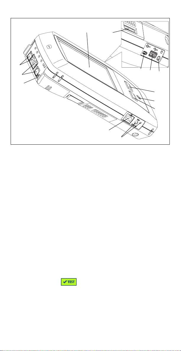
Connectors, Keys, and LEDs
Figure 1. Connectors, Keys, and LEDs
LCD display with touchscreen
Wired Ethernet Port B and Fiber Port B SFP receptacle–Port B
link and activity lights are located above. Port B is used for cable
test, packet capture and VoIP analysis.
Wired Ethernet Port A and Fiber Port A SFP receptacle–Port A
link and activity lights are located above. Connect the network
under test to Port A.
External Antenna Connector–Link and activity lights are above.
Management Port–For remote control of the analyzer, copying
files to or from the analyzer, browsing the web, SSH or telnet to
switches, etc.
Connector for the AC adapter–The LED is red when the battery
charges and green when the battery is fully charged.
–Press the HOME key to go to the home screen.
Power key. This key turns the tester On or Off.
–The AutoTest key starts a test. You can also tap the
AutoTest button on the display to start a test.
Headset jack
Type A USB port–Import and export files, install software
updates, connect a WebCam or video probe, or connect an
optional Wi-Fi adapter.
Micro-AB USB port–This connector is reserved for future use.
SD card slot–Capture files are stored on the SD card. You can
import or export Profiles and other files using the SD card.
Page 3
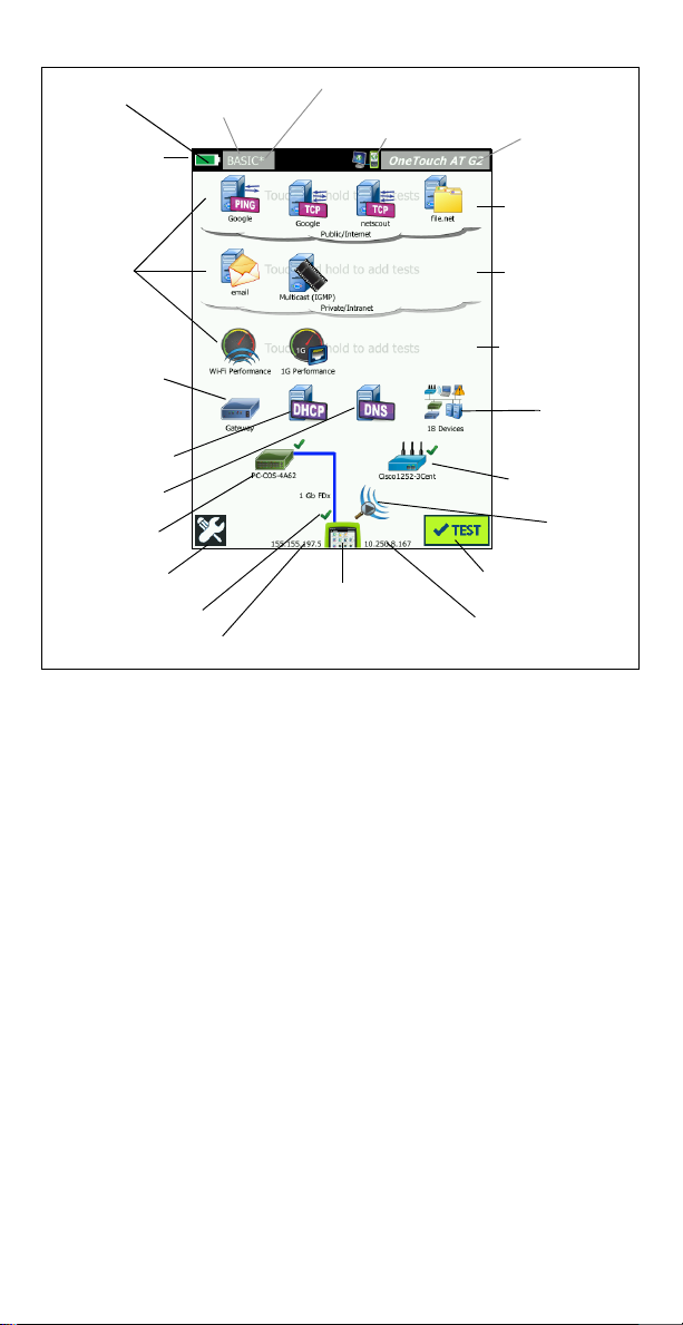
The HOME Screen
Remote Indicator
Asterisk indicates
changes not saved
Battery Icon
Profile Name
Shortcut Bar
Test
Tiers
Default
Gat ewa y
DHCP Server
DNS Server
Nearest
Switch
TOOLS button
Wired IP Address
Wi-Fi IP Address
AutoTest Button
Wi-Fi
Analysis
OneTouch AT G2
Access Point
Wired
Analysis
Local Network
Private Cloud
Public Cloud
Tap for
Reports and
Screenshots
Cable Test and PoE
Figure 2. The HOME Screen
The Shortcut Bar is located at the top of the display. When all tests
complete, the Shortcut Bar turns green if all tests passed, or red if
any test failed.
The Battery Icon turns red when the charge falls below 20%.
Tap t h e Profile Name to save, load, and manage test profiles.
An asterisk (*) indicates that the Profile contains changes that have
not been saved.
The Remote Indicator appears when a remote connection to the
OneTouch analyzer is established.
Tap t h e OneTouch AT G2 button to take a screen shot or to save
test results to a report.
The Tes t Tiers contain User Tests, which are custom tests that you
can create and modify.
Touch and hold white space on a test tier to add a new User Test.
Tap a User Test icon, and then tap the SETUP tab to configure the
test. Tap the
Touch and hold a User Test if you want to move, copy, or delete it.
Network infrastructure tests are located below the user tests.
Tap the Default Gateway icon to identify the IP and MAC addresses
of the current IPv4, IPv6, and Wi-Fi router, show routing protocols,
etc. Configure SNMP for the most complete results. Tap the TOOLS
RESULTS tab to see the test’s results.
Page 4

button , then tap Analysis.
Tap t h e DHCP Server to view the process and results of acquiring
an IP address via DHCP on both the wired and
Wi-Fi connections.
Tap the DNS Server button to view the performance of DNS servers
resolving the specified URL.
Tap t h e Wired Analysis icon to see wired devices discovered in the
broadcast domain. See “Wired Analysis” in this guide.
The Nearest Switch and Wi-Fi Network Connect tests are below the
network infrastructure tests.
Tap t h e Nearest Switch to show the switch name, model, port and
VLAN of the wired connection. If SNMP is enabled, additional
information is available.
Tap the Access Point icon for Wi-Fi Network Connect test results.
The target SSID and its security credentials must be included in the
loaded profile.
The media tests are next as you move down the screen.
Cable/Link/PoE provides
· cable test, if the analyzer cannot link
· link speed, duplex, receive pair, level, and polarity
· PoE class and type, unloaded voltage measurement, and
TruePower™ loaded voltage and power measurements
The Wi-Fi Analysis icon to see discovered devices in your wireless
network. See “Wi-Fi Analysis” in this guide.
The following icons are at the bottom of the screen.
TOOLS are discussed later in this document.
The Wired IP Address is shown to the left of the OneTouch AT G2
Instrument icon; the Wi-Fi IP address is to the right.
Tap t h e OneTouch AT G2 instrument icon at the bottom of the
screen for wired and Wi-Fi network connection details, errors,
statistics, and more.
The AutoTest button initiates link and runs infrastructure tests and
user tests.
How to Run an AutoTest
AutoTest provides a comprehensive test of network infrastructure
tests, along with user-defined tests.
The OneTouch G2 analyzer does not initiate any link, user test, or
infrastructure test activity until you run AutoTest.
1. Power the Analyzer
Connect the AC adapter to charge the battery if necessary.
2. Connect to the Network
Connect the network under test to Port A (Item in Figure 1). You
can use the RJ-45 Ethernet jack for copper cable, or an SFP inserted
in the SFP receptacle for fiber cable.
Page 5

3. Run AutoTest
Tap the AutoTest button (located at the lower-right corner of
the HOME screen), or press the AutoTest key (located on the front
. The OneTouch G2 analyzer will:
panel)
Link on active ports (wired and/or Wi-Fi ports)
Obtain IP addresses
Run Network Infrastructure Tests
Run User Tests - When multiple User Tests are present, they run
starting with the lower-left test on the bottom test tier and finishing
with the upper-right test on the top test tier.
4. View the Test Results.
To see a test’s detailed results,
tap its icon on the HOME screen.
The test’s SETUP or RESULTS tab
is displayed. Tap a tab to open it
The test’s status (pass or fail
) is indicated at the lower left
corner of the RESULTS tab.
When you tap the AutoTest key
or the AutoTest button again, all
test results are cleared and the
tests run again.
5. Create a Report
To create a comprehensive
network performance report:
1
Tap t h e OneTouch AT G2 button , which is in the
shortcut bar at the top of the HOME screen.
2Tap the Save Report button.
3 Change the file name if desired, then tap the DONE button.
You can also configure your OneTouch to automatically upload test
results to the Link-Live Cloud Service. See “How to Claim your
OneTouch AT to the Link-Live Cloud Service” on the next page.
To manage reports, tap the TOOLS button, then scroll down to the
File Tools section. Select the Reports button to open the report file
manager.
6. Add a User Test
Touch and hold white space on a test tier to add a new User Test.
Run AutoTest again to view the results.
7. Save a Profile
To save a Profile:
1
Configure the analyzer as desired (add User Tests, change
settings, etc.).
Page 6

2 Tap the Profile name, which is in the shortcut bar at the top of
the HOME screen.
3Tap the SAVE button.
4 To create a new profile, enter its name and tap the DONE
button. To use the existing name, tap the DONE button.
Load a Different Profile
To load a profile, tap the profile name at the top of the screen and
select the profile you want to load from the list.
How to Claim your OneTouch AT to the Link-Live Cloud Service
Link-Live Cloud Service is a free, online system for viewing, tracking,
and organizing your test results, which can be automatically
uploaded once you claim your device.
1
Create an account at Link-Live.com, or if you already have an
account, sign in.
If you are a new Link-Live user, the pop-up box will appear
automatically and prompt you to claim a device.
2 In the Link-Live Claim Unit pop-up bo x, select the OneTouch AT
image.
3 Follow the on-screen instructions to finish claiming.
Wired Analysis
During wired analysis, the OneTouch G2 discovers devices in the
broadcast domain or connected to APs in the broadcast domain, the
server specified in the DNS test, the servers specified in user tests,
and additional devices, through passive discovery.
When the analyzer is connected to a trunk port and is not configured
for a VLAN, all devices on the trunk are discovered. When the
analyzer is connected to a trunk port and is configured for a VLAN,
only devices in the same VLAN are discovered.
Devices are categorized and displayed on the WIRED ANALYSIS
screen. A summary view of hosts, access devices, and servers
provides an overview of devices on the network along with relevant
details such as IP address, MAC address, switch slot and port,
utilization, and problems.
Wi-Fi Analysis
The OneTouch AT G2 analyzer’s Wi-Fi analysis consists of discovery
and analysis of 802.11 networks, access points, clients, and channels
being used. It can also identify, classify, and locate non-802.11
interfering devices.
Tools are available for troubleshooting client connectivity. The
analyzer supports 802.11 a/b/g/n/ac technologies, operating in the
2.4-GHz and/or 5-GHz bands. Wi-Fi must be enabled for Wi-Fi
analysis to begin.
Page 7

How to configure the analyzer to link to a Wi-Fi network
1
On the HOME screen, tap TOOLS .
2Tap the Wi-Fi button.
3 Ensure that Enable Wi-Fi and Enable Connect are On.
4Tap the SSID button and select a network.
5Tap the Security button and enter the network’s credentials.
6 Run AutoTest.
The Wi-Fi Analysis icon on the Home screen changes to indicate
Wi-Fi link or scanning status.
Stopped - Tap the icon to initiate Wi-Fi analysis.
Linked and Testing
Linked but not testing - When AutoTest completes, the link is
maintained. Tap the icon to drop the Wi-Fi link, start Wi-Fi
scanning, and view the Wi-Fi ANALYSIS screen.
Scanning - The analyzer is performing Wi-Fi analysis
(scanning). Tap the icon to display the Wi-Fi ANALYSIS screen.
Tools
Tap the TOOLS button to access the following:
Setup Wizard–guides you in configuring your device profiles
Test Settings–wired and Wi-Fi connection settings
Cloud Tools–use to interact with the Link-Live Cloud Service:
AutoTest, Trending, Claim Unit, Unit Name, and Cloud Remote
Testing Tools–packet capture, VoIP Analysis, Wi-Fi network
validation, Performance Peer, web browser, Telnet/SSH, Toner,
Flash Port, and FiberInspector/WebCam
File Tools–use to manage profiles, AP authorization lists, reports,
and screen captures
Maintenance Tools–battery status, language, date and time, units,
display brightness, etc.
Page 8

Symbols, Certification and Compliance
Warning or Caution. Risk of damage or destruction to
equipment or software.
Warning: Risk of fire, electric shock, or personal injury.
Warning: Class 1 laser when an SFP module is installed. Do
not look directly into optical connectors. Risk of eye damage
from hazardous radiation.
Conformite Europeene. Conforms to the requirements of
the European Union and the European Free Trade
Association (EFTA).
Listed by the Canadian Standards Association.
This product complies with Australian standards.
Meets RoHS directive.
Do not put products containing circuit boards into the
garbage. Dispose of circuit board in accordance with local
regulations.
Do not connect the device to a telephone line or an ISDN
line.
Conforms to relevant South Korean EMC Standards.
Regulatory Statements
Este equipamento opera em caráter
Brazil
Regulatory Statement
Korea
Electromagnetic
Compatibility. Applies
to use in Korea only.
Class A Equipment
(Industrial
Broadcasting &
Communications
Equipment)
Mexico
Cofetel Notice
secundário, isto é, não tem direito a proteção
contra interferência prejudicial, mesmo de
estações do mesmo tipo, e não pode causar
interferência a sistemas operando em caráter
primário.
This product meets requirements for
industrial (Class A) electromagnetic wave
equipment and the seller or user should take
notice of it. This equipment is intended for use
in business environments and is not to be
used in homes.
La operación de este equipo está sujeta a las
siguientes dos condiciones: (1) es posible que
este equipo o dispositivo no cause
interferencia perjudicial y (2) este equipo o
dispositivo debe aceptar cualquier
interferencia, incluyendo la que pueda causar
su operación no deseada.
Page 9

低功率電波輻射性電機管理辦法
經型式認證合格之低功率射頻電機,非經許
Tai wa n
Regulatory
Compliance Warning
for Access Points
according to rule of
LP0002
可,公司、商號或使用者均不得擅自變更頻率、
加大功率或變更原設計之特性及功能。
低功率射頻電機之使用不得影響飛航安全及干擾
合法通信;經發現有干擾現象時,應立即停用,
並改善至無干擾時方得繼續使用。
前項合法通信,指依電信法規定作業之無線電通
信。
低功率射頻電機須忍受合法通信或工業、科學及
醫療用電波輻射性電機設備之干擾。
General Specifications
Battery Type: Rechargeable lithium ion battery pack
Temperature:
Operating: 32°F to 122°F (0°C to +50°C)
Charging: 0 C to +40 C
Storage: -40°F to 160°F (-40°C to +71°C)
Operating altitude: 13,123 ft (4,000 m) and 10,500 ft (3,200 m) with
AC adapter
Storage altitude: 39,370 ft (12,000 m)
Safety: IEC 61010-1: CAT None, Pollution Degree 2
EMC: IEC 61326-1: portable
Technical Specifications
You can find the Product’s technical specifications in the User
Manual, available online at enterprise.netscout.com.
Registration
Registering your product gives you access to valuable information
on product updates, troubleshooting tips, and other support
services. To register online, visit enterprise.netscout.com/
registration.
The Setup Wizard, which appears when you initially power on the
analyzer, guides you through registering the product and
configuring the analyzer’s settings and tests.
To check your Registration status, tap TOOLS , and under
Maintenance Tools, tap Product Registration.
Contact NETSCOUT
enterprise.netscout.com
customercare@netscout.com
Toll free: +1-844-833-3713
International: 978-320-2150
For more contact information, go to our website.
Page 10

LEGAL NOTIFICATION
Use of this product is subject to the End User License Agreement
available at
or which accompanies the product at the time of shipment or, if
applicable, the legal agreement executed by and between NETSCOUT
SYSTEMS, INC., and the purchaser of this product ("Agreement").
Government Use and Notice of Restricted Rights: In U.S. government
("Government") contracts or subcontracts, Customer will provide that
the Products and Documentation, including any technical data
(collectively "Materials"), sold or delivered pursuant to this Agreement
for Government use are commercial as defined in Federal Acquisition
Regulation ("FAR") 2.101and any supplement and further are provided
with RESTRICTED RIGHTS. All Materials were fully developed at private
expense. Use, duplication, release, modification, transfer, or disclosure
("Use") of the Materials is restricted by the terms of this Agreement and
further restricted in accordance with FAR 52.227-14 for civilian
Government agency purposes and 252.227-7015 of the Defense Federal
Acquisition Regulations Supplement ("DFARS") for military Government
agency purposes, or the similar acquisition regulations of other
applicable Government organizations, as applicable and amended. The
Use of Materials is restricted by the terms of this Agreement, and, in
accordance with DFARS Section 227.7202 and FAR Section 12.212, is
further restricted in accordance with the terms of NETSCOUT's
commercial End User License Agreement. All other Use is prohibited,
except as described herein.
This Product may contain third-party technology. NETSCOUT may license
such third-party technology and documentation ("Third-Party Materials")
for use with the Product only. In the event the Product contains ThirdParty Materials, or in the event you have the option to use the Product in
conjunction with Third-Party Materials (as identified by NETSCOUT in the
applicable Documentation), then such third-party materials are provided
or accessible subject to the applicable third-party terms and conditions
contained in the "Read Me" or "About" file located on the Application CD
for this Product. To the extent the Product includes Third-Party Materials
licensed to NETSCOUT by third parties, those third parties are third-party
beneficiaries of, and may enforce, the applicable provisions of such
third-party terms and conditions.
Open-Source Software Acknowledgment: This product may incorporate
open-source components that are governed by the GNU General Public
License ("GPL") or licenses that are compatible with the GPL license ("GPL
Compatible License"). In accordance with the terms of the GNU GPL,
NETSCOUT will make available a complete, machine-readable copy of the
source code components of this product covered by the GPL or
applicable GPL Compatible License, if any, upon receipt of a written
request. Please identify the product and send a request to:
NETSCOUT SYSTEMS, INC. reserves the right, at its sole discretion, to
make changes at any time in its technical information, specifications,
service, and support programs.
http://www.netscout.com/legal/terms-and-conditions/
NETSCOUT SYSTEMS, INC.
GNU GPL Source Code Request
310 Littleton Road
Westford, MA 01886
Attn: Legal Department
Rev. 02/04/2016
 Loading...