

Page 1

NETSCOUT SYSTEMS, Inc.
LinkRunner™ G2
User Guide
October 30, 2017
Page 2

Legal Notification
Use of th is product is subject to t he En d User License
Agreement available at h tt p://ent erprise.netscout.com/EULA
or w hich accompanies the product at the tim e ofshi pment or,
if applicable, th e legal agreement executed by an d betw een
NETSCO UT SYSTEMS, IN C., an d the purchaser of this product
("Agreement ").
Government Use and N otice of Restricted R ight s: In U.S.
government ("Government") contracts or subcont racts,
Customer will provide that the Products and Document ation,
includin g any techn ical data (collectively "M aterials"), sold or
delivered pursuant to t his Agreement for Governmen t use are
commercial as defined in Federal Acquisition Regu lati on
("FAR ") 2.101 and any supplement and furth er are provided
with RESTRIC TED R IGHTS. All M aterials were fully developed
at private expense. Use, duplication, release, modification,
transfer, or disclosure ("Use") of the Mat erials i s restricted by
the terms of this Agreement and furt her restricted in
accordance with FAR 52.227-14 for civilian Governmen t agency
purposes and 252.227-7015 of th e Defense Federal Acquisition
Regul ations Supplement ("DFAR S") for military Governmen t
agency purposes, or the similar acquisition regulati ons of
other applicable Governmen t organizations, as applicable and
amended. Th e Use ofM aterials is restricted by t he t erms of
this A greement, and, in accordance with DFARS Section
227.7202 and F AR Section 12.212, is furth er restricted in
accordance with the terms of N ETSCOUT's commercial End
User License A greement. All other Use is prohibited, except as
described h erein.
This Product may contain t hird-party technology. NETSC OUT
may license such t hird-party techn ology an d document ation
2
Page 3

("Third-Party Materials") for use with t he Product onl y. In t he
event t he Product contain s Third-Party M aterials, or i n th e
event y ou have the option to use t he Product in conju nction
with Third-Party M aterials (as identi fied by NETSCOUT in t he
applicable Documentat ion), th en such th ird-party mat erials
are provided or accessible subject to the applicable third-party
terms and conditions contained in th e "Read Me" or "A bout"
file l ocated on the Application CD for thi s Product. To th e
extent the Product in cludes Third-Party Materials licensedt o
NETSCO UT by th ird parties, t hose t hird parties are th ird-party
beneficiaries of, and may enforce, th e applicable provisions of
such thi rd-party terms and condition s.
Open-Source Software Acknowledgment: Th is product may
incorporate open-source component s t hat are governed by t he
GNU General Public License ("GPL") or li censest hat are
compatible with the GPL license ("GPL C ompatible Li cense"). In
accordance with the terms of t he GNU GPL, N ETSCOUT will
make available a complete, machine-readable copy of th e
source code componen ts of this product covered by th e GPL or
applicable GPL Compatible License, if any, u pon receipt ofa
writt en request. Please identify the product and send a
request t o:
NETSCO UT SYSTEMS, In c.
GNU GPL Source C ode Request
310 Lit tlet on Road
Westford, MA 01886
Att n: Legal Department
NETSCO UT SYSTEMS, IN C. reserves t he righ t, at i ts sole
discretion, to make changes at any t ime in it s t echnical
information, specifications, service, and support programs.
3
Page 4

Contents
Contact Us 7
Introduction 8
About this Guide 9
Most Commonly Used Features 11
Safety 12
Physical Features 14
Buttons and Ports 15
Power and Charging 18
Maintenance 20
Home Screen and Android Interface 21
Home Screen 22
Swiping and Navigation 26
Top Notification Panel 27
Quick Settings Panel 29
Device Settings 30
Sharing 31
LinkRunner G2 Application Settings 33
4
Page 5

Left-Side Navigation Drawer 34
Configuring TestSettings 35
Profiles and Jobs 41
LinkRunner G2 Tests and Results 44
AutoTest 45
Floating Action Button 59
Switch Test 60
Cable Test 62
Link-Live Cloud Service 67
Getting Started in Link-Live 68
Software Management 70
Managing Files 71
Updating Firmware 75
Restoring Factory Defaults 77
Changing the Language 78
Additional Features 79
Reflector 80
Camera and Flashlight 83
5
Page 6

Wi-Fi Bluetooth USB Adapter 84
Specifications and Compliance 87
Specifications and Compliance 88
6
Page 7

Contact Us
Online: http://enterprise.netscout.com
Email: CustomerCare@netscout.com
Phone: 1-844-833-3713
For more phone numbers, go to our website
enterprise.netscout.com/contact.
NETSCOUT SYSTEMS,I nc.
310Littleton Road
Westford, MA 01886
www.NETSCOUT.com
Register your LinkRunner G2
Registering your product with NETSCOUT gives
you access to valuable information on product
updates, troubleshooting procedures, and other
services.
To register, fill out the online form on the
NETSCOUT websiteat
http://enterprise.netscout.com/register.
7
Page 8

LinkRunner G2 User Guide
Introduction
The LinkRunner G2 is
an Android-based
network testing and
troubleshooting tool. It
allows networking
professionals to easily
verify network
connectivity and
validate cabling.
LinkRunner G2 can also
act as a packet reflector
for performance tests
run by other NETSCOUT
testers.
8
Page 9
Introd uction
About this Guide
This User Guide covers all the LinkRunner G2
(LR G2) testing functionality and basicelementsof
the Android interface.This guide is meant for
users knowledgeable about networking testing
operations.
For additional help with your LR G2, visit
Link-Live.com, and create an account. I n Link-Live,
selectthe navigation menu icon atthe top left
of the page to open the navigation drawer, and
click .
If you already have a Link-Live Cloud Service
account, yo u can go directly to
Link-Live.com/Questions for Knowledge Base
articlesand Frequently Asked Questions.
PDF Reader Application
A PDF reader application is pre-installed on your
LinkRunner G2 device for the purpose of viewing
this guide. With it, you can navigate through the
pages,touch headings in the Contents list and
blue linksto skip to specific sections or open
9
Page 10

Introd uction
external websites, and use the search feature to
find specificterms.
10
Page 11

Introd uction
Most Commonly Used Features
Touch the links below to skip to the instructions
for the features listed:
"AutoTest" on page45
"Cable Test" on page62
"Switch Test" on page60
"Configuring Test Settings" on page35
"Home Screen" on page22
"Reflector" on page80
"Wi-Fi Bluetooth USB Adapter" on page84
11
Page 12

Introd uction
Safety
Observe the following safety information:
Use only the AC Adapter prov ided or Po wer over
Ethernet to charge the battery.
Use the proper terminalsand cable for all
connections.
To avoid possible electric shock or personal injury,
follow these guidelines:
l Do not use the product if it is damaged.
Before using the product, inspect the case,
and look for cracked or missing plastic.
l Do not o perate the product around explos-
ive gas, vapor, or dust,
l There are no serviceableparts. Do not try to
service the product.
l If this pro duct isused in a manner not spe-
cified by the manufacturer, the protection
prov ided by the product may be impaired.
12
Page 13

Safety Symbols
Warning or Cauti on: Risk of
W
damage to or destructi on of
equipment or software.
X
Warning: Risk of electrical s hock.
Certified by UL North America
Safety Standards.
Not for co nnection to a public
j
telephone system.
Class 1 Laser Product. Do not
*
look into the laser.
Introd uction
13
Page 14
LinkRunner G2 User Guide
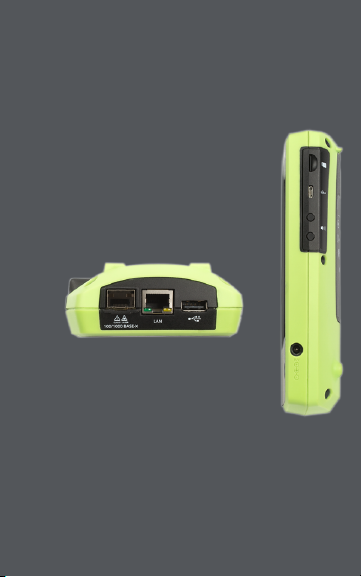
Physical Features
This User Guide section
illustrates the ports and buttons
on the LinkRunner G2 and
describes charging and
maintenance.
14
Page 15
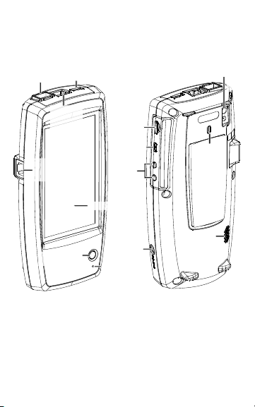
Touchscreen
USB Port
100/1000 BASE-X
Fiber Port
RJ-45 LAN
Port and
Trasmit
LEDs
RJ-45 Cable Test/
Wire Mapping
(WMAP) Port
Micro-USB
On-the-go
Port
Micro-SD
Card Slot
Charging
Port
Kensington
Lock
Camera
and
Flash
Volume
Buttons
Microphone
Speaker
Power Button
and LED
Physical Features
Buttons and Ports
Button and port functions are described below.
Figure 1 : LinkR unner G2 Physical Features
15
Page 16

Feature Description
100/1000 BASE-X
Fiber Port
USB Port
RJ-45 LAN Port
(10/100/1000
BASE-T)
Transmit LEDs
Cable Test/ Wire
Mapping Input
(WMAP)
Power Button
and LED
Charging Port
Mic rophone
Camera and
Flash
Mic ro SD Card
Slot
Connects to an SFP adapter and
fiber cable
Connects to any USB device
Connects to the network using
an Ethernet cable
Charges the unit if PoE is
available
Green LED lit: Linked
Yellow LED flashing: Activity
Used for patch cable testing
Glows gr een when the unit is
powered on
Glows red w hen the unit is
charging
Connects to AC adapter for
charging
Allows voice input
Captures images and acts as a
flashlight
Used for removable storage
expansion
16
Physical Features
Page 17

Feature Description
Mic ro USB Onthe-Go Port
Kensington
Lock
Volume Butt ons
Speaker
Connects to a USB On-the-Go
cord for communicating with a
PC or USB peripheral
Allows you to lock your unit
Increase or decrease the audio
volume
Produces audio
17
Physical Features
Page 18

Physical Features
Power and Charging
The LinkRunner G2 containsa rechargeable
Lithium Ion battery. You can charge your LR G2
using either AC or Power over Ethernet (PoE). The
LinkRunner G2 does not charge via the USB port.
See Buttons and Ports.
Charging
To charge with AC power, plug the included AC
adapter into an AC outlet,and connect it to the
charging port on the device.
To charge with PoE, connect the RJ-45 port on the
device to a network switch with PoE availableor
with a PoE injector.
NOTE:The LR G2 must be powered on or in sleep
mode to charge via PoE.
Charge the battery for 4-6 hours before first use.
Powering On
l Press the power button on the front of the
unit to power on the LinkRunner G2.
l When the unit ison, press the power button
to put it in sleep mode.
18
Page 19

Physical Features
l To shut down, hold the power button for
one second until the Power off dialog box
appears on the touchscreen, then tap
Power off .
l To perform a hard power off (without shut-
ting do wn the software), pressand hold the
power button for five seconds.
The first time you turn iton, the LinkRunner G2
testing application opens and begins testing your
network immediately. Connect the top RJ-45LAN
port or 100/1000 BASE-X Fiber port to an active
network to begin receiving test results.
19
Page 20

Physical Features
Maintenance
To clean the d isplay, use a lens cleaner and a soft,
link-free cloth.
To clean the case, use a soft cloth that ismoist with
water or a weak soap.
WCAUTION: Do not use solvents or abrasive
materials that may damage the product.
20
Page 21

LinkRunner G2 User Guide
Home Screen and Android Interface
This section explains how to use the
features of the Android home screen and
user interface to navigate and organize
your device.
The LinkRunner G2 interface applies
many of the operations typical of any
Android device. Use swiping touchscreen
motions to navigate through screens and
to drag down the top notification panel.
21
Page 22

Home Screen
Tap this icon
to view the
User Guide.
Ta
This is the
Notification
Bar.
Swipe down
from the
top of the
screen to
open the
Top
Notification
Panel.
These are
the default
Home
Screen apps.
Touch to
open.
NETSCOUT
App Store
Device
Settings
APPS
Screen
Web
Browser
File
Manager
This is the
Home Screen.
Swipe left and
right to move
through
pages.
Go to the
APPS Screen
to add app
shortcuts to
your Home
Screen.
Returns to
the previous
screen.
Tap to view and
close all open
applications.
Returns
to the
Home
Screen.
Opens the
LinkRunner
G2 testing
application.
Figure 2 : Home Screen
Home Screen and And roid Int erface
22
Page 23
Home Screen and And roid Int erface
Notification Bar
The Notification Bar across the top of the screen
displaysnotification icons from the Android
system as well as the following LinkRunner G2
specificicons:
indicates access to Power over Ethernet for
power and charging.
indicates that a wired Ethernet connection is
established.
Touch and swipe down on the Notification Bar to
open the Top Notification Panel.
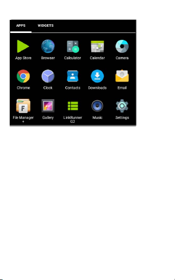
APPS Screen
Touch the APPS button on the Home Screen
to open the APPS screen.
23
Page 24
Home Screen and And roid Int erface
Figure 3 : APP S Screen
Swipe left or touch WIDGETS to view the WIDGETS
screen.
Touch and hold (long press) an application's icon
or a widgetto add it to the Home Screen.
Open the NETSCOUT App Store to download
Andro id applications specifically chosen to work
with the LinkRunner G2 tester.
24
Page 25
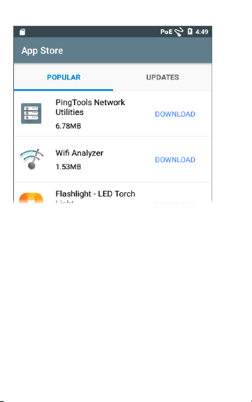
Figure 4 : App Sto re
Home Screen and And roid Int erface
25
Page 26

Home Screen and And roid Int erface
Swiping and Navigation
The navigation actions you can perform to mo ve
through screens and panels in LinkRunner G2 are
the same as those you would use to navigatean
Andro id phone or tablet.
Swiping
Touch and drag your finger or "swipe" up, down,
left, and right to move through pagesof the
Home Screen and LinkRunner G2 testing
application, scroll up or down in long screens, and
pull out navigation drawers and panels.
Long Pressing
Touch and hold or "long press" files o r application
icons to reveal additional operations. For
example, you can long press a file name in the File
Manager Application to show options for moving
or sharing the file.
26
Page 27
Home Screen and And roid Int erface
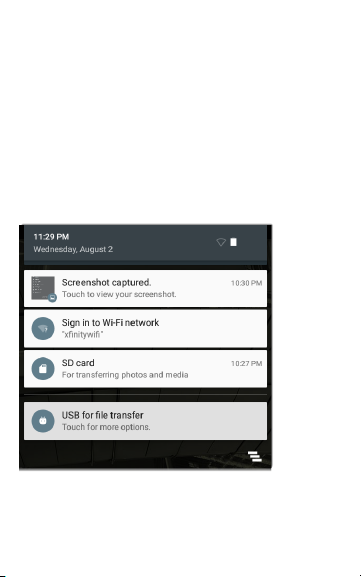
Top Notification Panel
The Top Notification Panel containsnotifications
from yo ur device, such as downloaded and
installed applications,inserted hardware,
captured, screenshots,and availableupdates.
Swipe (touch and drag) down from the very top
of LinkRunner G2 screen to slide down the
notification panel.
Figure 5 : Top No tification Panel
l Touch a notification to open the related app,
image,device options, or perform other
27
Page 28

Home Screen and And roid Int erface
actions.
l Swipe left on a notification to dismissit.
l
Touch the icon at the lower right of the
panel to dismiss all notifications.
28
Page 29

Home Screen and And roid Int erface
Quick Settings Panel
The Quick Settings Panel is also accessed by
swiping down from the top of the screen. You can
either swipe down twice, or touch the dark grey
top portion of the navigation panel to open it.
Figure 6 : Quick Settings Panel
Touch an icon in the panel to enable or disable the
corresponding feature. See Wi-Fi Bluetooth USB
Adapter for more information on using the
optional Wi-Fi and Bluetooth adapter accessory.
29
Page 30

Home Screen and And roid Int erface
Device Settings
To accessthe Android device settings, touch the
Settings icon on the Home Screen.
Figure 7 : And roid Device Settings
Use the device Settingsscreen to adjust the
LinkRunner G2 display, sound, date/time, and
language,view installed applications and memory
devices, update your software, or resetto factory
defaults.
30
Page 31

Home Screen and And roid Int erface
Sharing
LinkRunner G2 allows you to "share" images and
files like y ou would on a cellular phone. When you
seethe Share icon touch it to view your
configured sharing options.
This
example
shows a
captured
screenshot
notification.
SHARE opens the Share with pop-up dialog,
where you can chose a sharing method.
NOTE:Touch the
LinkRunner G2
option to share to
Link-Live Cloud
Serviceor to save to
your imagesgallery on the LinkRunner G2.
31
Touching
Page 32

Home Screen and And roid Int erface
Capturing a Screenshot
On the LinkRunner G2, pressand hold the Power
button and the Volume Down button at the same
time for one second to capture a screenshot. The
LinkRunner G2 emitsa beep and displays the
captured screenshot notification when it is
successful.
32
Page 33

LinkRunner G2 User Guide
LinkRunner G2 Application Settings
This chapter
describes the
processes for
configuring test
settings and
saving them to a
profile.
33
Page 34

Once claimed to
Link-Live, the
unit’s name and
organization
shown here.
Tap here to open
the Profiles
screen.
Tap here to open
the Settings
screen.
Tap here to enter
a new Job
comment.
Tap here to use
the Reflector
feature.
Tap here to view
information about
your unit.
LinkRu nner G2 Application Settin gs
Left-Side Navigation Drawer
To accessthe LinkRunner G2 testing application
settings,touch the navigation menu icon atthe
top leftof the LinkRunner G2 application screen.
34
Figure 8 : Left-Side Navigation D rawer Opt ions
Page 35
LinkRu nner G2 Application Settin gs
Configuring Test Settings
The LinkRunner G2 settingsallow you to
customizetest settingsfor PoE, Speed/Duplex,
Security, IP configuration, test targets, and other
aspects of AutoTest, Switch Test, and Cable Test.
To configure testing for your network, touch the
navigation menu icon at the top leftof the
LinkRunner G2 application screen, and then touch
the option.
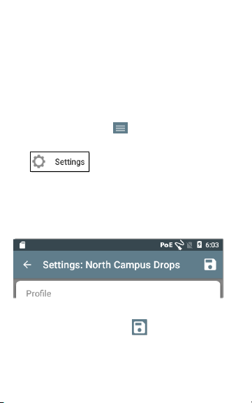
Saving and Loading Profile Settings
The header o n the Settings screen displays the
name of the current Profile.
To save yo ur settings to a Profile (and v iew other
options), tap the save icon at the top right of
the Settings screen.
35
Page 36

LinkRu nner G2 Application Settin gs
To keep your revised settings without saving them
to a profile, touch the back arrow icon to the left of
the Settings screen header. Your new settings are
applied, and an asterisk * isadded to the profile
name to indicate unsaved changes.
See Profilesand Jobs for more on profiles.
PoE
Enable PoE: Slide the toggle switch right to enable
the P oE testportion of AutoTest,and slide leftto
disableit.
Enable TruePower™: Slide the toggle switch right
to enable the TruePower feature. TruePower
validates that the Switch (PSE) and cabling can
prov ide the requested power under load.
Class: Touch the down caret to the right of the
field to select a PoE class setting to match your
switch's(or P oE injector's) availableclass.The
LinkRunner G2 supports Cisco's UPOE, which can
prov ide up to 51W. (Note that your switch may
advertisea wattage higher than 51W, but because
of lossover the cable, the LR G2 does not receive
the total wattage provided by the switch.)
36
Page 37

LinkRu nner G2 Application Settin gs
Connect
Speed/Duplex: Select the speed and duplex
option that you want to test your network against.
The defaultis Auto negotiation.
Security
802.1X Authentication: Slide the toggle switch
right to enable 802.1Xauthentication.
EAP Type: This field appears if 802.1X
authentication isenabled. Touch the do wn arrow
to choose the correct type. Additional security
fields, such as Username and Password, display as
required.
IP
IPv6: Slide the toggle switch right to enable IP v6.
IP Configuration: Touch the down caret to
switch between DHCP and StaticIP configuration.
If you choose static, the IP Address,Subnet Mask,
and other IP fields display. Touch each field to
open a pop-up number pad and enter the
addressesas needed. Touch OK to save them.
Proxy: Slide the toggle switch right to enable
Proxy settings.When proxy is enabled, the
37
Page 38

LinkRu nner G2 Application Settin gs
Address, Port, Username, and Password fields
appear. Touch each field to open a pop-up
keyboard and enter the appropriate data.Touch
OK to save your entries.
Targets
You can add an unlimited number of test targets
by entering the IP address or a URL and specifying
either an ICMP Ping or TCP Port Open test for
each target.
Address: When AutoTest runs, the LinkRunner
G2 attempts to reach the target address entered in
this field.The defaultis Google.com.
l Touch the Address field to open a pop-up
keyboard and enter a new address.
l Touch the action overflow icon to the right
of the Address field to either Delete the target addressfield from AutoTestor Duplic -
ate the current targetaddress entry.
Port: Thisis the port the LinkRunner G2 usesto
connect to the targetaddress for a TCP Port Open
test. The default is 80. Touch the Port field to open
a pop-up number pad and enter a new port
number. Touch OK to save it.
38
Page 39

LinkRu nner G2 Application Settin gs
Ping: Slide the toggle switch right to run an ICMP
Ping test to the target addresstest. The Port field
disappears when this toggle is enabled.
+ ADD TARGET: Touch to add additional target
address fields.
VLAN
Enable VLAN: Slide the toggle to the right to
enable VLAN settings.Once enabled, VLAN ID and
VLAN Priority fields appear. Touch these fields to
open a pop-up number pad and enter the correct
ID and priority. Touch OK to save them.
User Defined MAC
Enable User Defined MAC: Slide the toggleto the
right to enable a user-defined MAC address.When
enabled, the User Defined MAC field turns from
grey to black.
User Defined MAC: If enabled, touch thisfield to
open a pop-up keyboard and enter your MAC
address.Touch OK to save it.
General Settings
Cable Unit: Touch the do wn caret to select
either meters or feet for the Cable Test unit of
39
Page 40

LinkRu nner G2 Application Settin gs
measurement.
Default Settings: Tap this field to restore the
LinkRunner G2 testing application to factory
default pro file settings.A dialog box willask you to
confirm Yesor No before it restores.
NOTE:See Restoring Factory Defaults for
instructions on resetting your entire LR G2 device
to factory defaultconfiguration.
40
Page 41

LinkRu nner G2 Application Settin gs
Profiles and Jobs
A Profile is a saved configuration of testsettings.
The currently active Profile'sname is displayed in
the Left-Side Navigation Drawer and at the top of
the Settings screen,as shown below.
The header o n the Settings screen displays the
name of the current Profile.
An asterisk * next to the Profile name indicates
that yo u have adjusted settingssince the Profile
waslastsaved.
To save yo ur settings to a Profile (and v iew other
options), tap the save icon at the top right o f
the Settings screen.
Profilesaving options include the following:
l Save savesthe current settingsto the cur-
rently loaded profile.
41
Page 42

LinkRu nner G2 Application Settin gs
l Save As savesa new Profile with the current
settings and opens a po p-up keyboard for
entering a new name. Touch SAVE to save
the new Profile Name.
l Load o pens the Profiles screen.
Profiles Screen
This screen displays a listof allthe saved Profiles.
NOTE:The "Link-Live" profile is a profilecreated
from Link-Live Cloud Service and downloaded to
LinkRunner G2. A single pro file can be created in
Link-Live and pushed to many LinkRunner G2s.
Touch a Profile'sname to load itssaved settings.
Touch the overflow action icon next to a Profile
name to Delete, Rename, or Duplicate it.
If you choose to duplicate a Profile, a pop-up
dialog prompts you for a New P rofile Name.
Touch SAVE to save the new name.
42
Page 43

LinkRu nner G2 Application Settin gs
Jobs
Jobs are comments that are added to the test
resultsuploaded to Link-Live Cloud Service. They
help you organize testresults.
To save a Job comment, touch the navigation
menu icon at the top lefto f the LinkRunner G2
application screen, and then touch the Job field to
open a dialog box and the pop-up keyboard.
Touch OK to save the new Job comment.
If the Job saved on y our LinkRunner G2 unit
matchesa named folder in your Link-Live
organization, the test
resultsare automatically
sorted into that folder.
If you want to createa
new folder in Link-Live
and save your test
resultsto it, simply add a forward slash / at the
beginning of the Job name, as shown in the image
on this page.
43
Page 44

LinkRunner G2 User Guide
LinkRunner G2 Tests and Results
The LinkRunner
G2 features a
main AutoTest
screen, a Switch
Test screen, and a
Cable Test screen.
Swipe left and
right to move
through the three
test screens.
This User Guide
chapter describes
each test section
and its results.
44
Page 45

LinkRu nner G2 Tests and R esults
AutoTest
To run AutoTest, connect the RJ-45port or the
Fiber port on the top of the LinkRunner G2 to an
active network switch.Touch the NETSCOUT logo
icon at the bottom of the screen to open the
LinkRunner G2 testing application.
Each individual test is presented on its own card.
Tap the do wn caret on the right side of a card
to expand and view detailed results.
The AutoTesttab
header shows the
number of failed
tests (if any) in red
and the number
of warnings in
yellow.In the
image on this
page, the PoE,
DHCP, and LinkLive upload tests
have failed. The
test icons also turn green, yellow, or red based on
the test results.
45
Page 46

LinkRu nner G2 Tests and R esults
To restart testing at any time, tap the refresh icon
at the top right of the LR G2 app screen.
TestSettings are described in the LinkRunner G2
Application Settings chapter.
The following subsections describe each card in
the AutoTest.
46
Page 47

LinkRu nner G2 Tests and R esults
Power over Ethernet (PoE) Test
The header o f the P oE Testcard displays the
measured Voltage, Class, and Wattage.
Figure 9 : PoE Test Card Expanded
The PoE card displays additional TruePower™
resultsonly if TruePower is enabled in the
PoE Settings. TruePower appliesa load equivalent
to the selected classto mimic a Powered Device
(PD).
47
Page 48

LinkRu nner G2 Tests and R esults
Detailed PoE Results
PoE Result Description
Requested Class
Received Cl ass
TruePower™
Power
Unloaded Voltage
TruePower™
Voltage
PSE Type
Positi ve
Negative
Class selected in the PoE test
settings
Class acknowledgment
received bythe LRG2 from the
switch
Measured wattage with load
Measured voltage without
load
Measured voltage with load
Switch's advertised Power
Sourcing Equipment ( PSE)
type; If type cannot be
determined, displays 1/2.
Positive PoE cable pair IDs
Negative PoE cable pair IDs
48
Page 49

LinkRu nner G2 Tests and R esults
Link Test
The Link Test card header displays the advertised
speed and duplex in grey and the detected speed
and duplex in black text.
Figure 1 0: Lin k Test Card Expanded
Detailed Link Results
Link Result Description
Advertised Speed
Actual Speed
Advertised
Duplex
Speed capability as reported
by the switch
Link speed as measured by
LinkRunner G2
Duplex capabilities reported
by the switch
49
Page 50

LinkRu nner G2 Tests and R esults
Link Result Description
Actual Duplex
Rx Pair
Polarity
Interface
Duplex in use as detected by
LR G2
Link receive pair
Link polarity: normal or
reversed
Link interface: Copper/RJ-45
port or SFP/Fiber port
50
Page 51

LinkRu nner G2 Tests and R esults
Switch Test
The Switch Test card header displays the
discovered switch name or simply Ethernet if no
switch name could be discovered.
Figure 1 1: Swit ch Test Card Expanded
If LinkRunner G2 wasunable to obtain switch
information from the first AutoTestrun, touch
REFRESH to capture and display the next port
advertisement/xDP (LLDP or CDP).
Detailed Switch Results
Switch Result Description
Port
VLAN
Discovered port name
Discovered VLAN ID number
51
Page 52

LinkRu nner G2 Tests and R esults
Switch Result Description
Voice VLAN
Name
Model
Address
Type
Discovered Voice VLAN ID
number
Discovered switch's name
Discovered switch's model
Discovered switch's IP address
Switch type: CDP or LLDP
52
Page 53

LinkRu nner G2 Tests and R esults
DHCP Test
The DHCP Test card header displaysthe DHCP
server's IP address.
Figure 1 2: D HCP Test Card Expanded
Detailed DHCP Results
DHCP Result Description
Discover
Offer ti me
Status of the discovery frame
broadcast fr om LRG2
Time between when LR G2
sent the discovery and
received an address offer
from the DHCP server
53
Page 54

LinkRu nner G2 Tests and R esults
DHCP Result Description
Request
ACK Time
Server
Subnet
Lease Time
Status of the address request
sent fr om LRG2
Time between LRG2 sending
the r equest and receiving the
acknowledgement from the
DHCP Server
IP address of the DHCP server
IP address of the subnet
where LR G2 is testing
Time the IP address is leased
to the LR G2 by the DHCP
server
54
Page 55

LinkRu nner G2 Tests and R esults
DNS Test
The DNS test card header displays the DNS IP
addresses.
Figure 1 3: D NS Test Card Expanded
Expand the DNS card to view the response times
from each DNS server. The LR G2 pings each DNS
server three times and displays the response time
from each Ping. Up to four DNS servers are
captured and displayed on the DNS test card.
55
Page 56

LinkRu nner G2 Tests and R esults
Gateway Test
The Gateway Testcard d isplaysthe gateway's IP
address.
Figure 1 4: Gateway Test Card Expanded
The LR G2 p ings the gateway three timesand
displaysthe response time from each P ing.
56
Page 57

LinkRu nner G2 Tests and R esults
Target Tests
The Targets Testsare user-assignableendpoints
that LR G2 attempts to connect to each time
AutoTest runs. Target testsare either P ing or TCP
Port Open tests.
See Targets in the Configuring TestSettings
chapter.
The TargetTestcard header shows the URL or IP
address of the target and the port number if
applicable.
Figure 1 5: Target Test Cards
57
Page 58

LinkRu nner G2 Tests and R esults
The expanded Target Test card shows the IP
address of the target,the type of test (Ping or
TCP), and the time for each response received by
LR G2.
Touch CONTINUOUS to run a continuous
monitoring test to the target.A dialog box appears
and displays the continuous Ping or TCP Port
Open test results until you close the dialog bo x.
Link-Live Upload
The Link-Live Test card indicateswhether the
LinkRunner G2 wasable to upload your test
resultsto the Link-Live Cloud Service. Refer to the
chapter on Link-Live Cloud Service for more
information.
58
Page 59

LinkRu nner G2 Tests and R esults
Floating Action Button
The Floating Action Button or FAB appears on
many of the Android and LinkRunner G2
application screens. It offers additional actions
related to the current screen or test.
For example, the
AutoTest FAB allows
you to add a picture o r
a comment to the last
AutoTest results.
Tap or click the FAB
once to view the
additional options
available. Then, touch
the pop-up button for the action you want to
perform.
59
Page 60

Switch Name
and Model
Switch IP address
Port and slot number
Port VLAN IDs
Switch Test FAB
Sw
Speed and Duplex:
Advertised/Detected
Sp
Ad
PoE Voltage and
Wattage:
Advertised/Detected
PoE Positive and
Negative cable pairs
Blue line for Copper/LAN
Orange line for Fiber/SFP
LinkRu nner G2 Tests and R esults
Switch Test
The Switch test tab displays the information from
the nearestswitch by locating the port
advertisement (xDP) on the first few packets seen
by LinkRunner G2.
Figure 1 6: Swit ch Test Screen
60
Page 61

LinkRu nner G2 Tests and R esults
Tap the FAB on the Switch
test screen to access the
following actions:
Refresh xDP: Captures and
displaysthe next port
advertisement (CDP or
LLDP).
Flash Port: Causesthe
switch to flash the LED on the port where the
LinkRunner G2 isconnected. Touch and drag the
slider between Slow and Fast to differentiate it
from the other switch port LED flash rates.
To restart testing at any time, tap the refresh icon
at the top right of the LR G2 app screen.
61
Page 62

LinkRu nner G2 Tests and R esults
Cable Test
The Cable testcan help you determine cable
length and status, wire map patch and structured
cabling, and locatecables.
The Cable testtab can perform testsusing the four
options described in this section.
To restart testing at any time, tap the refresh icon
at the top right of the LR G2 app screen.
Refer to Buttons and Ports as needed.
62
Page 63

LinkRu nner G2 Tests and R esults
Open Cable TDR Testing
Connectan open cable (unterminated) into the
top RJ-45 port to measure its length and view any
shorts, opens, or splits.
Figure 1 7: Open/ Unterminated Cable Test
63
Page 64

LinkRu nner G2 Tests and R esults
Patch Cable Testing
Connecta cablefrom the top LinkRunner G2 RJ-45
LAN port into the side RJ-45 Cable Test/Wire
Mapping P ort to view its length and wire m apping,
including any faults.
Figure 1 8: RJ-45 LAN Po rt to RJ-45 Cable Test Po rt
64
Page 65

LinkRu nner G2 Tests and R esults
Wire Mapping
Connectthe top RJ-45port to a cable terminated
with an external WireView Cable ID accessory. A
WireView #1 is included with your LinkRunner G2.
Additional W ireViews2-6 are availablefor
purchase.
Figure 1 9: Wire Mapper Cable Test
The Wire Mapper Cable Testdisplaysthe number
of the W ireView attached, unless a cablefault
prevents LR G2 from detecting the WireView.
A cable/drop port can be traced using a WireView
up to 300 ft/100 m from the LinkRunner G2.
65
Page 66

LinkRu nner G2 Tests and R esults
Using the Tone Function
A cablecan also be traced using a Fluke Networks*
IntelliTone™ Probe, or any analog probe, and the
Tone function.
Connecta cableinto the
top RJ-45 port, touch the
FAB, and selectthe
appropriate Tone o ption
for your probe. The
LinkRunner G2 emitsthe
tone through the cable,
and the probe detects it,
allowing you to trace the
wire or locate it in the switch closet.
* IntelliTone is a trademark of Fluke Networks.
66
Page 67

LinkRunner G2 User Guide
Link-Live Cloud Service
Link-Live
Cloud Service
is a free,
online system
for collecting,
tracking,
organizing,
and reporting your test results, which are
automatically uploaded once your
LinkRunner G2 is claimed.
Claiming your LR G2 to Link-Live also
allows you to update the firmware on your
unit and access applications in the
NETSCOUT App Store that have been
specifically chosen to work with
LinkRunner G2.
67
Page 68

Link-Live Cloud Service
Getting Started in Link-Live
To start, create a user account at Link-Live.com,
and sign in.
On the LinkRunner G2 Unit
In the LinkRunner G2 testing application on your
LR G2 unit, touch the navigation menu icon at
the top left of the screen, and touch CLAIMNOW
in the navigation drawer.
In Link-Live
The first time you sign in to Link-Live, a pop-up
window appears prompting you to claim a device.
If you already have a user account and other
devicesclaimed to Link-Live, navigateto the Units
page fro m the leftside navigation drawer, and
68
Page 69

Link-Live Cloud Service
click the Claim Unit button at the lower
right corner of the screen.
Then, selectthe LinkRunner G2 image,
and follow the claiming instructions on the LinkLive website.
Once your LR G2 is claimed to the Link-Live Cloud,
it willautomatically upload your AutoTest results
each time you run AutoTest.
For more information on how to use Link-Live,
click or touch the navigation menu icon atthe
top leftof the Link-Live website,and select
.
69
Page 70

LinkRunner G2 User Guide
Software Management
This chapter
explains how to
save and
transfer files
using your
LinkRunner G2.
70
Page 71

Software Management
Managing Files
LinkRunner G2 supports severalmethods for
managing files,consistent with other Android
devices. Images,documents,applications, and
other files live in a folder hierarchy, where you can
copy, move, and paste them between folders or
to external storage locations.
See also Swiping and Navigation
File Manager Application
The FileManager app allows you to accessthe files
saved on your LR G2. Touch the icon at the
bottom of the Home Screen to open the File
Manager.
Touch a folder or
filein the File
Manager to open it.
Long presson
folders or files in
the FileManager to
view additional file
management
operations.
71
Page 72

Software Management
Tap the action overflow icon where ever it
appears in the File Manager to see even more
actions, such as to create a new folder or add a file
to the Ho me Screen.
Using a Micro-SD Card
1. To use a Micro-SD card for storage, insert it
into the Micro-SD card slot on the right side
of your LinkRunner G2. A Micro-SD card
icon appears in the notification bar at the
top of the LR G2 screen.
2. On the LR G2 screen, pull down theTop Noti-
fication Panel to reveal the "New SD card
detected" notification.
3. Touch Set Up.
4. On the Set up your SD card screen, select
Use as portable storage to use the MicroSD card for transferring filesto and from
your LinkRunner G2.
72
Page 73

Software Management
5. Touch the NEXT button at the bottom leftof
the screen.
6. Touch DONE.
7. The SD card storage location isnow available from the FileManager application,
and a notification appears in the Top Noti-
fication Panel alerting you that it is con-
nected.
Using a USB Drive
Insert a USB flash drive into the USB port on the
top of the LR G2.
The USB storage location isnow availablefrom
the FileManager application, and a notification
appears in the Top Notification Panel alerting you
that it isconnected.
Using a Micro-USB to USB Cable
1. Plug a Micro-USB connector side of a USB
cord into the Micro-USB port on the right
side of the LR G2, and plug the USB side into
a P C or tablet.(If the LR G2 folder does not
open automatically on your P C screen, continue following the steps below.)
73
Page 74

Software Management
2. On the LR G2 screen, slide do wn the Top
Notification Panel to viewthe notifications.
3. Then, touch USB for File Transfer.
4. In the pop-up dialog, tap the File transfers
option.
5. On your PC or tablet,navigate to the
LinkRunner G2 folder in the file system if
necessary. Fro m there, you can move, copy,
and paste filesto and from the LinkRunner
G2's file system.
74
Page 75

Software Management
Updating Firmware
Your LinkRunner G2 accesses software updates
from the Link-Live Cloud Service.
NOTE:You must create an account and "claim"
your LinkRunner G2 unit to the Link-Live Cloud
Servicefor the LR G2 to find and download
software updates. See Getting Started in Link-Live.
1. To check for updatesthrough the DeviceSet-
tings, touch the Settings icon at the bot-
tom of the Home Screen.
2. On the Settingsscreen, scroll down to the
System section and touch About Tester.
3. At the top of the About Tester screen, touch
CHECK FOR UPDATES.
4. On the System Upgrades screen, touch the
Check for Updates button. If a new software version is available, it displays below
the Current version shown.
5. Tap the new version number and then
touch Download to download and install
the latestsoftware.
75
Page 76

Software Management
6. Once the new software is downloaded,
touch Install to install it.
76
Page 77

Software Management
Restoring Factory Defaults
WCAUTION: This operation will delete all test
results, installed applications, saved files, and
device settings to the factory default state. Make
sure to back up any filesyou desire to keep.
1. To accessthe Android device settings, touch
the Settings icon at the bo ttom of the
Home Screen.
2. On the Settingsscreen, scroll down to the
Personal section, and touch Reset.
3. On the Reset screen, touch Factory data
reset.
4. At the bottom of the Factory data reset
screen, touch RESET LINKRUNNER G2.
5. The device asks you to confirm once more
that yo u want to restore all defaults.Touch
ERASE EVERYTHING to do so.
The devicerestarts with factory default settings.
77
Page 78

Software Management
Changing the Language
1. To change the language on the LinkRunner
G2 interface,go to the DeviceSettings by
touching the Settings icon at the bottom
of the Home Screen.
2. On the Settingsscreen, scroll down to the
Personal section, and touch Language &
input.
3. On the Language & input screen, touch Language.
4. Touch the name of your desired language in
the list.The LR G2 displaysthe chosen language.
78
Page 79

LinkRunner G2 User Guide
Additional Features
This chapter describes how to use the
built-in camera, flashlight, and reflector
features and the optional Wi-Fi Bluetooth
Adapter.
79
Page 80

Addit ion al Features
Reflector
The Reflector feature allowsthe LinkRunner G2 to
actas a reflector for performance testsconducted
by other NETSCOUT testing devices.
To open the Reflector screen, touch the navigation
menu icon at the top left of the LinkRunner G2
application screen, and then touch Reflector.
>
Figure 2 0: Reflecto r Configuration
80
Page 81

Addit ion al Features
IP Address: W hen you enter the Reflector screen,
the LR G2 automatically obtains and displays its I P
address in the top field. Use this IP address to
connect to the LR G2 from yo ur main
performance testing device.
MAC Address: LinkRunner G2's MAC address
Packet Type: Touch the do wn caret to select
the packettype filter setting.The MAC +
NETSCOUT setting tellsLR G2 to reflect only
packetswith a d estination MAC address that
matchesthe LR G2's own MAC address and
NETSCOUT payload.
Swap: Touch the down caret to selecta swap
setting. MAC + IP tellsthe LR G2 to swap the
source and destination MAC and IP addressesfor
packetsthat are reflected back to LR G2.
NOTE:The recommended settings are Packet
Type: M AC + NETSCOUT and Swap: MAC + IP.
Other Reflector settingsmay cause undesired
traffic on your network.
81
Page 82

Addit ion al Features
To start the Reflector feature, tap
the FAB on this screen, and then
tap Start.
While running, the Reflector
screen displays the bytes received
and reflected.
See the user documentation for your main
NETSCOUT performance tester for information
on setup and viewing results.
82
Page 83

Addit ion al Features
Camera and Flashlight
The camera lens and flash are located on the back
of the LinkRunner G2 unit. (See Buttons and
Ports.)
The Camera application islocated in the APPS
screen. Touch the Apps button on the Home
Screen to open the APPS screen.From there, you
can touch and hold on the camera app icon, and
then placethe icon on a Home Screen page for
quick access.
Additionally, once an AutoTesthas completed,the
Floating Action Button appears and prov ides the
option of opening the camera application to take
and attach a picture to the AutoTest results.
The Flashlight feature can be accessed from the
Quick Settings Panel by swiping down twice from
the top of the LR G2 screen.
83
Page 84

Addit ion al Features
Wi-Fi Bluetooth USB Adapter
A Wi-Fi Bluetooth 4.0 USB Adapter for LinkRunner
G2 isavailable for purchase. You can use it to
connect to networks wirelessly for browsing the
internet,transferring files, using email, and
running applications.
Plug the USB Adapter into the USB port on the
top of your LinkRunner G2.
Connecting to Wi-Fi or Bluetooth
1. On the LR G2 screen, swipe down from the
top of the screen twice to open the
Quick Settings Panel.
2. At any time, tap the icons above Wi-Fi or
Bluetooth to quickly enable or disable Wi-Fi
or Bluetooth capability.
3. Tap to open the list of available W i-Fi
networks.
4. Touch a network's name to connect to it.
84
Page 85

Addit ion al Features
Optionally,touch MORE SETTINGS to open the
Wi-Fi devicesettings screen and manage Wi-Fi
networks there.
Once a Wi-Fi network or Bluetooth device is
selected, itsname displays below the Quick
Settings icon.
85
Page 86

Addit ion al Features
To connect to a Bluetooth device,touch
to scan for availableBluetooth
devices.
MORE SETTINGS o pens the Bluetooth device
settings screen as well.
On the Bluetooth or Wi-Fi settingsscreen, touch
the action overflow icon to Refresh the
scanning process and viewother options.
86
Page 87

LinkRunner G2 User Guide
Specifications and Compliance
Required compliance information is
contained in this chapter.
87
Page 88

Specifications and Co mplianc e
Specifications and Compliance
Dimensi ons
Weight
Battery
Battery Life
Display
Keypad
Host
Interface
USB Port
SD Card Po rt
Media Access
Cable Test
Tone
Generator
Ports
3.8 in x 7.7 in x 1.6 in (9.7 cm x 19.6
cm x 4.1 cm)
18 oz ( 0.51 kg)
Rechargeable lithium-ion battery
pack (3.6 V, 6 Ah, 21 Wh)
Typical operating life is 4 hours
(infinite on PoE). Typical charge
time is 3 hours.
5.0 in color LCD with capacitive
touchscreen (480 x 800 pixels)
1-key elastomeric (power only)
micro USB On-the-Go port
USB 2.0 Type A port
Supports Micro SD
10BASE-T, 100B ASE-TX, 1000BASET (IEEE-802.3) and PoE
Pair lengths, opens, shorts, splits,
crossed, straight through, and
cable ID
Digital tone: [455 KHz]; Analog
tones:[400 Hz, 1 KHz]
RJ-45 copper port
100/1000BASE-X fiber adapter
port
88
Page 89

Specifications and Co mplianc e
External AC
Adapter/
Charger
LEDS
ACinput 90-264 Vac 48-62 Hz input
power DC output 15
Vdc at 2 amps OR RJ-45 via PoE
2 LEDs (Tr ansmit and Link
Indicators)
Environmental Specifications
32ºF to 113ºF (0ºC to +45ºC)
Operating
Temperature
Operating
relative humidity
(% RH without
condensation)
Storage
Temperature
Shock and
vibrations
Safety
Altitude
NOTE: The batter y w ill not
charge if the internal
temperature of the Tester is
above 122ºF (50ºC).
90% (50ºF to 95ºF; 10ºC to 35ºC
75% (95ºF to 113ºF; 35ºC to
45ºC)
-4ºF to 140ºF (-20ºC to +60ºC)
1 m drop test, Random, 3.8
grms, 5 Hz-500 Hz (Class 2)
IEC 61010-1:2010: Pollution
degree 2
Operating: 4,000 m; Storage:
12,000 m
89
Page 90

Specifications and Co mplianc e
IEC 61326-1:2013: Basic
EMC
Group 1: Equipment has intentionally generated and/or
uses conductively-coupled radio frequency energy that
is necessary for the int ernal function of the equipment
itself.
Class A: Equipment is suitable for use in all
establishments other than do mestic and those directly
connected to a low- voltage power supply network that
supplies buildings used for domestic purposes. There
may be potential dif ficulties in ensuring electromagnetic
compatibility in other environments due to conducted
and radiated dist urbances.
Electromagnetic Environment;
CISPR11: Group 1, Class A
90
Page 91

Specifications and Co mplianc e
Certifications and Compliance
Standards
Conforms to r elevant European Union
P
directives.
Conforms to r elevant Australian Safety
¡
and EMC standards.
Complies with 47 CFR Part 15
requirements of the U.S. Federal
Communications Commission.
Certified by ULNorth America Safety
Standards
Conforms to r elevant SouthKorean
Ã
EMC Standards.
Additional South Korean EMC Standards
Information
Electromagnetic Compatibility. Applies to use in
Korea only. Class A Equipment (Industrial
Broadcasting & Communications Equipment) [1]
[1] This product meets requirements for indu strial
(Class A) electromagnetic wave equipment and t he seller
or user shou ld take not ice of it. This equipment is
intended for us e i n bus iness envi ronments and is not to
be used in homes.
91
 Loading...