

Page 1
OneTouch™ AT 10G
Network Assistant
GETTING STARTED GUIDE
The OneTouch™ AT 10G Network Assistant is a rugged, easy to use,
hand-held network analyzer. It supports 100M, 1G, and 10G copper
as well as 1G/10G fiber connections.
This guide provides basic information to help you get started using
the analyzer. For detailed information, see the latest version of the
OneTouch AT 10G User Manual provided online at
enterprise.netscout.com/support/manuals
Warning
To prevent possible fire, electric shock, or personal injury:
Read all safety information, and instructions, before you use the
Product.
Do not modify the Product.
Use the Product only as specified, or the protection supplied by
the Product can be compromised.
Use only NETSCOUT approved power adapters.
Do not use the Product around explosive gas, vapor, or in damp
environments.
or wet
Do not use and disable the Product if it is damaged.
Do not use the Product if it operates incorrectly.
Before use, look at the case for cracks or missing plastic.
Carefully look at the insulation around the terminals.
Remove the input signals before you clean the Product.
Have an approved technician repair the Product.
Use only specified replacement parts.
There are no user serviceable parts inside.
The battery is the only user serviceable component.
Do not open the case except to replace the battery.
To clean the case, use a soft cloth that is moist with water or
water and a mi
ld deterg
ent.
99 Washington Street
Melrose, MA 02176
Phone 781-665-1400
Toll Free 1-800-517-8431
.
Visit us at www.TestEquipmentDepot.com
Page 2
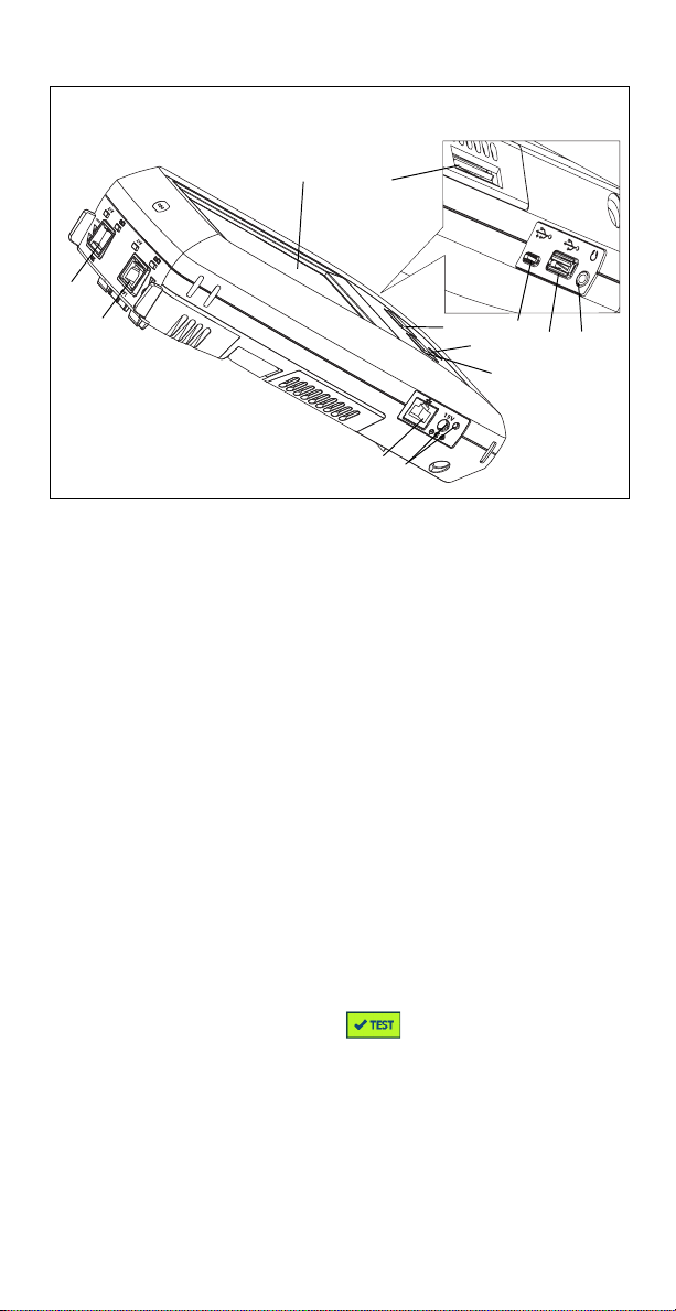
Connectors, Keys, and LEDs
Figure 1. Connectors, Keys, and LEDs
LCD display with touchscreen
Fiber Port SFP+ (1G / 10G) receptacle and activity lights, located
above receptacle. Connect the network under test to this port.
When a fiber module is present, the fiber port will attempt to
link before the Wired Ethernet Port.
Wired Ethernet Port and activity lights, located above
receptacle. This port is used for analysis and troubleshooting of
10G 802.3an copper, 1G 802.3ab copper, and 100M networks,
all at full duplex only.
Management Port – For remote control of the analyzer and
access to its locally stored files. Enter the device’s management
port IP address into a browser’s address field to connect
remotely to a device.
Connector for the AC adapter – The LED is red when the battery
charges, and green when the battery is fully charged.
– Press the HOME key to go to the main screen.
Power key
– The Test key links/unlinks and starts/stops a test
depending on whether you are starting a test or whether it is in
progress. You can also tap the button on the display.
Headset jack.
Type A USB port – use it to install software updates, import and
export profiles, and copy screenshots.
Micro - AB USB port – This connector is reserved for future use.
SD card slot – You can import or export profiles and other files
using the SD card.
Page 3
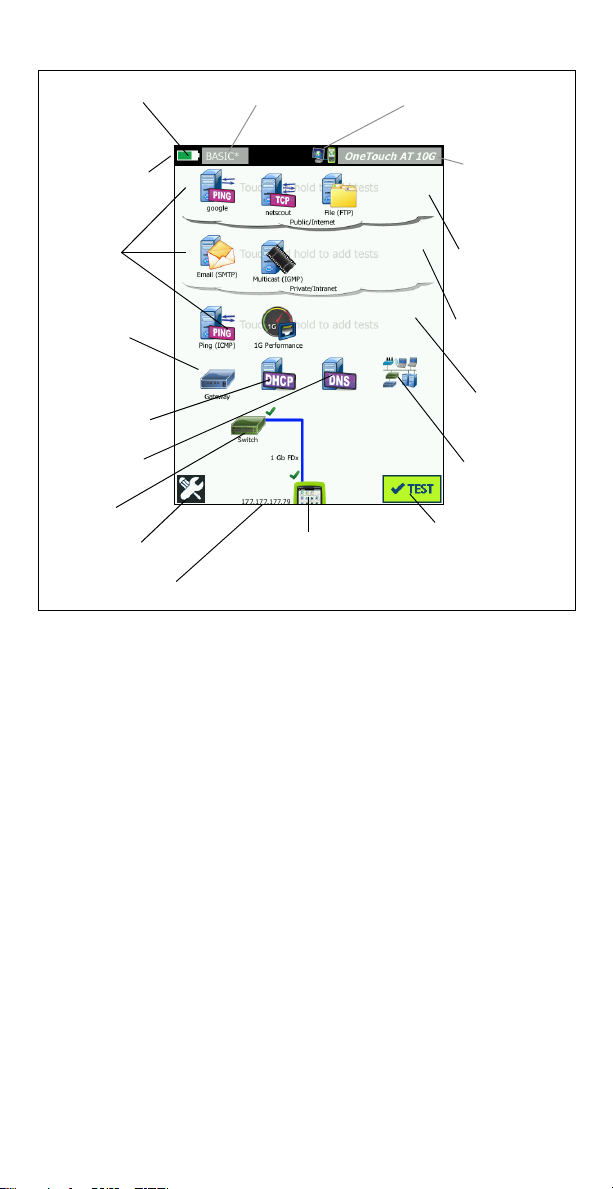
The HOME Screen
Remote
Indicator
Battery Icon
Profile Name
Shortcut Bar
Test
Tiers
Default
Gat ewa y
DHCP Server
DNS Server
Nearest
Switch
TOOLS button
IP Address
AutoTest Button
OneTouch AT 10G
Instrument icon
Discovery
Local
Network
Private
Network
Public
Network
Tap f o r
Reports and
Screenshots
Figure 2. The HOME Screen
The Shortcut Bar is located at the top of the display. When all tests
complete, the Shortcut Bar turns green if all tests passed, or red if
any test failed.
The Battery Icon turns red when the charge falls below 20%.
Tap Profile Name to save, load, and manage test profiles.
An asterisk (*) next to the Profile Name indicates that the Profile
contains changes that have not been saved.
The Remote Indicator appears when a remote connection to
the OneTouch analyzer is established.
Tap t h e OneTouch AT 10G button to take a screen shot or to
ve a comprehensive report.
sa
The Test Tier s contain User Tests, which are custom tests that you
can create and modify.
Touch and hold white space on test tier to add a new User Test.
Tap a User Test icon and then tap the SETUP tab to configure the
test. Tap the RESULTS tab to see the test’s results.
Touch and hold a User Test if you want to move, copy, or delete
it.
etwork infrastructure tests are located below the user tests.
N
Tap t h e Default Gateway icon to identify the IP and MAC
Page 4

addresses of the current Default Gateway, along with Wired
Gateway SNMP information and Receive Transmit statistics.
Configure SNMP for the most complete results. Tap the TOOLS
button , then tap Analysis.
Tap t h e DHCP Server to view the process and results of
acquiring an IP address via DHCP on the wired connection.
Tap t h e DNS Server button to view the performance of DNS
rvers resolving the specified URL.
se
Tap t h e Discovery icon to see devices discovered in the
oadcast domain.
br
The Nearest Switch is located below the network infrastructure
tests.
Tap t h e Nearest Switch to show the switch name, model, port
VLAN of the wired connection. If SNMP is enabled,
and
additional information is available.
The media tests are next as you move down the screen.
Cable/Link provides:
·
unterminated cable length.
· detects shorts, opens, splits, or good termination for each pair.
· link speed and duplex.
The following icons are at the bottom of the screen.
TOOLS are discussed later in this document.
The IP address is shown to the left of the OneTouch Instrument
icon.
Tap t h e OneTouch AT 10G instrument icon for network
connection details
The Test button initiates link and runs infrastructure
tests and user tests.
, errors, statistics, and more.
How to Run an AutoTest
AutoTest provides a comprehensive test of network infrastructure
tests, along with user-defined tests.
The OneTouch analyzer does not initiate any link, user test, or
infrastructure test activity until you run AutoTest.
1. Power the Analyzer
Connect the AC adapter to charge the battery if necessary.
2. Connect to the Network
Connect the network under test to a port (Items or in Figure 1).
You can use the RJ45 Ethernet jack for copper cable, or an SFP+
inserted in the SFP+ receptacle for fiber cable.
3. Run AutoTest
Tap the icon or press the AutoTest key (on the front panel).
The OneTouch analyzer will:
Link on active port (fiber or copper)
Page 5

Obtain IP address
Run Network Infrastructure Tests
Run User Tests
When multiple User Tests are present, they run starting with the
lower-left test on the bottom test tier and finishing with the
upper-right test on the top test tier.
4. View the Test Results
To see a test’s detailed results,
tap its icon.
The test’s status (pass or fail
) is indicated at the lower left
corner of the RESULTS tab.
When you tap the AutoTest key
or the Test button again, all test
results are cleared and the tests
run again.
5. Create a Report
To create a comprehensive
network performance test
report:
1
Tap t he OneTouch AT 10G
, which
button
is in the shortcut bar at the top of the HOME screen.
2Tap the Save Report button.
3 Change the file name if desired, then tap the DONE button.
You can also configure your OneTouch to automatically upload test
results to the Link-Live Cloud Service. See “How to Claim your
OneTouch AT 10G to the Link-Live Cloud Service” on the next page.
To manage reports on your OneTouch, tap the TOOLS button, then
scroll down to the File Tools section. Select the Reports button to
open the report file manager.
6. Add a User Test
Touch and hold white space on a test tier to add a new User Test.
Run AutoTest again to view the results.
7. Save a Profile
To save a Profile:
1
Configure the analyzer as desired (add User Tests, change
settings, etc.).
2 Tap the Profile name, which is in the shortcut bar at the top of
the HOME screen.
3Tap the SAVE button.
4 To create a new profile, enter its name and tap the DONE
button. To use the existing name, tap the DONE button.
Page 6

Load a Different Profile
To load a profile, tap the profile name at the top of the screen, and
select the profile you want to load from the list.
How to Claim your OneTouch AT 10G to the Link-Live Cloud Service
Link-Live Cloud Service is a free, online system for viewing, tracking,
and organizing your test results, which can be automatically
uploaded once you claim your device.
1
Create an account at Link-Live.com, or if you already have an
account, sign in.
If you are a new Link-Live user, a pop-up box will appear
automatically and prompt you to claim a device.
2 In the Link-Live Claim Unit pop-up bo x, select the OneTouch AT
image.
3 Follow the on-screen instructions to finish claiming.
Tools
Tap the TOOLS button to access:
Setup Wizard–will guide you in configuring your device profiles.
Tes t Sett ings–connection settings.
Cloud Tools–use to interact with the Link-Live Cloud Service:
AutoTest, Trending, Claim Unit, Unit Name, and Cloud Remote.
Testing Tools–Capture, Performance Peer, Browser, Telnet/SSH,
Flash Port, and FiberInspector/WebCam.
File Tools–use to manage profiles, reports, and screen captures.
Maintenance Tools–battery status, language, date and time,
units, display brightness, management port, update software,
etc.
Symbols, Certification and Compliance
Warning or Caution. Risk of damage or destruction to
equipment or software.
Warning: Risk of fire, electric shock, or personal injury.
Warning: Class 1 laser when an SFP/SFP+ module is installed.
Do not look directly into optical connectors. Risk of eye
damage from hazardous radiation.
Conformite Europeene. Conforms to the requirements of the
European Union and the European Free Trade Association
(EFTA).
Listed by the Canadian Standards Association.
This product complies with Australian standards.
Page 7

Meets RoHS directive.
Do not put products containing circuit boards into the garbage.
Dispose of circuit board in accordance with local regulations.
Do not connect the device to a telephone line or an ISDN line.
Conforms to relevant South Korean EMC Standards.
Electromagnetic
Compatibility. Applies to use
in Korea only. Class A
Equipment (Industrial
Broadcasting &
Communications Equipment)
This product meets requirements for
industrial (Class A) electromagnetic
wave equipment and the seller or
user should take notice of it. This
equipment is intended for use in
business environments and is not to
be used in homes.
General Specifications
Battery Type: Rechargeable lithium ion battery pack
Temperature:
Operating: 32°F to 122°F (0°C to +50°C)
Charging: 0 C to +40 C
Storage: -40°F to 160°F (-40°C to +71°C)
Operating altitude: 13,123 ft (4,000 m) and 10,500 ft (3,200 m) with
AC adapter
Storage altitude: 39,370 ft (12,000 m)
Safety: IEC 61010-1: CAT None, Pollution Degree 2
EMC: IEC 61326-1: portable
Technical Specifications
You can find the Product’s technical specifications in the User
Manual, available online at enterprise.netscout.com.
Registration
Registering your product gives you access to valuable information
on product updates, troubleshooting tips, and other support
services. To register online, visit enterprise.netscout.com/
registration.
The Setup Wizard, which appears when you initially power on the
analyzer, guides you through registering the product and
configuring the analyzer’s settings and tests.
To check your Registration status, tap TOOLS , and under
Maintenance Tools, tap Product Registration.
Page 8

Contact NETSCOUT
enterprise.netscout.com
customercare@netscout.com
Toll free: +1-844-833-3713
International: 978-320-2150
For more contact information, go to our website.
Use of this product is subject to the End User License Agreement available
LEGAL NOTIFICATION
at http://www.netscout.com/legal/terms-and-conditions/ or which
accompanies the product at the time of shipment or, if applicable, the legal
agreement executed by and between NETSCOUT SYSTEMS, INC., and the
purchaser of this product ("Agreement").
Government Use and Notice of Restricted Rights: In U.S. government
("Government") contracts or subcontracts, Customer will provide that the
Products and Documentation, including any technical data (collectively
"Materials"), sold or delivered pursuant to this Agreement for Government
use are commercial as defined in Federal Acquisition Regulation ("FAR")
2.101and any supplement and further are provided with RESTRICTED
RIGHTS. All Materials were fully developed at private expense. Use,
duplication, release, modification, transfer, or disclosure ("Use") of the
Materials is restricted by the terms of this Agreement and further restricted
in accordance with FAR 52.227-14 for civilian Government agency purposes
and 252.227-7015 of the Defense Federal Acquisition Regulations
Supplement ("DFARS") for military Government agency purposes, or the
similar acquisition regulations of other applicable Government
organizations, as applicable and amended. The Use of Materials is
restricted by the terms of this Agreement, and, in accordance with DFARS
Section 227.7202 and FAR Section 12.212, is further restricted in
accordance with the terms of NETSCOUT's commercial End User License
Agreement. All other Use is prohibited, except as described herein.
This Product may contain third-party technology. NETSCOUT may license
such third-party technology and documentation ("Third-Party Materials")
for use with the Product only. In the event the Product contains Third-Party
Materials, or in the event you have the option to use the Product in
conjunction with Third-Party Materials (as identified by NETSCOUT in the
applicable Documentation), then such third-party materials are provided or
accessible subject to the applicable third-party terms and conditions
contained in the "Read Me" or "About" file located on the Application CD for
this Product. To the extent the Product includes Third-Party Materials
licensed to NETSCOUT by third parties, those third parties are third-party
beneficiaries of, and may enforce, the applicable provisions of such thirdparty terms and conditions.
Open-Source Software Acknowledgment: This product may incorporate
open-source components that are governed by the GNU General Public
License ("GPL") or licenses that are compatible with the GPL license ("GPL
Compatible License"). In accordance with the terms o f the GNU GPL,
NETSCOUT will make available a complete, machine-readable copy of the
source code components of this product covered by the GPL or applicable
GPL Compatible License, if any, upon receipt of a written request. Please
identify the product and send a request to:
NETSCOUT SYSTEMS, INC. reserves the right, at its sole discretion, to make
changes at any time in its technical information, specifications, service, and
support programs. Rev. 02/04/2016
99 Washington Street
Melrose, MA 02176
Phone 781-665-1400
Toll Free 1-800-517-8431
Visit us at www.TestEquipmentDepot.com
 Loading...