

Page 1
Released 03/2016
Copyright © 2016 NETSCOUT SYSTEMS, INC. All rights reserved.
All product names are trademarks of their respective companies.
®
Wi-Fi
is a registered trademark of the Wi-Fi Alliance.
™
AirCheck
Wireless Tester
User Manual
G2
Page 2

LEGAL NOTIFICATION
Use of this product is subject to the End User License Agreement available at http://www.netscout.com/legal/terms-and-conditions/
or which accompanies the product at the time of shipment or, if applicable, the legal agreement executed by and between NETSCOUT
SYSTEMS, INC., and the purchaser of this product ("Agreement").
Government Use and Notice of Restricted Rights: In U.S. government ("Government") contracts or subcontracts, Customer will provide
that the Products and Documentation, including any technical data (collectively "Materials"), sold or delivered pursuant to this Agreement
for Government use are commercial as defined in Federal Acquisition Regulation ("FAR") 2.101and any supplement and further are
provided with RESTRICTED RIGHTS. All Materials were fully developed at private expense. Use, duplication, release, modification, transfer,
or disclosure ("Use") of the Materials is restricted by the terms of this Agreement and further restricted in accordance with FAR 52.227-14
for civilian Government agency purposes and 252.227-7015 of the Defense Federal Acquisition Regulations Supplement ("DFARS") for
military Government agency purposes, or the similar acquisition regulations of other applicable Government organizations, as applicable
and amended. The Use of Materials is restricted by the terms of this Agreement, and, in accordance with DFARS Section 227.7202 and FAR
Section 12.212, is further restricted in accordance with the terms of NETSCOUT's commercial End User License Agreement. All other Use is
prohibited, except as described herein.
This Product may contain third-party technology. NETSCOUT may license such third-party technology and documentation ("Third-Party
Materials") for use with the Product only. In the event the Product contains Third-Party Materials, or in the event you have the option to
use the Product in conjunction with Third-Party Materials (as identified by NETSCOUT in the applicable Documentation), then such thirdparty materials are provided or accessible subject to the applicable third-party terms and conditions contained in the "Read Me" or
"About" file located on the Application CD for this Product. To the extent the Product includes Third-Party Materials licensed to NETSCOUT
by third parties, those third parties are third-party beneficiaries of, and may enforce, the applicable provisions of such third-party terms
and conditions.
Open-Source Software Acknowledgment: This product may incorporate open-source components that are governed by the GNU General
Public License ("GPL") or licenses that are compatible with the GPL license ("GPL Compatible License"). In accordance with the terms of the
GNU GPL, NETSCOUT will make available a complete, machine-readable copy of the source code components of this product covered by
the GPL or applicable GPL Compatible License, if any, upon receipt of a written request. Please identify the product and send a request to:
NETSCOUT SYSTEMS, INC.
GNU GPL Source Code Request
310 Littleton Road
Westford, MA 01886
Attn: Legal Department
NETSCOUT SYSTEMS, INC. reserves the right, at its sole discretion, to make changes at any time in its technical information, specifications,
service, and support programs.
Rev. 02/04/2016
Page 3

Table of Contents
I. Introduction ..................................................................................................................................................1
Link-Live Cloud Service ....................................................................................................................................................1
AirCheck G2 Manager ......................................................................................................................................................2
About this Manual ............................................................................................................................................................2
Register Your Product ......................................................................................................................................................2
The NETSCOUT/Fluke Networks Website ......................................................................................................................3
Contact NETSCOUT ...........................................................................................................................................................3
Safety Information ............................................................................................................................................................3
Package Contents .............................................................................................................................................................5
Internal Battery Charging and Life .................................................................................................................................5
II. AirCheck G2 Tester Physical Features ......................................................................................................6
III. The AirCheck G2 Home Screen .................................................................................................................7
IV. Discovering Networks and Access Points ................................................................................................9
The Networks List Screen ................................................................................................................................................10
How to: Search for Ad-Hoc networks ............................................................................................................................................12
The Network Details Screen ............................................................................................................................................12
The Access Points List Screen .........................................................................................................................................14
The Access Point Details Screen .....................................................................................................................................17
Troubleshoot: If the Tester Does Not Discover an Access Point or Network ............................................................19
i
Page 4

V. Viewing Channel Usage ............................................................................................................................. 20
The Channels Utilization Screen ....................................................................................................................................20
The Select Channel Screen ..............................................................................................................................................22
The Channel Details Screen ............................................................................................................................................23
VI. Discovering Clients ..................................................................................................................................... 24
The Client List Screen ......................................................................................................................................................24
The Client Details Screen ................................................................................................................................................ 26
Troubleshoot: If the Tester Does Not Discover a Client .............................................................................................. 28
VII. Using AutoTest to Diagnose Your Network Health ................................................................................ 29
AutoTest Air Quality .........................................................................................................................................................29
802.11 Utilization .................................................................................................................................................................... 30
Non-802.11 Utilization ........................................................................................................................................................... 30
Co-Channel Interference ....................................................................................................................................................... 31
Adjacent Channel Interference ............................................................................................................................................. 31
AutoTest Network Tests .................................................................................................................................................. 32
How to: Run Network Quality Tests as part of AutoTest .............................................................................................................32
Connection Test Results ........................................................................................................................................................ 33
IP and Target Test Results ..................................................................................................................................................... 34
VIII. Testing Ethernet for Access Point Backhaul ........................................................................................... 36
The Ethernet Test Results Screen .................................................................................................................................. 36
IX. Companion Services ..................................................................................................................................38
Getting Started in Link-Live Cloud Service ....................................................................................................................38
How to: Claim the AirCheck G2 to Link-Live .................................................................................................................................38
Getting Started with the AirCheck G2 Manager PC Application ................................................................................. 39
ii
Page 5

X. Customizing the Tester for your Network .............................................................................................. 40
Changing the Location Settings and Language ............................................................................................................40
How to: Change the location settings ...........................................................................................................................................40
How to: Change the language on the Tester ................................................................................................................................40
Entering Network Security Credentials .........................................................................................................................41
How to: Enter credentials from the Networks or Access Points list ........................................................................................... 41
How to: Enter credentials in the Settings menu ..........................................................................................................................42
How to: Enter credentials in AirCheck G2 Manager ....................................................................................................................42
Using Profiles to Manage Settings and Security Credentials ...................................................................................... 43
How to: Save the current settings as a Profile on the AirCheck G2 Tester ................................................................................44
How to: Transfer a Profile from a PC to the Tester .....................................................................................................................45
How to: Load a Profile that is saved in the AirCheck G2 Tester .................................................................................................45
How to: Delete a Profile on the Tester ..........................................................................................................................................46
Adjusting the Test Thresholds ........................................................................................................................................47
How to: Change the test thresholds on the Tester ......................................................................................................................47
XI. Verifying Connectivity and Coverage ....................................................................................................... 48
Defining Ping and TCP Port Open Test Targets ............................................................................................................48
How to: Add a new network Test Target .......................................................................................................................................49
Running a Connect to Network or Connect to AP Test ............................................................................................... 50
Reviewing Connect to Network or AP Results ..............................................................................................................51
Connection Established ......................................................................................................................................................... 51
IP Address ................................................................................................................................................................................ 51
Target Tests ............................................................................................................................................................................. 52
Reviewing User-Defined Test Target Results ................................................................................................................53
Next Steps ......................................................................................................................................................................... 54
iii
Page 6

XII. Locating an Access Point or a Client ........................................................................................................55
How to: Locate an AP or Client ......................................................................................................................................................55
How to: Search using the Internal Antennas ...............................................................................................................................56
The Locate AP Screen ......................................................................................................................................................57
The Locate Client Screen .................................................................................................................................................58
Using the External Directional Antenna ........................................................................................................................ 59
How to: Use the external antenna to locate ................................................................................................................................ 59
XIII. Performing a Network Roaming Test ...................................................................................................... 62
How to: Start a roaming test .........................................................................................................................................................62
How to: Select a custom test target ..............................................................................................................................................62
The Roaming Test Screen ................................................................................................................................................63
XIV. Performing an Access Point Range Test .................................................................................................. 66
How to: Start a Range Test .............................................................................................................................................................66
How to: Select a custom test target ..............................................................................................................................................66
The AP Range Test Screen ...............................................................................................................................................67
XV. Saving Test Sessions and Managing Files ................................................................................................ 69
Saving Sessions ................................................................................................................................................................69
How to: Save a test Session ............................................................................................................................................................69
Managing Files on the AirCheck G2 Tester ................................................................................................................... 70
How to: Rename and Delete a file .................................................................................................................................................70
How to: View available memory on the Tester ............................................................................................................................70
Using the Remote Interface ............................................................................................................................................71
Managing Profiles and Sessions on a PC using AirCheck G2 Manager ..................................................................... 71
How to: Transfer and view test sessions with AirCheck G2 Manager ........................................................................................71
iv
Page 7

How to: Transfer and view Profiles with AirCheck G2 Manager ................................................................................................72
How to: Load the latest list of vendor prefixes into the Tester ..................................................................................................73
XVI. All AirCheck G2 Settings ............................................................................................................................ 74
Profiles ...............................................................................................................................................................................74
Networks ...........................................................................................................................................................................74
How to: Add a network ...................................................................................................................................................................74
How to: Edit a network ...................................................................................................................................................................75
How to: Delete a network ...............................................................................................................................................................75
Access Points .................................................................................................................................................................... 75
How to: Add an AP ..........................................................................................................................................................................75
How to: Edit an AP ..........................................................................................................................................................................75
How to: Delete an AP ......................................................................................................................................................................75
802.11 Settings .................................................................................................................................................................76
Ethernet Settings ..............................................................................................................................................................78
How to: Configure a Test Target for Ethernet Tests ..................................................................................................................... 78
Thresholds ........................................................................................................................................................................ 79
AutoTest Settings ............................................................................................................................................................. 81
How to: Configure AutoTest settings .............................................................................................................................................81
Test Targets ......................................................................................................................................................................81
How to: Add a User-Defined Test Target ......................................................................................................................................82
How to: Edit a user-defined Test Target .......................................................................................................................................82
How to: Delete a user-defined Test Target ................................................................................................................................... 82
Location Settings ..............................................................................................................................................................83
Device Settings ................................................................................................................................................................. 83
Link-Live Settings .................................................................................................................................................................... 84
v
Page 8

About .................................................................................................................................................................................85
XVII. Maintenance ............................................................................................................................................... 86
Cleaning the Tester ..........................................................................................................................................................86
Updating the AirCheck G2 Firmware .............................................................................................................................87
Exporting a Troubleshooting Log ................................................................................................................................... 87
Restoring Factory Defaults ..............................................................................................................................................87
Viewing Device Information ............................................................................................................................................ 88
Troubleshoot: If the Tester Will Not Turn Off ...............................................................................................................88
XVIII.Specifications and Compliance ................................................................................................................ 89
Environmental Specifications .........................................................................................................................................89
General Specifications .....................................................................................................................................................90
Wireless Specifications ....................................................................................................................................................91
Wi-Fi Antennas ........................................................................................................................................................................ 92
Wi-Fi Adapter ........................................................................................................................................................................... 93
Certifications and Compliance .......................................................................................................................................96
Federal Communication Commission and Industry Canada Interference Statement ............................................97
Important Note: FCC and IC Radiation Exposure Statement ......................................................................................98
Exposure to RF Energy ..................................................................................................................................................... 98
Regulatory Statements ....................................................................................................................................................100
Appendix A: Quick Reference: Examining your Network Health ................................................................. 101
How is my Network Quality? ...........................................................................................................................................101
What is in the Wireless Environment? ...........................................................................................................................103
Can Devices Connect to My Network? ........................................................................................................................... 104
What is Causing Slow Network Performance or Dropped Connections? .................................................................106
Are There Security Risks in My Network? ...................................................................................................................... 106
vi
Page 9

Where is an Access Point? ............................................................................................................................................... 107
What Networks or Access Points Come into Range as I Move? .................................................................................107
How Can I Document My Network and My Test Session? .......................................................................................... 107
vii
Page 10

List of Figures
Figure Page
1. AirCheck G2 Physical Features ...................................................................................................................................6
2. AirCheck G2 Home Screen..........................................................................................................................................7
3. Networks List Screen...................................................................................................................................................10
4. Possible Ad-Hoc Network............................................................................................................................................12
5. Networks Sorted by Client Count...............................................................................................................................12
6. Network Details Screen...............................................................................................................................................12
7. Access Points List .........................................................................................................................................................15
8. Select BSSID to View AP Details..................................................................................................................................17
9. Access Point Details Screen ........................................................................................................................................17
10. Channels Utilization Screen........................................................................................................................................20
11. Select Channel Screen.................................................................................................................................................22
12. Channel Details Screen ...............................................................................................................................................23
13. Clients List Screen........................................................................................................................................................24
14. Client Details Screen....................................................................................................................................................27
15. AutoTest Air Quality Results Screen ..........................................................................................................................29
16. 802.11 Channel Utilization Results ............................................................................................................................30
17. Air Quality Co-Channel and Adjacent Channel Interference Results.....................................................................31
18. AutoTest Settings Screen ............................................................................................................................................32
19. AutoTest Results Screen..............................................................................................................................................32
viii
Page 11

20. AutoTest Network Connection Test Results .............................................................................................................33
21. AutoTest Network Test IP and Test Targets..............................................................................................................34
22. Ethernet Test Screen ...................................................................................................................................................36
23. Successful Link-Live Upload Field ..............................................................................................................................38
24. Session Data > Networks in AirCheck G2 Manager .................................................................................................39
25. Settings Menu Screen..................................................................................................................................................40
26. Network Details Screen...............................................................................................................................................41
27. Configured Networks in Settings ...............................................................................................................................42
28. Setting > Profiles Menu ...............................................................................................................................................44
29. Profiles > Save As .........................................................................................................................................................44
30. AutoTest Air Quality Results Screen ..........................................................................................................................47
31. Thresholds Screen .......................................................................................................................................................47
32. Settings > Test Targets Screen ...................................................................................................................................49
33. Configure Target Screen .............................................................................................................................................49
34. The Connect to AP Test Screen (In Progress) ...........................................................................................................50
35. The Connect to AP Test Results..................................................................................................................................51
36. Completed AP Connect Test Screen ..........................................................................................................................52
37. Connection Test Target Results..................................................................................................................................53
38. Completed Network Connect Test Screen................................................................................................................54
39. Search Pattern for the Omni-directional Antennas in the Tester ..........................................................................56
40. Locate Access Point Screen ........................................................................................................................................57
41. Locate Client Screen ....................................................................................................................................................58
42. Search Pattern for the External Antenna..................................................................................................................60
43. How to Point the External Antenna ...........................................................................................................................61
44. Network Roaming Test Screen...................................................................................................................................63
45. Roaming Test Ping Stats..............................................................................................................................................64
46. Roaming Test Connection Range...............................................................................................................................65
47. AP Range Test Screen..................................................................................................................................................67
ix
Page 12

48. AP Range Test Connection Range Graph ..................................................................................................................68
49. Save Session Screen ....................................................................................................................................................69
50. Manage Files Screen....................................................................................................................................................70
51. Transfer Sessions Button............................................................................................................................................71
52. Transfer Sessions Dialog Box .....................................................................................................................................72
53. oui_abbr.txt File............................................................................................................................................................73
54. Settings Menu Screen..................................................................................................................................................74
55. Test Targets Screen .....................................................................................................................................................81
56. Link-Live Settings Screen.............................................................................................................................................84
x
Page 13

I. INTRODUCTION
AirCheck™ G2 Wireless Tester
The AirCheck™ G2 Wireless Tester is a portable tool for
verifying network availability and performance and
troubleshooting connection issues. Networking and IT
professionals can, for example, use the AirCheck G2 Tester
to ensure that 802.11 wireless LANs are available to mobile
users or examine channel usage to identify the source of
problems.
The AirCheck G2 Tester operates on 802.11b/g/n networks in
the 2.4-GHz band and 802.11a/n/ac networks in the 5-GHz
band. It offers the following test types:
The high-level discovery screens for Networks, Access
Points, and Clients each show an overview of the
devices that AirCheck G2 has detected on your network.
From the discovery screens, you can touch any network
or device’s name to view its detailed connections and
measurements.
The Channels utilization screen allows you to examine
in-depth the usage for all channels in your network.
AutoTest provides a comprehensive summary of your
Wi-Fi Air Quality and Network Quality at the current
time and location.
The wired Ethernet Test measures PoE voltage and link
speed and indicates whether the Tester can connect to
network and user-defined targets.
The Locate function helps you physically find access
points and clients.
Network Roaming and AP Range tests define the
boundaries of your network.
In addition to the AirCheck G2 Tester hand-held tool, the
Link-Live Cloud Service and AirCheck G2 Manager PC
application provide managing, organizing, and documenting
capabilities for your Tester and test data.
Link-Live Cloud Service
The Link-Live Cloud Service is a free, online system for
viewing, tracking, and organizing your AirCheck G2 test
Page 14

results, which are automatically uploaded to Link-Live once
configured. To start, create a user account at Link-Live.com.
See “Getting Started in Link-Live Cloud Service,” page 38.
AirCheck G2 Manager
The AirCheck™ G2 Manager PC application allows you to
configure Tester Profiles; transfer, store, organize, and report
test results; and update your AirCheck G2 Tester software.
For example, you can use AirCheck G2 Manager to compare
information from different test sessions to see changes in a
wireless LAN and generate reports based on test data.
Download the AirCheck G2 Manager software from Link-Live
at https://app.link-live.com/downloads
See “Getting Started with the AirCheck G2 Manager PC
Application,” page 39.
.
About this Manual
This User Manual co
with additional details not covered in the embedded Help on
the Tester.
It is designed to be easy to navigate on a screen, with Adobe
PDF Bookmarks to the left, and blue hyperlinks that point to
content in other parts of the manual. Blue underlined links
go to external resources on the internet.
vers all AirCheck G2 Tester functionality,
Register Your Product
Registering your product with NETSCOUT gives you access
to valuable information on product updates,
troubleshooting procedures, and other services. To register,
fill out the online form on the NETSCOUT website at
http://enterprise.netscout.com/register.
2
Page 15
The NETSCOUT/Fluke Networks Website
Safety Information
The NETSCOUT (formerly Fluke Networks) website provides
additional documentation, release notes, software updates,
and other resources.
Go to http://enterprise.netscout.com, and click Support.
Contact NETSCOUT
Online: http://enterprise.netscout.com
Email: CustomerCare@netscout.com
Phone: 1-844-833-3713
For more phone numbers, go to our website.
Table 1 gives descriptions of the safety symbols used on the
Tester and in this manual.
Table 1. Safety Symbols
Warning or Caution: Risk of damage to or
destruction of equipment or software.
Warning: Risk of electrical shock.
This product complies with the WEEE Directive
marking r
indicates that you must not discard this
electrical/electronic product in domestic
household waste.
Product Category: With reference to the
equ
this product is classed as category 9
“Monitoring and Control Instrumentation”
product. Do not dispose of this product as
unsorted municipal waste.
This equipment contains a Class 2 radio.
equirements. The affixed label
ipment types in the WEEE Directive Annex I,
3
Page 16

Warning
Read all safety information before using this Product.
Carefully read all instructions.
Use the Product only as specified, or the protection
supplied by the Product can be compromised.
Use only manufacturer approved power adapters to
charge the battery.
Do not use the Product around explosive gas, vapor,
or in damp or wet environments.
Examine the case before you use the Product. Look
for cracks or missing plastic. Carefully look at the
insulation around the terminals.
Do not operate the Product with covers removed or
the case open. Hazardous voltage exposure is
possible if connected to a PoE source.
Batteries contain hazardous chemicals that can
cause burns or explode. If exposure to chemicals
occurs, clean with water and get medical aid.
Do not short the battery terminals together.
Do not disassemble or crush battery cells and battery
packs. Do not put battery cells and battery packs
near heat or fire. Do not put in sunlight.
Caution
If you use an external antenna, use only the antenna
made for the AirCheck G2 Tester. The Tester may not
operate correctly with other antennas and may
violate local regulations.
Any adjustment to the device’s controls or operation
must not violate your local regulations on lowpower-radio-wave emitting devices.
Any adjustments to the Product should be performed
by a technician with expertise on radio frequency
devices maintenance.
Do not attempt to open the unit or replace any
internal device components (ICs, transistors, etc.),
which may lead to violation of local regulations as
well as void the Product warranty.
U-NII devices operating in the 5.25-5.35 GHz and 5.47-
5.725 GHz band, without radar detection are
restricted to use in indoors.
4
Page 17
Package Contents
Internal Battery Charging and Life
The AirCheck G2 Wireless Tester comes with the accessories
in the list below. If something is damaged or missing, tell the
dealer where you purchased the product.
AirCheck G2 with internal rechargeable battery
AC adapter
USB cable for connecting the Tester to a PC
Carrying case
Quick Start Guide
Compliance Document
Charge the battery for 3 hours before you use it for the first
time. When the Tester is off, the battery charges in
approximately 7 hours. However, you can use the Tester
while you charge the battery.
To charge the battery, connect the ac adapter to the Charging
Port, shown in Figure 1 on page 6.
The battery life is approximately 4.5 hours during typical
operation.
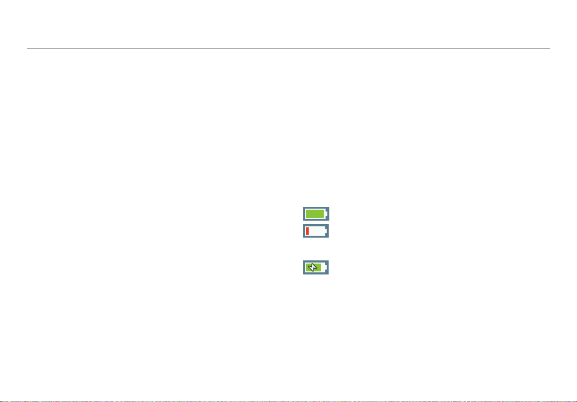
The battery icon in the upper-right corner of the screen
visually displays the amount of charge remaining before the
internal battery is completely drained:
The battery is fully or almost fully charged.
The battery life is low. Connect the ac adapter
to the charging port to charge the battery and
ensure the Tester continues to operate.
The ac adapter is connected to the charging
port.
NOTE: The battery will not charge if the internal temperature
of the Tester is above 122ºF (50ºC).
5
Page 18
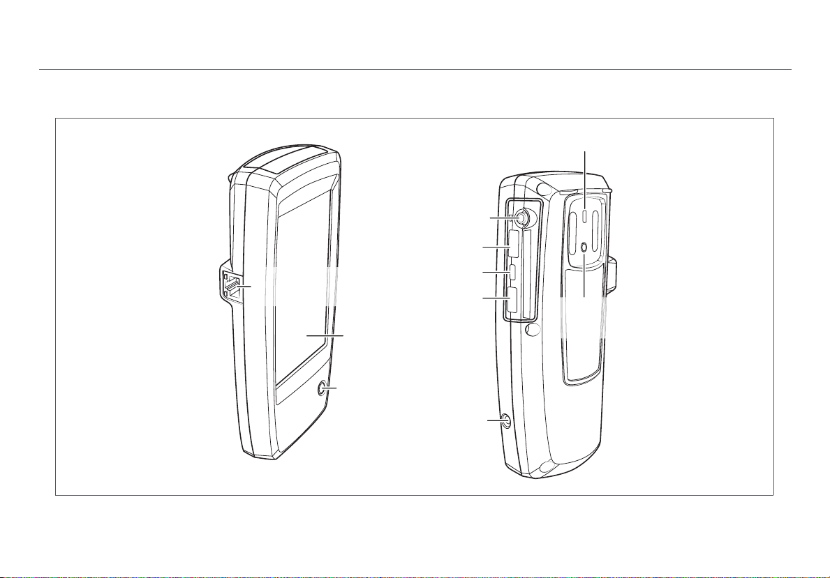
II. AIRCHECK G2 TESTER PHYSICAL FEATURES
Power Button: Turns
the Tester unit on or off.
When the Tester is off,
press this button to
power on.
When the Tester is on,
press for one second
to shut it down.
For “hard” power off,
without software
shutdown, press for
four seconds.
The Power LED glows
green when the unit is
on and glows red when
the battery is charging
but the unit is off.
Once the battery is fully
charged, the LED turns
off.
Charging Port:
Connects with the AC
adapter to charge the
unit’s internal battery.
External Antenna:
Sold separately.
USB Port 1: For
500mA of current (any
supported USB
peripheral)
Micro USB Port 2: For
communication with
AirCheck G2 Manager
over a USB Micro-toType-B cable
USB Port 3: For
200mA of current, e.g.,
thumb drives, etc.
RJ-45 Ethernet
Port
10/100/1000 Mbps
Touchscreen
Power Button
and LED
Figure 1. AirCheck G2 Physical Features
External
Antenna
Connector
USB Port 3
Micro USB Port 2
USB Port 1
Charging
Port
6
AirCheck G2 Tester Physical Features
Kensington
Lock
External
Antenna
Holder
Page 19

III. THE AIRCHECK G2 HOME SCREEN
Figure 2. AirCheck G2 Home Screen
The AirCheck G2 Home Screen
The AirCheck G2 Wireless Tester features a full color
touchscreen. Touch functions are noted in the following
descriptions of the Home Screen components:
Profile Name: This field displays the name of the Profile
the Tester is currently using. The Profile is Default if you
have not created a custom Profile. The name shows an
asterisk (*) if you have changed a Profile-related setting
on the Tester since you loaded or saved the Profile.
See “Customizing the Tester fo
40.
This Transmitting Indicator appears when the
Tester is actively transmitting packet data.
The Channel Indicator Shows the Wi-Fi
channel that AirCheck G2 is scanning in real
time.
The Battery Life Indicator visually displays the
amount of charge remaining.
r your Network,” page
Networks (#) : This function discovers wireless
LANs and displays the number of networks discovered in
parentheses. Touch this row to view the discovered
Networks list screen. See “Discovering Networks and
Access Points,” page 9.
7
Page 20
The AirCheck G2 Home Screen
Channels : This function illustrates usage of WLAN
channels. Touch to view the Channel Utilization screen.
See “Viewing Channel Usage,” page 20.
Access Points (#) : This function discovers access
points and displays the number disco
view the discovered Access Points list. See “Discovering
Networks and Access Points,” page 9.
vered. Touch to
Clients : This function discovers associated and un-
associated (e.g., probing) clients and displays the
number discovered. Touch to view the discovered
Clients list. See “Discovering Clients,” page 24.
AutoTest : This function automatically checks the
health of your network by measuring air quality (channel
e and interference) and configured networks. Touch
usag
to begin AutoTest and open the AutoTest screen. See
“Using AutoTest to Diagnose Y
page 29.
our Network Health,”
Ethernet Test : This function runs a wired network
test across 10/100/1000 Mbps links and verifies Power
over Ethernet (PoE). Touch this row to begin an Ethernet
test and open the Ethernet Test screen. See “Testing
Ethernet for Access Point Backhaul,” page 36.
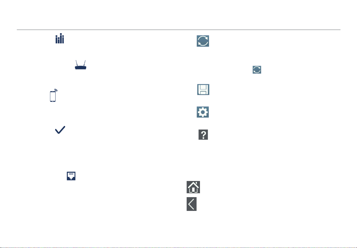
Refresh: Touch this icon to clear the current
results and restart the current discovery or
testing process.
Caution
Touching the Refresh button will
erase all unsaved test results.
Save: Touch this icon to save your current
test results to a session file. See “Saving
Sessions,” page 69.
Settings: Touch this icon to manage your
Tester’s settings and files. See “All AirCheck G2
Settings,” page 74.
Help: Touch this icon to open the relevant
Help topic for the screen.
To save a screen capture, hold your finger on
the icon for three seconds to save an image
of the current screen to internal storage on
the Tester. The Tester beeps once when a
screenshot is saved.
Touch the Home button to return to the Home Screen
from any other screen on the AirCheck G2 Tester.
Touch the Back button to return to the previous screen
from any screen except the Home Screen.
8
Page 21
IV. DISCOVERING NETWORKS AND ACCESS POINTS
Discovering Networks and Access Points
The Networks list and the Access Points list are populated
with SSIDs and access points that have been discovered by
the AirCheck G2 Tester in your location.
1
From the Home Screen, select Networks or Access
Points. The Tester shows the Networks list (Figure 3) or
Access Points list (Figure 7).
2
To see details about a network or access point, touch its
row in the list to open the Network or AP Details screen.
NOTES:
By default, the Tester hears wireless signals on both the
2.4-GHz (b/g/n) and
change this setting, from the Home Screen, go to
Settings > 802.11 Settings > Bands.
The Netwo
update with each update cycle.
An SSID is in bl
in range.
rks and Access Points screens automatically
5-GHz (a/n/ac) frequency bands. To
ack text if the network (or access point) is
An SSID’s row background
turns gr
network (or access point)
has not been heard for the last four scans, or is now ou t of
range
If a network name is shown as [H
does not broadcast its SSID.
If an SSID shows in square brackets, the Tester found the
hidd
Colored bars that indicate the status or rating of Signal
Str
Thresholds, which can be configured in
See “Adjusting the Test Thresholds,” page 47.
ay to indicate that a
.
idden], the network
en SSID in packets from other wireless clients.
ength and Level, Noise, and SNR are controlled by
Settings.
9
Page 22
The Networks List Screen
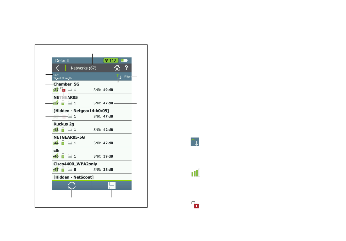
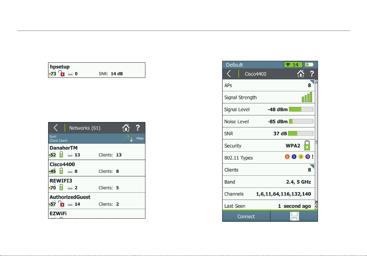
Figure 3. Networks List Screen
Discovering Networks and Access Points
The Networks list screen provides an overview of the Wi-Fi
networks that the AirCheck G2 has discovered in your
environment. The networks are identified by SSID.
Networks (#): The screen title displays the number of
networks discovered by the Tester.
Sort (Option Field): This field shows the sort option that
is currently applied. In Figure 3, the sort option applied is
Signal Strength.
Touch the So
networks are listed. The value by which the list is sorted
shows prominently for each network. For example, if you
change to Sort by Client Count, the Networks list screen
displays the number of connected Clients on each
network (See Figure 5), instead of the SNR, as shown in
Figure 3.
This is the default.
rt: field to change the order in which
Sort Order Button: These arrows switch the list
order from ascending to descending, and vice versa.
SSID: Service Set Identifier; The name of the wireless
network.
Signal Strength Bar Graph: The signal strength in
dBm of the AP with the strongest signal strength
connected to the network.
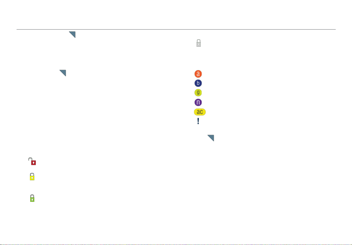
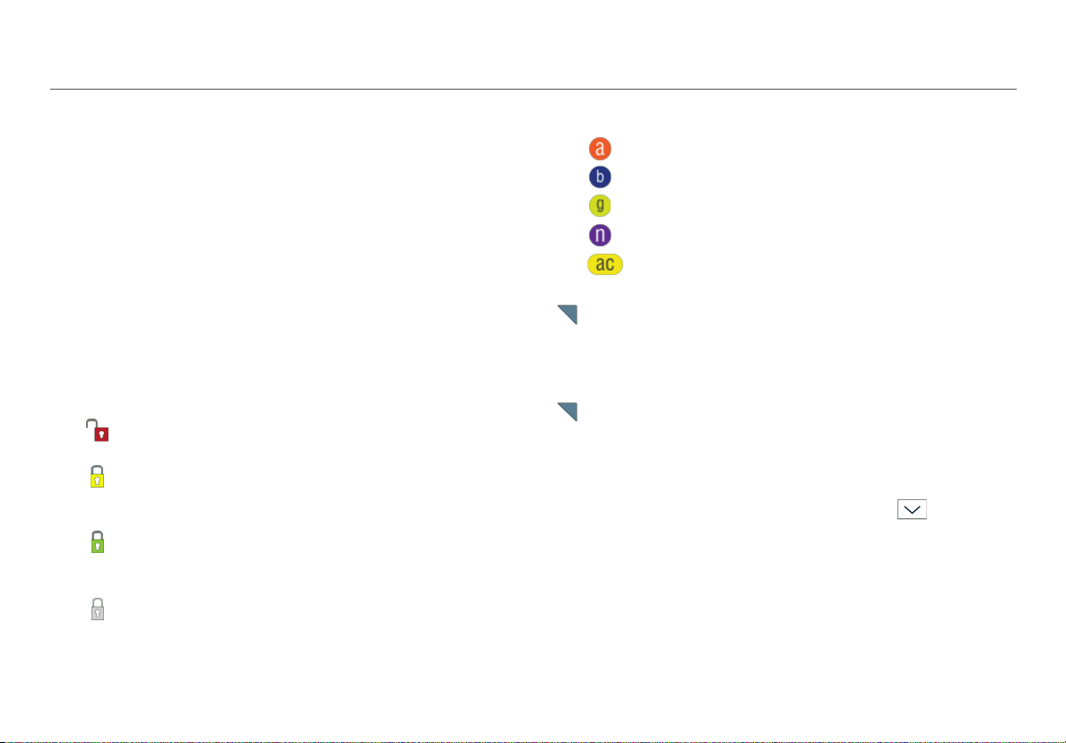
Security status of the network:
Red open lock: The network does not have security
enabled.
10
Page 23
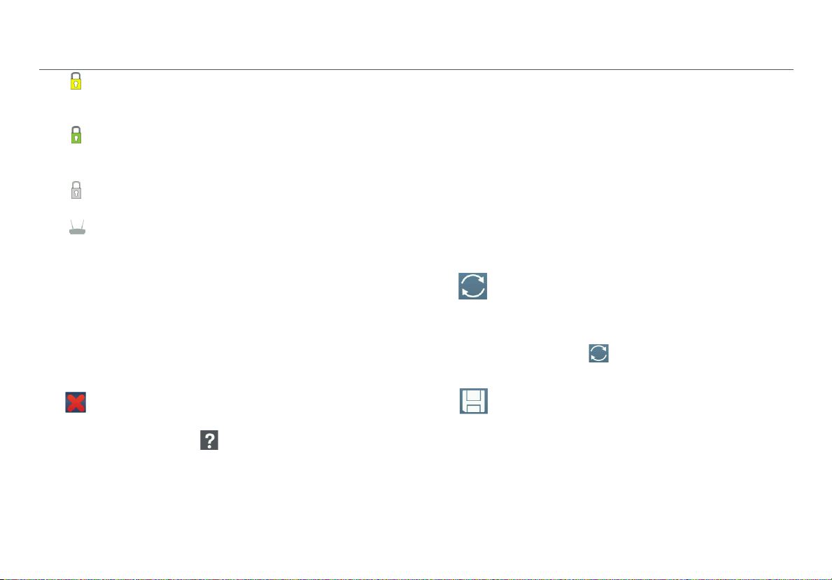
Yellow closed lock: One or more access points use
WEP or Cisco LEAP security protocol. These are less
secure than other protocols.
Green closed lock: All access points use security
protocols that are more secure than WEP, for example,
WPA or WPA2.
Gray closed lock: Access points on this network are
using multiple security protocols.
Access Points #: The number displayed next to the
icon is the number of access points near your location.
Filter Button: Touch this field to add a filter for specific
network characteristics, such as SSID string, minimum
signal strength, or 802.11 media type.
NOTE: You can set only one filter at a time. Once a filter is
set, the Networks list screen re-opens. The title of the
screen changes to “Networks (X of Y)”, such that
X = the number of networks filtered, and
Y = the total number of networks discovered.
This icon appears to the right of the active filter.
Touch the icon to remove the filter.
Touch the Help button on the Filter Networks By:
screen for more detail about each option.
Discovering Networks and Access Points
SNR: Signal-to-Noise Ratio, a measure of signal strength
relative to noise. The ratio is measured in decibels (dB).
NOTE: For networks, the SNR of the strongest AP in the
network is displayed.
This is also soft field, which changes based on the Sort
option currently applied. For example, if the list is sorted
by Client Count, the number of clients connected to the
network will appear in this space on the screen (as
shown in Figure 5).
For Networks, this space can also show the 802.11 Type,
Band, or time since the network was Last Seen.
Refresh: Touch this icon to clear the current
results and restart the current discovery
process.
Caution
Touching the Refresh button will
erase all unsaved test results.
Save: Touch this button to save a session file
containing all discovered networks, APs,
channels, and clients. The session file will also
include all test results for any saved
AutoTests, connection tests, Ethernet tests,
and roaming and range tests. See “Saving
Sessions,” page 69.
11
Page 24
Discovering Networks and Access Points
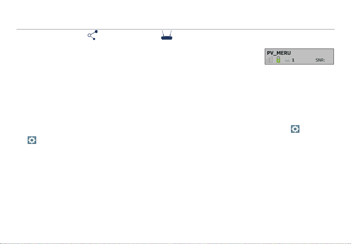
How to: Search for Ad-Hoc networks
On the Networks list screen, look for networks with 0 APs
and 1 or more clients. These could be Ad-Hoc Networks.
Figure 4. Possible Ad-Hoc Network
For help searching, Sort the Networks list by Client Count to
be able to see the number of connected clients for each
discovered network on the list screen. Figure 5 shows the
Networks list sorted by Client Count:
The Network Details Screen
Touch any network’s row on the Networks list screen (Figure
3) to open the Network Details screen.
Figure 5. Networks Sorted by Client Count
Figure 6. Network Details Screen
12
Page 25
This triangle symbol in the top right corner of a field
indicates that you can touch the field to go to a new screen.
Touch functions are explained in the following descriptions:
Screen Title: The SSID of the network shown.
APs: The number of access points detected on this network
at your location. Touch this row to open the Access
Points list screen with the APs filtered for the selected
network.
Signal Strength: The signal strength of the strongest AP on
the network.
Signal Level: The signal level in dBm from the strongest AP.
Noise Level: The noise level in dBm from the environment.
SNR: Signal-to-Noise Ratio is a measure of signal strength
relative to noise; an indication of signal quality for a reliable
client’s connection. The ratio is measured in decibels (dB).
Security status of the network:
Red open lock: The network does not have security
enabled.
Yellow closed lock: One or more access points use
WEP or Cisco LEAP security protocol. These are less
secure than other protocols.
Green closed lock: All access points use security
protocols that are more secure than WEP, for example,
WPA or WPA2.
Discovering Networks and Access Points
Gray closed lock: Access points on this network are
using multiple security protocols.
802.11 Types: The 802.11 standards that the access points in
the network use:
802.11a: Uses the 5-GHz band.
802.11b: Uses the 2.4-GHz band.
802.11g: Uses the 2.4-GHz band.
802.11n: Can be used in the 2.4 GHz or 5 GHz bands.
802.11ac: Uses the 5-GHz band.
Two or more APs use different sets of 802.11 types.
Clients: The number of Wi-Fi clients discovered on the
network. Touch this row to open the Clients screen,
which shows all clients filtered for the selected network.
Band: The radio band used by the network: 2.4 GHz, 5 GHz,
or both.
Channels: The Wi-Fi channels used by the network.
NOTES:
For 20-MHz channels, the Tester displays the channel
number.
13
Page 26

For 40-, 80-, and 160-MHz channels, it displays the
primary channel number.
For multiple channels, it displays all channel numbers
if space permits; otherwise, it truncates to what fits,
followed by "...".
Last Seen: The time since the last packet was detected from
the selected network.
Connect: Touch this button to connect to the Wi-Fi network
and run a Connection test.
Save: Touch this button to save a session file containing
all discovered networks, APs, channels, and clients. The
session file will also include all test results for any saved
AutoTests, connection tests, Ethernet tests, and roaming and
range tests. See “Saving Sessions,” page 69.
Discovering Networks and Access Points
The Access Points List Screen
Touch Access Points on the Home Screen to open the list of
discovered APs.
NOTE: If Group Virtual APs is enabled in the Tester’s
Settings, virtual APs are grouped by BSSID, and the
Access Points list shows individual physical APs.
If the AP grouping setting is Off, each virtual access point
is shown as a single access point.
The Tester displays an access point that supports both
bands as two separate access points, regardless of AP
grouping settings.
See “802.11 Settings,” page 76.
14
Page 27
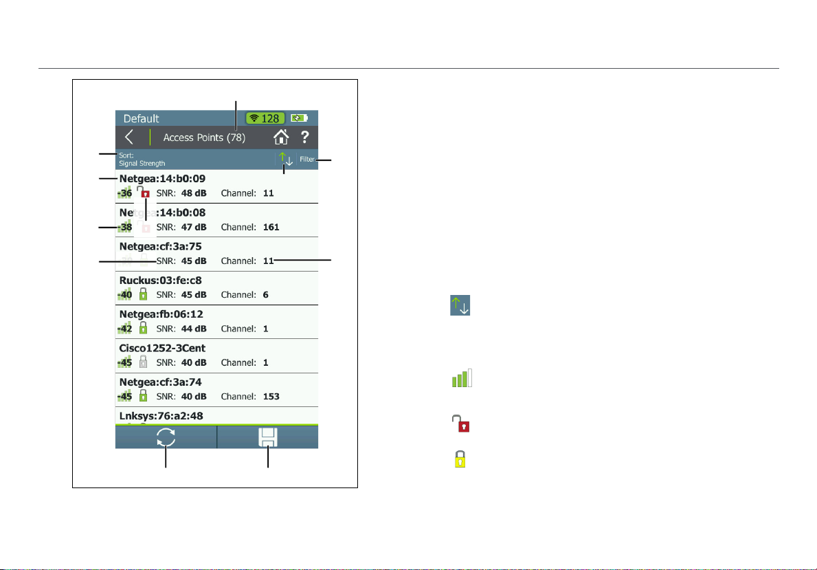
Figure 7. Access Points List
Discovering Networks and Access Points
The Access Points l
that AirCheck G2 has discovered.
ist screen displays all the access points
Access Points (#): The number of APs discovered by the
Tes ter.
Sort (Option Field): This field shows the sort option that
is currently applied. In Figure 7, the sort option applied is
Signal Strength.
Touch the So
points are listed. The value by which the list is sorted
shows prominently for each access point. For example, if
you change to Sort by Client Count, the Access Points
list screen displays the number of connected clients for
each AP, instead of the Channel, as shown in Figure 7.
This is the default.
rt field to change the order in which access
Sort Order Button: These arrows switch the list
order from ascending to descending, and vice versa.
BSSID: Basic Service Set Identifier; The MAC address of
the access point.
Signal Strength: The AP’s signal strength in dBm.
Security status of the AP:
Red open lock: The network does not have security
enabled.
Yellow closed lock: One or more access points use
WEP or Cisco LEAP security protocol. These are less
secure than other protocols.
15
Page 28
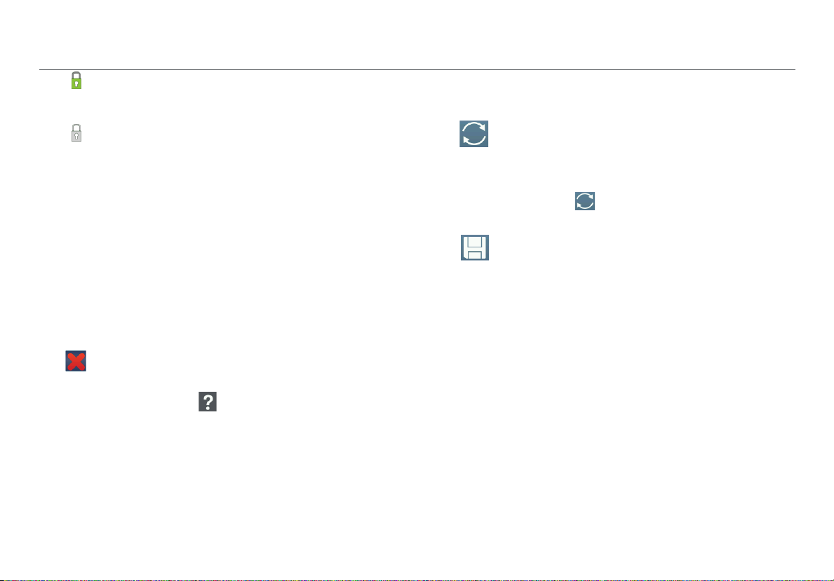
Green closed lock: All access points use security
protocols that are more secure than WEP, for example,
WPA or WPA2.
Gray closed lock: Access points on this network are
using multiple security protocols.
SNR: The AP’s Signal-to-Noise Ratio, a measure of signal
strength relative to noise. The ratio is measured in
decibels (dB).
Filter Button: Touch here to filter for specific AP
characteristics, such as minimum signal strength, 802.11
type, or channel.
NOTE: You can set only one filter at a time. Once a filter is
set, the Access Points screen re-opens. The title of the
screen changes to “Access Points (X of Y)”, such that
X = the number of access points filtered, and
Y = the total number of access points discovered.
This icon appears to the right of the active filter.
Touch the icon to remove the filter.
Touch the Help button on the Filter Access Points By:
screen for more detail about each option.
Channel: The channel used by the AP.
This is also soft field, which changes based on the Sort
option currently applied. For example, if the list is sorted
by Client Count, the number of clients connected to the
access point will appear in this space on the screen.
Discovering Networks and Access Points
For Access Points, this space can also show the SSID,
BSSID, Band, or time since the network was Last Seen.
Refresh: Touch this icon to clear the current
results and restart the current discovery
process.
Caution
Touching the Refresh button will erase
all unsaved test results.
Save: Touch this button to save a session file
containing all discovered networks, APs,
channels, and clients. The session file will also
include all test results for any saved
AutoTests, connection tests, Ethernet tests,
and roaming and range tests. See “Saving
Sessions,” page 69.
16
Page 29
The Access Point Details Screen
Touch an Access Point’s row on the Access Points list screen
to open the Details screen for that AP.
When Group Virtual APs is turned On, multiple SSIDs from
the same AP radio are shown and counted as one AP. If you
touch one of these access points to open its Details, the
Tester displays a list of BSSIDs for you to choose from.
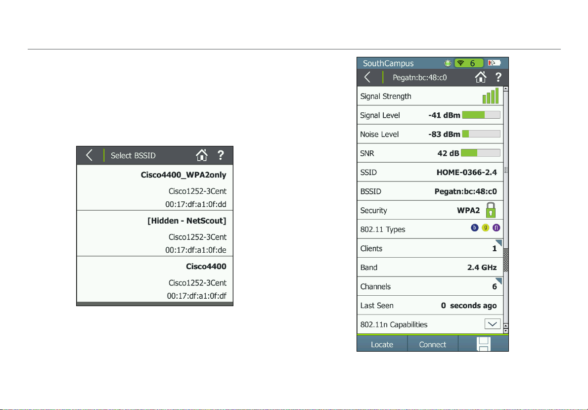
Figure 8. Select BSSID to View AP Details
Discovering Networks and Access Points
17
Figure 9. Access Point Details Screen
Page 30
Screen Title: The AP’s name (BSSID, Cisco AP name, or usercreated alias) is displayed at the top of the AP Details screen.
Signal Strength: The signal strength rating for the AP.
Signal Level: The AP’s signal level in dBm.
Noise Level: The noise level in dBm of the channel used.
SNR: Signal-to-Noise Ratio is a measure of signal strength
relative to noise; an indication of signal quality for a reliable
client’s connection. The ratio is measured in decibels (dB).
SSID: Service Set Identifier; The name of the wireless network
to which the AP is connected.
BSSID: The MAC address of the SSID. The address starts with
a vendor abbreviation prefix, if the prefix is available.
Security status of the AP:
Red open lock: The network does not have security
enabled.
Yellow closed lock: One or more access points use
WEP or Cisco LEAP security protocol. These are less
secure than other protocols.
Green closed lock: All access points use security
protocols that are more secure than WEP, for example,
WPA or WPA2.
Gray closed lock: Access points on this network are
using multiple security protocols.
Discovering Networks and Access Points
802.11 Types: The 802.11 types that the access point
supports:
802.11a: Uses the 5-GHz band.
802.11b: Uses the 2.4-GHz band.
802.11g: Uses the 2.4-GHz band.
802.11n: Can be used in the 2.4 GHz or 5 GHz bands.
802.11ac: Uses the 5-GHz band.
Clients: The number of clients connected to the AP.
Touch this row to open the Clients list screen with the
clients filtered for the selected AP.
Band: The radio band the AP supports.
Channels: The channels that the access point is using.
Touch this row to open the Channels Utilization screen
for the primary channel.
Last Seen: The amount of time that has passed since the
Tester last detected the AP.
802.11n Capabilities: Select the down arrow to expand
for the AP's 802.11n capabilities.
NOTE: The "802.11n Capabilities” are taken from HT
Capabilities in the beacon and included for 802.11n and
802.11ac APs. This field is available only for 802.11n and
802.11ac APs.
18
Page 31

802.11ac Capabilities: Select the down arrow to expand
for the AP's 802.11ac capabilities.
NOTE: The “802.11ac Capabilities” are taken from VHT
Capabilities in the beacon and included for 802.11ac APs.
This field is available only for 802.11ac APs. Because an
802.11ac-only AP reports in its beacon both the HT
Capability and VHT Capability elements, an 802.11ac-only
AP will include both the 802.11ac and the 802.11n
Capabilities fields.
Locate: Touch this button to open the Locate screen and
physically locate an access point.
Connect: Touch this button to connect to the access point
and run a Connection test.
Save: Touch this button to save a session file containing
all discovered networks, APs, channels, and clients. The
session file will also include all test results for any saved
AutoTests, connection tests, Ethernet tests, and roaming and
range tests. See “Saving Sessions,” page 69.
Discovering Networks and Access Points
Troubleshoot: If the Tester Does Not Discover an Access Point or Network
If the Tester cannot hear an access point, consider the
following possible causes:
The Tester cannot hear the access point because you are
far away.
too
The access point does not beacon when the Tester is
listening to the channel t
The Tester cannot hear the access point because the
signal canno
There is too much interference on the channel that the
access point uses
Screen to view the interference from non-802.11 sources
on the channel.
A filter is active on the current screen that is filtering out
one or mor
Other configuration settings do not match the AP
racteristics (band, channel, etc.).
cha
t go through a wall or some other barrier.
. Select Channels from the Home
e APs. Touch
hat the access point uses.
to clear the filter.
19
Page 32

V. VIEWING CHANNEL USAGE
Figure 10. Channels Utilization Screen
Viewing Channel Usage
The Channels Utilization Screen
From the Home Screen, touch Channels to open the
Channels Utilization screen, which provides an overview of
all channels and their APs.
AirCheck G2 calculates and records the average 802.11 and
Non 802.11 channel utilization for each channel per each
scan. Discrete channel utilization measurements begin when
you power on and update with each scan.
Bands: By default, the Tester scans channels on the
2.4 GHz and 5 GHz bands
function, go to Settings > 802.11 Settings > Bands.
. To change the bands for this
Channel Number: The channel corresponding with the
bar graph above it.
Bar Graphs and Dots: The bar graphs show how
much of the channel capacity is used by 802.11
devices (blue) and by non-802.11 interference
(gray). The taller the bar, the noisier the channel.
The dark blue dots in the bar graphs show how
many access points are using the channel as the
primary channel. The numeric value above the
dots also indicates the number of APs discovered
on that channel. In the example to the left,
Channel 11 has six APs.
20
Page 33

NOTES:
Channels that do not have access points can still
w 802.11 usage because of overlap from access
sho
points on adjacent channels.
If there are too many APs t
blue dots, the dots will be truncated to leave space
for the correct number of APs to display above.
o show individual dark
Illegal Channel Number: Invalid channels are
highlighted in red, according to the country selected in
Settings > Location Settings.
Viewing Channel Usage
When you save a session, AirCheck G2 records the average
and the last channel utilizations (i.e., the total utilization,
802.11 utilization, and non-802.11 utilization) for each
channel in the session. These results are sent to AirCheck G2
Manager when you upload the session file.
Touch a channel’s column to zoom in on that channel in the
Select Channel screen.
Refresh: T
results and restart channel scanning.
ouch this icon to clear the current
Caution
Touching the Refresh button will erase all
unsaved test results.
Save: T
containing all discovered networks, APs, channels,
and clients. The session file will also include all test
results for any saved AutoTests, connection tests,
Ethernet tests, and roaming and range tests. See
“Saving Sessions,” page 69.
ouch this button to save a session file
21
Page 34

The Select Channel Screen
The Select Channel screen offers a close-up view of the
selected channel.
Viewing Channel Usage
The channel being selected.
The number of APs on the channel.
The bar graphs show how much of the channel capacity
is used by 802.11 devices (blue) and by non-802.11
interference (gray). The graphs update dynamically.
The next lower and upper adjacent channels (faded).
The left and right arrows for scrolling the lower or higher
channels.
NOTE: When you are on the Select Channel screen, AirCheck
G2 stops scanning channels and remains only on the channel
that is selected.
Touch the middle channel bar or View Details to open the
Channel Details screen for the selected channel.
Figure 11. Select Channel Screen
22
Page 35

The Channel Details Screen
Figure 12. Channel Details Screen
Viewing Channel Usage
The Channel Details screen shows the following detailed
information about the selected channel:
Screen Title: The channel number and frequency of the
channel being monitored.
APs: The number of access points discovered on the channel.
Touch this row to open the Access Points list screen with
the APs filtered for the selected Channel.
NOTE: This field shows the number of physical access
points if Group virtual access points is selected.
Otherwise, individual BSSIDs are shown. See “802.11
Settings,” page 76.
Clients: The number of Wi-Fi clients discovered on the
channel. Touch this row to open the Clients list screen
with the clients filtered for the selected Channel.
Channel Utilization (line graph): Shows 802.11 (blue) vs.
non-802.11 (gray) utilization of the channel over time. The
two horizontal bars below the line graph show in real time
the percentage of 802.11 utilization vs. non-802.11 utilization
of the channel. Very busy channels can make the network
slow or affect connectivity.
Signal Level: The real-time signal level (in dBm) of the
strongest AP signal on the channel.
23
Page 36

VI. DISCOVERING CLIENTS
While the Tester is on, it monitors each channel for client
traffic to discover client devices. To see these clients, touch
the Clients row on the Home Screen.
NOTES: The Tester is only able to update the client’s
information when the client transmits data at the same time
that the Tester is monitoring the channel that the client uses.
To collect client information more quickly, go to Settings
> 802.11 Settings, and enable only one band, which
decreases the number of monitored channels.
The Client List Screen
The Clients list screen provides an overview of the Wi-Fi
clients discovered in your environment. It shows the
following information for each of the clients:
Clients (#): The numeric value in parentheses indicates
the number of active clients discovered.
Sort (Option Field): This field shows the sort option that
is currently applied. In Figure 13, the sort option applied
is MA
C Address.
Discovering Clients
Figure 13. Clients List Screen
24
Page 37

Touch the Sort field to change the order in which clients
are listed. The value by which the list is sorted shows
prominently for each client. For example, if you change
to Sort by 802.11 Type, the Clients list screen displays
the 802.11 type icons next to each client, instead of the
AP it is connected to, as shown in Figure 13.
Sort Order Button: These arrows switch the list
order from ascending to descending, and vice versa.
MAC: The MAC address of the client. The address starts
with a vendor abbreviation prefix, if the prefix is
available.
The client name can be either (1) MAC colon
NOTE:
format, e.g., 00:11:22:33:44:55 or (2) OUI compact colon
format, i.e., Vendor:33:44:55. You can set or change the
client display format from Settings > 802.11 Settings
> MAC Address Format.
(Signal Strength): The client’s signal strength. The
color of the bars and the numeric value change with the
fluctuation of signal strength.
actual
Security status of the AP:
Red open lock: The network does not have security
enabled.
Yellow closed lock: One or more access points use
WEP or Cisco LEAP security protocol. These are less
secure than other protocols.
Discovering Clients
Green closed lock: All access points use security
protocols that are more secure than WEP, for example,
WPA or WPA2.
Refresh: Touch this icon to clear the current
results and restart the scan.
Caution
Touching the Refresh button will erase all
unsaved test results.
Save: Touch this button to save a session file
containing all discovered networks, APs, channels,
and clients. The session file will also include all test
results for any saved AutoTests, connection tests,
Ethernet tests, and roaming and range tests. See
“Saving Sessions,” page 69.
Filter Button: Touch here to filter for specific client
characteristics, such as AP name, security type, or time
since the client was last seen.
NOTE: You can set only one filter at a time. Once a filter is
set, the Clients screen re-opens. The title of the screen
changes to “Clients (X of Y)”, such that
X = the number of clients filtered, and
Y = the total number of clients discovered.
This icon appears to the right of the active filter.
Touch the icon to remove the filter.
25
Page 38

Touch the Help button on the Filter Clients By:
screen for more detail about each option.
Channel: The channel which a client is using. This field is
blank for probing clients.
AP: Shows the name of the AP the client is associated
with. This field is blank for probing clients.
This is also soft field, which changes based on the Sort
option currently applied. For example, if the list is sorted
by 802.11 Type, the 802.11 type icons will appear in this
space on the screen, instead of the AP name.
For Clients, this space can also show the SSID, AP BSSID,
Band, or time since the network was Last Seen.
To open the Details screen for a client, touch its row.
Discovering Clients
The Client Details Screen
The Client Details screen shows the following detailed
information about the client you have selected:
Screen Title: The client’s full MAC address (e.g.,
00:11:22:33:44:55) or OUI compact colon format (e.g.,
Vendor:05:3f:76). See “802.11 Settings,” page 76.
Signal Strength: The client's signal strength in four bars. The
color of the bars changes in real time to reflect the actual
fluctuation in the client's signal strength.
Signal Level: The client's actual signal level in dBm and a
horizontal bar indicating the rating.
SSID: The SSID with which the client is associated. The field
will be blank when no client-AP association is detected.
AP Name: The name of the AP with which the client is
associated. The field will be blank when no client-AP
association is detected.
AP BSSID: The BSSID of the AP with which the client is
associated. The field will be blank when no client-AP
association is detected.
Connection Rate: The speed in Mbps of the last frame seen
from the client.
26
Page 39
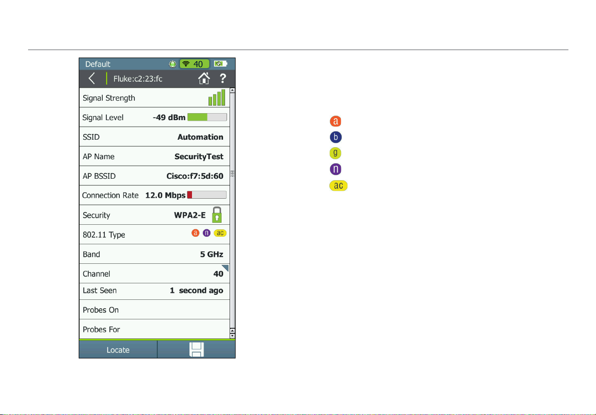
Discovering Clients
Security: Shows the security type for the client-AP
connection. The field will be blank if the client is not
associated with an AP, is using an ad-hoc connection, or its
security standard is unknown.
802.11 Type: The 802.11 type that the client is using:
802.11a: Uses the 5-GHz band.
802.11b: Uses the 2.4-GHz band.
802.11g: Uses the 2.4-GHz band.
802.11n: Can be used in the 2.4 GHz or 5 GHz bands.
802.11ac: Uses the 5-GHz band.
Band: Shows the WiFi band of the client connection.
Channel: The primary channel the client is using. Select this
field to open the Channel Details screen for more
information about this primary channel.
Last Seen: Shows the time when the last packet from the
client was detected.
Probes On: Shows the band and channels from the last
probe request. The field is populated only for probing clients;
it is blank for associated clients.
Probes For: Shows the SSID from the last probe request. The
field is populated only for non-associated clients; it is blank
for associated clients.
Figure 14. Client Details Screen
27
Page 40

Locate: Touch this button to open the Locate screen and
begin locating the client.
Discovering Clients
Troubleshoot: If the Tester Does Not Discover a Client
Save: Touch this button to save a session file containing
all discovered networks, APs, channels, and clients. The
session file will also include all test results for any saved
AutoTests, connection tests, Ethernet tests, and roaming and
range tests. See “Saving Sessions,” page 69.
In some situations, the Tester will not discover a client
because of the following:
The wireless card in the client is disabled.
The Tester cannot hear the client because you are too far
from the client.
away
The Tester cannot hear the client because the signal
t go through a wall or some other barrier.
canno
There is too much interference on the channel that the
client uses
non-802.11 sources on the channel.
The Tester does not scan the band that the client uses.
See the set
The client does not transmit when the Tester is listening
to the channel t
A Fil
one or more clients. Touch to clear the filter.
. Select Channels to see the interference from
ting in Settings > 802.11 Settings.
hat the client uses.
ter is active on the current screen that is filtering out
28
Page 41

Using AutoTest to Diagnose Your Network Health
VII. USING AUTOTEST TO DIAGNOSE YOUR NETWORK HEALTH
AutoTest automatically checks the health of your network by
examining Air Quality for utilization and interference and
Network Quality for the SSIDs that have been configured for
AutoTest. See “AutoTest Settings,” page 81.
When AutoTest runs, the test result fields turn green, red, or
yellow to indicate the status or rating of the result.
For example, in Figure 15, the 802.11 Utilization test has
passed, the Non 802.11 Utilization and Co-Channel
Interference has received a warning, and Adjacent Channel
Interference has failed. These ratings are controlled by the
Thresholds configured in the AirCheck G2’s Settings. See
“Adjusting the Test Thresholds,” page 47.
To run an AutoTest, touch the AutoTest field on the Home
Screen. The AutoTest results screen opens and results are
displayed as each test finishes.
Touch the down arrows next to each row to view specific
measurements.
AutoTest Air Quality
The Air Quality measurements include 802.11 Channel
Utilization, Non-802.11 Channel Utilization, Co-channel
Interference, and Adjacent Channel Interference.
Figure 15. AutoTest Air Quality Results Screen
Touch the Restart
Touch the Save icon to save the results as a session file.
button to clear results and start a new test.
29
Page 42

Using AutoTest to Diagnose Your Network Health
802.11 Utilization
The 802.11 Channel Utilization results include the top three
channels in each band (2.4 GHz and 5 GHz) with the highest
802.11 utilization. The channels are displayed with their
measured utilization percentage and rating of Pass,
Warning, or Fail, based on the 802.11 Interference
threshold.
Non-802.11 Utilization
The Non-802.11 Channel Utilization results include the top
three channels in each band (2.4 GHz and 5 GHz) with the
most non-802.11 interference, e.g., noise.
The channel utilization percentage is displayed along with a
rating symbol: Pass, Warning, or Fail, based on the
non-802.11 Interference threshold.
The channel usage will vary depending on the time of day,
based on the number of clients connected to the network,
the amount of interference from devices, such as
microwaves or video cameras, etc.
Figure 16. 802.11 Channel Utilization Results
30
Page 43

Figure 17. Air Quality Co-Channel and Adjacent Channel
Interference Results
Using AutoTest to Diagnose Your Network Health
Co-Channel Interference
The Co-Channel Interference results display the top three
channels in each band (2.4 GHz and 5 GHz) with the highest
number of APs that exceed the minimum AP signal level
threshold in the same channel.
This measurement is independent of SSIDs and solely looks
at the number o
quality. It accounts for 40-MHz and 80-MHz channels in the
5-GHz band by counting an AP on its primary and each
secondary channel.
A Pass, Warning, or Fail icon is also displayed for
each channel.
f APs using the same channel and their signal
Adjacent Channel Interference
The Adjacent Channel Interference results display the top
three channels in the 2.4-GHz band in which APs may
experience Adjacent Channel Interference. For each channel
on which at least one AP is found, the Tester counts how
many APs are operating on other channels that overlap with
that channel. It accounts for 20-MHz and 40-MHz channels in
the 2.4-GHz band. The Adjacent Channel Interference
measurement does not apply to the 5-GHz band.
Pass, Warning, or Fail icon is also displayed for
A
each channel.
31
Page 44
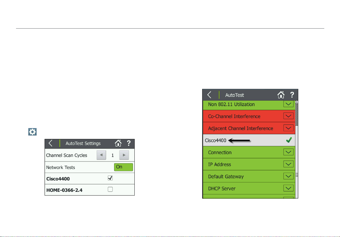
AutoTest Network Tests
The Network Test measurements check for network
availability; the existence of interference from access points
using the same channel, which may cause network slowness;
AP use of consistent security methods for a network; and the
ability to connect and use the network (access to services,
other devices).
How to: Run Network Quality Tests as part of AutoTest
1
To see these tests, you must enter and save the security
credentials for the network or AP you wish to test.
See “Entering Network Security
2
You must also select the networks you want tested
during AutoTest from the AutoTest Settings screen
( Settings > AutoTest Settings).
Credentials,” page 41.
Using AutoTest to Diagnose Your Network Health
Once the SSID and security credentials have been entered,
AutoTest runs Network Tests for each network selected.
In the example shown in Figure 18, security for the SSID,
“Cisco4400,” has been configured and added to the Profile,
and the network is selected in AutoTest Settings.
Network Test results are reported on the AutoTest results
screen below the Air Quality test results. In Figure 19, the
Network test for “Cisco4400” has run and passed.
Figure 18. AutoTest Settings Screen
3
Touch AutoTest from the Home Screen.
Figure 19. AutoTest Results Screen
32
Page 45

NOTE: When you connect to a network, the Tester usually
connects through the access point that has the highest
Signal-to-Noise Ratio. If the network includes secure and
unsecured access points and security credentials are
available, the Tester tries to connect to the secure access
point that has the highest Signal-to-Noise Ratio. Some
networks use a controller that connects you to the access
point that has the least amount of traffic.
Connection Test Results
The Connection test results indicate whether or not you can
connect to an AP for the configured network at your current
location. The Connection field turns green if the connection
was successful and red if the connect was unsuccessful.
Touch the down arrow to the right of Connection to view
high level connection diagnostics. These results also receive a
rating based on whether the individual test was successful, or
based on how measurements compare to the configured
thresholds: Pass or Success (green), Warning (yellow),
or Fail (red)
Connect to AP: Indicates whether the Tester was able to
connect to the AP.
Authenticate: Indicates whether the Tester was able to
authenticate with the AP.
Exchange packets with AP: Indicates whether the Tester
received packets back from the AP.
Using AutoTest to Diagnose Your Network Health
Figure 20. AutoTest Network Connection Test Results
Network Coverage: Indicates the number of access points
the Tester detected that are supporting the network. This
field also displays a rating symbol based on the Network
Coverage threshold.
33
Page 46

Co-channel Interference: Displays the number of APs that
exceed the minimum signal strength threshold with primary
or secondary channels on the same channel on which the
Tester connects to the network.
Security: Indicates whether all access points use security
protocols that are more secure than WEP, for example, WPA
or WPA2.
% of Max TX Rate: The physical transmission rate as a
percentage of the maximum rate possible.
Retry Rate: The percentage of packets the AirCheck G2
Tester had to send out again for proper transfer.
BSSID: The MAC address of the access point.
AP Name: The name of the AP to which the Tester is
connected. The address starts with a vendor abbreviation
prefix, if the prefix is available.
Channel: The channel the AP uses.
Other Connection Results: The rest of the results under
Connection provide exact values for the average, minimum,
and maximum Signal, Noise, SNR, and TX Rate.
IP and Target Test Results
Touch the arrows to the right of each field to expand or
collapse test details:
Using AutoTest to Diagnose Your Network Health
Figure 21. AutoTest Network Test IP and Test Targets
IP Address: Indicates whether or not an IP was successfully
obtained via DHCP or if a static IP is configured.
Default Gateway: Indicates whether or not the configured
gateway could be successfully pinged.
DHCP Server: Indicates whether or not the DHCP service
could be successfully pinged.
DNS1 and DNS2: Indicate whether the DNS server could be
successfully pinged.
34
Page 47

Targ et s: Indicates whether or not these user-configured test
targets could be successfully reached via Ping or TCP Port
Open Test. The default target is www.google.com, but you
can add and edit tests targets from the Settings > Test
Targets. See “Locating an Access Point or a Client,” page 55.
Link-Live Upload: Indicates whether the AirCheck G2 Tester
was able to upload the AutoTest results to a Link-Live
account. See “Getting Started in Link-Live Cloud Service,”
page 38.
Using AutoTest to Diagnose Your Network Health
35
Page 48

VIII. TESTING ETHERNET FOR ACCESS POINT BACKHAUL
The Ethernet Test verifies key connectivity parameters for the
wired link to an access point.
To configure the Ethernet test, see “Ethernet Settings” on
page 78.
The Ethernet Test Results Screen
The results fields report high-level Pass (green) or Fail (red)
results of the test components. Select the down arrows
to the right of each field to view detailed information.
PoE: Indicates whether or not PoE capabilities are detected
on the current link, including the measured voltage in
parentheses if present. NOTE: You can disable the PoE test in
Ethernet Settings.
Link: Indicates whether or not a Layer-2 Ethernet link is
established. The field turns green if a link was successfully
established or red if no link could be established.
Port: Displays the switch name, model, MAC address, IP
address, port number, and VLAN IDs. The information is
gathered from switch port info packets (CDP, EDP, and LLDP).
NOTE: T
packet (LLDP, CDP, or EDP) on the wire after it establishes
link and uses this to populate the Port information. If it is
capable of hearing these packets from more than one
Figure 22. Ethernet Test Screen
he AirCheck G2 listens for the first switch info
Testing Ethernet for Access Point Backhaul
36
Page 49

source, it will display the first one it receives, which may
not always be from its link partner.
Furthermore, when AirCheck G2 is not linked directly to a
managed switch that emits these types of packets, but is
instead linked with another switch in between, it will not
reliably receive this switch port information. Most of
these managed switches send these packets as soon as
they detect link establishment, which they cannot do in
this case. However, they may retransmit this information
periodically, which AirCheck G2 will receive and display if
it can.
NOTE: The switch name may be truncated if it exceeds
the length of the field.
DHCP: Indicates whether or not a DHCP address was
obtained.
Default Gateway: Indicates whether or not AirCheck G2 can
ping the default gateway.
Network: Indicates whether or not AirCheck G2 can
successfully reach a user-defined network target via Ping or
TCP Port Open test. This function can verify connectivity to a
wireless controller, for example. See “Ethernet Settings,”
page 78.
Link-Live: Indicates whether or not test results were
successfully sent to the Link-Live Cloud Service.
Testing Ethernet for Access Point Backhaul
Stop: While the test is running, select this button to stop the
test.
Restart: After the test has completed (or you've stopped the
test), select the Restart button to start a new test.
DHCP Log: Select this button to view the test log.
Save: Touch this button to save a session file containing
all discovered networks, APs, channels, and clients. The
session file will also include all test results for any saved
AutoTests, connection tests, Ethernet tests, and roaming and
range tests. See “Saving Sessions,” page 69.
37
Page 50

IX. COMPANION SERVICES
Companion Services
These two free services enhance your testing, analysis, and
documentation capabilities with the AirCheck G2 Tester.
Getting Started in Link-Live Cloud Service
This online service, once set up, automatically uploads and
saves AutoTest and Connection test results from the Tester
any time the it is connected to the internet. In the Link-Live
Cloud Service, you can comment on test results, label and
organize your switch and cable set up, monitor data from
multiple testing devices as they come in, and document
completed jobs.
To start, create a user account at Link-Live.com
Next, you must Claim the Tester to the cloud service.
How to: Claim the AirCheck G2 to Link-Live
1
After creating a user account, sign in to Link-Live Cloud
Service.
2
Once you are signed in, click
the Units drop-down menu
at the upper right.
3
Click Claim, and select the
AirCheck G2 image.
.
4
Follow the on-screen instructions to finish claiming.
5
Click “Listen” in Link-Live before you touch “Claim” on the
Tes ter.
See “Link-Live Settings,” page 84.
Once your AirCheck G2 Tester is claimed in Link-Live, test
results will upload automatically after you have run a test
and successfully connected to the internet. The Link-Live
Upload field on the AutoTest and Connection test results
screens indicates whether the test results were successfully
sent to Link-Live.
Figure 23. Successful Link-Live Upload Field
If no connection is available, the Tester will queue up to 10
tests before overwriting previous results.
You can also configure uploading and notification settings on
the Link-Live Cloud Service web site. For more information
about Link-Live, click Support > Questions at the top right of
the Link-Live web page at Link-Live.com
.
38
Page 51

Getting Started with the AirCheck G2 Manager PC Application
To fully utilize all of your Tester’s capabilities, use the
AirCheck G2 Manager computer application for the following
activities:
Upgrade the AirCheck G2 Tester firmware.
Update the AirCheck G2 Tester’s Vendor MAC Prefix file.
View measurement results saved as session files.
Generate reports from session files.
Set up the AirCheck G2 Tester configuration by creating
ofiles.
Pr
Configure security credentials for the n
containing any key devices that you are pinging.
Transfer Profiles with saved settings to the Tester.
Transfer screen capture images from the AirCheck G2
ste r to a PC.
Te
Download the AirCheck G2 Manager software from Link-Live
at https://app.link-live.com/downloads.
etwork(s)
Companion Services
Figure 24. Session Data > Networks in AirCheck G2
anager
M
After downloading and installing the application, connect
our AirCheck G2 Wireless Tester to the PC using the supplied
y
Micro Type B to USB cord.
NOTE: Only Micro Type B cables can be used to connect the
AirCheck G2 to a PC. USB on-the-go (OTG) cables will not
work properly.
The AirCheck G2 Manager online Help contains
more instructions for using the application.
See “Managing Profiles and Sessions on a PC using
AirCheck G2 Manager,” page 71.
39
Page 52

X. CUSTOMIZING THE TESTER FOR YOUR NETWORK
This chapter describes how to adjust the Settings that
e essential for setting up the Tester for your network and
ar
running in-depth performance tests. For a description of all
other settings, see “All AirCheck G2 Settings” on page 74.
To change the settings on the Tester, touch the Settings
button from the Home Screen.
Help: Touch this icon to open the embedded Help topic
with a description of the current screen.
Changing the Location Settings and Language
The Location Settings configure the Tester to show illegal
channels for the selected country in red text. See “The
Channels Utilization Screen,” page 20.
How to: Change the location settings
1
In the Settings menu, touch Location Settings.
2
Select your country from the drop-down menu.
3
Touch Apply.
How to: Change the language on the Tester
1
In the Settings menu, touch Device Settings.
Figure 25. Settings Menu Screen
2
Touch Language.
Customizing the Tester for your Network
40
Page 53

3
Select your language from the list of those available.
4
Touch Apply.
The Tester will reboot and then show the selected
language.
Entering Network Security Credentials
There are three methods for entering and saving network
and AP security credentials:
From the Tester’s Ne
screen
In the Tester’s
In AirCheck G2 Manager’s Pr
How to: Enter credentials from the Networks or Access Points list
If you select a discovered network or AP from the Networks
or Access Points list, you will not need to enter the SSID.
1
From the Home Screen, touch Networks or Access
Points.
2
Touch the row of the relevant network or AP to open the
details screen.
3
From the network or AP details screen, touch the
Connect button at the bottom of the screen. See Figure
26.
twork or Access Point Details
Settings menu
ofile Setup menu
Customizing the Tester for your Network
Figure 26. Network Details Screen
4
If the network or AP is secured, the Configure screen
opens; enter the password on the configuration screen.
41
Page 54

5
Click the Apply button at the bottom of the screen.
The Tester will run a Connection test. Afterwards, the
credentials for the Network or AP are retained in the unsaved
Profile, which is denoted with an asterisk (*) (shown in Figure
27).
How to: Enter credentials in the Settings menu
1
From the Home Screen, touch the Settings button.
2
Select Networks or Access Points.
Figure 27. Configured Networks in Settings
3
On the Networks or Access Points settings screen, touch
Add Network or Add AP. See Figure 27.
4
Enter the necessary SSID (or BSSID) and security
credentials.
Customizing the Tester for your Network
5
Leave DHCP set to On, or configure a Static IP Address
as needed:
To use DHCP, leave the setting On. This is the default.
To configure a Static IP Address, toggle the DHCP
switch to Off, and enter the appropriate server
addresses.
6
Touch Apply to add the credentials to the Profile. You
should see your new network or AP’s name listed in
Settings > Networks, as shown in Figure 27.
How to: Enter credentials in AirCheck G2 Manager
NOTE: See the AirCheck G2 Manager Help for
additional instructions.
1
Connect the Tester to a PC with AirCheck G2 Manager
installed.
2
Open the AirCheck G2 Manager application.
3
Select Profile Setup from the left side navigation menu.
4
Edit a Profile:
If necessary, transfer the “Default” Profile from
AirCheck Pr
the right pane by dragging and dropping the Profile
name. Then, double-click the Profile name, or click the
pencil icon
You can also click the icon
ofiles, in the left pane, to Local Profiles in
to edit the Profile’s configuration.
to “Create a new Profile.”
42
Page 55

5
Enter the required configuration information, and click
Save.
Once added, the network or AP name will appear in the
Settings menu on the Networks or Access Points screen
as shown in Figure 27.
NOTE: Notice that the Profile name at the top left of the
screen has an asterisk because the Profile has not been
saved with the new credentials. Once you enter security
credentials for an SSID (or multiple SSIDs), save them to a
Profile to avoid losing these settings if another Profile is
loaded or if the Tester firmware is updated.
Customizing the Tester for your Network
Using Profiles to Manage Settings and Security Credentials
Profiles are files that save configuration settings for the
Tester and security credentials for networks and APs, which
let the Tester connect and perform roaming tests and
connectivity tests to DNS servers, DHCP servers, the default
router, and network targets. Profiles also include the
following information:
All 802.11 settings (For example, Enable 2.4-GHz band
and Enable 5-GHz band)
AutoTest settings
Ethernet test settings
IP addresses used for ping or TCP Port Connect tests
Location and Language
Thresholds for the colored bar graphs and Pass,
Warning, and Fail ratings
Profiles can be password protected so that unauthorized
users cannot use the Tester to connect to secure networks or
access network security credentials on the AirCheck G2
Manager PC application.
The AirCheck G2 Tester’s Home Screen shows the name of
the Profile the Tester is using at the top left. The name shows
an asterisk (*) if you have changed a setting on the Tester
since you last saved the Profile.
43
Page 56

You can create and edit Profiles on both the AirCheck G2
Tester and in AirCheck G2 Manager on a personal computer
(PC).
How to: Save the current settings as a Profile on the AirCheck G2 Tester
Multiple Profiles can be saved on the Tester, but only one
Profile at a time can be active.
1
From the Home Screen, touch the Settings button.
2
Then, select Profiles.
Figure 28. Setting > Profiles Menu
3
Touch Save or Save as.
Customizing the Tester for your Network
To save the Profile with the current name (shown at
the top left
ask if you want to overwrite the existing Profile name
before saving.
To save the Profile with a new name:
a. Select Save As.
b. Touch Name
a new name.
c. Touch DONE when finished.To save a Secured
Profile, change the default Type from Open to
Secured, and enter a password.
of the screen), press Save. The Tester will
Figure 29. Profiles > Save As
and use the soft keyboard to type in
44
Page 57

To save a Secured Profile:
a. Touch the down arrow to change the default Ty
from Open to Secured.
b. Touch Password to enter a password on the soft
keyboard.
Caution
Ensure that you enter the password as you intend it.
Touch the open lock icon to double-check that it is
correct. If you enter the password incorrectly here, or
forget the password, you may not be able to access
your Secured Profile again.
c. Touch DONE when you finish entering the
password.
Touch Apply when you fini
sh configuring the Profile.
pe
Customizing the Tester for your Network
How to: Transfer a Profile from a PC to the Tester
NOTE: See the AirCheck G2 Manager Help for
additional instructions.
1
Use the Profile Setup in AirCheck G2 Manager to make a
Profile.
2
Connect the Tester to the PC using the USB cable
supplied.
3
Wait for AirCheck G2 Manager to show a green
“Connected” indicator at the top left.
4
In AirCheck G2 Manager, drag and drop the Profile name
from the right panel, “Local Profiles,” to the left panel,
“AirCheck G2 Profiles” to transfer the Profile to the
Tes ter.
NOTE: You must Load the Profile on the Tester before
you can use it.
How to: Load a Profile that is saved in the AirCheck G2 Tes ter
1
From the Home Screen, touch the Settings button.
2
Touc h Profiles.
3
Touch Load, and select a Profile name from the list.
4
Touch Apply.
5
Enter the password if the Profile is secured.
45
Page 58

The Profile loads and the Tester returns to the main Settings
menu.
How to: Delete a Profile on the Tester
1
Select Settings > Profiles.
2
Select Delete.
3
Select the Profile you want to delete.
NOTE: You cannot delete the currently active Profile.
4
Touch Apply.
5
Confirm that you want to delete by touching Yes.
Customizing the Tester for your Network
46
Page 59

Customizing the Tester for your Network
Adjusting the Test Thresholds
The AirCheck G2 Tester illustrates the status of your network
using red, green, and yellow colors in the following ways:
Colored bar graphs:
Pass/ Warning/ Fail ratings
Other test result fields that turn red, gre
for example, in AutoTest results:
Figure 30. AutoTest Air Quality Results Screen
The colored ratings for test results on the AirCheck G2 are
based on Thr
with the configured thresholds to determine whether a result
receives a Pass, Warning, or Fail rating. These ratings are set
by default on the AirCheck G2 Tester, but you can adjust
them for your own network testing needs.
esholds. The Tester compares measured data
en, or yellow,
How to: Change the test thresholds on the Tester
1
Touch Settings on the Home Screen.
2
Select Thresholds.
Figure 31. Thresholds Screen
3
Touch the and buttons to increase or decrease the
measurements that will receive a rating of Pass (gre
or Fail (red). The range in between will receive the
Warning (yellow) rating.
For a list of all Thresholds, see “Thresholds” on page 79.
en)
47
Page 60

XI. VERIFYING CONNECTIVITY AND COVERAGE
Verifying Connectivity and Coverage
The Connect to Network and Connect to AP tests let you
verify connectivity at specific locations in your network. Use
these tests to verify the operation of the following wireless
network functions:
Clients can connect to the network.
Clients have access to network services (for example,
DHCP, DNS, and routers).
Clients can communicate with other devices in a
reasonable amount of time.
The range for client connections is satisfactory.
The tests also measure performance parameters that can
show you if the network has a problem.
NOTES:
The Connect to Network and Connect to AP tests
accessed from the Networks and Access Points Details
screens are similar to the Connection tests that run
during AutoTest for configured SSIDs. Both tests verify
connectivity. However, the Connect to Network or AP
tests connect to one SSID at a time, allow you to enter
network security credentials if they are not preconfigured, and act as precursors to conducting roaming
and range tests.
When you connect to a network, the Tester usually
connects through the access point that has the highest
Signal-to-Noise Ratio. If the network includes secure and
unsecured access points and security credentials are
available, the Tester tries to connect to the secure access
point that has the highest Signal-to-Noise Ratio. Some
networks use a controller that connects you to the
access point that has the least amount of traffic.
You may not be able to connect to a hidden SSID or
network until it can be resolved with a probe request or
client connection.
Defining Ping and TCP Port Open Test Targets
To test connectivity to specific devices or application servers,
you can configure them as Test Targets for ICMP Ping or TCP
Port Open tests. The Tester will run these configured tests
during all network or AP Connection tests, including
AutoTest.
NOTE: Up to 10 test targets can be configured and saved as
part of a Profile on the AirCheck G2 Tester.
48
Page 61

How to: Add a new network Test Target
1
Touch Settings on the Home Screen.
Figure 32. Settings > Test Targets Screen
2
Select Test Ta rgets, and then, touch Add Test Target.
Verifying Connectivity and Coverage
Figure 33. Configure Target Screen
3
Touch Target to enter an IP address or host name. Select
either the URL Keyboard or IPv4 Address Keyboard, and
type in the address.
NOTE: If you specify a Ping test to a web server
that does not respond to Ping requests, the test may fail
even if the target is reachable.
4
Touch DONE.
5
Choose a Test Type: ICMP Ping or TCP Port Open. Touch
the down arrow
NOTE: The default test type is ICMP Ping. If you select TCP
Port Open, then you may change the default Port by
touching, Port to open the TCP Port screen, and entering
the TCP port number.
6
Touch Apply to add the test target. (In Figure 33, the user
has added www.netscou
NOTE: W
Targets, the target is automatically added to AutoTest and
Connect to Network/AP tests. See Figure 37.
hen you add a test target in Settings > Test
to switch between them.
t.com.)
target
49
Page 62

Running a Connect to Network or Connect to AP Test
1
From the Home Screen, touch Networks or Access
Points.
2
Touch the row of the relevant network or AP to open its
Details screen.
3
From the Network or AP details screen, touch the
Connect button at the bottom of the screen to open the
Connect to Network or Connect to AP screen,
see Figure 35.
When you press Connect,
If an AP supports more than one network, a screen
appears with a list o
SSID to which you want to connect.
f SSIDs, allowing you to select the
Verifying Connectivity and Coverage
If the network or AP is secured and you have no
configured its credentials in the current Profile, the
configuration screen will open. Enter the password,
and touch Apply to connect.
If the network or AP is not secure, or if its credentials
e already saved in the Profile, the connection test
ar
starts.
The results are displayed as they become available.
t
Figure 34. The Connect to AP Test Screen (In Progress)
When a connection test finishes, the Tester stays connected
to the AP until you touch the Back or Home button.
50
Page 63

Reviewing Connect to Network or AP Results
The results fields on this screen change color to indicate the
success or failure of each portion of the Connect to Network
or AP test.
SSID: The network's SSID.
BSSID: The MAC address of the access point that the Tester
uses for the connection.
Link Uptime: The length of time during which the link has
been established.
Connection Established
To expand or collapse the details for a test step, press the
arrow button.
Connect to AP: Indicates whether the Tester was able to
connect to the AP.
Authenticate: Indicates whether the authentication
steps passed.
Exchange packets with AP: Indicates whether the
Tester received packets back from the AP.
IP Address
IP Address: The IP address of the currently established
connection.
Verifying Connectivity and Coverage
Figure 35. The Connect to AP Test Results
51
Page 64

Targ et Tests
Default Gateway: Indicates whether or not the configured
gateway could be successfully pinged.
DHCP Server: Indicates whether or not the DHCP server
could be successfully pinged.
DNS1 and DNS2: Indicate whether the primary (DNS1) and
secondary (DNS2) DNS servers could be successfully pinged.
(User-Definable) Targets: Indicates whether or not the userconfigured test targets could be successfully pinged or
reached with a TCP Port Open test.
NOTE: The default target is www.google.com, but you
can add and edit test targets. See “Defining Ping and
TCP Port Open Test Targets,” page 48.
Link-Live Upload: Indicates whether the Tester was able to
upload the current test results to a Link-Live account. See
“Getting Started in Link-Live Cloud Service,” page 38.
PHY Data Rate: The highest measured physical transmit
data rate.
NOTE: If the Tester roams to a new AP after a connection
test has completed, a data rate of -- will be displayed.
The -- indicates that AirCheck G2 is not currently
transmitting Wi-Fi data and a data rate cannot be
obtained.
Verifying Connectivity and Coverage
Figure 36. Completed AP Connect Test Screen
Signal Level: T
Noise Level: The measured real-time noise level.
SNR: The measured real-time signal-to-noise ratio.
he measured real-time signal level.
52
Page 65

Reviewing User-Defined Test Target Results
While the Connection test is still running, the Target Test
fields displays:
Once the test finishes, the field turns green if successful.
Verifying Connectivity and Coverage
DNS Name: Network name and access point name for the
ping target.
IP Address: IP address for the ping or the TCP Port Connect
target.
Pings Sent: The number of pings the AirCheck G2 Tester sent
to the target.
Pings Returned: The number of pings the Tester received
back from the test target.
Pings Lost: The number of pings that were not answered.
Avg, Min, and Max Ping Rsp Time: The average, minimum,
and maximum time in milliseconds for the test target to
return a ping.
Press the Log button to see details about the connection
procedure.
Figure 37. Connection Test Target Results
53
Page 66

Next Steps
After running Connection tests, the AirCheck G2 Tester
displays the buttons to start a Network Roaming Test or AP
Range Test.
On the completed Connect to AP scr
press Ra
See “Performing an Access Point Range Test,” page 66.
On the completed Connect to Network test sc
(Figure 38), press Roaming Test to begin a roaming test
for the network. See “Performing a Network Roaming
Test,” page 62.
Press the Lo
procedure.
Press the
session file. See “Saving Sessions,” page 69.
nge Test to begin a range test for the AP.
g button to see details about the connection
Save button to save the test results to a
een (Figure 36),
reen
Verifying Connectivity and Coverage
Figure 38. Completed Network Connect Test Screen
54
Page 67

XII. LOCATING AN ACCESS POINT OR A CLIENT
Locating an Access Point or a Client
The AirCheck G2 can use either the three internal antennas
or the optional external antenna (sold separately) to locate
APs and clients. In areas that have many rooms, for example
in schools and hospitals, use the internal antennas to locate
access points.
In large, open areas, the optional external antenna can help
you locate access points or clients more quickly.
See “Using the External Directional Antenna,” page 59.
The AirCheck G2 Tester can use either the external antenna
or the internal antennas, but not both at the same time.
When you are on the Locate screen, if AirCheck G2 has
sensed NETSCOUT’s external antenna being connected, the
switch is set to the external antenna. When the external
antenna port is turned off, AirCheck G2 automatically
switches to the internal antenna. Otherwise, the Locate
function defaults to the internal antenna.
How to: Locate an AP or Client
1
To locate an access point: Go to the Access Points list
screen, and select the access point you want to locate to
open the Access Point Details screen (Figure 9).
To locate a client: From the Home Screen, touch Clients,
and select the client you want to locate to open the
Client Details screen (Figure 14).
2
Press Locate.
Figure 40 shows the Locate Access Point screen.
Figure 41 shows the Locate
3
Divide the area you want to search into four sections, as
shown in Figure 39. Go to one corner of the area.
4
Make a note of the signal strength.
5
Go to the other three corners of the area, and make a
note of the signal strength at each corner.
6
Go to the section that has the strongest signal.
7
Repeat steps 3, 4, 5, and 6 again until you find the access
point or client.
NOTES:
If you do not find the access point or client, look on the
loor above or below you.
f
If you cannot find a client, and the client shows a
connection to the net
the client used, then look for the client.
Client screen.
work, first find the access point that
55
Page 68

How to: Search using the Internal Antennas
Make a note of the signal
strength.
?
Go to the first corner of the
section that had the strongest
signal.
Locating an Access Point or a Client
Figure 39. Search Pattern for the Omni-directional Antennas in the Tester
56
Page 69

Locating an Access Point or a Client
The Locate AP Screen
The following information shows on the Locate Access Point
screen:
Screen Title: Shows the AP’s SSID. The address starts with a
vendor abbreviation prefix, if the prefix is available. See “How
to: Load the latest list of vendor prefixes into the Tester,”
page 73.
BSSID: The AP's BSSID.
Last Seen: The time elapsed since the AP was last detected.
Signal Strength Meter: Visually displays the AP's real-time
signal level reading.
Signal Strength Line Graph: Visually displays AP's signal
level over time and the highest signal strength recorded (high
watermark).
Signal Strength: The strength of the signal from the access
point. The display shows “---” if the Tester cannot hear the
access point.
Sound/Mute: Press this button to turn off the sound.
When sound is on, AirCheck G2 emits an audible single-tone
clicking sound that increases in frequency as the signal level
increases (i.e., as you are moving closer to the AP). The sound
icon displays in the screen header when sound is On.
External Antenna Icon: Press this button to turn the
External Antenna on or off. The external antenna is On when
the icon displays in the screen header, as shown in Figure 41.
57
Figure 40. Locate Access Point Screen
Page 70

The Locate Client Screen
Figure 41. Locate Client Screen
Locating an Access Point or a Client
The following information shows on the Lo
screen:
Screen Title: Shows the Client’s MAC address. The address
starts with a vendor abbreviation prefix, if the prefix is
available. See “How to: Load the latest list of vendor
prefixes into the Tester,” page 73.
MAC Address: The client’s MAC address.
Last Seen: The time elapsed since the client was last
detected.
Signal Strength Meter: Visually displays the client’s real-time
signal level reading.
Signal Strength Line Graph: Visually displays the client’s
signal level over time and the highest signal strength
recorded (high watermark).
Signal Strength: The strength of the signal from the client in
dBm. The display shows “---” if the Tester cannot hear the
access point.
Sound/Mute Icon: Press this button to turn off the
sound. When sound is on, the icon displays in the screen
header, and AirCheck G2 emits an audible single-tone clicking
sound that increases in frequency as the signal level
increases (i.e., as you are moving closer to the AP).
External Antenna Icon: Press this button to turn the
External Antenna on or off. The external antenna is On when
the icon displays in the screen header, as shown in Figure 41.
cate Client
58
Page 71

Using the External Directional Antenna
In large, open areas, the external directional antenna can
show you the direction of a signal source more precisely than
the omni-directional antennas inside the Tester.
NOTES:
When the external antenna is connected, it is only
functional in the Locate AP and Locate Client screens.
While on one of the Locate screens, the AirCheck G2
Tester does not transmit.
How to: Use the external antenna to locate
1
Connect the antenna to the SMA connector on the Tester
(See “AirCheck G2 Physical Features," page 6).
The screen shows the antenna icon ( ) when you
connect the antenna. The Tester uses the external
antenna if the antenna is connected. To switch between
the external and internal antennas, touch the antenna
icon at the bottom right of the screen.
2
Divide the area into four sections, as shown in Figure 42.
Go to the center of the area.
3
Press Locate.
4
Point the antenna to each corner of the area. Figure 43
shows how to point the antenna.
Locating an Access Point or a Client
5
Go to the middle of the section that has the strongest
signal.
6
Repeat steps 2, 5, and 6 until you find the access point or
client.
NOTE: If you do not find the access point or client,
look on the floor above or below you.
Use these guidelines when you use the external antenna
(See Figure 43.):
Hold the antenna at a constant height. You can get more
stable measurements if you hold the antenna above
cubicle walls.
When you point the antenna in different directions, do
not move your arm. Hold the Tester and antenna in one
position while you turn your body.
59
Page 72

Locating an Access Point or a Client
1
2
3
The signal can be stronger
above or below you.
Go to the middle of the section that has the
strongest signal until you find the access point.
Figure 42. Search Pattern for the External Antenna
60
Page 73

Locating an Access Point or a Client
Figure 43. How to Point the External Antenna
61
Page 74

XIII. PERFORMING A NETWORK ROAMING TEST
Performing a Network Roaming Test
The Roaming Test indicates how well the network supports
client roaming. When you move from location to location
with AirCheck G2 during a roaming test, it will display when a
roaming event has occurred and to which BSSID it has
roamed.
NOTE: For a roaming test to work properly, you must choose
a target that responds to ICMP Pings. If no such target is
available, you can still view roaming results, but ping loss rate
will be 100% and the roaming test’s Connection Range (line
graph) will report “< 1%”.
How to: Start a roaming test
Once AirCheck G2 has connected to a network, the Roaming
Tes t button appears at the bottom of the Connect to
Network screen (Figure 38).
1
Touch the Roaming Test button to open the Select
Target screen, which presents you with a number of
roaming test targets to choose from.
2
Select a target.
3
Touch Apply.
The Roaming Test screen opens, and live data starts to
populate the screen.
How to: Select a custom test target
1
Select Enter New Target.
2
Select Apply. The New Target screen opens, showing a
soft keyboard.
3
Select an input option.
4
Use the keyboard to enter the IP address or host name
of the target.
5
Select DONE.
62
Page 75

The Roaming Test Screen
The Roaming Test screen displays the following information:
AP Name: Shows the name of the AP to which AirCheck G2 is
currently connected.
NOTE: When the Tester roams, the new AP is shown here.
If AirCheck G2 disconnects from the network (no APs
available), and then comes within range of the AP, it will
reconnect to the selected network's AP and continue the
ping tests.
Targ et : The selected test target, which can be the default
gateway, DHCP server, primary DNS server, secondary DNS
server, hostname, or a user-defined target.
Performing a Network Roaming Test
63
Figure 44. Network Roaming Test Screen
Page 76

Ping Stats: The percentage of ping packets lost.
Select the arrow to expand for the following detailed
Ping information:
Figure 45. Roaming Test Ping Stats
IP Address: The IP address of the target to which
AirCheck G2 is sending ping packets.
Pings Sent: The number of ping packets sent.
Pings Returned: The number of ping packets returned.
Pings Lost: The number of ping packets lost.
Performing a Network Roaming Test
NOTE: When the roaming test is stopped, there may
still be a few ping packets in transit that have not yet
been received and have not timed out to count as lost
pings. Therefore, the reported number of pings
received and the number of pings lost may not add up
to the total number of pings sent. The difference is
just the number of pings in transit when the test was
stopped. This is shown in Figure 45.
Avg, Min, and Max Ping Rsp Time: The average,
minimum, and maximum ping response times.
NOTE: If the target of a roaming test is a hostname
which cannot be DNS-resolved to an IP address for
that target, e.g., netscout.com, the results of the test
will be displayed as follows:
The Ping Stats Field: Turns red, without showing any
data.
The Ping Stats Pull-down menu: Displays “IP Address
+ DNS Failed.”
64
Page 77

Connection Range (line graph): The connection range over
time. The connection range is calculated using this formula:
(Average Ping Response Rate) * (Actual TX Data Rate/
Maximum Possible TX Data Rate). This pane is expanded by
default. Select the up arrow to collapse it.
Figure 46. Roaming Test Connection Range
NOTE: When the Tester roams to a new AP, the
Connection Range line graph shows a green vertical line
at the time the tool connected to the new AP.
PHY Date Rate: The connection's transmit physical data rate
in Mbps.
NOTE: If the Tester roams to a new AP after a connection
test has completed, a data rate of -- will be displayed.
The -- indicates that AirCheck G2 is not currently
transmitting Wi-Fi data and a data rate cannot be
obtained.
Signal Level: The connection's signal level in dBm.
Performing a Network Roaming Test
Noise Level: The noise level in dBm on the channel used.
SNR: The connection's signal-to-noise ratio in dB.
Press the Stop button to stop the test.
Press the Log button to see detailed connection activities.
65
Page 78

XIV. PERFORMING AN ACCESS POINT RANGE TEST
Performing an Access Point Range Test
A range test is used to determine the effective connectivity
range of a specific AP. The connection range shows the
probability of the best possible connection to the access
point from your location.
The best possible connection gives a ping response rate of
100% and the maximum possible data rate. The connection
range value decreases as you move farther away from the
access point. First, the data rate decreases. As you continue
to move away from the access point, the ping response rate
decreases and the connection becomes unreliable.
How to: Start a Range Test
Once AirCheck G2 has connected to an AP, the Range Test
button appears at the bottom of the Connect to AP screen
(Figure 36).
1
Touch the Range Test button to open the Select Target
screen, which presents you with a number of range test
targets to choose from.
2
Select a target.
3
Touch Apply.
The Range Test screen opens and live data starts to populate
the screen.
At the bottom of the target list is an Enter New Target option,
which allows you to specify a test target other than those
listed on the Select Target screen.
How to: Select a custom test target
1
Select Enter New Target.
2
Select Apply. The New Target screen opens, showing a
soft keyboard.
3
Select an input option.
4
Use the keyboard to enter the IP address or host name
of the target.
5
Select DONE.
66
Page 79

The AP Range Test Screen
Figure 47. AP Range Test Screen
Performing an Access Point Range Test
The Ra
nge Test screen shows the following information:
AP Name: The name of the AP to which AirCheck G2 is
currently connected.
Targ et : The selected test target.
Ping Stats: The percentage of ping packets lost. Select the
down arrows to expand for the following detailed
information:
IP Address: The IP address of the target to which
AirCheck G2 is sending ping packets.
Pings Sent: The number of ping packets sent.
Pings Returned: The number of ping packets returned.
Pings Lost: The number of ping packets lost.
Avg Ping Rsp Time: The average ping response time.
Min Ping Rsp Time: The minimum ping response time.
Max Ping Rsp Time: The maximum ping response time.
NOTE: When a range test is stopped, there may still be a
few ping packets in transit that have not yet been
received and have not timed out as to count as lost
pings. Therefore, the reported number of pings received
and the number of pings lost may not add up to the total
number of pings sent. The difference is just the number
of pings in transit when the test was stopped.
67
Page 80

NOTE: If the target of a range test is a hostname that
cannot be DNS-resolved to an IP address for that target,
e.g., netscout.com, the results of the test will be
displayed as follows:
The Ping Stats Field: Turns red, without showing any
data.
The Ping Stats Pull-down menu: Displays "IP
Address + DNS Failed".
Connection Range Line Graph: The connection range over
time. The connection range is calculated using this formula:
(Average Ping Response Rate) * (Actual TX Data Rate/
Maximum Possible TX Data Rate). The pane is expanded by
default. Select the up arrow to collapse it.
NOTE: AirCheck G2 does not roam during a range test. It
disconnects when it goes beyond the AP's signal
coverage area. At the time of connection loss, a red
vertical line appears on the Connection Range line graph
(see Figure 48), but the graph continues scrolling. Once
AirCheck G2 comes back within the range of the AP, it
reconnects with the AP, and a green vertical line appears
on the Connection Range line graph.
Performing an Access Point Range Test
Figure 48. AP Range Test Connection Range Graph
PHY Date Rate: The connection
Mbps.
NOTE: If the Tester roams to a new AP after a connection
test has completed, a data rate of -- will be displayed.
The -- indicates that AirCheck G2 is not currently
transmitting Wi-Fi data and a data rate cannot be
obtained.
Signal Level: The connection's signal level in dBm.
Noise Level: The noise level in dBm on the channel used.
SNR: The connection's signal-to-noise ratio in dB.
's Transmit PHY data rate in
68
Page 81

XV. SAVING TEST SESSIONS AND MANAGING FILES
Saving Test Sessions and Managing Files
Saving Sessions
You can save the information the Tester has collected since
you last turned it on, pressed Refresh, pressed
AutoTest, disconnected the USB cable, or rebooted the
Tester. The AirCheck G2 Tester saves up to 100 test results.
A session file includes this information:
AutoTest results (if saved when exiting AutoTest)
Discovery information for networks, access points,
associated clients
graphs)
Network and AP connection test results including
connection logs
Ethernet test results including DHCP logs
How to: Save a test Session
1
Press Save. The Tester opens the Save Session
screen with a default, sequential filename,
Session0000.acsx”.
“
2
To edit the default filename, press Filename, and use the
soft keyboard to enter a custom name. When finished,
press DONE.
, and channels (does not include
NOTE: Session file names can have a maximum of 32
characters, not including the file extension.
Figure 49. Save Session Screen
3
On the Save Session screen, touch Add Location to type
in location information.
4
Touch Add Notes to type in additional notes.
5
When finished, touch Apply to save the session file.
To view the saved session, open it in AirCheck G2 Manager.
See “Managing Profiles and Sessions on a PC using
AirCheck G2 Manager,” page 71.
69
Page 82

Managing Files on the AirCheck G2 Tester
How to: Rename and Delete a file
Two file types can be edited or deleted from the Manage
Files screen: Session Files and Screenshot Files (See “The
AirCheck G2 Home Screen” on page 7.)
1
Select Settings > Manage files.
The screen displays the list of saved files.
Saving Test Sessions and Managing Files
To rename a file, touch the pencil icon
filename you want to change, use the soft keyboard to
type in the new name, and touch DONE.
To delete a file, touch the
you want to delete, and then touch Yes in the
confirmation box.
icon next to the filename
How to: View available memory on the Tester
1
Select Settings > About.
The last two fields show the Total Flash Memory and
Free Flash Memory..
next to the
Figure 50. Manage Files Screen
2
Use the arrow next to File Type to switch between
Session Files and Scr
eenshot Files.
70
Page 83

Saving Test Sessions and Managing Files
Using the Remote Interface
NOTE: The Remote Interface is for demo purposes only and
not fully functional.
The Remote User Interface allows you to display and access
the AirCheck G2's user interface from your laptop over a LAN
using VNC. You will need a VNC viewer installed on your PC.
1
Connect the AirCheck G2 via an Ethernet cable to the
same LAN on which your PC is connected.
2
From the Settings, select Device Settings, then
Remote User Interface.
3
Follow the on-screen instructions, and then, select Apply.
4
Launch a VNC viewer on your PC.
5
Enter the IP address shown in the AirCheck G2 Tester.
When you are done with the remote session, you must turn
your AirCheck G2 Tester off and back on to reset it to normal
operation mode.
Managing Profiles and Sessions on a PC using AirCheck G2 Manager
The AirCheck G2 Manager online Help contains
more instructions for using the application.
How to: Transfer and view test sessions with AirCheck G2 Manager
1
Ensure the latest version of AirCheck G2 Manager
software is installed on your PC. (Download from
https://app.link-live.com/downloads.)
2
Start the software.
3
Turn on the Tester, and connect it to the PC.
4
In AirCheck G2 Manager, click Session Data on the left
side menu.
5
From the Session Details screen, click the Transfer
button to open the Transfer Sessions dialog box.
71
Figure 51. Transfer Sessions Button
Page 84

6
To change the default destination folder, click Browse
and choose a different location to save session files.
Figure 52. Transfer Sessions Dialog Box
7
Click OK in the Transfer Sessions dialog box to transfer
the session files to your PC and view one chosen session.
8
To view additional sessions, click Browse from the
Session Details screen.
9
Select a session filename to load another session in the
list under Session Details.
10
Click the loaded session files to view each one’s details.
Saving Test Sessions and Managing Files
How to: Transfer and view Profiles with AirCheck G2 Manager
1
Turn on the Tester, and connect to the PC.
2
In AirCheck G2 Manager, click Profile Setup.
The left “AirCheck G2 Profiles” pane shows Pr
are saved on the AirCheck G2 Tester.
3
To transfer a Profile from the Tester to AirCheck G2
Manager’s Local Profiles, drag and drop the Profile name
from the left pane into the right pane.
You can also create Profiles in AirCheck G2 Manager and
transfer them to the AirCheck G2 Wireless Tester: “How to:
Transfer a Profile from a PC to the Tester” on page 45.
ofiles that
72
Page 85

How to: Load the latest list of vendor prefixes into the Tes ter
1
Start AirCheck G2 Manager on your PC.
2
Connect your Tester to the PC and turn it on.
3
In AirCheck G2 Manager, select Device Info, then click
the Update AirCheck G2 Vendor MAC Prefix File...
button.
4
Click Update from file.
5
Select the prefix file (oui_abbr.txt) from your file
directory.
6
Click Open.
If you wish to manually add vendor prefixes into the
oui_abbr.txt file, use Microsoft WordPad, and preserve the
tab delimited fields.
Figure 53. oui_abbr.txt File
Saving Test Sessions and Managing Files
73
Page 86

XVI. ALL AIRCHECK G2 SETTINGS
All AirCheck G2 Settings
Figure 54. Settings Menu Screen
Touch the Settings bu
For additional information, touch the (Help) button on
the Tester to open the Help topic for the current screen.
tton to adjust settings.
Profiles
The Profiles screen provides tools for managing Profiles.
See “Using Profiles to Manage Settings and Security
Credentials,” page 43.
Networks
The Networks settings screen allows you to add, edit, and
delete networks and their credentials.
See “Entering Network Security Credentials,” page 41.
How to: Add a network
1
Select Add Network to open the Configure Network
screen.
2
Select SSID to bring up a text entry screen, where you
can use the keyboard to enter the network's SSID, and
then, touch DONE.
74
Page 87

3
Touch the down arrow in the Authentication field,
and select and configure an authentication type from the
drop-down menu.
4
If you want to use DHCP as the IP address mode, be sure
to turn on (enable) DHCP. Otherwise, you must specify
the following:
Static IP Address
Subnet Mask
Default Gateway
Primary DNS
Secondary DNS
5
Select Apply to confirm your network configuration.
How to: Edit a network
1
Select the (Edit) icon.
2
Make the desired changes.
3
Select Apply.
How to: Delete a network
1
Select the (Delete) icon.
2
Select Yes in the pop-up confirmation message window.
All AirCheck G2 Settings
Access Points
These settings allow you to add, edit, and delete APs and
their saved credentials.
See “Entering Network Security Credentials,” page 41.
How to: Add an AP
1
Select Add AP to open the Configure AP screen.
2
Select BSSID to bring up a text entry screen, where you
can use the keyboard to specify the AP's BSSID, and
select DONE.
3
Select Alias Name to bring up a text entry screen, where
you can use the keyboard to specify the AP's name, and
select DONE.
4
Select Apply to save your configuration.
5
Repeat Steps 1 through 4 to add more APs if needed.
How to: Edit an AP
1
Select (Edit).
2
Make the desired changes.
3
Select Apply.
How to: Delete an AP
1
Select (Delete).
75
2
Select Yes in the pop-up confirmation message window.
Page 88

802.11 Settings
These settings control how the Tester scans, displays, and transmits network data.
NOTE: Be sure to touch Apply to save your changes for each option on this screen.
All AirCheck G2 Settings
802.11 Setting Description Associated Tester
Functions
Bands Allows you to select which band(s) AirCheck G2 scans, the frequency at
which the selected band or bands are scanned, and the time duration for
which each channel in the selected band is scanned.
MAC Address Format Allows you to decide the format of MAC addresses shown in the MAC and
BSSID fields. Touch the down arrow to select either of the following:
OUI compact colon format, e.g., Vendor:33:44:55. This is the default.
MAC colon format, e.g., 00:11:22:33:44:55.
SSID Filtering
Signal Level Filtering Allows you to turn the Signal Level Filter On or Off and set the minimum
Group Virtual APs Allows you to enable or disable virtual AP grouping. BSSIDs that are
Allows you to enable or disable SSID filtering and to select which SSIDs to
filter. Only selected SSIDs and access points for those SSIDs will be
captured and displayed.
signal level of devices that the Tester will find and display.
broadcast from the same access point radio are considered virtual APs
and are grouped to count as one AP. The feature is turned On by default.
Toggle the On/Off switch to Off to turn it off.
The AirCheck G2 attempts to group virtual APs by BSSID patterns. It will
not group APs from different bands.
Networks, Channels,
Access Points, and
Clients; AutoTest
Access Points and
Clients
Networks and Access
Points
Networks and Access
Points
Networks, Access
Points, and Channels
76
Page 89

All AirCheck G2 Settings
Inaudible APs Allows you to decide how AirCheck G2 handles APs that the Tester no
longer hears. Select the down arrow , and choose either of the
following:
Gray — Grays out inaudible APs in the Access Points list. This is the default
setting.
Hide — Hides inaudible APs from the Access Points list.
Transmit Probes Allows you to enable or disable the Transmit Probes feature. Transmit
Probes is On by default. Toggle the On/Off switch to Off to turn it off.
With the Transmit Probes feature enabled, AirCheck G2 will transmit
generic probe requests for any networks to find hidden networks and
detect APs more quickly than just listening for beacons, under these
conditions:
AirCheck G2 will not transmit when it is on the Locate Access Point or
Locate Client screens.
AirCheck G2 will only transmit probe requests for the legal channels in the
country for which it is currently configured.
AirCheck G2 will only transmit probe requests on channels on which it has
discovered one or more APs.
AirCheck G2 will transmit probe requests at power levels that are legal for
the country for which it is currently configured.
AP Discovery
Discovery
77
Page 90

Ethernet Settings
These settings control the Ethernet Test function:
PoE Test — Allows you to include or exclude a PoE test in an
Ethernet test. By default, PoE Test is On (included). Touch the
field to toggle the switch to Off if you wish to exclude the PoE
Test from the Ethernet test.
(Network Test Target) — The IP address or host name of
one user-definable test target. The test target
www.google.com is added and selected by default.
Uncheck the target if you do not want to perform the
get test as part of each Ethernet test.
tar
Touch the
choice.
NOTE: To add test targets for AutoTest and Connection tests,
see “Test Targets” on page 81.
How to: Configure a Test Target for Ethernet Tests
1
Touch the (Edit) button to open the Configure Target
screen.
2
Touch Tar ge t to enter either the IP address or host name
of your desired Ethernet test target.
NOTE: You can have only one test target for Ethernet
tests, so you will automatically replace the default or any
existing test target when creating a new one.
(Edit) button to specify a target of your
All AirCheck G2 Settings
3
Touch DONE when you finish typing the address to
return to the Configure Target screen.
4
The default Test Ty pe is ICMP Ping. Touch the down
arrow to switch to a TCP Port Open test, if needed.
5
If you have selected TCP Port Open for the Tes t Type,
you can change the default Port number (for example,
Port 80 for www.google.com) by touching the field to
open a numeric keyboard. Enter the port number, and
touch DONE when finished.
6
Select Apply to confirm your test target configuration
and return to the Ethernet Test settings screen.
7
Touch Apply again to confirm your Ethernet Test
configuration.
78
Page 91

All AirCheck G2 Settings
Thresholds
The Thresholds screen allows you to set the threshold values the Tester uses to rate the quality of performance or service. The
quality categories are pass/warning/fail or green/yellow/red. You can adjust the range of values represented by green, yellow,
and red to your preference. For instance, you can eliminate the range of yellow altogether by increasing the ranges or values of
green and red.
Threshold Setting Description Associated Tester Screens
Signal Thresholds
Signal Strength Determines green/yellow/red indications for received signal
Noise Determines
SNR Determines
strength measurements from APs.
This threshold is also used for Signal Level color ratings.
green/yellow/red indications for measured
noise levels on the channel of an AP.
green/yellow/red indications for the Signal-to-
Noise Ratio based on measured signal and noise levels.
Air Quality Thresholds
Channel 802.11
Utilization
Channel non-802.11
Utilization
Co-Channel
Interference
AP Signal Level The minimum signal level at which an AP must be measured to
Percentage of airtime utilization of all 802.11 WLAN traffic on a
channel.
Percentage of airtime utilization of all non-802.11 interference
on a channel. These may be non-WLAN interference sources.
Number of APs on a same channel. These same thresholds are
used for Adjacent Channel Interference in the 2.4-GHz band.
be counted in Co-Channel and Adjacent Channel Interference
measurements.
Networks List and Network Details, AP
List and AP Details, Channel Details,
Clients List and Client Details, Connect
to Network and Connect to AP
Network Details, AP Details, Connect to
Network and Connect to AP
Networks List and Network Details, AP
List and AP Details, Connect to
Network and Connect to AP
AutoTest Air Quality
AutoTest Air Quality
AutoTest Air Quality
AutoTest Air Quality
79
Page 92

All AirCheck G2 Settings
Threshold Heading Description Associated Test Screens
Network Quality Thresholds
Network Coverage
and AP Signal Level
Co-Channel
Interference and
AP Signal Level
The number of APs, and the minimum signal level at which
they must be measured to be counted. It is recommended to
have at least 2 APs above -67dBm on different channels for a
network at each location.
Number of APs, and the minimum signal level at which they
must be measured to be counted, on the same channel as the
network.
Network Connection Thresholds
Retry Rate The number of retry frames as a percentage of total
Connected PHY Rate The PHY data rate of the network connection as a percentage
transmitted frames during the network connection.
of the maximum PHY data rate that the AP supports.
AutoTest Network Tests
AutoTest Network Tests
AutoTest Network Tests
AutoTest Network Tests
80
Page 93

All AirCheck G2 Settings
AutoTest Settings
The AutoTest Settings screen allows you to configure the
following settings:
Channel Scan Cycles — Allows you to specify the number of
times that the channels are scanned during an AutoTest. The
default value is 1, but you can set it to any value between 1
and 10, using the left or right arrow buttons.
Network Tests — Allows you to include or exclude
configured network tests as part of AutoTest, by selecting the
corresponding boxes for the networks you want to test.
NOTE: In order to see a list of networks on the AutoTest
Settings screen, you must have the networks configured
already. You can add networks and APs in the Settings menu
or by selecting Connect from a Network or AP Details
screen.
See “Entering Network Security Credentials,” page 41.
How to: Configure AutoTest settings
1
Set the Channel Scan Cycles.
2
Decide to include or exclude Network Tests. If you
decide to include Network Tests, then select the boxes
for the individual networks to be tested.
3
Touch Apply to save your changes.
Test Targets
Tes t t argets a re part o f Connect to Network, Connect to AP,
and Au toTes t N etwork Te s t s. The Test Targets screen
provides tools for you to select, add, change, and delete test
targets.
Figure 55. Test Targets Screen
See also, “Def
page 48.
ining Ping and TCP Port Open Test Targets” on
81
Page 94

Network-defined test targets are already set up on the
AirCheck G2. Below are the network-defined test targets that
are shown on the Test Targe ts screen:
Default Gateway
DHCP Server
Primary DNS
Secondary DNS
AirCheck G2 uses these test targets to perform ICMP Ping
. Each test target, whether network-defined or user-
tests
defined, is shown with a check-box that allows you to select it
to use during connection tests. By default, all networkdefined test targets are selected when the Test Targets
screen opens. You can deselect any of them by un-checking
the corresponding box.
How to: Add a User-Defined Test Target
In Figure 55, the user-definable test targets are
www.google.com and www.netscout.com. The Google ping
test is included by default, and a ping test to NETSCOUT has
been added. You can add up to 10 user-defined test targets
with the following procedures:
1
Select Add Test Target to open the Configure Target
screen.
2
On the Configure Target screen, select Target to open the
Test Target screen.
All AirCheck G2 Settings
3
Enter the IP address or host name of the test target, and
select DONE.
4
Next, touch the down arrow to select a desired
Test Type.
NOTE: T
TCP Port Open, then you must select Port to open the
TCP Port screen, specify the TCP port number, and then,
touch DONE. This will take you back to the Configure
Target screen.
5
Select Apply to implement the addition of the test target.
6
Repeat steps 1 through 5 to add up to 10 test targets.
7
When you have finished adding test targets, select Apply
at the bottom of the Test Targets screen.
NOTE: You can also edit and delete test targets using the
(Edit) or (Delete) icons.
he default test type is ICMP Ping. If you select
How to: Edit a user-defined Test Target
1
Select (Edit).
2
Make the desired changes.
3
Select Apply.
How to: Delete a user-defined Test Target
1
Select (Delete).
2
Select Yes in the pop-up confirmation message window.
82
Page 95

All AirCheck G2 Settings
Location Settings
The Location Settings screen allows you to choose or change
AirCheck G2's location settings, which determine the legality
of Wi-Fi channels in the selected country or region of the
world. Channels that are illegal in the selected country will
display in red text on AirCheck G2. AirCheck G2 will not
transmit Wi-Fi probe packets on channels that are illegal for
the currently selected country.
See “How to: Change the location settings,” page 40.
Device Settings
The Device Settings screen provides tools for configuring the
device settings, as listed below.
NOTE: Touch an option to configure it. While some
options (i.e., Number Format, Audio, Brightness, Restore
Factory Defaults, and Export Log) can be managed
directly on the Device Settings screen, many will open
separate screens with tools for configuring those
settings.
Date and Time: Configures the date and time on AirCheck
G2.
Language: Sets the AirCheck G2's language.
Number Format: Toggles between 0.0 and 0,0 number
formats. By default, AirCheck G2 uses the decimal (0.0)
number format. You can change to comma (0,0) number
format (or vice versa) by touching the down arrow ,
selecting the new format, and touching Apply.
Audio: Turns audio On or Off. Audio is used when locating
APs or clients.
Brightness: Increases or decreases the brightness of the
screen. NOTE: You can help extend the battery life by
decreasing screen brightness.
83
Page 96

Auto-Shutoff: Enables or Disables Auto-Shutoff on AirCheck
G2 based on the specified period of inactivity.
NOTE: Auto-Shutoff is disabled when the Tester unit is
plugged into AC power.
Remote User Interface: Allows access to AirCheck G2
Tester's UI from a remote machine loaded with a VNC client.
See “Using the Remote Interface,” page 71.
Restore Factory Defaults: Restores AirCheck G2 to its
factory default settings and erases all data. See “Restoring
Factory Defaults,” page 87.
Caution
Restoring factory defaults erases all saved test data,
screen captures, log files, and Profiles from the
AirCheck G2 device.
Export Troubleshooting Log: Exports the troubleshooting
log file to an external USB drive.
All AirCheck G2 Settings
Link-Live: Enables or disables automatic upload of files to
the Link-Live Cloud Service. To enable automatic upload, you
must first Claim your AirCheck G2 Tester in Link-Live.
See “How to: Claim the AirCheck G2 to Link-Live,” page 38.
Figure 56. Link-Live Settings Screen
Link-Live Settings
MAC Address: This field shows the MAC address of the
AirCheck G2 Tester unit.
Claim Unit: You must touch this button during the process to
claim the Tester in Link-Live Cloud Service.
Automatic Upload: Toggle this field On or Off to enable or
disable automatic uploading of test results from the Tester to
Link-Live Cloud Service.
84
Page 97

About
The About screen shows the following information about
your AirCheck G2 Wireless Tester:
Serial Number
WLAN MAC Address
Ethernet MAC
Hardware Version
Software Version
Total Flash Memory
Free Flash Memory
All AirCheck G2 Settings
85
Page 98

XVII. MAINTENANCE
Maintenance
Warning
To prevent possible fire, electrical shock, personal
injury, or damage to the Tester:
Do not open the case. You cannot repair or
replace parts in the case.
Use only replacement parts that are approved
by the manufacturer.
If you replace parts that are not specified as
replacement parts, the warranty will not apply
to the product and you can make the product
dangerous to use.
Use only service centers that are approved by
the manufacturer.
Cleaning the Tester
To clean the display, use lens cleaner and a soft, lint-free
cloth. To clean the case, use a soft cloth that is moist with
water or water and a weak soap.
Caution
To prevent damage to the display or the case, do not
use solvents or abrasive materials.
86
Page 99

Updating the AirCheck G2 Firmware
1
Download the AirCheck G2 update file from your
MyAccount portal on the NETSCOUT web site, or contact
NETSCOUT to get the update.
See “Contact NETSCOUT,” page 3.
2
Save the file to your PC.
3
Ensure the latest version of AirCheck G2 Manager
software is installed on your PC. (Download from your
Link-Live account at
https://app.link-live.com/downloads.)
4
Start AirCheck G2 Manager on your PC.
5
Turn on the Tester.
6
Use the USB cable supplied with the Tester to connect
the Tester to the PC.
7
In AirCheck G2 Manager, select Device Info, and click the
button to “Update AirCheck G2 Firmware...”
NOTES:
If the battery in the AirCheck G2 Tester is too low, you
must
plug it into AC power to update.
The power key is disabled during a software update.
8
Browse for the update file (.acfx) on your PC, and open it.
Maintenance
After receiving the files, the Tester disconnects from the PC,
ls the updates, and restarts. The Tester displays status
instal
messages as it updates. Once the Tester reboots and the
Home Screen appears, it is ready for use.
Exporting a Troubleshooting Log
NOTE: The USB drive must be formatted to use the FAT32 file
system. NTFS and exFAT file systems will not work properly.
1
Plug a USB “flash” drive into USB Port 3 of the AirCheck
G2 Tester (see Figure 1).
2
Go to Settings > Device Settings.
3
Touch Export Troubleshooting Log.
Restoring Factory Defaults
Caution
Restoring factory defaults erases all saved test data
and settings, session files, screen captures, log files,
and profiles from the AirCheck G2 device and returns
settings to their default.
1
From the Home Screen, select Settings.
2
Select Device Settings.
3
Touch Restore Factory Defaults.
87
Page 100

4
To continue, touch Yes in the Reboot Required pop-up
box.
After the Tester restarts, factory default settings will be
restored.
Maintenance
Viewing Device Information
From the Home Screen, select Settings, and then, About.
Serial Number: The serial number is also shown under
the battery pack.
WLAN MAC: Media Access Control address. The unique
address of the Tester on the WLAN.
Ethernet MAC: The unique address of the Tester on the
wired connection.
Hardware Version: The version number of the Tester’s
hardware.
Software Version: The version number of the software
in the Tester.
Total Flash Memory: The total memory on the device.
Free Flash Memory: The amount of memory still
available for saving data on the device.
Troubleshoot: If the Tester Will Not Turn Off
If the Tester will not turn off, hold down the power button for
approximately four seconds to perform a hard shutdown.
Caution
Do not press or hold the power button during a
software update. Doing so may corrupt the file
system.
88
 Loading...