

Page 1

Wireless 802.11g AP
User’s Manual
Page 2

FCC Certifications
Federal Communication Commission Interference Statement
This equipment has been tested and found to comply with the limits for a Class
B digital device, pursuant to Part 15 of the FCC Rules. These limits are
designed to provide reasonable protection against harmful interference in a
residential installation. This equipment generates, uses and can radiate radio
frequency energy and, if not installed and used in accordance with the
instructions, may cause harmful interference to radio communications.
However, there is no guarantee that interference will not occur in a particular
installation. If this equipment does cause harmful interference to radio or
television reception, which can be determined by turning the equipment off
and on, the user is encouraged to try to correct the interference by one of the
following measures:
-Reorient or relocate the receiving antenna.
-Increase the separation between the equipment and receiver.
-Connect the equipment into an outlet on a circuit different from that
to which the receiver is connected.
-Consult the dealer or an experienced radio/TV technician for help.
This device complies with Part 15 of the FCC Rules. Operation is subject to the
following two conditions: (1) This device may not cause harmful interference,
and (2) this device must accept any interference received, including
interference that may cause undesired operation.
FCC Caution: Any changes or modifications not expressly approved by the
party responsible for compliance could void the user's authority to operate this
equipment.
IMPORTANT NOTE:
FCC Radiation Exposure Statement:
This equipment complies with FCC radiation exposure limits set forth for an
uncontrolled environment. This equipment should be installed and operated
with minimum distance 20cm between the radiator & your body.
This transmitter must not be co-located or operating in conjunction with any
other antenna or transmitter.
IEEE 802.11b or 802.11g operation of this product in the U.S.A. is
firmware-limited to channels 1 through 11.
Page 3

CE Mark Warning
This equipment complies with the requirements relating to electromagnetic
compatibility, EN 55022 class B for ITE, the essential protection requirement of
Council Directive 89/336/EEC on the approximation of the laws of the Member
States relating to electromagnetic compatibility.
Company has an on-going policy of upgrading its products and it may be
possible that information in this document is not up-to-date. Please check with
your local distributors for the latest information. No part of this document can
be copied or reproduced in any form without written consent from the
company.
Trademarks:
All trade names and trademarks are the properties of their respective
companies.
Copyright © 2006, All Rights Reserved.
經型式認證合格之低功率射頻電機,非經許可,公司、商號或使用者
均不得擅自變更頻率、加大功率或變更原設計之特性及功能。
低功率射頻電機之使用不得影響飛航安全及干擾合法通信;經發現有
干擾現象時,應立即停用,並改善至無干擾時方得繼續使用。前項合
法通信,指依電信法規定作業之無線電通信。低功率射頻電機須忍受
合法通信或工業、科學及醫療用電波輻射性電機設備之干擾。
Page 4

Table of Contents
Unpacking Information············································1
Introduction ·····························································2
General Description······································································· 2
Key Features················································································ 2
The Front Panel ············································································ 3
The Rear Panel············································································· 4
Connecting This AP to Your Network. ·····················5
Management·························································6
Configuring the IP address of your computer····································· 6
Starting the WEB-Based Management Interface ································· 8
Status······················································································· 10
Items ················································································ 10
Information ········································································ 10
LAN Interface Setup ···································································· 11
System Log················································································ 12
Password Setup·········································································· 13
Basic Settings ············································································ 14
Advanced Settings ······································································ 17
Security ···················································································· 19
WEP Encryption··································································· 19
WPA Encryption··································································· 20
WPA2 Encryption································································· 21
WPA2 Mixed Encryption ························································ 22
Access Control············································································ 23
Statistics··················································································· 24
Upgrade Firmware······································································· 25
Save and Reload Settings····························································· 26
Log out ····················································································· 26
Product Specifications ·················· 錯誤! 尚未定義書籤。
Page 5

Page 6

Unpacking Information
Thank you for purchasing the product. Before you start, please check all
the contents of this package.
The product package should include the following:
1. One Wireless AP
2. One power adapter
3. One Quick installation Guide
4. One User Manual (CD)
5. One detachable antenna
1
Page 7

Introduction
General Description
Easily constructing your LAN, this wireless access point offers a
wireless interface and eliminates your effort busying cabling form one
computer to another.
With being compliant to IEEE 802.11g specification, this wireless
access point supports data rate up to 54Mbps and hence help to
construct your high-speed home or office wireless network. 802.11g is
also backward compatible with IEEE 802.11b wireless devices.
This access point equips one LAN port and one embedding antenna.
With supporting DHCP server and client, the W430 is easy to install and
setup. The wireless security mechanism is provided over 64/128-bit
WEP, WPA (TKIP with IEEE 802.1x), WPA2 and AES.
This device supports WEB-based graphics user interface that helps
users to configure this device easily.
Key Features
n Complies with IEEE 802.11b/g wireless standards
n Provides one 802.11b/g wireless Reverse SMA detachable antenna
n High speed transfer data rate up to 54Mbps
n Supports turbo mode for 72Mbps data transfer
n Supports wireless data encryption with 64/128-bit WEP, WPA (TKIP with
IEEE 802.1x), WPA2 and AES functions
n Supports one switch for selecting AP client mode or AP mode
n Supports Ad Hoc mode, Infrastructure mode, AP Bridge mode, AP Bridge
WDS mode and Repeater mode
n Supports authentication for wireless connectivity based on ESSID
n Provides MAC access control and hidden SSID function
n WDS supported with WEP, TKIP and AES encryption
n Supports DHCP server
n Supports firmware upgrade function via Web
n Compliant with FCC Part 15.247 for US, ETS 300 328 for Europe
n Flash: 2MB, SDRAM : 8MB
n Certifications: FCC Class B, CE Mark
2
Page 8
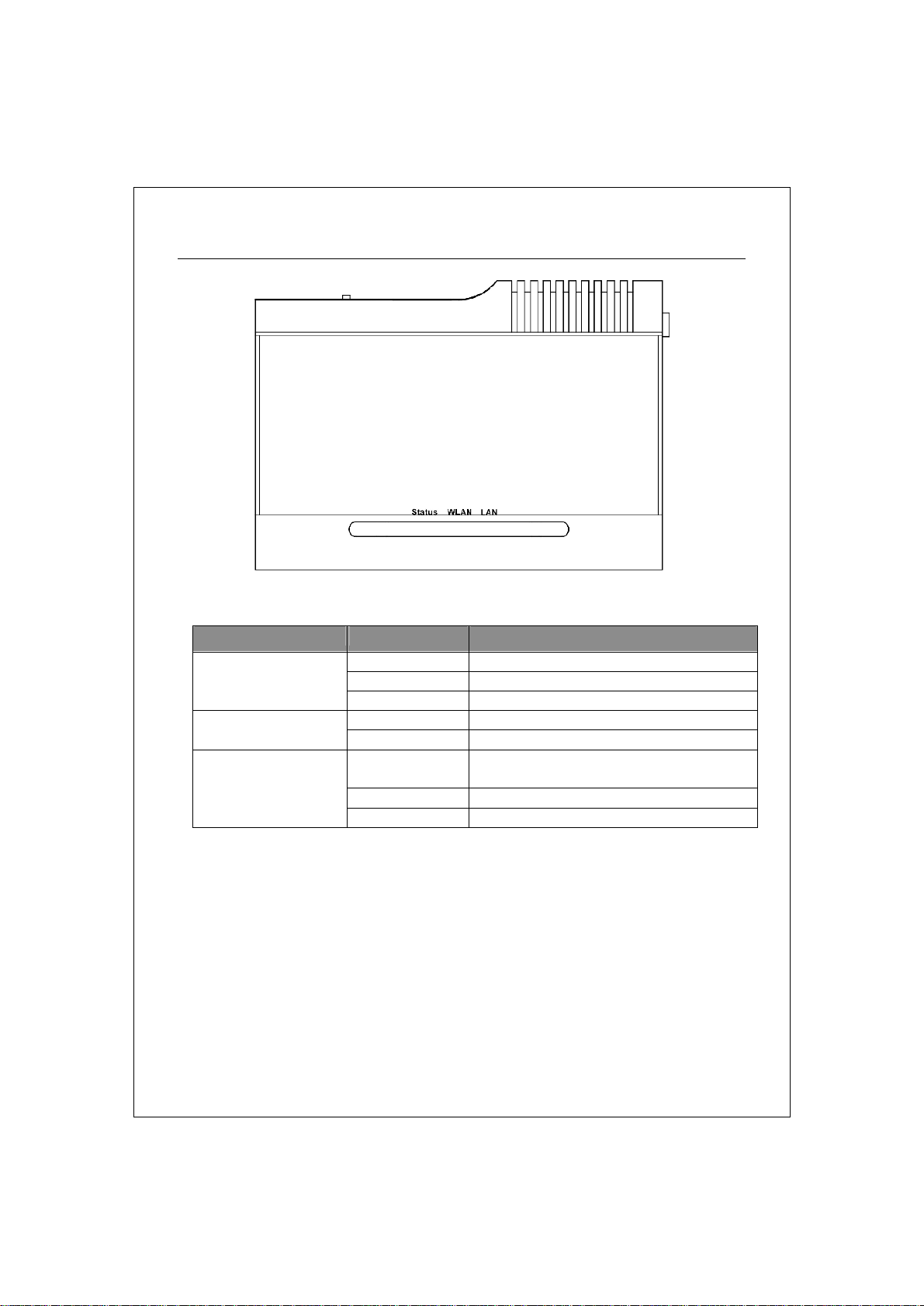
The Front Panel
LED definition
LED Status Definition
Status
LAN
Steady Blue System down or System restarting
Blinking Blue System works normally.
Off System down
Blinking Blue Wireless interface enabled WALN
Off Wireless interface disabled
Blinking Blue Data transmitting/receiving on LAN
port
Steady Blue Valid connection on LAN port
Off Invalid connection on LAN port
3
Page 9
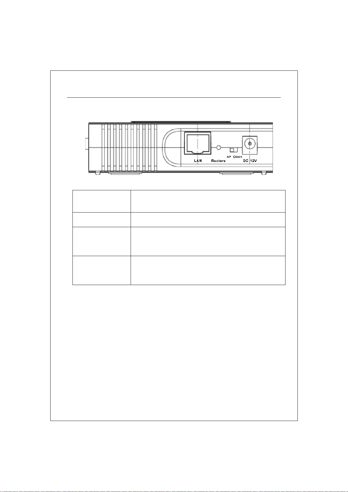
The Rear Panel
Push this switch to either side to function this AP in
DC 12V Plug this connector with the circle end of the
included power adapter. Plug the adapter to an
outlet to power on the AP.
AP/Client switch
AP mode or Client mode.
Restore Press and hold this button for 5 seconds to restore
the default values.
LAN The RJ-45 port for connect this AP to your LAN.
4
Page 10

Connecting This AP to Your Network.
This Chapter provides a step-by-step guide to the installation and
configuration of this wireless access point.
Ø Connect the power adapter with the connector end to the power
connector in the rear panel of the device and the plug end to an
appropriate outlet.
Ø Connect the LAN port with RJ-45 cable to:
1. a broad band router to allow wireless clients to connect to WAN.
2. a switch to allow wireless clients to communicate with wired LAN.
3. a computer directly to use the computer configuring this AP.
Note: You have to configure the network settings of this AP to be
communicable with your router, switch or computer first. To change the default
network settings of the AP, please refer to “LAN Interface setup”.
5
Page 11

Management
Configuring the IP address of your computer
In order to manage with this Wireless AP, you have to configure the IP
addresses of your computer to be compatible with this device.
Note:
1. The default network setting of the device:
IP address: 192.168.1.1
Subnet Mask: 255.255.255.0
Default Gateway: 192.168.1.254
2. In the following TCP/IP configuration guide, the IP address
“192.168.1.2 ” is assumed to be your IP address. Please DO NOT
choose 192.168.1.1 for the IP address (192.168.1.1) has been set as
the default IP for this device.
3. The following TCP/IP configuration guide uses windows XP as the
presumed operation system.
Procedures to configure IP addresses for your computer
1. If you are in Classic Start menu view, click StartàSettingsàControl
PanelàNetwork Connections.
If you are in Start menu view, click StartàControl Panelà Network
Connections.
2. Double click “Local Area Connection”
6
Page 12

3. Choose Internet Protocol (TCP/IP) and click Properties.
4. Choose “Use the following IP address” to specify IP addresses manually.
Fill in the IP addresses in each column. Please click the OK button after your
configuration.
7
Page 13

Starting the WEB-Based Management Interface
The device uses WEB as the management interface. You can use a
browser to access the management interface easily. Please follow up
the steps listed below.
1. Double click the Internet WEB browser icon on your desktop screen
(Netscape Communicator 4.0 and Internet Explorer 3.0 or update
version)
2. Type 192.168.1.1 into the URL WEB address location and press Enter.
3. The Username and Password Required window appears.
- Enter admin in the User Name location (default value).
- Enter admin in the Password location (default value).
- Click “OK” button
8
Page 14

The Graphic User Interaface
After the password authorization, the Setup Wizard shows up as the home
page of the Graphic User interface. You may click on each folder on left
column of each page to get access to each configuration page.
9
Page 15

Status
The Status page shows the following information of the device.
Items Information
Uptime The period that you turn the device on.
Firmware version The current firmware version of the device.
Mode Shows if the device is operating in AP or WDS mode.
Band The band that the wireless AP operating.
SSID The name of this wireless network.
Channel Number The channel that the wireless network using.
Encryption The security encryption type that the wireless network
using.
BSSID The Basic Service Set Identity of this AP(This parameter is
the same as the MAC address of LAN port)
Associated Clients The number of members who is currently connected with
this AP.
Attain IP Protocol The way for this AP to get a IP address.
IP Address The current IP address of this AP.
Subnet Mask The current subnet mask of this AP.
Default Gateway The current default gateway of this AP.
MAC Address The current MAC address of this AP.
10
Page 16

LAN Interface Setup
802.1d Spanning
nt from network loops and preserve the quality of
MAC cloning feature allows the MAC address reported by WAN
This page allows users to configure the LAN network settings.
Configuration
IP address The IP of your AP LAN port (Default 192.168.1.1)
Subnet Mask Subnet Mask of you LAN (Default 255.255.255.0)
Default Gateway The default gateway of this AP.
DHCP
Server
DHCP Client
Range
DNS Server The DNS (domain name server) of this AP.
Domain Name The name that the AP is going to be recognized in LAN.
tree
Clone MAC
Address
Select “Enable” to enable the DHCP server.
Specify the DHCP Client IP address range. You can also click
the “Show Client” button to list those connected DHCP clients.
To preve
bridged network
side network interface card to be set to the MAC address
already registered with the ISP eliminating the need to
register the new MAC address with the ISP. This feature does
not change the actual MAC address on the NIC, but instead
changes the MAC address reported by this device to client
requests. To Change the MAC address, enter it in the text box.
11
Page 17

System Log
This System Log page shows the information of the current activities on the AP.
To enable system log function:
1. Mark the “Enable Log” checkbox.
2. To see all information of the system, select the “system all”
checkbox.
To see wireless information only, select the “wireless” checkbox.
To send the log information to a certain note, select the “Enable
Remote Log” checkbox and fill in the IP address in the “Log Server
IP Address” box.
3. Click the “Apply Changes” button to activate
You could also click the “Refresh” button to refresh the log information or click
the “clear” button to clean the log table.
12
Page 18

Password Setup
This page allows users to configure the username and password for getting
accessed to this WEB based user interface.
To change the username/password, please fill in the username, New password
and click the “Apply Changes” button after confirming the password.
You may also cancel the password authentication by leaving those blanks
empty then clicking the “Apply Changes” button.
13
Page 19

Basic Settings
Disable Wireless
to match 802.11b,
The channel used by the wireless LAN. All devices in the
"Show Active Clients" button, then an "Active
Wireless Client Table" will pop up. You can see the
status of all active wireless stations that are connecting
This page provides setting up the wireless configuration and monitoring the
Wireless Clients that associate with this AP.
Configuration
To Disable interface of Wireless LAN
LAN Interface
Band To select a band for this device
802.11g or both.
AP Mode Type Configure this device as AP, WDS or both.
SSID The name of the wireless network
Country Select the region you live.
Channel Number
same wireless LAN should use the same channel.
Associated Clients Click the
to the access point.
14
Page 20

WDS Setting Click the “Show WDS Setting”
button to configure WDS
Mark this checkbox to enable Universal Repeater Mode
which acts this device as an AP and client
nable the Universal Repeater Mode, you
settings. The WDS settings pops up.
Enable Universal
Repeater Mode
simultaneously.
Root AP SSID While you e
have to specify an SSID for the extended interface.
Click <Apply changes> button at the bottom of the screen to save the above
configurations. You can now configure other advance sections or start using the
AP (with the advance settings in place)
Active Wireless Client Table
This is the window that pops up after clicking the “Show Active Clients”
button.
MAC Address MAC address of this active wireless station.
Tx Packet The number of transmitted packets that are sent out
from this active wireless station.
Rx Packet The number of received packets that are received by
this active wireless station.
TX Rate The transmission rate
Power Saving Shows if the wireless client is in Power Saving mode
Expired Time This is the time in second before dissociation. If the
wireless keeps idle longer than the expired time, this
wireless AP will dissociate it. The wireless client station
has to associate again when it is active.
15
Page 21

Refresh Refresh the "Active Wireless Client Table".
Close Close the "Active Wireless Client Table".
WDS Settings
This is the window that pops up after clicking the “Show WDS Setting”
button.
Wireless Distribution System allows this AP to communicate with other APs
wirelessly. To make it work, you must ensure that these APs are in the same
Channel and add these APs MAC Address and Comment values into the WDS
list. Don’t Forget to Enable the WDS by click the check box of “Enable WDS”
and press “Apply Changes” button to save.
To Delete the AP on the list, Click the check box in the select item and click the
“Delete Selected”. If you want to delete all APs on the list, click “Delete All” to
remove all of them.
16
Page 22

Advanced Settings
Open System
You can set advanced wireless LAN parameters of this AP. The
parameters include Authentication Type, Fragment Threshold,
RTS Threshold, Beacon Interval, Data Rate, Preamble Type,
Broadcast SSID, IAPP and 802.11g Protection.
Configuration
mode
Authentication
Type
Fragment
Threshold
Shared Key
mode
Auto
To specifies the maximum size of packet during the data
transition. The lower values you set, the worst performance
it will be.
Allow communication with no security.
Allow communication with devices with the
same WEP key only.
The wireless client can associate with this AP
by using any one of these two Modes.
17
Page 23

RTS Threshold
ass information
Some 802.11g wireless adapters support 802.11g protection,
which allows the adapters searches for 802.11g singles only.
Select the RF (Radio Frequency) power. The RF output power
If the packet size is smaller the RTS threshold, the AP will
not send this packet by using the RTS/CTS mechanism.
Beacon Interval The period of time how long a beacon is broadcasted.
The "Data Rate" is the data packets limitation this wireless
Data Rate
AP can transmit. The wireless AP will use the highest
possible selected transmission rate to transmit the data
packets.
It defines the length of CRC block in the frames during the
Preamble Type
wireless communication. "Short Preamble" is suitable for
heavy traffic wireless network. "Long Preamble" provides
much communication reliability
If you enable "Broadcast SSID", every wireless station
located within the coverage of this wireless AP can discover
Broadcast SSID
this wireless AP easily. If you are building a public wireless
network, enabling this feature is recommended. Disabling
"Broadcast SSID" can provide better security.
IAPP
To enables multiple AP to communicate and p
regarding the location of associated Stations.
802.11g
Protection
Select the “Disabled” to disable supporting 802.11g
protection or select “enable” to support this function.
RF Output
power
has positive correlation with signal strength.
Some of our wireless adapters supports turbo mode, which
Turbo Mode
provides a better connection quality. Select “Always” to
support turbo mode or select “off” to turn it off . Select
“Auto” turns it on or off automatically.
Click the <Apply Changes> button at the bottom of the screen to save the
above configurations. You can now configure other advance sections or start
using the AP.
18
Page 24

Security
At the page, you can set up the WEP, WPA Encryption to ensure the security of
your Wireless. You will have to do different configurations to each encryption
modes. Click on the Encryption drop list to select an encryption mode or select
“Disabled” to transmitting data without encryption.
WEP Encryption
Configuration
Encryption To enable WEP, WPA, WPA2 and WPA2 Mixed
encryption modes, select the option in the drop
list. If you select none, any data will be
transmitted without Encryption and any station
can access the AP
Key Length Select a key length as 64-bit or 128-bit.
Key Format Select a key format as Hex or ASCII
Default Tx Key Select a default key for transmitting data.
Use 802.1x
Authentication
Mark this check box. Fill in the RADIUS server IP
address, Port Number, and Password to enable
802.1x authentication.
Click <Apply Change> at the bottom of the screen to save the above
configurations. You can now configure other advance sections or start
using the AP.
19
Page 25

WPA Encryption
Configuration
Encryption To enable WEP, WPA, WPA2 and WPA2 Mixed
encryption modes, select the option in the drop
list. If you select none, any data will be
transmitted without Encryption and any station
can access the AP.
WPA Cipher Suite Select the WPA Cipher Suite to be TKIP or AES
WPA Authentication
Mode
Pre-Shared key
Format
Pre-shared Key Enter the Pre-shared Key according to the
Select the WPA mode as “Enterprise
(WPA-Radius)” or “Personal (Pre-Shared Key)”.
Click on the drop list to select an Pre-Shared
Key Format as Passphrase or Hex
pre-shared key format you select.
Click <Apply Change> at the bottom of the screen to save the above
configurations. You can now configure other advance sections or start
using the AP.
20
Page 26

WPA2 Encryption
Configuration
Encryption To enable WEP, WPA, WPA2 and WPA2 Mixed
encryption modes, select the option in the drop
list. If you select none, any data will be
transmitted without Encryption and any station
can access the AP.
WPA2 Cipher Suite Select the WPA2 Cipher Suite to be TKIP or AES
WPA Authentication
Mode
Pre-Shared key
Format
Pre-shared Key Enter the Pre-shared Key according to the
Select the WPA mode as “Enterprise
(WPA-Radius)” or “Personal (Pre-Shared Key)”.
Click on the drop list to select an Pre-Shared
Key Format as Passphrase or Hex
pre-shared key format you select.
Click <Apply Change> at the bottom of the screen to save the above
configurations. You can now configure other advance sections or start
using the AP.
21
Page 27

WPA2 Mixed Encryption
Configuration
Encryption To enable WEP, WPA, WPA2 and WPA2 Mixed
encryption modes, select the option in the drop
list. If you select none, any data will be
transmitted without Encryption and any station
can access the AP.
WPA Cipher Suite Select the WPA Cipher Suite to be TKIP or AES
WPA2 Cipher Suite Select the WPA2 Cipher Suite to be TKIP or AES
WPA Authentication
Mode
Pre-Shared key
Format
Pre-shared Key Enter the Pre-shared Key according to the
Select the WPA mode as “Enterprise
(WPA-Radius)” or “Personal (Pre-Shared Key)”.
Click on the drop list to select an Pre-Shared
Key Format as Passphrase or Hex
pre-shared key format you select.
Click <Apply Change> at the bottom of the screen to save the above
configurations. You can now configure other advance sections or start
using the AP.
22
Page 28

Access Control
To restrict the Number of Access authentication of Stations, Set up the
control list in this page.
Configuration
Wireless Access
Control Mode
MAC Address &
Comment
Current Access
Control list
Click <Apply Change> button to save the above configurations. You can now
configure other advance sections or start using the AP.
Click on the drop list to choose the access control
mode. You may select “Allow listed” to allow those
allowed MAC addresses or select “Deny Listed” to ban
those MAC addresses from accessing to this device.
To set up the Value of MAC Address & Comment; enter
the MAC Address and Comment of station and click
Apply Changes to save.
To Delete the station on the list, Click the check box in
the select item and click the “Delete Selected”. If you
want to delete all stations on the list, click “Delete All”
to remove all of them.
23
Page 29

Statistics
On this page, you can monitor the sent & received packets counters of
wireless, Ethernet LAN, and Ethernet WAN. To see the latest report,
click refresh button.
24
Page 30

Upgrade Firmware
To Upgrade Firmware,
STEPS
1. Click “browse…” button to select the
firmware you want to upgrade.
2. Click Upload to start the upgrade process.
Please don’t close the WEB-browser and
wait for the process to be completed.
25
Page 31

Save and Reload Settings
To save setting to file, click “Save...” button.
To load setting from file,
1. Click “Browse…” on the to select the file
2. Click upload to start the process and wait for it to complete
To reset setting to Default, click the Reset button to start the process.
Log out
Click the “Apply Change” button to log out the system and save your
changes simultaneously.
26
Page 32

Product Specifications
IEEE802.3, 10BASE-T
IEEE802.3u, 100BASE-TX
Standard
Interface
Cable Connections
Network Data Rate
Transmission Mode
LED indications
IEEE802.3x full duplex operation and flow control
IEEE802.11b wireless LAN infrastructure
IEEE802.11g wireless LAN infrastructure
1 * LAN port
Antenna: 802.11b/g wireless reverse SMA detachable
RJ-45 (10BASE-T): Category 3,4,5 UTP
RJ-45 (100BASE-TX): Category 5 UTP
802.11b: 1, 2, 5.5 and 11Mbps
802.11g: 6, 9, 12, 18, 24, 36, 48, and 54Mbps
Auto-Negotiation (Full-duplex, Half-duplex)
1*Power, 1*WLAN, 1*LAN
Security
Receiver Sensitivity
Memory
Transmit Power
Range Coverage
Emission
Environmental
64/128-bit WEP, WPA(TKIP with IEEE 802.1x), WPA2, AES
54Mbps OFDM, 10%PER, -68dBm
11Mbps CCK, 10%PER, -86dBm
1Mbps BPSK, 10%PER, -93dBm
Flash: 2MB, SDRAM : 8MB
11b: 22.64dBm
11g: 24.23dBm
Indoor 30m at 54Mbps,Outdoor 61m at 54Mbps.
FCC CLASS B, CE
Operating Temperature: 0° ~ 40°C (32° ~ 104°F)
Storage Temperature: -10° ~ 70°C (-14° ~ 140°F)
Humidity: 10 ~ 95% RH non-condensing
27
Page 33

Antenna
Power Supply
Channel
Emission
External Power Adapter, 12VDC/ 1A
Antenna Gain: 2 DBI
Antenna Type: DIPOLE
Antenna Connector Type: REVERSE SMA
USA 11, Europe 13, Japan 14, Taiwan 11,
FCC Part 15.247 for US, (2.412~2.462MHz)
ETS 300 328 for Europe, (2.400~2483.5 MHz)
DGT LP0002 for Taiwan (2.412~2.462MHz)
28
 Loading...