

Page 1

NetPoint Pro 6X2.4
Outdoor Wi-Fi Base Station
Installation Guide
Rev. 7
August 2008
Note: To better reflect the value of Netronics products we are changing the name of our
product family from NetPoint to NetPoint Pro, consequently the name for the existing product
with 6 antennas will be NetPoint Pro 6X2.4.
The new product name emphasizes the difference in ar chitecture (Multiple Radio system) and
the value to customer, superiority in performance (covera ge, capacity, indoor penetration and
immunity to interference) of Netronics WiFi base station over any other standard outdoor WiFi
access point products available in the market.
Copyright Notice
Page 2

©2006, 2007, 2008 Netronics, Inc. All rights reserved. Netronics is a registered trademark of
Netronics in the Canada and certain other jurisdictions. Specifications are subject to change
without notice.
FCC Notice to Users and Operators
This equipment has been tested and found to comply with the limits for a Class B digital device,
pursuant to Part 15 of the FCC Rules. These limits are designed to provide reasonable
protection against harmful interference when the equipment is operated in a commercial
environment. This equipment generates, uses, and can radiate radio frequency energy and, if
not installed and used in accordance with the instruction manual, may cause harmful
interference to radio communications. Operation of this equipment in a residential area is likely
to cause harmful interference, in which case the user will be required to correct the interference
at his own expense. If this equipment does cause interference to radio or television reception,
which can be determined by turning the equipment off and on, the user is encouraged to
correct the interference by using one of the following measures:
• Reorient or relocate the receiving antenna.
• Increase separation between the equipment and receiver.
• Connect the equipment to an outlet on a circuit different from that to which the receiver is
connected.
• Consult the dealer or an experienced radio/TV technician.
Page 3

Installation Guide 3
Page 4

4 Netronics Networks
Contents
Chapter 1 About This Guide ....................................................................... 6
Preface .......................................................................................................... 6
Conventions ................................................................................................... 6
Contacting Technical Support ........................................................................... 7
Chapter 2 Introduction .............................................................................. 8
Chapter 3 Installing the Netronics NPP 6X2.4 Metro Base Station ......... 10
Important Safety Instructions ......................................................................... 11
Preparing for Installation ................................................................................ 12
Installation Hardware and Tools .............................................................. 13
Choosing a Location ............................................................................... 13
Preparing the Site .................................................................................. 13
Power Source Options ............................................................................ 14
Safety Precautions ................................................................................. 14
Mounting Strategies ....................................................................................... 14
Using Hose Clamps ........................................................................................ 15
Mounting on a Pole, or Streetlight ................................................................... 16
Metal or Wood Pole Mounting ................................................................. 16
Wood Brace Mounting ............................................................................ 20
Streetlight Mounting ............................................................................... 22
Grounding the Netronics NPP 6X2.4 ................................................................. 25
Grounding the Data Protection Device ...................................................... 27
Connecting Antennas ..................................................................................... 27
Connecting Power .......................................................................................... 28
Connecting to AC Power (Category C) ...................................................... 29
Connecting to Streetlight Power (Category C) ........................................... 32
Connecting to DC Power ......................................................................... 33
Connecting a Data Port .................................................................................. 35
Connecting Peripherals ................................................................................... 39
PoE Power Sourcing Power Output .......................................................... 39
Using a Backhaul Unit ............................................................................. 40
Safety Information for the Netronics NPP 6X2.4 ............................................... 41
Service Instructions........................................................................................ 42
Chapter 4 Power Consumption ................................................................ 44
Chapter 5 Product Specification .............................................................. 45
Chapter 6 Installation Accessories .......................................................... 49
Power Cable .......................................................................................... 50
Ethernet Cables ..................................................................................... 50
Lightning Protection ............................................................................... 50
Power Over Ethernet .............................................................................. 50
Client Connectivity ................................................................................. 50
Chapter 7 AC Wiring Diagrams ................................................................ 53
AC Wiring Photoelectric Power Tap .......................................................... 53
Page 5

Installation Guide 5
AC Wiring Power Cable 120VAC, 15A Plug ................................................ 55
Chapter 8 Wind Loading Considerations ................................................. 57
Chapter 9 Backhaul Unit Installation Instructions .................................. 59
Chapter 10 Acronyms ................................................................................ 61
Chapter 11 Appendix A: NPP 6X2.4 Product list ........................................ 64
Page 6

6 Netronics Networks
Chapter 1
About This Guide
Preface
This guide details the Netronics NPP 6X2.4 installation procedures. The intended audience of
this document is trained technical professionals.
Conventions
The exclamation point within a triangle is intended to alert the user to the presence of
important operating and maintenance (servicing) instructions in the literature
accompanying the product.
The lightning flash with an arrowhead symbol within a triangle is intended to alert the
user to the presence of un-insulated dangerous voltage within the product’s enclosure
that may be of sufficient magnitude to constitute a risk of electric shock to persons.
The notebook is intended to alert the user of a note containing further information.
Page 7

Installation Guide 7
Contacting Technical Support
For technical support, contact Netronics using these methods:
Email:
Web:
www.Netronics-networks.com
Page 8

8 Netronics Networks
Chapter 2
Introduction
The NPP 6X2.4 is a new category of Wi-Fi Base Station designed from the ground up for metroWi-Fi deployments. It is based on six antennas and radios and custom-built ASICs, utilizes
Netronics's powerful multi-antenna signal processing technologies, and provides significant
performance gains to off-the-shelf 802.11 standards-based Wi-Fi clients.
The NPP 6X2.4 may be mounted on streetlights or rooftops and may be easily interfaced with
either wired internet connections, wireless mesh or backhaul equipment. Multiple power options
are provided for maximum flexibility.
Complete management of the NPP 6X2.4 is provided through SNMP, a graphical user interface,
and SYSLOG services.
The NPP 6X2.4 Wi-Fi Base Station uses six omni-directio nal antennas and beam-forming
technology in order to provide significant performance gains to off-the-shelf 802.11 standardsbased Wi-Fi clients.
Page 9

Introduction
Installation Guide 9
Page 10

10 Netronics Networks
Chapter 3
Installing the Netronics NPP 6X2.4 Metro Base
Station
This guide explains how to safely install the Netronics NPP 6X2.4 Metro Base Station. The
following topics are covered in this chapter:
• Important Safety Instructions on page 11
• Preparing for Installation on page 12
• Mounting Strategies on page 14
• Using Hose Clamps on page 15
• Mounting on a Pole, or Streetlight on page 16
• Grounding the Netronics NPP 6X2.4 on page 25
• Connecting Antennas on page 27
• Connecting Power on page 28
• Connecting a data port on page
35
• Connecting Peripherals on page 39
• Safety Information for the Netronics NPP 6X2.4 on page 41
• Service Instructions on page 42
Page 11
Installing the Netronics NPP 6X2.4 Metro Base Station
Installation Guide 11
Important Safety Instructions
WARNING: It is illegal to modify the construction of this product. Modifying the
operating frequency or enhancing the transmit output power through the use of
external amplifiers or other equipment is specifically disallowed by the
"Telecommunications Act."
WARNING: This device is for outdoor or indoor use with conditions that no harmful
interference to authorized radio stations results from the operation of this device. This
device shall not influence aircraft security and/or interfere with legal communications
as defined in the "Telecommunications Act." If this device is found to cause
interference, the operator of this equipment shall cease operating this device
immediately until no interference is achieved.
Note: This device must be installed by a trained professional, value added reseller or
systems integrator who is familiar with RF planning issues and the regulatory limits in
the United States of America.
Caution:Readandsavetheseinstructions.Heedallwarnings.Followallinstructions.
Do not defeat the safety purpose of the grounding.
Caution: Only use attachments/accessories specified by the manufacturer.
Caution: Refer all servicing to qualified service personnel. Servicing is required when
the apparatus has been damaged in any way. For example, if the power-supply cord
or plug is damaged, liquid has been spilled on the apparatus, objects have fallen into
the apparatus, the apparatus has been exposed to rain or moisture, it does not
operate normally, or has been dropped.
Warning: Risk of personal injury or death when installing this device! There is a risk
of personal injury or death if the NPP 6X2.4 antennas come near electric power lines.
Carefully read and follow all instructions in this manual. By nature of the installation,
you may be exposed to hazardous environments and high voltage. Use caution when
installing the outdoor system.
Warning: This apparatus must be connected to earth ground
Warning: Do not open the unit. There is a risk of electric shock inside.
Caution: You are cautioned that any change or modification not expressly approved
in this manual could void your authority to operate this equipment.
Caution: There are no user-serviceable parts inside. All service must be performed
by qualified personnel.
Page 12

12 Netronics Networks
Caution: The RJ45 connectors of your Netronics NPP 6X2.4 may source DC power on
pins 4,5 and 7,8. The IEE 802.3 standards allow for pins 4,5 and 7,8 to be used for
Power Over Ethernet. Some products may be incompatible with the Netronics Power
Over Ethernet capability.
CautionOnlyULlistedpartsandcomponentswillbeusedforinstallation.UseULlisteddevices
havinganenvironmentalratingequaltoorbetterthantheenclosureratingtocloseallunfilled
openings.
CautionTomaintainOvervoltage(Installation)CategoryII,installasuitablesurgesuppressordevice
inthebranchcircuittolimitexpectedtransientstoOvervoltageCategoryIIvalues.Thelimitsare
basedonIEC60664andarealsolocatedinTable2HofUL60950(formains110V,thetransientrating
is1500V).
Caution The NPP 6X2.4 must be installed only with the equipped antennas.
CautionAminimumdistanceof40cmfromtheNPP6X2.4'santennashouldbekeptwhenthesystem
isoperated.
CautionReadandsavetheseinstructions.Heedallwarnings.Followall
instructions
Preparing for Installation
The Netronics NPP 6X2.4 must be installed by a trained professional, or systems integrator who
is familiar with RF planning issues and regulatory limits as defined by the governing body of the
country in which the unit will be installed.
The following lists the equipment required for installation and explains how to prepare the
installation site.
WARNING: Do not modify the construction of this product. Modifying the operating
frequency or enhancing the transmit output power through the use of external
amplifiers or other equipment is illegal.
WARNING This device is for use outdoors or indoors on the condition that operation
of this device causes no harmful interference to authorized radio stations. This device
shall not influence aircraft security and/or interfere with legal communications. If this
device is found to cause interference, the operator of this equipment shall cease
operating this device immediately.
Page 13

Installation Guide 13
Installation Hardware and Tools
Netronics provides the following accessories to install the Netronics NPP 6X2.4:
• One pole bracket
• Two 3-6-inch diameter worm drive hose clamps
• Seven 8mm stainless steel hex head machine bolts
• Allen wrench - 4mm and 5mm
• Six Antennas
You must supply the following tools:
• 1/4-inch flat blade screwdriver
• Wood brace mounting only: four 5/8-inch diameter, 3-inch long lag bolts
Choosing a Location
The Netronics NPP 6X2.4 is a radio device and susceptible to interference that can reduce
throughput and range. To ensure the best performance follow these guidelines:
• Direct line-of-sight operation is preferred.
• It is recommend not to install the NPP 6X2.4 near devices operating in the 2.4 GHz
frequency range.
• The NPP 6X2.4 should be installed at the highest point of a metal pole such that there will be
no interference caused by RF reflections. If this is not possible, the NPP 6X2.4 should be
installed at least 3 meters from the metal pole.
• It is always best to have the maximum distance possible from an RF radiating source.
Preparing the Site
When installing the Netronics NPP 6X2.4, you must follow the appropriate electrical and building
codes to ensure safe and durable wiring. Follow the National Electrical Code (NEC)
requirements, unless local codes in your area take precedence over the NEC code.
For installations that have 10/100 Base-T Category 5 network cables attached to the Netronics
NPP 6X2.4, there is a distance limit of 100m maximum between devices for 10/100BaseT
operation.
An appropriate ground cable should be available. Grounding through electrical wiring or CAT-5
cable is not sufficient.
Please refer to standards for building entrance protection.
Page 14

14 Netronics Networks
Power Source Options
The Netronics NPP 6X2.4 supports the following options for connecting to a power source
(Power options availability depend on specific device model):
• AC power source (3-wire service) -- 3W(P+N+PE) or 3W(2P+PE); 110-220 VAC, 50/60 Hz.
See Installation Accessories on page 49 for details.
• NEMA plug, for streetlight photoelectric control power tap (2-wire service) --2W(2P) or
2W(P+N); 100-240 VAC 50/60 Hz. See Installation Accessories on page 49 for details.
• DC power source (2-wire service); 48VDC. See Installation Accessories on page 49 for
details.
• The NPP 6X2.4 can be powered by a Netronics Injector connected to Ethernet port B (ETH
B). See Installation Accessories on page 49 for details.
Warning: Use only a rated power source to connect the AC powered outdoor system.
Do not connect to a power source of different voltage.
Caution: You must always install an external grounding wire. You must also ground
the outdoor data protection device to a bonded pipe or ground rod. Perform a simple
continuity check between the NPP 6X2.4 and the ground termination point to confirm.
Make sure that grounding is complete before you connect power to the Netronics NPP
6X2.4.
Safety Precautions
Installing the Netronics NPP 6X2.4 can be very hazardous. Take precautions to avoid the
following:
• Exposure to high voltage lines
• Contact with AC wiring
• Injuries from dropped tools and equipment
• Falls when working at heights or with ladders
Mounting Strategies
Consider the available mounting structures and antenna clearance when choosing a mounting
location. The Netronics NPP 6X2.4 should always be mounted with the top of the unit parallel to
the ground, and with the antennas pointing upward and clear of obstruction.
It is recommended to attach ground and data cables to the NPP 6X 2.4 prior to mounting.
Before mounting the NPP 6X2.4, read the wiring instructions in
Grounding the Netronics NPP
6X2.4
on page 25 and Connecting a Data Port on page 35.
Page 15
Installation Guide 15
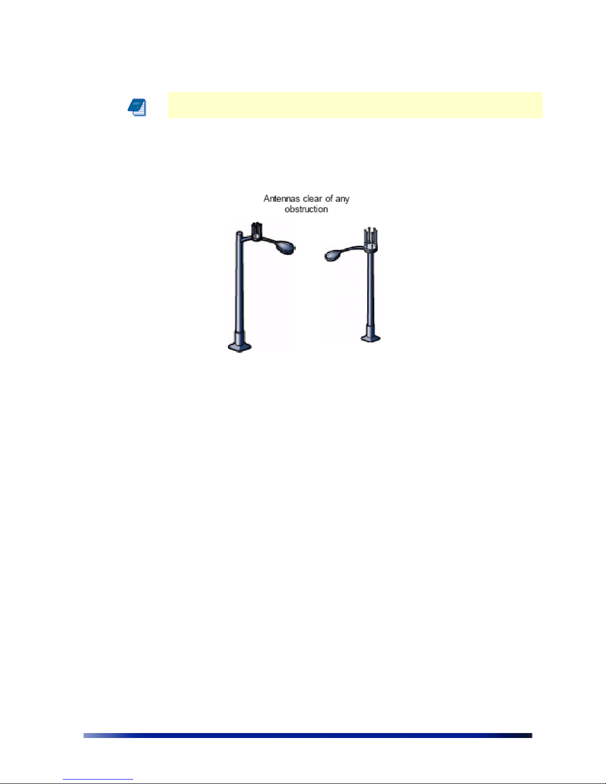
Note: The NPP 6X2.4 should be mounted with at least 4 ft of clearance around the
antennas to eliminate potential interference from the mounting structure.
Figure 3.1 demonstrates acceptable options for mounting on a streetlight. In both cases the
NPP 6X2.4 is mounted to ensure clearance for the antennas above the height of the streetlight.
Figure 3.1 Example Mounting Locations on a Streetlight
Using Hose Clamps
Hose clamps are used by the mounting assembly to secure the NPP 6X2.4 to the mounting
structure.
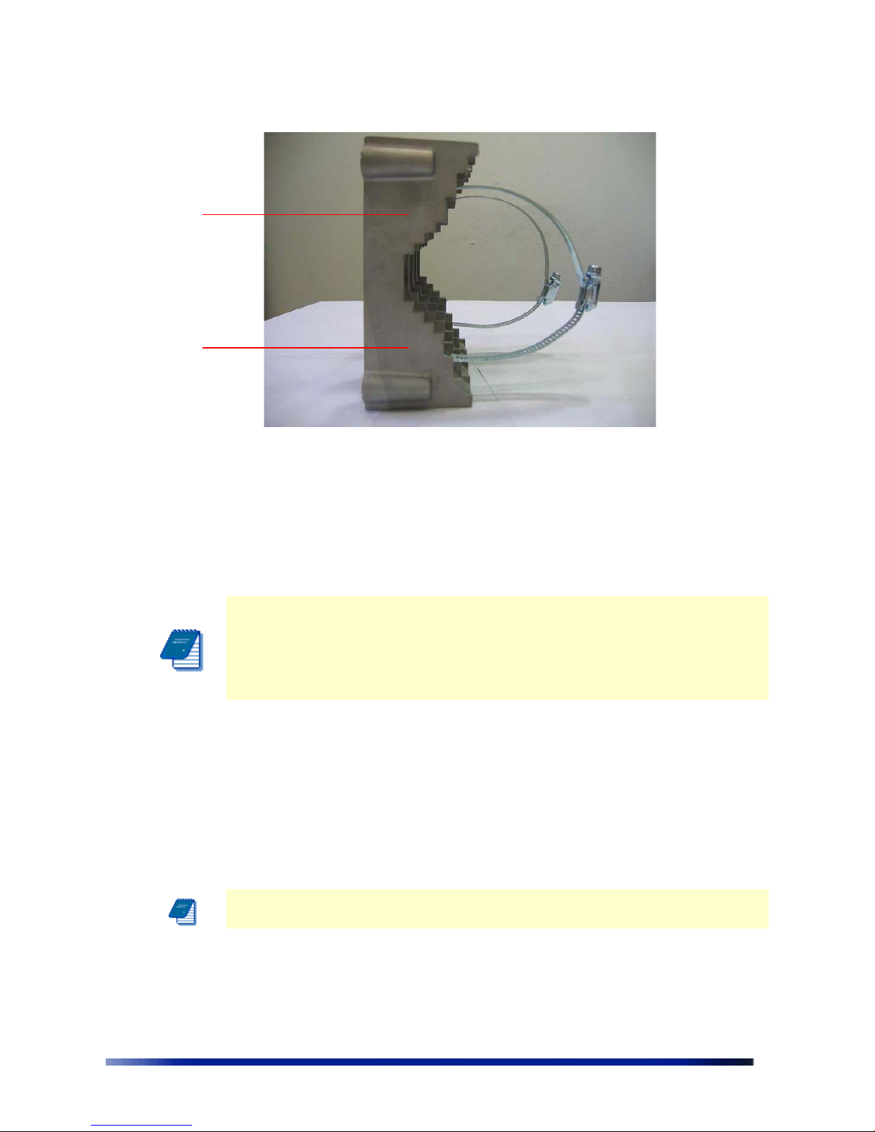
Figure 3.2 demonstrates how to correctly use the hose clamps. The bands must be
threaded through slots in the pole bracket, and then attached to either a vertical or a horizontal
pole and tightened.
There are three slots inside the pole bracket that can used to thread each hose clamp. Choose
the slot that is appropriate for the size of the pole.
Page 16
16 Netronics Networks
Figure 3.2 Using Hose Clamps
Mounting on a Pole, or Streetlight
The following explains how to mount the Netronics NPP 6X2.4 on a pole, tower, or streetlight. It
is recommended to mount the NPP 6X2.4 on aluminum or galvanized steel structures.
Note The Netronics NPP 6X2.4 must be mounted with the top of the unit parallel with
the ground and with the antennas pointing upward.
Note Before mounting the NPP 6X2.4, read the wiring instructions in Grounding the
Netronics NPP 6X2.4 on page 25 and Connecting a Data Port on page 35.
Note Mounting to wood, concrete, or painted poles requires primary grounding for
the unit. Check the national electrical codes in your area for specific rules.
Metal or Wood Pole Mounting
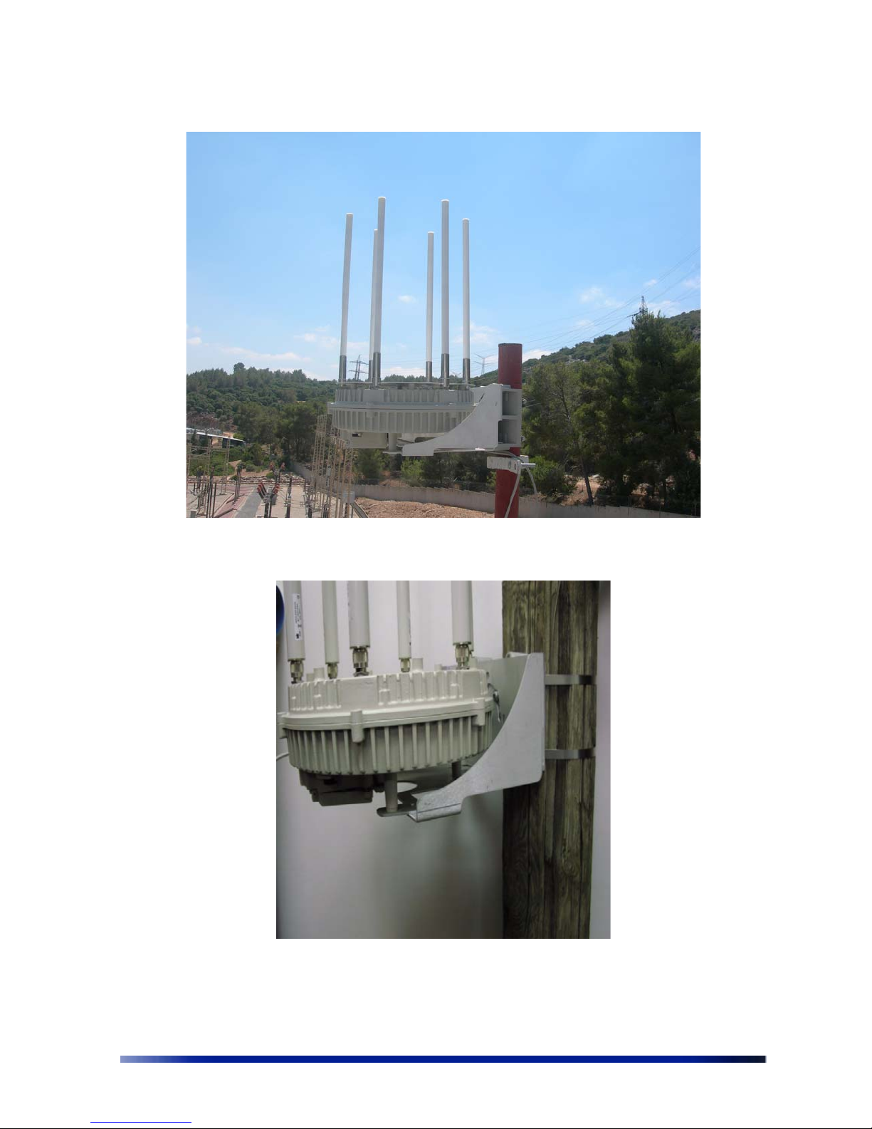
Figure 3.3 shows the correct way to mount the Netronics NPP 6X2.4 on an outdoor metal pole.
Figure 3.4 shows the correct way to mount the Netronics NPP 6X2.4 on an outdoor wooden
pole. There is much similarity between the two installations. Metal pole installation requires that
the antennas are higher than the top of the pole. This is not a requirement for wooden poles.
Note Antennas must be higher than the top of the metal pole and clear of any
obstructions
Bands threaded
through inner
slots
Page 17
Installation Guide 17
Figure 3.3 Mounting on a Metal Pole
Figure 3.4 Mounting on a Wooden Pole
Page 18

18 Netronics Networks
To mount the Netronics NPP 6X2.4 on a metal or wood pole:
1. Choose a mounting location. You can attach the NPP 6X2.4 to any pole or pipe with
diameter of 3-10 inches. Wooden poles of larger diameter require different types of
clamps.
2. Slip the bands of the hose clamps through the inner slots of the pole bracket. Choose the
slot that is appropriate for the diameter of the mast.
3. Use the hose clamps to fasten the pole bracket to the pole.
Note The hose clamps supplied support a mast diameter of 3-6 inches. You can
supply your own hose clamps if you need a different size.
Note Installations on large wooden poles require band clamps such as those supplied
by Panduit, www.panduit.com. Such a product is listed as "Metal, Locking Tie Extra
Heavy Duty 304 Stainless Steel". The tie and the installation tool are shown below
Figure 3.5 Wood Pole Mounting Tool and Clamp
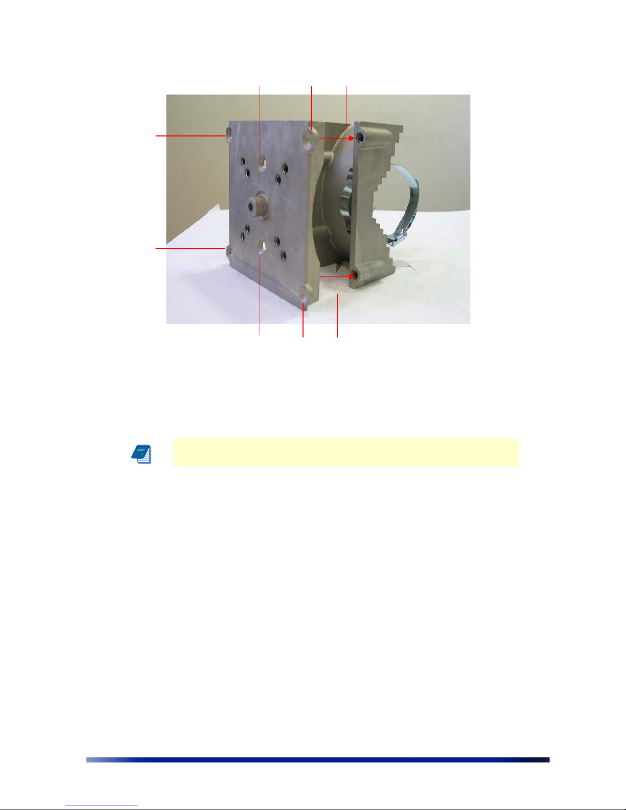
4. Attach the back plate to the hose bracket as labeled #1 in The Figure
5. Insert the six flathead bolts into the holes in the back plate labeled #2 in The Figure and
tighten.
Page 19
Installation Guide 19
Figure 3.6 Attaching the Back Plate to the Pole Bracket
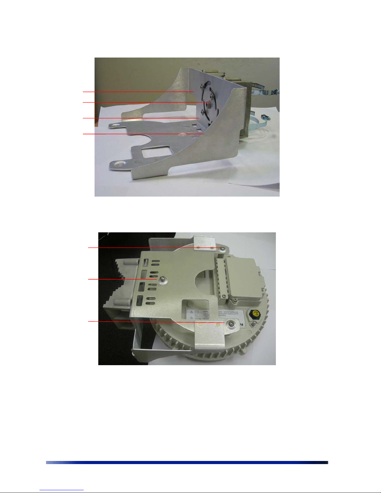
6. Attach the tray to the back plate as shown in
Figure 3.7.
Note The tray must be parallel to the ground. The tray can be rotated to
obtain the correct position.
7. Insert the four 8mm stainless steel hex head bolts into the tray as shown below and
tighten. Use a 5mm Allen wrench to tighten the bolts.
2
2
2
2 2
2
1
1
Page 20
20 Netronics Networks
Figure 3.7 Attaching the Tray to the Back Plate
8. Slide the NPP 6X2.4 onto the tray. Insert three 8mm stainless steel hex head bolts from
underneath the tray into the NPP 6X2.4. Use a 5mm Allen wrench to tighten the bolts.
Figure 3.8 Attaching the NPP 6X2.4 to the Tray
To continue installing the NPP 6X2.4, see
Grounding the Netronics NPP 6X2.4 on page 25
Wood Brace Mounting
You can mount the tray directly onto a wood brace without using pole hose clamps.
Insert
bolts
Insert
bolts
Page 21
Installation Guide 21
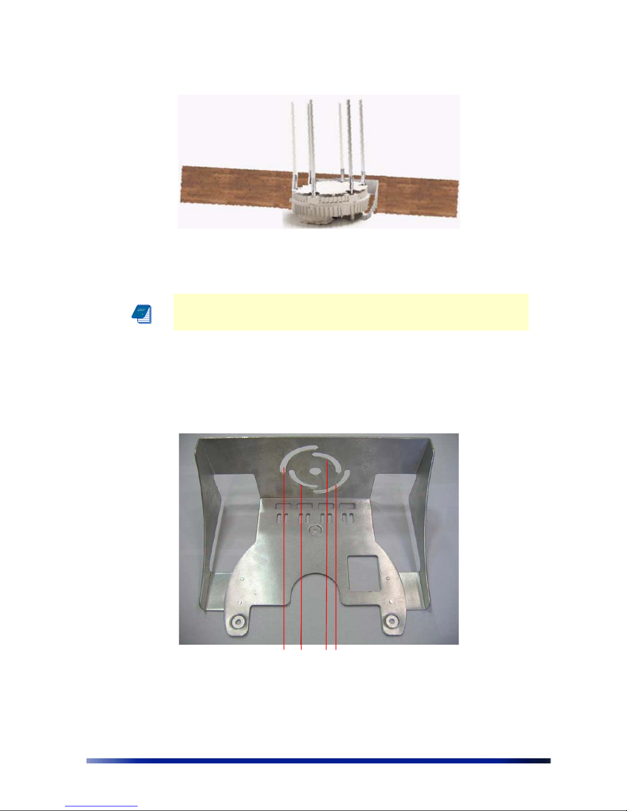
Figure 3.9 Wood Brace Mounting Option
You can attach the NPP 6X2.4 to any wood brace.
Note Before attaching the NPP 6X2.4 make sure that the wood can support
the NPP 6X2.4 weight plus wind loading. Please see Chapter 9 for wind loading
considerations.
To mount the Netronics NPP 6X2.4 on a wood brace:
1. Select a mounting location.
2. Attach the tray directly to the wood brace using four 5/8 inch diameter, 3 inch long lag
bolts as shown in
0. Use an appropriate Allen wrench to tighten the bolts. Make sure
that the wood brace is level.
Figure 3.10 Tray Mount for Wood Brace
Page 22
22 Netronics Networks
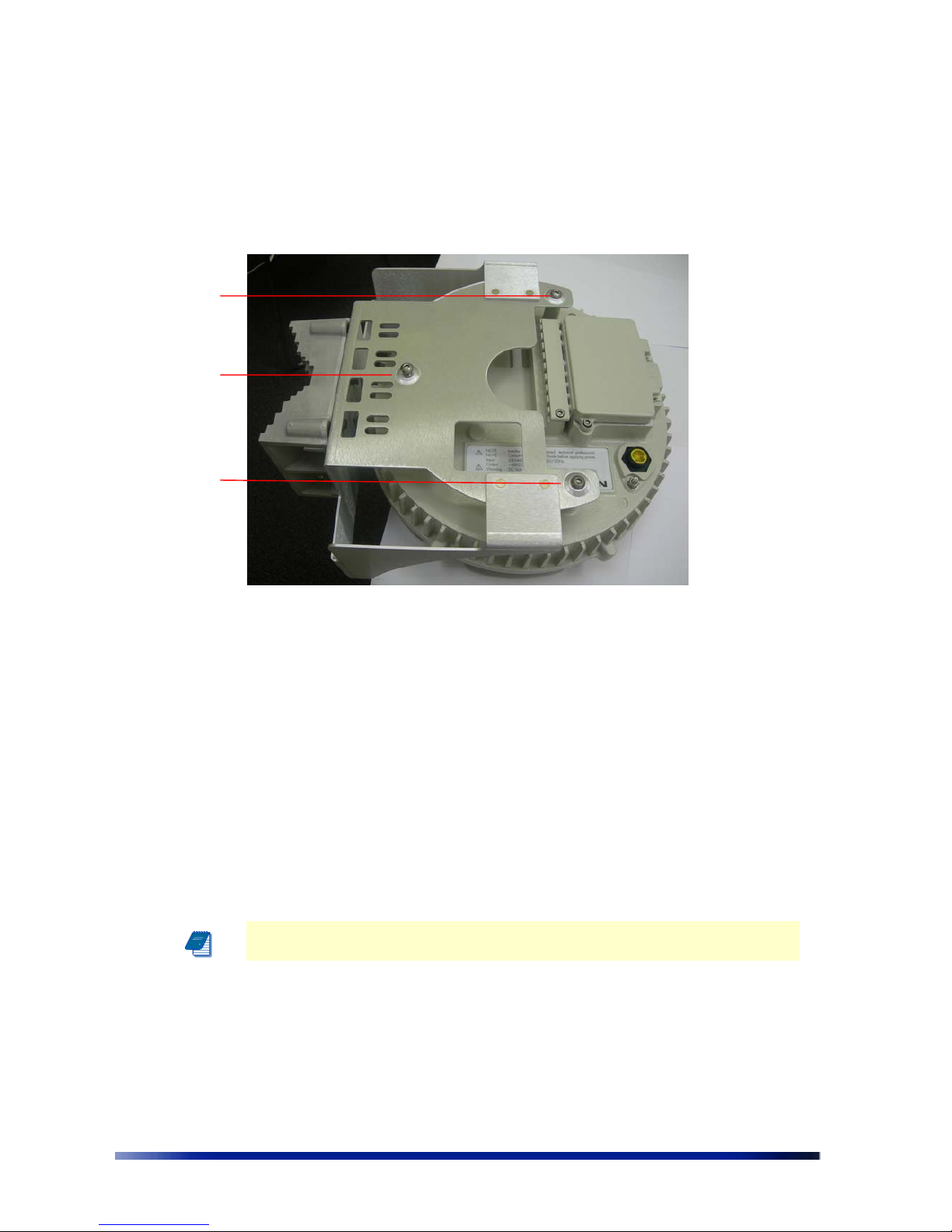
3. Slide the NPP 6X2.4 onto the tray. Insert three 8mm stainless steel hex head machine
bolts from underneath the tray into the NPP 6X2.4. Use a 5mm Allen wrench to tighten
the bolts.
Figure 3.11 Attaching the NPP 6X2.4 to the Tray
To continue installing the NPP 6X2.4, see Grounding the Netronics NPP 6X2.4 on page 25
.
Streetlight Mounting
You can mount the Netronics NPP 6X2.4 on the horizontal or angled arm of a streetlight.
To mount the Netronics NPP 6X2.4 on a streetlight:
1. Choose a mounting location. You can attach the NPP 6X2.4 to any streetlight arm with
diameter of 3 to 10 inches.
2. Slip the bands of the hose clamps through the inner slots of the pole bracket. Choose
the slot that is appropriate for the diameter of the mast.
3. Use the hose clamps to fasten the pole bracket to the pole.
Note The hose clamps supplied supports a mast diameter of 3-6 inches. You
can supply your own hose clamps is you need a different size.
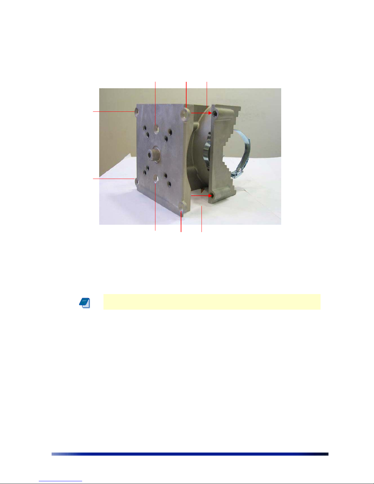
4. Attach the back plate to the pole bracket as labeled #1 in Figure 3.12
5. Insert the six bolts into the holes in the back plate labeled #2 in
Figure 3.12 and
tighten.
Insert
bolts
Page 23
Installation Guide 23
Figure 3.12 Attaching the Back Plate to the Pole Bracket
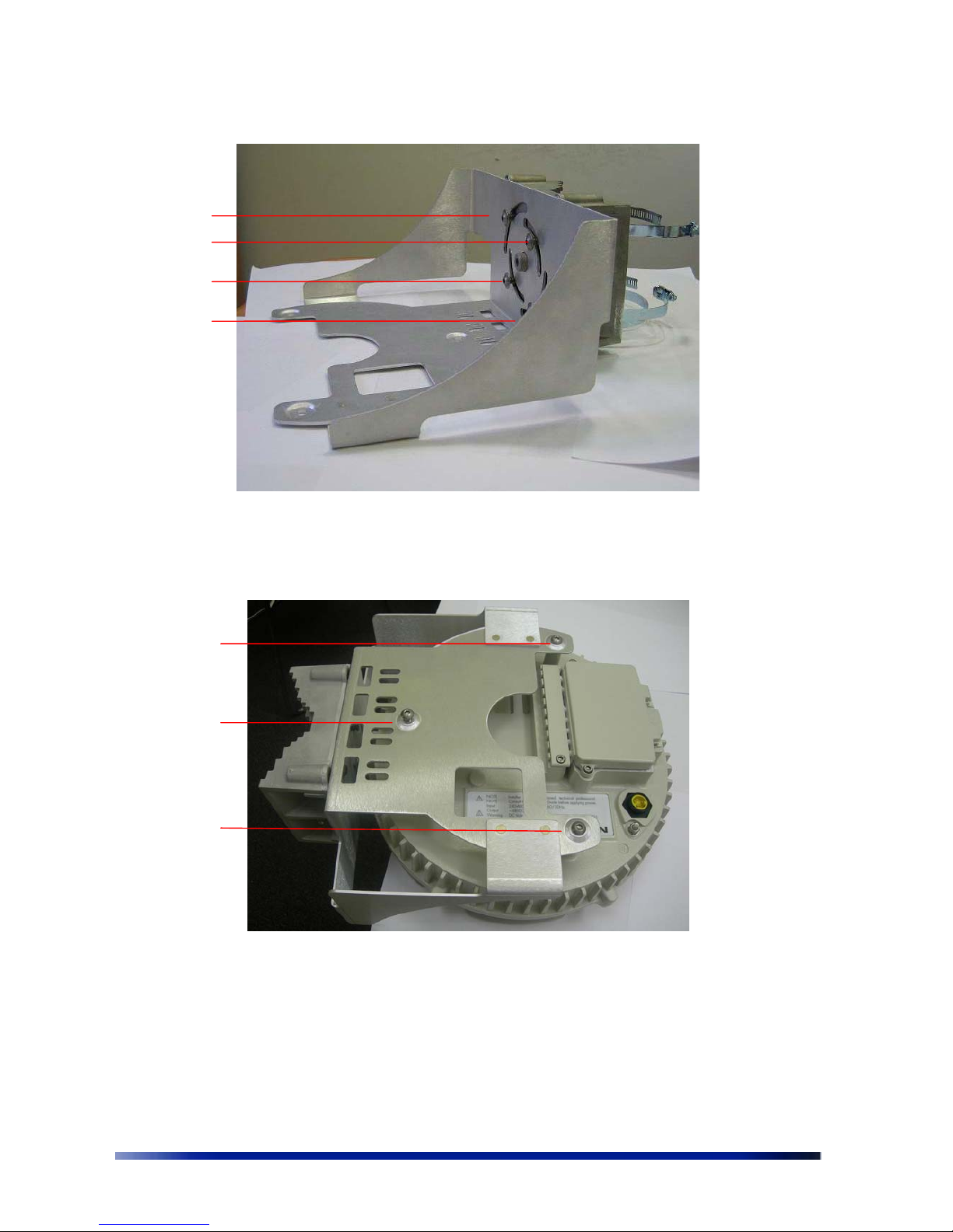
6. Attach the tray to the back plate as shown in
Figure 3.13.
Note The tray must be parallel to the ground. The tray can be rotated to obtain
the correct position.
7. Insert four 8mm stainless steel hex head machine bolts into the tray. Tighten the bolts
using a 5mm Allen wrench.
2
2
2
2 2
2
1
1
Page 24
24 Netronics Networks
Figure 3.13 Attaching the Tray to the Back Plate
8. Slide the NPP 6X2.4 onto the tray. Insert 3 8mm stainless steel hex head machine bolts
from underneath the tray into the NPP 6X2.4 and tighten the bolts. Tighten the bolts
using a 5mm Allen wrench.
Figure 3.14 Attaching the NPP 6X2.4 to the Tray
To continue installing the NPP 6X2.4, see
Grounding the Netronics NPP 6X2.4 on page
25.
Insert
bolts
Insert
bolts
Page 25
Installation Guide 25
Grounding the Netronics NPP 6X2.4
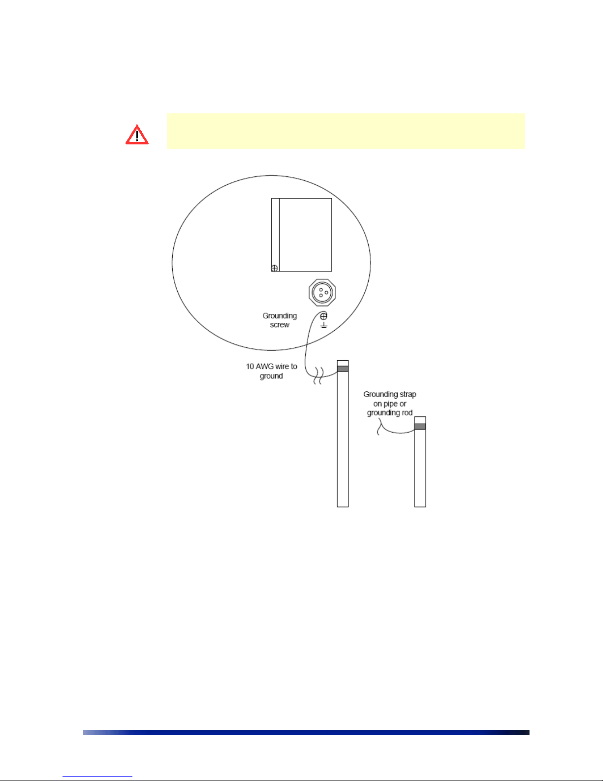
Caution: You must always install an external grounding wire. You must also
ground the outdoor data protection device to a ground rod or a bonded pipe. Make
sure you have completed grounding before you connect power to the NPP 6X2.4.
The method for grounding the Netronics NPP 6X2.4 is shown in the figure below.
Figure 3.15 Grounding Method
To ground the Netronics NPP 6X2.4:
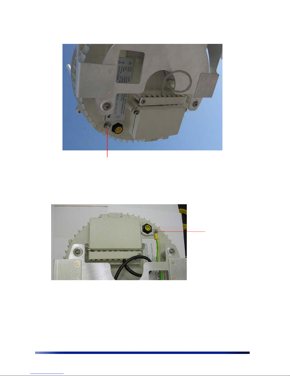
1. Remove the nut and star washers from the grounding screw.
Page 26
26 Netronics Networks
Figure 3.16 Grounding Screw
2. Attach one star washer to the grounding screw.
3. Attach #10 AWG bare copper wire with an M6 terminal ring to the grounding screw.
4. Attach the second star washer and tighten the nut.
5. Attach the other end of the grounding wire to a grounding strap that is attached to a
grounded surface or other earth ground (for example, a grounding rod).
Grounding Screw
Attach wire to
grounding
screw
Page 27
Installation Guide 27
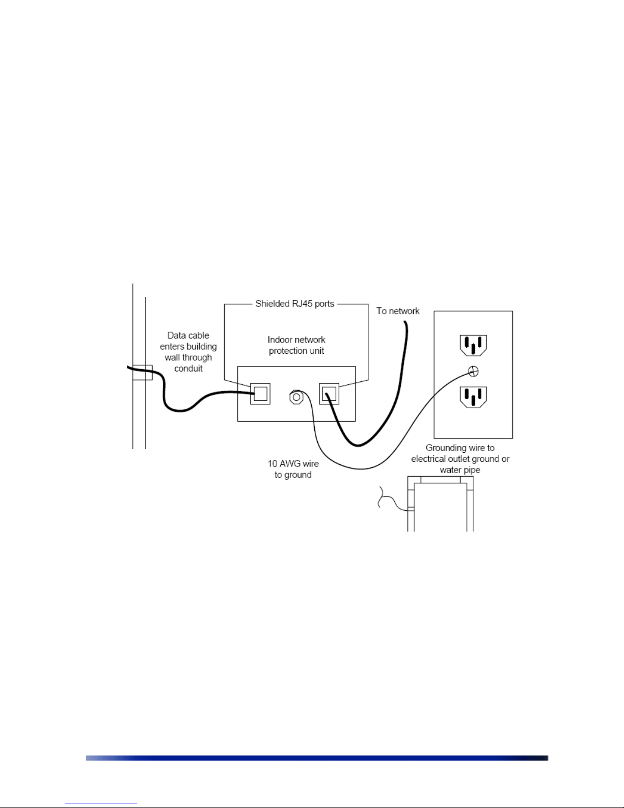
Grounding the Data Protection Device
The grounding method for an indoor data protection device is shown in Figure 3.17.
To ground an indoor data protection device:
1. Position the protection device as close to the entrance of the building entrance as
possible.
2. Attach a length of #10 AWG bare copper wire to the ground post on the data protection
device.
3. Attach the other end of the grounding wire to the ground connection of an electrical
outlet or a grounded water pipe.
Figure 3.17 Grounding the Indoor Network Protection Unit
Connecting Antennas
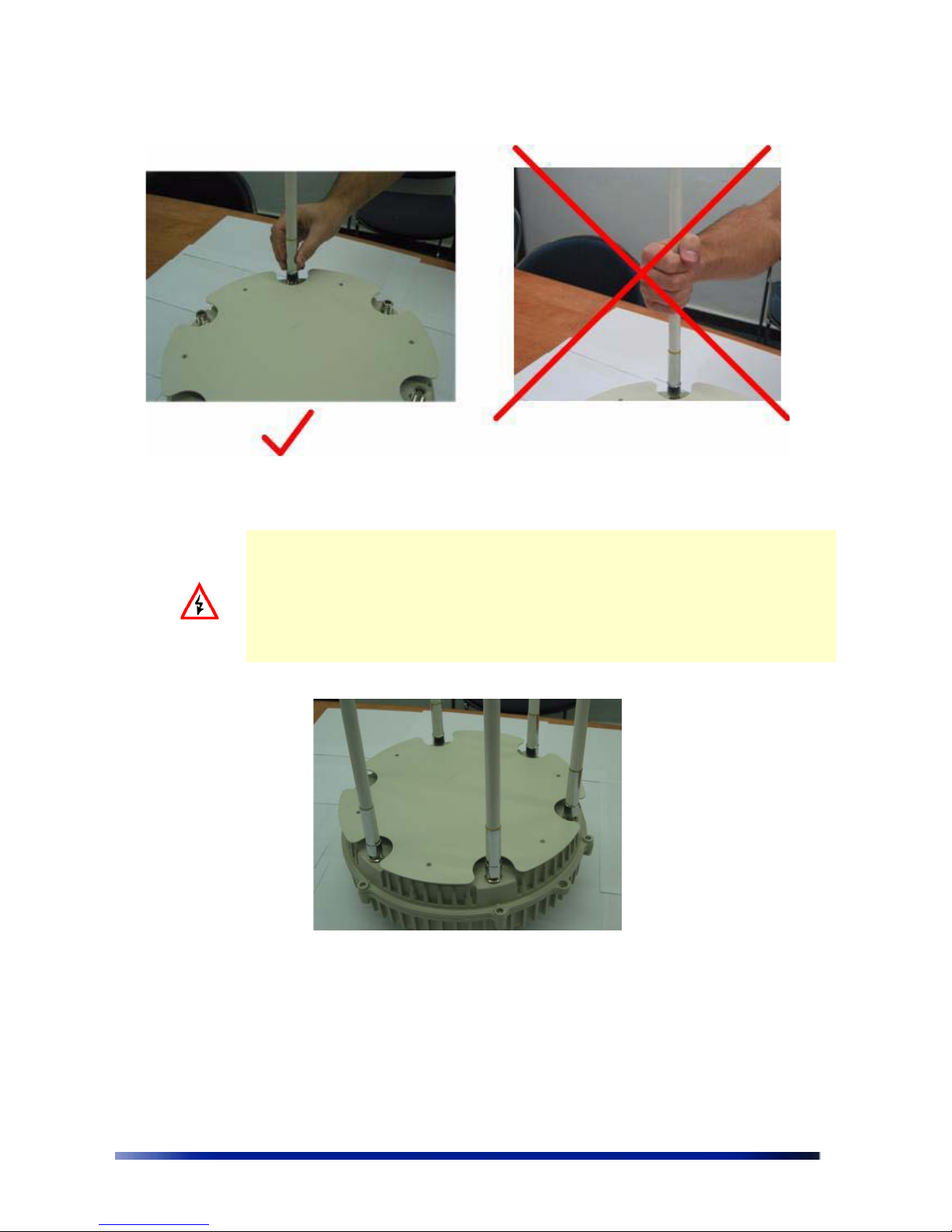
This section explains how to connect the six antennas to the NPP 6X2.4. In order for the
NPP 6X2.4 to work properly, six antennas must be connected.
Screw each of the 6 antennas into the an N-Type connectors on the NPP 6X2.4.
Page 28
28 Netronics Networks
Figure 3.18 Connecting the Antennas
WARNING: Only connect the unit to the power supply once all the antennas are
connected.
WARNING: Use caution when connecting the antennas. Undue haste can damage the
unit.
WARNING: Do not screw in the antenna when holding the top section of the antenna.
You will most likely damage the antenna.
The successful insertion of six antennas should look as follows.
Connecting Power
The following describes how to connect the NPP 6X2.4 to power. There are three options for
connecting the Netronics NPP 6X2.4 to a power source:
• AC power source (3-wire service) -- 3W(P+N+PE) or 3W(2P+PE); 110-220 VAC, 50/60 Hz.
See Installation Accessories on page 49 for details.
Page 29

Installation Guide 29
• NEMA plug, for streetlight photoelectric control power tap (2-wire service) --2W(2P) or
2W(P+N); 100-240 VAC 50/60 Hz. See Installation Accessories on page 49 for details.
• DC power source (2-wire service); 48VDC See Installation Accessories on page 49 for
details.
• Netronics injector connected to Ethernet port B (ETH B). See Installation Accessories on
page 49 for details.
WARNING: Turn the power off before working on an electrical circuit. Turn off the
breaker to the circuit you plan to work on. Post a sign on the service panel so nobody
tries to reconnect power while you are working on the circuits. Double-check the
circuit with a circuit tester before you touch it to make sure the correct breaker has
been disconnected.
Caution: You must always install an external grounding wire. Perform a simple
continuity check between the NPP 6X2.4 and the ground termination point to
confirm. You must also ground the outdoor data protection device to a ground rod
or a bonded pipe. Make sure you have completed grounding before you connect
power to the NPP 6X2.4.
Connecting to AC Power (Category C)
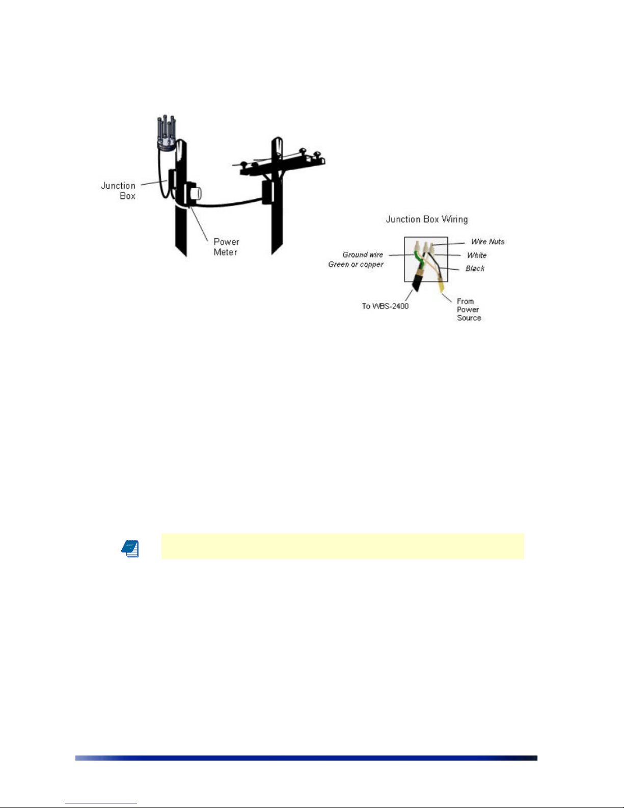
The AC power connections for a Category C AC power source are shown in Figure 3.19.
WARNING: All wiring should be performed by a licensed electrician. All wiring and
connections must conform to local uniform building codes
Page 30
30 Netronics Networks
Figure 3.19 Connecting Category C AC Power
To connect an AC power source:
1. Verify that the service voltage is the following:
NEMA plug, for streetlight photoelectric control power tap (2-wire service) --2W(2P)
or 2W(P+N); 100-240 VAC 50/60 Hz. See Installation Accessories on page
49 for
details.
2. Make sure the power is turned off on the designated circuits.
3. Install a 1/2 inch liquid-tight conduit from the building entrance point to within 3 feet of
the outdoor system.
4. Run 3-wire AC service through the conduit.
5. Connect the conduit to a junction box. The conduit and junction box must be IEEE/ANSI
compliant and suitable for outdoor use.
Note: Data and power must not be enclosed in the same conduit.
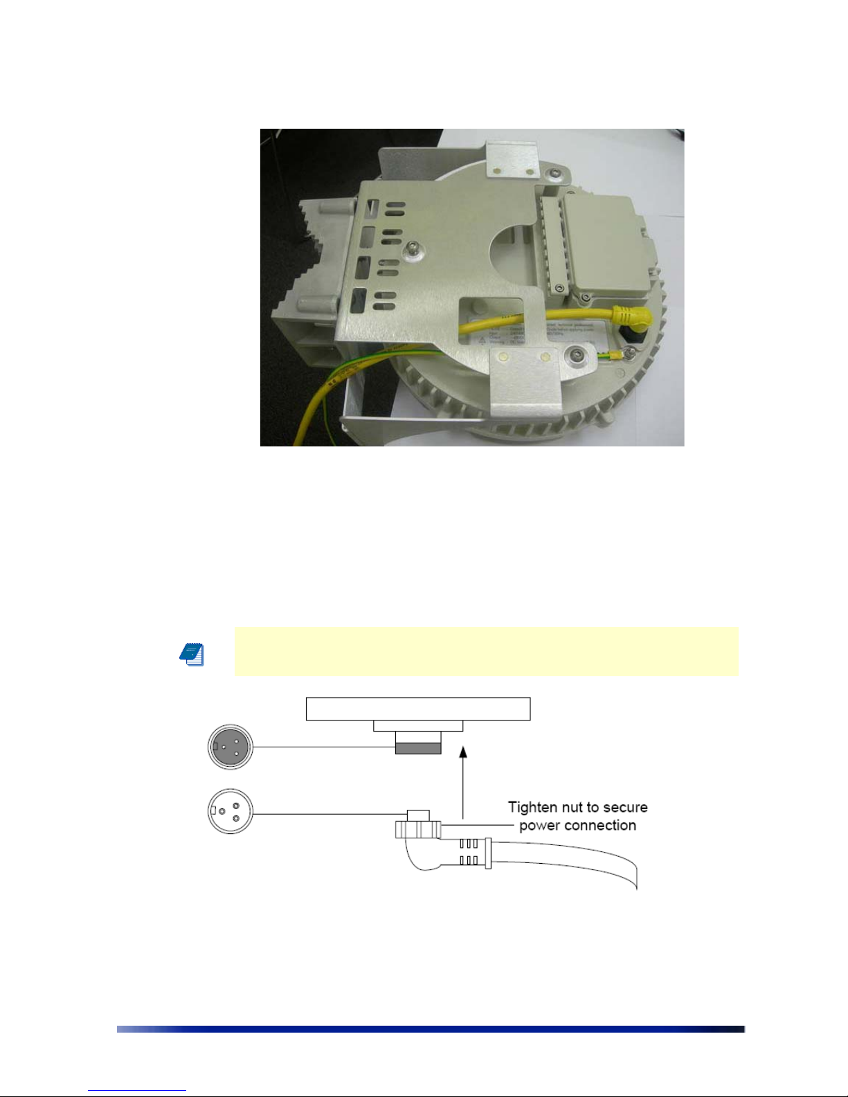
6. Connect the AC cable to the NPP 6X2.4 and tighten the nut.
Page 31
Installation Guide 31
7. Connect the Netronics NPP 6X2.4 to one of the following power sources:
• AC power source (3-wire service) -- 3W(P+N+PE) or 3W(2P+PE); 110-220 VAC,
50/60 Hz. See Installation Accessories
on page 49 for details.
• NEMA plug, for streetlight photoelectric control power tap (2-wire service) --2W(2P)
or 2W(P+N); 100-240 VAC 50/60 Hz. See Installation Accessories on page 49 for
details.
• Reenergize the circuit and check that the power to the NPP 6X2.4 turns on.
Note: The Netronics NPP 6X2.4 is equipped with additional AC surge protection
and fuse branch circuit protection. AC current protection of 20Amp should be
installed
Connect
the AC
cable
Page 32
32 Netronics Networks
Figure 3.20 Connecting the AC Power Cable
Connecting to Streetlight Power (Category C)
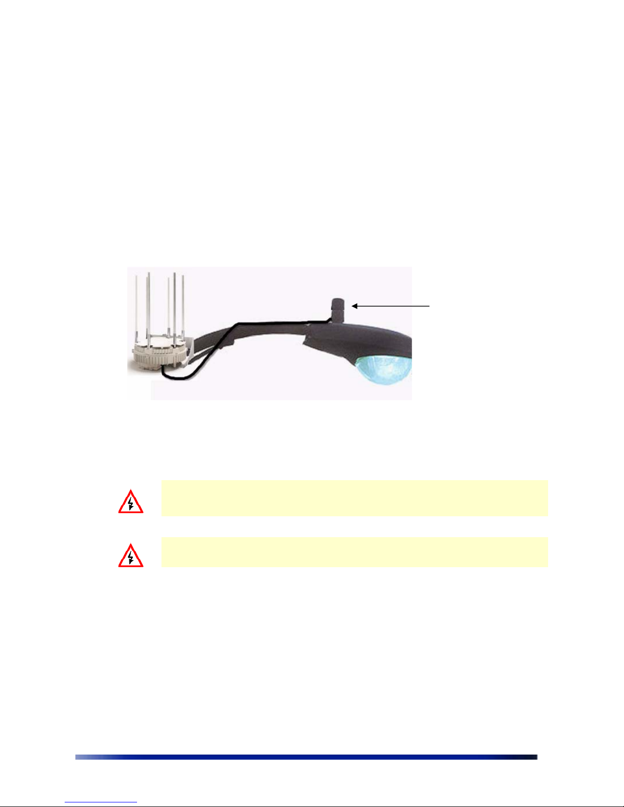
The following describes the power connections for Category C streetlight power. For outdoor
lighting commonly used by utilities, use the 3-prong NEMA twist-lock adapter with twist-lock
style photoelectric controls. The street light adapter uses a 3-pronged NEMA twist-lock adapter
that is installed between the outdoor lighting control and its fixture. The NEMA twist-lock
adapter is designed to be used with UL 773 listed outdoor lighting controls operating with the
following:
NEMA plug, for streetlight photoelectric control power tap (2-wire service) --2W(2P) or
2W(P+N); 100-240 VAC 50/60 Hz. See Installation Accessories on page 49 for details.
Figure 3.21 Connecting Streetlight Power
WARNING Connect the NPP 6X2.4 only to a twist-lock style outdoor lighting control
powered by 100-240 VAC 50/60 Hz. Do not connect it to twist-lock style outdoor
lighting controls powered by higher voltage.
WARNING Be extremely careful when connecting to Category C streetlight power
To connect a streetlight power source:
1. Verify that the service voltage is the following:
• NEMA plug, for streetlight photoelectric control power tap (2-wire service) --2W(2P)
or 2W(P+N); 100-240 VAC 50/60 Hz. See Installation Accessories
on page 49 for
details.
2. Make sure that the power is turned off on the designated circuits.
3. Remove the photosensor from the streetlight.
AC Power from
power adapter on
photosensor
Page 33
Installation Guide 33
4. Connect the NEMA 3 prong plug from the Netronics NPP 6X2.4 to the photosensor
connector on the streetlight.
5. Connect the photosensor to the top of the NEMA 3 prong plug.
6. Connect the AC plug to the NPP 6X2.4 and tighten by hand.
7. Reenergize the circuit and confirm that the power to the NPP 6X2.4 comes on.
Note: The Netronics NPP 6X2.4 is equipped with additional AC surge protection
and fuse branch circuit protection. AC current protection of 20Amp should be
installed.
Note: Do not leave connectors open to the environment. Cover connectors with
the closure cap when not in use and tighten the cap. See Installation Accessories on
page 49
Connecting to DC Power
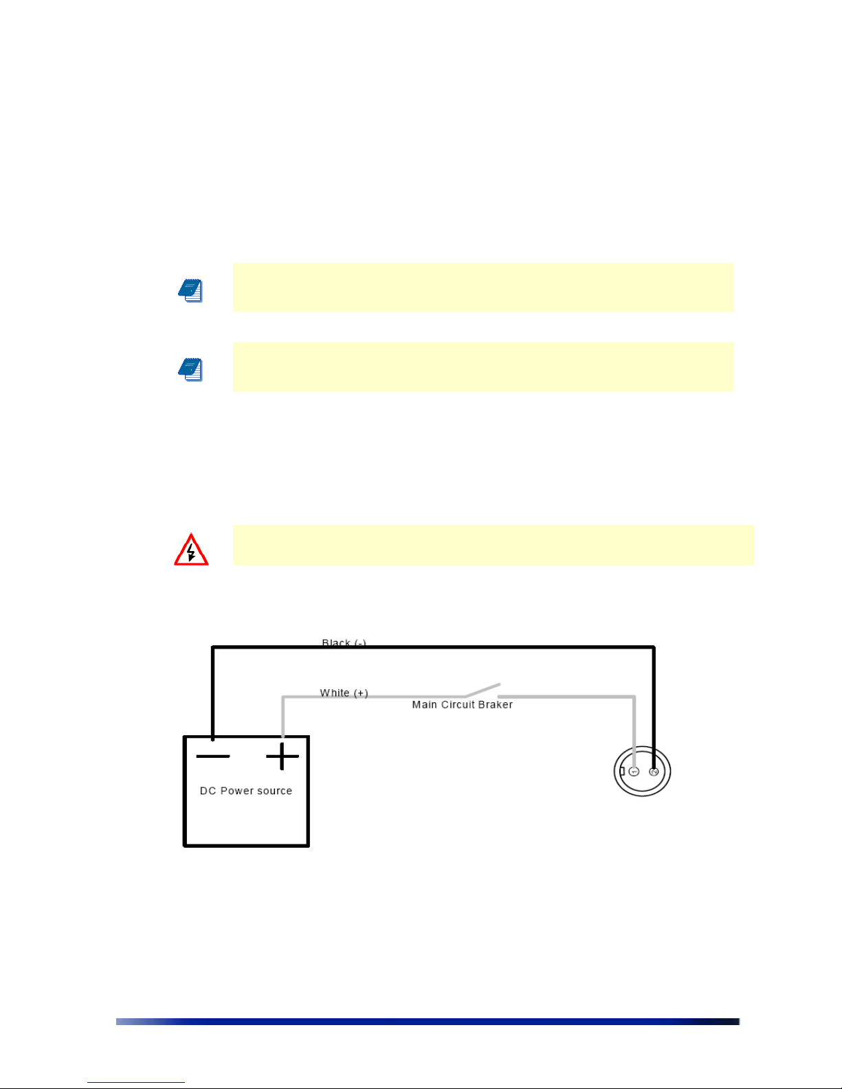
The DC power connections for a DC power source are shown in The Figure.
WARNING All wiring should be performed by a licensed electrician. All wiring and
connections must conform to local uniform building codes.
Figure 3.22 Connecting DC Power
To connect a DC power source:
1. Verify that the service voltage is the following: 48VDC in the correct polarity.
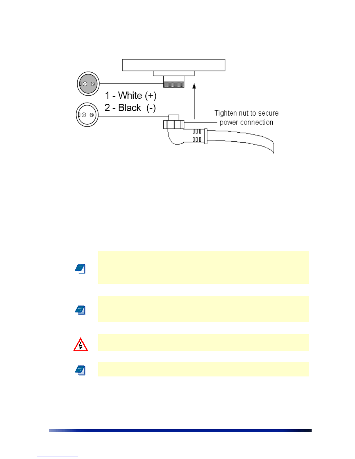
2. Connect positive Voltage to White wire of the DC cable.
Page 34
34 Netronics Networks
3. Connect Negative Voltage to Black wire of the DC cable.
4. Make sure the power is turned off on the designated circuits.
5. Install a 1/2 inch liquid-tight conduit from the building entrance point to within 3 feet of
the outdoor system.
6. Run 2-wire DC service through the conduit.
Note: Data and power must not be enclosed in the same conduit
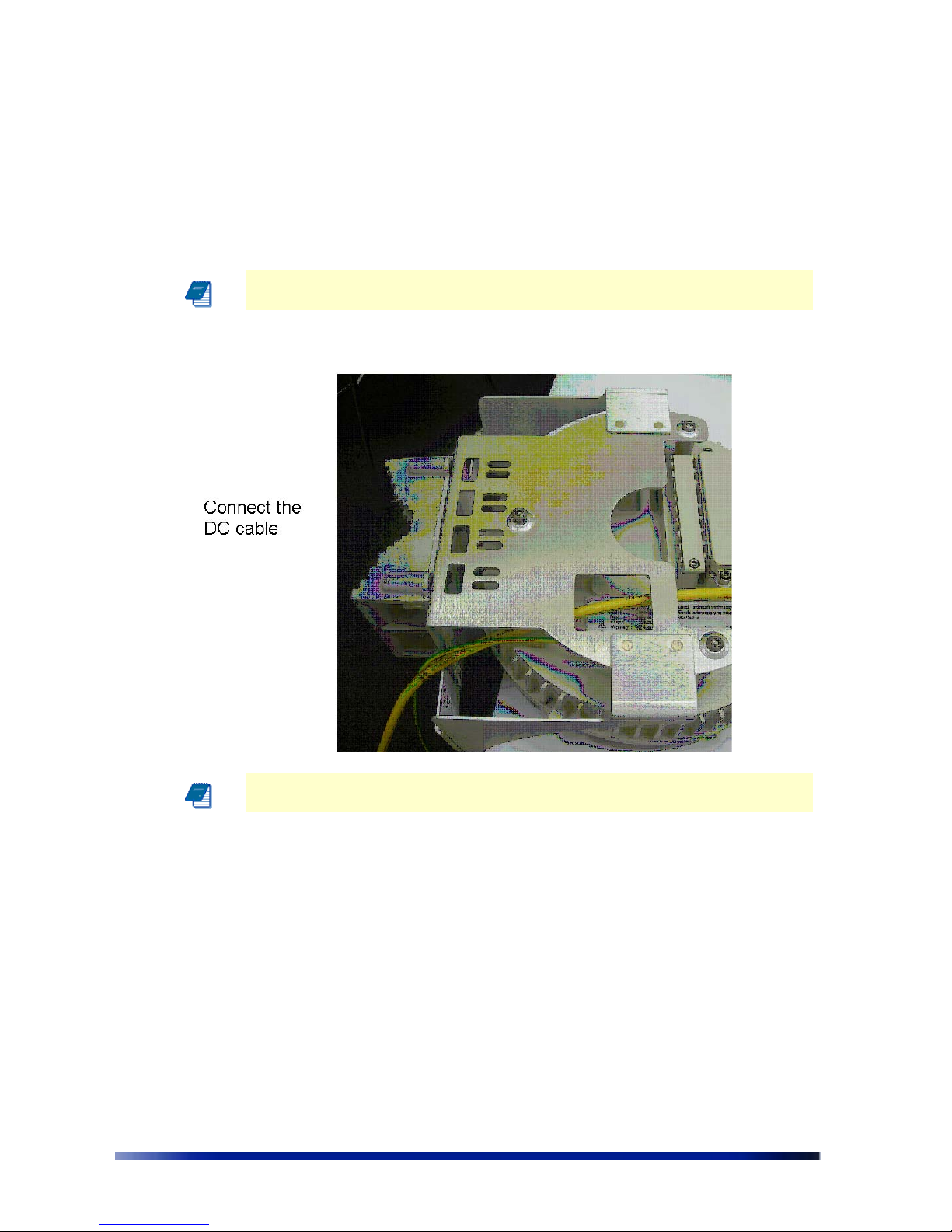
7. Connect the DC cable to the NPP 6X2.4 and tighten the nut.
8. Reenergize the circuit and check that the power to the NPP 6X2.4 turns on.
Note: The Netronics NPP 6X2.4 is equipped with fuse branch circuit protection.
External DC current protection of 10Amp should be installed.
Page 35
Installation Guide 35
Figure 3.23 Connecting the DC Power Cable
Connecting a Data Port
The Netronics NPP 6X2.4 is equipped with four RJ45 connectors. The left hand port named
"SERIAL" is for engineering use only (!). Use the ETH A port if you are connected to the
external unit (backhaul, camera, and etc.) for which you have to supply 12/24VDC power. Use
the ETH B port if you are connected to external unit for which you have to supply 48VDC
power. In case you do not need to power an external device you can connect either ETH A,
ETH B, or ETH C ports. All three Ethernet ports can be active simultaneously.
Note: Use only shielded Cat5e cable rated for outdoor use. See Installation
Accessories on page 49 for details. The shields of the Cat5 cable must be properly
terminated and bonded to the unit and to the protective earth (PE) at the building
entrance. This provides protection against the risk of fire, electrical hazard and
ensures the reliable operation of this equipment.
Note: National Electrical Codes (NEC) Article 800 requires the use of an Agency
Listed (UL/CSA) Building Entrance Protector for all power and communications
cables entering a building. Article 800 is intended to protect the building and
occupants from fires caused by transient voltage and current surges.
WARNING DC voltage may be present on Ethernet A and Ethernet B pins 4,5 (+)
and 7,8 (-)
Note: This is not a mid-span powered device. Do not attempt to daisy-chain
Power Over Ethernet devices.
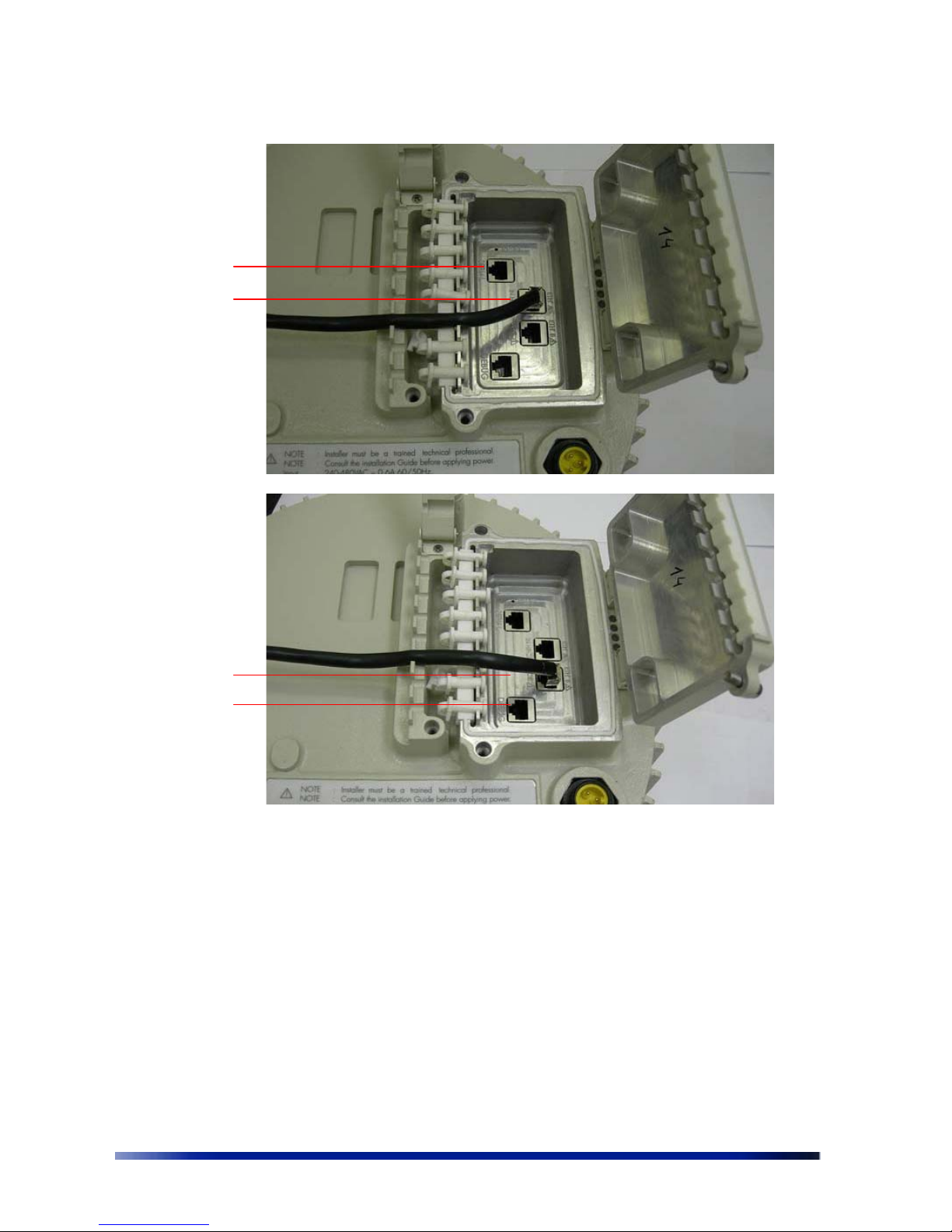
The figures below show the options for routing cables to the Netronics NPP 6X2.4. Connect the
Ethernet cable to the appropriate data port (ETH A, ETH B, or ETH C).
Page 36
36 Netronics Networks
Figure 3.24 Data Port Connection Options
When connecting to the Ethernet port, if you need to terminate the Ethernet cable, use a
standard RJ45 termination. Use a shielded RJ45 plug and be sure to connect the shield of the
Ethernet cable to the shield of the RJ 45 plug.
To connect to the data port:
1. Make sure that the power is turned off for the designated circuits.
2. Run shielded Category 5 Ethernet cable appropriate for outdoor use from a data
protection unit to the Netronics NPP 6X2.4.
3. Connect one end of the Category 5 cable to the data protection unit.
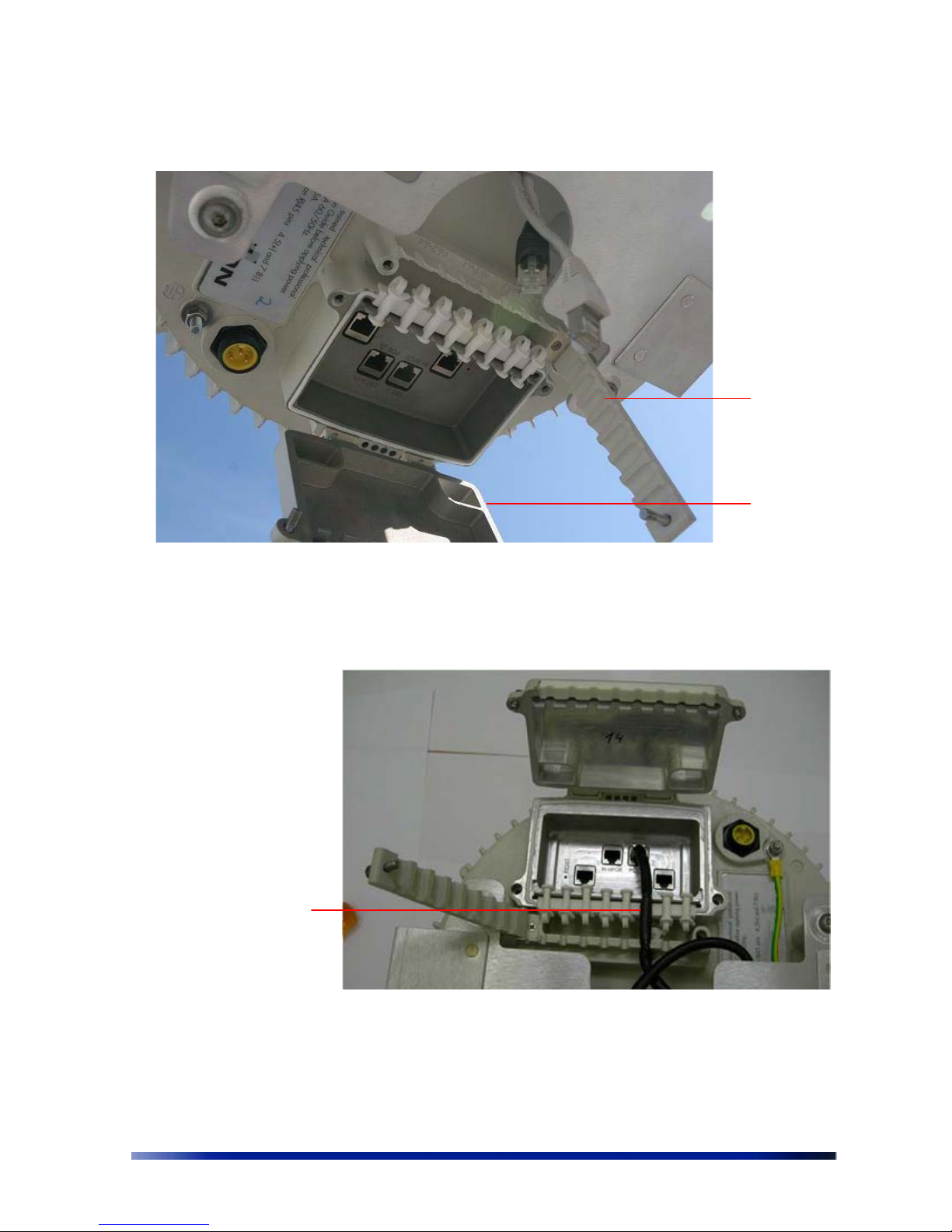
4. Open the connector access cover on the bottom of the NPP 6X2.4 by unscrewing the
two bolts.
ETH A port
ETH B port
ETH C port
SERIAL port
Page 37
Installation Guide 37
5. Open the strip next to the connector access cover by unscrewing the bolt.
Figure 3.25 Opening the Strip and Connector Access Cover
6. Select the slot that matches the diameter of the Ethernet cable and remove the rubber
plug.
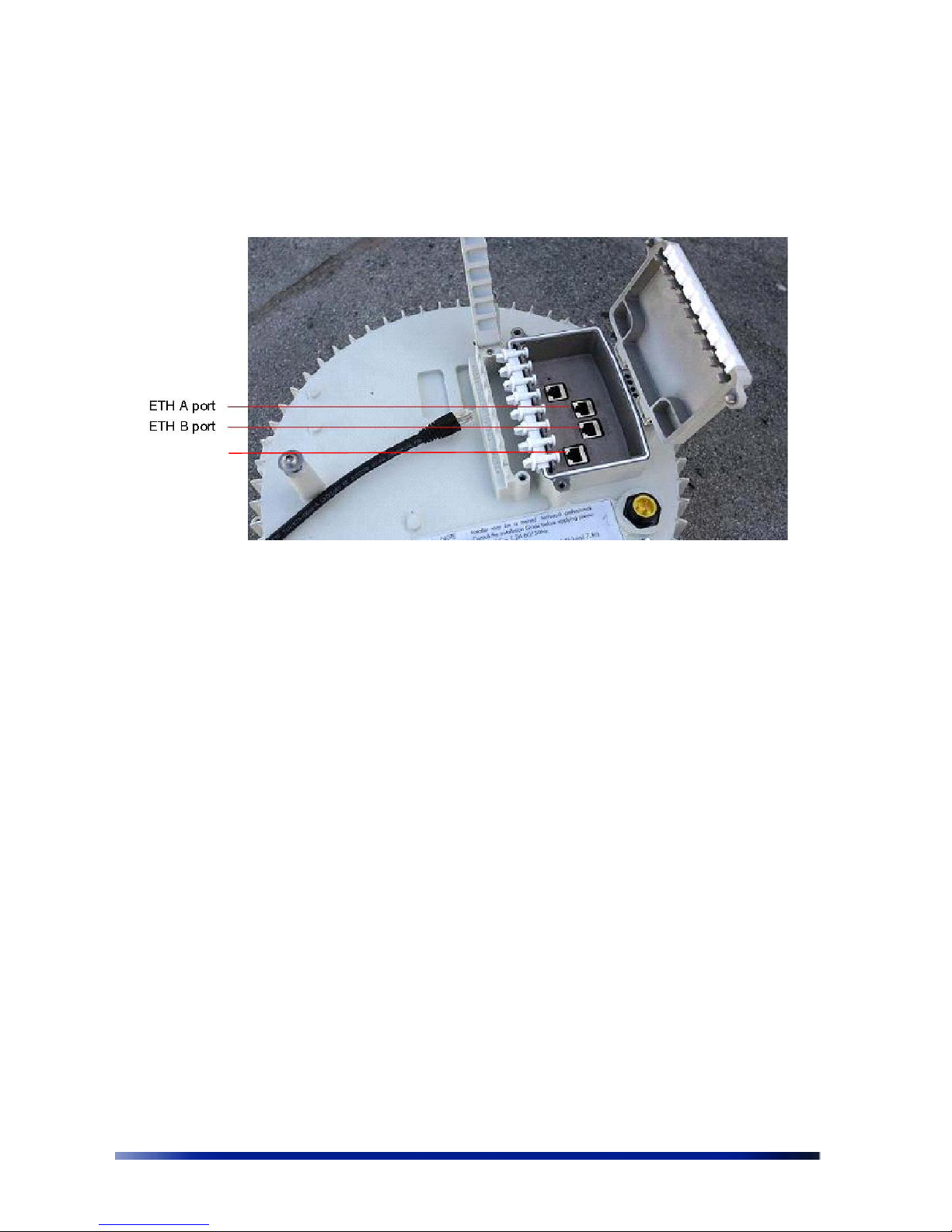
Figure 3.26 Removing the Plug Matching the Diameter of the Cable
Strip
Connector
access cover
Select and
remove plug with
matching
diameter to the
Ethernet cable
Page 38
38 Netronics Networks
7. Connect the cable ends on the NPP 6X2.4 to the ETH A, ETH B, or ETH C ports. Use a
shielded RJ45 8-pin modular plug to terminate the cables at the desired lengths.
8. The port named "DEBUG" is functioning as ETH C port.
9. Make sure that the protection unit is properly grounded.
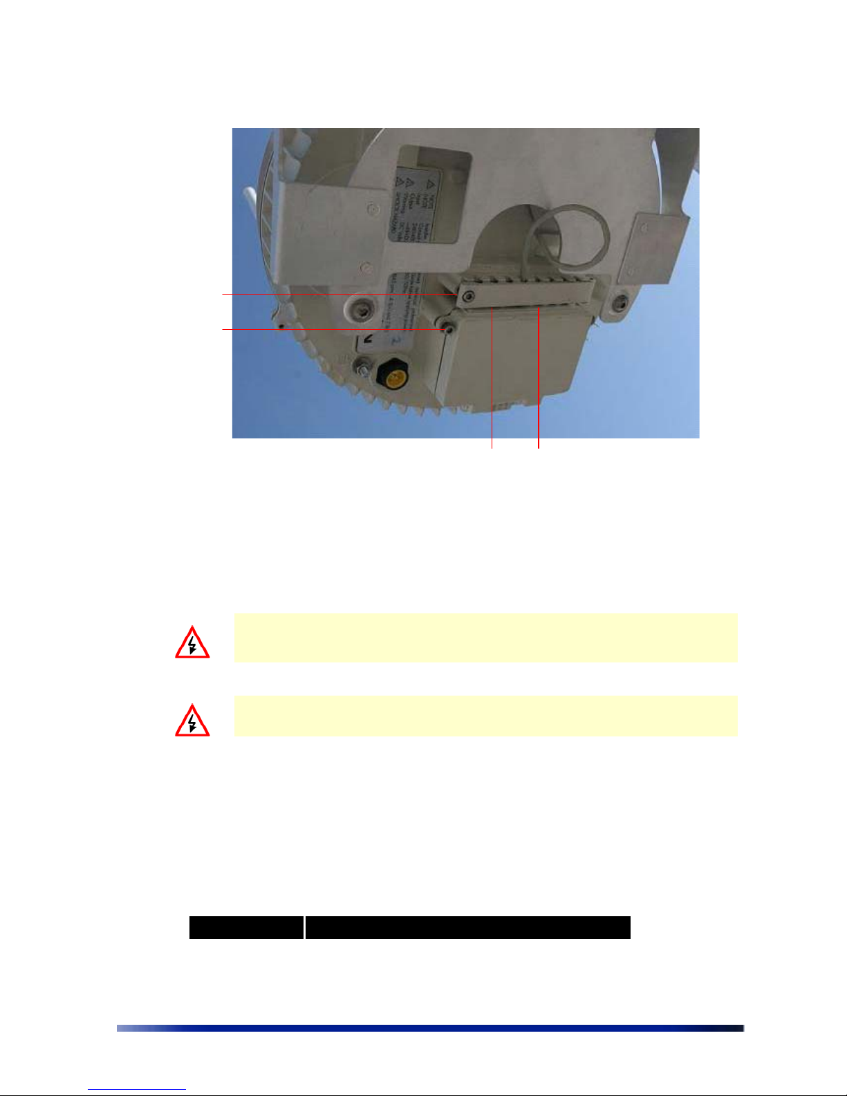
10. Apply silicon across the rubber plugs.
11. Close the strip and tighten the bolt using the 4mm Allen wrench.
12. Close the connector access cover and tighten the bolts using the 4mm Allen wrench.
This ensures a watertight seal.
13. Apply silicon in the gap between the strip and the connector access cover.
ETH C port
Page 39
Installation Guide 39
Figure 3.27 Closing the Covers
14. Create a drip loop of at least 10 inches by looping the cables back to the tray and using
a tie wrap to secure.
WARNING: If you are using a Netronics Injector, make sure you are not supplying
power to the injector until you insert the RJ45 connector into its socket, or you
may risk electric shock.
WARNING: The port named "SERIAL" is for engineering use only. In any case do
not connect PoE source to "SERIAL" port (!)
Connecting Peripherals
The NPP 6X2.4 can source 24VDC or 12VDC powe r on ETH A and 48VDC power on the ETH B
connectors on pins 4, 5 and 7, 8. This allows the NPP 6X2.4 to power an external device.
PoE Power Sourcing Power Output
Voltage Max Power Output
48VDC 30W
Close strip
Close
connector
access cover
Apply silicon
Page 40
40 Netronics Networks
24VDC (available in
future models)
24W
12VDC (available in
future models)
12W
WARNING: Table above defines maximum output power in case that only one of
two ports (ETH A or ETH B) is sourcing power to the external device. If both ports
are powering the external device the total output power should not exceed 30W.
Note: The output power support is available on selected models. Please refer to
Appendix A: NPP 6X2.4 Product list on page 64
Note: PoE output can only be supported if the NPP 6X2.4 is powered by AC or DC
voltage input.
Note: Use only shielded Cat5e cable rated for outdoor use. See Installation
Accessories on page 49 for details. For protection against risk of fire, electrical
hazard and to ensure the reliable operation of this equipment, the shields of the
Cat5 cable must be properly terminated and bonded to the unit and to the
protective earth (PE) at the building entrance.
ETH A and ETH B RJ45 Pin Descriptions for Data Connection
Pin T/R Signal Color Description
1 T TXD+ Orange-White TX Data 10/100BaseT
2 R TXD- Orange TX Data 10/100BaseT
3 T RXD+ Green-White RX Data 10/100BaseT
4 R PoE+ Blue Power output, 12/24/48 VDC (+)
5 T PoE+ Blue-White Power output, 12/24/48 VDC (+)
6 R RXD- Green RX Data 10/100BaseT
7 T PoE- Brown-White Power output, 12/24/48 VDC (-)
8 R PoE- Brown Power output, 12/24/48 VDC (-)
Using a Backhaul Unit
If the installation location does not provide a place to connect to the internet (for example, on
an electricity pole), you need to use a backhaul unit.
There are two types of backhaul units:
• A backhaul unit that provides its own power
• A backhaul unit that uses power supplied by the NPP 6X2.4
Page 41
Installation Guide 41
Note: The antennas on the NPP 6X2.4 must be higher than the antennas on the
backhaul unit.
The following backhaul unit can be powered by the NPP 6X2.4:
• Motorola Canopy uses 24VDC PoE input voltage. Please use the correct NPP 6X2.4 product
version to power the Canopy unit.
• Netronics VL uses 48VDC PoE input voltage (Please refer to Installation Accessories on page
49 for details on connecting the Netronics unit to the NPP 6X2.4)
WARNING: Make sure the backhaul unit has the correct voltage appropriate for
the installation.
Note: When using a backhaul unit that uses power supplied by the NPP 6X2.4,
connect the Ethernet cable to either ETH A or ETH B.
Note: When using a Netronics injector, the NPP 6X2.4 cannot supply power to the
backhaul unit.
Note: Make sure to use the correct part number for the backhaul unit to avoid
causing damage to the unit.
Safety Information for the Netronics NPP 6X2.4
The Federal Communications Commission (FCC) with its action in ET Docket 96-8 has adopted a
safety standard for human exposure to RF electromagnetic energy emitted by FCC certified
equipment. Proper operation of the Netronics NPP 6X2.4 according to the
instructions found in
this manual results in user exposure that is substantially below the FCC recommended limits.
Follow these guidelines to ensure safe operation of the Netronics NPP 6X2.4:
• Do not touch or move the antennas while the unit is transmitting or receiving.
• Make sure the antennas are connected when operating the radio or attempting to transmit
data, otherwise, the radio may be damaged.
• Do not hold the antenna to be close to or touching any exposed parts of the body, especially
the face or eyes, while transmitting.
• The use of wireless devices on airplanes is governed by the Federal Aviation Administration
(FAA).
• The use of wireless devices in hazardous locations is limited to the constraints posed by the
safety directors of such environments.
Page 42

42 Netronics Networks
• The use of wireless devices in hospitals is restricted to the limits set forth by each hospital.
• Do not operate a portable transmitter near unshielded blasting caps or in an explosive
environment.
• The Netronics NPP 6X2.4 must be used only with Netronics approved components and
antennas.
Service Instructions
The Netronics NPP 6X2.4 contains no user serviceable parts inside.
Page 43

Installation Guide 43
Page 44

44 Netronics Networks
Chapter 4
Power Consumption
This chapter describes the power consumption details for the NPP 6X2.4. The power
consumption of the NPP 6X2.4 varies according to the operational conditions and data
transmission rates.
The table below shows the overall maximum power consumption under different conditions.
NPP 6X2.4 Input
Voltage
NPP 6X2.4 Input
Power when PoE
output is not used
NPP 6X2.4 Input
Power when PoE
output is not used
NPP 6X2.4 (Max) Input
Power when a 48VDC
PoE output is used
110 VAC 50/60 Hz 40W 72W 74W
220 VAC 50/60 Hz 44W 78W 81W
Page 45

Installation Guide 45
Chapter 5
Product Specification
The tables in this chapter contain specifications for the N etronics NPP 6X2.4.
Wireless Specifications
IEEE 802.11b/g compliant
Frequency band 2.4 - 2.483 GHz
Modulation
• 802.11b: DSSS (DBPSK, DQPSK, CCK)
• 802.11g: OFDM (64QAM, 16QAM, QPSK, BPSK)
TX Power Maximum 802.11b and 802.11g
Beamformer Directed
Power
EIRP + Beamfroming gain: 42.5dBm
EIRP Calculations
Antenna Gain - 7.5 dBi
Total EIRP - 34.5 dBm
RX Sensitivity* 802.11b and 802.11g
Antenna Array Six 7.5dBi omni-directional antennas
* RX Sensitivity
-105.5 dBm @ 1 Mbps
-103 dBm @ 2 Mbps
-100.5 dBm @ 5.5 Mbps
96 dBm @ 11 Mbps
-102.5 dBm @ 6 Mbps
-100.5 dBm @ 9 Mbps
-99.5 dBm @ 12 Mbps
-98 dBm @ 18 Mbps
-95 dBm @ 24 Mbps
-92 dBm @ 36 Mbps
-88 dBm @ 48 Mbps
-86 dBm @ 54 Mbps
Page 46

46 Netronics Networks
Networking and QoS Specifications
Full 802.11b/g client compatibility
16 VLANs
16 SSIDs
Security Specifications
Packet filtering via layer 2 & 3
WEP (64 bit or 128 bit)
WPA:
Encryption: WEP or TKIP
Authentication: Pre-Shared Key or 802.1x with RADIUS Server (EAP-TLS, PEAP, EAP-TTLS)
VPN pass-through and tagging
HTTPS for web-based management tools
Management Specifications
Web based configuration and management too
SNMPv2 with standard and Netronics MIB support
Configuration save and restore
Network and client statistics
Physical Specifications
Network Interfaces
• Auto-sensing 10/100 Ethernet
• Input from Netronics Injector
Auxiliary Network Interface
• For connection to a backhaul interface where PoE to the
backhaul device is required.
• Auto-sensing 10/100 Ethernet
• Input/Output Po wer over Ethernet
Power Input
• Weather-tight power connector plug for 100-240 VAC power
input
• Power from a Netronics Injector (ETH B port only)
Indicator Lights
• Two Ethernet port LED Link/Act indicators (only for ETH A
and ETH B ports)
• System Status LED indicator
• RF channel status indicator
Physical Dimensions
Base:
• Diameter - 13in (33cm)
Page 47

Installation Guide 47
• Height - 5in (12cm)
Antenna Array:
• Height - 17in (43cm)
Weight: 20lbs (8kg)
Power Specifications
Power Input
• 100 - 240 VAC weather-proof power cable, 50/60 Hz with
standard AC connector or street light NEMA photo-electric control
power tap
• 55VDC, supplied over Ethernet from Netronics injector.
Input Power
Consumption
• Power from Netronics Injector 35W @ 55VDC
• For AC input see
Power Consumption on page 44
Output Power over
Ethernet Option
For powering an external device:
• 48VDC, 0.6A max.
• 24DC, 1A max.
• 12VDC, 1A max.
• The output power from both ETH A and ETH B ports must NOT
exceed 30W.
Environmental Specifications
Operating Temperature Range -40°C to +55°C
Storage Temperature Range -45°C to +85°C
Weather Rating IP65
Wind Survivability 165 mph
Salt and Fog Rust Resistance MIL-STD-810F 509.4
Shock and Vibration ESTI 300-192-4 spec T41.E
Transportation ISTA2A
Approvals
RF FCC CFR part 15, Class C
Safety TUVus
EMC 47 CFR Part 15, Sub Part B, Class B (USA)
Page 48

48 Netronics Networks
Page 49

Installation Guide 49
Chapter 6
Installation Accessories
This chapter describes the accessories available for the NPP 6X2.4 and ordering information.
The following topics are covered in this chapter:
• Power Cable on page 50
•
Ethernet Cables on page 50
•
Lightning Protection on page 50
•
Power Over Ethernet on page 50
•
Client Connectivity on page 50
Page 50

50 Netronics Networks
Power Cable
Description Part Number
Power Cable for Netronics Base Station,, 110-240 VAC, 20 feet (Unterminated) WPC-AC-6M-UNV
Street Light Power Tap for Netronics Switch 410, 110/220 VAC, 30 feet WPC-SLP-9M
Street Light Power Tap for Netronics Switch 410, 110/220 VAC, 6 feet WPC-SLP-2M
Closure Caps for Plugs and Receptacles. An all-weather cover/cup for the AC power
connector, to be used when no AC power is required
WPC-CUP-AC
Power Cable for Netronics Base Station, 48 VDC, 6 feet. WPC-DC-6M-UNV
Ethernet Cables
Description Manufacturer
Part
Number
Distributor
Contact
Information
Order
Number
Outdoor CAT5 4-pair data
cable
Belden 7929A Anixter www.anixter.com
Outdoor CAT5e double jacket
4-pair data cable
Teldor 8393204101 G.Bares www.teldor.com
Lightning Protection
Description Manufacturer
Part
Number
Distributor Contact Information
Order
Number
Data protection
device
Hyperlink HGLN-CAT5-1
www.hyperlinktech.com
Power Over Ethernet
Description Part Number
Netronics Injector for powering the NPP 6X2.4 over an Ethernet cable. Output 55VDC, 1A. WPI-AC-55W
Client Connectivity
Description Manufacturer
Netronics - Use Netronics Indoor-Outdoor CAT 5e cable with pin crossing (pin 5 of the
NPP 6X2.4 PoE connector goes to pin 7 of Netronics RJ45 connector, pin 7 of the NPP
6X2.4 PoE connector goes to pin 5 of the Netronics RJ45 connector)
See Installation
Guide
Motorola (Canopy) - Use outdoor CAT 5e cable with spare pin crossing (pin 4 5 of the
NPP 6X2.4 PoE connector goes to pin 7 8 Motorola RJ45 connector respectively)
Page 51

Installation Guide 51
(pin 7 8 of the NPP 6X2.4 PoE connector goes to pin 4 5Motorola RJ45 connector
respectively)
Page 52

52 Netronics Networks
Page 53
Installation Guide 53
Chapter 7
AC Wiring Diagrams
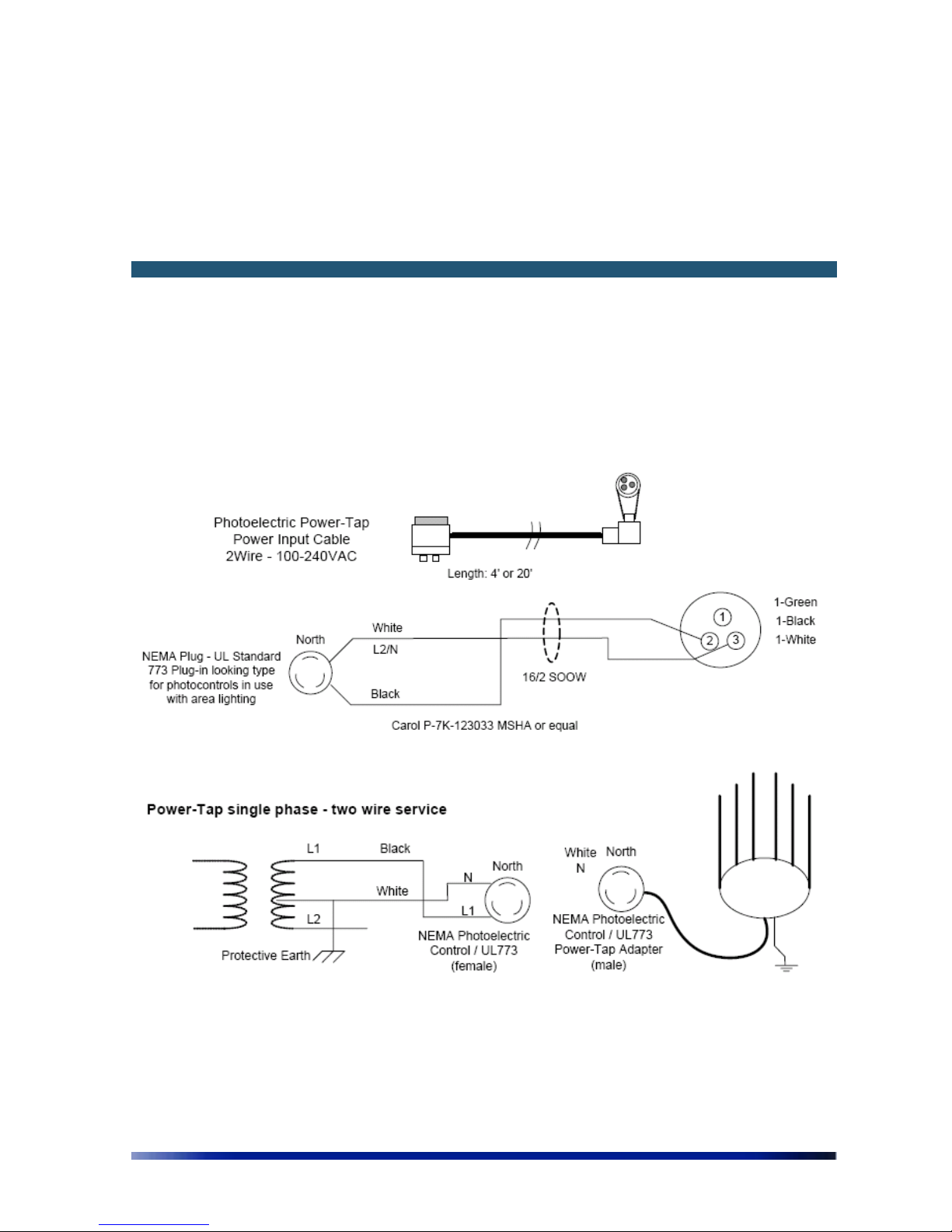
This chapter contains the following wiring diagrams for AC power:
• AC Wiring Photoelectric Power Tap on page 53
•
AC Wiring Power Cable 120VAC, 15A Plug on page 55
AC Wiring Photoelectric Power Tap
NPP 6X2.4
WPC-AC-6M-UNV
Page 54
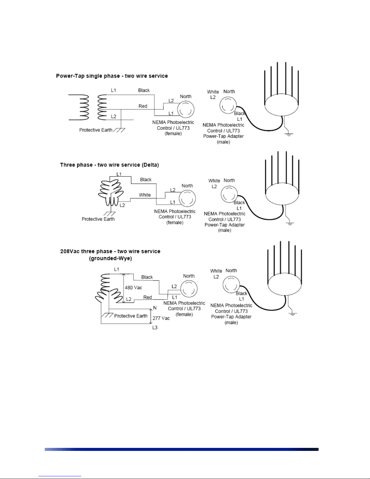
54 Netronics Networks
Figure 8.1 AC Wiring Photoelectric Power Tap
NPP 6X2.4
NPP 6X2.4
NPP 6X2.4
Page 55
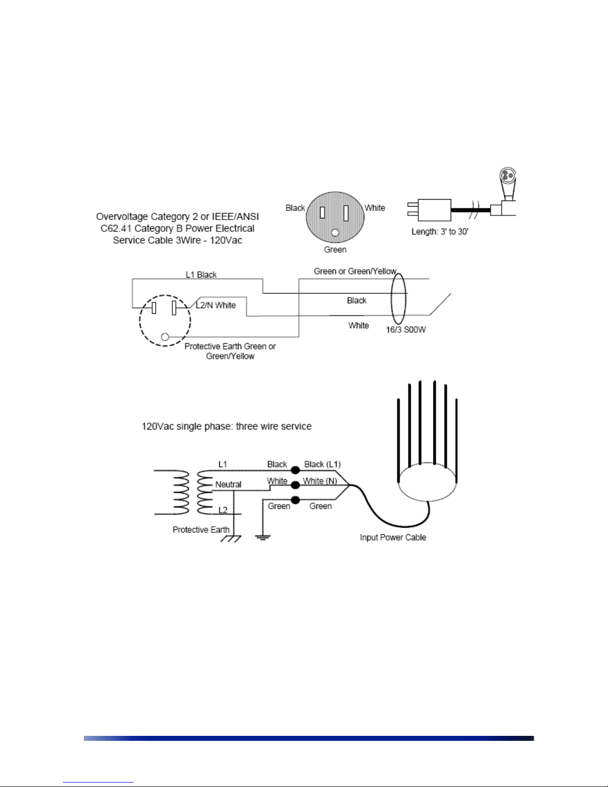
Installation Guide 55
AC Wiring Power Cable 120VAC, 15A Plug
Figure 8.2 AC Wiring Power Cable 120VAC, 15A Plug
NPP 6X2.4
WPC-AC-6M-UNV
Page 56

56 Netronics Networks
Page 57

Installation Guide 57
Chapter 8
Wind Loading Considerations
This chapter describes wind loading considerations for the NPP 6X2.4.
Note: It is recommended to evaluate the static and dynamic load bearing
capabilities for each assembly and installation individually. It is your
responsibility to evaluate the load bearing capabilities of the structure.
The Netronics NPP 6X2.4 weighs approximately 16 lbs, including all mounting hardware. When
the Netronics NPP 6X2.4 is mounted on a pole, the sail area of the NPP 6X2.4 is approximately
1 square foot. The Netronics NPP 6X2.4 can load a pole with a maximum load of 3400 Newton
in wind conditions of 165mph.
Page 58

58 Netronics Networks
Page 59

Installation Guide 59
Chapter 9
Backhaul Unit Installation Instructions
This chapter describes how to install a backhaul unit with the NPP 6X2.4.
Use the assembly equipment provided with the backhaul unit to install. Netronics does not
provide brackets or mounting equipment for the backhaul unit. Make sure the NPP 6X2.4 is
installed in a higher position then the backhaul unit so the antennas are unobstructed. If the
backhaul unit is powered externally, connect to either ETH A, ETH B, or ETH C port. If the
backhaul unit is not powered externally, connect to either ETH A or ETH B port, according to
the backhaul input voltage.
Disconnect power to the NPP 6X2.4 before connecting the backhaul unit
Make sure to use the correct Netronics part number for each backhaul unit
Page 60

60 Netronics Networks
Page 61

Installation Guide 61
Chapter 10
Acronyms
Acronym Description
2P Two-Phase or Split Phase
2W Two-Wire
3W Three-Wire
AC Alternating Current
ANSI American National Standards Institute
AWG American Wire Gauge
C Celsius
CAT Category
CCK Complementary Code Keying
CFR Code of Federal Regulations
CSA Canadian Standard Association
dB Decibels
dBi Decibels Relative to an Isotropic Radiator
DBPSK Differential-Binary Phase-Shift Keying
DC Direct Current
DQPSK Differential-Quadrature Phase-Shift Keying
DSSS Direct-Sequence Spread Spectrum
EMC Electromagnetic Compatibility
EN IEC standard
ESD Electrostatic Discharge
FCC Federal Communications Commission
Hz Hertz
HPoE High Power over Ethernet
IEEE Institute of Electrical and Electronics Engineers
IP67 Ingress Protection Standard
ISTA International Safe Transit Association
LAN Local Area Network
Mbps Megabits Per Second
Page 62

62 Netronics Networks
MHz Megahertz
MIL-STD Military Standard
N Neutral
NEC National Electrical Codes
NEMA National Electrical Manufacturers Association
OFDM Orthogonal Frequency Division Multiplexing
P Phase
PE Protective Earth
PoE Power over Ethernet
RJ45 Registered Jack 45
RSS Received Signal Strength
Rx Receive
RXD Receive Data
TUV Technical Inspection Association
Tx Transmit
TXD Transmit Data
UL Underwriters Laboratories
VAC Voltage (Alternating Current)
VCCI Voluntary Control Council for Interference
VDC Voltage (Direct Current)
W Watts
Page 63

Installation Guide 63
Page 64

64 Netronics Networks
Chapter 11
Appendix A: NPP 6X2.4 Product list
Part Number Product namer Product description
12405101 NPP 6X2.4-POE-FCC
Spatially adaptive, multi radio WiFi base station, PoE input,
no PoE output.
FCC/TUV compliant
12405102 NPP 6X2.4-POE-EU
Spatially adaptive, multi radio WiFi base station, PoE input,
no PoE output.
ETSI / CE compliant
12405201 NPP 6X2.4-AC-48-FCC
Netronics 2.4GHz Spatially adaptive, multi radio WiFi base
station, with 2.4GHz self backhaul. 100-240VAC input and
48VDC PoE output for external device.
FCC/TUV compliant
12405202 NPP 6X2.4-AC-48-EU
Spatially adaptive, multi radio WiFi base station, 100240VAC input and 48VDC PoE output for external device.
ETSI / CE compliant
 Loading...