

Netro RU39G-00 User Manual
4.1 Base S tation Outdoor Instal lation (BRU)
This section describes the procedures for installing a 26 GHz, 39 GHz, and a 10 GHz Base
Radio Unit (BRU).
A BRU Installation Kit is included with the BRU. The BRU Installation Kit contains
connectors for LMR coax cable, self-amalgamating tape, an extra jam nut for the
grounding/lightning protection lug, and a short 1.5m length of LMR240 cable as explained
below.
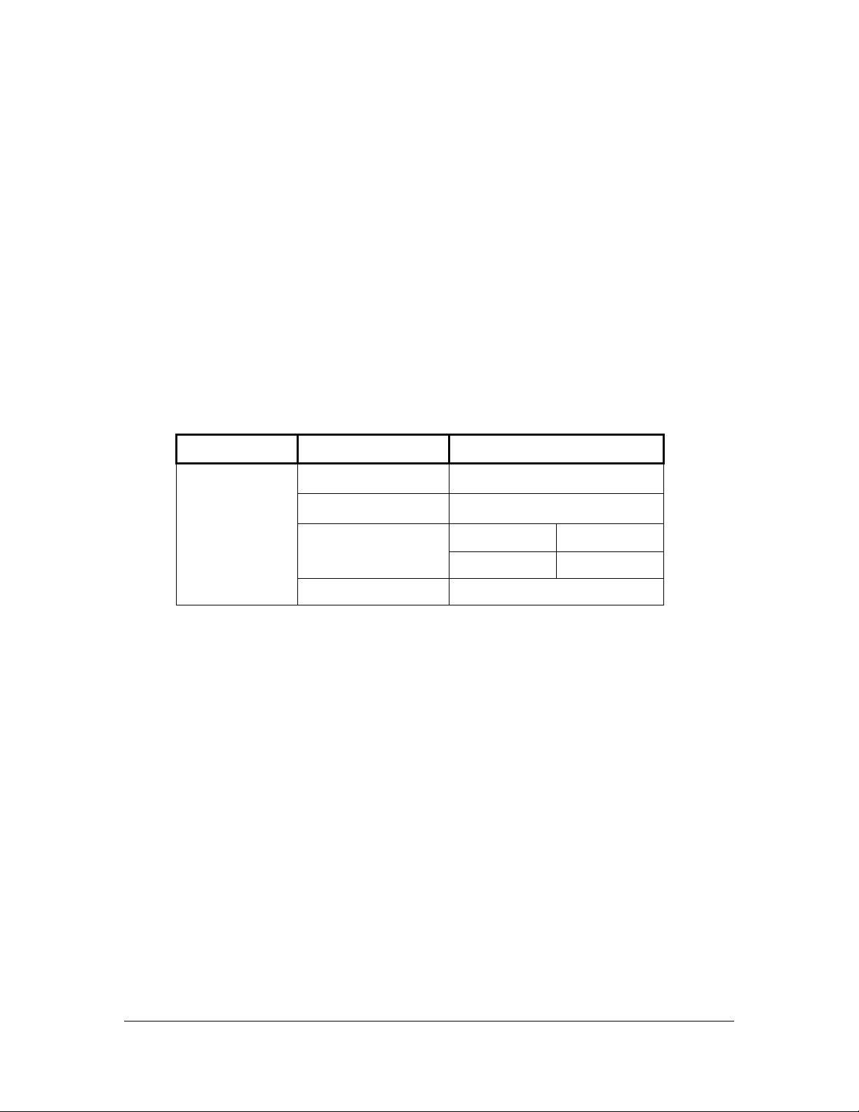
The location, height, elevation angle and azimuth direction of the BRU to be installed is
determined by the network configuration you have selected. Table Error! No text of
specified style in document.-1 shows the operating range for the BRU.
Table Error! No text of specified style in document.-1 BRU Operating En viro nmen tal
Specifications
Type Item Specifications
Environmental
Characteristics
Storage temperature
Operating temperature
Wind loading Operational 145 km/hr
Altitude 0 m to 4500 m
-40
°C to +70°C
-35
°C to +55°C
Survival 200 km/hr
The 26 GHz and 39 GHz BRU antenna is vertically polarized. To preserve the correct
polarization, mount the BRU with the same orientation as shown in the installation figures.
The BRU will not function properly if the polarization is not correct. For proper
polarization the BRU must be within 3
° of vertical.
The 10 GHz BRU can be ordered either vertically polarized or horizontally polarized.
4.1.1
4.1.1 Wind Loading
4.1.14.1.1
Wind Loading
Wind LoadingWind Loading
For the pole mount, the coordinate origin is set in the centerline of the pole, located on
middle of the two bolts in Z axis (not the base of the mounting bracket).
The appendix contains a complete Wind Load analysis report for the BRUs.
AirStar User Guide for Release 2.1.4
15741-1000 Rev. 0.09 03/ 31/ 00
AirStar User Guide for Release 2.1.4
AirStar User Guide for Release 2.1.4 AirStar User Guide for Release 2.1.4
1111

4.1.2
4.1.2 Mounting the 26 GHz or 39 GHz BRU
4.1.24.1.2
Mounting the 26 GHz or 39 GHz BRU
Mounting the 26 GHz or 39 GHz BRUMounting the 26 GHz or 39 GHz BRU
Mount the BRU on a support pole (2 to 4.5 in or 50 to 114 mm in diameter). The only tool
required to mount the BRU is a 17mm wrench. An Installation Kit is provided with the unit.
One or more BRUs may be mounted on the same pole.
Use the following procedure to mounting the BRU on the pole:
Refer to Figure Error! No text of specified style in document.-1 and use the
1.
instructions supplied with the Pole Mounting Kit to assemble the pole mount
prior to installing it on pole.
Orient the mounting plate so that it is at the appropriate height and 90 degrees
2.
from the pointing direction of the BRU (so the BRU points in the correct
direction when mounted) and secure it (do not over tighten). When using the
M10 nuts, start the nut and screw it down close to its final position. Then place a
drop of anti-seize compound on each bolt, making sure to cover the thread near
the final nut position when the nut is tightened.
Figure Error! No text of specified style in document.-1 Inst allin g th e BRU Po le M ou nt
Install the BRU onto the Mounting Plate as follows (see Figure Error! No text
3.
of specified style in document.-2):
a) Insert the two studs with the o-ring, flat washer, lock washer and hex nut
through the clearance holes on the mounting plate.
b) Slide the BRU to the left until the Rotation Pin on the BRU/BRU Mounting
Bracket assembly aligns with the Pilot Hole of the Mounting Plate and the
two studs are in the elevation adjustment slots.
c) Push the BRU/BRU Mounting Bracket assembly flush against the mounting
plate so that the Rotation Pin is in the Pilot Hole. Loosely tighten the nuts
on the two bolts, as shown in Figure Error! No text of specified style in
document.-2 and
d) Figure Error! No text of specified style in document.-3.
e) Adjust the elevation of the BRU. Tighten the two nuts on the BRU to secure
it at the proper elevation. Attach lightning protection using the grounding
lug on the bottom center of the BRU as appropriate.
The Pole Mount has ±15 degree elevation rotation for the BRU.
AirStar User Guide for Release 2.1.4
AirStar User Guide for Release 2.1.4
AirStar User Guide for Release 2.1.4 AirStar User Guide for Release 2.1.4
2222
15741-1000 Rev. 0.09 03/ 31/ 00
 Loading...