

Page 1
1
NetProbe 2000
User Manual
Ver 5.06.02 June 2016
Page 2

2
TABLE OF CONTENTS
TABLE OF CONTENTS ......................................................................................................................................................................... 2
1. WARRANTY AND SOFTWARE .................................................................................................................................................. 13
2. IMPORTANT SAFETY INFORMATION ....................................................................................................................................... 15
3. INTRODUCTION ....................................................................................................................................................................... 16
4. DESCRIPTION .......................................................................................................................................................................... 17
4.1 E
XTERNAL INTERFACES
.................................................................................................................................................................. 17
4.1.1 Top Control Panel ............................................................................................................................................................... 17
4.1.2 Test Interface Signal Panel ................................................................................................................................................. 18
4.1.3 Front Control Panel ............................................................................................................................................................ 19
4.2 G
RAPHICAL USER INTERFACE
(GUI) ................................................................................................................................................ 20
4.3 O
PERATORS REFERENCE
................................................................................................................................................................ 22
4.4 M
AIN MENU
.............................................................................................................................................................................. 23
4.4 T
EST RESULTS
............................................................................................................................................................................. 24
4.5 S
TANDARD ACCESSORIES
............................................................................................................................................................... 29
4.6 O
PTIONAL ACCESSORIES
............................................................................................................................................................... 29
5. E1 ANALYZER OPTION ............................................................................................................................................................. 31
Page 3

3
5.1 T
OP MENU
................................................................................................................................................................................ 31
5.2 S
ET UP
...................................................................................................................................................................................... 32
5.2.1 General Configuration Tab ................................................................................................................................................. 32
5.2.2 Automonitor Configuration Tab ......................................................................................................................................... 38
5.3 A
UTO MONITOR
......................................................................................................................................................................... 43
5.4 B
IT ERROR TESTING
(BERT) .......................................................................................................................................................... 51
5.4.1 ALARM menu ...................................................................................................................................................................... 55
5.4.2 G.821 ERROR menu ............................................................................................................................................................ 56
5.4.3 Live Traffic menu ................................................................................................................................................................ 57
5.5 P
ROPAGATION DELAY MEASUREMENT
(PDL) ................................................................................................................................... 58
5.6 P
ULSE SHAPE ANALYSIS
(PSA) ....................................................................................................................................................... 60
5.6 DS0 T
ESTING
............................................................................................................................................................................. 61
6. T1 ANALYZER OPTION ............................................................................................................................................................. 62
6.1 T
OP MENU
................................................................................................................................................................................ 62
6.2 S
ET UP
...................................................................................................................................................................................... 63
6.2.1 General Configuration Tab ................................................................................................................................................. 63
6.2.2 Automonitor Configuration Tab ......................................................................................................................................... 69
6.3 A
UTO MONITOR
......................................................................................................................................................................... 73
6.4 B
IT ERROR TESTING
(BERT) .......................................................................................................................................................... 80
6.4.1 ALARM menu ...................................................................................................................................................................... 84
6.4.2 G.821 ERROR menu ............................................................................................................................................................ 85
6.4.3 Live Traffic menu ................................................................................................................................................................ 86
6.5 P
ROPAGATION DELAY MEASUREMENT
(PDL) ................................................................................................................................... 87
6.6 P
ULSE SHAPE ANALYSIS
(PSA) ....................................................................................................................................................... 89
Page 4

4
6.7 DS0 T
ESTING
............................................................................................................................................................................. 90
7. T3 ANALYZER OPTION ............................................................................................................................................................. 91
7.1 T
OP MENU
................................................................................................................................................................................ 91
7.2 S
ET UP
...................................................................................................................................................................................... 92
7.3 B
IT ERROR TESTING
(BERT) .......................................................................................................................................................... 96
7.3.1 ALARM menu .................................................................................................................................................................... 100
7.3.2 G.821 ERROR menu .......................................................................................................................................................... 101
7.3.3 Line menu ......................................................................................................................................................................... 102
8. E3 ANALYZER OPTION ........................................................................................................................................................... 103
8.1 T
OP MENU
.............................................................................................................................................................................. 103
8.2 S
ET UP
.................................................................................................................................................................................... 104
8.3 B
IT ERROR TESTING
(BERT) ........................................................................................................................................................ 108
8.3.1 ALARM menu .................................................................................................................................................................... 112
8.3.2 G.821 ERROR menu .......................................................................................................................................................... 113
8.3.3 Line menu ......................................................................................................................................................................... 114
9. CO-DIR ANALYZER OPTION .................................................................................................................................................... 115
9.1 T
OP MENU
.............................................................................................................................................................................. 115
9.2 S
ET UP
.................................................................................................................................................................................... 116
9.3 B
IT ERROR TESTING
(BERT) ....................................................................................................................................................... 118
9.3.1 G.821 ERROR menu .......................................................................................................................................................... 122
9.3.2 Frequency Measurement menu ....................................................................................................................................... 123
9.4 P
ROPAGATION DELAY MEASUREMENT
(PDL) ................................................................................................................................. 124
Page 5

5
10. DATACOM ANALYZER OPTION .......................................................................................................................................... 126
10.1 SETUP ................................................................................................................................................................................... 127
10.2 B
IT ERROR TESTING
(BERT) ....................................................................................................................................................... 132
10.2.1 G.821 ERROR menu ...................................................................................................................................................... 136
10.2.2 Frequency Measurement menu ................................................................................................................................... 137
10.3 P
ROPAGATION DELAY MEASUREMENT
(PDL) ................................................................................................................................. 138
11. IEEE C37.94 ANALYZER OPTION ......................................................................................................................................... 140
11.1 IEEE C37.94 T
ELE-PROTECTION
.................................................................................................................................................. 140
11.2 I
NTRODUCTION
......................................................................................................................................................................... 141
11.3 D
ESCRIPTION
............................................................................................................................................................................ 141
11.4 SETUP ................................................................................................................................................................................... 142
11.5 B
IT ERROR TESTING
(BERT) ........................................................................................................................................................ 144
11.5.1 G.821 ERROR menu ...................................................................................................................................................... 150
11.5.2 ALARM menu ............................................................................................................................................................... 151
11.5.3 Live Traffic menu .......................................................................................................................................................... 152
11.6 O
PTICAL POWER
....................................................................................................................................................................... 153
11.6.1 Optical Power .............................................................................................................................................................. 153
11.6.2 SFP Info ........................................................................................................................................................................ 154
11.7 P
ROPAGATION DELAY TEST
(PDL) ............................................................................................................................................... 155
11.8 C37.94 T
EST RECORDS
.............................................................................................................................................................. 158
12. GIGABIT BASIC ANALYZER OPTION ................................................................................................................................... 160
12.1 I
NTRODUCTION
......................................................................................................................................................................... 160
Page 6

6
12.2 S
ETUP
..................................................................................................................................................................................... 161
12.2.1 SFP Identity ....................................................................................................................................................................... 161
12.2.2 PORT SETUP and PORT STATUS ................................................................................................................................... 162
12.2.3 Network Parameters .................................................................................................................................................... 162
12.3 W
IREMAP
................................................................................................................................................................................ 163
12.3.1 Fundamentals .............................................................................................................................................................. 163
12.3.2 Accuracy ....................................................................................................................................................................... 164
Cable Termination .......................................................................................................................................................................................... 164
Coupling Between Cable Pairs........................................................................................................................................................................ 164
12.4 L
OOPBACK
............................................................................................................................................................................... 166
12.4.1 Filter ............................................................................................................................................................................. 167
12.4.2 Statistics ....................................................................................................................................................................... 168
12.4.3 Running loopback ........................................................................................................................................................ 169
12.5 M
ONITOR
................................................................................................................................................................................ 170
12.5.1 Filter ............................................................................................................................................................................. 171
12.5.2 Statistics ....................................................................................................................................................................... 174
12.5.3 Running Monitor .......................................................................................................................................................... 175
12.6 B
IT ERROR TESTING
(BERT) ........................................................................................................................................................ 176
12.6.1 Setup ............................................................................................................................................................................ 176
GENERAL menu .............................................................................................................................................................................................. 176
Rx traffic filtering............................................................................................................................................................................................ 183
TRAFFIC menu ................................................................................................................................................................................................ 185
ERROR INJECTION menu ................................................................................................................................................................................ 186
12.6.2 Testing Topologies ....................................................................................................................................................... 187
12.6.3 BERT Results................................................................................................................................................................. 188
Page 7

7
12.7 RFC 2544 C
ONFORMANCE TESTING
............................................................................................................................................. 190
12.7.1 Fundamentals .............................................................................................................................................................. 190
12.7.2 Single NetProbe 2000 or Dual NetProbe 2000 Test Scenario ....................................................................................... 192
12.7.3 RFC 2544 Setup ............................................................................................................................................................ 194
PROFILE Tab ................................................................................................................................................................................................... 194
GENERAL Tab.................................................................................................................................................................................................. 195
THROUGHput Tab .......................................................................................................................................................................................... 199
LATENCY Tab .................................................................................................................................................................................................. 199
FRAME LOSS Tab ............................................................................................................................................................................................ 200
BURST (Back to Back) Tab .............................................................................................................................................................................. 200
12.7.4 Running a Test ............................................................................................................................................................. 201
12.7.5 RFC 2544 Results .......................................................................................................................................................... 203
12.7.6 RFC 2544 Test Records ................................................................................................................................................. 207
12.8 E
THERNET - IP
TOOLS ............................................................................................................................................................... 209
12.8.1 Ethernet – PING ........................................................................................................................................................... 210
12.8.2 Ethernet - Trace Route ................................................................................................................................................. 212
12.8.3 Ethernet - Discover ....................................................................................................................................................... 213
12.8.4 Ethernet - FTP .............................................................................................................................................................. 214
12.8.5 Ethernet - HTTP ............................................................................................................................................................ 216
13. GIGABIT ADVANCED ANALYZER OPTION ........................................................................................................................... 217
13.1 I
NTRODUCTION
......................................................................................................................................................................... 217
13.2 S
ETUP
..................................................................................................................................................................................... 218
13.3 T
RAFFIC GENERATOR
.................................................................................................................................................................. 218
13.3.1 Overview ...................................................................................................................................................................... 218
Page 8

8
13.3.2 Traffic Generator Setup ............................................................................................................................................... 219
PROFILE Tab ................................................................................................................................................................................................... 219
GENERAL Tab.................................................................................................................................................................................................. 220
TRAFFIC Tab ................................................................................................................................................................................................... 221
13.3.3 Running the Traffic Generator ..................................................................................................................................... 223
13.3.4 Traffic Generator Results ............................................................................................................................................. 224
SUMMARY Tab ............................................................................................................................................................................................... 224
THROUGH Tab ................................................................................................................................................................................................ 225
SEQUENCE Tab ............................................................................................................................................................................................... 226
LATENCY Tab .................................................................................................................................................................................................. 227
ALARMS Tab ................................................................................................................................................................................................... 228
13.4 Y.1564 ................................................................................................................................................................................... 229
13.4.1 Overview ...................................................................................................................................................................... 229
13.4.2 Y.1564 Setup ................................................................................................................................................................ 230
PROFILE Tab ................................................................................................................................................................................................... 230
GLOBAL Tab .................................................................................................................................................................................................... 231
GENERAL Tab.................................................................................................................................................................................................. 232
TRAFFIC Tab ................................................................................................................................................................................................... 234
SAC Tab .......................................................................................................................................................................................................... 235
RAMP Tab ....................................................................................................................................................................................................... 236
13.4.3 Running a Test ............................................................................................................................................................. 237
13.4.4 Y.1564 Results .............................................................................................................................................................. 238
Overview of measurements ........................................................................................................................................................................... 238
Configuration Test Tab ................................................................................................................................................................................... 239
Performance Test Results .............................................................................................................................................................................. 241
ALARMS Tab ................................................................................................................................................................................................... 242
Page 9

9
13.5 IEEE 1588 .............................................................................................................................................................................. 243
13.5.1 Introduction ................................................................................................................................................................. 243
13.5.2 Setup ............................................................................................................................................................................ 245
PROFILE Tab ................................................................................................................................................................................................... 245
PTP Tab .......................................................................................................................................................................................................... 246
Master/Slave Tab ........................................................................................................................................................................................... 248
Peer Tab ......................................................................................................................................................................................................... 249
13.5.3 Results .......................................................................................................................................................................... 250
Status ............................................................................................................................................................................................................. 250
Messages statistics ......................................................................................................................................................................................... 251
Errors .............................................................................................................................................................................................................. 252
Message capturing ......................................................................................................................................................................................... 253
Statistics ......................................................................................................................................................................................................... 254
Graphs ............................................................................................................................................................................................................ 255
13.5.4 Running a test .............................................................................................................................................................. 256
14. ACQURING AN IP ADDRESS ............................................................................................................................................... 259
14.1 E
NABLE ETH
0............................................................................................................................................................................ 259
14.2 E
NABLE ETH0
VLAN .................................................................................................................................................................. 263
14.3 E
NABLE
PPPOE ........................................................................................................................................................................ 264
15. IPTV ANALYZER OPTION .................................................................................................................................................... 266
15.1 O
VERVIEW
............................................................................................................................................................................... 266
15.2 A
CQUIRING AN IP ADDRESS
......................................................................................................................................................... 267
15.3 SETUP ................................................................................................................................................................................... 268
15.4 M
ONITOR
................................................................................................................................................................................ 270
Page 10

10
15.4.1 Detailed Results ........................................................................................................................................................... 272
15.5 STB E
MULATION
....................................................................................................................................................................... 277
15.5.1 Build or Import Channel List ......................................................................................................................................... 278
15.5.2 Running STB Emulation ................................................................................................................................................ 282
15.5.3 Detailed Results ........................................................................................................................................................... 284
15.6 CHANNELS SCAN ................................................................................................................................................................... 289
15.7 VOD ....................................................................................................................................................................................... 290
15.7.1 Build or Import Channel List ......................................................................................................................................... 291
15.7.2 Running VoD test ......................................................................................................................................................... 292
15.7.3 Detailed Results ........................................................................................................................................................... 294
16. VOIP PHONE ANALYZER OPTION ....................................................................................................................................... 296
16.1 O
VERVIEW
............................................................................................................................................................................... 296
16.2 A
CQUIRING AN IP ADDRESS
......................................................................................................................................................... 297
16.3 U
SER INTERFACE
....................................................................................................................................................................... 298
16.3.1 Preferences .................................................................................................................................................................. 304
16.3.2 Registering at remote SIP server .................................................................................................................................. 309
16.3.3 Making a call ............................................................................................................................................................... 311
16.3.4 Answering a call ........................................................................................................................................................... 313
17. WIFI ANALYZER OPTION.................................................................................................................................................... 314
17.1 A
CQUIRING AN IP ADDRESS
......................................................................................................................................................... 315
17.2 N
ETWORKS
.............................................................................................................................................................................. 316
17.3 WIFI - IP TOOLS ...................................................................................................................................................................... 318
17.3.1 WiFi – PING .................................................................................................................................................................. 319
Page 11

11
17.3.2 WiFi - Trace Route ........................................................................................................................................................ 321
17.3.3 WiFi - Discover ............................................................................................................................................................. 322
17.3.4 WiFi - FTP ..................................................................................................................................................................... 323
17.3.5 WiFi - HTTP .................................................................................................................................................................. 325
18. IP TOOLS ........................................................................................................................................................................... 326
18.1 A
CQUIRING AN IP ADDRESS
......................................................................................................................................................... 327
18.2 PING ...................................................................................................................................................................................... 328
18.3 T
RACE ROUTE
........................................................................................................................................................................... 330
18.4 D
ISCOVER
................................................................................................................................................................................ 331
18.5 FTP ........................................................................................................................................................................................ 332
18.6 HTTP ..................................................................................................................................................................................... 334
19. REMOTE CONTROL ............................................................................................................................................................ 335
20. SOFTWARE UPDATE PROCEDURE ...................................................................................................................................... 337
21. TECHNICAL SPECIFICATIONS .............................................................................................................................................. 340
21.1 G.703 E1 A
NALYZER OPTION
...................................................................................................................................................... 340
21.2 DS1(T1) A
NALYZER OPTION
: ...................................................................................................................................................... 341
21.3 CO-DIR A
NALYZER OPTION
: ....................................................................................................................................................... 342
21.4 DATACOM A
NALYZER OPTION
: .................................................................................................................................................. 342
21.5 WIFI A
NALYZER OPTION
: ............................................................................................................................................................ 343
21.6 IEEE C37.94 A
NALYZER OPTION
: ................................................................................................................................................ 343
21.7 VOIP P
HONE ANALYZER OPTION
: ................................................................................................................................................. 343
21.8 E3 A
NALYZER OPTION
: ............................................................................................................................................................... 343
Page 12

12
21.9 T3(DS3) A
NALYZER OPTION
: ...................................................................................................................................................... 344
21.10 G
IGABIT BASIC ANALZER OPTION
: ............................................................................................................................................ 346
21.11 G
IGABIT
ADV A
NALYZER OPTION
: ........................................................................................................................................... 347
21.12 IPTV A
NALYZER OPTION
: ....................................................................................................................................................... 348
21.13 GENERAL: ......................................................................................................................................................................... 349
Page 13

13
1. Warranty and Software
Warranty Period: The warranty period for hardware, software and firmware is two years from the date of shipment to
the customer. The warranty period for battery pack, LCD, LCD touch panel, LCD protective cover, and accessories
(including but not limited to patch cords, AC adaptor, SFP, USB adaptors, carrying case, carrying pouch) is limited to one
(1) year.
Hardware Coverage: Net Research warrants hardware products against defects in materials and workmanship. During
the warranty period, Net Research will, at its sole discretion, either
• Repair the products
• Replace hardware which proves to be defective, provided that the customer returns the defective hardware to Net
Research, freight prepaid, along with a proof of purchase within thirty (30) days of the customer’s request.
Software Coverage: Net Research warrants software and firmware materials against defects in materials and
workmanship.
During the warranty period, Net Research will, at its sole discretion, either
• Replace the software and/or firmware which proves to be defective, provided the customer can offer a proof of
purchase within thirty (30) days of the customer’s request.
• Additionally, during the warranty period, Net Research will provide, without charge to the customer, all fixes,
patches and enhancements to the purchased software, firmware and software options. Net Research does not
warrant that all software or firmware defects will be corrected. New enhancements attached to a software option
require the option to be purchased (at the time of order or the time of upgrade) in order to benefit from such
enhancements.
Limitations: The warranty is only for the benefit of the customer and not for the benefit of any subsequent purchaser or
Licensee of any merchandise (hardware, software, firmware and/or accessories)
Page 14

14
Revoking the warranty: Net Research offers no guarantee or warrant that the operation of the hardware, software or
firmware will be uninterrupted or error-free. The warranty will not apply in any of the following cases:
• Improper or inadequate maintenance by the customer
• Damage due to software installed by the customer on the unit without prior authorization (written) from Net
Research.
• Unauthorized alteration or misusage
• Damage occurred from operating the unit from outside of the environmental specifications for the product
• Improper installation by the customer
Page 15
15
2. Important Safety Information
Page 16
16
3. INTRODUCTION
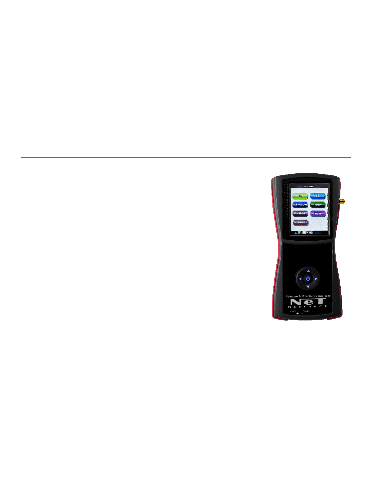
The NETPROBE 2000 is a lightweight, battery-operated test set optimized for monitoring,
testing and troubleshooting Gigabit Ethernet, PDH(E1, E3) , DS1(T1), DS3(T3), Datacom,
CO-DIR, Wi-Fi, VoIP, IPTV, and IEEE C37.94 telecom services. Depending on the actual
configuration ordered, some of these interfaces will not be available in the tester.
This user manual describes the NETPROBE 2000 and provides instruction on how to set it
up and perform tests.
The NETPROBE 2000 test set is menu driven and operated from a touch panel Graphical
User Interface.
Test results are safely accumulated and stored in the nonvolatile memory.
The NETPROBE 2000 is powered by either an external 12VDC adapter or from the
rechargeable long life Lithium Ion Polymer battery. Depending on the number of applied
recharge cycles the battery does not need replacement for several years. Net Research
factory provides instructions how to reinstall the new battery as self service.
Page 17
17
4. DESCRIPTION
4.1 External Interfaces
4.1.1 Top Control Panel
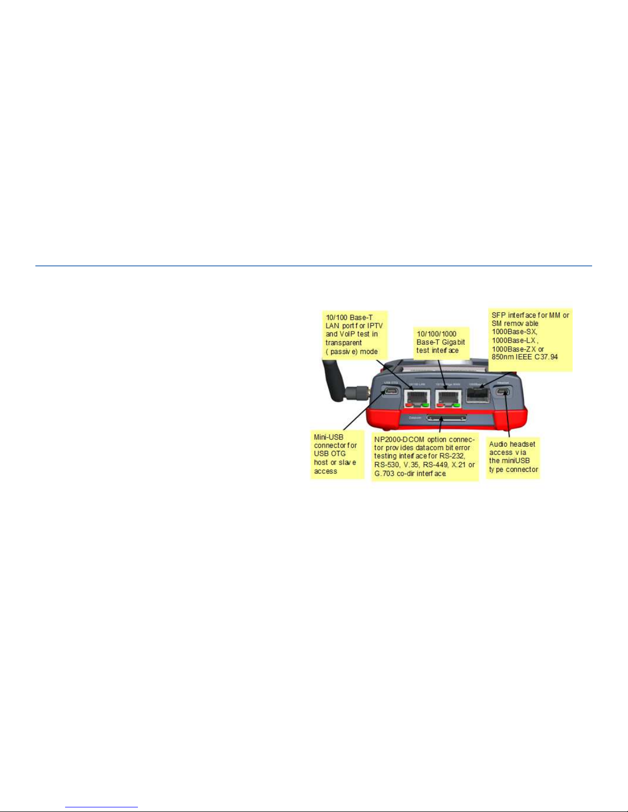
The diagram to the right shows a fully equipped
NetProbe 2000 with optional Gigabit and IEEE
C37.94 ports.
The standard features include the USB port and
Audio micro connector.
The optional datacom connector supports RS-232,
RS-530, RS-449, V-35 and X.21 interfaces with an
adaptor cable. It can also support the optional G.703
Co-dir interface with an adaptor cable.
Both the Datacom (NP2000-DCOM) and G.703 Co-Dir (NP2000-CODIR) options perform Bit Error Test via the DATACOM
connector. This connector acts also as a printer port to a RS-232 thermal printer, model DPU-40.
Page 18
18
4.1.2 Test Interface Signal Panel
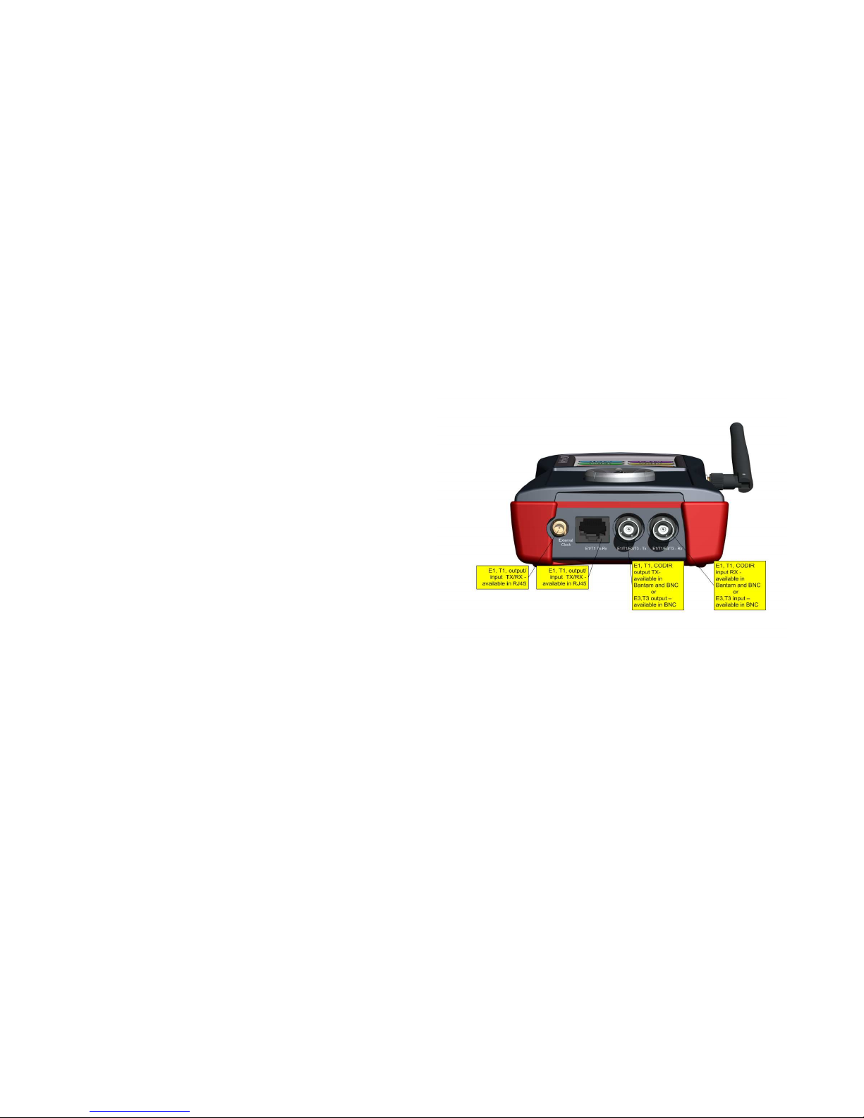
The Signal Panel is used for the PDH (T1, E1, T3, and E3) interface connectors. There are many possible configurations
available to accommodate these interfaces.
The NetProbe image below is configured with a RJ-45
connector for T1/E1 and COAX connectors for T3/E3.
Both RJ-45 (balanced 100/120 Ohm) and BNC (75 Ohm) or
Bantam ( unbalanced 100/120 Ohm) connectors carry
E1/T1 signal or when equipped, the G.703 64kbps Co-Dir.
Also, the E3 and T3 signals are available via the BNC
connectors.
The PDH interfaces along with their line impedance (75 Ohm, 100 Ohm, 120 Ohm) are all user-selectable.
Page 19
19
4.1.3 Front Control Panel
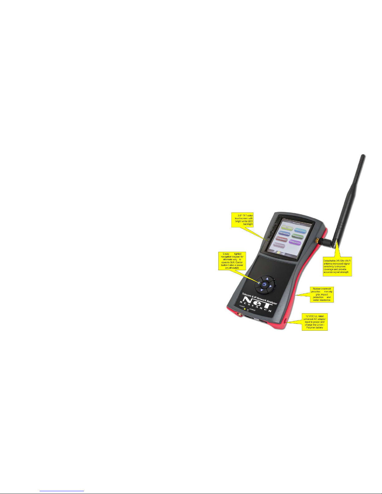
The front Control Panel accommodates a 3.5” LCD touchscreen and
the 5- way navigation switch assembly.
The 4 arrows of navigation switch allow an alternate way to control
the cursor position and the OK button selects the item pointed by
the cursor on the LCD display.
Additionally, the OK button serves as a power ON/OFF button.
Pressing the OK button for at least 2 seconds turns power ON;
pressing it again for 3 seconds opens a menu that allows the user to
turn power OFF. Optional Power OFF is accomplished via the
Toolbar Soft Power button, which shuts down all processes and
powers down the tester.
Alternatively, hardware Power OFF can also be accomplished by
holding down the OK button for 60 seconds.
Page 20
20
4.2 Graphical User Interface (GUI)
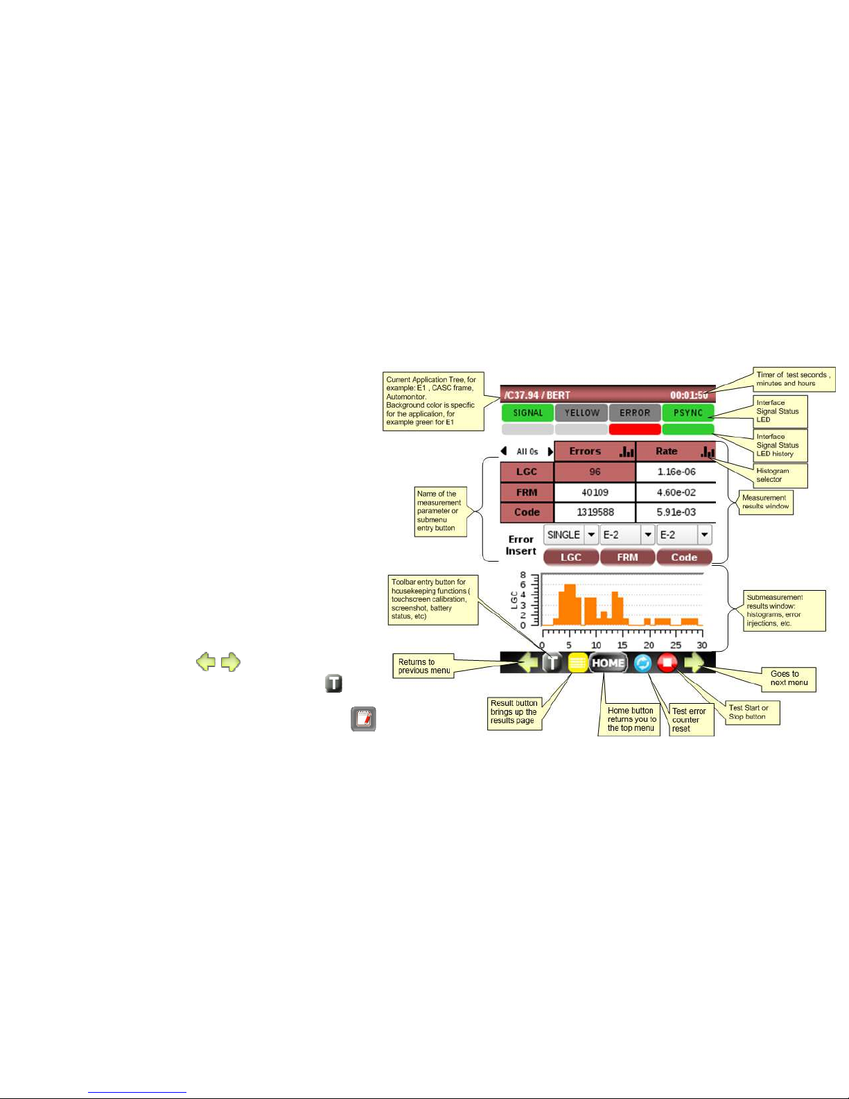
The LCD display is organized into sections:
• Application tree that shows the current
test location in the application
• Signal Status LED’s
• Signal Status history LED’s
• Measurement Results window that may
show the measurement results or a
summary status of the submenu
• Sub measurement results window such as
histogram or error injection menu
• Hot Buttons bar with:
o Go to arrows to previous or next
menu ( )
o Toolbar with housekeeping
functions listed below:
User Profiles and Config
Save/Export functions
Page 21
21
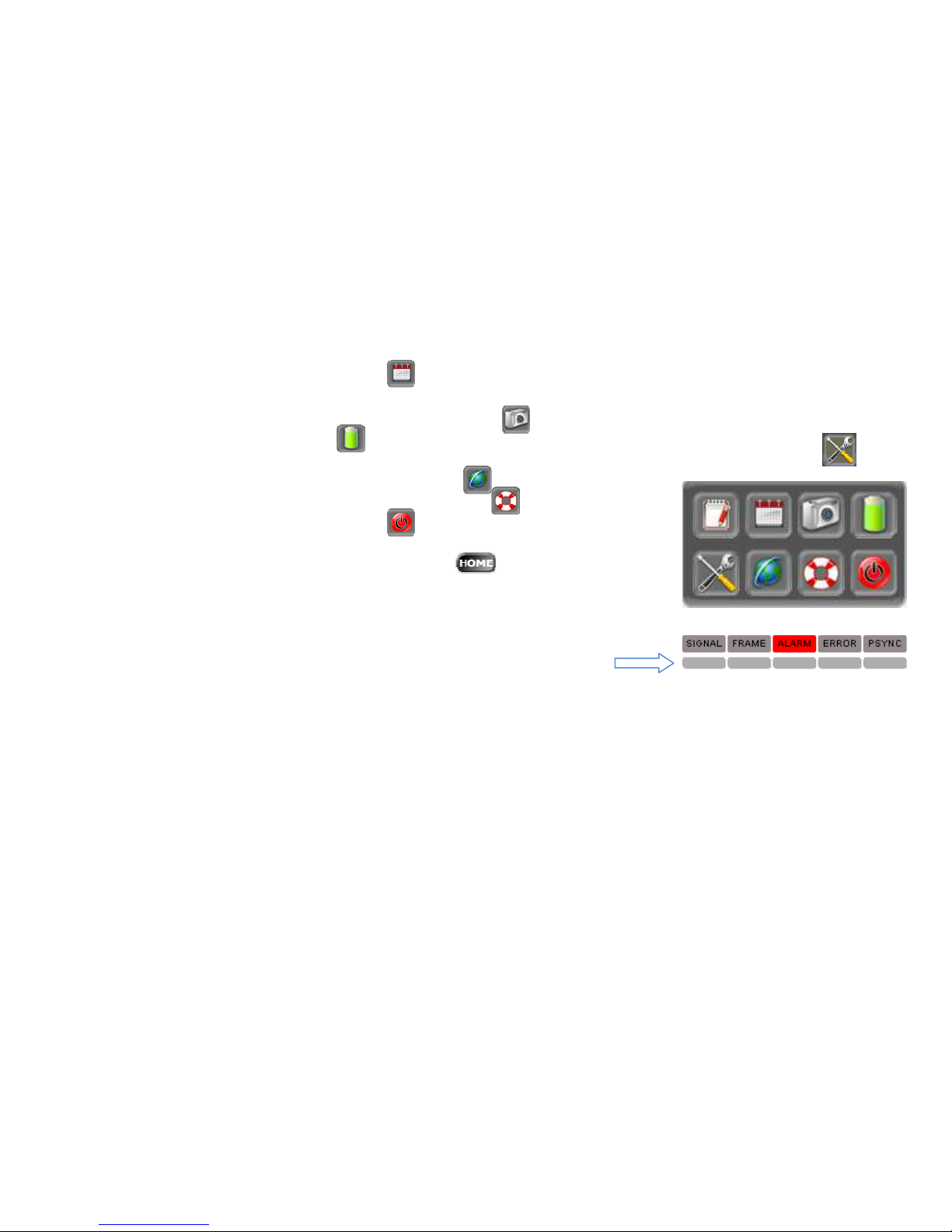
Clock &Calendar setup
Screenshot tool allows taking a screen picture and saving it in a file. This feature is useful when a
temporary event displays on the screen
Battery status
Set Brightness, calibrate the touch screen, erase all tester data and change languages
LAN, WiFi and VNC configurations
Software version info and update tool
Soft Power OFF button
o Result button to enter the test log of saved test results
o HOME button to return to the top menu
o Pause button to pause the screen refresh
o Test Start/Stop button
• Signal and Alarm LED’s and History LED’s
History LED’s can be reset by tapping on any of the five buttons.
Page 22
22
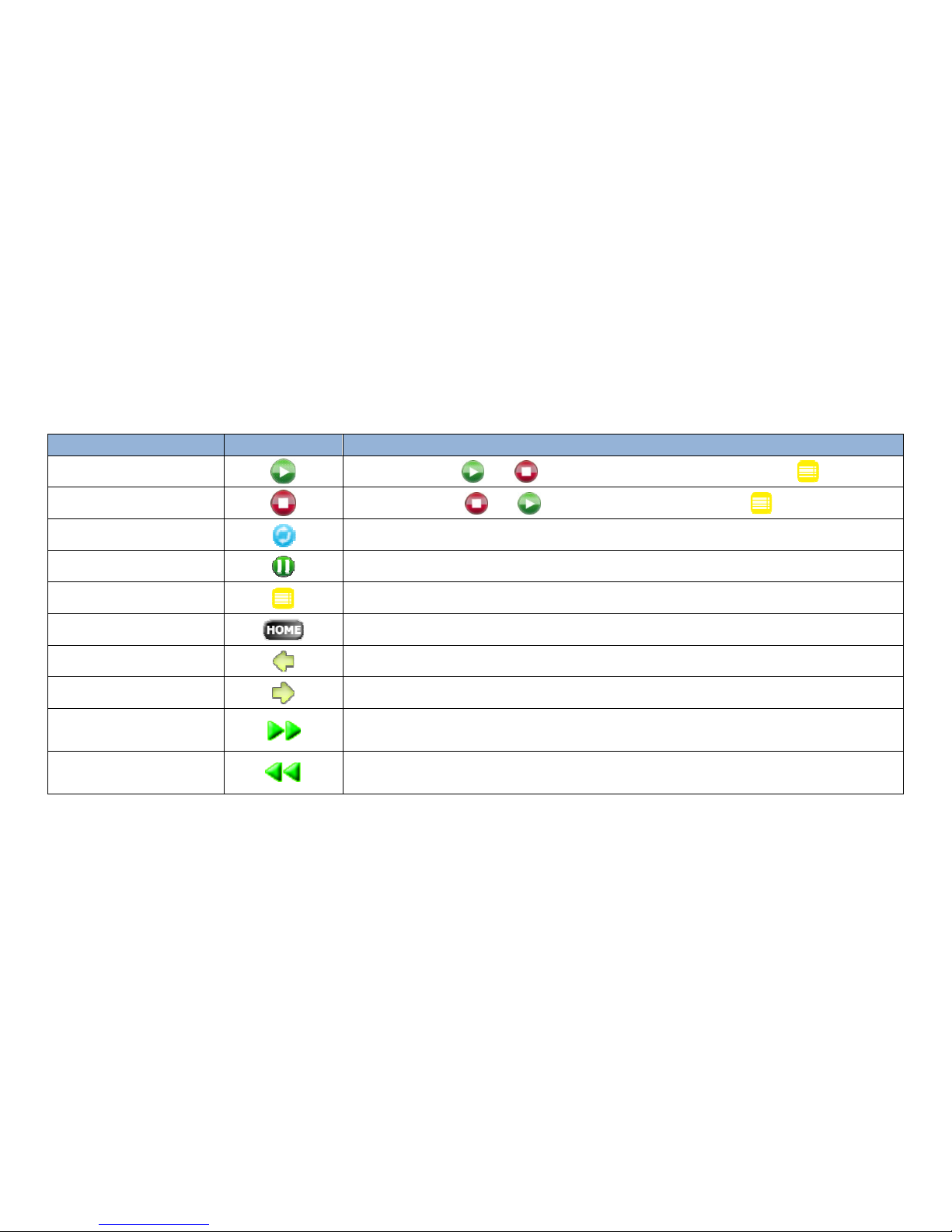
4.3 Operators reference
OPERATOR’S NAME
SYMBOL
DESCRIPTION
START
Toggles between and . Activates test and storing test results in
STOP
Toggles between and . Stops test and storing results in
RESTART
Restarts test and clear current data without stopping transmission
PAUSE
Pauses the current test until pressed again (where available)
TEST RESULT
Enters test log with Results
HOME
If test is not running ( stopped) GUI returns to the main menu
RETURN UP
Returns to the higher level menu
GO TO NEXT MENU
Switched to lower level menu
GO TO ALTERNATE
SUBMENU
Goes to alternate submenu ( used optionally)
RETURN TO
ALTERNATE SUBMENU
Returns to the alternate submenu ( used optionally)
Page 23

23
4.4 Main Menu
Upon Power Up, the display starts with the main menu. Each available application has a
corresponding button and designated color.
Only installed applications are accessible and their buttons active.
Applications that are Not installed, have their buttons greyed out and are inactive.
The E1, T1 and Datacom Interfaces are powered up only when they are activated from
the main menu. This raises the NetProbe’s overall power consumption. Upon return to
the main menu, these interfaces are turned off, reducing the overall power
consumption.
Page 24
24
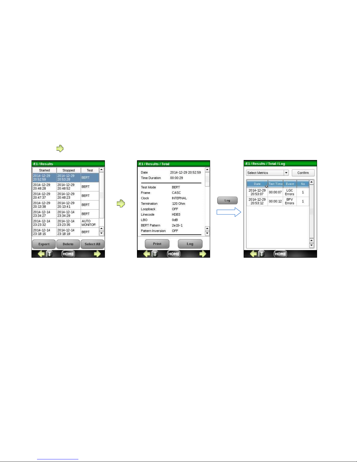
4.4 Test Results
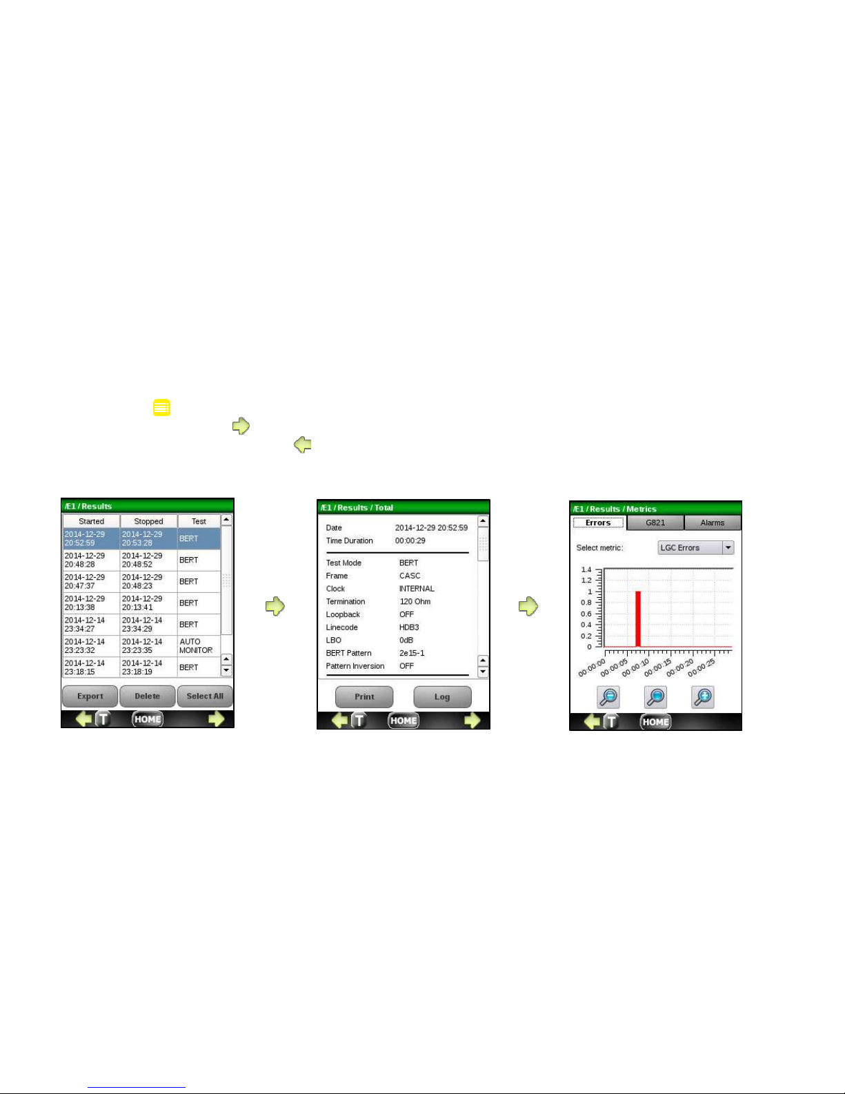
The Test Results menu shows a log of all results for the application currently in use. To view details, highlight the
desired test record and press to display various metric views including histograms. The actual display varies with the
test application that was applied. Press to go back to previous screens.
Page 25
25
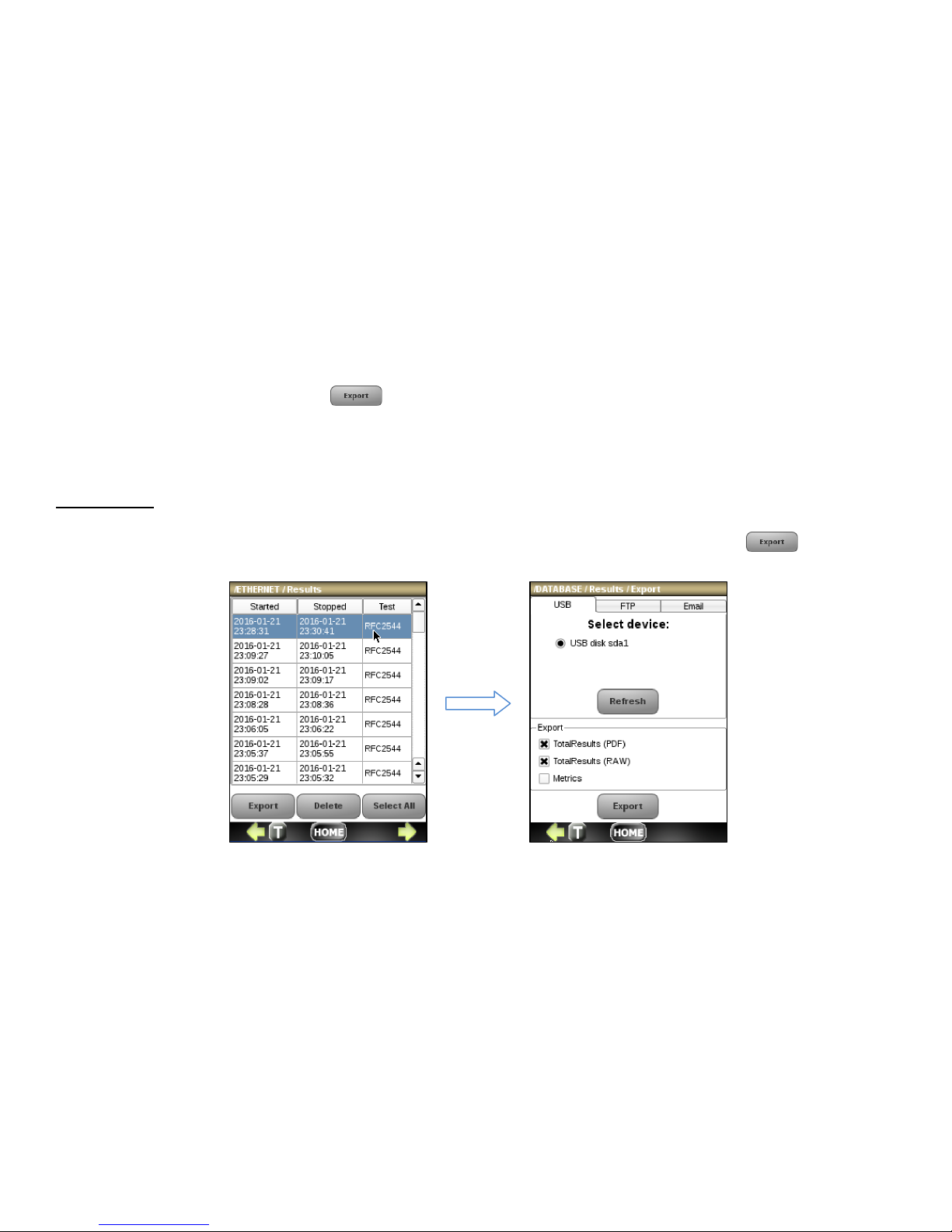
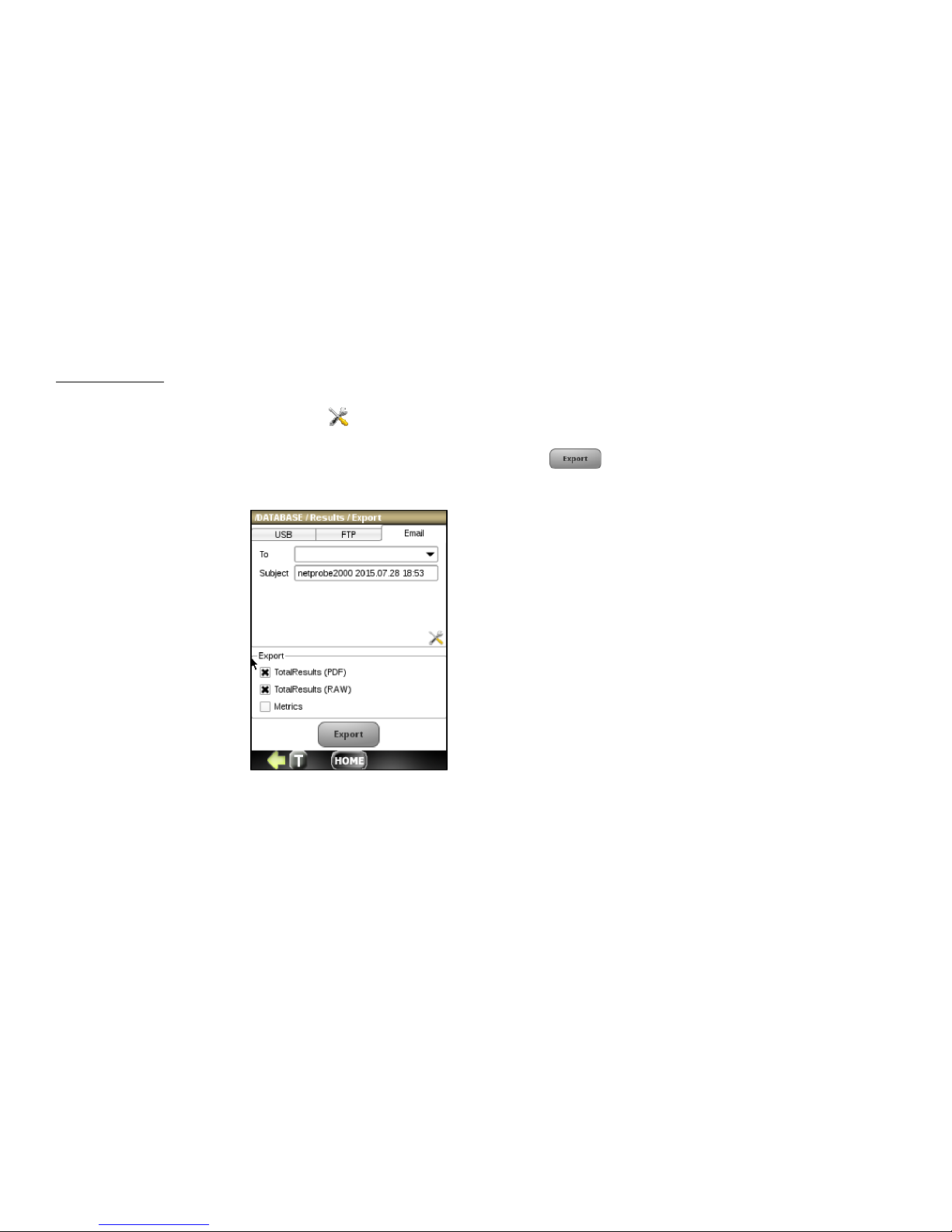
To export the desired test record press from the Test Results screen. Click on the appropriate tab to export by
USB, FTP or email. You can select to export the total results report in PDF or ASCII format by checking the TotalResults
(RAW) and/or TotalResults(PDF) checkboxes. You can also select to export a CSV file for each application metric by
checking the checkbox labeled Metric.
Export by USB
To export to USB, plug the mini-USB adaptor into the NetProbe connector labeled USB at the top of the unit and insert a
USB drive. Click on the USB tab and select a USB drive by clicking on the radio button and press the
button.
Page 26
26
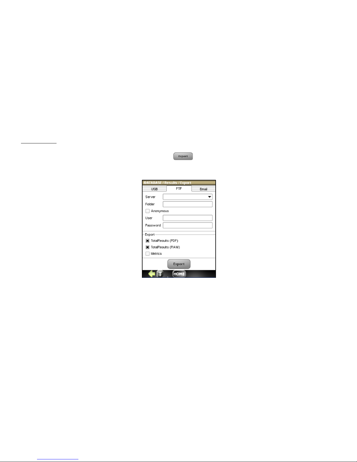
Export by FTP
To export by FTP, connect a CAT5/6 Ethernet cable to the connector labled 10/100 LAN at the top of the unit. Click on
the FTP tab, enter the FTP login information and press the
button.
Page 27
27
Export by Email
To export by FTP, connect a CAT5/6 Ethernet network cable to the connector labeled 10/100 LAN at the top of the unit.
Click on the Email tab then click on the icon to configure your email parameters.
Finish by entering the send-to email address and subject and press the
button,
Page 28
28
To view a log of time-stamps and quantity of Errors and Alarms, choose the record of interest from the Test Results
screen, press and then press the Log button.
Page 29

29
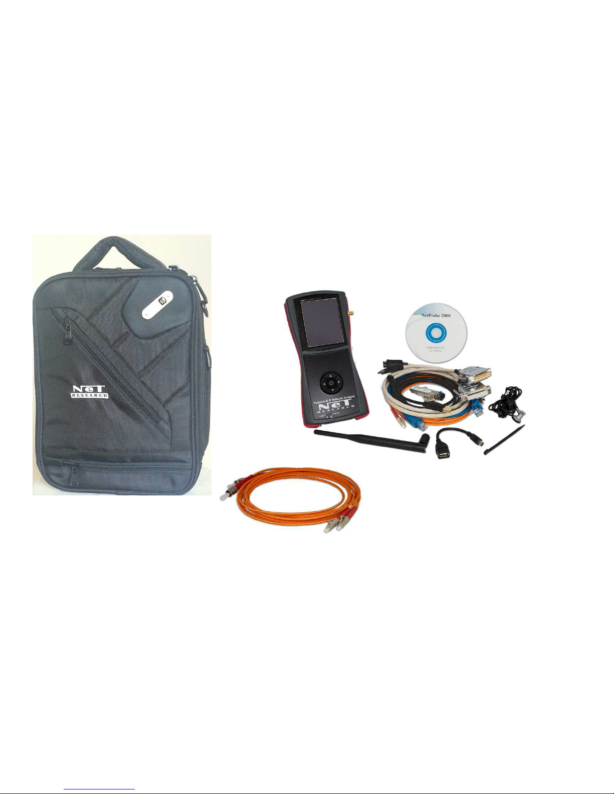
4.5 Standard Accessories
The NetProbe 2000 is provided with the following standard accessories:
• Carrying case with a shoulder strap and a pocket for cables
• Universal AC adapter, 100—240VAC, 12VDC, 1.5A, 50/60Hz, UL, CE, LPS with IEC connector power cord
• USB to mini-USB adapter
• Touchscreen Stylus
• User Manual on CD
4.6 Optional Accessories
Optional accessories include:
• SFP transceivers for C37.94 and Gigabit Ethernet options
• Fiber optic patch cord, duplex LC-ST for C37.94 option
• CAT-6 Ethernet cable for Gigabit Ethernet option
• Datacom DTE and DCE cables for : RS-232, RS-530,RS-449, V.35, X.21
• Miniature mono headset for VoIP, T1 and E1 options
• WiFi 2/5Ghz antenna for Wifi Option
Note: Contact Net Research or
your local representative for
the current list of available
options.
Page 30
30
Page 31
31
5. E1 ANALYZER OPTION
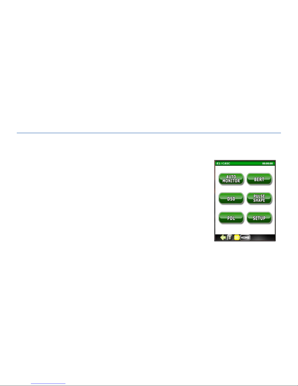
5.1 Top Menu
The E1 Analyzer option starts up with the top menu shown to the right with buttons for
the following test functions:
AUTO MONITOR
BERT
DSO
PULSE SHAPE (analysis)
PDL (propagation delay test)
SETUP
Page 32
32
5.2 Set Up
Use the Setup menu to configure the E1 transmitter and receiver parameters listed under the General tab. This menu
also allows you to define the Auto Monitor thresholds used to determine pass/fail results under the Automonitor tab .
5.2.1 General Configuration Tab
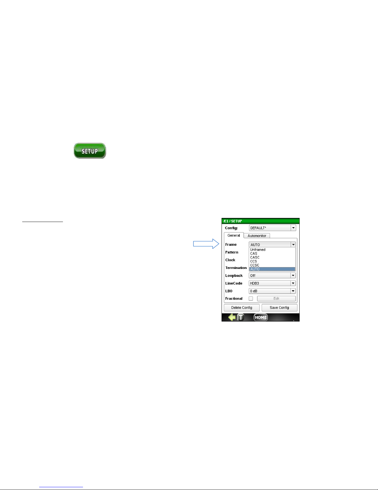
E1 Frame Type
• Unframed – all bits used for data
• CAS- Channel Associated Signaling
• CAS- Channel Associated Signaling with Signaling
• Common Channel Signaling (ISDN)
• Common Channel Signaling with CRC
• Auto – detect E1 signal, line code, frame type and BERT type
• (if any) automatically
Page 33
33
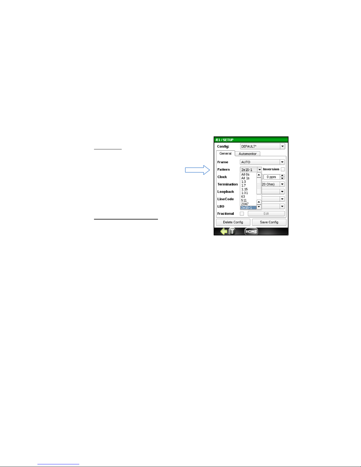
E1
Pattern
OFF, 63, 511, 2047, 2-15-1, 221-1, 2-23-1, QRSS, All 0’s, All
1’s, 1:3, 1:7, 1:15, 1:31. The
pattern can also be
configured in Setup.
Test Length (
not shown)
Unlimited, 30 s, 1 min, 5 min,
10 min, 30 min, 1hr, 3 hr. 6 hr,
12 hr, 1 day, 2 days, 3 days,
user-defined.
Page 34
34
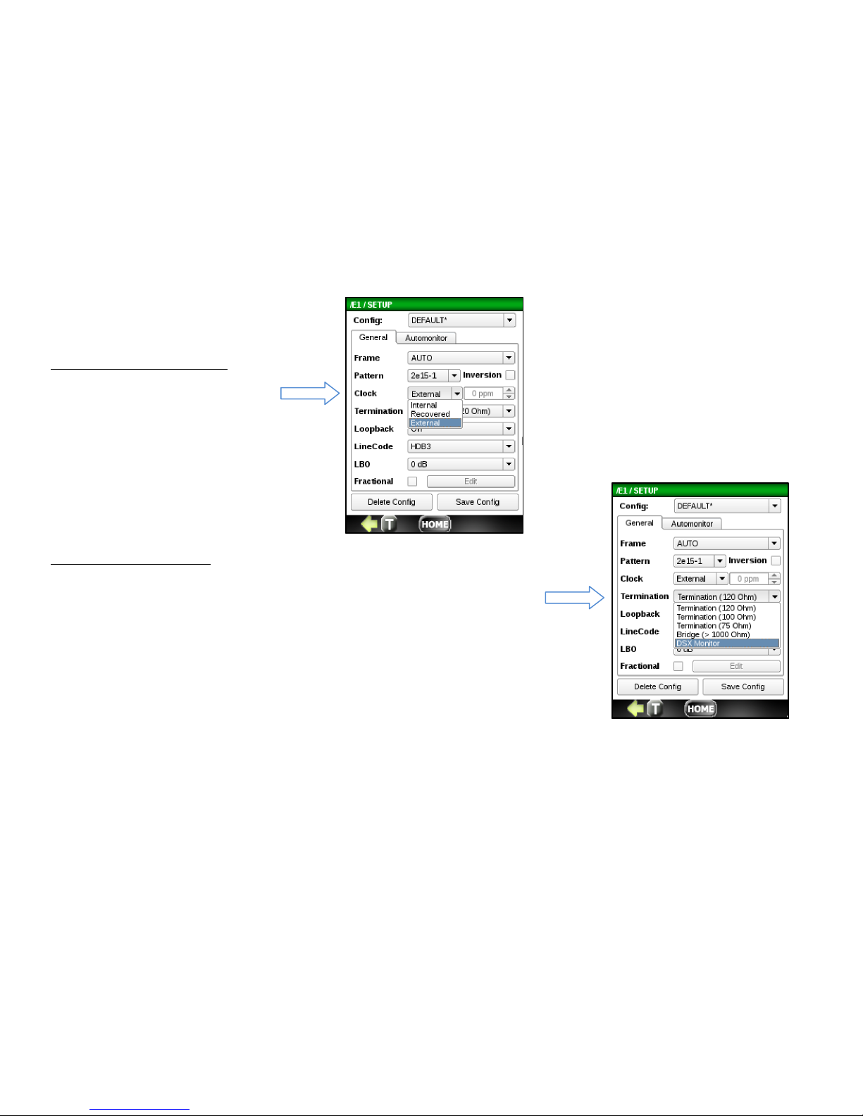
E1 Transmitter Clock Source
• Internal - from TCXO 3ppm
• Recovered - from Receive Data Rx
• External – from 0-5V TTL clock source
E1 Line Termination Type
• Termination - 120 Ohm, 100 Ohm, 75 Ohm, Tx and Rx software switchable
• Bridge – Input Rx impedance > 1kOhm, intended for monitoring E1 line on
• the outside plant circuit.
• DSX Monitor – 120/100 0r 75 Ohm termination on DSX test point. Typically
• provides 20 dB of attenuation across a 100 Ohm resistive load.
Page 35
35
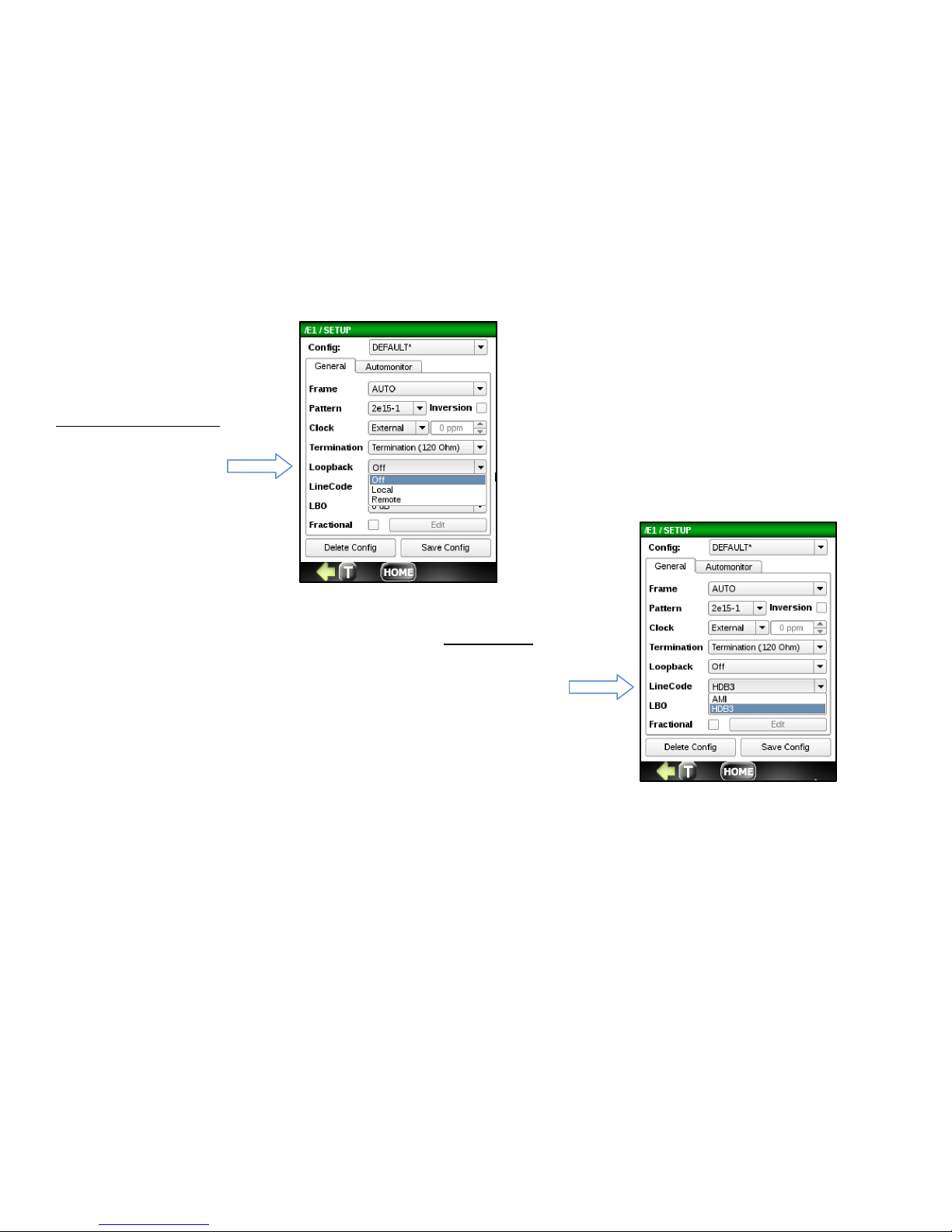
E1 Line Loopback mode
• Local loop
• Remote Loop
E1 Li
n
e Code
• AMI Code
• HDB3 code
Page 36
36
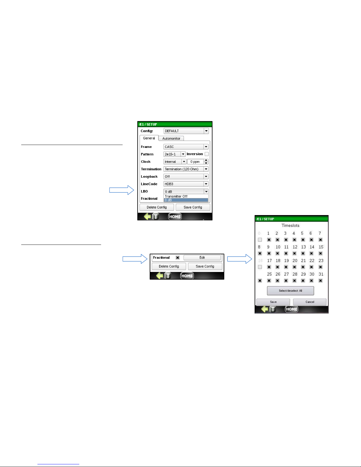
E1 Line Build Out Transmitter TX(LBO)
E1 Transmitter at 0 dB level or OFF
E1 Fractional Submenu Enable
To setup Fractional testing, click on
the checkbox labeled Fraction and press
the Edit button. Next, select desired
Timeslots for nx64kbps fractional E1
testing (where n =1 …15,17..31 for
CAS and n = 1…31 for CCS framing).
Page 37
37
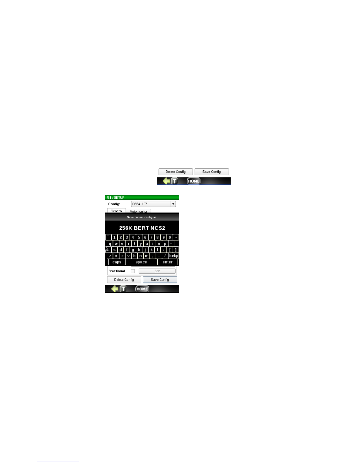
Saving the SETUP
The buttons labeled Delete Config and Save Config allow you to delete and save any configuration file currently shown in
the Config window. If the config is not saved, it will retain the last config used.
To save a config, press the Save Config button.
You can save as Default or you
can enter a new name for the
current configuration. To save,
press the enter button.
When you return the Setup
menu, you will see any new
configs created in the Config
drop down.
Page 38
38
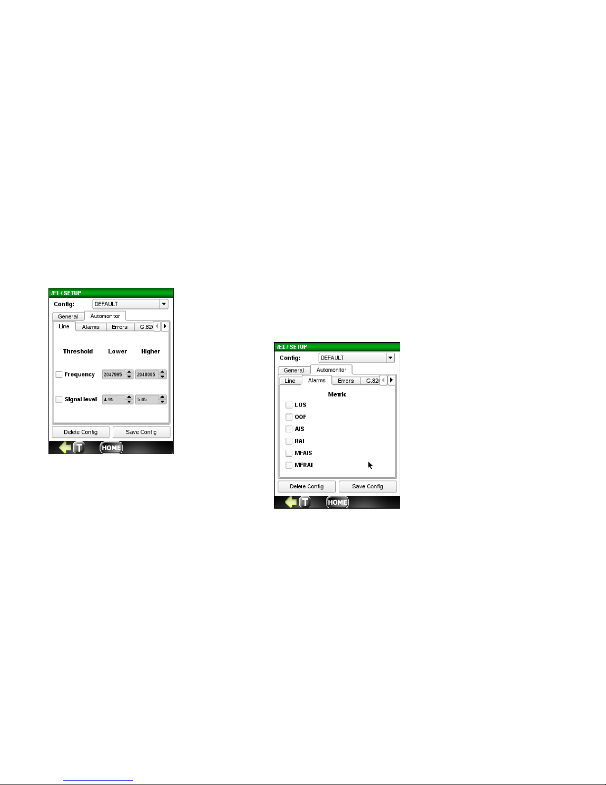
5.2.2 Automonitor Configuration Tab
Line Tab (Enable and Set Thresholds)
• Frequency (Hz)
• Signal Level (V)
A
larm Tab (Enable)
• LOS (Loss of Sync)
• OOF (Out of Frame)
• AIS (All 1’s Alarm Indicator Signal)
• RAI (Remote Alarm Indicator)
• Multi-frame AIS
• MFRAI (Multi-frame RAI)
Page 39
39
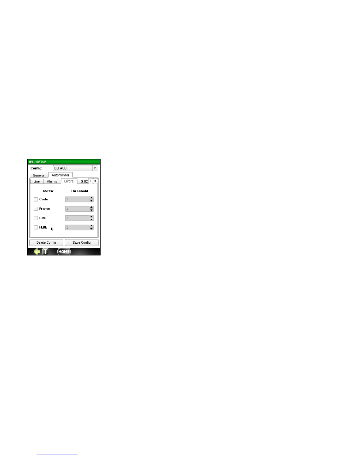
Errors Tab (Enable and Set Thresholds)
• Code
• Frame
• CRC
• FEBE
Page 40
40
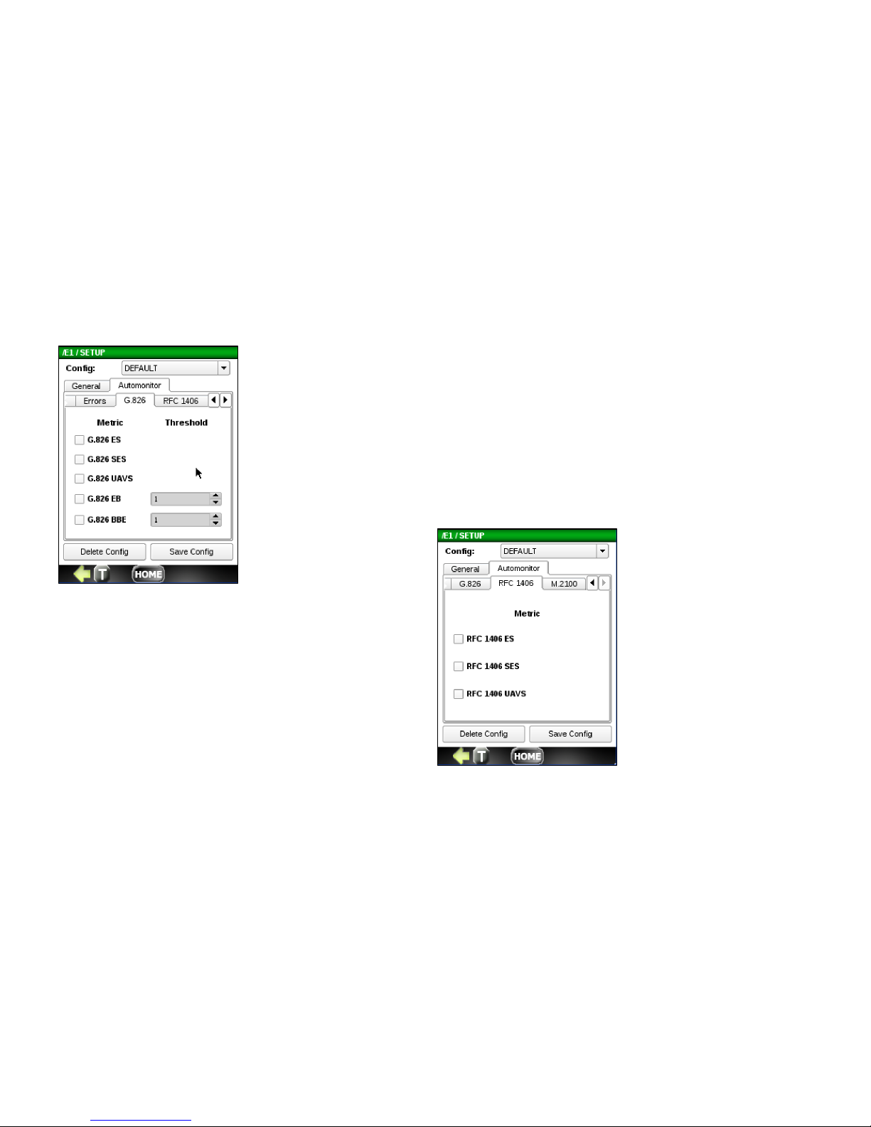
RFC1406 Tab (Enable)
• ES (Errored Seconds)
• SES (Severed ES)
• UAVS (Unavailable Seconds)
G.826 Tab (Enable)
• ES (Errored Seconds)
• SES (Severe ES)
• UAVS (Unavailable Seconds)
G.826 Tab (Enable and Set Thresholds)
• EB (Errored Block)
• BBE (Background Block Error)
Page 41
41
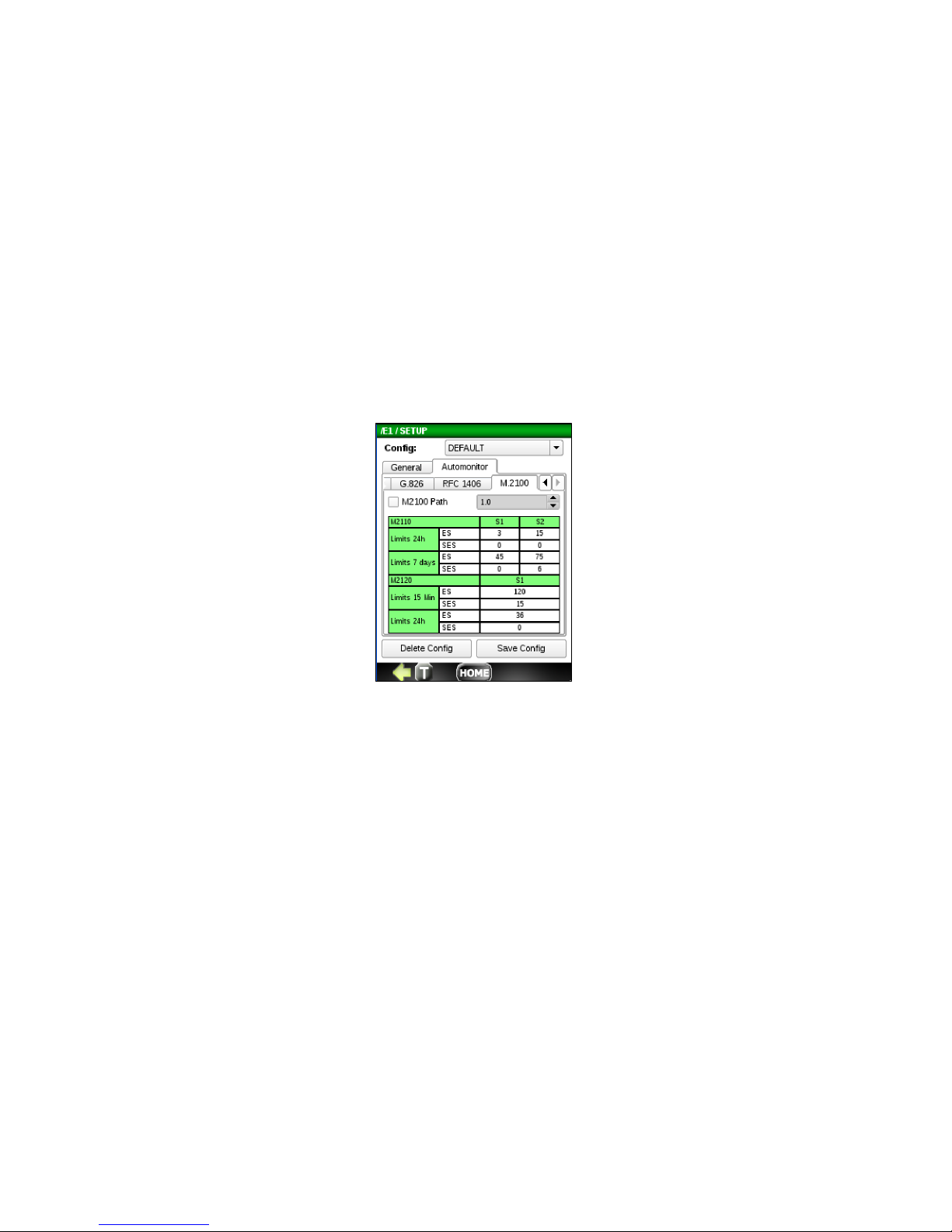
M.2110 S1 an
d S2 Thresholds
• ES (Errored Seconds)
• SES (Severed ES)
M2120 S1 Thresholds
• ES (Errored Seconds)
• SES (Severed ES)
M.2100 Tab (Enab
le and Set Path Value)
This M.2100 Path Allocation value has a range
from 0.5% to 63.5%, in 0.5% increments. Based
on this value, the S1 and S2 limits of the M.2110
and M.2120 are preset accordingly. Set this
M.2100 Path value as required.
Page 42
42
Saving the SETUP
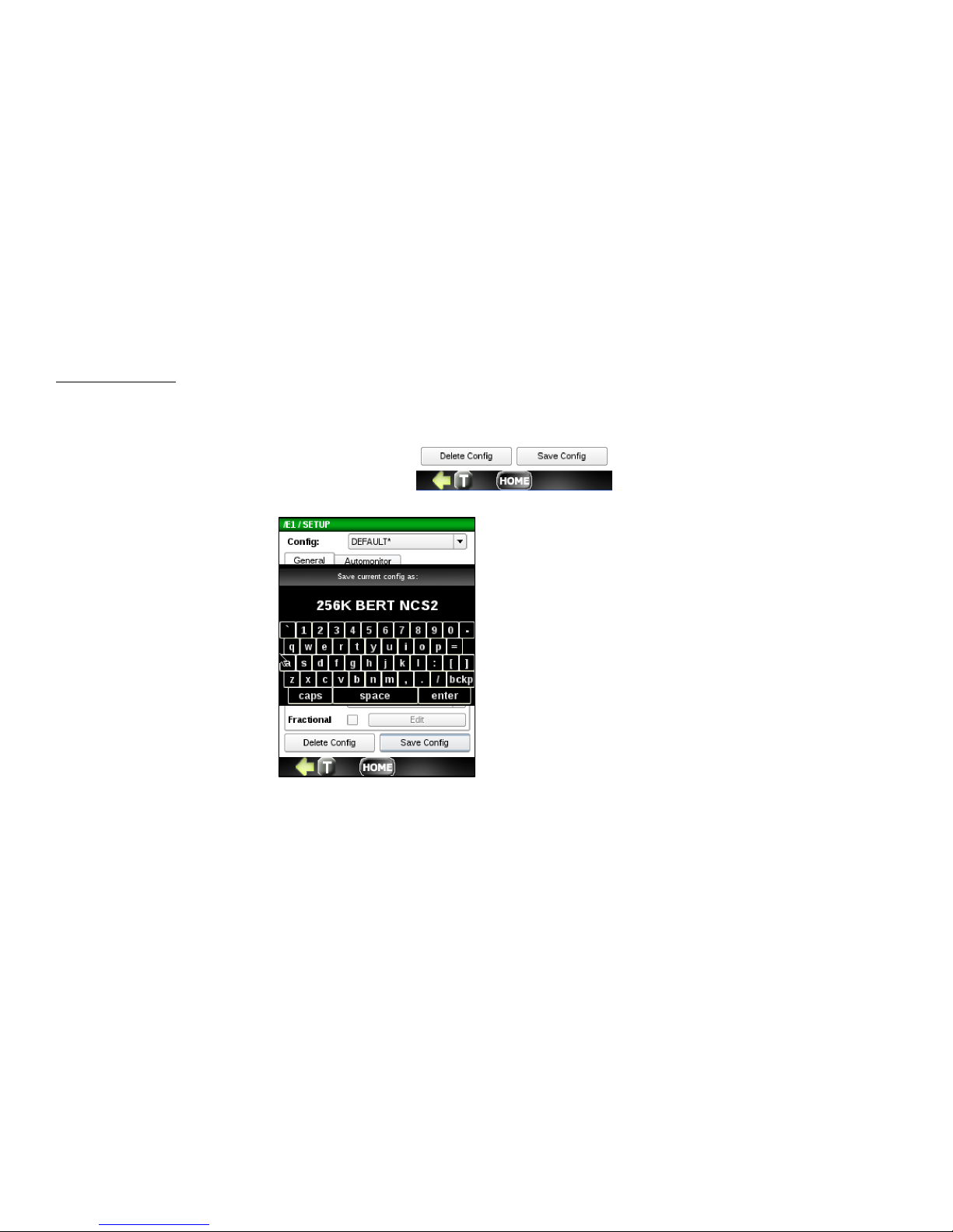
The buttons labeled Delete Config and Save Config allow you to delete and save any configuration file currently shown in
the Config window. If the config is not saved, it will retain the last config used.
To save a config, press the Save Config button.
You can save as Default or you
can enter a new name for the
current configuration. To save,
press the enter button.
When you return the Setup
menu, you will see any new
configs created in the Config
drop down.
Page 43
43
5.3 Auto Monitor
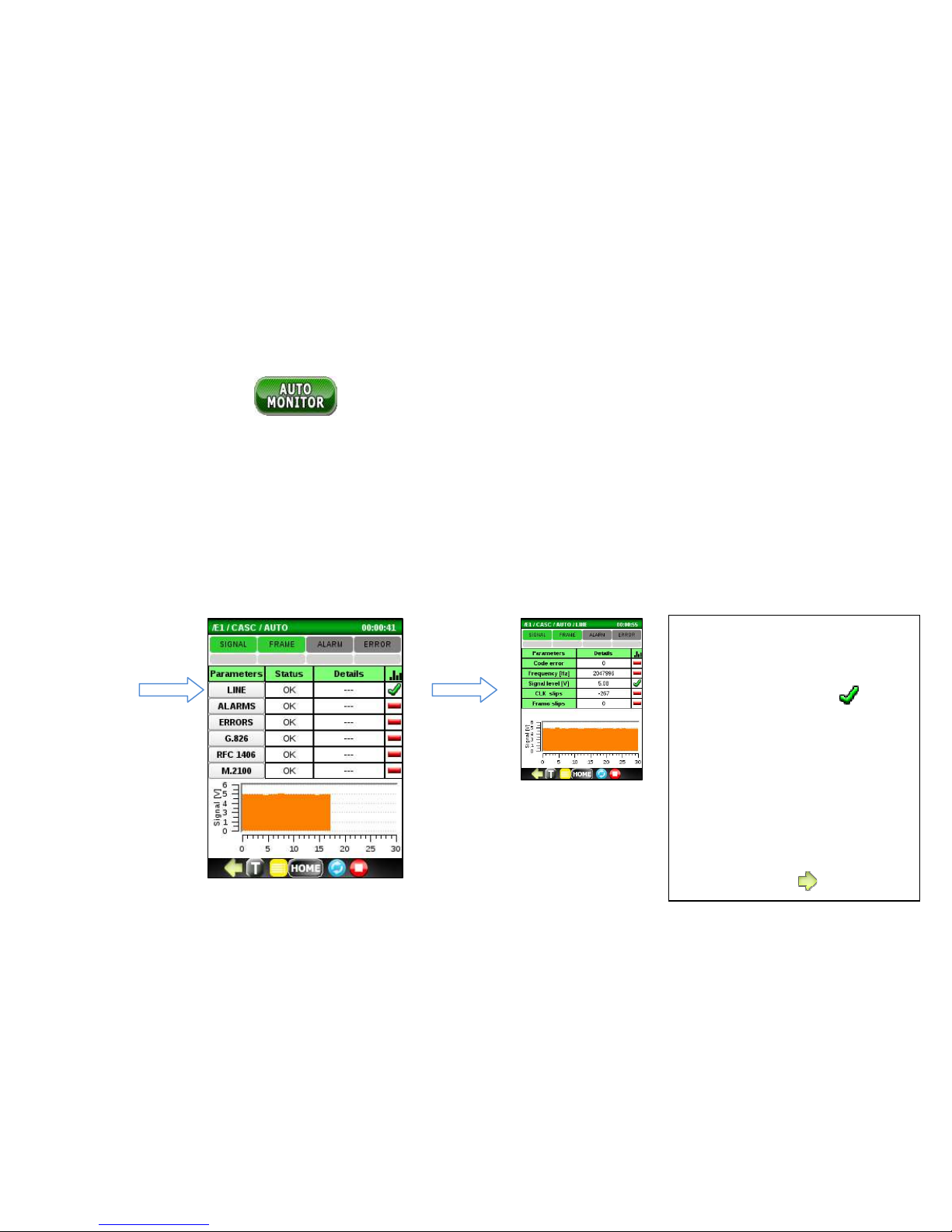
Run the AUTO MONITOR application to automatically check the tested E1 signal for the following Parameter categories:
Line Errors, Alarms, Errors, G.826 analysis, RFC1406 analysis and M.2100 analysis. For each, the status is displayed along
with failure details. The indicators at the top display the current and historical state of SIGNAL/FRAME/ALARM/ERROR
events.
You can display additional sub-detail metrics for each category by clicking on a Parameter category name button. For
instance, click on the Line button to display detail metrics for Code errors, Frequency and more. See example below.
Tips:
Click in the histogram column to
display a histogram for the
corresponding metric.
Click a box under
SIGNAL/FRAME/ALARM/ERROR
to reset the history of that
event.
Green arrows at the bottom
may be used to display
additional information for a
metric category.
Page 44
44
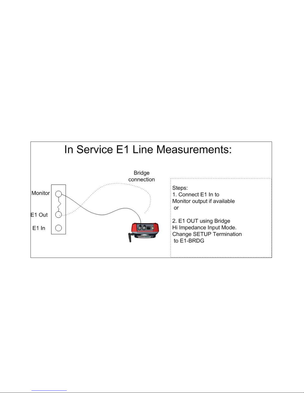
To run the Auto Monitor test, connect the NetProbe 2000 E1 receiver to either a DSX MON jack or E1OUT for BRIDGE if
DSX MON jack is not available. Connect the E1 signal to the appropriate connector (RJ-45, COAX, Bantam) on the
NetProbe. The transmitter Tx is disabled by default.
Page 45
45
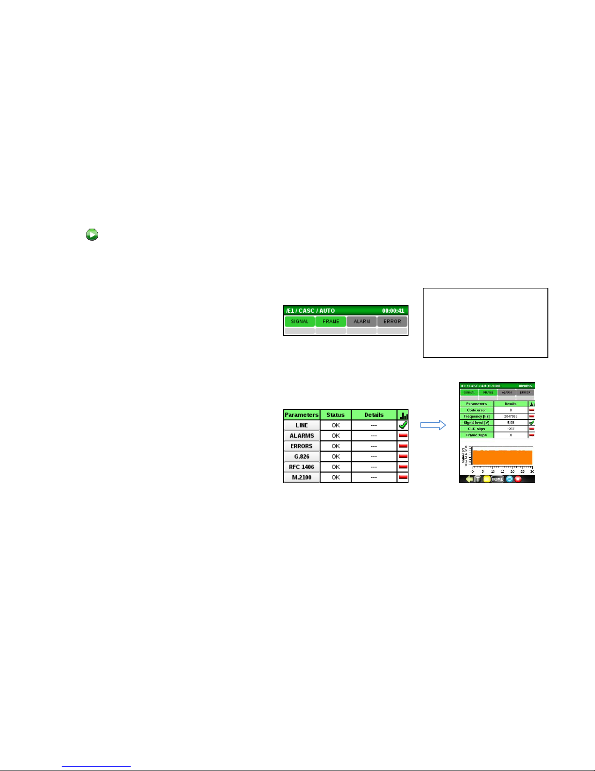
Next, press button to start the AUTO MONITOR test.
Check the AUTO MON main screen and observe the following:
• The real-time SIGNAL and FRAME (with
Framed data) indicators at the top of the
screen are Green. Red indicates a problem.
If these indicators are red, check all circuit
connections and E1 setup
• The history indicators below are gray. Red
indicates a problem. If an event
(SIGNAL/FRAME/ALARM/ERRROR) occurs,
the corresponding gray history area will
remain red until it is reset.
• STATUS boxes report OK. If not, check under
DETAILS, if available, or click on a Parameter
category name to display sub-detail metrics.
The OK/Fail thresholds are configured under
the Setup Automonitor tabs.
Tip:
Click on a history indicator
box or a Status box to reset
the corresponding event or
status.
Page 46
46
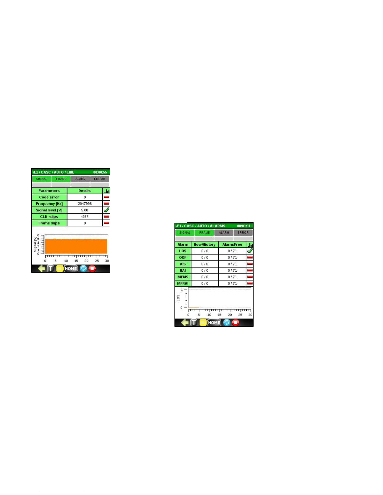
Each category and its sub-detail metrics are described below.
Line measurements
• Code Errors
• Frequency
• Signal Level
• Clock Slips
• Frame Slips
Alarms
• LOS (Loss of Sync)
• OOF (Out of Frame)
• AIS (All 1’s Alarm Indicator Signal)
• RAI (Remote Alarm Indicator)
• Multi-frame AIS
• MFRAI (Multi-frame RAI)
Page 47
47
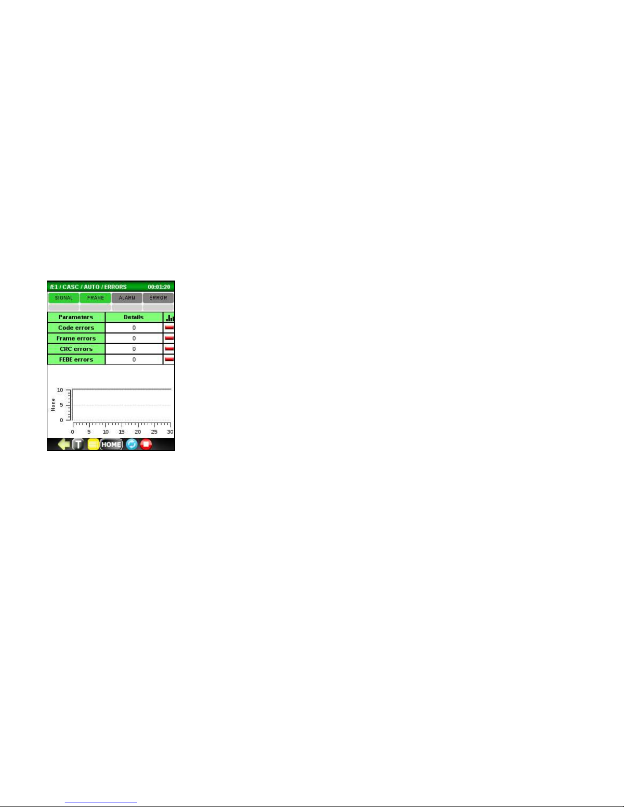
Errors
• Code
• Frame
• CRC
•
FEBE
Page 48
48
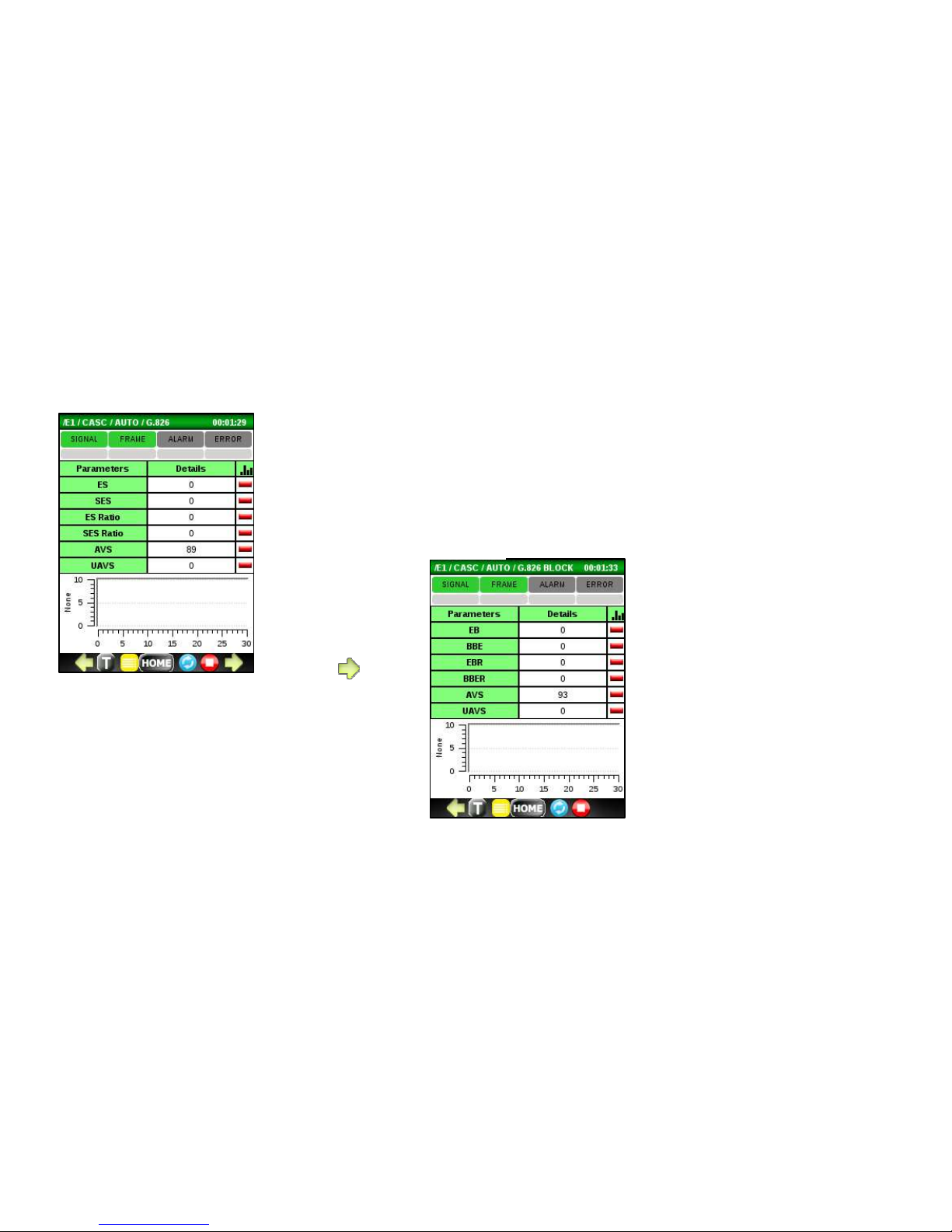
G.826
• ES (Errored Seconds)
• SES (Severe ES)
• ES Ratio %
• SES Ratio %
• AVS (Available Seconds)
G.826
Block
• EB (Errored Block)
• BBE (Background Block
Error)
• EBR (EB Ratio %)
• BBER BBE Ratio %)
• AVS (Available Seconds)
•
UAVS (Unavailable Seconds)
Page 49
49
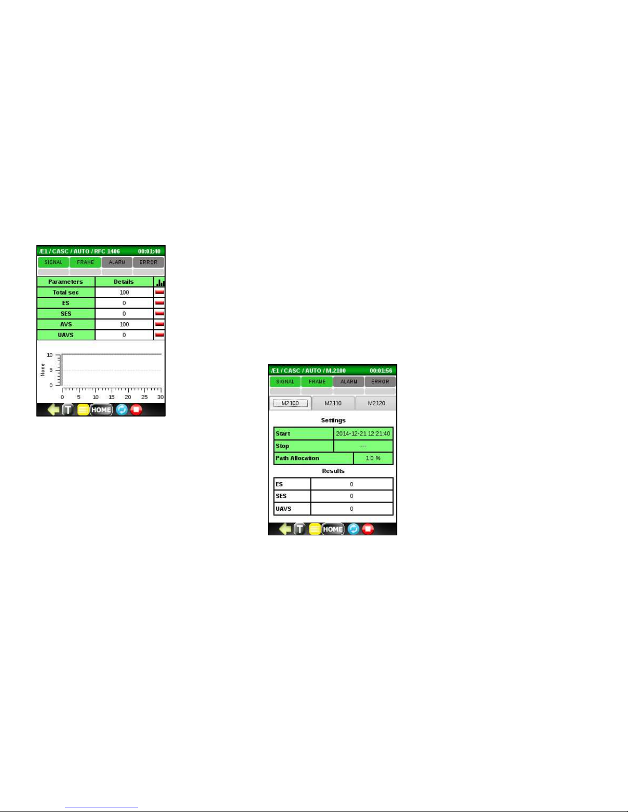
RFC1406
• Total Seconds
• ES (Errored Seconds)
• SES (Severed ES)
• AVS (Available Seconds)
• UAVS (Unavailable Seconds)
M.2100 Tab
• ES (Errored Seconds)
• SES (Severed ES)
• UAVS (Unavailable Seconds)
Page 50
50
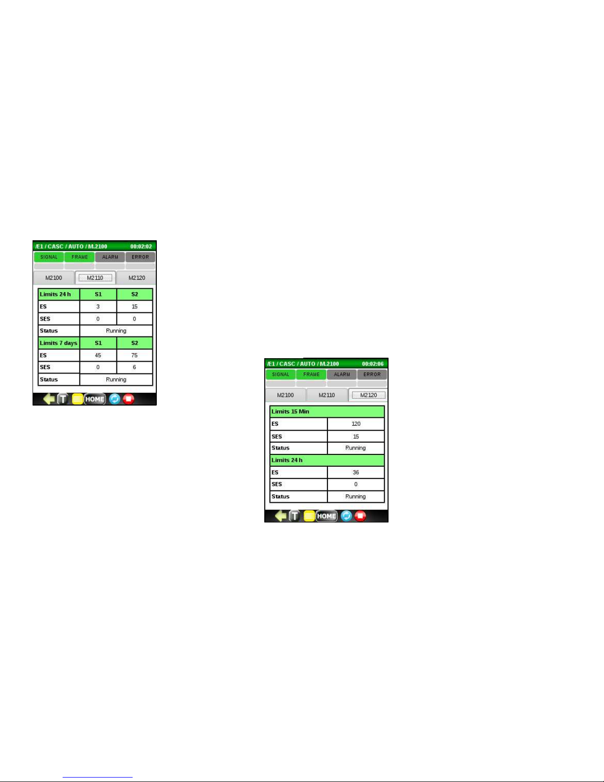
M.2110 Tab
Limit 24 Hours
• ES (Errored Seconds)
• SES (Severed ES)
• Status
Limit 7 days
• ES (Errored Seconds)
• SES (Severed ES)
•
Status
M.2120
Tab
:
Limit 15 Minutes
• ES (Errored Seconds)
• SES (Severed ES)
• Status
Limit 24Hours
• ES (Errored Seconds)
• SES (Severed ES)
• Status
Page 51
51
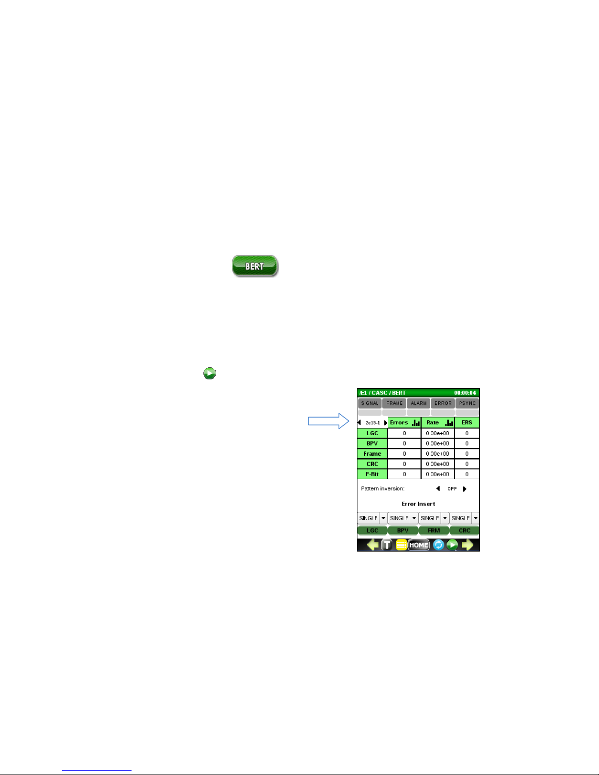
5.4 Bit Error Testing (BERT)
Run the BERT application to check the integrity of an E1 circuit. It can be run with a loopback or end to end with another
test set. The indicators at the top display the current and historical state of SIGNAL/FRAME/ALARM/ERROR/PSYNC
events. The test results are reported as errors or error rates. Any events, including Alarms and G.821 metrics, are also
reported.
Before you start transmitting with the button, you can easily select a test pattern. In the example below, a test
pattern of 2e15-1 is selected with no inversion.
A de
fault BERT test pattern is 2
-15-
1. Other patterns can
be selected from the list by scrolling left or right. Choices
include OFF, 63, 511, 2047, 2-15-1, 2-21-1, 2-23-1, QRSS,
All 0’s, All 1’s, 1:3, 1:7, 1:15, 1:31. The pattern can also be
configured in Setup.
Page 52
52
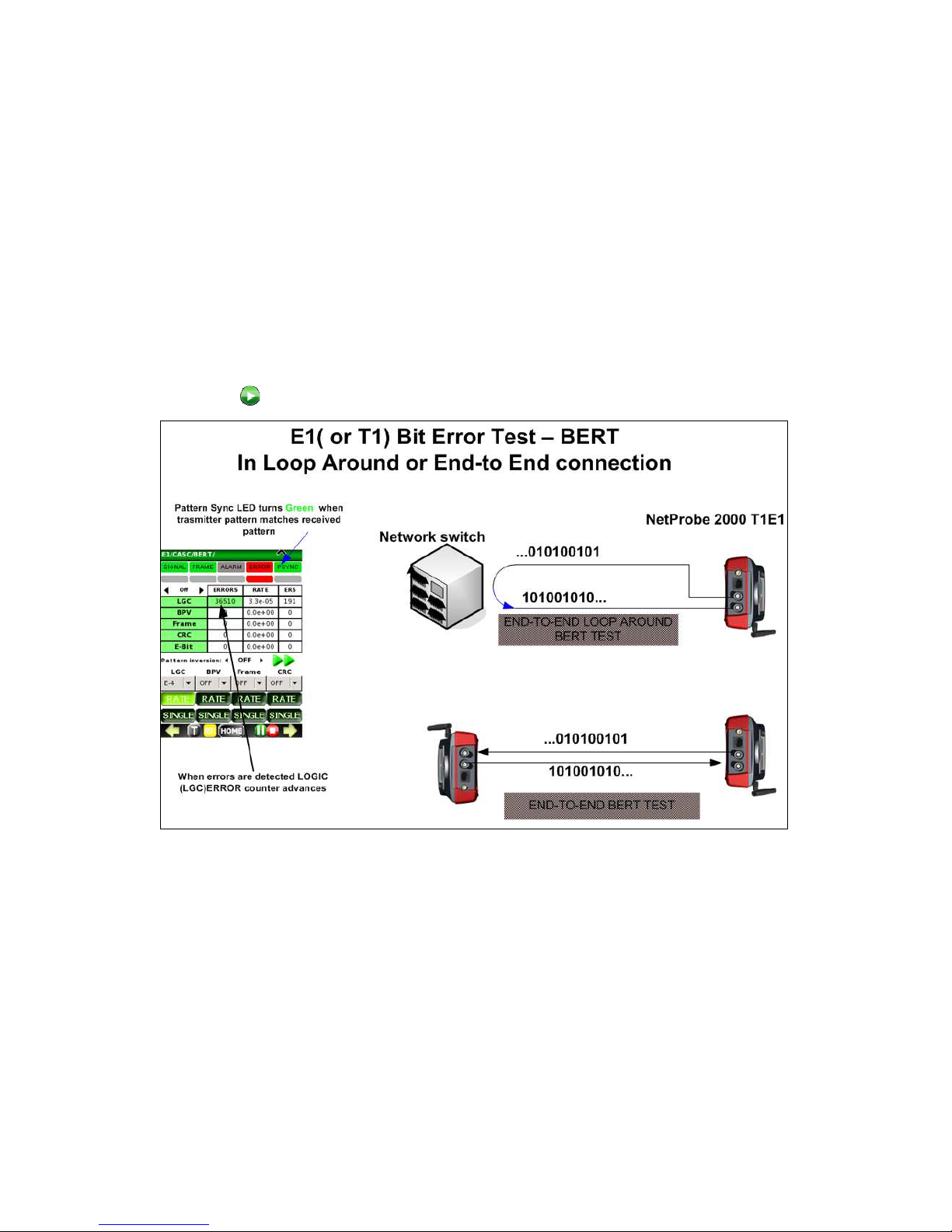
A typical loop around or point-to-point Bit Error Test setup is shown below. After the bantam, BNC or RJ-45 cable
connection is made, press to start the BERT test.
Page 53
53
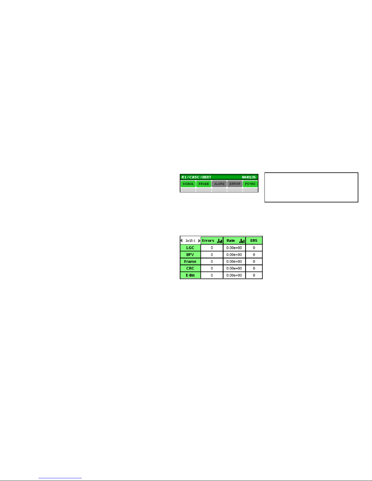
Check the BERT main screen and observe the following:
• The real-time SIGNAL, PSYNC and FRAME
(with Framed data) indicators at the top of
the screen are Green. Red indicates a
problem. If these indicators are red, should
check all circuit connections and E1 setup.
• The history indicators below are gray. Red
indicates a problem. If an event
(SIGNAL/FRAME/ALARM/ERRROR/PSYNC)
occurs, the corresponding gray history area
will remain red until it is reset.
• Error counters report 0 or at least are not
quickly incrementing. If these are quickly
incrementing, check all circuit connections
and E1 setup.
Tip:
Click on any history indicator box
to reset all history indicators.
Page 54

54
Optionally, a const
ant bit error rate can be injected using the RATE menu.
Select a rate from the pull down menu and press the corresponding
green button to begin the error RATE injection.
Tip:
Click in the Errors or Rate
columns to display a histogram
for the corresponding metric.
Click on the thin gray bar to
hide it.
Green arrows at the bottom
can be used to display
additional metrics, alarms and
timeslot information.
Tip:
To verify that everything
is setup properly after
starting BERT, click on
the LGC button to force
and detect a single bit
error.
Page 55
55
5.4.1 ALARM menu
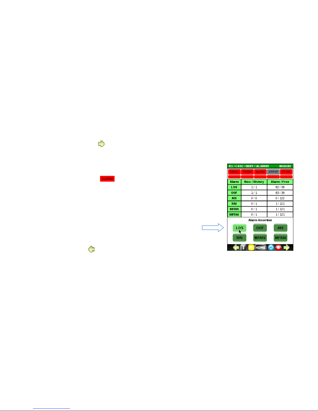
To access the Alarms menu, press from the main BERT screen.
Use this menu to:
• Monitor the current and history alarm status to determine which
alarms caused the LED to turn red.
• Force an alarm condition onto the E1 line by pressing an Alarm
Insertion button. Caution: The alarm insertion will be continuous until
pressed again.
o LOS (Loss of Signal)
o OOF (Out of Frame)
o AIS (All 1’s Alarm Indicator Signal)
o RAI (Remote Alarm Indicator)
o MFAIS (Multi-frame All 1’s Indicator)
o MFRAI (Multi-frame RAI)
• To exit, press .
Page 56
56
5.4.2 G.821 ERROR menu
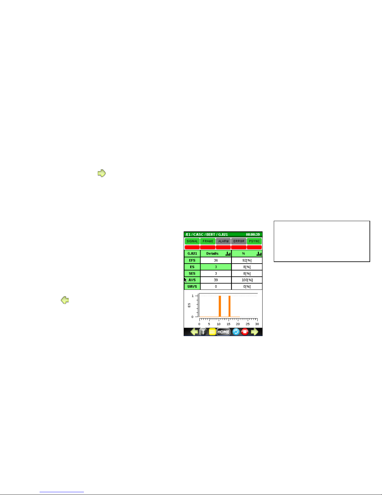
To access this menu, press from the ALARM menu.
Use this menu to:
• Monitor the current and history ERROR
status to determine the severity of the
errors that generated an ERROR indication.
• Monitor G.821 counters and percentages.
o EFS (Error Free Seconds)
o ES (Errored Seconds)
o SES (Severe ES)
o AVS (Available Seconds)
o UAVS (Unavailable Seconds)
• Display a histogram
To exit, press .
Tip:
Click in the Details or %
columns to display a histogram
for the corresponding metric.
Page 57
57
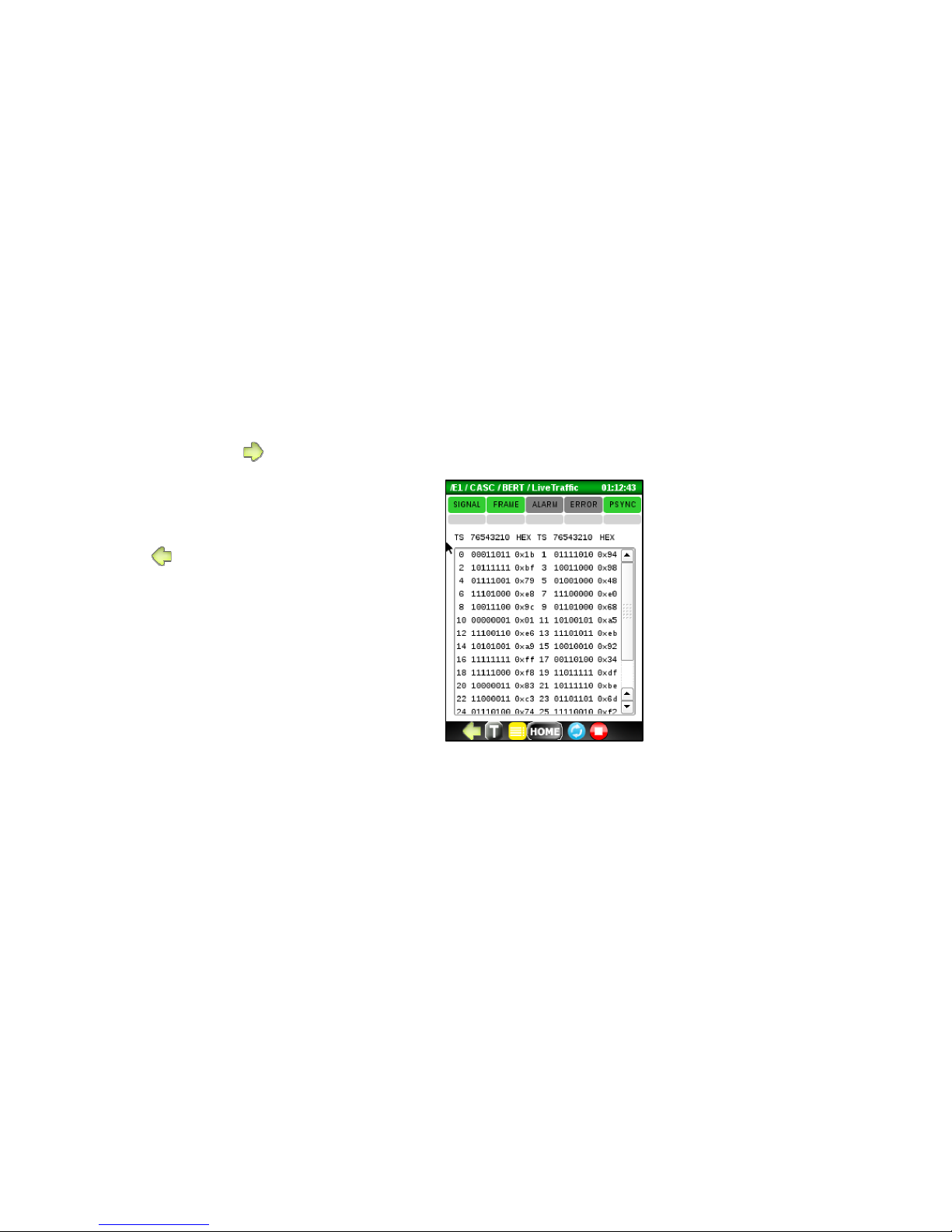
5.4.3 Live Traffic menu
To access this menu, press from the G.821 ERROR menu.
Use this menu to view the binary and hexadecimal
value in each timeslot.
To exit, press .
Page 58
58
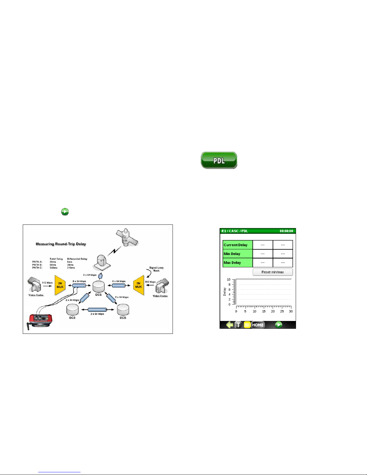
5.5 Propagation Delay Measurement (PDL)
Run the Propagation Delay Measurement application to measure the round trip loopback delay around the E1 circuit
heck the integrity of an E1 circuit.
A typical loop around connection for measuring PDL is shown below. After the bantam, BNC or RJ-45 cable connection
is made, press to start the PDL measurement.
Page 59
59
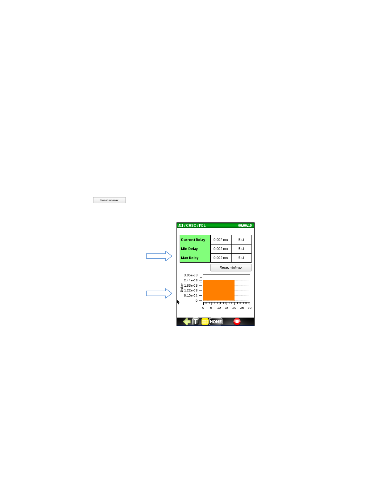
When the PDL measurement begins, the tester will first reset the displayed results and then calibrate. After a couple
seconds, the Current Delay, Minimum Delay and Maximum Delay values will display along with a histogram.
The Current Delay, Minimum Delay and Maximum Delay is measured and reported in milli-seconds (ms) and unit
intervals (ui’s). Press the button to reset the Min Delay and Max Delay values.
Page 60
60
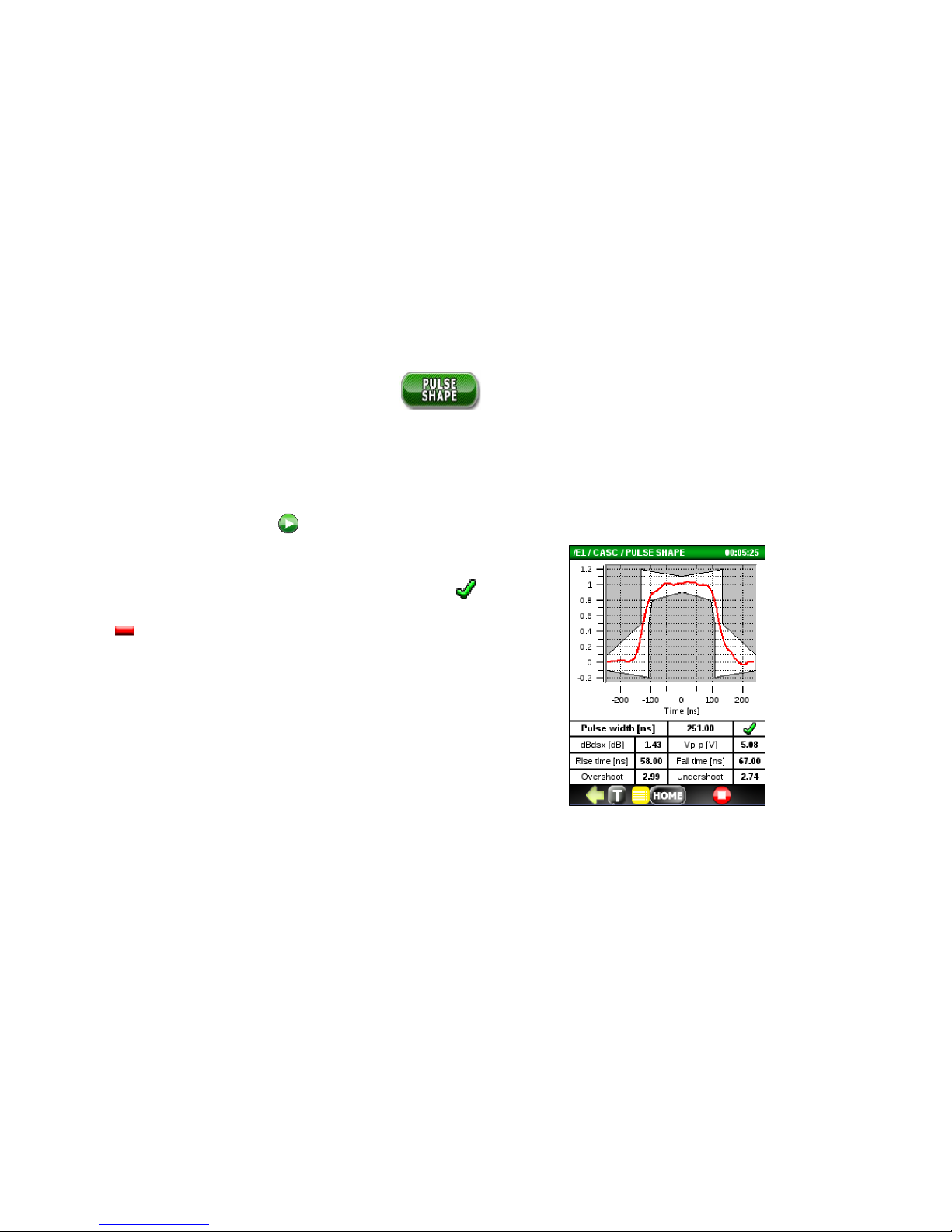
5.6 Pulse Shape Analysis (PSA)
Run the Pulse Shape Analysis (PSA) application to check if the E1 pulse shape complies with ITU-T G.703 specifications.
To plot and analyze the E1 pulse shape, first connect the E1 signal to be tested and select the appropriate Termination
from the E1 Setup menu. Press to start the PSA test.
If the pulse can be normalized it will plot inside the G.703 template. If
the pulse fits 100% inside the template, the test PASSED ( ). If any
part of the plot of the plot falls outside of the template, the test
FAILED ( ).
Page 61
61
5.6 DS0 Testing
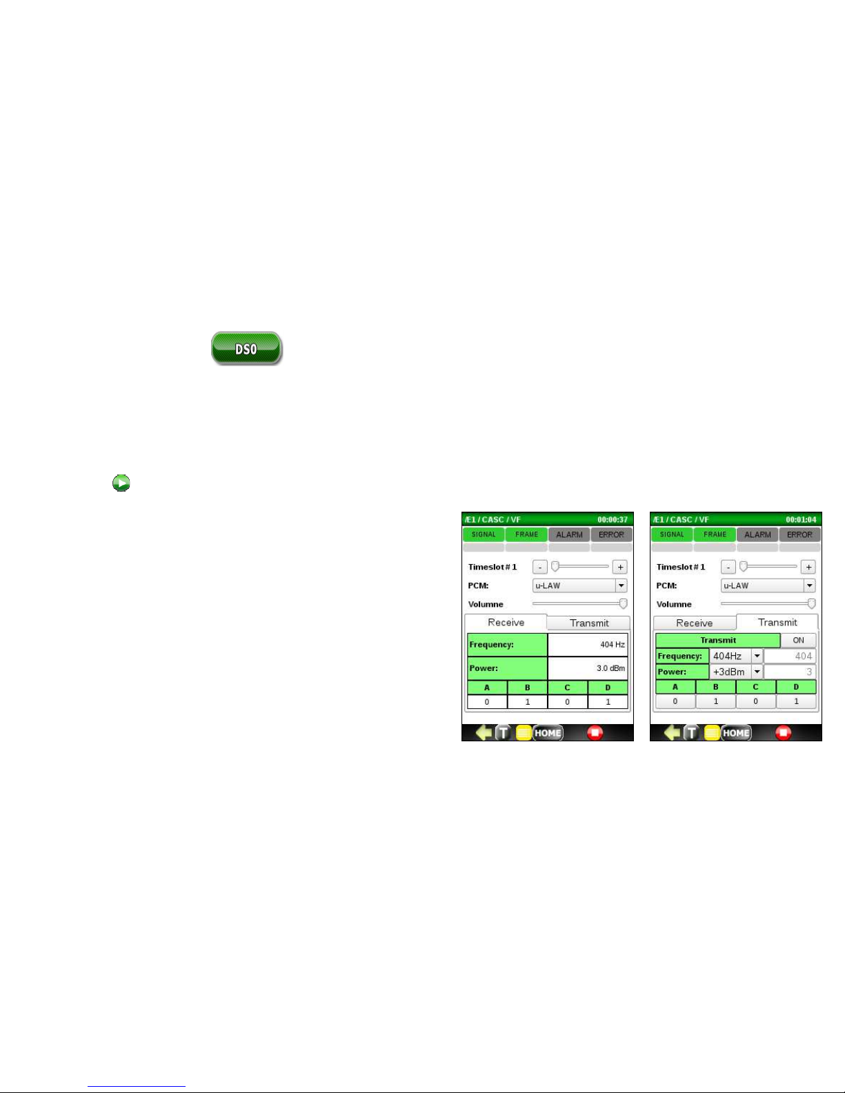
Run the DSO Testing application to measure the frequency and power of any received tones and monitor the ABCD bits
of a DSO sub channel. The application also allows you to listen to the audio in a timeslot using the supplied headset.
To run a DSO test, connect the E1 signal to be tested, select a timeslot number, select PCM Companding (u-Law/A-Law)
and press to start a DSO test.
DS0 testing includes:
• Listening to any of the 30 DS0 Voice Channels using the
supplied headset.
• Measuring the frequency of the received signal. Test
tones are typically 404Hz, 1004Hz, and 1804Hz.
• Measuring the power (dBm) of the received test tones.
If the reading is not available, N/A will display.
• Reading the ABCD bits for the selected timeslot.
• Transmitting signal 300-3404Hz, -40.0-3.0dBm.
• Configuring ABCD bits for the selected timeslot.
Page 62
62
6. T1 ANALYZER OPTION
6.1 Top Menu
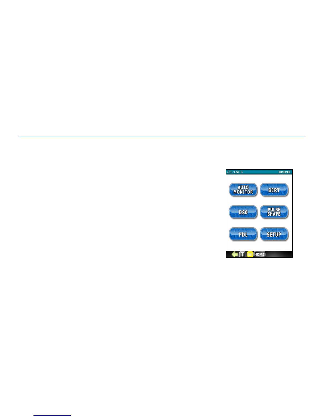
The T1 analyzer option starts up with the top menu shown to the right with buttons
for the following test functions:
AUTO MONITOR
BERT
DSO
PULSE SHAPE (analysis)
PDL (propagation delay test)
SETUP
Page 63
63
6.2 Set Up
Use the Setup menu to configure the T1 transmitter and receiver parameters listed under the General configuration tab.
This menu also allows you to define the Auto Monitor thresholds used to determine pass/fail results under the
Automonitor tab .
6.2.1 General Configuration Tab
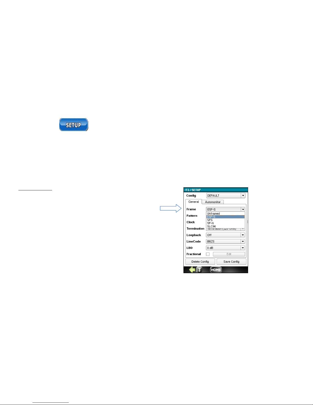
T1 Frame Type
• Unframed – all bits used for data
• ESF-S Extender Super Frame
• SFS
• SF-N
Page 64
64
T1
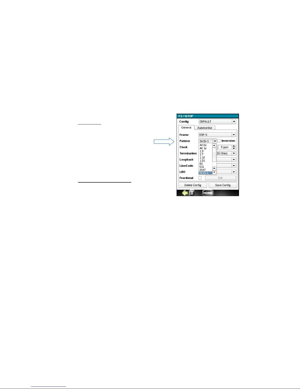
Pattern
OFF, 63, 511, 2047, 2-15-1, 221-1, 2-23-1, QRSS, All 0’s, All
1’s, 1:3, 1:7, 1:15, 1:31. The
pattern can also be
configured in Setup.
Test Length (not shown)
Unlimited, 30 s, 1 min, 5 min,
10 min, 30 min, 1hr, 3 hr. 6 hr,
12 hr, 1 day, 2 days, 3 days,
user-defined.
Page 65
65
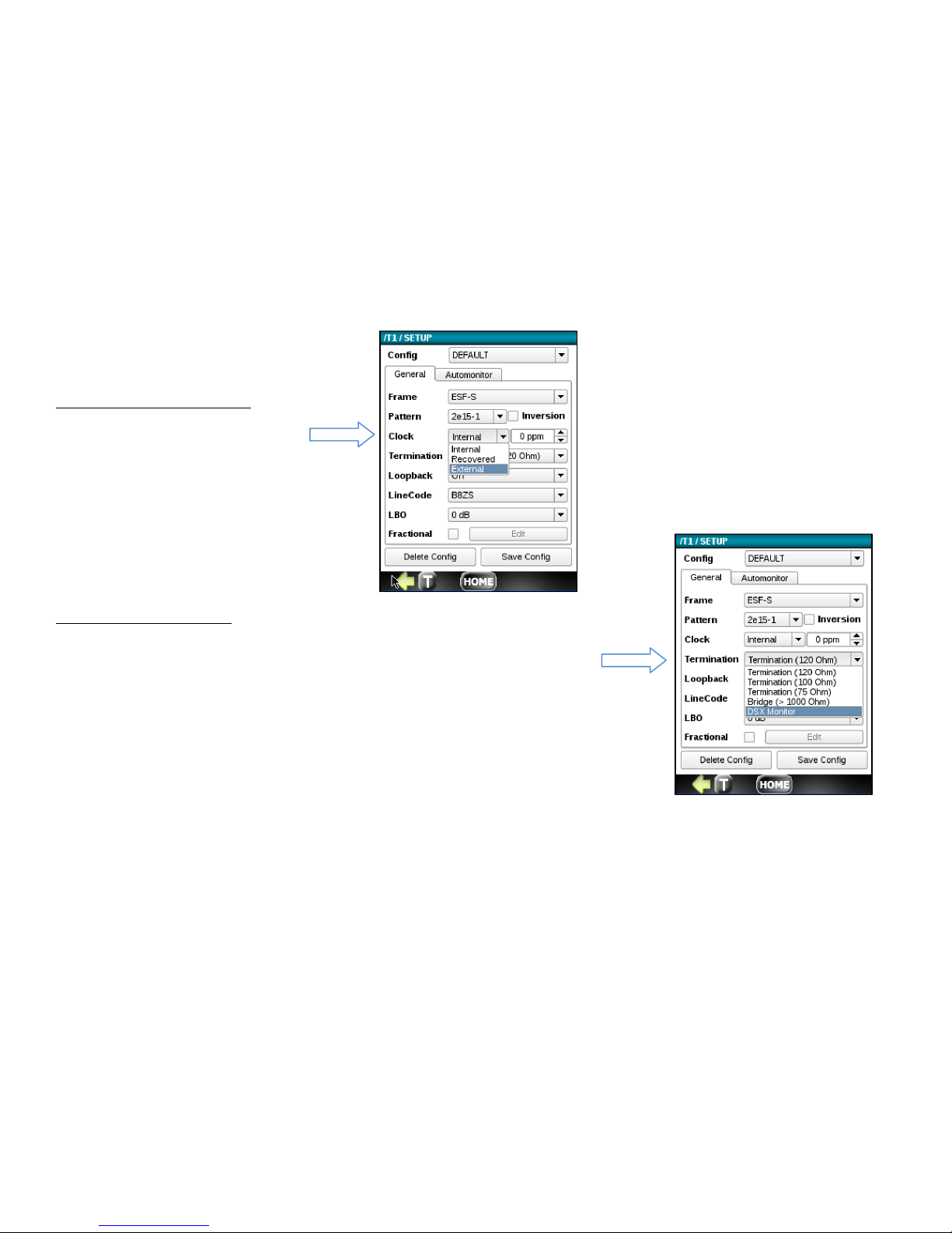
T1 Transmitter Clock Source
• Internal - from TCXO 3ppm
• Recovered - from Receive Data Rx
• External – from 0-5V TTL clock source
T1 Line Termination Type
• Termination - 120 Ohm, 100 Ohm, 75 Ohm, Tx and Rx software switchable
• Bridge – Input Rx impedance > 1kOhm, intended for monitoring T1 line on
• the outside plant circuit.
• DSX Monitor – 120/100 0r 75 Ohm termination on DSX test point. Typically
• provides 20 dB of attenuation across a 100 Ohm resistive load.
Page 66
66
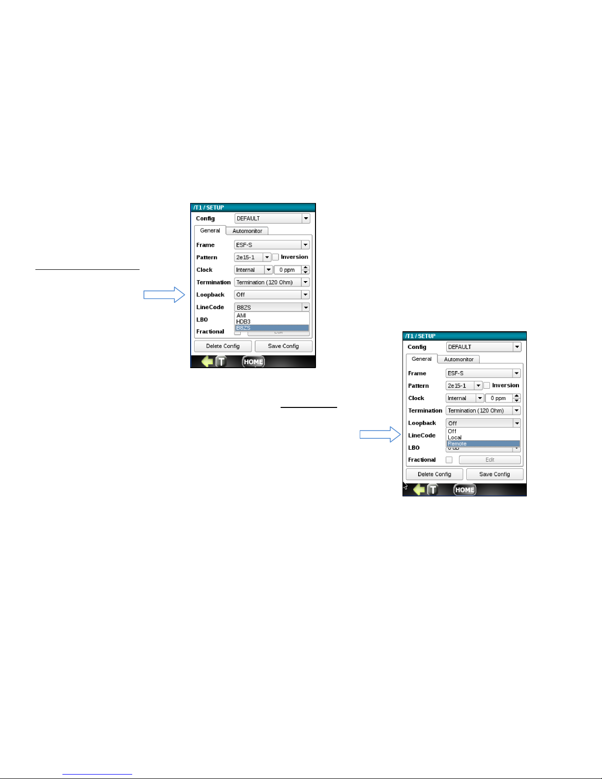
T1 Line Loopback Mode
• Local loop
• Remote Loop
T1 Lin
e Code
• AMI Code
• HDB3 code
Page 67
67
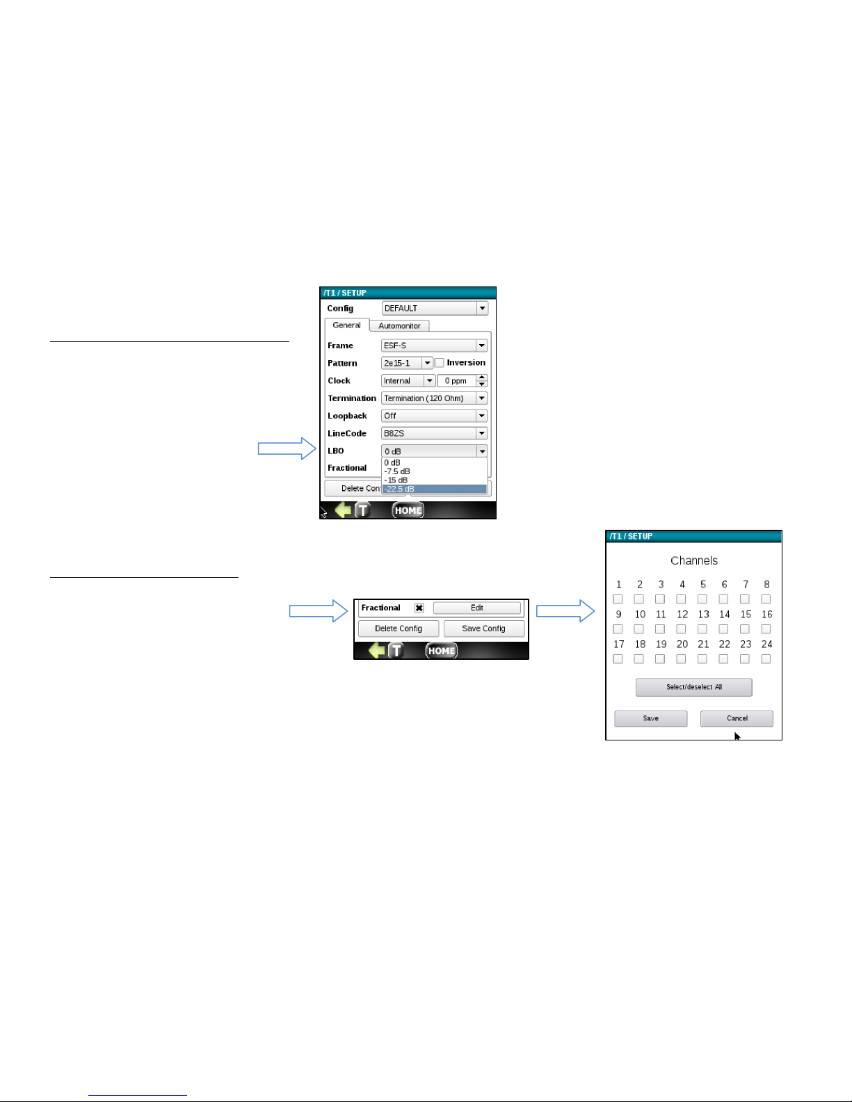
T1 Line Build Out Transmitter TX(LBO)
E1 Transmitter at 0 dB level or OFF
T1 Fractional Submenu Enable
To setup Fractional testing, click on
the checkbox labeled Fraction and press
the Edit button. Next, select desired
Timeslots for nx64kbps fractional T1
testing (where n =1 …24).
Page 68
68
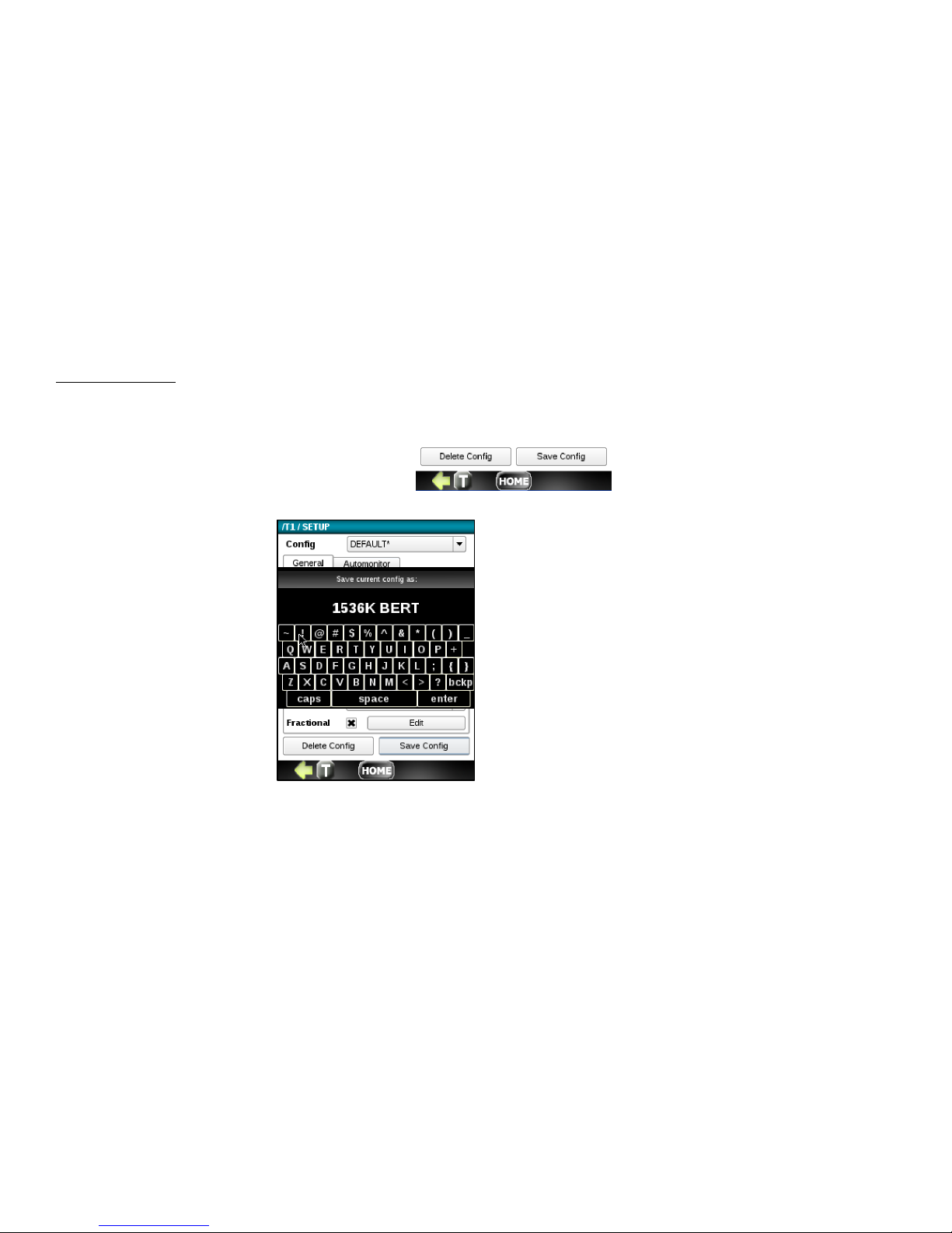
Saving the SETUP
The buttons labeled Delete Config and Save Config allow you to delete and save any configuration file currently shown in
the Config window. If the config is not saved, it will retain the last config used.
To save a config, press the Save Config button.
You can save as Default or you
can enter a new name for the
current configuration. To save,
press the enter button.
When you return the Setup
menu, you will see any new
configs created in the Config
drop down.
Page 69
69
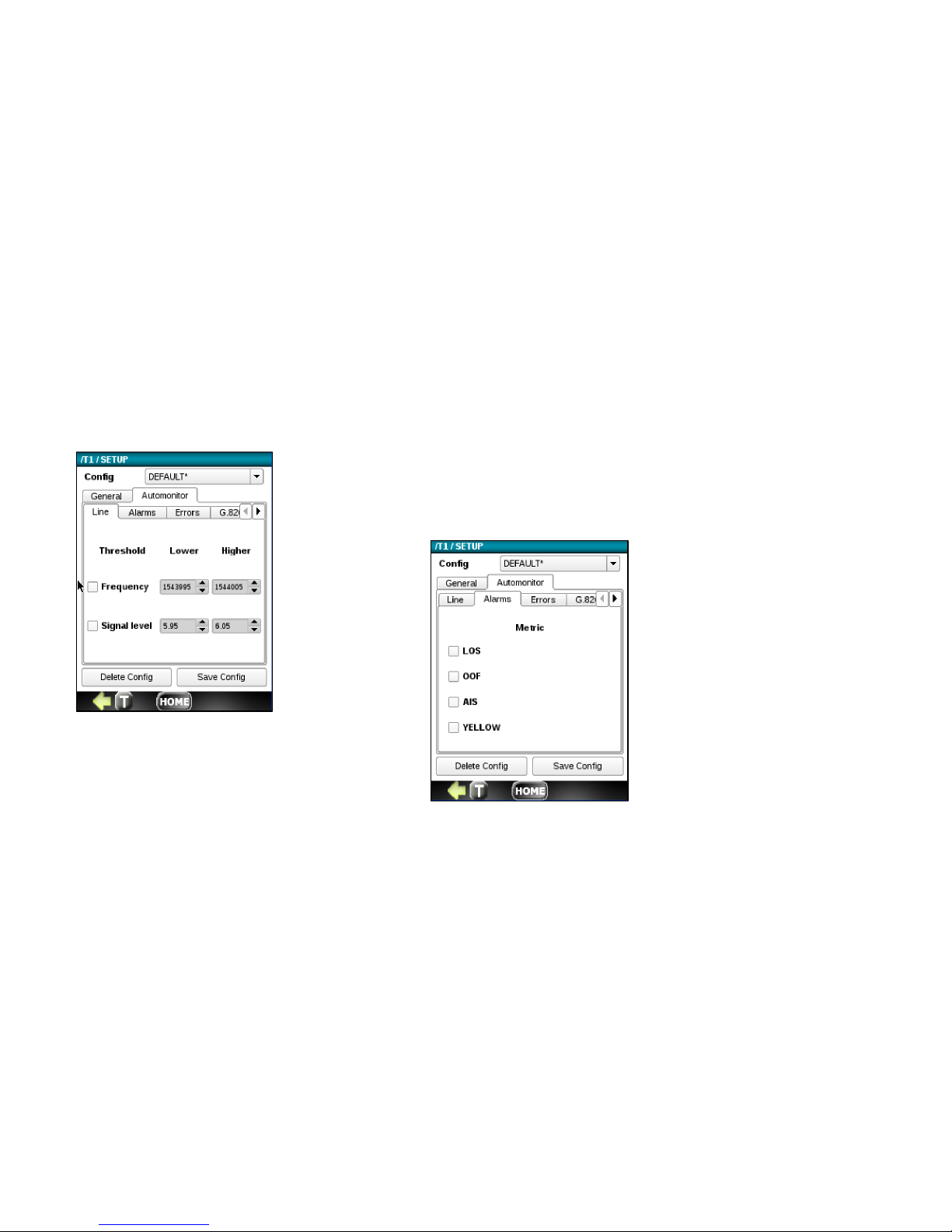
6.2.2 Automonitor Configuration Tab
L
ine Tab (Enable and Set Thresholds)
• Frequency (Hz)
• Signal Level (V)
Alarm Tab (Enable)
• LOS (Loss of Sync)
• OOF (Out of Frame)
• AIS (All 1’s Alarm Indicator Signal)
• Yellow
Page 70
70
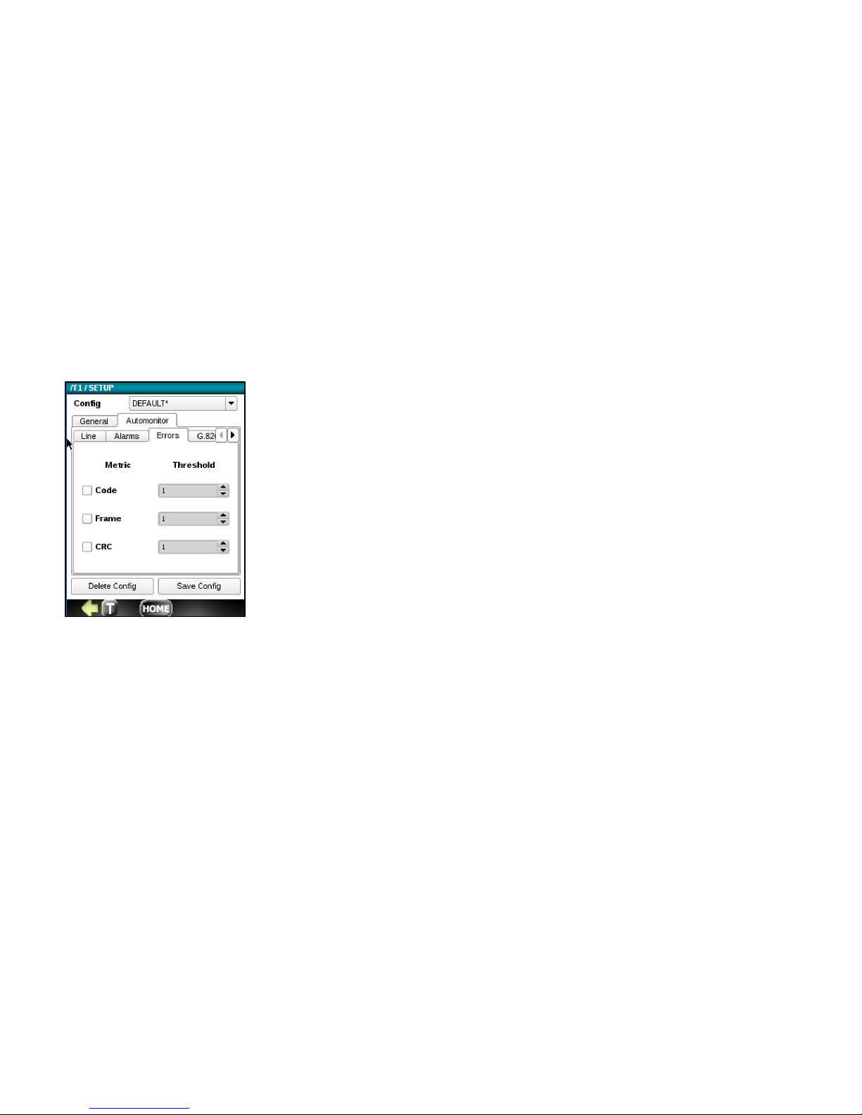
Errors Tab (Enable and Set Thresholds)
• Code
• Frame
• CRC
Page 71
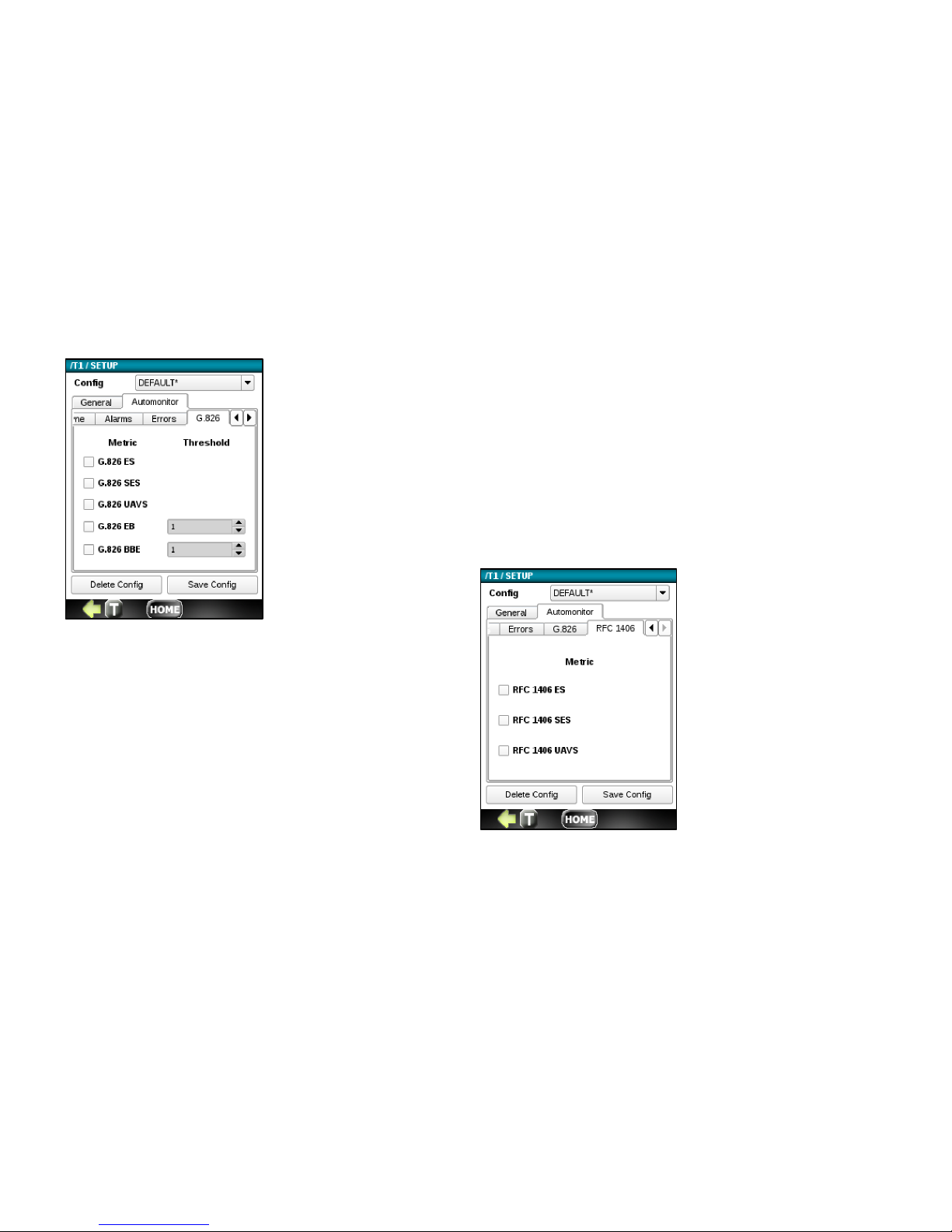
71
RFC1406 Tab (Enable)
• ES (Errored Seconds)
• SES (Severed ES)
• UAVS (Unavailable Seconds)
G.826 Tab (Enable)
• ES (Errored Seconds)
• SES (Severe ES)
• UAVS (Unavailable Seconds)
G.826 Tab (Enable and Set Thresholds)
• EB (Errored Block)
• BBE (Background Block Error)
Page 72
72
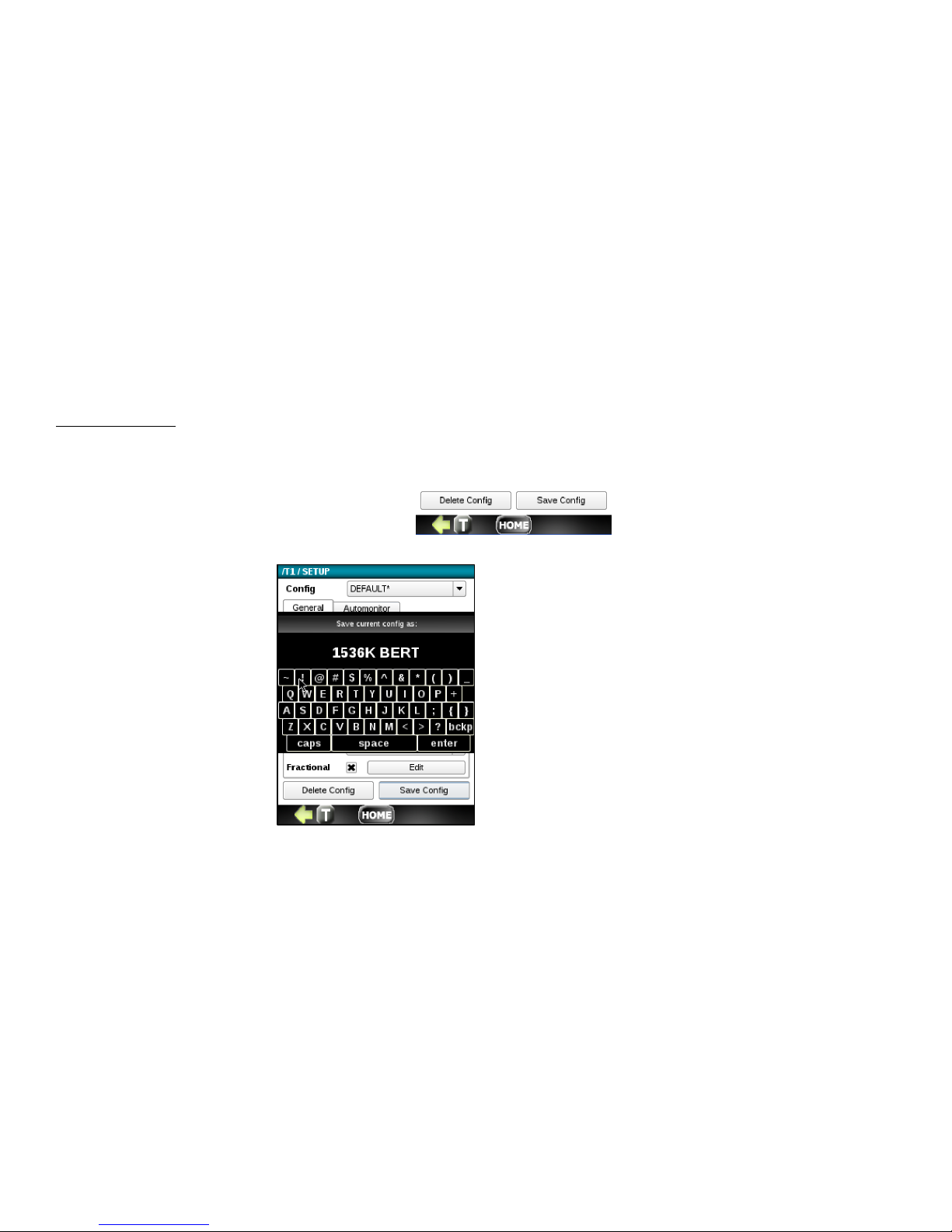
Saving the SETUP
The buttons labeled Delete Config and Save Config allow you to delete and save any configuration file currently shown in
the Config window. If the config is not saved, it will retain the last config used.
To save a config, press the Save Config button.
You can save as Default or you
can enter a new name for the
current configuration. To save,
press the enter button.
When you return the Setup
menu, you will see any new
configs created in the Config
drop down.
Page 73
73
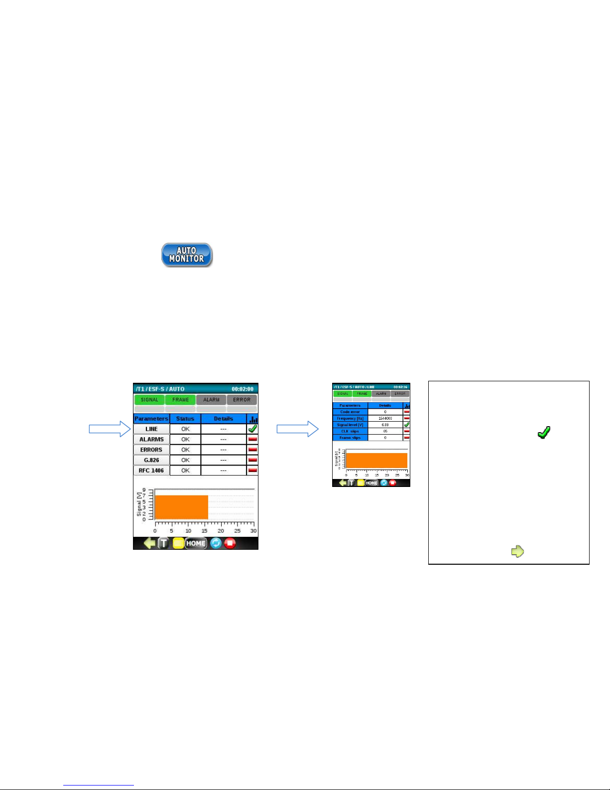
6.3 Auto Monitor
Run the AUTO MONITOR application to automatically check the tested T1 signal for the following Parameter categories:
Line Errors, Alarms, Errors, G.826 analysis and RFC1406 analysis.. For each, the status is displayed along with failure
details. The indicators at the top display the current and historical state of SIGNAL/FRAME/ALARM/ERROR events.
You can display additional sub-detail metrics for each category by clicking on a Parameter category name button. For
instance, click on the Line button to display detail metrics for Code errors, Frequency and more. See example below.
Tips:
Click in the histogram column to
display a histogram for the
corresponding metric.
Click a box under
SIGNAL/FRAME/ALARM/ERROR
to reset the history of that
event.
Green arrows at the bottom
may be used to display
additional information for a
metric category.
Page 74
74
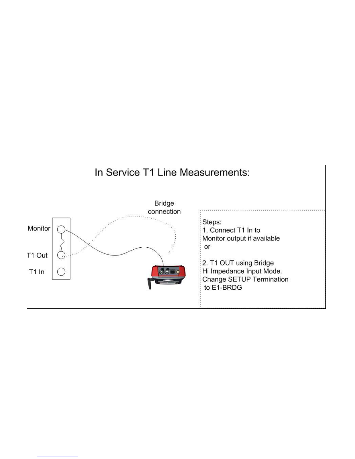
To run the Auto Monitor test, connect the NetProbe 2000 T1 receiver to either a DSX MON jack or E1OUT for BRIDGE if
DSX MON jack is not available. Connect the T1 signal to the appropriate connector (RJ-45, COAX, Bantam) on the
NetProbe. The transmitter Tx is disabled by default.
Page 75
75
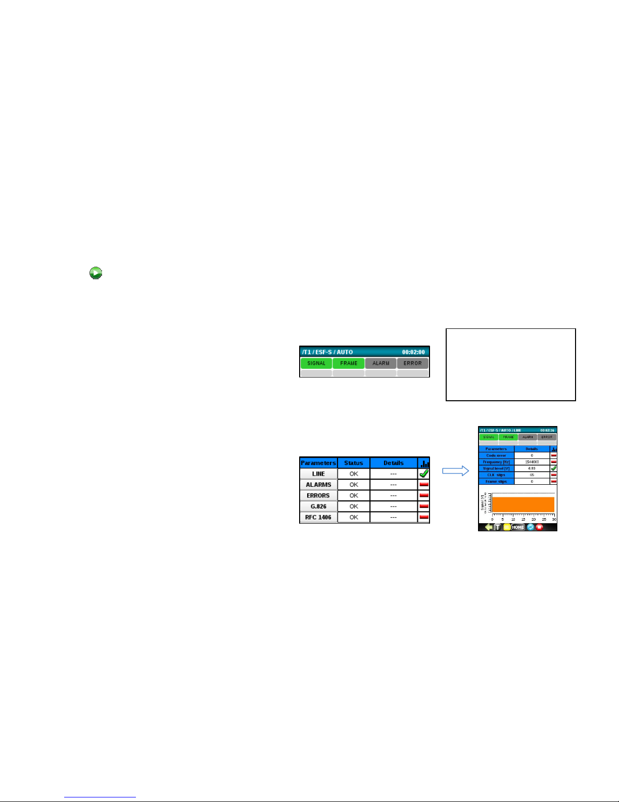
Next, press button to start the AUTO MONITOR test.
Check the AUTO MON main screen and observe the following:
• The real-time SIGNAL and FRAME (with
Framed data) indicators at the top of the
screen are Green. Red indicates a problem.
If these indicators are red, check all circuit
connections and T1 setup
• The history indicators below are gray. Red
indicates a problem. If an event
(SIGNAL/FRAME/ALARM/ERRROR) occurs,
the corresponding gray history area will
remain red until it is reset.
• STATUS boxes report OK. If not, check under
DETAILS, if available, or click on a Parameter
category name to display sub-detail metrics.
The OK/Fail thresholds are configured under
the Setup Automonitor tabs.
Tip:
Click on a history indicator
box or a Status box to reset
the corresponding event or
status.
Page 76
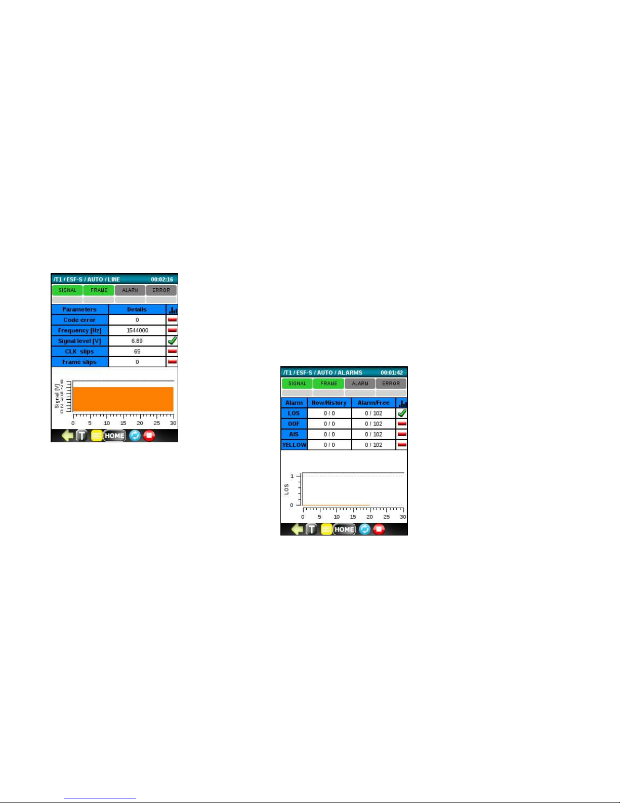
76
Each category and its sub-detail metrics are described below.
Line measurements
• Code Errors
• Frequency
• Signal Level
• Clock Slips
• Frame Slips
Alarms
• LOS (Loss of Sync)
• OOF (Out of Frame)
• AIS (All 1’s Alarm Indicator Signal)
• Yellow
Page 77
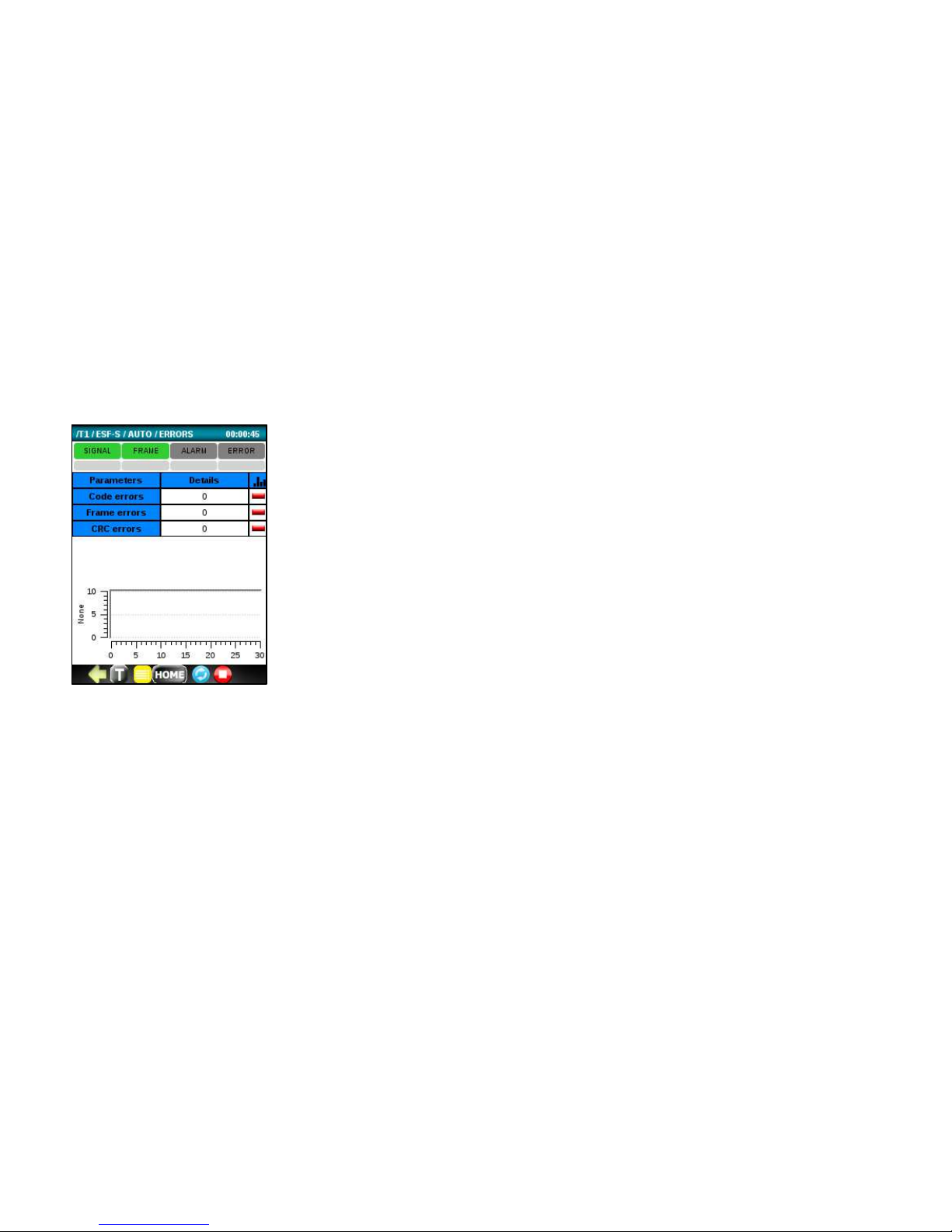
77
Errors
• Code
• Frame
• CRC
Page 78
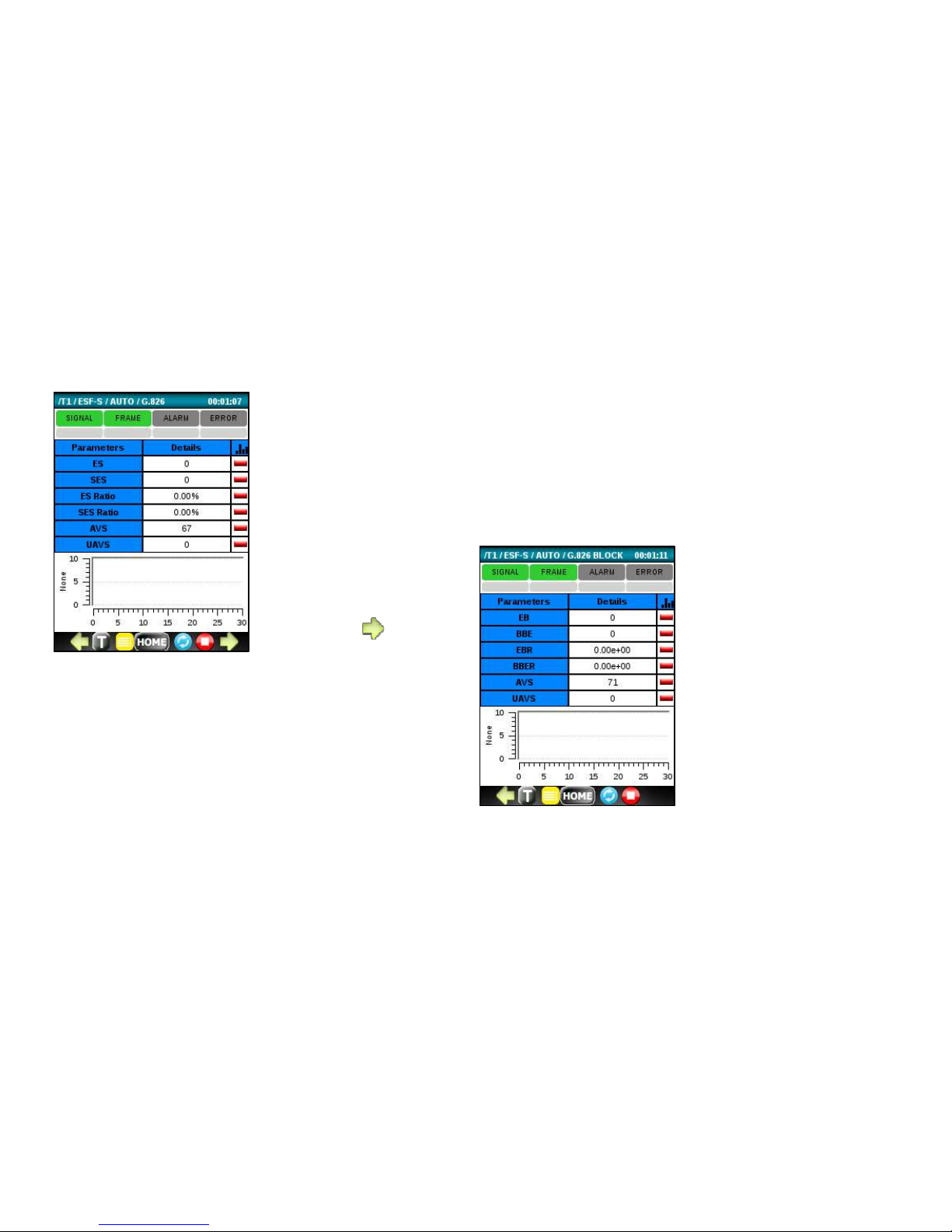
78
G.826
• ES (Errored Seconds)
• SES (Severe ES)
• ES Ratio %
• SES Ratio %
• AVS (Available Seconds)
G.826
Block
• EB (Errored Block)
• BBE (Background Block
Error)
• EBR (EB Ratio %)
• BBER BBE Ratio %)
• AVS (Available Seconds)
•
UAVS (Unavailable Seconds)
Page 79
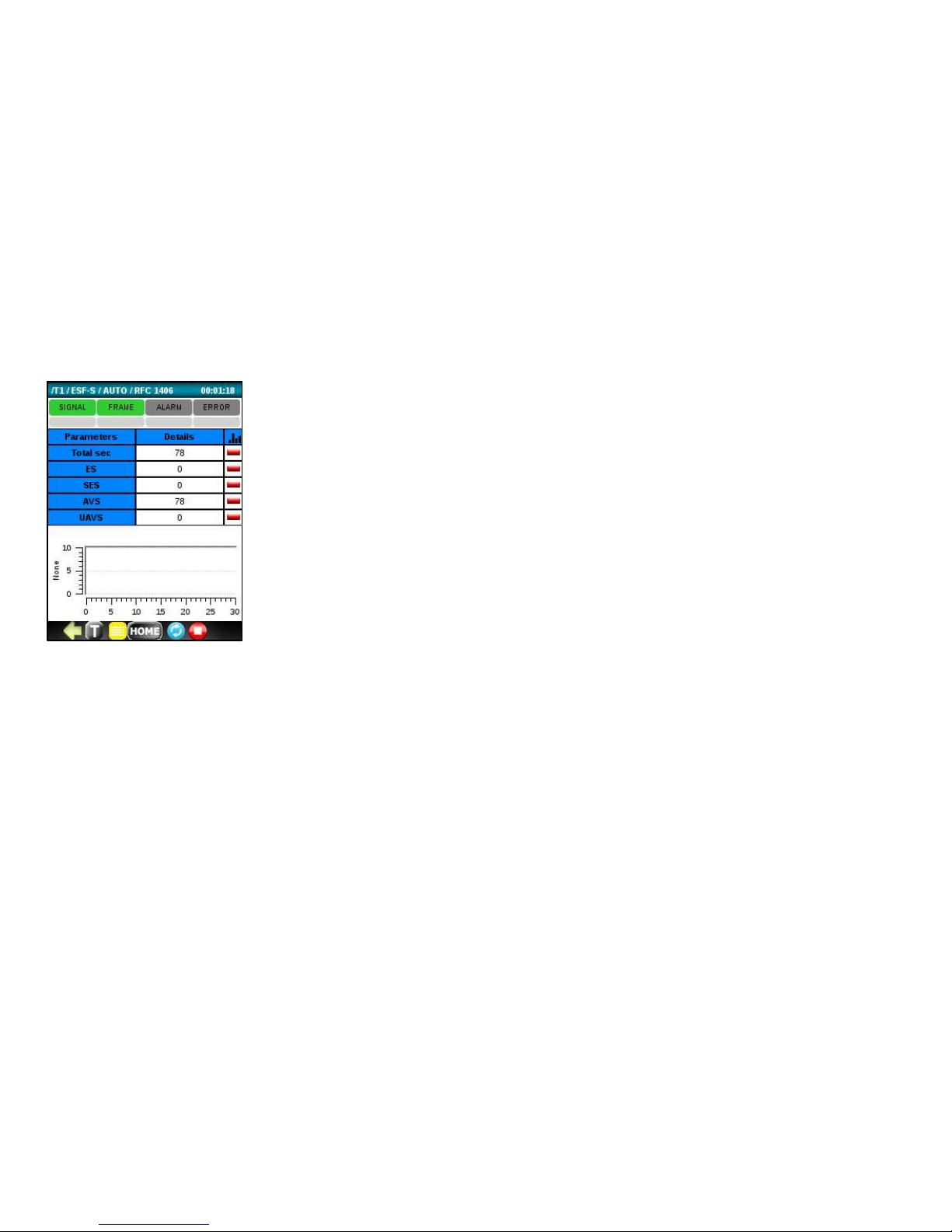
79
RFC1406
• Total Seconds
• ES (Errored Seconds)
• SES (Severed ES)
• AVS (Available Seconds)
• UAVS (Unavailable Seconds)
Page 80
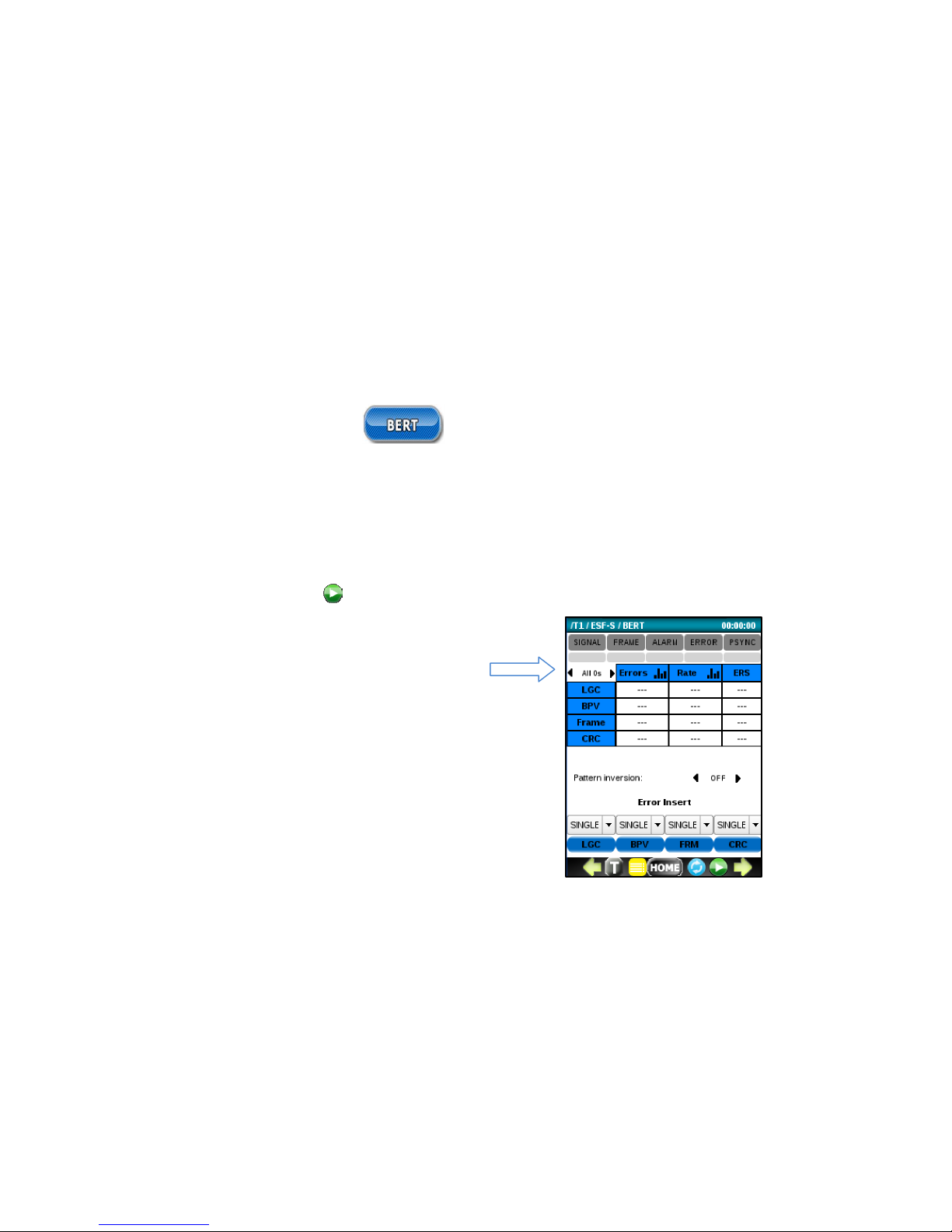
80
6.4 Bit Error Testing (BERT)
Run the BERT application to check the integrity of an E1 circuit. It can be run with a loopback or end to end with another
test set. The indicators at the top display the current and historical state of SIGNAL/FRAME/ALARM/ERROR/PSYNC
events. The test results are reported as errors or error rates. Any events, including Alarms and G.821 metrics, are also
reported.
Before you start transmitting with the button, you can easily select a test pattern. In the example below, a test
pattern of 2e15-1 is selected with no inversion.
A default BERT test pattern is 2
-15-
1. Other patterns can
be selected from the list by scrolling left or right. Choices
include OFF, 63, 511, 2047, 2-15-1, 2-21-1, 2-23-1, QRSS,
All 0’s, All 1, 1:3, 1:7, 1:15, 1:31. The pattern can also be
configured in Setup.
Page 81
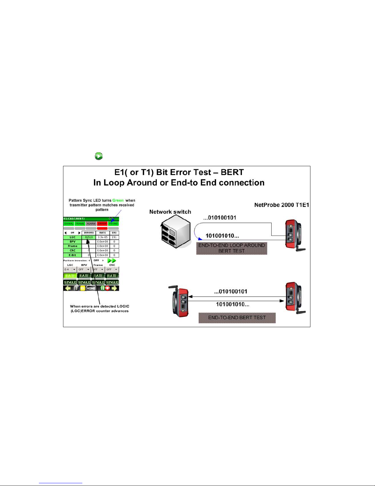
81
A typical loop around or point-to-point Bit Error Test setup is shown below. After the bantam, BNC or RJ-45 cable
connection is made; press to start the BERT test.
Page 82
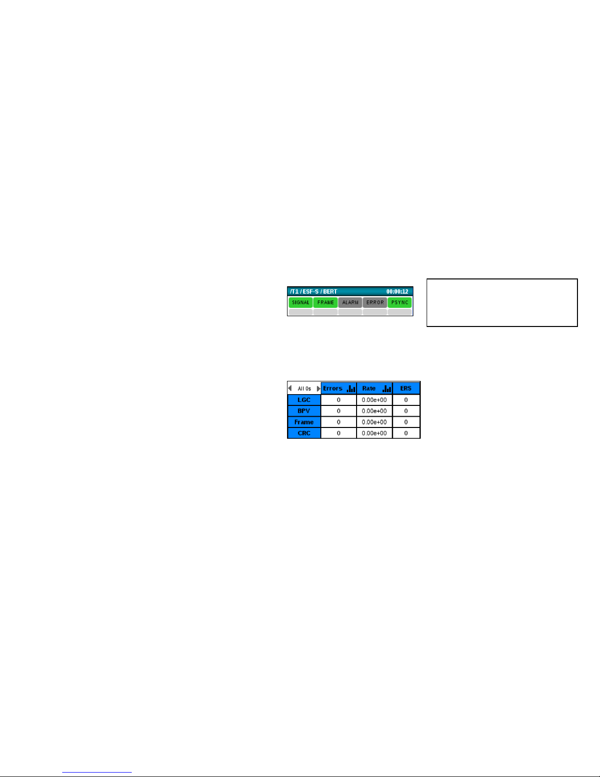
82
Check the BERT main screen and observe the following:
• The real-time SIGNAL, PSYNC and FRAME
(with Framed data) indicators at the top of
the screen are Green. Red indicates a
problem. If these indicators are red, should
check all circuit connections and T1 setup.
• The history indicators below are gray. Red
indicates a problem. If an event
(SIGNAL/FRAME/ALARM/ERRROR/PSYNC)
occurs, the corresponding gray history area
will remain red until it is reset.
• Error counters report 0 or at least are not
quickly incrementing. If these are quickly
incrementing, check all circuit connections
and T1 setup.
Tip:
Click on any history indicator box
to reset all history indicators.
Page 83
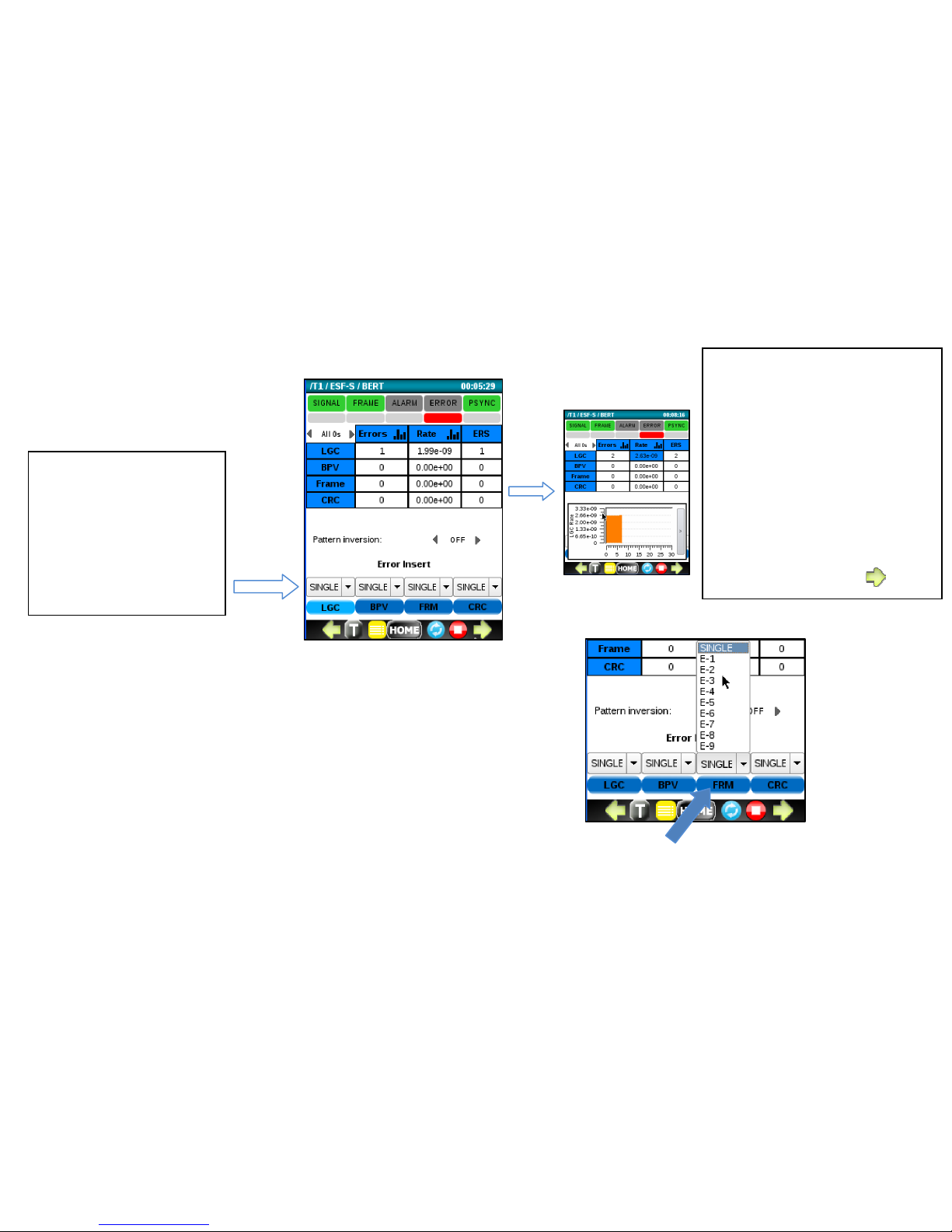
83
Optionally, a constant bit error rate can be injected using the RATE menu.
Select a rate from the pull down menu and press the corresponding
green button to begin the error RATE injection.
Tip:
Click in the Errors or Rate
columns to display a histogram
for the corresponding metric.
Click on the thin gray bar to
hide it.
Green arrows at the bottom
can be used to display
additional metrics, alarms and
timeslot information.
Tip:
To verify that everything
is setup properly after
starting BERT, click on
the LGC button to force
and detect a single bit
error.
Page 84
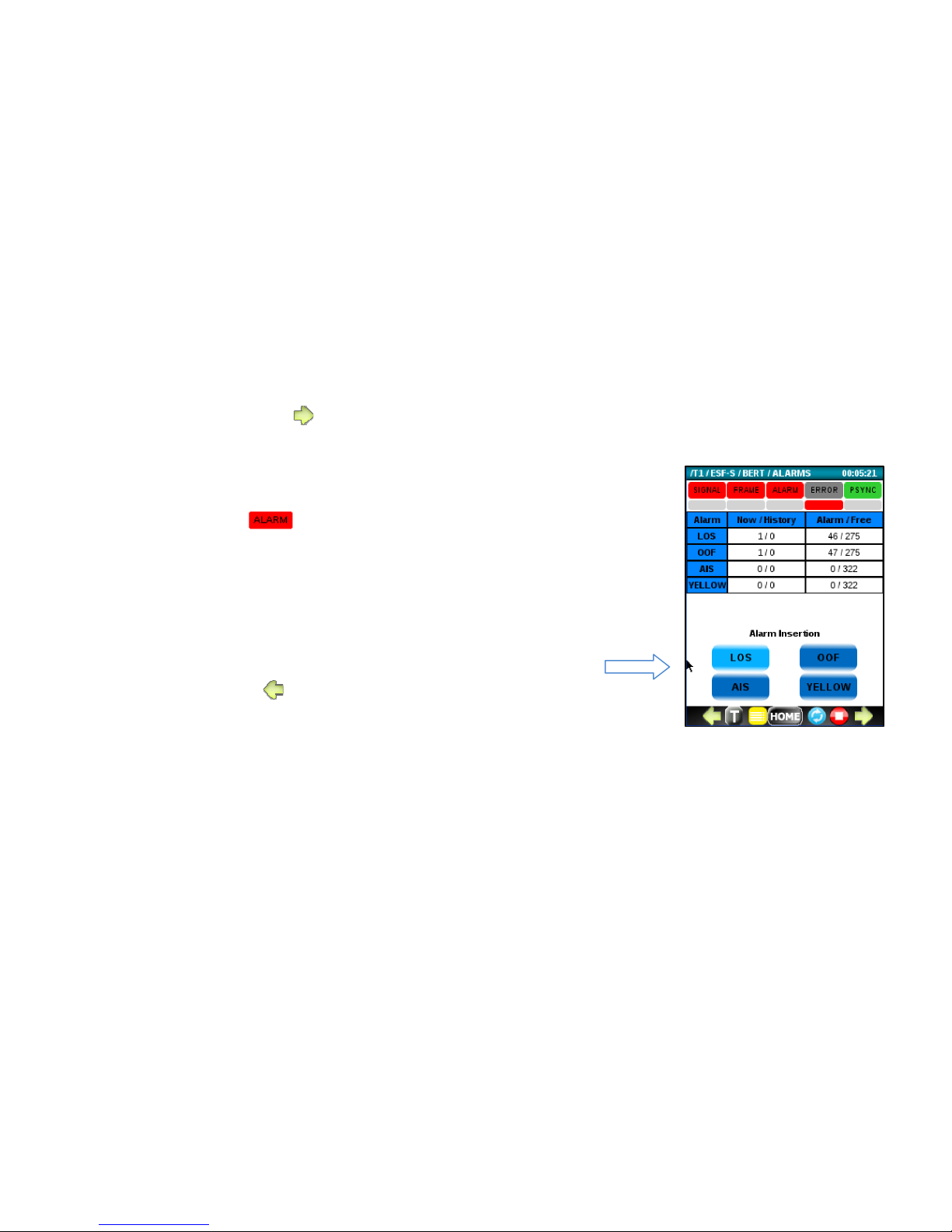
84
6.4.1 ALARM menu
To access the Alarms menu, press from the main BERT screen.
Use this menu to:
• Monitor the current and history alarm status to determine which alarms
caused the LED to turn red.
• Force an alarm condition onto the E1 line by pressing an Alarm Insertion
button. Caution: The alarm insertion will be continuous until pressed
again.
o LOS (Loss of Signal)
o OOF (Out of Frame)
o AIS (All 1’s Alarm Indicator Signal)
o Yellow
• To exit, press .
Page 85
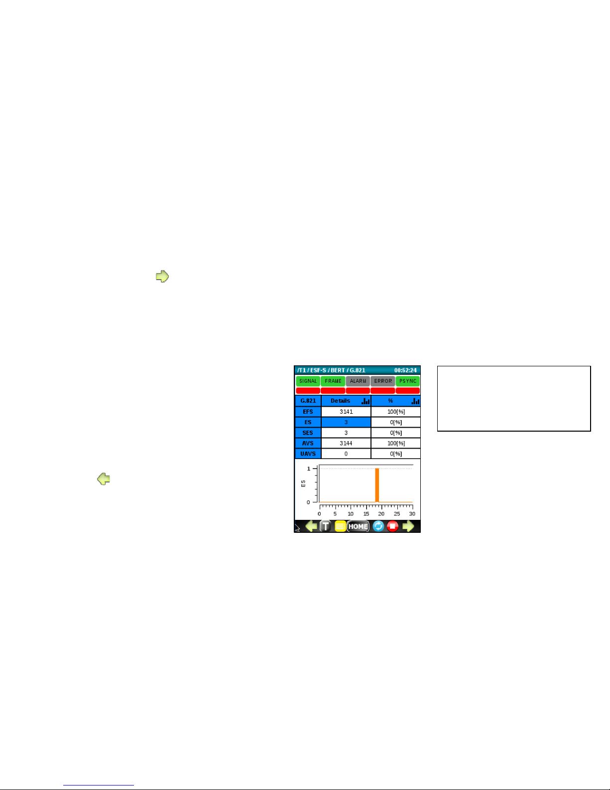
85
6.4.2 G.821 ERROR menu
To access this menu, press from the ALARM menu.
Use this menu to:
• Monitor the current and history ERROR
status to determine the severity of the
errors that generated an ERROR indication.
• Monitor G.821 counters and percentages.
o EFS (Error Free Seconds)
o ES (Errored Seconds)
o SES (Severe ES)
o AVS (Available Seconds)
o UAVS (Unavailable Seconds)
• Display a histogram
To exit, press .
Tip:
Click in the Details or %
columns to display a histogram
for the corresponding metric.
Page 86
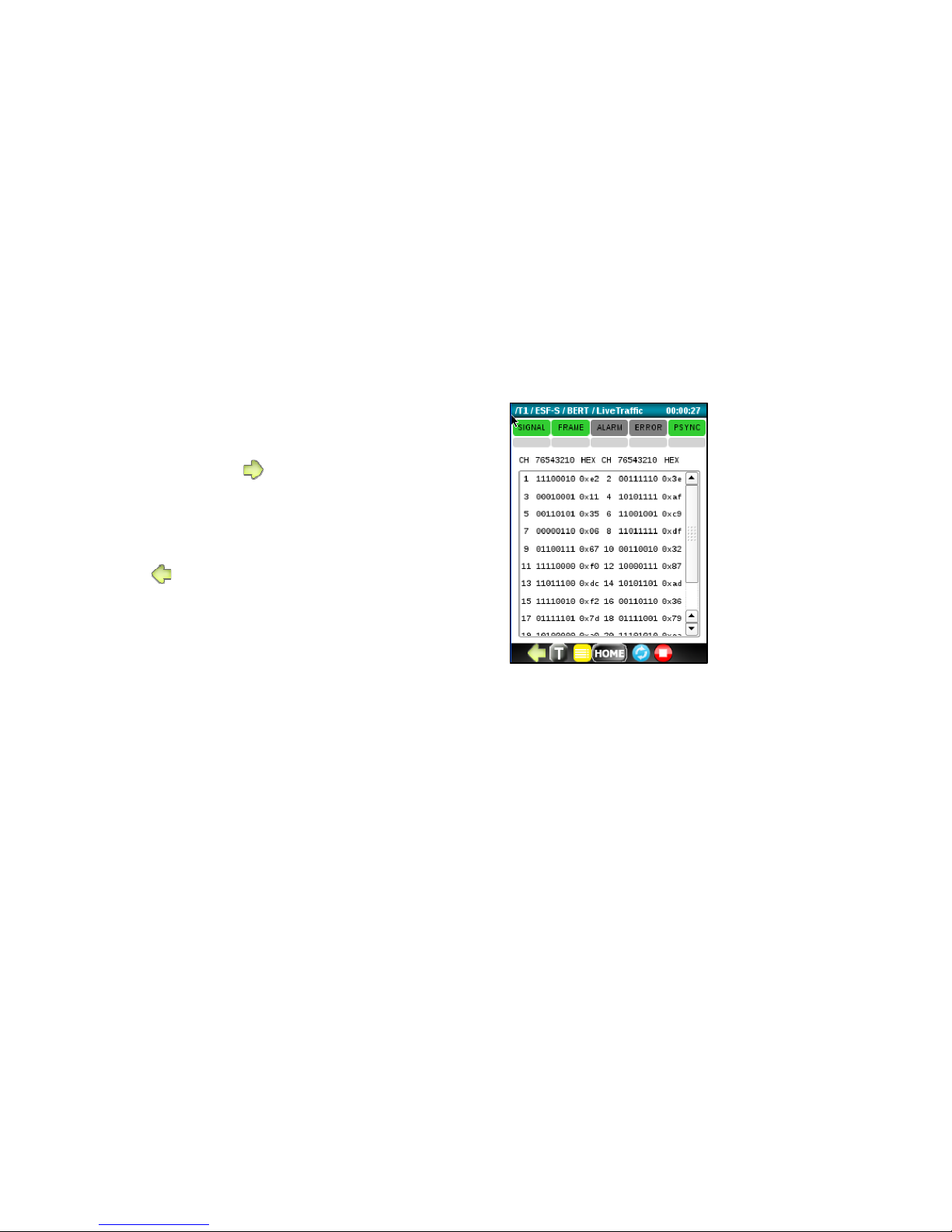
86
6.4.3 Live Traffic menu
To access this menu, press from the G.821 ERROR menu.
Use this menu to view the binary and hexadecimal
value in each channel.
To exit, press .
Page 87
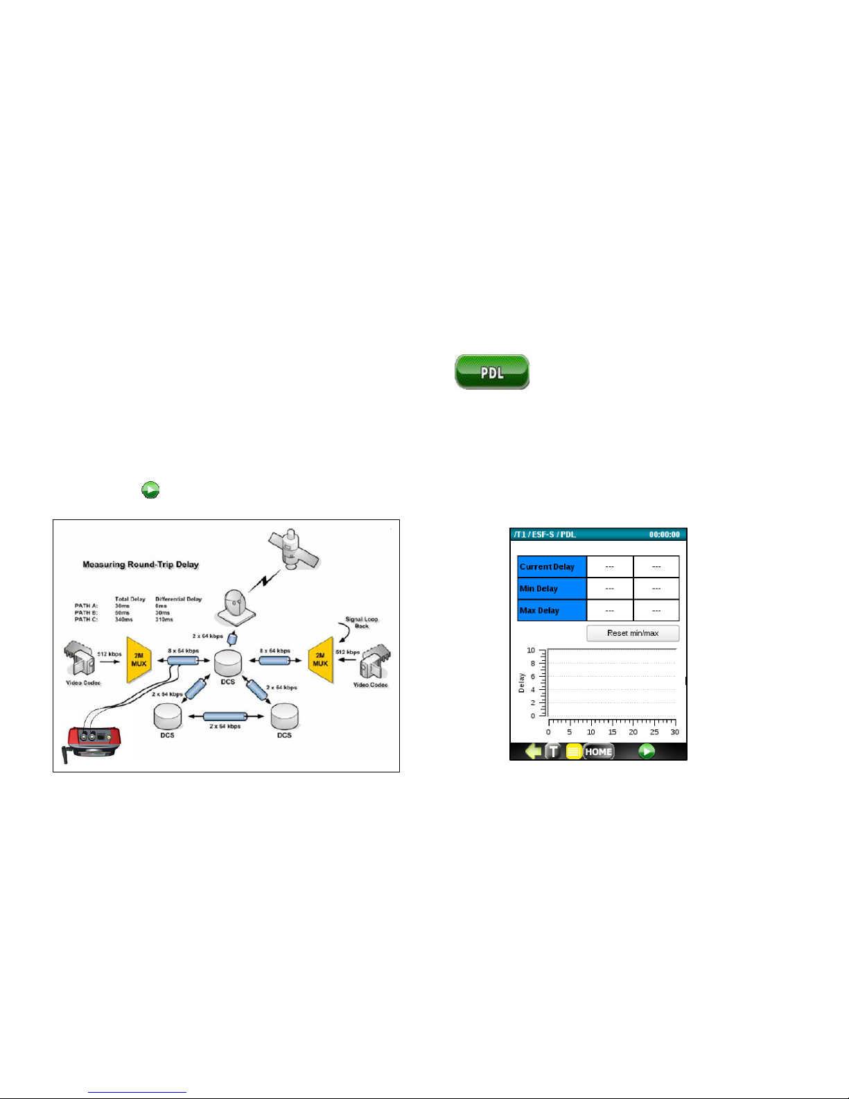
87
6.5 Propagation Delay Measurement (PDL)
Run the Propagation Delay Measurement application to measure the round trip loopback delay around the T1 circuit
heck the integrity of a T1 circuit.
A typical loop around connection for measuring PDL is shown below. After the bantam, BNC or RJ-45 cable connection
is made; press to start the PDL measurement.
Page 88
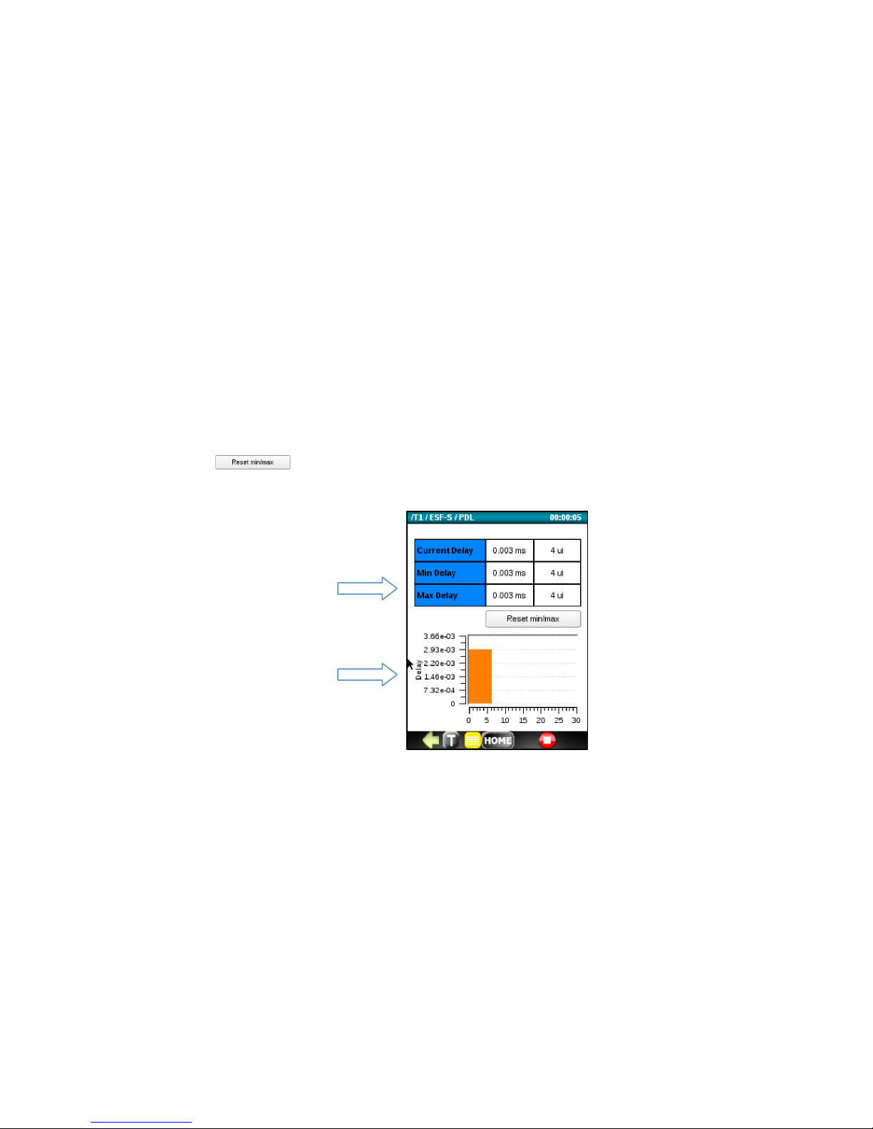
88
When the PDL measurement begins, the tester will first reset the displayed results and then calibrate. After a couple
seconds, the Current Delay, Minimum Delay and Maximum Delay values will display along with a histogram.
The Current Delay, Minimum Delay and Maximum Delay is measured and reported in milli-seconds (ms) and unit
intervals (ui’s). Press the button to reset the Min Delay and Max Delay values.
Page 89
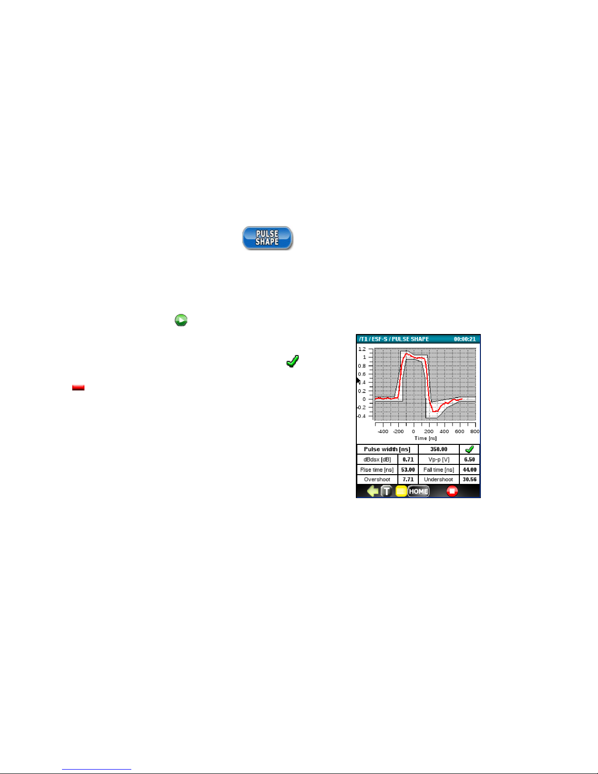
89
6.6 Pulse Shape Analysis (PSA)
Run the Pulse Shape Analysis (PSA) application to check if the T1 pulse shape complies with ITU-T G.703 specifications.
To plot and analyze the T1 pulse shape, first connect the T1 signal to be tested and select the appropriate Termination
from the T1 Setup menu. Press to start the PSA test.
If the pulse can be normalized it will plot inside the G.703 template. If
the pulse fits 100% inside the template, the test PASSED ( ). If any
part of the plot of the plot falls outside of the template, the test
FAILED ( ).
Page 90
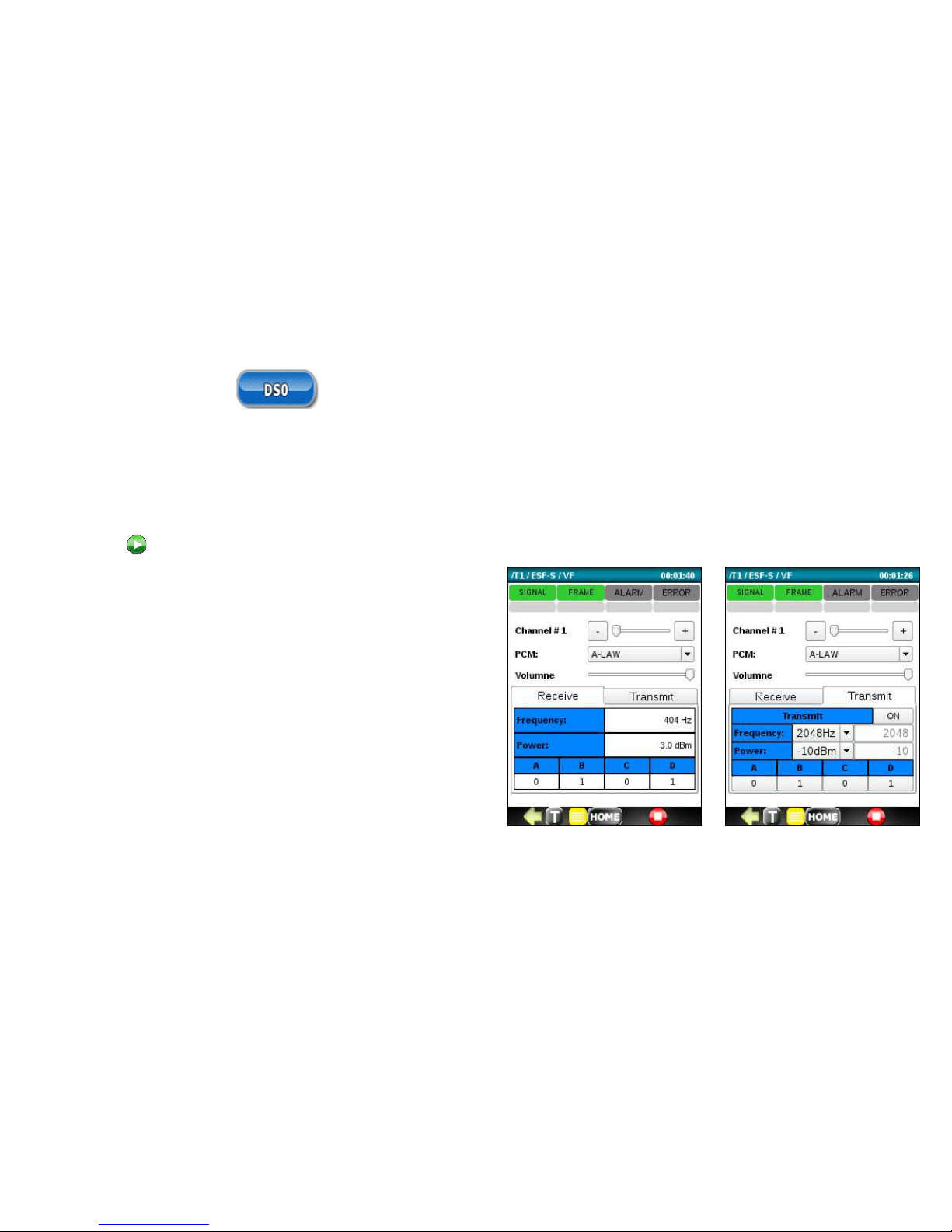
90
6.7 DS0 Testing
Run the DSO Testing application to measure the frequency and power of any received tones and monitor the ABCD bits
of a DSO sub channel. The application also allows you to listen to the audio in a timeslot using the supplied headset.
To run a DSO test, connect the T1 signal to be tested, select a timeslot number, select PCM Companding (u-Law/A-Law)
and press to start a DSO test.
DS0 testing includes:
• Listening to any of the 24 DS0 Voice Channels using
the supplied headset.
• Measuring the frequency of the received signal. Test
tones are typically 404Hz, 1004Hz, and 1804Hz.
• Measuring the power (dBm) of the received test
tones. If the reading is not available, N/A will display.
• Reading the ABCD bits for the selected timeslot.
• Transmitting signal 300-3404Hz, -40.0-3.0dBm.
• Configuring ABCD bits for the selected timeslot.
Page 91
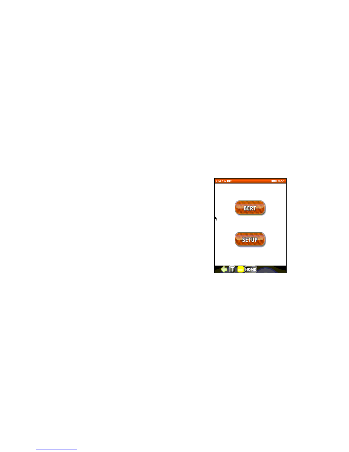
91
7. T3 ANALYZER OPTION
7.1 Top Menu
The T3 analyzer option starts up with the top menu shown to the right. It
Includes the following test functions:
BERT
SETUP
Page 92
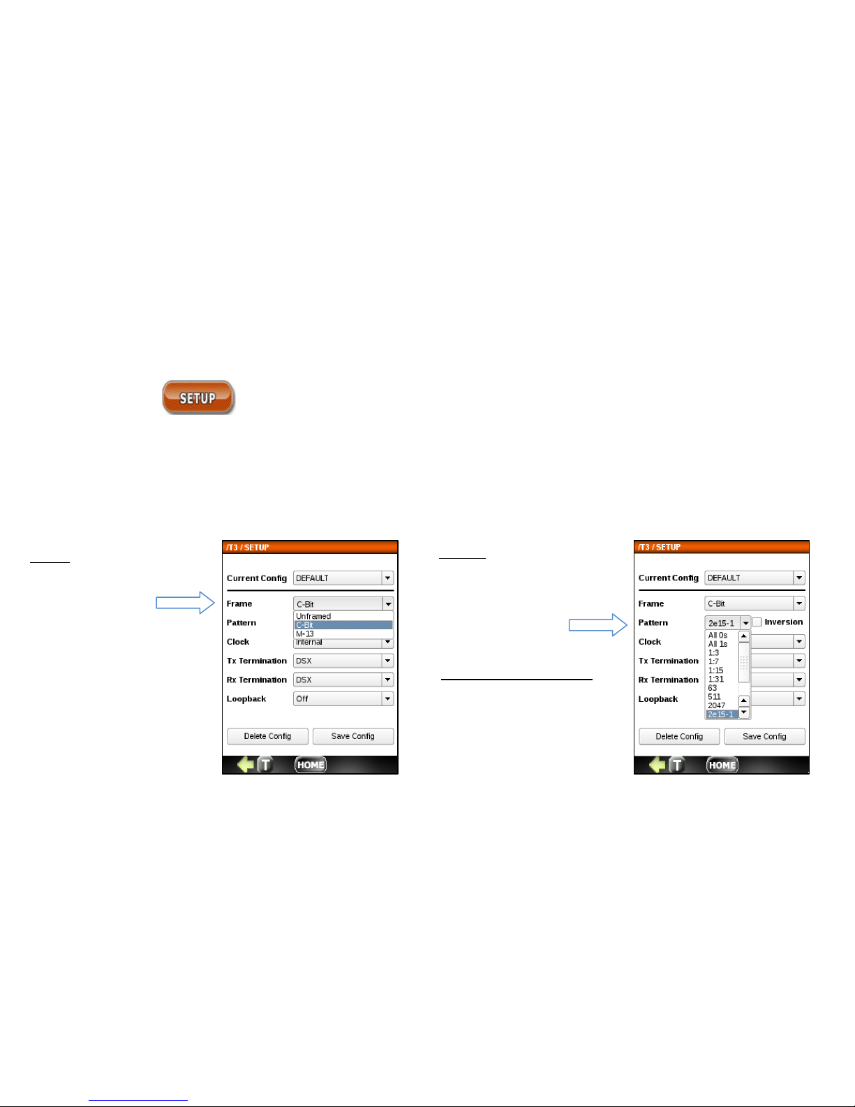
92
7.2 Set Up
Use the Setup menu to configure the T3 transmitter and receiver parameters.
Each configuration parameter is described below:
Pattern
OFF, 63, 511, 2047, 2-15-1, 221-1, 2-23-1, QRSS, All 0’s, All
1, 1:3, 1:7, 1:15, 1:31. The
pattern can also be
configured in Setup.
Frame
• Unframed – all
bits used for
data
• AMI Code
• C-Bit
• M-13
T
est Length (not shown)
Unlimited, 30 s, 1 min, 5 min,
10 min, 30 min, 1hr, 3 hr. 6 hr,
12 hr, 1 day, 2 days, 3 days,
Page 93
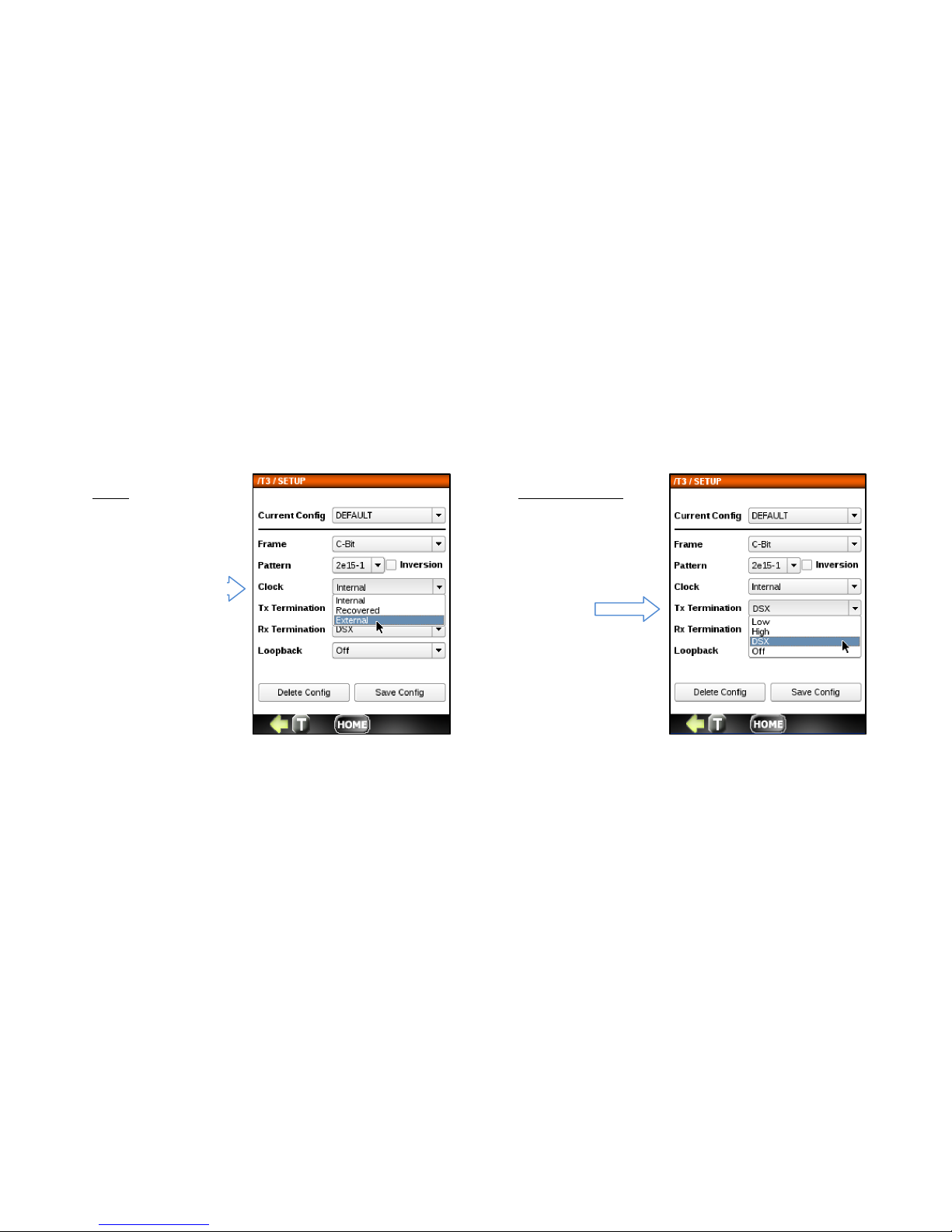
93
Clock
• Internal
• Recovered
• External
Tx Termination
• Low
• High
• DSX
•
Off
Page 94
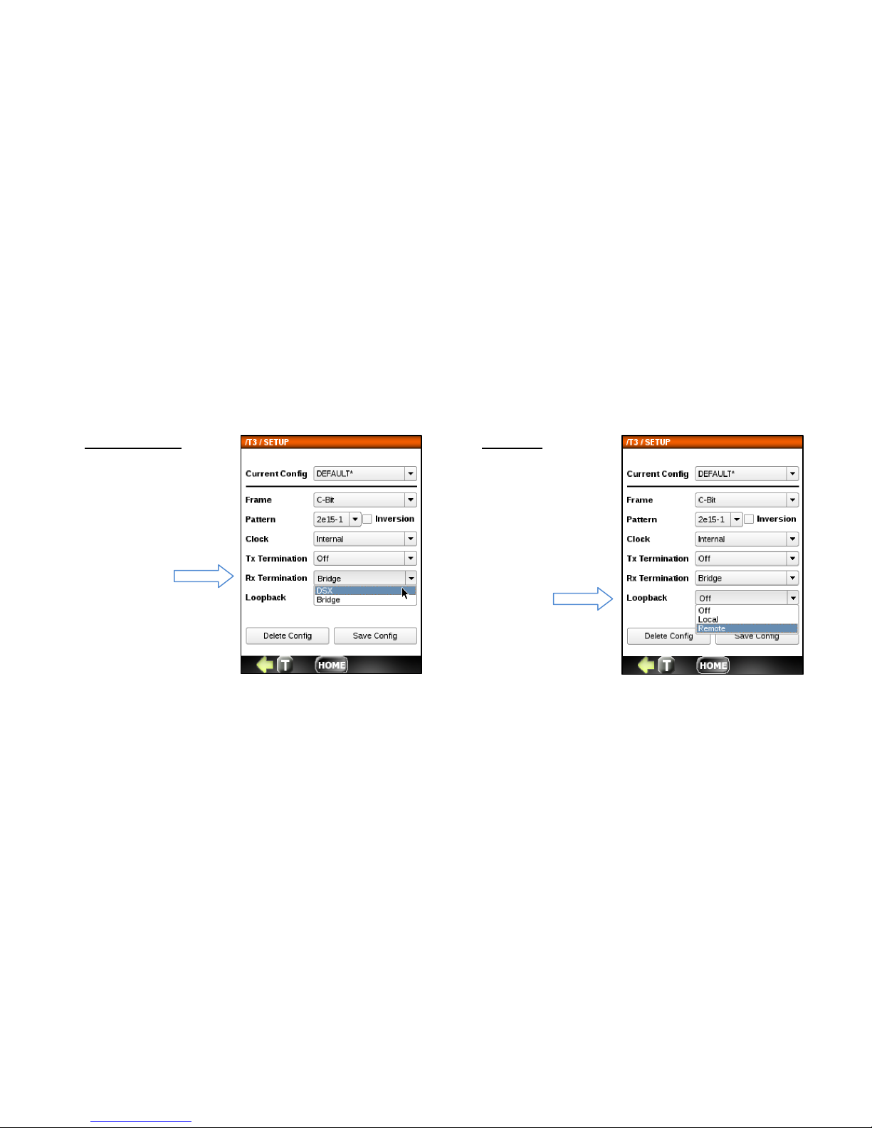
94
Rx Termination
• DSX
• Bridge
Loopback
• Off
• Local
• Remote
Page 95
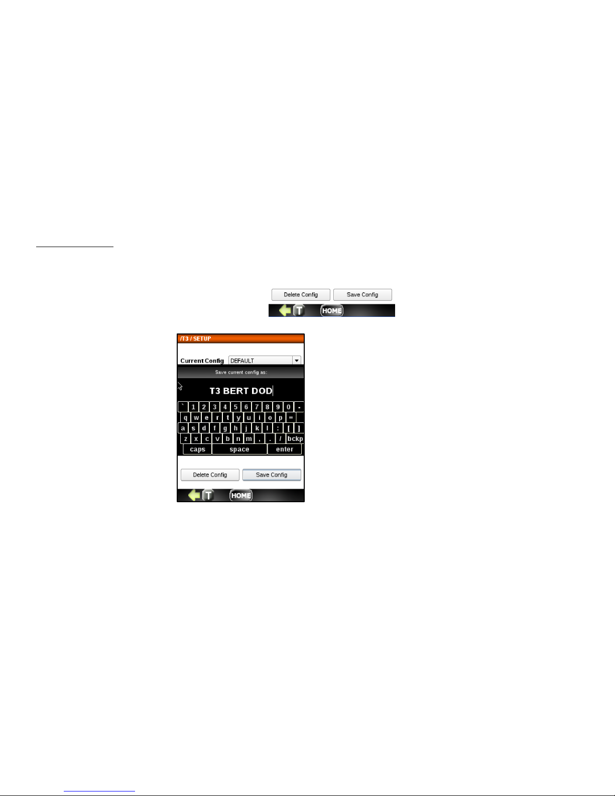
95
Saving the SETUP
The buttons labeled Delete Config and Save Config allow you to delete and save any configuration file currently shown in
the Config window. If the config is not saved, it will retain the last config used.
To save a config, press the Save Config button.
You can save as Default or you
can enter a new name for the
current configuration. To save,
press the enter button.
When you return the Setup
menu, you will see any new
configs created in the Config
drop down.
Page 96
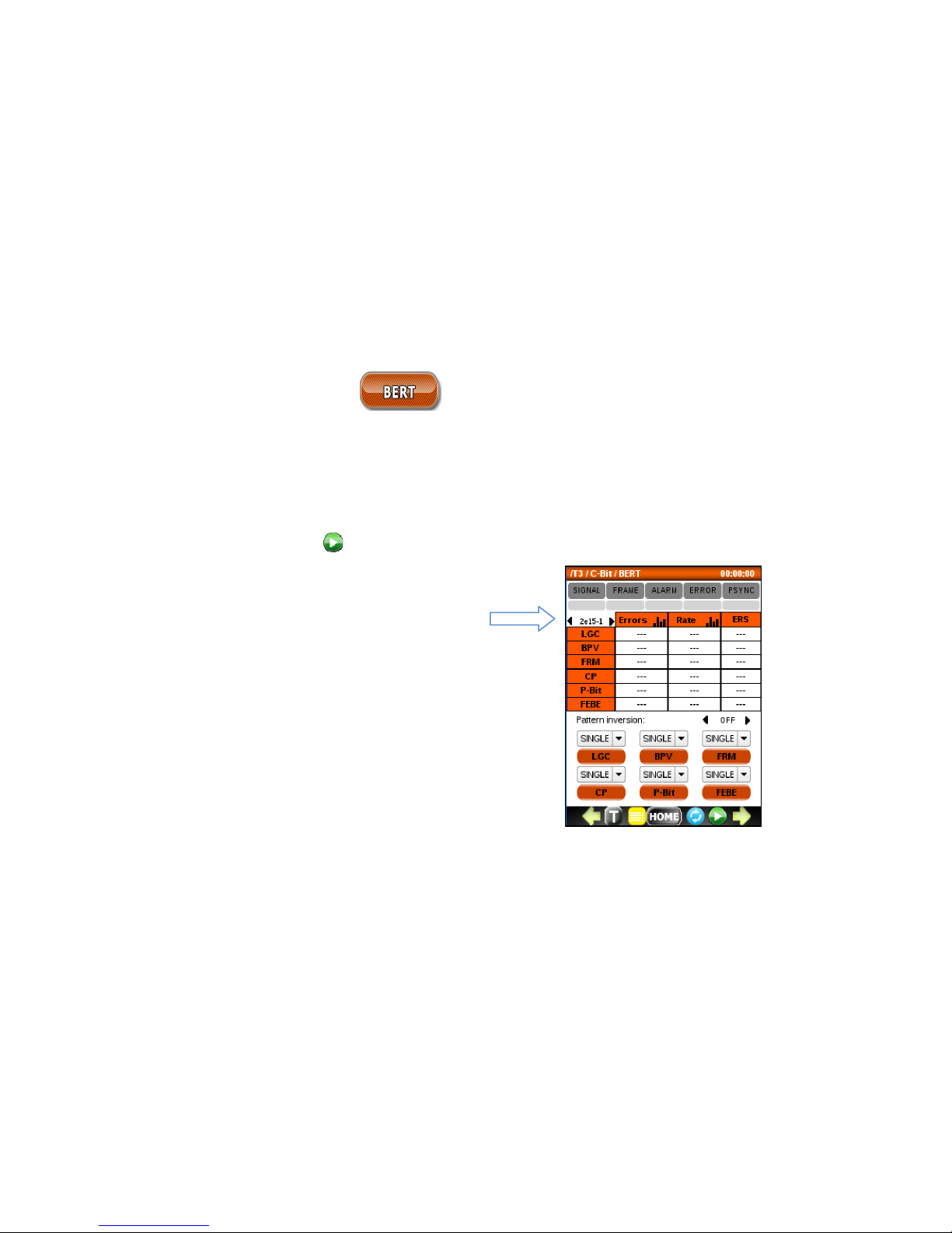
96
7.3 Bit Error Testing (BERT)
Run the BERT application to check the integrity of a T3 (DS3) circuit. It can be run with a loopback or end to end with
another test set. The indicators at the top display the current and historical state of
SIGNAL/FRAME/ALARM/ERROR/PSYNC events. The test results are reported as errors or error rates. Any events,
including Alarms and G.821 metrics, are also reported.
Before you start transmitting with the button, you can easily select a test pattern. In the example below, a test
pattern of 2e15-1 is selected with no inversion.
A default BERT test pattern is 2
-15-
1. Other patterns can
be selected from the list by scrolling left or right. Choices
include OFF, 63, 511, 2047, 2-15-1, 2-21-1, 2-23-1, QRSS,
All 0’s, All 1’s, 1:3, 1:7, 1:15, 1:31. The pattern can also be
configured in Setup.
Page 97
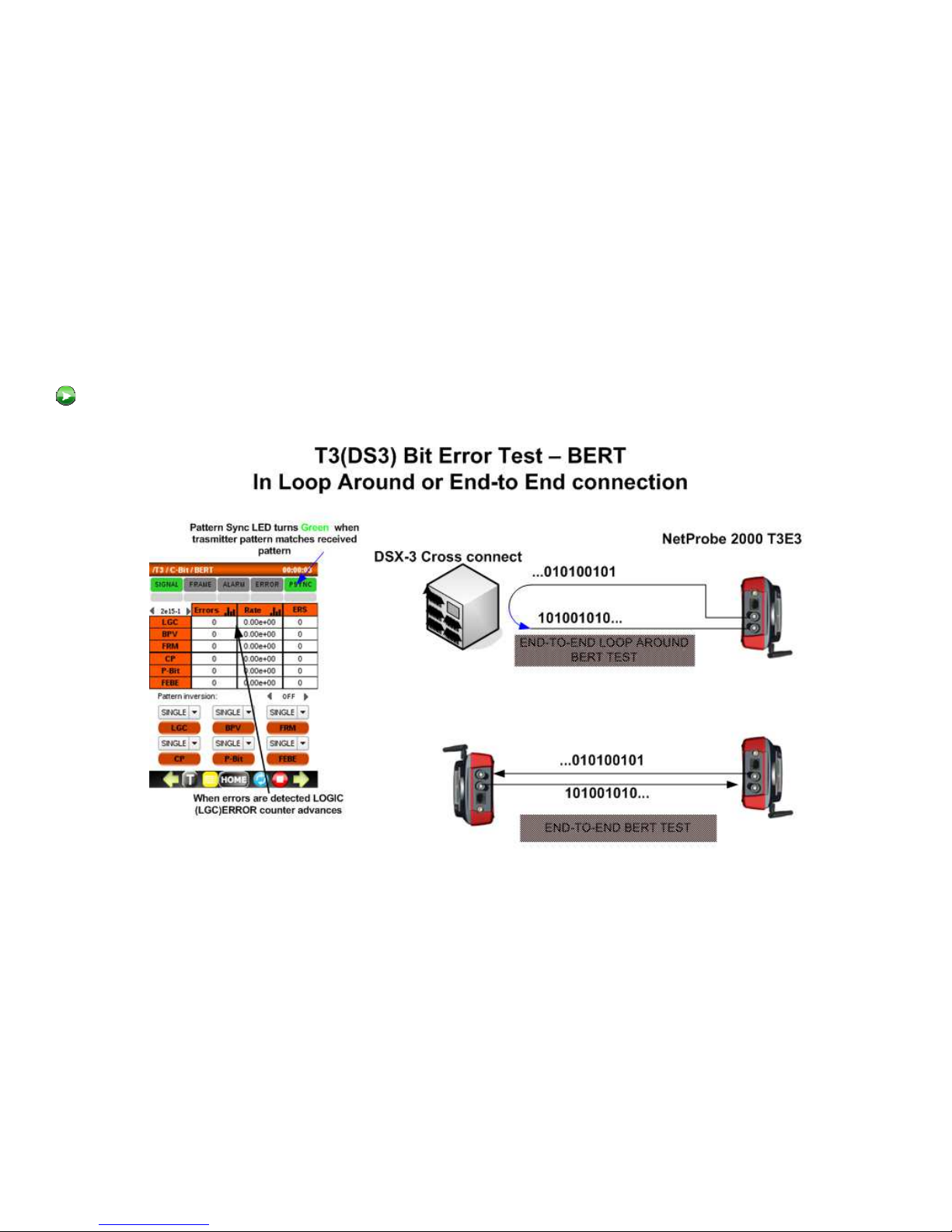
97
A typical loop around or point-to-point Bit Error Test setup is shown below. After the COAX connection is made, press
button.
Page 98
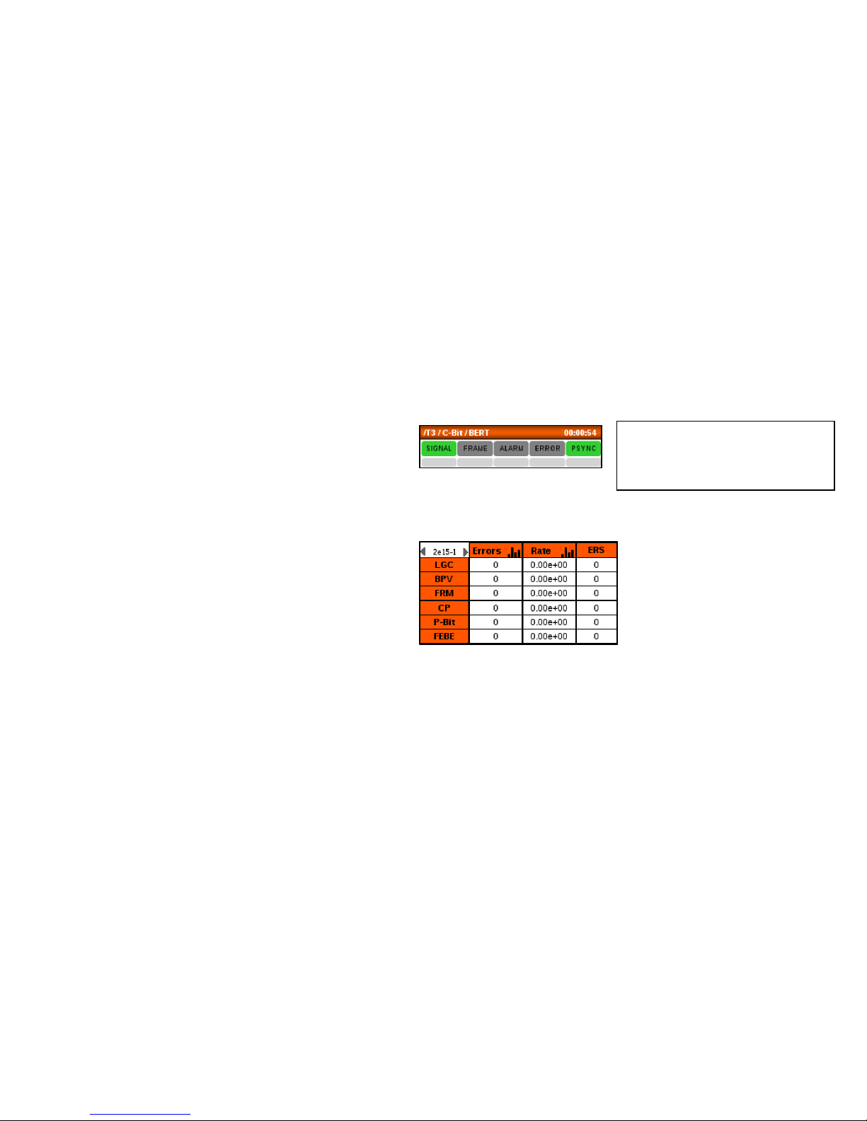
98
Check the BERT main screen and observe the following:
Tip:
Click on any history indicator box
to reset all history indicators.
• The real-time SIGNAL, PSYNC and FRAME
(with Framed data) indicators at the top of
the screen are Green. Red indicates a
problem. If these indicators are red, should
check all circuit connections and T3 setup.
• The history indicators below are gray. Red
indicates a problem. If an event
(SIGNAL/FRAME/ALARM/ERRROR/PSYNC)
occurs, the corresponding gray history area
will remain red until it is reset.
• Error counters report 0 or at least are not
quickly incrementing. If these are quickly
incrementing, check all circuit connections
and T3 setup.
Page 99
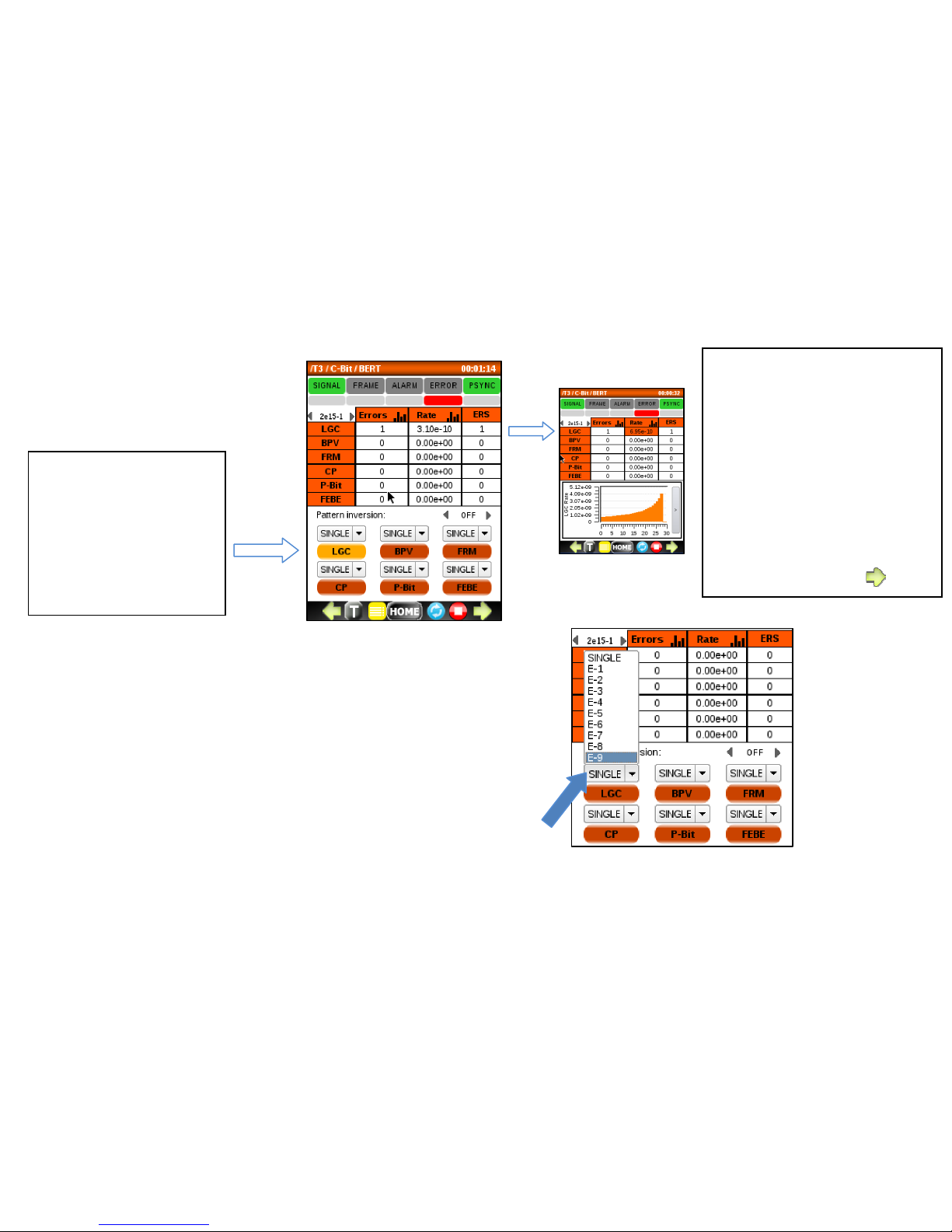
99
Optionally, a constant bit error rate can be injected using the RATE menu.
Select a rate from the pull down menu and press the corresponding
green button to begin the error RATE injection.
Tip:
Click in the Errors or Rate
columns to display a histogram
for the corresponding metric.
Click on the thin gray bar to
hide it.
Green arrows at the bottom
can be used to display
additional metrics, alarms and
timeslot information.
Tip:
To verify that everything
is setup properly after
starting BERT, click on
the LGC button to force
and detect a single bit
error.
Page 100
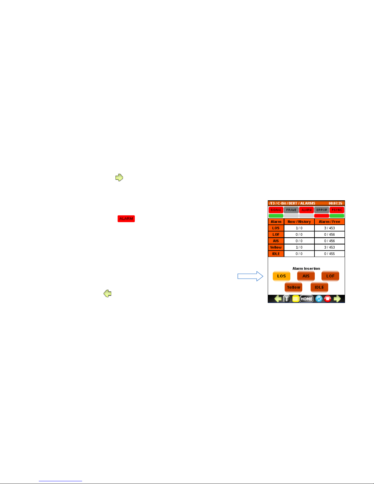
100
7.3.1 ALARM menu
To access the Alarms menu, press from the main BERT screen.
Use this menu to:
• Monitor the current and history alarm status to determine which
alarms caused the LED to turn red.
• Force an alarm condition onto the T3 line by pressing an Alarm
Insertion button. Caution: The alarm insertion will be continuous until
pressed again.
o LOS (Loss of Signal)
o LOF (Loss of Frame)
o AIS (All 1’s Alarm Indicator Signal)
o Yellow
o Idle
• To exit, press .
 Loading...