


User manual
4ch AHD SD
Mobile DVR
USER MANUAL
Version 1.0
User manual
No
Name
Quantit
y
Unit
Device Type
Basic
Basic+WIFI
Remark
1
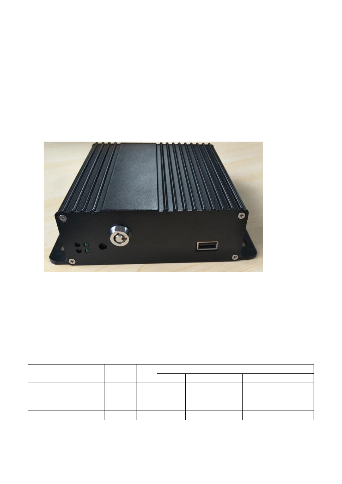
MDVR
1
set ✔ ✔
2
Remote Control
1
pcs ✔ ✔
Optional
3
Keys
2
pcs ✔ ✔
4
WIFI antenna
1
pcs ✘ ✔
Introduction
The manual is about the features and specifications of one kind of car DVR, it is an
integration of “4 monitoring and recording “, “Million Pixels Digital&Analog mixed car DVR”,
“wireless data transmission “.
In the manual it describes the functions and considerations of the modules ,the connector
signal definitions in the back panel, the interface definition and user’s operations.More
details,please check following directory.
State:
This manual may exist any technical describe inaccurate or misprint,also the contents will be
update unscheduled without notice,new contents will be added in next version;
We’re subject to improve or update product description or program,if any difference,all depend on
real goods,please understand.
1 Parts list

User manual
2 Product introduction
2.1 Product features
H.264 Compression Mode, Support 4CH real-time 1080P Million Pixels AHD input and Analog
Standard Definition camera input, or 2CH HD input + 2CH SD input; Exclusive pre-allocate DVR
Special File System Technology,Solving repeatedly wipe cause file fragmentation, solving SD card file
system collapse, data loss and cannot find SD card and file garbled, ensure the integrity of the data.
8-33V Adaptive Wide Voltage input, Super Low Power Consumption Design; SD card storage
(maximum support two pieces 128GB SD card. ) It can be completely resist car Vibration,Dust and
others cause data corruption; Support GPS/BD/G-SENSOR ; High Reliability Aviation plugs,High Cost
Performance with reliable stability,simple and clear operation menu .
HIS Solution,H.264 Compression Mode, Many stream recording,4CH Video+2CH Audio Input,
Compatible with 4CH 1080P/720P Mega Pixels Analog High Definition Camera input /2CH AHD
High Definition + 2CH Standard Definition mixed input / 4CH Analog Standard Definition Camera
input.
Real-time HD Video Recording, 1080P/D1/HD1/CIF for Optional,Adjustable Frame Rate Quality.
Professional Power Design for all kinds of Vehicles, 8-36V DC; Wide Voltage,
Over-load,Over-voltage,Short Circuit,Reverse Protection,Suitable for all kinds of vehicles.
Support DC 12V/2.5Amp output, it can offer power for cameras,mini monitor and some peripheral device.
SD card Data record storage (maximum support 128GB SD card. ) It can be completely resist car
Vibration,Dust and others cause data corruption;
Watchdog Abnormal will trigger Restart Protection Function . It can better protect Device and Video.
Exclusive pre-allocate DVR Special File System Technology,Solving repeatedly wipe cause file
fragmentation, and ensure the integrity of the data.
By accidents power-off protection function.Unique UPS Technology ensures the integrality of record
when power failure occurs,even can for 10-15s.
Flame out Time-lapse Video Recording Function ( Highest support long delay time 24 hours.)
Auto Recording,Time Recording,Alarming Recording Modes for Different Request.
Display vehicle traffic status, Vehicle numbers ,Route, Super-low speed vehicle Information, Convenient
management..
Support WIFI connection
All Aviation plugs, Super stable, High Anti-shock,Easy installation Plug in and out.
Unique WINDOWS 8 interface, Easily Smart GUI Interface, Fluent system interface is intuitive and
perfect.
Support SD card Remote Software Upgrade/OTA remote upgrade automatically, partition backup
technology upgrade don't crash.
Can be batch functional customization according to customer's requirements;
User manual
Main
Sub-Item
Instructions
Recording
Sub-System
Video Channel
4Channel video + 4Channel Audio recording synchronously;
Resolution
Support 4*1080P(1280*1080),4*D1(704*576),4*HD1(704*288), 4*CIF
(352*288);Each channel is individually adjustable.
Image Quality
0-7 levels, 0 is the highest level.
OSD
Overlays information such as date time and vehicle ID
Loop Rec
Support SD card loop recording, loop cover previous video
Record Mode
Timed recording, alarm trigger recording and manual recording
Preview
Support 1 channel and 4 channels preview. Support enlarge
video image when alarm trigger and video rear view trigger;
Disk
overwritten
Space pre-allocated Support disks overwritten function.
Playback
System
Video Search
Search video files anytime per day, type(n/a)
Playback
Support 1 to 4 channels playback.
Support forward and backward play at the speed of: x2 ,x4,x8,x16.
Support alarm spot search and time search.
GUI
Graphical User
Interface
Setup system parameters with the remote control.
Optional
Network
Can expand WIFI module,support 801.2b/g/n, 801.2a/c
Others
ON/OFF
System delay-time power on/off;
File System
DVR special file recording System Technology,Exclusive car record file
system,space pre-allocate,4ch single file Record,cyclic covering;To avoid the
storage of the media causes file fragments, with high reliability and high stability;
Item
Parameter
OS
Linux
Language
Chinese/English/Others (can be customized)
Video Compression
H.264 Compression Mode
OSD
Overlays information such as date time and vehicle ID
GUI
Graphical User
Interface
Can connect to external LED screen. Setup system parameters with the remote
control.
Video
Record
System
Video Input
4CH 1080P AHD/ 4CH standard definition /2CH high definition+2CH standard
definition mixed video input ,aviation plug.
Video Output
1CH CVBS
2.2 Main Functions
2.3 Parameter Sheet

User manual
Preview
Support 1 channel and 4 channels preview.,Support Manual/Alarm Trigger full
screen preview
Resolution
1080P/D1/HD1/CIF, MAX:4 channels of 1080P
Video Quality
0-7 levels, 0 is the highest level, 7 is the lowest level.
Video Standard
PAL: 100f/s , CCIR625 line,50field;
NTSC: 120f/s, CCIR525 line,60field;
CIF: 256Kbps ~ 1.5Mbps, multi levels video quality optional;
HD1: 600Kbps ~ 2.5Mbps, multi levels video quality optional;
D1: 800Kbps ~ 3Mbps, multi levels video quality optional;
720P : 1Mbps~4Mbps, multi levels video quality optional;
1080P: multi levels video quality optional;
Record Mode
The default setting is auto recording after power on. Timed recording, alarm
trigger recording and manual recording are supported.
Audio
Audio Input
4CH ,Aviation Plug
Compression
G.726 compression, 8KB/s speed
Wireless transfer
Support Built-in/External WIFI
G-Sensor
Support G-sensor(Optonal)
Video
Storage
Storage
1pieces SD Card,each max 128GB SD Card,
Upgrade
Support USB flash disk updating,SD card upgrade , OTA remote upgrade
automatically
File Format
H.264 General video format
USB
Front panel supports USB port, support USB flash disk upgrade to backup; hard
disk box USB port, can back up video data
Video
Playback
Video Search
Search video by Record Time/Record Type etc
Playback
Max support 4CH Replay /Stop/Fast Forward/Fast Reverse at same time
Support x 2,x4,x8,x16. fast forward or fast backward play
Safety Management
User/Admin 2 Levels Different Passwords , support screen lock
Voltage &
Power
Consumpti
on
Power
Management
Adaptive wide power input, support Wide Voltage, Over-load、Over-voltage、
Short Circuit、Reverse Protection..Support Time Setting/Delay power off
Voltage Input
DC:+10V ~ +33V
Voltage Output
+12V@2A
Power-off
Protection
UPS Technology,All video information can be saved automatically when the
power is cut off, and make sure that all the files can not be damaged.
Power
Consumption
Normal Working <5W Stand-by Status <0.5W
Working
Environme
nt
Temperature
-20℃ to +70℃
Humidity
20% to 80%
***** Above parameters any changes,please refer to actual product *****
User manual
Item
Name
Silk screen
Functional Specification
○
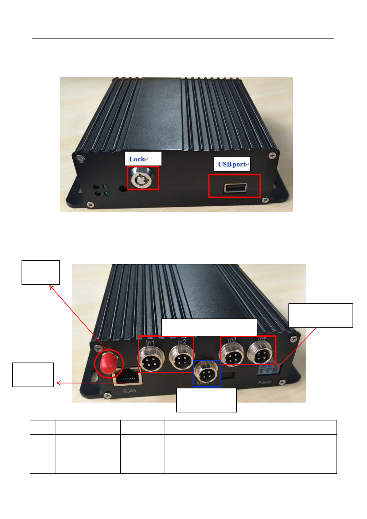
1
Video&Audio
Input interface
IN1-IN 4
1-4Channels, with DC 12V output,
○
2
Power Input
interface
POWER
Input Voltage DC 8-33V,
1 Video input:ch1 to ch4
○
Video output
○
WIFI
○
○
2.4 Front Panel
** Status LED will alternate loop flash when device power on, it will quick loop flash when device is upgrading **
2.5 4CH MDVR Back Panel
3
5 RJ45
4
2 Power input
4CH MDVR Back Panel items introduction:
User manual
○
3
WIFI Antenna Port
WIFI
○
4
Video&Audio
Output interface
AV OUT
Video&Audio output interface, with DC 12V output
○
5
RJ45
RJ45
It’s used for connecting network cables
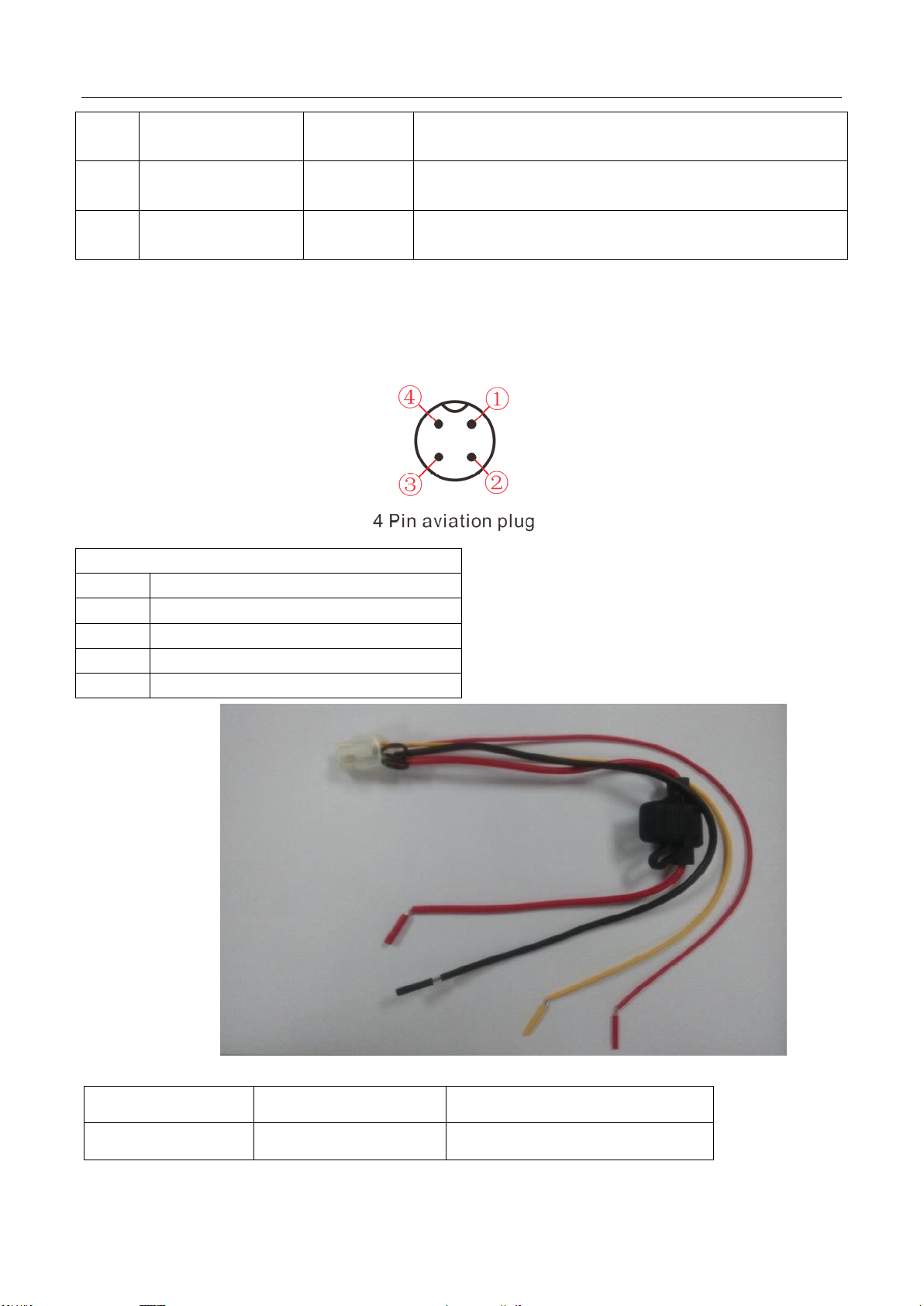
4 Pin aviation plug
PIN
FUNCTION
1
+12V
2
GND
3
Audio Input/output
4
Video Input/output
Color Line
Name
Description
Red
DC+
Power-Positive
The 4CH MDVR support channel AV1~ AV4, it’s Video&Audio Input interface use 4 Pin aviation plug,
PIN DESCRIPTION
Power cable pin definitions

User manual
Black
DC-
GND
Yellow
ACC
ACC
Red
12V-OUT
12V output
Wiring: red and black wire are connected directly to the car battery. Red wire to positive, black
to negative. Yellow line contacts FireWire, ignition switch mode is set to mode. The DVR device
turns on when the vehicle power on,DVR turn off automatically the vehicle power off. Yellow
line connected to the car keys to open the position (that is, before the automobile starter motor
gear) all the dashboard lights.
Note: 1) Before connecting wires,one need to make sure the battery voltage is between 6V ~
36VUU, otherwise it will be burned;
2) After connecting the cable, pay attention to insulation of the line between lines to
prevent short circuit and burned out the battery;
3) yellow line must be connected to the firing line, otherwise the device will not
support the ignition switch;
4) Special Note: 12V-OUT line can not be connected to the power input by mistake,
which can not be connected to ground by mistake;
5) Note: DVR installation must be connected to battery positive and negative
directly, can not be done with ground grounding, grounding will produce negative glitch host
running. Positive and negative power supply line diameter must be Φ1.5 above.

User manual
2.6 Remote Control
System Key
【 】: Turn on/ off key
【Info】: Info. Key (retain)
【 】:Lock. Press this key to lock remote input after exiting menu.
【 】: Switch 1~4 screens. Number keys 1~4 can do this too.

User manual
【Del】:Delete key.
【Number/Letter】Input key, you can input the number value to select a single channel preview.
Menu-key Function Description
【MENU】Start/Login/Exit menu
【EXIT】Back to the previous menu
【 】 Last program
【 】Next program
【 】Modify the current item/last subproject
【 】Modify the current item/next subproject
【OK】Confirm
Play Keys
【 】:Play/Pause
【 】: Stop
【 】:Fast forward. 1/2/4/8/60
【 】: Rewind. 1/2/4/8/60
【 】:Frame forward

User manual
3 Device Installation
3.1 Power Cable Connection
This MDVR use DC power supply, Wide operating range 10 to 33V
★ Use ignition switch to control video record delay time working
Red wire connect positive of the car battery, black wire connect negative,while yellow wire connect
independent ignition switch or independent positive.
★ Do not use ignition switch to control video record delay time working(Office Test also using
this mode)
The red and yellow wire connect together to connect the battery positive,Black wire to connect the
battery negative .
Attention
1. The recorder is DC power supply; please attention the positive and negative polar.
2. The voltage is 8V~36V.Do not insert voltage that beyond this range. Under low voltage the recorder
doesn’t work, under high voltage will be harm to the recorder.
3. Please make sure the recorder is connect with the car power directly. Do not connect with the generator,
the instantaneous voltage will harm to the recorder.
4. The initial power will beyond 30W when the DVR connect with the Camera (the consumed power is
different due to the connect with different device), the power supply must beyond 30W.
5. The power cables must can stand beyond 60W.(For example, when the output voltage of car is 12V,the
power cables must can bear 5A or more).
6. Please put the cover on the cables, the cover must be wear-resistant, heat-resistant, water-proof,
grease-proof, in case of short circuit and open circuit.
7. Please install a 10A fuse box near the battery output positive polar for fear of the short circuit will
damage the power supply.
4 Operation Interface Setup
4.1 User Loading
When the password switch is set to “Off”: The host start and press [OK] key, will direct access to the
main menu..
When the password switch is set to “On”: Move the cursor to “landing” column, Press [OK] key, then
can enter the main menu.

User manual
**********************************************************************************
The administrator default password is 111111(or device number –before changed the password available);
User default password is 000000, only have query permissions;
**********************************************************************************
4.2 System Main Menu
The main menu includes: Search, System setup, Rec setup, Network setup, Alarm setup and Peripheral,
System Information, as below:
4.3 Search
Query menu includes: Record, Log and Picture,

User manual
2.1.1 Video Search
**** Green color display indicates current day and time exist video file ****
“Search Date”: Press the number key to enter date, default is current date.
“Start Time”: Press the number key to enter date, default is 00:00.
“End Time”: Press the number key to enter date, default is 23:59.
“Record Type”: Press the [OK] button to select the query type: All videos \Alarm recording. Default is
All videos.
“Storage Media”: Press the [OK] button to select: all disks, disk 1, disk 2.
“Search”:Move the cursor to “Search” button, press the [OK] key to enter the search results interface.

User manual
Press the arrow keys to select the video you want, press the keys to quickly flip, press
to turn to first page or last page, press the play button to play the video, press [ESC] key to return to
the previous menu。
Press the arrow keys to select “Home”, “Previous”, “Next”, “Last” and press [OK] button to display the
next page information.
2.1.2 Log Query
This menu is to query device operation and working log , you can choose the same type log via log
categories.
When select a single log, press the keys to quickly flip over, and press to turn to first page
or last page.
2.1.3 Picture Search
This menu is mainly for searching the screenshot pictures.

User manual
Zoom up single full screen will auto screen capture by default , it will be triggered by the alarm linkage
or manually operate.
**** Pictures and device log all save in the second partition ****
4.4 System Setup
Under System Setup menu includes: Power, time setup, user setup, terminal setup (menu setup and
modifying need to choose save to take effect)

User manual
2.4.1 Terminal Setup
By remote control input settings: device number, phone number, license plate number, the provincial
domain ID, the City ID, terminal type, manufacturer ID, terminal ID, the device management (data in
accordance with the Department of standards, Chinese input can use the soft keyboard input)
2.4.2 User Management
“Password Enable”: You can enable or disable password authentication to access the menu.
Modify or setup password of users and the administrator by remote control.
**** ADMIN Pass : 111111, USER Pass : 000000 ****
2.4.3 Time Set
This menu is to setup device parameters, such as date and time, etc.

User manual
“Date Type”: Different date format for choosing.
“Date”: Press the number keys to enter current date.
“Time Synchronization”: calibration mode: GPS, NTP and other school models available.
“Time Zone”: Setup the time zone of the location of the device
“Timeout”: optional remote control does not operate the exit time
“Real Time”: Press the number key to enter the current time
2.4.4 Power Management
This menu is to setup Power management modes and power distribution.
“Power mode”:press the number keys to select the type, the default is ignition mode.
“Delay Off”: Press the number keys to enter the time, the default is 5 minutes, can be set to 1440 minutes
“Screen time”: Press the number keys to enter the time, the default is 60 minutes, can be set to 0-1440
minutes
“Power On”: Press the number key to enter time, setup the timer start time
“Power Off”: Press the number key to enter time, setup the timer off time

User manual
2.4.5 Parameters Management
“Import”:Import parameters from HDD or SD Card to current device.Import the system configuration
parameters which has set up and restore the factory settings to the factory states
“Export”:Export current device parameters to HDD or SD Card;
“Default”:Default to factory setting; This operation will clear all the setting on the device.
If quantity Devices with same setting,please using Parameter Export/Import for configuration, after
setting one device, export these parameters to U-Disk or SD Card then import to other rest devices to be fast
setting.
2.4.6 FORMAT
Format Disk choice, device will reboot disk after confirming, log and pictures and other related info will
be reserved.
Attention:
Device will format automatically when it starts, new SD card, can be formatted on the computer, in
general, it doesn’t need format disk in DVR by manual.

User manual
2.5. REC Setup
Recording setup menu includes: basic setup, Main stream, Sub stream, time recording, Storage
management(configuration and modification must select Save to take effect)
2.5.1 Basic Setup
This menu is to setup the basic video, audio and video parameters and can change into standard
definition, AHD high definition and mixed mode.
“Video Type”: PAL / NTSC, press [OK] key to select.
“Record Mode”: Auto / timer / alarm recording, press [OK] key to select.
“Camera Type “: Can switch the status of standard definition , high definition or mixed camera input.
“Resolution”:Set the resolution of VGA output.
“ Layout”: optional: Single, 2-channel, 4 grids, nine grids and other video channel layout.
“Packket time”:The time of a single record file.

User manual
Attention :
If the camera type and DVR setting mode(AHD HD/Analog/Mixture) don’t match, then it will show
“video lost”, In Mixture mode, 1,2CHANNEL is AHD high definition input, 3,4CHANNEL is analog
standard definition input;
2.5.2 Main Stream
This manual is to setup the code stream and definition of video channel.
“Enable”: open or close the channel of pre-recording function, press [OK] key to select.
“Resolution”: CIF, HD1, D1 and 1080P resolution for choosing, press [OK] key to select.
“FPS”: 1-25 frame (P standard), 1-30 frame (N standard) channel recording frame rate for choosing.
“Image quality” setup video quality under different resolution, 4-speed adjustable.
“Audio” setup the audio recording on or off.
****************************************************************************************
According to the storage space and quality requirements, the resolution of each channel and stream can
be configured individually
****************************************************************************************
2.5.3 Sub-stream
This menu is used to set the parameters of the transmission stream.

User manual
“Resolution” Setup the transmission resolution, press [OK] key to enter.
“FPS” Setup the transmission time frames, press [OK] key to enter.
“Image quality” setup transmission quality grade, press [OK] key to enter.
****************************************************************************************
Sub-stream is the code stream which device upload via 3G/4G, high definition main code stream can be chose
in the client-side platform
****************************************************************************************
2.5.4 Time Record Setup
Setup the timer recording time periods, everyday can be set to two periods.
Move the cursor to “Timing Recording” and press [OK] button to set up the following timing list.
****************************************************************************************
Timer recording start time is before the end time.
****************************************************************************************

User manual
2.5.5 Storage management
“pre-recorded”: pre-recorded alarm recording time of 0-60 seconds to setup, press number keys to setup.
“Alarm delay”: alarm delay recording time, 120-3600 seconds to set up, press number keys to setup.
“Alarm Fime”: The storage time of alarm file, 3-45 days to set up, press number keys to setup.
2.6. Network Set
Including: Center setup,Local Network , dialing setup,WIFI setup.
2.6.1 Center Setup
Set Server IP and Port ;

User manual
“Monitoring Center”:Set 3G /4G Video Center IP or domain,port information etc,
“Network Type”:Set 3G network type, IP address/Domain optional;
“Center IP”:3G Server IP/Domain setup. Press right key to enter keyboard interface,input the numbers
via remote controller,then press [OK] for setting,;
“Port”:Communication port between 3G device and Server,must be same with server configuration;
Remind:
In “ Info “ interface, W connected : it means device connected server already; B connected : it means
device connected ministerial standard platform already, Connected : it means two platforms both connected
device successfully.
2.6.2 Local Network Setup
Device Local Network setup
“IP”\”Mask”\”Gateway”\ “DNS1” \”DNS2”\”MAC”:IP,Mask,Gateway,MAC setting for LAN network
testing.
Attention:

User manual
When net cable directly connect to the device, only can use 4PIN definition net cable (please see more
definition in the addenda), otherwise it will lead device dead.
2.6.3 WIFI Setup
“WIFI-EN”:WIFI On/Off Setting,Press [OK] for choosing;
“Encr-EN”: WIFI encryption ON/Off Setting,press [OK] for choosing;
“Au-Mode”: WIFI Authentication mode setting,Please choose same one with your router,
“Enc-Type”: WIFI Encryption type setting,Please choose the one same with your router,
“IP”\”Mask”\”Gateway”:WIFI IP/Mask/Gateway setting
“SSID”: Input Your WIFI SSID,
“PWD”: Same with your WIFI password,
****************************************************************************************
According to the specific configuration of WIFI network environment, please pay attention to check the
accuracy of the characters and the IP address.
IP address set by WIFI and local network can not be in the same network segment.
****************************************************************************************
2.7. System Info
System Info have 2 parts for detail information;can view by menu or Press INFO.

User manual

20C
 Loading...