

Page 1

1. [Docs] NetPing 8/PWR-220 v3/SMS . . . . . . . . . . . . . . . . . . . . . . . . . . . . . . . . . . . . . . . . . . . . . . . . . . . . . . . . . . . . . . . . . . . . . . . . . . . . . 3
1.1 [ENG] Netping 8/PWR-220 v3/SMS, User guide . . . . . . . . . . . . . . . . . . . . . . . . . . . . . . . . . . . . . . . . . . . . . . . . . . . . . . . . . . . . . . 4
1.1.1 [8PWR] Copyright and Disclaimer . . . . . . . . . . . . . . . . . . . . . . . . . . . . . . . . . . . . . . . . . . . . . . . . . . . . . . . . . . . . . . . . . . . . 5
1.1.2 [8PWR] Introduction . . . . . . . . . . . . . . . . . . . . . . . . . . . . . . . . . . . . . . . . . . . . . . . . . . . . . . . . . . . . . . . . . . . . . . . . . . . . . . . 6
1.1.3 [8PWR] Device Overview . . . . . . . . . . . . . . . . . . . . . . . . . . . . . . . . . . . . . . . . . . . . . . . . . . . . . . . . . . . . . . . . . . . . . . . . . . . . 7
1.1.4 [8PWR] Sockets and Indication Elements . . . . . . . . . . . . . . . . . . . . . . . . . . . . . . . . . . . . . . . . . . . . . . . . . . . . . . . . . . . . . . . 8
1.1.5 [8PWR] Power Supply Channels Management . . . . . . . . . . . . . . . . . . . . . . . . . . . . . . . . . . . . . . . . . . . . . . . . . . . . . . . . . . . 12
1.1.6 [8PWR] Sensors Plugin . . . . . . . . . . . . . . . . . . . . . . . . . . . . . . . . . . . . . . . . . . . . . . . . . . . . . . . . . . . . . . . . . . . . . . . . . . . . . 13
1.1.7 [8PWR] Setting Parameters to Default Values (to the Factory Settings) . . . . . . . . . . . . . . . . . . . . . . . . . . . . . . . . . . . . . . . 16
1.1.8 [8PWR] Using IO Lines for External Devices Management (in an Output Mode) . . . . . . . . . . . . . . . . . . . . . . . . . . . . . . . 17
1.1.9 [8PWR] Shipping Kit . . . . . . . . . . . . . . . . . . . . . . . . . . . . . . . . . . . . . . . . . . . . . . . . . . . . . . . . . . . . . . . . . . . . . . . . . . . . . . . 18
1.1.10 [8PWR] Operating and Storage Conditions . . . . . . . . . . . . . . . . . . . . . . . . . . . . . . . . . . . . . . . . . . . . . . . . . . . . . . . . . . . . 19
1.1.11 [8PWR] Warranty . . . . . . . . . . . . . . . . . . . . . . . . . . . . . . . . . . . . . . . . . . . . . . . . . . . . . . . . . . . . . . . . . . . . . . . . . . . . . . . . 20
1.2 [ENG] NetPing 8/PWR-220 v3/SMS, Firmware description . . . . . . . . . . . . . . . . . . . . . . . . . . . . . . . . . . . . . . . . . . . . . . . . . . . . . 21
1.2.1 [ENG] 1. [DKSF 48.4 IU] Introduction . . . . . . . . . . . . . . . . . . . . . . . . . . . . . . . . . . . . . . . . . . . . . . . . . . . . . . . . . . . . . . . . 22
1.2.2 [ENG] 2. [DKSF 48.4 IU] Receiving a Main Information about a Device . . . . . . . . . . . . . . . . . . . . . . . . . . . . . . . . . . . . . 23
1.2.2.1 [ENG] 2.1. [DKSF 48.4 IU] Default Username and Password . . . . . . . . . . . . . . . . . . . . . . . . . . . . . . . . . . . . . . . . . 24
1.2.2.2 [ENG] 2.2. [DKSF 48.4 IU] How to Know a Default IP Address and MAC Address of a Device? . . . . . . . . . . . . 25
1.2.2.3 [ENG] 2.3. [DKSF 48.4 IU] Connecting a Device with a Default Authorization to a Web Interface . . . . . . . . . . . 26
1.2.2.4 [ENG] 2.4. [DKSF 48.4 IU] I Need to Know a Firmware Version, a Hardware Version, a Serial Number, a Model of
a Device and Its Uptime . . . . . . . . . . . . . . . . . . . . . . . . . . . . . . . . . . . . . . . . . . . . . . . . . . . . . . . . . . . . . . . . . . . . . . . . . . . . . 27
1.2.2.5 [ENG] 2.5. [DKSF 48.4 IU] Where Can I See a Name, a Location and Contacts of a Device? . . . . . . . . . . . . . . . . 28
1.2.2.6 [ENG] 2.6. [DKSF 48.4 IU] How to Reboot a Device? . . . . . . . . . . . . . . . . . . . . . . . . . . . . . . . . . . . . . . . . . . . . . . . 29
1.2.3 [ENG] 3. [DKSF 48.4 IU] Basic Configuration . . . . . . . . . . . . . . . . . . . . . . . . . . . . . . . . . . . . . . . . . . . . . . . . . . . . . . . . . . 30
1.2.3.1 [ENG] 3.1. [DKSF 48.4 IU] How to Configure Name of a Device, Its Location and Contacts? . . . . . . . . . . . . . . . 31
1.2.3.2 [ENG] 3.2. [DKSF 48.4 IU] Where to Change Settings of a Network Interface? . . . . . . . . . . . . . . . . . . . . . . . . . . . 32
1.2.3.3 [ENG] 3.3. [DKSF 48.4 IU] Changing a Username and a Password . . . . . . . . . . . . . . . . . . . . . . . . . . . . . . . . . . . . . 33
1.2.3.4 [ENG] 3.4. [DKSF 48.4 IU] How to Set Community for SNMP? . . . . . . . . . . . . . . . . . . . . . . . . . . . . . . . . . . . . . . . 34
1.2.3.5 [ENG] 3.5. [DKSF 48.4 IU] How to Restrict Access to a Device? . . . . . . . . . . . . . . . . . . . . . . . . . . . . . . . . . . . . . . . 35
1.2.3.6 [ENG] 3.6. [DKSF 48.4 IU] How to Disable All Notifications Quickly? . . . . . . . . . . . . . . . . . . . . . . . . . . . . . . . . . 36
1.2.3.7 [ENG] 3.7. [DKSF 48.4 IU] It Is Necessary to Send SNMP Trap Notifications. How to Configure This? . . . . . . . 37
1.2.3.8 [ENG] 3.8. [DKSF 48.4 IU] How to Set the Clock? . . . . . . . . . . . . . . . . . . . . . . . . . . . . . . . . . . . . . . . . . . . . . . . . . . 38
1.2.3.9 [ENG] 3.9. [DKSF 48.4 IU] I Want to Configure SYSLOG. How to Do This? . . . . . . . . . . . . . . . . . . . . . . . . . . . . 39
1.2.3.10 [ENG] 3.10. [DKSF 48.4 IU] How to Receive Notifications and Reports via Email? . . . . . . . . . . . . . . . . . . . . . . 40
1.2.3.11 [ENG] 3.11. [DKSF 48.4 IU] How to Update Firmware on a Device? . . . . . . . . . . . . . . . . . . . . . . . . . . . . . . . . . . 41
1.2.3.12 [ENG] 3.12. [DKSF 48.4 IU] What Notifications Has the Log File Got? . . . . . . . . . . . . . . . . . . . . . . . . . . . . . . . . 42
1.2.4 [ENG] 4. [DKSF 48.4 IU] Working with Temperature Sensors . . . . . . . . . . . . . . . . . . . . . . . . . . . . . . . . . . . . . . . . . . . . . . 46
1.2.4.1 [ENG] 4.1. [DKSF 48.4 IU] What Temperature Sensors a Device Supports? . . . . . . . . . . . . . . . . . . . . . . . . . . . . . . 47
1.2.4.2 [ENG] 4.2. [DKSF 48.4 IU] How to Determine a Unique Number of a 1-Wire Sensor? . . . . . . . . . . . . . . . . . . . . . 48
1.2.4.3 [ENG] 4.3. [DKSF 48.4 IU] Where to Read a Current Temperature? . . . . . . . . . . . . . . . . . . . . . . . . . . . . . . . . . . . . 49
1.2.4.4 [ENG] 4.4. [DKSF 48.4 IU] Is It Possible to Set a Description for Temperature Sensors? . . . . . . . . . . . . . . . . . . . 50
1.2.4.5 [ENG] 4.5. [DKSF 48.4 IU] Configuring Top and Bottom Margin of a Safe Range for a Temperature Sensor . . . 51
1.2.4.6 [ENG] 4.6. [DKSF 48.4 IU] I Want to Configure Sending Notifications When a Status of a Temperature Sensor Is
Changed. How to Do This? . . . . . . . . . . . . . . . . . . . . . . . . . . . . . . . . . . . . . . . . . . . . . . . . . . . . . . . . . . . . . . . . . . . . . . . . . . . 52
1.2.5 [ENG] 5. [DKSF 48.4 IU] Working with a Humidity Sensor . . . . . . . . . . . . . . . . . . . . . . . . . . . . . . . . . . . . . . . . . . . . . . . . 53
1.2.5.1 [ENG] 5.1. [DKSF 48.4 IU] What Humidity Sensor a Device Supports? . . . . . . . . . . . . . . . . . . . . . . . . . . . . . . . . . 54
1.2.5.2 [ENG] 5.2. [DKSF 48.4 IU] How to Determine a Unique Id of a 1-Wire Humidity Sensor? . . . . . . . . . . . . . . . . . . 55
1.2.5.3 [ENG] 5.3. [DKSF 48.4 IU] Initial Configuration of a Humidity Sensor . . . . . . . . . . . . . . . . . . . . . . . . . . . . . . . . . 56
1.2.5.4 [ENG] 5.4. [DKSF 48.4 IU] Browsing Readings and Configuring Parameters of a Humidity Sensor in a Web
Interface . . . . . . . . . . . . . . . . . . . . . . . . . . . . . . . . . . . . . . . . . . . . . . . . . . . . . . . . . . . . . . . . . . . . . . . . . . . . . . . . . . . . . . . . . . 57
1.2.5.5 [ENG] 5.5. [DKSF 48.4 IU] I Want to Configure Sending Notifications When a Humidity Sensor Status Is Changed.
How to Do This? . . . . . . . . . . . . . . . . . . . . . . . . . . . . . . . . . . . . . . . . . . . . . . . . . . . . . . . . . . . . . . . . . . . . . . . . . . . . . . . . . . . 58
1.2.6 [ENG] 6. [DKSF 48.4 IU] Working with Smoke Sensors . . . . . . . . . . . . . . . . . . . . . . . . . . . . . . . . . . . . . . . . . . . . . . . . . . . 59
1.2.6.1 [ENG] 6.1. [DKSF 48.4 IU] What Smoke Sensors a Device Supports? . . . . . . . . . . . . . . . . . . . . . . . . . . . . . . . . . . . 60
1.2.6.2 [ENG] 6.2. [DKSF 48.4 IU] How to Determine a Unique Number of a 1-Wire Smoke Sensor? . . . . . . . . . . . . . . . 61
1.2.6.3 [ENG] 6.3. [DKSF 48.4 IU] Initial Configuring of Smoke Sensors . . . . . . . . . . . . . . . . . . . . . . . . . . . . . . . . . . . . . . 62
1.2.6.4 [ENG] 6.4. [DKSF 48.4 IU] Is It Possible to Set Description for Smoke Sensors? . . . . . . . . . . . . . . . . . . . . . . . . . . 63
1.2.6.5 [ENG] 6.5. [DKSF 48.4 IU] How to Browse a Current Status of Smoke Sensors? . . . . . . . . . . . . . . . . . . . . . . . . . . 64
1.2.6.6 [ENG] 6.6. [DKSF 48.4 IU] How to Turn a Power Off and Reset a Smoke Sensor? . . . . . . . . . . . . . . . . . . . . . . . . 65
1.2.6.7 [ENG] 6.7. [DKSF 48.4 IU] I Want to Configure Sending Notifications When a Sensor Status Is Changed. How to
Do This? . . . . . . . . . . . . . . . . . . . . . . . . . . . . . . . . . . . . . . . . . . . . . . . . . . . . . . . . . . . . . . . . . . . . . . . . . . . . . . . . . . . . . . . . . . 66
1.2.7 [ENG] 7. [DKSF 48.4 IU] Working with Discrete Input-Output Channels . . . . . . . . . . . . . . . . . . . . . . . . . . . . . . . . . . . . 67
1.2.7.1 [ENG] 7.1. [DKSF 48.4 IU] Is It Possible to Set a Description for an Input-Output Line? . . . . . . . . . . . . . . . . . . . 68
1.2.7.2 [ENG] 7.2. [DKSF 48.4 IU] Configuring Operation Mode of an Input-Output Line . . . . . . . . . . . . . . . . . . . . . . . 69
1.2.7.3 [ENG] 7.3. [DKSF 48.4 IU] How to Define a Current Logic Level at an Input-Output Line? . . . . . . . . . . . . . . . . 70
1.2.7.4 [ENG] 7.4. [DKSF 48.4 IU] How to Manage an Input-Output Line in the Output Mode? . . . . . . . . . . . . . . . . . . . 71
1.2.7.5 [ENG] 7.5. [DKSF 48.4 IU] I Want to Configure Sending Notifications When Changing a Logic Level of an
Input-Output Line. How to Do This? . . . . . . . . . . . . . . . . . . . . . . . . . . . . . . . . . . . . . . . . . . . . . . . . . . . . . . . . . . . . . . . . . . . 72
1.2.7.6 [ENG] 7.6. [DKSF 48.4 IU] For What a Filter for Short Noises Is Necessary in Settings of an Input-Output Line? . 74
74
1.2.8 [ENG] 8. [DKSF 48.4 IU] Working with Built-In Relays . . . . . . . . . . . . . . . . . . . . . . . . . . . . . . . . . . . . . . . . . . . . . . . . . . 75
1.2.8.1 [ENG] 8.1 [DKSF 48.4 IU] Configuring Relay Management Modes . . . . . . . . . . . . . . . . . . . . . . . . . . . . . . . . . . . . 76
Page 2

1.2.8.2 [ENG] 8.2 [DKSF 48.4 IU] I Want to Configure Sending Notifications on Events of Relay Triggering. How to Do
This? . . . . . . . . . . . . . . . . . . . . . . . . . . . . . . . . . . . . . . . . . . . . . . . . . . . . . . . . . . . . . . . . . . . . . . . . . . . . . . . . . . . . . . . . . . . . . 77
1.2.8.3 [ENG] 8.3. [DKSF 48.4 IU] What Is «Watchdog», and How to Configure It? . . . . . . . . . . . . . . . . . . . . . . . . . . . . . 78
1.2.8.4 [ENG] 8.4. [DKSF 48.4 IU] What Is «Schedule», and How to Configure It? . . . . . . . . . . . . . . . . . . . . . . . . . . . . . . 80
1.2.9 [ENG] 9. [DKSF 48.4 IU] Working with Device Power Supply Inputs . . . . . . . . . . . . . . . . . . . . . . . . . . . . . . . . . . . . . . . . 82
1.2.9.1 [ENG] 9.1. [DKSF 48.4 IU] Configuring Power Supply Inputs in a Device Web Interface . . . . . . . . . . . . . . . . . . . 83
1.2.10 [ENG] 10. [DKSF 48.4 IU] Working with the Module «Logic» . . . . . . . . . . . . . . . . . . . . . . . . . . . . . . . . . . . . . . . . . . . . 84
1.2.10.1 [ENG] 10.1. [DKSF 48.4 IU] What Is «Logic»? . . . . . . . . . . . . . . . . . . . . . . . . . . . . . . . . . . . . . . . . . . . . . . . . . . . . 85
1.2.10.2 [ENG] 10.2. [DKSF 48.4 IU] How to Use the Module «Logic»? . . . . . . . . . . . . . . . . . . . . . . . . . . . . . . . . . . . . . . . 86
1.2.10.3 [ENG] 10.3. [DKSF 48.4 IU] Configuring Thermostat . . . . . . . . . . . . . . . . . . . . . . . . . . . . . . . . . . . . . . . . . . . . . . 89
1.2.10.4 [ENG] 10.4. [DKSF 48.4 IU] How to Configure Pinger in the Module «Logic»? . . . . . . . . . . . . . . . . . . . . . . . . . . 90
1.2.10.5 [ENG] 10.5. [DKSF 48.4 IU] What Is SNMP SETTER? . . . . . . . . . . . . . . . . . . . . . . . . . . . . . . . . . . . . . . . . . . . . . 91
1.2.10.6 [ENG] 10.6. [DKSF 48.4 IU] Reset Signal and Initial Statuses of Outputs . . . . . . . . . . . . . . . . . . . . . . . . . . . . . . . 92
1.2.10.7 [ENG] 10.7. [DKSF 48.4 IU] Connecting Relays and IO Lines . . . . . . . . . . . . . . . . . . . . . . . . . . . . . . . . . . . . . . . . 93
1.2.10.8 [ENG] 10.8. [DKSF 48.4 IU] IR Commands . . . . . . . . . . . . . . . . . . . . . . . . . . . . . . . . . . . . . . . . . . . . . . . . . . . . . . 94
1.2.10.9 [ENG] 10.9. [DKSF 48.4 IU] Examples of Configurations of the Module «Logic» . . . . . . . . . . . . . . . . . . . . . . . . 95
1.2.11 [ENG] 11. [DKSF 48.4 IU] Working with IR Control Module . . . . . . . . . . . . . . . . . . . . . . . . . . . . . . . . . . . . . . . . . . . . . 99
1.2.11.1 [ENG] 11.1. [DKSF 48.4 IU] How to Record IR Commands Properly? . . . . . . . . . . . . . . . . . . . . . . . . . . . . . . . . . 100
1.2.11.2 [ENG] 11.2. [DKSF 48.4 IU] Reproducing IR Commands through a Web Interface . . . . . . . . . . . . . . . . . . . . . . 101
1.2.11.3 [ENG] 11.3. [DKSF 48.4 IU] Is It Possible to Reproduce IR Commands through SNMP? . . . . . . . . . . . . . . . . . 102
1.2.11.4 [ENG] 11.4. [DKSF 48.4 IU] How to Determine a Firmware Version of an IR Module? . . . . . . . . . . . . . . . . . . . 103
1.2.11.5 [ENG] 11.5. [DKSF 48.4 IU] Recommendations . . . . . . . . . . . . . . . . . . . . . . . . . . . . . . . . . . . . . . . . . . . . . . . . . . . 104
1.2.12 [ENG] 12. [DKSF 48.4 IU] Working with SMS Notifications and an Embedded GSM Modem . . . . . . . . . . . . . . . . . . 105
1.2.12.1 [ENG] 12.1. [DKSF 48.4 IU] How to Know a Balance on a SIM Card? . . . . . . . . . . . . . . . . . . . . . . . . . . . . . . . . 106
1.2.12.2 [ENG] 12.2. [DKSF 48.4 IU] I Need to Specify a Number for Sending SMS Notifications. How to Do This? . . 107
1.2.12.3 [ENG] 12.3. [DKSF 48.4 IU] How to Enable Detailed Logging for a GSM Modem? . . . . . . . . . . . . . . . . . . . . . . 108
1.2.12.4 [ENG] 12.4. [DKSF 48.4 IU] Checking a GSM Signal Strength . . . . . . . . . . . . . . . . . . . . . . . . . . . . . . . . . . . . . . . 109
1.2.12.5 [ENG] 12.5. [DKSF 48.4 IU] Receiving an SMS Notification about Previously Specified Events . . . . . . . . . . . . 110
1.2.12.6 [ENG] 12.6. [DKSF 48.4 IU] GSM Modem Does not Work. How to Reboot It? . . . . . . . . . . . . . . . . . . . . . . . . . 111
1.2.12.7 [ENG] 12.7. [DKSF 48.4 IU] What SMS Notifications Can a Device Send? . . . . . . . . . . . . . . . . . . . . . . . . . . . . . 112
1.2.12.8 [ENG] 12.8. [DKSF 48.4 IU] How to Control a Device Using SMS Commands . . . . . . . . . . . . . . . . . . . . . . . . . . 116
1.2.12.9 [ENG] 12.9. [DKSF 48.4 IU] Adjusting Time of Sending a Daily Report about a Status of Sensors and IO Lines as
an SMS Notification . . . . . . . . . . . . . . . . . . . . . . . . . . . . . . . . . . . . . . . . . . . . . . . . . . . . . . . . . . . . . . . . . . . . . . . . . . . . . . . . 120
1.2.12.10 [ENG] 12.10. [DKSF 48.4 IU] How to Know IMEI of an Embedded GSM Modem? . . . . . . . . . . . . . . . . . . . . . 121
1.2.12.11 [ENG] 12.11. [DKSF 48.4 IU] How to Send Random SMS? . . . . . . . . . . . . . . . . . . . . . . . . . . . . . . . . . . . . . . . . . 122
1.2.13 [ENG] 13. [DKSF 48.4 IU] Device Supporting SNMP Protocol . . . . . . . . . . . . . . . . . . . . . . . . . . . . . . . . . . . . . . . . . . . . 125
1.2.13.1 [ENG] 13.1. [DKSF 48.4 IU] Device Supporting SNMP Protocol . . . . . . . . . . . . . . . . . . . . . . . . . . . . . . . . . . . . . 126
1.2.13.2 [ENG] 13.2. [DKSF 48.4 IU] Configuring Sending SNMP TRAP Notifications . . . . . . . . . . . . . . . . . . . . . . . . . . 127
1.2.13.3 [ENG] 13.3. [DKSF 48.4 IU] What OID Are Supported by a Device? . . . . . . . . . . . . . . . . . . . . . . . . . . . . . . . . . . 129
1.2.13.4 [ENG] 13.4. [DKSF 48.4 IU] Supporting SNMP trap . . . . . . . . . . . . . . . . . . . . . . . . . . . . . . . . . . . . . . . . . . . . . . . 133
1.2.14 [ENG] 14. [DKSF 48.4 IU] Support of URL-Encoded Commands by a Device . . . . . . . . . . . . . . . . . . . . . . . . . . . . . . . 136
1.2.14.1 [ENG] 14.1. [DKSF 48.4 IU] Controlling IO Lines . . . . . . . . . . . . . . . . . . . . . . . . . . . . . . . . . . . . . . . . . . . . . . . . . 137
1.2.14.2 [ENG] 14.2. [DKSF 48.4 IU] Relay Management . . . . . . . . . . . . . . . . . . . . . . . . . . . . . . . . . . . . . . . . . . . . . . . . . . 139
1.2.14.3 [ENG] 14.3. [DKSF 48.4 IU] Controlling Reserving Power Supply Inputs . . . . . . . . . . . . . . . . . . . . . . . . . . . . . . 141
1.2.14.4 [ENG] 14.4. [DKSF 48.4 IU] Controlling 1-wire Smoke Sensors . . . . . . . . . . . . . . . . . . . . . . . . . . . . . . . . . . . . . . 145
1.2.14.5 [ENG] 14.5. [DKSF 48.4 IU] Temperature Sensor Management . . . . . . . . . . . . . . . . . . . . . . . . . . . . . . . . . . . . . . 147
1.2.14.6 [ENG] 14.6. [DKSF 48.4 IU] Controlling a Humidity Sensor . . . . . . . . . . . . . . . . . . . . . . . . . . . . . . . . . . . . . . . . . 148
1.2.14.7 [ENG] 14.7. [DKSF 48.4 IU] IR Command Transceiver Management . . . . . . . . . . . . . . . . . . . . . . . . . . . . . . . . . . 149
Page 3
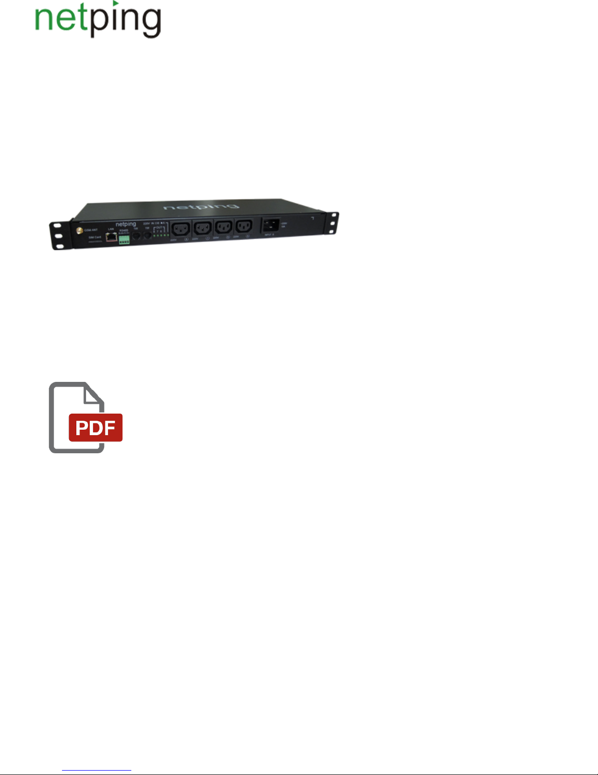
[Docs] NetPing 8/PWR-220 v3/SMS
Copyright © NetPing east Co., Ltd E-mail: Phone:+886-2-23121582[email protected]
Page 4

[ENG] Netping 8/PWR-220 v3/SMS, User guide
Copyright © NetPing east Co., Ltd E-mail: Phone:+886-2-23121582[email protected]
Page 5

[8PWR] Copyright and Disclaimer
The information, contained in this document, can be changed by a manufacturer without a prior notice.Although every effort was made to make the
information in this document accurate and without errors, a manufacturer is not liable for their possible presence and for the consequences that may
result from the errors herein. A manufacturer is not liable if supplied equipment, software and this user guide does not correspond to expectations of a
user and his/her opinion about where and how to use all the above.All copyrights on supplied devices, described in this User Guide, as well as firmware
and software of devices and this User Guide belong to NetPing global Ltd. Сopying, replication and translation of this user guide to other
languagesare not allowed without a prior written permission of a rightholder. Copying, replication, changing, disassembling of provided software are
For the part of software that is provided in source codes, there is anot allowed without a prior written permission of a rightholder.
separate license agreement, which defines an order of its use and modification. Other trademarks used in this description belong to corresponding
rightholders.
Developer and manufacturer:
NetPing global Ltd
Copyright © NetPing east Co., Ltd E-mail: Phone:+886-2-23121582[email protected]
Page 6

[8PWR] Introduction
This user guide helps to become familiar with an operation of a device and get an idea about its functionality and technicalNetping 8/PWR-220 v3/SMS
specifications as well as prepare a device for an operation.
A User Guide is designed for network administrators and users, who set up or operate a device. To work with a device properly, a user must have an
idea about the principles of building and functioning of local networks as well as possess the next knowledge and skills:
Basic knowledge in the area of local and global networks;
Basicknowledgeintheareaofarchitectureandprinciples of work of TCP/IP networks;
Basic knowledge in the area of architecture and principles of work of Ethernet networks.
Copyright © NetPing east Co., Ltd E-mail: Phone:+886-2-23121582[email protected]
Page 7
[8PWR] Device Overview
In this section a purpose of a NetPing 8/PWRv3/SMS device is described as well as its appearance.
Purpose of a Device
A NetPing 8/PWRv3/SMS device is an IP PDU device on 8 independently managed power supply channels, divided into two groups with four channels.
A device's peculiarity is having two independent power supply inputs. Each input allows to provide a power supply to one or both groups of 4 output
channels. Switching channels between power supply inputs can be done by a command from a web-interface of a device, from an SNMP interface of a
device, with the help of SMS-message or automatically when a power supply disappears on a main input.
Appearance
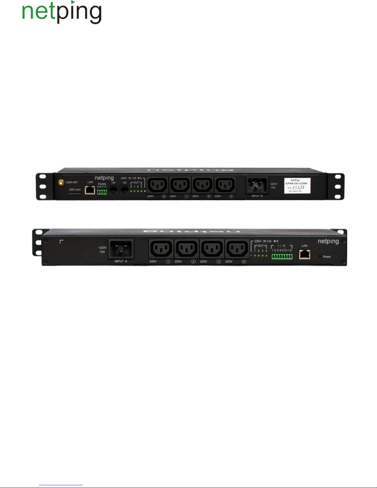
A device is designed in standard dimensions for installation in a 19' rack. A height of a device is 1U. Inputs and output power supply channels are on a
front and back panels of a device. Fasteners for mounting in a rack ("ears") can be bolted toNetPing 8/PWRv3/SMS both front and back, which gives a
possibility to mount a device in a rack by any side. An appearance of device is shown on the pictures.
Front panel:
Back panel:
Copyright © NetPing east Co., Ltd E-mail: Phone:+886-2-23121582[email protected]
Page 8
[8PWR] Sockets and Indication Elements
GSM Slots
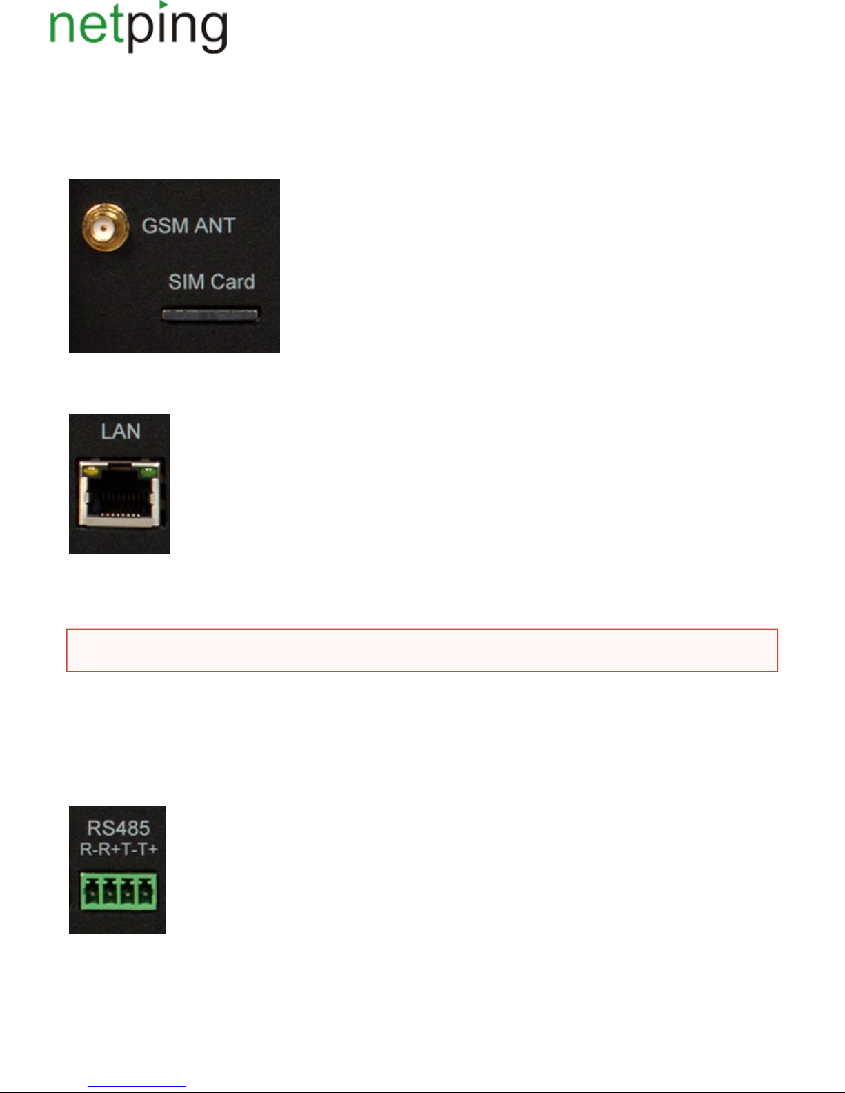
There are sockets on a front panel on the left to connect an external antenna and a slot to install a SIM card.GSMANT SIMCard
LAN Sockets
Ethernet 10/100 BASE-T port. A device has two such ports: one on a front panel and another one on a back panel. Together they form a dual port
Ethernet-switch. One port is used for a network connection, another one is used for additional equipment connection (another NetPing device,
administrator's laptop, etc.), which gives an opportunity to avoid installing of an additional switch on a remote site. The ports are equivalent, anyone
can be used for a network connection.
The Ethernet ports have two LEDs. A left one is its glowing means that a device is turned on, its blinking means transferring packages to aCPU,
network. A right one is its lighting means having "link" on this port, its blinking means receiving packages from a network.Link,
RS485 Socket
An RS485 socket is used to connect RS485 devices. An RS485 port can work in one of two modes: either as an RS485– Ethernet interface converter by
a TCP protocol or in an electricity meter CE102 (Energy meter)protocol analysis mode.
1W Sockets
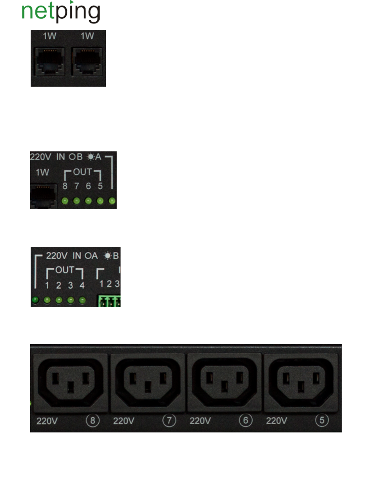
1W sockets are used to plug sensors of a model line V4, which are built on a 1Wire technology.
Important!Connecting both ports to an Ethernet switch with a disabled STP protocol will cause to creation of a loop in an Ethernet segment.
Copyright © NetPing east Co., Ltd E-mail: Phone:+886-2-23121582[email protected]
Page 9
Power Supply Channels Status Indication
On a front panel there are LEDs that indicate a status of the second group of power supply channels. Channels 5 - 8 are included into this group. A
status of each channel is represented by a corresponding LED of an group. A LED is glowing when there is a voltage on an output (a relay isOUT
closed).
220vINOB *A LED shows from what input the second group of channels is fed. A LED glows when a power supply is fed from an input A, which is
located on a back panel of a device.
On a back panel there are LEDs that indicate a status of the first group of power supply channels.Channels 1 - 4 are included into this group. A status
of each channel is represented by a corresponding LED of an group. A LED is glowing when there is a voltage on an output (a relay is closed).OUT
220vINOA *B LED shows from what input the first group of channels is fed. A LED glows when a power supply is fed from an inputB, which is
located on a front panel of a device.
Power Supply Channels
On a front panel there is the second group of power supply channels, with numbers of channels 5 – 8.
On a back panel there is the first group of power supply channels, with numbers of channels 1 -4.
Copyright © NetPing east Co., Ltd E-mail: Phone:+886-2-23121582[email protected]
Page 10
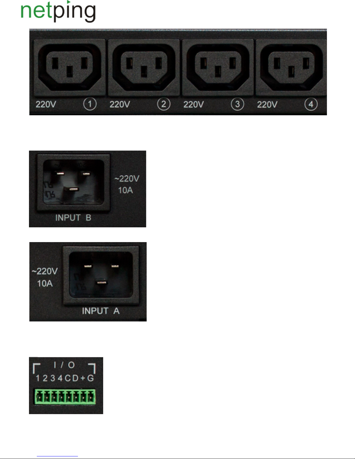
Power Supply Inputs
On a front panel there is a power supply input B.
On a back panel there is a power supply input A.
Sensor Plugin Terminals
On a back panel there is a terminal block for sensors plugin. Assignment of the terminals is from left to right: IO1, IO2, IO3, IO4, SC, SD, +5V, GND.
Copyright © NetPing east Co., Ltd E-mail: Phone:+886-2-23121582[email protected]
Page 11
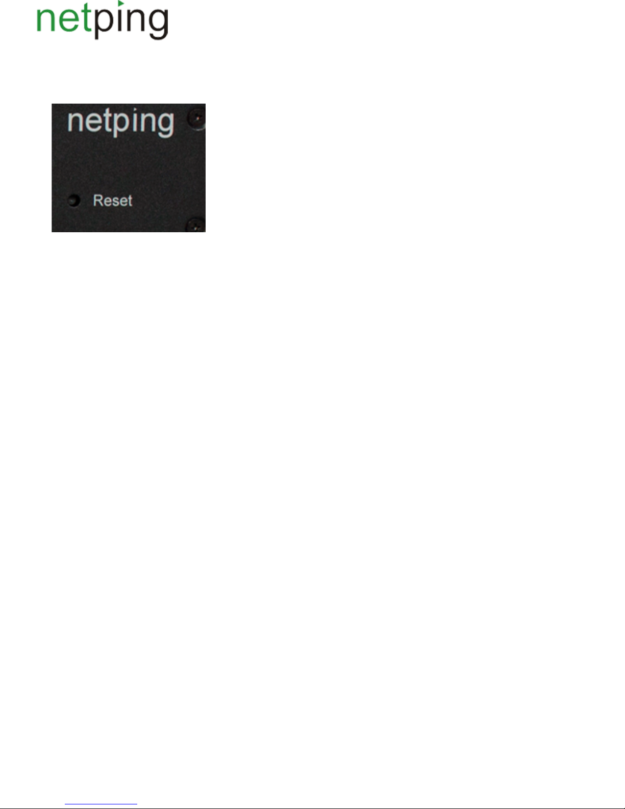
Reset Button
A button is located on a back panel of a device. It is designed to reset settings to default values. To reset settings, press the button with aReset Reset
sharp object and hold it while turning on a device.
Copyright © NetPing east Co., Ltd E-mail: Phone:+886-2-23121582[email protected]
Page 12

[8PWR] Power Supply Channels Management
Channels Management
A NetPing 8/PWRv3/SMS device has eight independent power supply channels. Each channel is managed by a normally closed relay. A relay and tracks
have a big power capacity reserve, which provides a high resistance of a device to overloading.
Each channel can be turned on or turned off independently from others by a command from a web-interface, by an SNMP command or an
SMS-message. Likewise it is possible to automatically turn on or turn off a power supply channel according to a schedule or using a functionality of a
Watchdog or a Logic. There is a need to remember that when a channel is managed by a functionality of a Watchdog or a Logic, it cannot be turned on
or turned off manually (through a web-interface, SNMP, SMS).
Inputs Reservation
A device supports power supply inputs reservation. With this purpose, outputpower supply channels are divided into two groups, with four channels in
each one. Group 1 – channels 1 - 4, Group 2 – channels 5 - 8. For each group a main input is set (1 or 2). Both groups can use the same input as a main
one.
In cases of failure of a main input, a group of channels can be switched to a backup input - it is optional and is configured in a web-interface of a device.
After recovery of a main input a group of channels returns back to it either automatically or by an administrator's command. This behavior is also
programmed in a web-interface of a device. Switching of a group of output channels from one input to another can be done from a web-interface, by an
SNMP command, SMS-message.
All switches between the inputs occur with a two-second power supply turning off of a group of channels.
Device's software guarantees consequent turning off (and consequent turning on) of output power supply channels while switching from a main input to
a backup one to reduce a value of the switched current.
Connecting a Load to Output Channels
When connecting a load to output power supply channels there is a need to take into account capacity limits of a NetPing 8/PWRv3/SMS device. A
maximum capacity of each channel separately is 1500 Watts. A maximum total capacity of four channels in one group is 1725 Watts. I.e., if a consumer
with a maximum capacity of 1500 Watts is connected to a channel1, then it is possible to connect a total load no more than 225 Watts to channels 2,3,4.
Each input can provide 3500Watts, therefore both groups of power supply channels can be fed from one input (1725Watts + 1725Watts = 3500Watts).
Copyright © NetPing east Co., Ltd E-mail: Phone:+886-2-23121582[email protected]
Page 13
[8PWR] Sensors Plugin
Sensors of Dry Contact Type
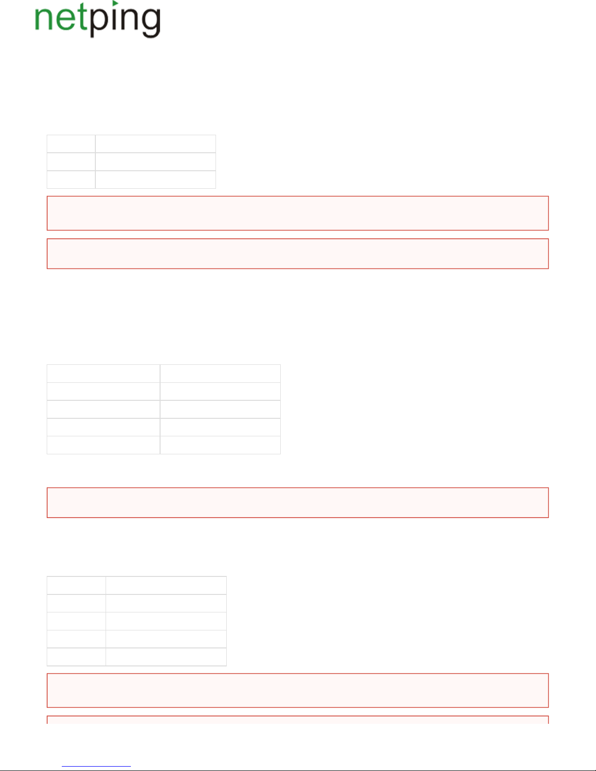
Dry contact sensors are: door opening sensors, buttons and other sensors, which mechanism is in opening/closing a conductor. A sensor is connected
with two wires to an IO line of a device according to the table (an order of plugging wires does not matter).
Sensor Flex Netping 8/PWRv3/SMS Terminal
First wire – 1One of IO lines /2/3/4
Second wire G
A sensor is packaged with an inseparable cable, withconnectors on the ends. A cable length can be increased with the help of flat cable extenders of
sensor, which are sequentially plugged one into another. Or it can be done independently with the help of any wire with a minimum cross sectionRC-4
of 0,4 mm . Maximum allowable length of a flat cable is 100 m.
2
Temperature Sensors
TS- and WT- temperature sensors are plugged in by a four-wire line according to the table.
Sensor Flex Netping 8/PWRv3/SMS Terminal
Labelled wire (red). C
Second wire after a labelled one D
Third wire after a labelled one +
Fourth wire after a labelled one G
It is possible to plug up to 8 temperature sensors to a device – four TS-sensors and four WT-sensors. Sensors are connected in a parallel to the same
terminals.
Leakage Sensors
A leakage sensor is connected by a four-wire line according to the table.
Sensor Flex Netping 8/PWRv3/SMS Terminal
Green. One of IO lines – 1/2/3/4
Yellow (White) G
Red +
Black G
! Important Sensors of a dry contact type, a 220 V occurrence sensor, a leakage sensor and others are plugged to IOlines of a device. You can
plug any four sensors out of this set.
!Important A corresponding IOline should be set to an input mode in settings of a device.
Important! It is prohibited to plug sensors with the same numbers to a device.
Important! Sensors of a dry contact type, a 220 V occurrence sensor, a leakage sensor and others are plugged to IOlines of a device. You can
plug any four sensors out of this set.
Copyright © NetPing east Co., Ltd E-mail: Phone:+886-2-23121582[email protected]
Page 14
A sensor is packaged with an inseparable cable, withconnectors on the ends. A cable length can be increased with the help of flat cable extenders of
sensor, which are sequentially plugged one into another. Or it can be done independently with the help of any wire with a minimum cross sectionRC-4
of 0,4 mm . Maximum allowable length of a flat cable is 100 m.
2
220V Occurrence Sensors
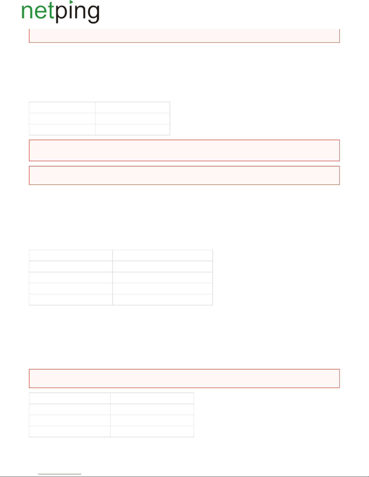
A 220V occurrence sensor .is pugged by a two-wire line according to the table
Sensor Flex Netping 8/PWRv3/SMS Terminal
Output. Black-and-white wire – 1/2/3/4One of IO lines
Common. Black wire G
A sensor is packaged with an inseparable cable, withconnectors on the ends. A cable length can be increased with the help of flat cable extenders of
sensor, which are sequentially plugged one into another. Or it can be done independently with the help of any wire with a minimum cross sectionRC-4
of 0,4 mm . Maximum allowable length of a flat cable is 100 m.
2
IR Transceiver IRC-TRv2
IR transceiver is plugged by a four-wire line according to the table:
Sensor Flex NetPing 8-PWR-220 v3/SMS Terminal
Labelled wire (red). C
Second wire after a labelled one D
Third wire after a labelled one +
Fourth wire after a labelled one G
Подключениерозеток NetPing AC/DIN
При подключении розетки к устройству задействованы все провода, кроме коричневого. IO линию, к которой подключена розетка AC/DIN,
необходимо перевести в состояние "выход". При состоянии лог. 0 на IO линии 220В будет присутствовать на розетке, нагрузка будет
включена. При состоянии лог. 1 на IO линии розетка будет обесточена, нагрузка выключена.
Шлейф датчика КлеммаNetPing 8-PWR-220 v3/SMS
Красный провод (маркированный) +
Черный провод G
Синий провод Одна из IO линий – 1/2/3/4
Important! A corresponding IOline should be set to an input mode in settings of a device.
Important! Sensors of a dry contact type, a 220 V occurrence sensor, a leakage sensor and others are plugged to IOlines of a device. You can
plug any four sensors out of this set.
Important! A corresponding IOline should be set to an input mode in settings of a device.
Важно! Коричневый провод не используется и должен остаться неподключенным!
Copyright © NetPing east Co., Ltd E-mail: Phone:+886-2-23121582[email protected]
Page 15

Для коммутации нагрузки в NetPing AC/DIN используется реле с нормально замкнутыми контактами. Это означает, что, если управляющий
провод никуда не подключен, 220В будет присутствовать на розетке и нагрузка будет включена.
A sensor is packaged with an inseparable cable, withconnectors on the ends. A cable length can be increased with the help of flat cable extenders of
sensor, which are sequentially plugged one into another. Or it can be done independently with the help of any wire with a minimum cross sectionRC-4
of 0,4 mm . Maximum allowable length of a flat cable is 100 m.
2
Copyright © NetPing east Co., Ltd E-mail: Phone:+886-2-23121582[email protected]
Page 16
[8PWR] Setting Parameters to Default Values (to the Factory Settings)
Resetting parameters to the factory settings is necessary in the following cases:
A loss of a login and/or password to a web interface of a device;
A lack of information about current IP address of a device;
In some cases after a device software update.
A procedure of resetting parameters to the factory settings changes all customizable parameters of a device to the default ones. (IP and MAC addresses,
access filters, a user name, a password, etc.).
To reset parameters to default settings, fulfill the next actions sequentially:
Turn off a power supply of a device;
Press the Reset button (a button Set for a Uniping v3 device);
Turn on a power supply of a device, continuing to hold Reset button pressed for 15-20 seconds;
Release the button. All parameters of a device are set to default settings.
After resetting parameters to default settings there is a need to do an initial configuration of a device.
On default, the next parameters of a device are set:
User name: visor
Password: ping
IP address: 192.168.0.100
Subnetwork mask: 255.255.255.0
Gateway: not set
SNMPcommunity: SWITCH
MAC-address: 00 a2 xx xx xx xx
Here xx xx xx xx corresponds to a serial number of a device. Thus, all devices after being manufactured have unique MAC-addresses.
Copyright © NetPing east Co., Ltd E-mail: Phone:+886-2-23121582[email protected]
Page 17
[8PWR] Using IO Lines for External Devices Management (in an Output Mode)
Input-Output lines of a device can be used for an input work as well as in an output mode for managing external devices.(IO)
A device has four IO lines, corresponding to contacts I1 –I4 of a terminal block. Lines configuration for work as an input or an output is made through
a controlling web-interface of a device. All four IO lines can be customized independently.
Lines management can be done by SNMP commands, via a web-interface or by SMS-commands, sent to a device.
Such device functions as a watchdog and a scheduled load management are NOT AVAILABLE for IO in an output mode.
Examples of using:
Remote servers reboot – an imitation of pressing “reset”;
Remote management of an alarm, a light, a fan;
Management of an electric lock, electric gates on a remote object;
Management of smart home elements - watering flowers, opening-closing louvers, water pump, heating boiler, heaters, etc. Remote
management of a power installation (diesel generator, gasoline).
Electric specifications of a line in an output mode:
High level (logic «1») – 5 V voltage, 1,5 mA current.
Low level (logic «0») - 0 V voltage, up to 150 mA current.
It is acceptable to use intermediate relays with a power supply voltage 12 V from an external source.
A ready socket can be used for IO lines connection NetPing AC/DIN socket
In addition, we can advise ready assembly relays of other manufacturers, which can be connected to our devices:
http://www.masterkit.ru/shop/smarthome/executive-devices/1327359 - a power module switch (4 independent channels, 2 kWt 10A each)MP701
http://www.masterkit.ru/shop/smarthome/executive-devices/1326291 - a load switching relay up to 6A 12V
http://www.masterkit.ru/shop/smarthome/executive-devices/1494003 - a power module on a basis of a powerful relay with an optocoupler forMP220
managing a load up to 4 kWt (20A).
Therefore, when using IO lines in an output mode, it is possible to independently manage four external devices.
For more detailed information, please contact a technical support[email protected]
Important! A correct electrical coordination of IO lines is required when connecting external executive
devices.
Important! IO lines do not have a galvanic isolation with a device! Remember about electrical safety when
using relays that commutate 220 V circuits. All work must be done by specialists with a correspondent
qualification who have a permit to work with such a voltage!
Copyright © NetPing east Co., Ltd E-mail: Phone:+886-2-23121582[email protected]
Page 18
[8PWR] Shipping Kit
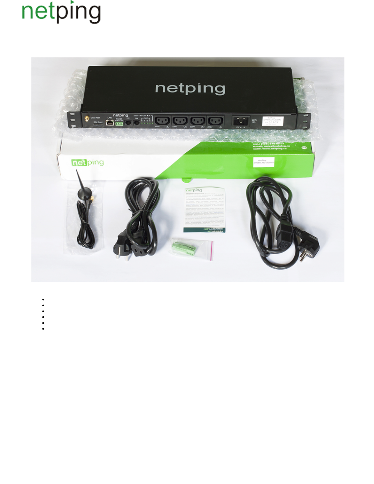
A shipping kit is shown at the picture:
A shipping kit includes:
A device NetPing 8/PWRv3/SMS;
An antenna;
A user guide;
A packing box;
A power cord – 2 pcs.;
Mating terminals – 2 pcs.
Copyright © NetPing east Co., Ltd E-mail: Phone:+886-2-23121582[email protected]
Page 19
[8PWR] Operating and Storage Conditions
A device is designed for continuous round the clock operation indoors. In operating conditions of use, a device is resistant to an environment with
temperature in a range of 0°С - +40°С (32 – 104 degrees Fahrenheit) and relative humidity in a range of 5% - 95 % at 25°С (77 degrees Fahrenheit)
without moisture condensation. A device should be protected from direct moisture and direct sun light.
A construction of a device provides a reliable uninterrupted work during a long period of time without maintenance.Highly developed functionality of
remote setting and configuration of a device allows changing any parameters remotely and centrally for the most of the devices.
Devices should be stored in a temperature range between - 40°С and +70°С.
In rooms for keeping a device, a content of dust, acid and alkali gases, aggressive gases and other harmful impurities causing corrosion, should not
exceed a content of corrosion-active agents for atmosphere of type 1.
Important! A device must be connected to a power supply socket with a grounding contact or a hole, where a contact, located at an outlet
and connected to a ground wire, is inserted. Grounding must be performed according to the State Standard Р 50571.21-2000. An infraction
of this rule is aviolation of a device operation conditions and may be dangerous to human lives as well as damage other devices!
Copyright © NetPing east Co., Ltd E-mail: Phone:+886-2-23121582[email protected]
Page 20

[8PWR] Warranty
The manufacturer guarantees normal operating of the product within 24 months from the date specified on the warranty sticker if a buyer follows
operating and storage conditions. Manufacturer warranty applies only to failure of a device, which occurred because of defects in manufacturing
process of products and components used. If during a warranty period, the manufacturer receives a notice of such defects, it will repair or exchange a
product (by its own discretion). If the manufacturer is unable to repair or replace a flawed item during a period of time determined by the current
legislation, the manufacturer according to a customer’s wish can return the amount paid for the product at the time of purchase. The manufacturer
provides a limited warranty on firmware and device configuration software. In case of detecting any errors in software, which became known to the
manufacturer on its own or from a customer, the manufacturer will fix these errors within a reasonable time and provide an update for the
customer.Only the errors that block normal use of the device at conditions and for performing functions, described in this User Guide, are subject to
mandatory fix.This warranty does not apply to cases, when defects appear because of: a misuse of a device, any modifications of a device without a
written permission of the manufacturer, opening up a device, except cases, foreseen by this description, repairing by unauthorized personnel, using or
storing a device out of the range of allowable temperature and humidity, pressure, a software modification, and the reasons, listed below:
A device failed because of the problems in a public electric network, plugging a device into power supply networks with invalid parameters,
absence of grounding, etc. (power fluctuations and surges, overloading, etc.);
A device failed because of a liquid inside;
A device failed as a result of extreme temperatures;
A device failed because of mechanical damage;
A device failed because of connecting a power supply unit with invalid output voltage or a defective power supply unit;
There are foreign objects, insects, etc inside the enclosure;
During operation, a voltage bigger than an allowable voltage range by the Ethernet standard has been supplied to the ports of a device.
Copyright © NetPing east Co., Ltd E-mail: Phone:+886-2-23121582[email protected]
Page 21

[ENG] NetPing 8/PWR-220 v3/SMS, Firmware description
Copyright © NetPing east Co., Ltd E-mail: Phone:+886-2-23121582[email protected]
Page 22

[ENG] 1. [DKSF 48.4 IU] Introduction
This document describes a functionality of firmware for the device .DKSF 48.4.X NetPing 8/PWR-220 v3/SMS
NetPing 8/PWR-220 v3/SMSwith firmware version supports the next management interfaces:DKSF 48.4.X
HTTP (Web interface, url-encoded commands);
SNMP v1;
SMS
The document describes settings and an operation order in these management interfaces.
Physical specifications of the device, its controls and indicators as well as an order of connecting a device and external sensors are described in a user
guide for device. A user guide can be downloaded from the page of the device at the websiteNetPing 8/PWR-220 v3/SMS NetPing 8/PWR-220 v3/SMS
of the companyhttp://www.netpingdevice.com/products/netping-8-pwr-220-v3-sms
The information, contained in this document, can be changed by a manufacturer without a prior notice.Although every effort was made to make the
information in this document accurate and without errors, a manufacturer is not liable for their possible presence and for the consequences that may
result from the errors herein. A manufacturer is not liable if supplied equipment, software and this user guide does not correspond to expectations of a
user and his/her opinion about where and how to use all the above.All copyrights on supplied devices, described in this User Guide, as well as firmware
and software of devices and this User Guide belong to NetPing global Ltd. Сopying, replication and translation of this user guide to other
languagesare not allowed without a prior written permission of a rightholder. Copying, replication, changing, disassembling of provided software are
For the part of software that is provided in source codes, there is anot allowed without a prior written permission of a rightholder.
separate license agreement, which defines an order of its use and modification. Other trademarks used in this description belong to corresponding
rightholders.
Developer and manufacturer:
NetPing global Ltd
Copyright © NetPing east Co., Ltd E-mail: Phone:+886-2-23121582[email protected]
Page 23

[ENG] 2. [DKSF 48.4 IU] Receiving a Main Information about a Device
Copyright © NetPing east Co., Ltd E-mail: Phone:+886-2-23121582[email protected]
Page 24
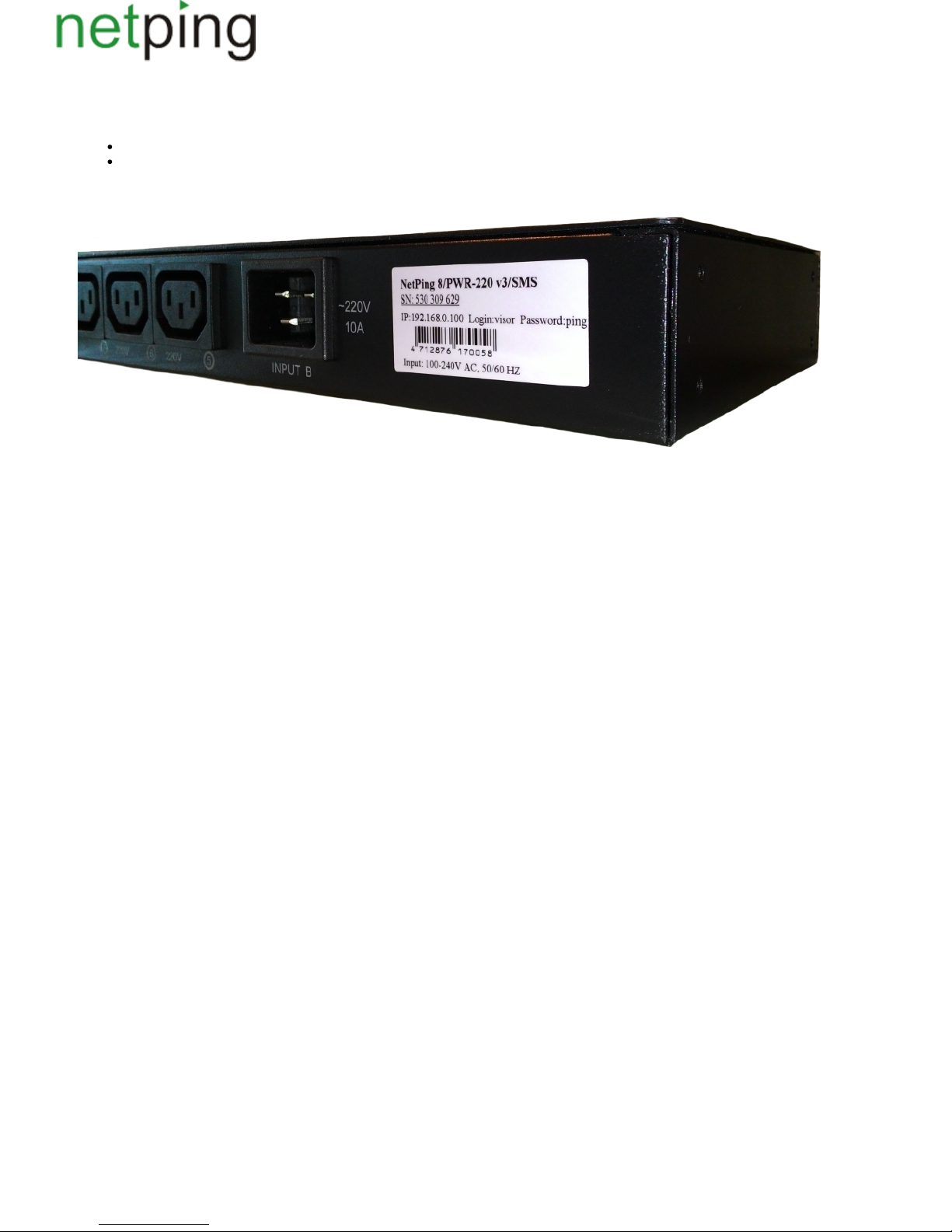
[ENG] 2.1. [DKSF 48.4 IU] Default Username and Password
Default username and password for connecting to a web interface are as follows:
Login: visor
Password: ping
This information is indicated at the case of the device:
Copyright © NetPing east Co., Ltd E-mail: Phone:+886-2-23121582[email protected]
Page 25
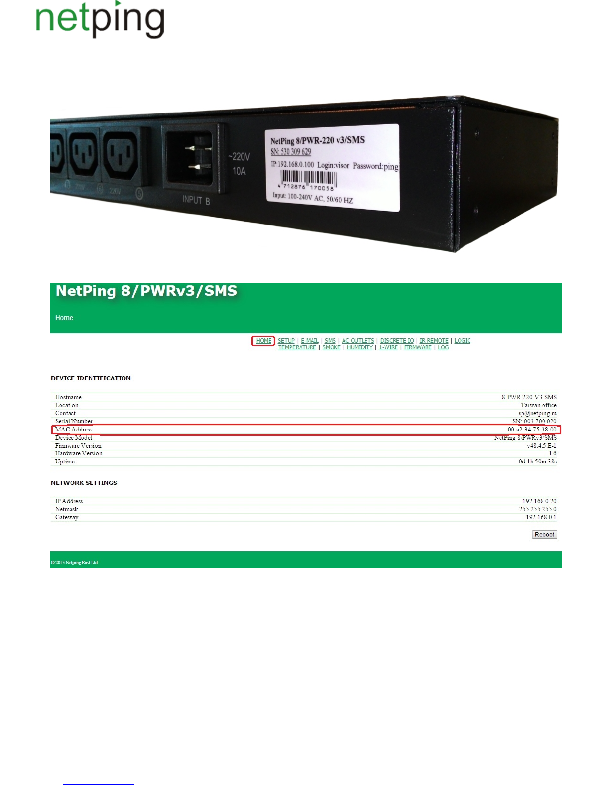
[ENG] 2.2. [DKSF 48.4 IU] How to Know a Default IP Address and MAC Address of a Device?
A default IP address is indicated at the case of the device:
MAC address of a device can be found at the home page of a device web interface:
where:
MAC addressis a unique physical address of a device in the Ethernet network.
Copyright © NetPing east Co., Ltd E-mail: Phone:+886-2-23121582[email protected]
Page 26
[ENG] 2.3. [DKSF 48.4 IU] Connecting a Device with a Default Authorization to a Web Interface
Web Interface
In this device management software, an embedded web interface is implemented. To set up device parameters you need to go to an IP addressversion of
of device with the help of an (for example, Internet Explorer, FireFox, Google Chrome. etc.).Internet browser
For instance:
Use a command ping from a command line to check a connection with a device:
ping 192.168.0.100
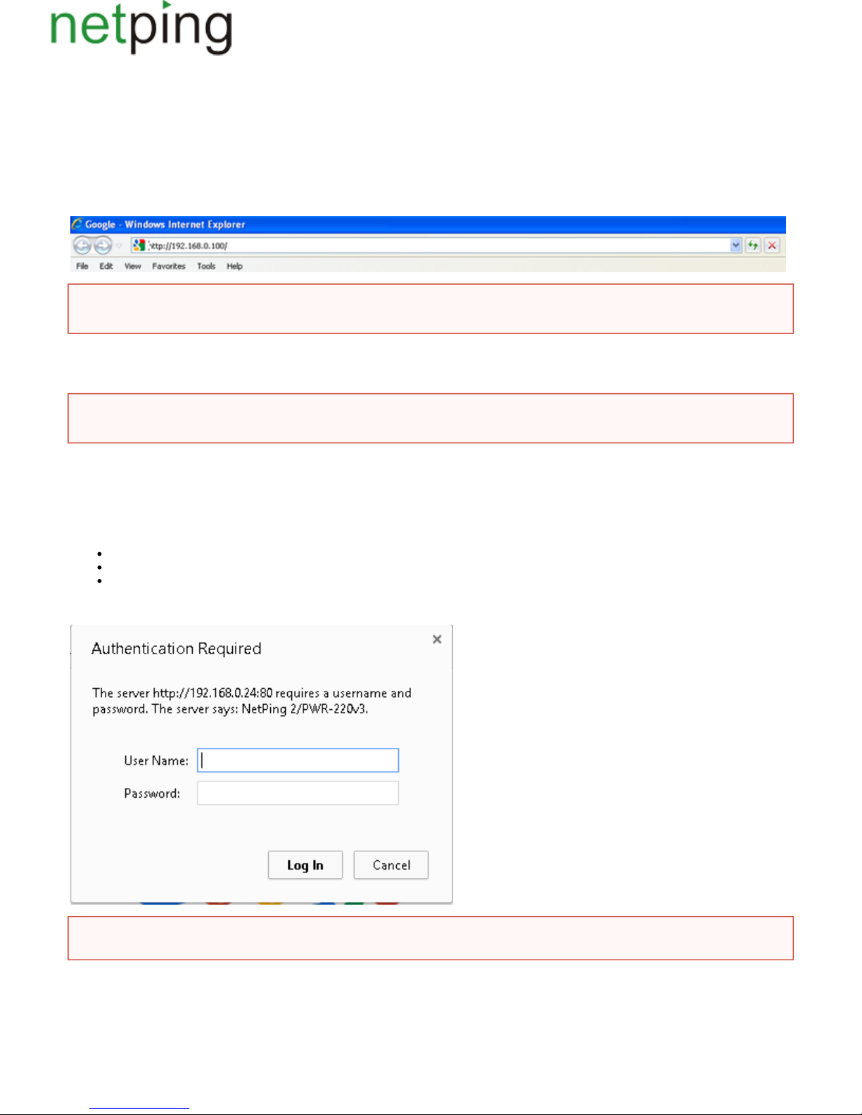
Authentication
While connecting a device will request authentication by entering login and password.
On default:
Address for connecting to a device:http://192.168.0.100/
User:visor
Password:ping
When working in InternetExplorer web interface operation speed can be decreased GoogleCh. It is recommended to use the latest version of
rome.
IP address of a computer should be in the same subnetwork with IP address of a device! For example, if a device has an IP address
192.168.0.100, then a computer should have address 192.168.0.11 mask 255.255.255.0
fter the first turning on a device as well as after resetting its parameters.Make sure that a device responds to ping 192.168.0.100 a
Copyright © NetPing east Co., Ltd E-mail: Phone:+886-2-23121582[email protected]
Page 27
[ENG] 2.4. [DKSF 48.4 IU] I Need to Know a Firmware Version, a Hardware Version, a Serial Number, a Model
of a Device and Its Uptime
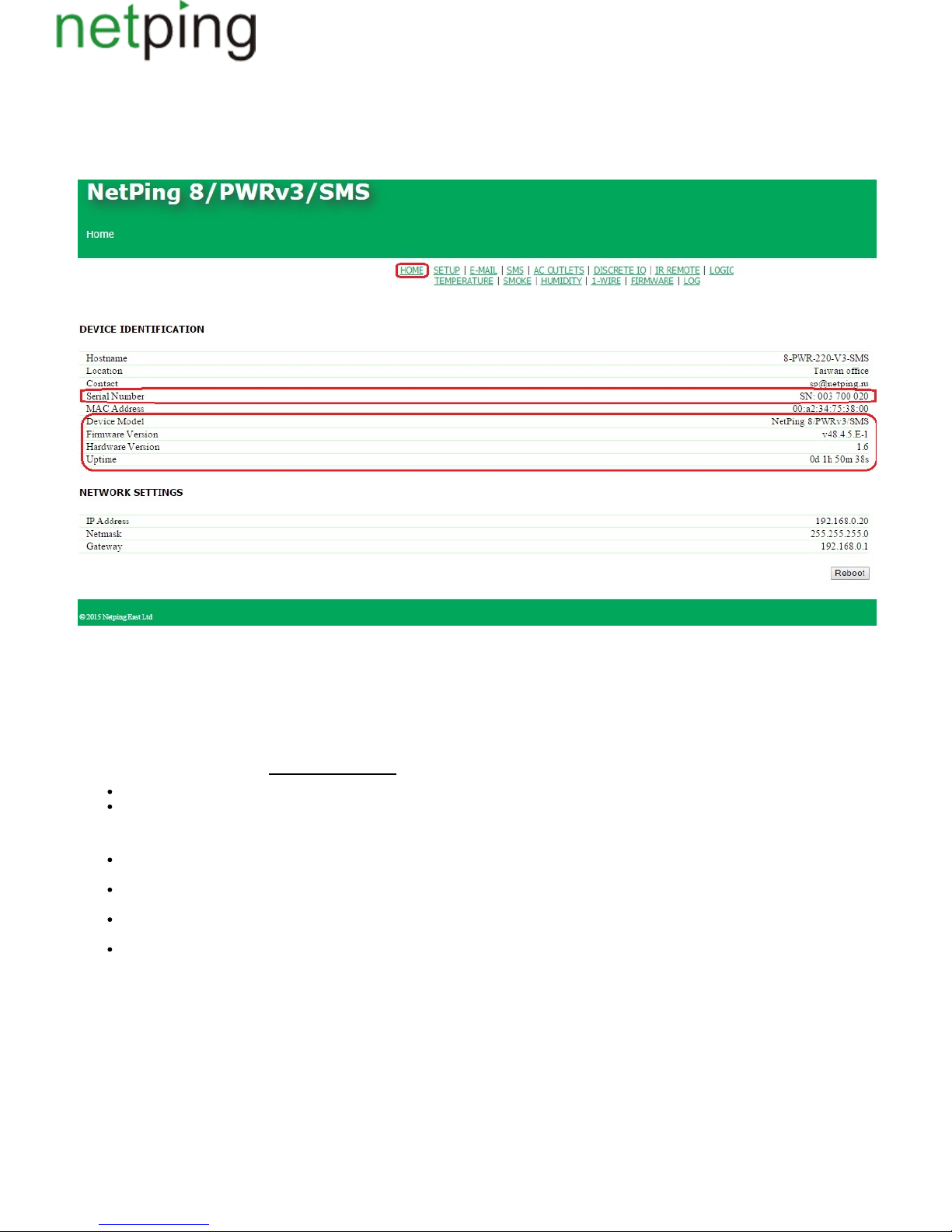
The information about a serial number, a model of a device, a firmware version, a hardware version and an uptime can be seen at the main page of a
web interface of a device:
where:
Serial number is a unique identification number of a device. It must coincide with a number at the sticker of a device. A serial number of a device
cannot be altered.
Device Model– a model name, which is indicated at the case of a device and at the web interface.
Firmware is a current firmware version, which is installed at a device.Version
A firmware version looks like DKSF PPP.VV.SS.C-M(for example, DKSF 707.2.1.A-1), where:
– is a special prefix for all firmware of the company ;DKSF NetPing Co Ltd
PPP– is a number of a model of a device, for which this firmware is designed.
Usually but not necessarily, project numbers coincide with the project numbers of a device hardware platform.
VV– is a version number. Versions are numbered starting from 1. A version number is changed to the next one if a functionality is significantly
extended or changed in the development process;
SS– is a subversion number. A subversion number if changed every time when firmware is updated, including fixing errors and updating
internal modules, optimisation;
С– is a symbol indicating a type of the firmware version. А is a stable Russian firmware version, В is a version for testing or the first version of
the new firmware. E is a stable version with an English interface;
Мis a numeric suffix indicating a modification (variant) of a model of a device, for which this firmware is made
is a PCB version and/or a device configuration.Hardware Version
Uptime – is a device uptime from the moment of the last turning on or rebooting.
Copyright © NetPing east Co., Ltd E-mail: Phone:+886-2-23121582[email protected]
Page 28
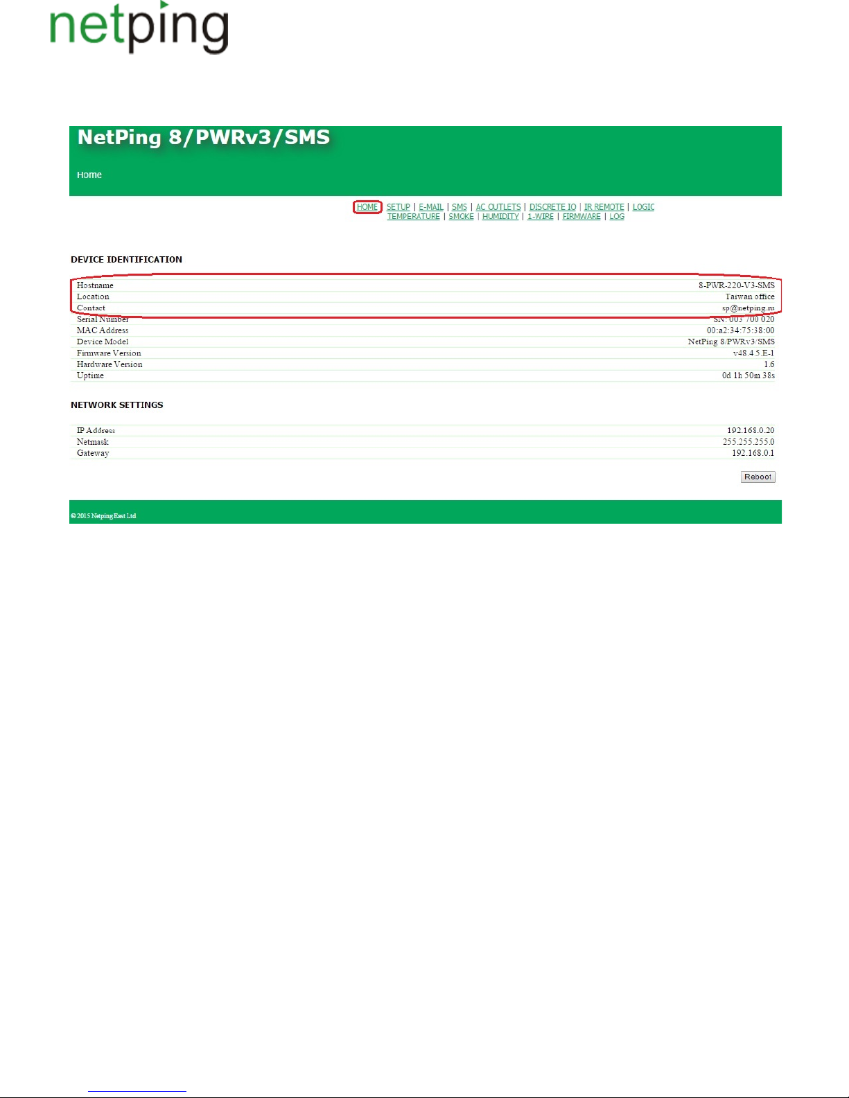
[ENG] 2.5. [DKSF 48.4 IU] Where Can I See a Name, a Location and Contacts of a Device?
A name, a location and contacts can be seen at the home page of a device web interface:
where:
Hostnameis a domain name of a device. It allows to distinguish several Netping devices of the same type by their names. A name is displayed at the
home page and in the heading of a web interface, is sent in Syslog notifications and is available via SNMP – OID «sysName».
Location is a description of the installation place of a Netping device. It is displayed at the home page and in the heading of a web interface. It can be
accessed via SNMP – OID«sysLocation».
Contact is an administrator's contact (usually, an e-mail). This value is available via SNMP – «sysContact».
Copyright © NetPing east Co., Ltd E-mail: Phone:+886-2-23121582[email protected]
Page 29
1.
2.
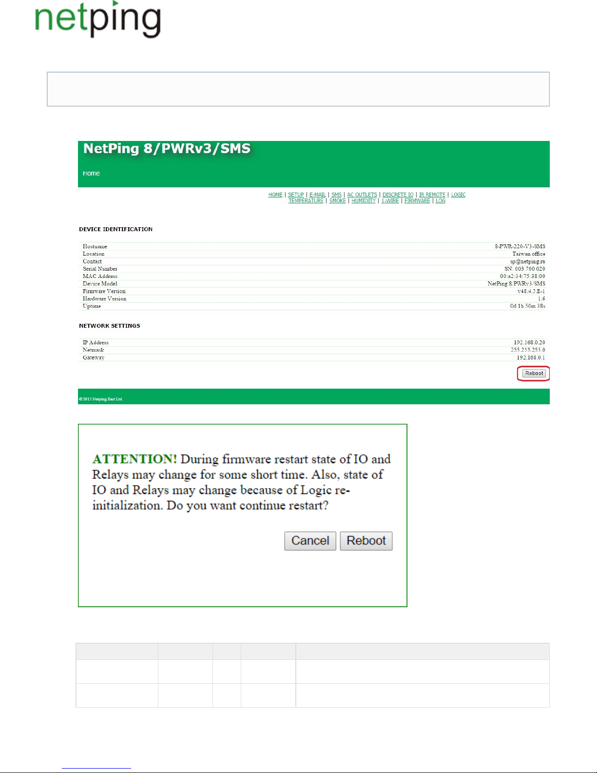
[ENG] 2.6. [DKSF 48.4 IU] How to Reboot a Device?
A NetPingdevice can be rebooted in two ways:
Click the button « at the home page of a web interface of a device.Reboot»
Afterward, a system will display an informational notification confirming a device reboot.
After clicking the button « »CPU LEDs near Ethernet ports will blink. A device will reboot. Its uptime will be zeroed to 0d 0h 0m 0s.Continue
Use an protocol by specifying OID values using the command :SNMP v1 Set
OID Name Type Access Description
.1.3.6.1.4.1.25728.911.1.0 npSoftReboot Integer READ/WRITE Software reboot of a device when writing the value«1» (an analog for rebooting a
device through a web interface)
.1.3.6.1.4.1.25728.911.3.0 npForceReboot Integer READ/WRITE A immediate reboot of a device when writing the value «1» (a processor isforced
reset the same as when turning a power supply on)
When rebooting a device through a web interface, its embedded relays are not rebooted! It works only in the case if a firmware version DKSF
48.2.5 has been installed when manufacturing a device,which includes an improved firmware loader.
Copyright © NetPing east Co., Ltd E-mail: Phone:+886-2-23121582[email protected]
Page 30

[ENG] 3. [DKSF 48.4 IU] Basic Configuration
Copyright © NetPing east Co., Ltd E-mail: Phone:+886-2-23121582[email protected]
Page 31
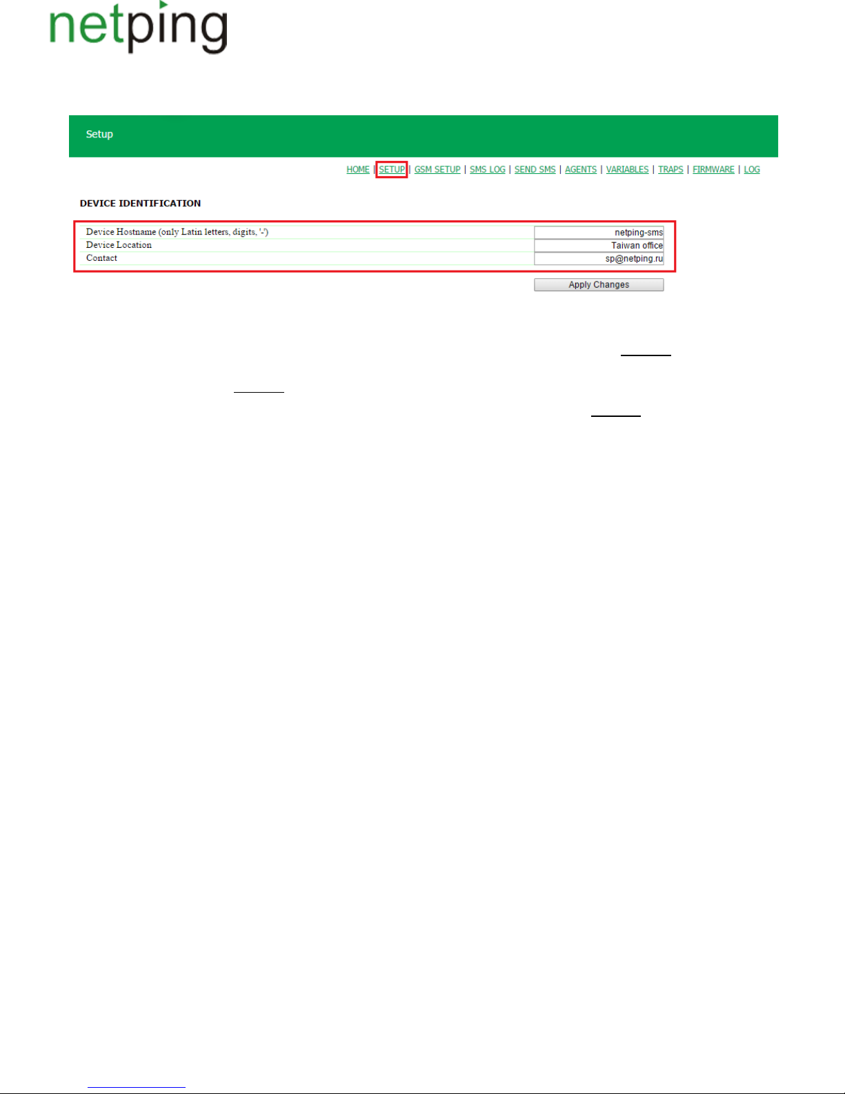
[ENG] 3.1. [DKSF 48.4 IU] How to Configure Name of a Device, Its Location and Contacts?
To configure a name and a location of a device as well as its contacts, there is a need to go to the page « » of a web interface of a device:Setup
In the section « » it is possible to configure:Device Identification
Device Hostname –is a domain name of a device. It allows distinguishing among several Netping devices of the same type. A hostname is displayed at
the home page and in the heading of a web interface, is sent in Syslog messages and is available via SNMP – sysName. : empty rowOn default
– Device Location is a description of a place of installation of a Netping device. It is displayed at the home page and in the heading of a web interface, is
available via SNMP – sysLocation. : empty rowOn default
Contact –is administrator's contacts (usually, an e-mail). This information is available via SNMP – sysContact. : empty rowOn default
After configuring all necessary parameters, click the button « ».Apply changes
Copyright © NetPing east Co., Ltd E-mail: Phone:+886-2-23121582[email protected]
Page 32
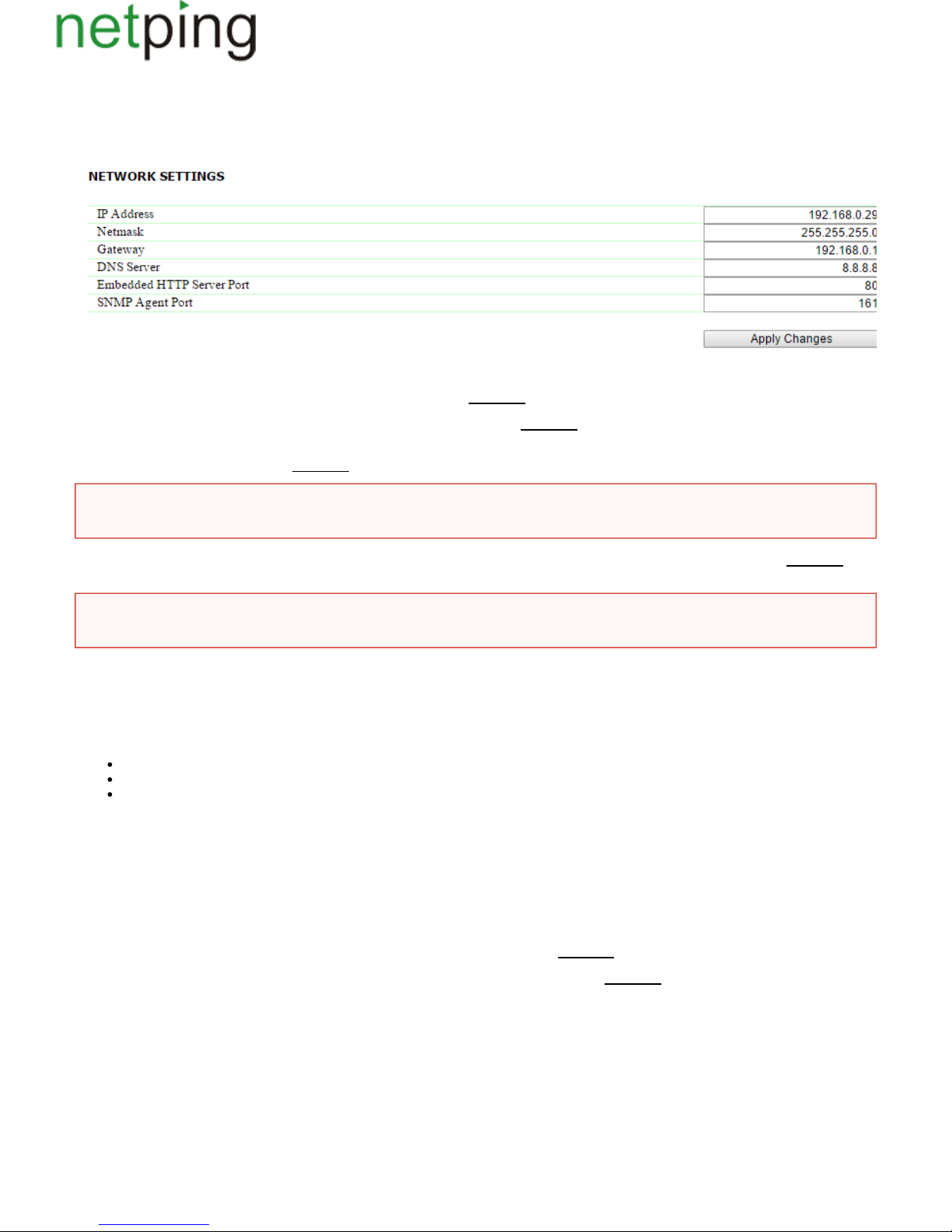
[ENG] 3.2. [DKSF 48.4 IU] Where to Change Settings of a Network Interface?
To change network interface parameters, such as an HTTP port, a server and an SNMP agent, there is a need to go to the page « » of a device webSetup
interface:
In the section « » it is possible to configure:Network Settings
–IP Address is a field for setting up or changing an IP address of a device. :192.168.0.100On default
– Netmask is a field for setting up or changing a subnet mask, where the devices are. :255.255.255.0On default
Gateway –is a field for setting up or changing an IP address of a gateway. The value means a gateway is not specified and packages for other0.0.0.0
subnetworks will not be sent by a device.On default:0.0.0.0
– DNS server is a DNS server address. The value0.0.0.0means a DNS server is not specified, and a device will not send DNS requests. :0.0.0On default
.0
A DNS module works independently from other firmware modules. A DNS module saves responses from a DNS server into a DNS-cache of a device.
Other firmware modules use this cache to determine an IP address, where a package needs to be sent. A request is not sent directly before sending a
DNS package. If there is no correspondent entry in a DNS-cache in the moment of sending a package, then an outgoing package is discarded. A DNS
cache size coincides with the number of hostnames (IP addresses) specified in the settings of a device.
Domain names are resolved and renewed in the next cases:
Firmware start and restart;
Saving settings through a web interface (if a domain name is changed);
A life timeout of a DNS record, specified in the response from a DNS server
When a lifetime of a cache entry is expired, the entry is not removed from a cache. A device updates an expired entry from time to time. Other firmware
modules use an outdated information until the entry is successfully updated.
If a DNS server does not respond, a device repeats its request three times. Afterwards, it repeats the request periodically nearly once a minuteif there is
still no response from a server. The requests are repeated when there is no server response and if there is an error in a server response, including the
error «no such hostname».
– HTTP Server Port is a field for configuring a port number, through which an embedded web interface operates. When connecting through a web
browser to a device with a port number different from 80, there is a need to indicate the URL of the following appearance: :nn, wherehttp://x.x.x.x
x.x.x.x– is an IP address of a device, nn– is a port number, specified in settings of a device. :80On default
SNMP Agent Port– is a field for configuring a UDP port number, which an SNMP agent listens to. :161On default
After setting all necessary parameters, click the button « ».Apply changes
A device will send any outgoing packages to a gateway address. Therefore, there is a need to specify an IP address of a gateway properly if
there is a need to work with a device from other subnetworks.
A DNS server must use a recursive method. Cyrillic domain names are not supported. Domain names longer than 62 symbols are not
supported either.
Copyright © NetPing east Co., Ltd E-mail: Phone:+886-2-23121582[email protected]
Page 33
[ENG] 3.3. [DKSF 48.4 IU] Changing a Username and a Password
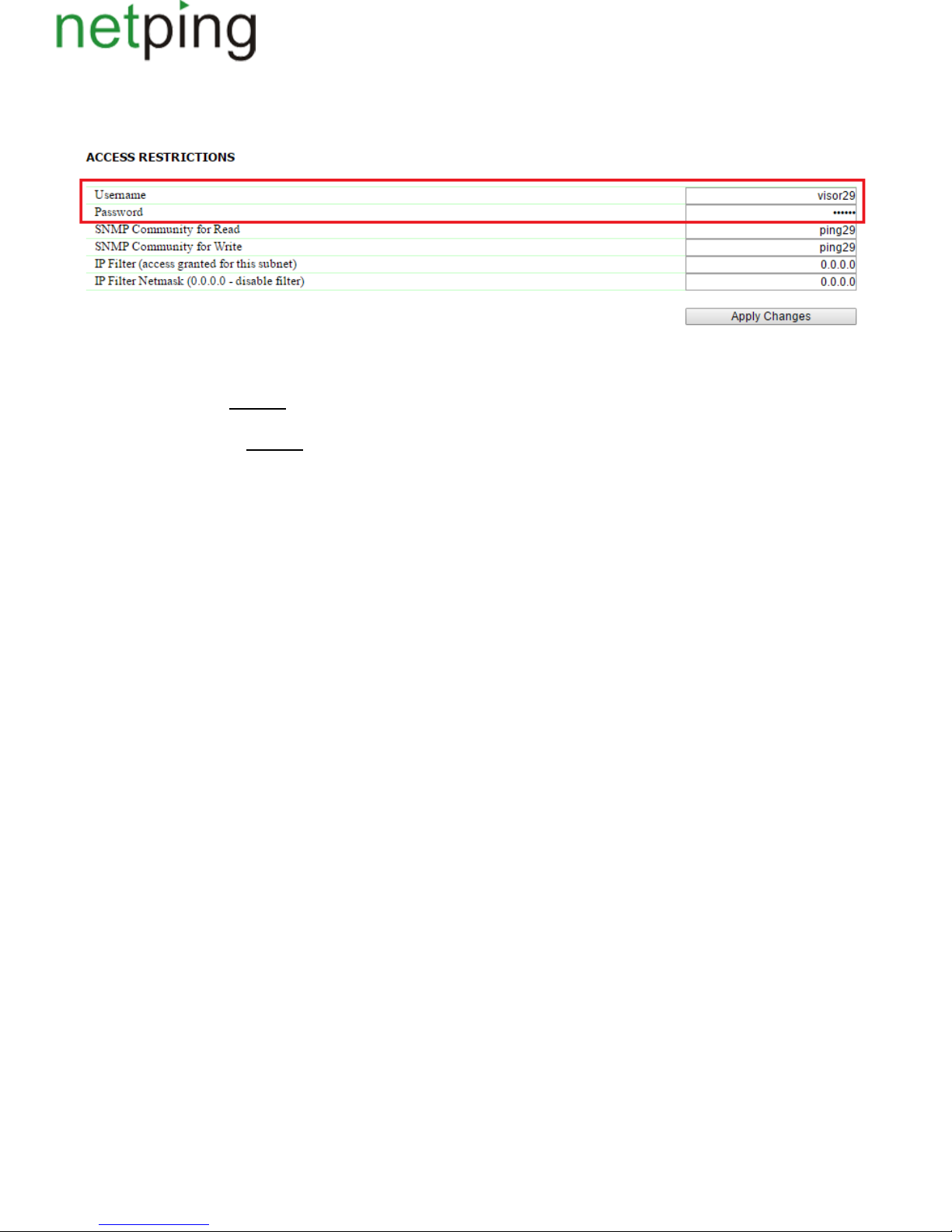
To change a username and a password, there is a need to go to the web page « » of a web interface of a device:Setup
In the section « » it is possible to configure the following:Access Restrictions
Username– is a field for setting up or changing a username when accessing a device through a web interface. Latin letters and numbers are used. Its
maximum size is 16 symbols. :On default visor
Password– is a field for setting up or changing a user's password when accessing a device through a web interface. Latin letters and numbers are used.
Its maximum size is 16 symbols. :On default ping
After setting up all necessary parameters, click the button .« »Apply changes
Copyright © NetPing east Co., Ltd E-mail: Phone:+886-2-23121582[email protected]
Page 34
[ENG] 3.4. [DKSF 48.4 IU] How to Set Community for SNMP?
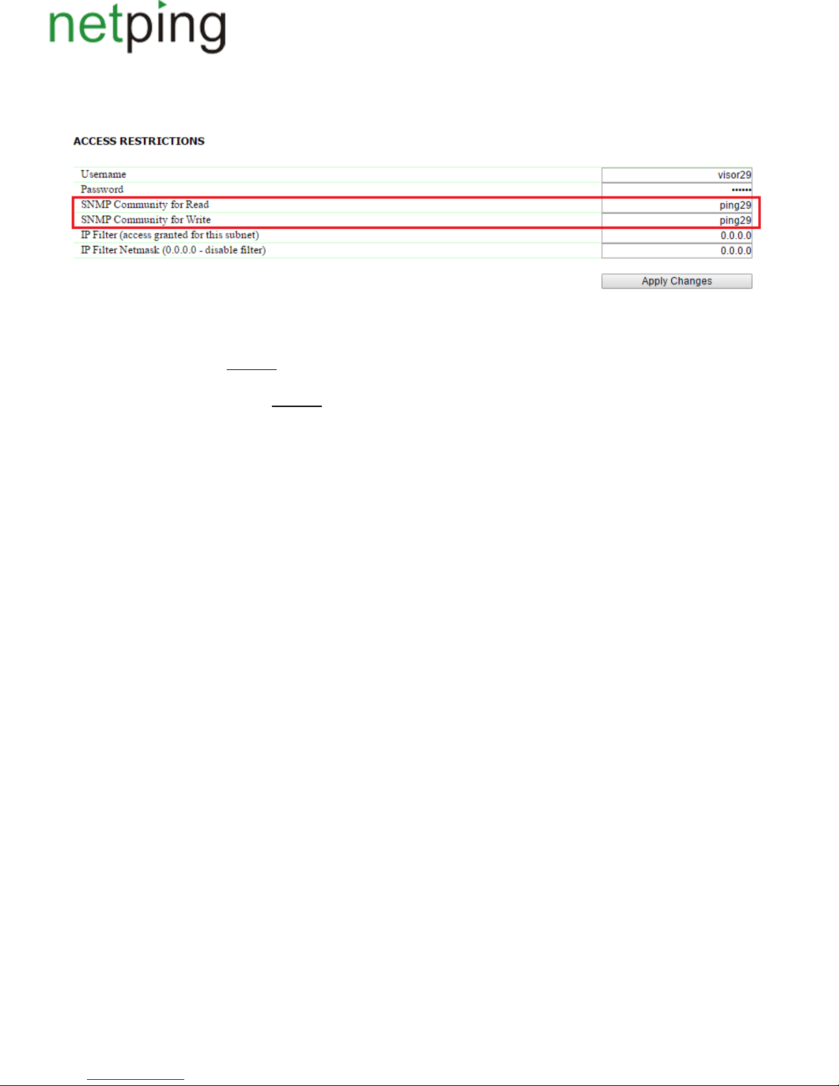
To configure Community, there is a need to go to the web page « » of a device web interface:Setup
In the section« » it is possible to configure:Access Restrictions
Community for Read – is a field for setting up or changing Community for read parameters of a device when accessing a device via an SNMP protocol.
Its maximum size is 16 characters. :On default SWITCH
Community for Write – is a field for setting up or changing Community for write parameters of a device when accessing a device via an SNMP
protocol. Its maximum size is 16 characters. :On default SWITCH
After setting up all necessary parameters, click the button « ».Apply changes
Copyright © NetPing east Co., Ltd E-mail: Phone:+886-2-23121582[email protected]
Page 35
[ENG] 3.5. [DKSF 48.4 IU] How to Restrict Access to a Device?
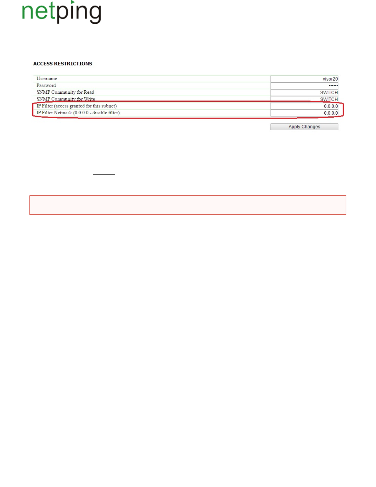
To restrict an access to a device via HTTP and SNMP protocols, there is a need to go to the page « » of a device web interface:SETUP
In the section« », it is possible to configure:Access Restrictions
IP Filteris a field that determines an IP address or a subnetwork, from which it is allowed to configure and browse parameters of a device via HTTP,
SNMP protocols. A subnet mask indicated in the field « » is applied to the address indicated in the field . As a result, thereIP Filter Netmask «IP Filter»
is a subnetwork, from which it is allowed to manage a device. To allow access for an IP address, there is a need to indicate a mask in255.255.255.255
the field « ».IP Filter Netmask :0.0.0.0On default
IPFilter Netmask is a field to set or change the subnet mask filter to access a device. The value means that the access filter is disabled.0.0.0.0 On default
:0.0.0.0
After setting all necessary parameters, click the button « ».Apply changes
When access filter parameters are set, a device will not respond to an ICMP request (ping).
Copyright © NetPing east Co., Ltd E-mail: Phone:+886-2-23121582[email protected]
Page 36
[ENG] 3.6. [DKSF 48.4 IU] How to Disable All Notifications Quickly?
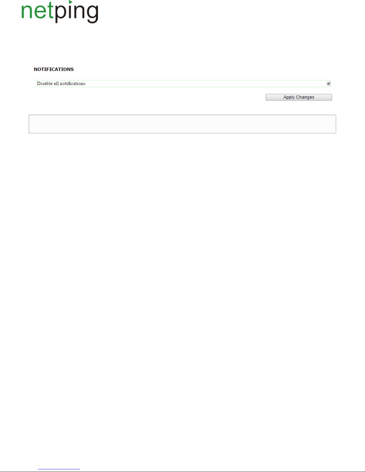
It is possible to disable all notification types at the page « » of a device web interface. To do this, there is a need to check a checkbox «Setup Disable all
» and click the button « »:notifications Apply changes
The setting « » does not disable notifications sent to the log file and SYSLOG.Disable all notifications
Copyright © NetPing east Co., Ltd E-mail: Phone:+886-2-23121582[email protected]
Page 37
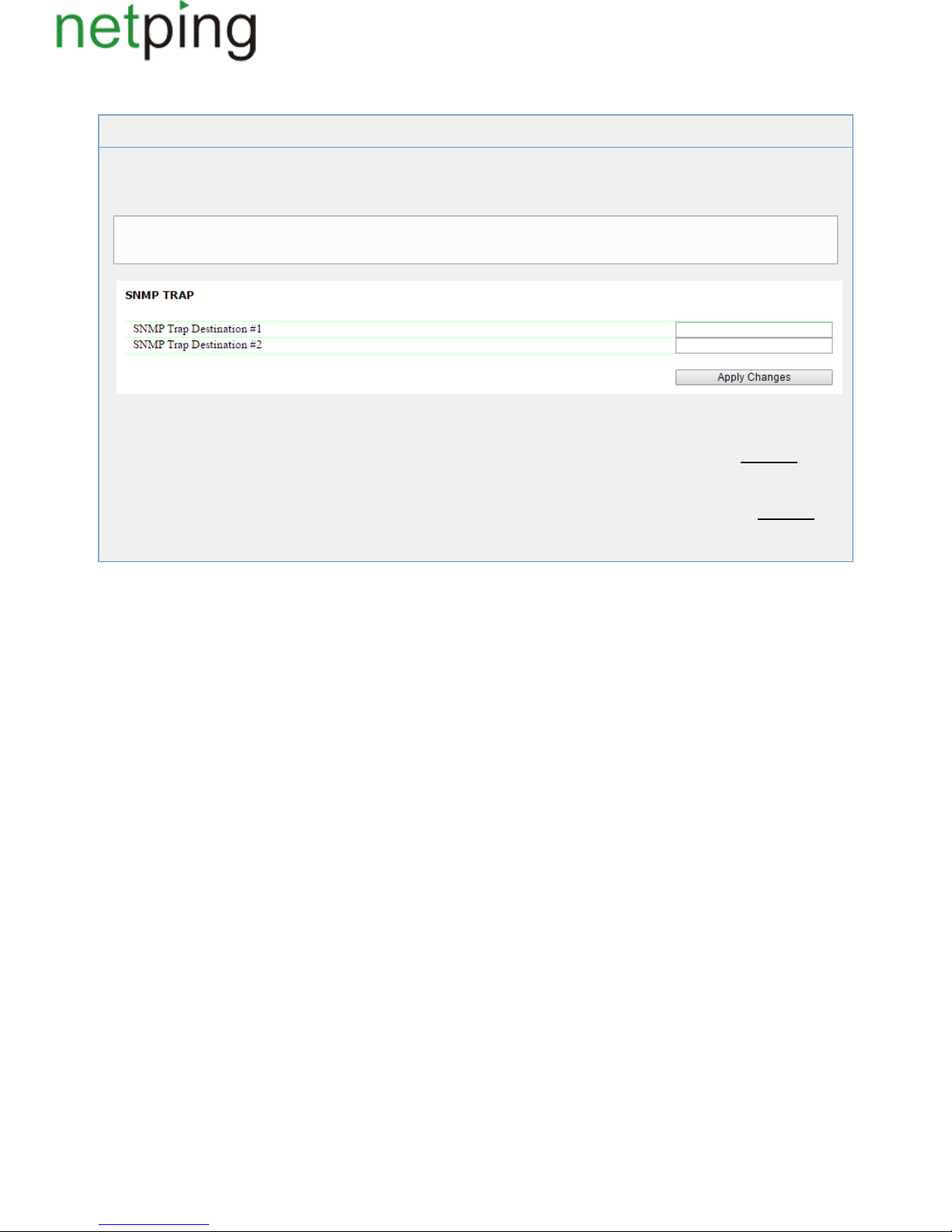
[ENG] 3.7. [DKSF 48.4 IU] It Is Necessary to Send SNMP Trap Notifications. How to Configure This?
_D_E_SNMP_Trap
IP addresses for sending SNMP TRAP notifications are configured at the page « » of a device webSetup
interface. This group of settings allows configuring up to two addresses, where SNMP TRAP notifications
will be sent via an SNMP protocol.
In the section « » it is possible to configure the following:SNMP TRAP
SNMP Trap Destination #1- is a field for configuring or changing the first address, where SNMP TRAP notifications will be sent. It is
possible to specify an IP address or a domain name. An empty field means SNMP TRAP notifications will not be sent.On default:addre
ss is not specified
SNMP Trap Destination #2 – is a field for configuring or changing the second address, where SNMP TRAP notifications will be sent. It
is possible to indicate an IP address or a domain name. An empty field means SNMP TRAP notifications will not be sent.On default:аd
dress is not specified
After configuring all necessary settings, click the button « ».Apply changes
Events for these notifications to be sent are specified at other pages of a device web interface.
Copyright © NetPing east Co., Ltd E-mail: Phone:+886-2-23121582[email protected]
Page 38
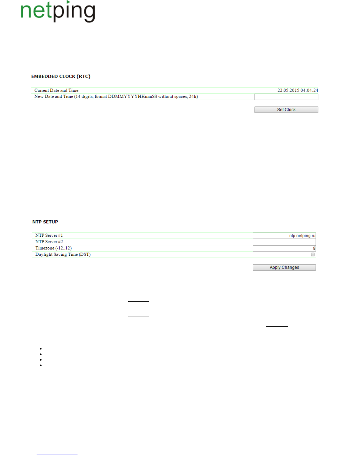
[ENG] 3.8. [DKSF 48.4 IU] How to Set the Clock?
Setting the Clock Manually
To set the clock manually, there is a need to go to the page « » of a device web interface:Setup
In the section « » it is possible to view and set up the following:Embedded Clock (RTC)
Current Date and Time –is a field for viewing a current time.
New Date and Time (14 digits, format DDMMYYYYHHmmSS without spaces) –is a field for setting a clock manually.
After the clock is set, click the button « ».Set Clock
Time Synchronization with External NTP Servers
There is a need to go to the page « » of a device web interface to set up a synchronization with external NTP servers.Setup
This group of parameters allows setting NTP servers (time servers) for a device. A device will set and adjust its internal clock according to them. It is
possible to set up to two NTP servers. If the first NTP server is unavailable, a device will try to synchronize time using the second NTP server. It is
possible to check a correctness of a configuration by generating an event and viewing its time log, in a log file at the page «Log».
In the section « » it is possible to configure the following:NTP Setup
NTP Server #1 is a field to view or change the address of the first NTP server. It is allowed to indicate an IP address or a domain name. An empty–
field disables the feature of a time synchronization.On default:address is not specified
NTP Server #2 is a field to view or change the address of the second NTP server. It is allowed to indicate an IP address or a domain name. An empty–
field disables the feature of a time synchronization.On default:address is not specified
Timezone–is a field to view or change a local timezone. A positive or a negative number of offset hours from UTC is set. On default: 3
You are welcome to use freely available NTP servers on the Internet as NTP servers, for example, the ones from ,http://www.pool.ntp.org/en/
particularly:
0.europe.pool.ntp.org
1.europe.pool.ntp.org
2.europe.pool.ntp.org
3.europe.pool.ntp.org
A device must have a properly configured gateway and an Internet connection via an NTP protocol to use NTP servers from the Internet.
After setting up all necessary parameters, click the button « ».Apply changes
Copyright © NetPing east Co., Ltd E-mail: Phone:+886-2-23121582[email protected]
Page 39
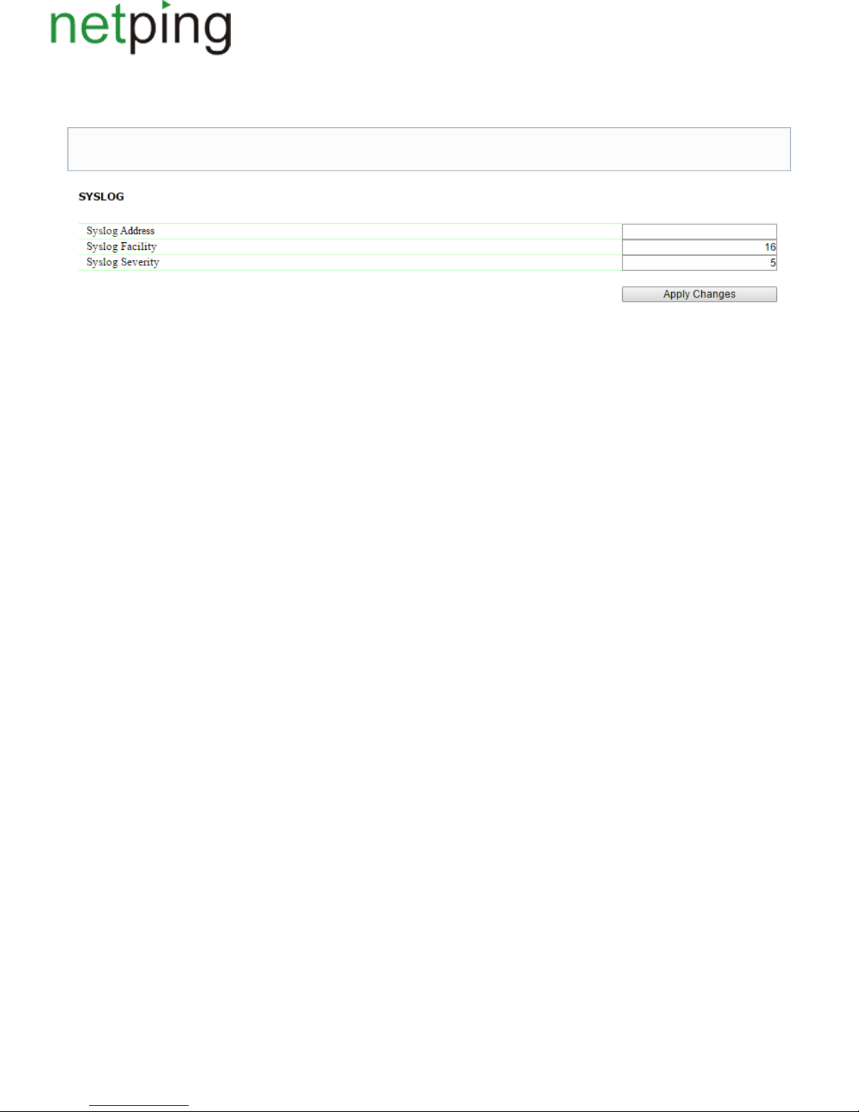
[ENG] 3.9. [DKSF 48.4 IU] I Want to Configure SYSLOG. How to Do This?
Transfer of notifications to the SYSLOG server is configured at the page « » of a device web interface.Setup
In the section « » it is possible to configure the following:SYSLOG
SysLogAddress–is an IP address of the SYSLOG server. A log file of a device will be duplicated completely on the SYSLOG server.
Syslog Facility – is a type of programs, for which logging is maintained.
Syslog Severity – indicates the urgency of notifications (from emergency to debugging).
After setting up all necessary parameters, click the button « ».Apply changes
Events, according to which these notifications will be sent, are set at other pages of a device web interface.
Copyright © NetPing east Co., Ltd E-mail: Phone:+886-2-23121582[email protected]
Page 40
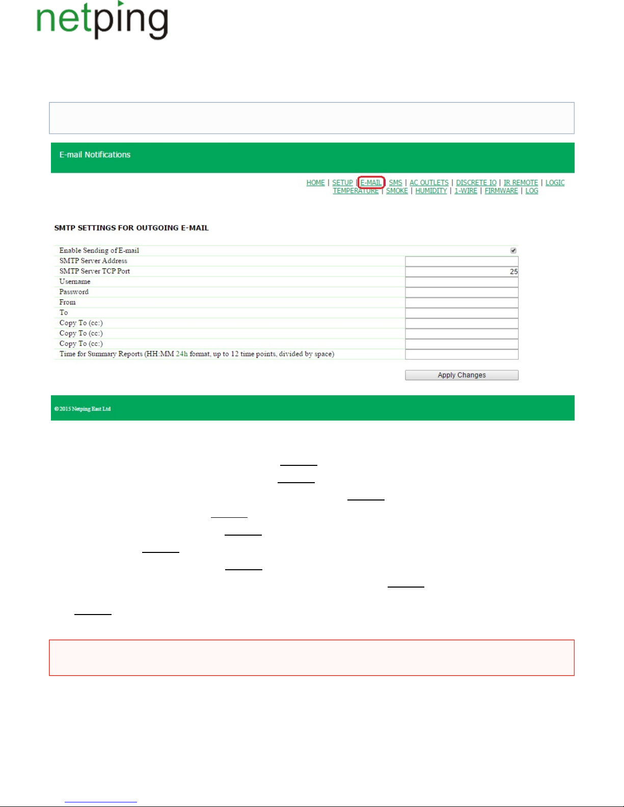
[ENG] 3.10. [DKSF 48.4 IU] How to Receive Notifications and Reports via Email?
To configure the module for sending e-mail notifications and reports about a status, there is a need to go to the page « » of a web interface.TheE-MAIL
equipment sends notifications using an SMTP protocol.
where:
when unchecking the checkbox a device will not send e-mail notifications. This was designed, first of all, to handleEnable Sending of E-mail –
maintenance in a server room, as well as the one of the equipment.On default:checkbox is not checked
is an email address for an incoming mail.SMTP Server Address – On default:empty line
is an email server port, which works via an SMTP protocol.SMTP Server TCP Port – On default: 25
is a username of an SMTP server.Username – On default:empty line
is a password of an SMTP server user.Password – On default:empty line
a sender's address.From– On default:empty line
a destination address for e-mail notifications.To – On default:empty line
addresses of secondary recipients for e-mail notifications, to whom a copy is sent.Copy To (сс:) – On default:empty line
is a time when reports on a status of sensors viaTime for Summary Reports (HH:MM 24h format, up to 12 time points, divided by space) – will be sent
e-mail.On default:empty line
After setting the parameters, click the button «Apply changes».
Events, on which e-mail notifications will be sent, are set at other pages of a device web interface.
A device can work only with the mail servers, which support an SMTP protocol and authentication method AUTH PLAIN and AUTH
LOGIN, as well as a method without authentication! At the same time a device cannot support SSL, TLS or another encoding!
Copyright © NetPing east Co., Ltd E-mail: Phone:+886-2-23121582[email protected]
Page 41
1.
2.
3.
4.
5.
[ENG] 3.11. [DKSF 48.4 IU] How to Update Firmware on a Device?
There is a need to do the following to update an embedded firmware version:
Download an up-to-date firmware from the official website of the company (section « »):Files http://www.netpingdevice.com
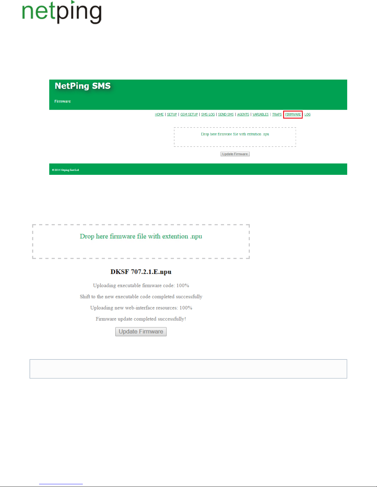
Go to the page « » of a device web interface. You can easily update the firmware of a device from this page without using any specificFirmware
software. To do that, you will need a browser supporting HTML 5 API. Google Chrome or Internet Explorer of the 9th version and higher are
recommended;
Drag a firmware file to the indicated page area;
Wait until a firmware file is copied to a device
Click the button «Update Firmware»
Wait for the message on a successful operation completion:
Retry if an updating process was interrupted. A web interface (pages « », « », « ») will be available even if the firmware was notHome Setup Firmware
successfully updated.
Certain system settings may be changed after updating. Do not forget to check the most important operation parameters.
Copyright © NetPing east Co., Ltd E-mail: Phone:+886-2-23121582[email protected]
Page 42
[ENG] 3.12. [DKSF 48.4 IU] What Notifications Has the Log File Got?
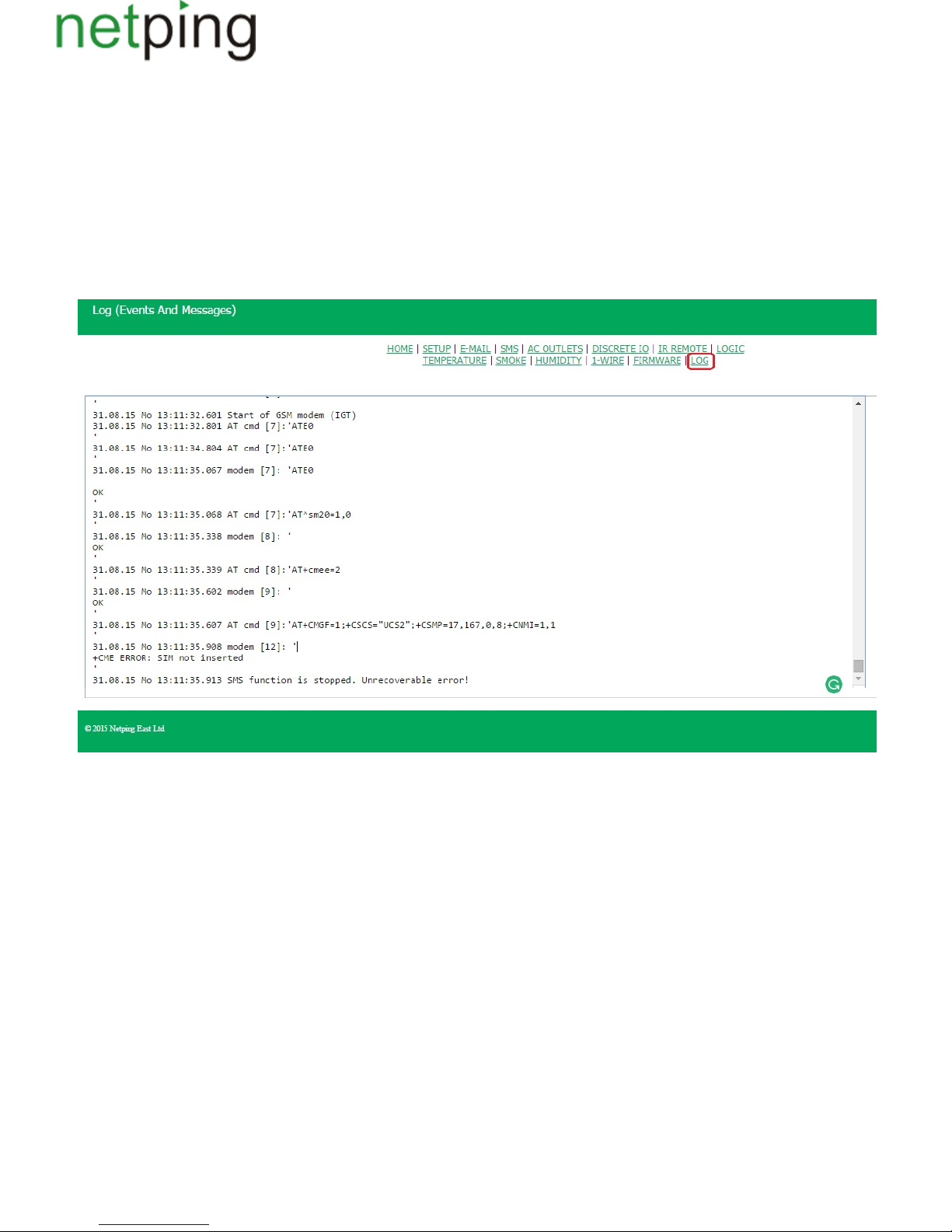
The page of a web interface represents a device operation. In the log file events of a device are recorded in a chronological order.All«LOG»
notifications of the log file are duplicated via SYSLOG protocol, if an IP address of the SYSLOG server is specified in the settings of a device.
A log file is located in a nonvolatile memory. There are approximately 220 - 350 last notifications stored in the memory. All notifications are rewritten
round, which means that the oldest notification in the log file is rewritten by a new one.
The first time tag in the log file is 01.01.70 Mon 00:00: 00.UTC. If there is an IP address of an NTP server specified in the settings, then a device will try
to get a precise time and in case of success it will synchronize its internal clock with a precise time. After synchronizing time, two records will appear in
the log file that represent a time lapse when adjusting a clock to a precise time. If time received when synchronizing with an NTP server is different from
the time of an internal clock for less than 5 minutes, the clock will not be adjusted. The pace of the internal clock is changed in the way to adjust internal
time with a precise time received from an NTP server in a certain amount of time. Due to this, there is no time lapse in the list of events in the log file,
which makes analyzing it easier.
General Events
Operation Start (Reboot) XXXX YYYY– is recorded into the log file when rebooting or turning a device on. XXXX is a model name of a device.
YYYY is a firmware version ., installed on a device
Adjusting......the Clockis recorded into the log file if a time via an NTP protocol is more than 5 minutes different from the time set on thereceived
internal clock. The notification is displayed in 2 lines. The first line represents a time tag before resetting the internal clock while the second line
represents a time tag right after resetting the internal clock.
Events from IO Lines
ION=Y XXXX–is recorded into the log file when a current logic level is being changed at the IO line (switching from the status «0» to the status «1»
and vice versa) when notifications from the IO line are enabled in the log file. N is a number of an IO line. Y is a current logic level of an IO line. XXXX
is a description of an IO line, specified by a user at the page of a web interface.
Events from Temperature Sensors
Thermo: channel N "XXXX" , normal(AA )YYC ..BBC – is recorded into the log file when readings of a temperature sensor are within the limits of the
N is a number of a channel of a temperature sensor.range specified by a user when notifications from a temperature sensor are enabled in the log file.
XXXX is a description of a temperature sensor, specified by a user at the page of the web interface. YY – are readings of a current temperature in . °C A
Ais a lower limit of a temperature range in °C. BB – is an upper limit of a temperature range in °C.
Copyright © NetPing east Co., Ltd E-mail: Phone:+886-2-23121582[email protected]
Page 43

Thermo: channel N "XXXX" , above normalYYC (AA )..BBC – is recorded into the log file, when readings of a temperature sensor are above the limits
of a specified range set by a user . N – is a number of a channel of a temperaturewhen notifications from a temperature sensor are enabled in the log file
sensor. XXXX – is a description of a temperature sensor, specified by a user at the page of a web interface. YY are readings of a current temperature in
°C. AAis a lower limit of a temperature range in °C. BB – is an upper limit of a temperature range in °C.
Thermo: channel N "XXXX" , below normal YYC (AA )..BBC – is recorded into the log file when readings of a temperature sensor are below the limits
of a range specified by a user . N – is a number of a channel of a temperaturewhen notifications from a temperature sensor are enabled in the log file
sensor. XXXX – is a description of a temperature sensor, specified by a user at the page of a web interface. YY – are readings of a current temperature
in °C. AA– is a lower limit of a temperature range in °C. BB – is an upper limit of a temperature range in °C.
Thermo: channel N "XXXX" - there is no sensor or it is faulty – is recorded into the log file when a temperature sensor does not respond (is not
connected) . when notifications from a temperature sensor are enabled in the log file N – is a number of a channel of a temperature sensor. XXXX – is a
description of a temperature sensor, specified by a user at the page of a web interface.
Events from a Humidity Sensor
Humidity XX%, normal (YY..ZZ%)– is recorded into the log file when readings of a humidity sensor are within the limits of a range specified by a user
when notifications from a humidity sensor are enabled in the log file. XX – are readings of a relative humidity in %. YYis a lower limit of a normal
humidity in %. ZZ – is an upper limit of a normal humidity range in %.
Humidity XX%, above normal (YY..ZZ%)– is recorded into the log file when readings of a humidity sensor are above the limits of a range specified by
a user . XX – are readings of a relative humidity in %. YYis a lower limit of awhen notifications from a humidity sensor are enabled in the log file
normal humidity range in %. ZZ is an upper limit of a normal humidity range in %.
Humidity XX%, below normal (YY..ZZ%)– is recorded into the log file when readings of a humidity sensor are below the limits of the range specified
by a user . XX – are readings of a relative humidity in %. YY– is a lower limit of awhen notifications from a humidity sensor are enabled in the log file
normal humidity range in %. ZZ – is an upper limit of a normal humidity range in %.
Humidity - there is no sensor or it is faulty – is recorded in the log file when a humidity sensor does not respond (is not connected) when notifications
.from a humidity sensor are enabled in the log file
Events from Smoke Sensors
Smoke sensor N "XXXX" switched to the status "YYYY" – is recorded into the log file when a status of a smoke sensor is being changed when
notifications from a smoke sensor are enabled in the log file. X – is a channel number of a smoke sensor. XXXX is a description of a channel of a smoke
sensor, which is specified by a user at the page of a web interface. YYYY is a name of a current status of a smoke sensor. The next statuses are possible:
«Normal», «ALARM», «Off», «Failure».
Events of the Module «Watchdog»
Watchdog: resetting a channel N"XXXX". A (IPA)YYYY, B (IPB)YYYY, C (IPC)YYYY– is recorded into the log file when the module Watchdo«
g . N – is a number of a power management channel. XXXX –is a description of a power management channel, which is specified by a user» is triggered
at the page of a web interface. IPA, IPB, IPC – IP addresses specified by a user in the settings of the module «Watchdog» are substituted. YYYY – is a
status, corresponding to a requested IP address. The next statuses are possible: , , .«responds» «silent» «ignored»
Watchdog: channel N "XXXX" - a limit of repeated resets is over (Y). Resets are paused.– is recorded into the log file if in the mode of the module
«Watchdog» a limit for the number of consequent resets of a connected device is reached. N – is a number of a power management channel. XXXX - is
a description of a power management channel, specified by a user at the page of a web interface. Y – is a number of consequent resets of a connected
.device
Watchdog: channel N "XXXX" reset - a response is received. Reset pause is over.– is recorded into the log file if a response from the module «Watchdo
resets are paused after a specified limit is reached. g» is received in the status when «Wathdog» signals a reset of reboots and a start of a normal
.functioning of the watchdog according to a usual algorithm
Events of the Module «Schedule»
Schedule N switched to the status YYYY – is recorded into the log file when the module . «Schedule» is triggered N is a number of a power management
channel. YYYY – is a status of an embedded relay. The next statuses are possible: on , .« » «off»
Events from Embedded Relays
PWR: relay N "XXXX" YYYY – is recorded into the log file when an embedded relay was triggered. N – is a number of a power management channel.
XXXX –is a description of a power management channel, specified by a user at the page of a web interface. YYYY is a status of an embedded relay.
The next statuses are possible: , .«switched on» «switched off»
PWR: relay N "XXXX" is switched to the mode "YYYY" through the web interface – is recorded into the log file when a relay management mode is swi
through atched device web interface. N – is a number of a power management channel. XXXX –is a description of a power management channel,
specified by a user at the page of a web interface. YYYY – is a name of a relay management mode. The next modes are possible: «switched off manually
Copyright © NetPing east Co., Ltd E-mail: Phone:+886-2-23121582[email protected]
Page 44

, » «switched on manually , » «watchdog management , » «schedule management , » «schedule and watchdog management , » «logic management .»
PWR: relay N "XXXX" is switched to the mode "YYYY" through SNMP– is recorded into the log file when a relay management mode is switched
using an SNMP protocol. N – is a number of a power management channel. XXXX –is a description of a power management channel, specified by a
user at the page of a web interface. YYYY – is a name of a relay management mode. The next modes are possible: «switched off manually», «switched
on manually», «watchdog management», «schedule management», «schedule and watchdog management», «logic management».
PWR: relay N "XXXX" "YYYY" by running is switched to the mode cgi– is recorded into the log file when usinga relay management mode is switched
URL-encoded commands (HTTP API). N – is a number of a power management channel. XXXX is a descriptionof a power management channel,
specified by a user at the page of a web interface. YYYY – is a name of a relay management mode. The next modes are possible: «switched off
manually», «switched on manually», «watchdog management», «schedule management», «schedule and watchdog management», «logic management».
PWR: relay N "XXXX" is switched to the mode "YYYY" by a command via SMS– is recorded into the log file when switching a relay management
mode using SMS commands. N – is a number of a power management channel. XXXX –is a description of a power management channel, specified by
a user at the page of a web interface. YYYY – is a name of a relay management mode. The next modes are possible: «switched off manually», «switched
on manually», «watchdog management», «schedule management», «schedule and watchdog management», «logic management».
Events from Power Supply Inputs
PWR: sockets N are switched to the input X – is recorded into the log file when an input for a group of sockets is switched directly. N – is a group of
sockets with the next possible values: «1-4» and «5-8». X – is a number of an input, possible values are «1» and «2».
PWR: N sockets via a web interfacean input X without backup is set to feed – is recorded into the log file when installing the main input for a group of
sockets via a device web interface as well as in the moment of disabling a parameter . N – is a group of sockets. The next«Switch to the backup input»
values are possible: «1-4» and «5-8». X – is an input number, its possible values are: «1» and «2».
– is recorded into the log file in the moment of disabling thePWR: to feed N sockets using an SMS commandan input X without the backup is set
parameter «Switch to the backup input . N – is a group of sockets. The next values are possible: «1-4» and «5-8». X – » using an SMS command is an
: «1» and «2».input number, its possible values are
PWR: a N sockets via a web interface, backup without auto return main input X is set to feed – is recorded into the log file in the moment of setting the
parameter . «Switch to the backup input» in a web interface N – is a group of sockets. The next values are possible: «1-4» and «5-8». X – is an input
number, its possible values are: «1» and «2».
PWR:a main input X is set to feed N sockets using an SMS command, backup without auto return– is recorded into the log file in the moment of
setting the parameter «Switch to a backup input»using an SMS command. N – is a group of sockets. The next values are possible: «1-4» and «5-8». X –
is an input number, its possible values are: «1» and «2».
PWR:a main input X is set to feed N sockets via a web interface, backup with an auto return– is recorded into the log file in the moment of setting the
parameter «Autoreturn to a main input»in a web interface. N – is a group of sockets. The next values are possible: «1-4» and «5-8». X – is an input
number, its possible values are: «1» and «2».
PWR: a main input X is set to feed – is recorded into the log file in the moment of setting N sockets using an SMS command, backup with auto return
the parameter«Autoreturn to a main input» using an SMS command. N – is a group of sockets. The next values are possible: «1-4» and «5-8». X – is an
input number, its possible values are: «1» and «2».
PWR: a command to return Nsockets to a main input (X) is received via a web interface – is recorded into the log file in the moment of a manual return
to a main input in a device web interface. N – is a group of sockets. The next values are possible: «1-4» and «5-8». X – are input numbers, possible
values are: «1->2» and «2->1».
PWR: a command to return N sockets to a main input (X) is received using an SMS command– is recorded into the log file in the moment of a manual
return to a main input using an . N – is a group of sockets, the next values are possible: «1-4» and «5-8». X – are input numbers, possibleSMS command
values are: «1->2» and «2->1».
– is recorded into the log file in the moment of a manual return toPWR: a command to return N sockets to a main input (X) is received by running cgi
a main input by . URL-encoded commands (HTTP API) N – is a group of sockets, the next values are possible: «1-4» and «5-8». X – are input numbers,
possible values are: «1->2» and «2->1».
PWR: voltage appeared at the input X– is recorded into the log file when a voltage appeared at the input X of a device. X – is an input number,
possible values are: «1» and «2».
PWR: voltage disappeared at the input X– is recorded into the log file when a voltage disappeared at the input X of a device. X – is an input number,
possible values are: «1» and «2».
Events from the Module for Sending E-mail Notifications
sendmail:YYYY received in response to XXXX – is recorded into the log file if a server returns «incorrect» response code. XXXX – is a service
information: an authentication method or a message recipient. YYYY – is an error notification.
sendmail: email discarded – is recorded into the log file if it is impossible to send e-mail notification to an SMTP server.
Copyright © NetPing east Co., Ltd E-mail: Phone:+886-2-23121582[email protected]
Page 45

No room for new mail message XXXX – is recorded into the log file if notification queue is overflown. XXXX – is a client's request and a server's
.response
Events of GSM Modem Operation
Manual restart of a GSM modem through a web interface– is recorded into the log file in the moment of running a procedure of a manual reloading a
GSM modem by a user in a device web interface.
GSM modem is ready for operation– is recorded into the log file after a GSM modem has been initialized in the system.
When a parameter «Register exchange with a GSM modem to the log is enabled at the page of a device web interface, a large amount of» «SMS»
debugging information about a GSM modem operation will be displayed in the log file: AT-commands, responses to AT commands, operation errors
and a modem status.
SYSLOG Support
All notifications in the log are duplicated by sending notifications via a SYSLOG protocol, if SYSLOG server addresses are specified in the settings of a
device at the page of a«Setup» web interface.
SYSLOG server is convenient to be used for a centralized collecting of notifications on events, taking place at numerous devices and computers,
working in the network, particularly, on events at Netpingdevices.
Copyright © NetPing east Co., Ltd E-mail: Phone:+886-2-23121582[email protected]
Page 46

[ENG] 4. [DKSF 48.4 IU] Working with Temperature Sensors
Copyright © NetPing east Co., Ltd E-mail: Phone:+886-2-23121582[email protected]
Page 47
[ENG] 4.1. [DKSF 48.4 IU] What Temperature Sensors a Device Supports?
A device supports 1-Wire temperature sensors.
To plug a 1-Wire temperature sensor, there is a need to link its unique number to the sensor X in the field « » at the page «Unique number of 1W sensor
». You can know a unique number of a 1-Wire sensor after reading the section TEMPERATURE SENSORS «4.2. [DKSF 48.4] How to Determine a
».Unique Number of a 1-Wire Sensor?
Temperature values and temperature sensor statuses are updated automatically approximately four times a minute with no need to reload a web page
manually.
It is possible to plug up to 8 temperature sensors to a device.
A device does not support TS and WT temperature sensors.
Copyright © NetPing east Co., Ltd E-mail: Phone:+886-2-23121582[email protected]
Page 48
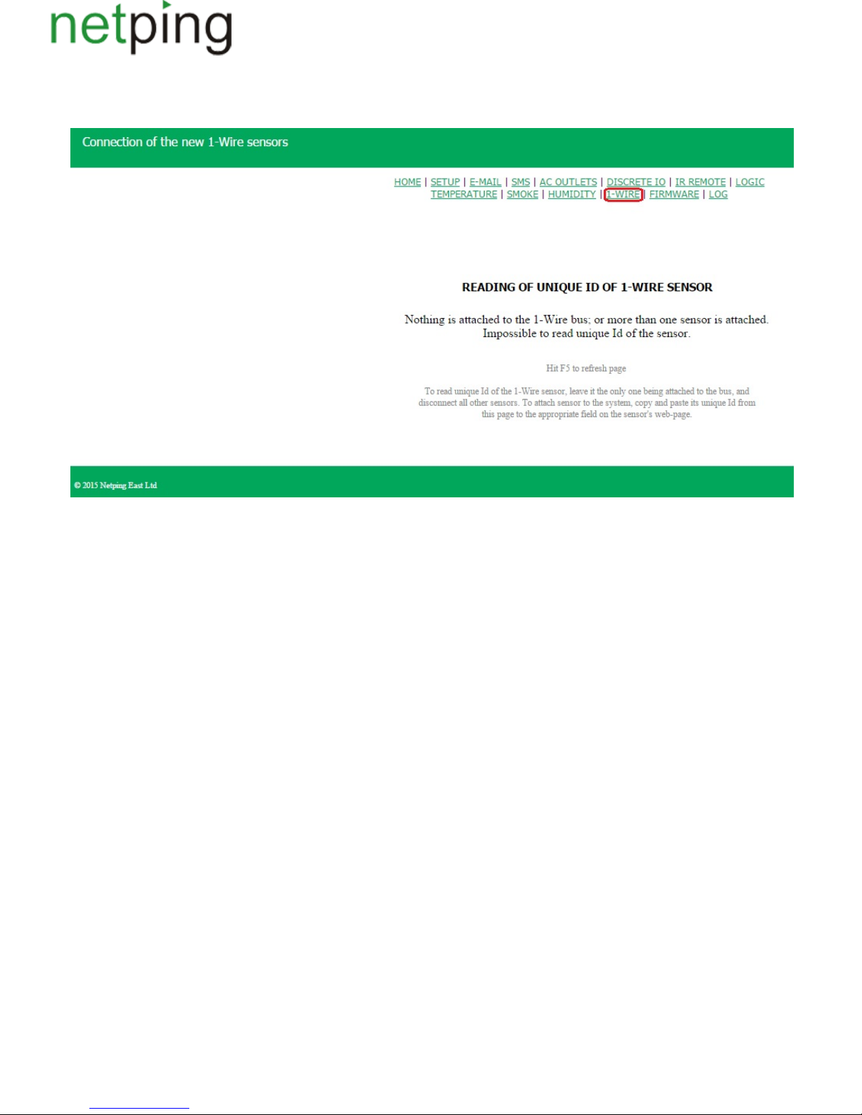
1.
2.
3.
[ENG] 4.2. [DKSF 48.4 IU] How to Determine a Unique Number of a 1-Wire Sensor?
To read a unique Id of a 1-Wire sensor, there is a need to go to the page « » of a device web interface:1-WIRE
To determine a unique Id using a web interface, there is a need to do as follows:
Unplug all 1-Wiresensors from a device;
Plug a sensor, which unique number you want to know to a device;
Go to the address or go to the page « » of a web interface. A unique Id of a sensor will behttp://<ip_address_of_a_device>/ow_new.cgi 1-WIRE
displayed in the browser window.
A unique number of a 1-Wiresensor looks like the following (16hexadecimal digits:2818 0ea2 0600 0039 0..9,a..f).
To plug a 1-Wire sensor, copy its unique number from this page to a corresponding field at the page of a web interface.
Copyright © NetPing east Co., Ltd E-mail: Phone:+886-2-23121582[email protected]
Page 49
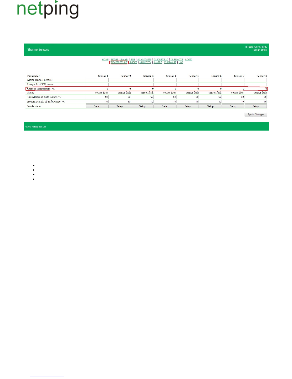
[ENG] 4.3. [DKSF 48.4 IU] Where to Read a Current Temperature?
To see a current temperature of temperature sensors, there is a need to go to the page « » of a device web interface:TEMPERATURE
Temperature values and sensor statuses are updated automatically not less than four times a minute with no need to reload a page manually.
Current Temperature, °C– displays a current temperature of a sensor in degrees of Celcius. A temperature value is automatically updated from time to
time without reloading a web page.
Status – displays a current status of a temperature sensor. Possible values are:
Failure– a temperature sensor is not connected or does not respond;
Normal– a temperature sensor responds, and a temperature value is within the limit of a specified range for this temperature sensor;
Above normal– a temperature sensor responds, and a temperature value is above a specified range for this temperature sensor;
Below normal– a temperature sensor responds, and a temperature value is below a specified range for this temperature sensor.
Copyright © NetPing east Co., Ltd E-mail: Phone:+886-2-23121582[email protected]
Page 50
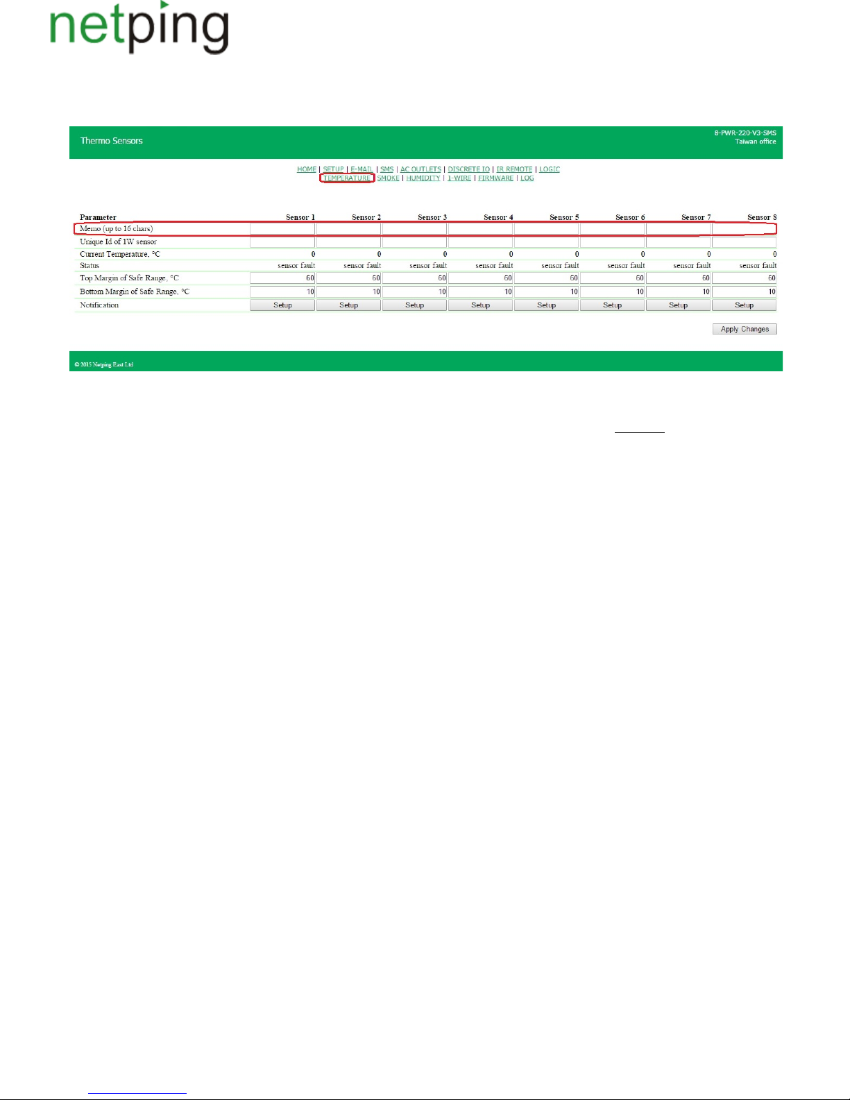
[ENG] 4.4. [DKSF 48.4 IU] Is It Possible to Set a Description for Temperature Sensors?
To set a description for temperature sensors, there is a need to go to the page « » of a device web interface:TEMPERATURE
A description for temperature sensors is set in the field « ».Memo
Memo – is a field for setting a brief description of a temperature sensor. A memo is used in SYSLOG and log notifications, and is also included into
SNMP TRAP, SMS, e-mail notifications, email reports about a status of sensors. Its maximum size is 16 characters.On default: empty line
After changing the settings, there is a need to save the parameters by clicking the button « ».Apply changes
Copyright © NetPing east Co., Ltd E-mail: Phone:+886-2-23121582[email protected]
Page 51
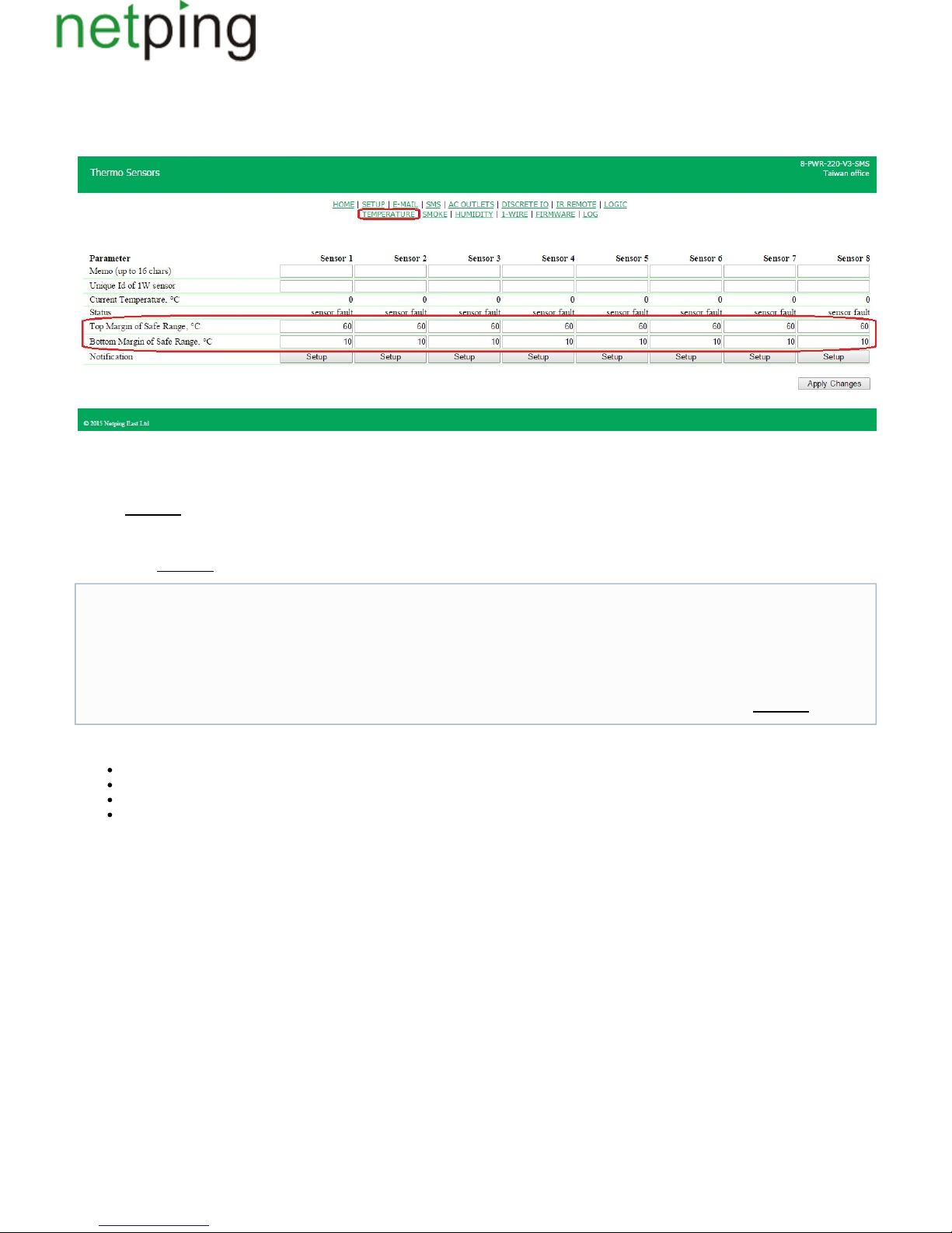
[ENG] 4.5. [DKSF 48.4 IU] Configuring Top and Bottom Margin of a Safe Range for a Temperature Sensor
To configure a top and bottom margin of a safe range for a temperature sensor, there is a need to go to the page « » of a device webTEMPERATURE
interface:
where:
Top Margin of Safe Range, °C– is a field for setting a top margin of a temperature range for each temperature sensor. A temperature range is used to
specify conditions for generating SNMP TRAP and Syslog notifications as well as e-mail and SMS notifications (in a device with an embedded GSM
modem). : 60On default
Bottom Margin of Safe Range, °C– is a field for setting a bottom margin of a temperature range for each temperature sensor. A temperature range is
used to specify conditions for generating SNMP TRAP and Syslog notifications as well as e-mail and SMS notifications (in devices with an embedded
GSM modem). : 10On default
Status – displays a current status of a temperature sensor. Its possible values are:
Failure– a temperature sensor is not connected or does not respond;
Normal– a temperature sensor responds and a temperature value is within the margins of a specified range for this temperature sensor;
Above normal- a temperature sensor responds, and a temperature value is above a specified range for this temperature sensor;
Below normal- a temperature sensor responds, and a temperature value is below a specified range for this temperature sensor
After changing the settings, there is a need to save the parameters by clicking the button « ».Apply changes
To prevent frequent triggering of a top and bottom margins, a switching hysteresis of .1°C is used
A hysteresis sets a «corridor» around a specified temperature, within the limits of which top and bottom margins of a safe range do not
respond to temperature oscillations. This feature allows to avoid frequent random notifications from a temperature sensor caused by natural
spontaneous oscillations of a temperature measured by a sensor. If a current status of a temperature sensor is «above normal», then a
threshold for switching a status is a specified temperature minus a hysteresis value. And vice versa, if a current status is «below normal», then
a threshold for switching is a specified temperature plus a hysteresis value. As soon as a temperature increases or decreases reaching a
threshold value (taking a hysteresis into account), thus leaving margins of a «corridor», a temperature status is changed. : 1On default
Copyright © NetPing east Co., Ltd E-mail: Phone:+886-2-23121582[email protected]
Page 52
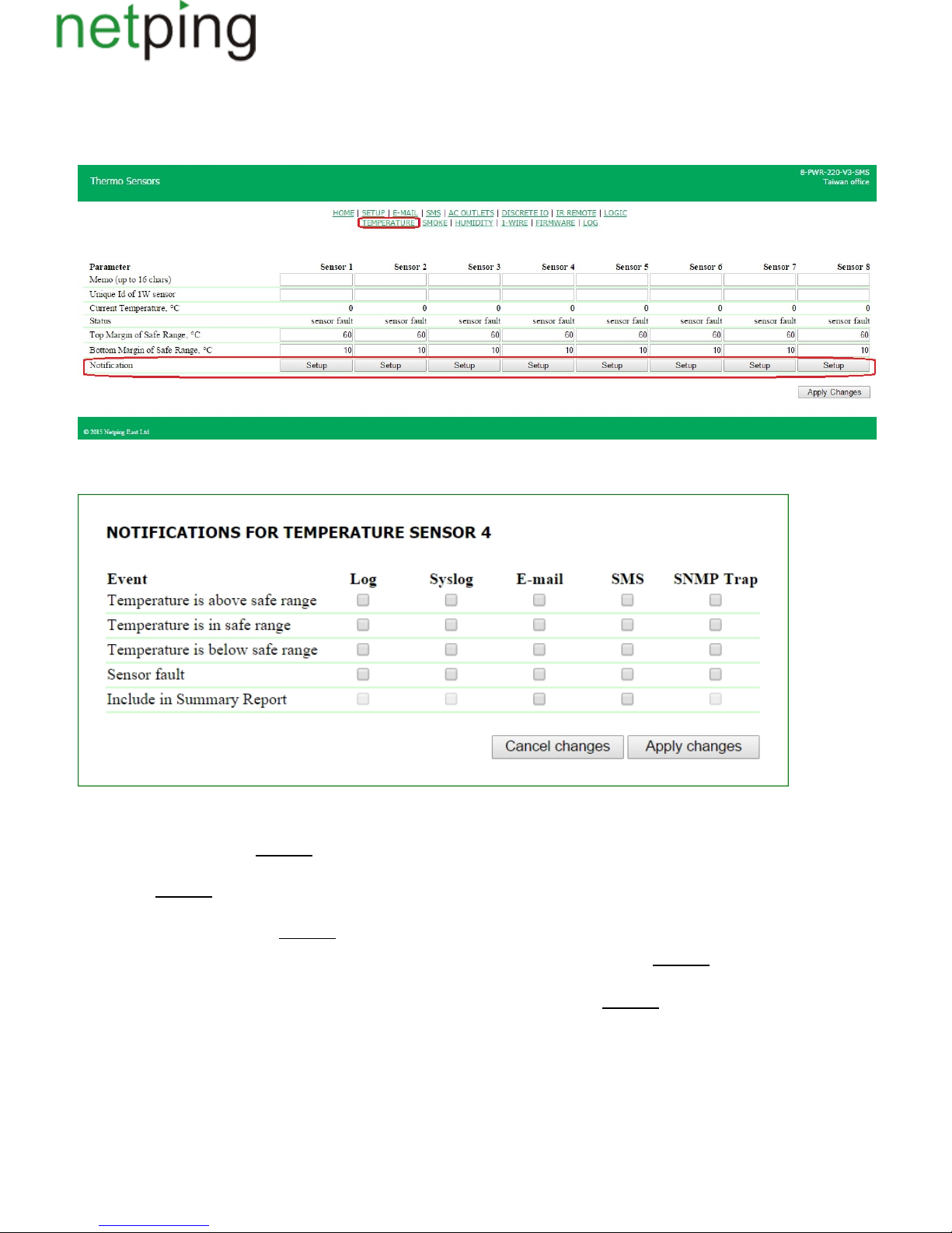
[ENG] 4.6. [DKSF 48.4 IU] I Want to Configure Sending Notifications When a Status of a Temperature Sensor Is
Changed. How to Do This?
Sending notifications when a status of a temperature sensor is changed, is configured at the page « »of a device web interface:TEMPERATURE
When clicking the button « » a menu of settings is displayed for sending notifications of the following types: Log, Syslog, E-mail, SMS (inConfigure
devices with an embedded GSM modem) and SNMP Trap:
where:
Temperature is above safe range– is a checkbox, when checked a device will send notifications if a current temperature is above a top margin of a safe
range for this temperature sensor. : checkbox is not checkedOn default
Temperature is in safe range– is a checkbox, when checked a device will send notifications if a current temperature is back to margins of a safe range
for this sensor. : checkbox is not checkedOn default
Temperature is below safe range– is a checkbox, when checked a device will send notifications if a current temperature is below a bottom margin of a
safe range for this temperature sensor. : checkbox is not checkedOn default
Sensor fault– is a checkbox, when checked a device will send notification if a connection with a sensor is lost. : checkbox is not checkedOn default
Include in Summary Report –is a checkbox when checked reports about a sensor status will be sent via e-mail and/or SMS (in a device will an
embedded GSM modem). Time of sending reports is indicated at the pages « » and « ». SMS E-MAIL : checkbox is not checkedOn default
After setting all necessary parameters, click the button .«Apply changes»
Copyright © NetPing east Co., Ltd E-mail: Phone:+886-2-23121582[email protected]
Page 53

[ENG] 5. [DKSF 48.4 IU] Working with a Humidity Sensor
Copyright © NetPing east Co., Ltd E-mail: Phone:+886-2-23121582[email protected]
Page 54
[ENG] 5.1. [DKSF 48.4 IU] What Humidity Sensor a Device Supports?
A device supports connecting a 1-Wire humidity sensor.
To connect a 1-Wire humidity sensor, there is a need to link its unique number in the field « » at the page «Unique Number of a 1W Sensor HUMIDITY
». You can know a unique number of a 1-Wire sensor after reading the sectionSENSOR «5.2. [DKSF 48.4 IU] How to Determine a Unique Id of a
».1-Wire Humidity Sensor?
Relative humidity values, as well as a humidity sensor status, are updated automatically with no need to reload a web page manually.
It is possible to plug one humidity sensor to a device.
A device does not support a WS humidity sensor.
Copyright © NetPing east Co., Ltd E-mail: Phone:+886-2-23121582[email protected]
Page 55
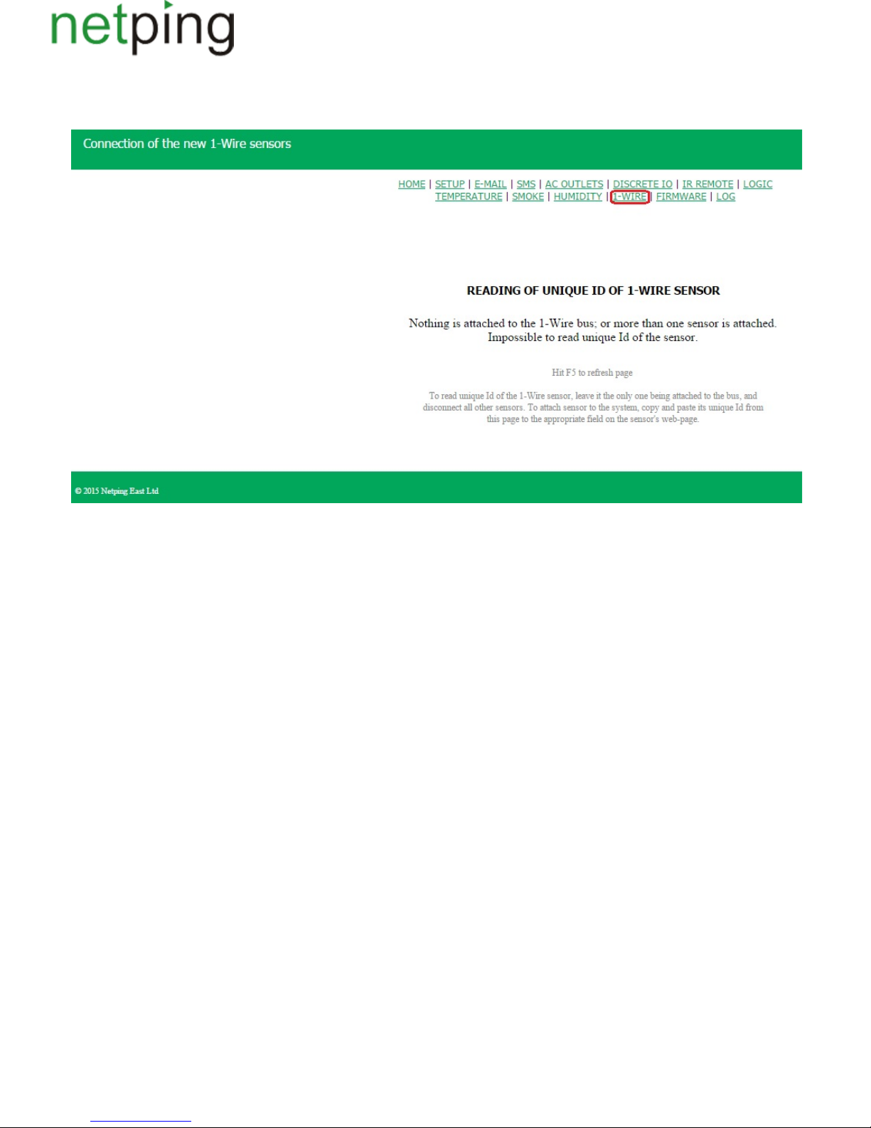
1.
2.
3.
[ENG] 5.2. [DKSF 48.4 IU] How to Determine a Unique Id of a 1-Wire Humidity Sensor?
To read a unique Id of a 1-Wire sensor, there is a need to go to the page « » of a device web interface:1-WIRE
To determine a unique Id using a web interface, there is a need to do as follows:
Unplug all 1-Wiresensors from a device;
Plug a sensor, which unique number you want to know to a device;
Go to the address or go to the page « » of a web interface. A unique Id of a sensor will behttp://<ip_address_of_a_device>/ow_new.cgi 1-WIRE
displayed in the browser window.
A unique number of a 1-Wiresensor looks like the following (16hexadecimal digits:2818 0ea2 0600 0039 0..9,a..f).
To plug a 1-Wire sensor, copy its unique number from this page to a corresponding field at the page of a web interface.
Copyright © NetPing east Co., Ltd E-mail: Phone:+886-2-23121582[email protected]
Page 56
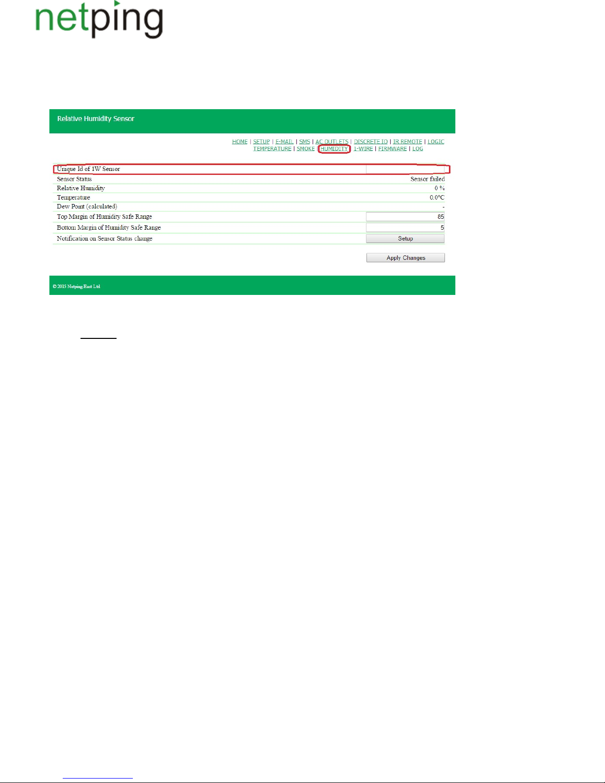
1.
2.
[ENG] 5.3. [DKSF 48.4 IU] Initial Configuration of a Humidity Sensor
At the page « » of a device web interface readings of a humidity sensor are displayed, which is connected to a device. Only one humidityHUMIDITY
sensor of a1-Wire model line can be plugged to a device.
To plug a sensor in, indicate its unique number in the field « .Unique Id of 1W Sensor»
Unique Id of 1W Sensor– is a unique number of a 1-Wire humidity sensor, plugged into a 1W socket. The address consists of 4 four-digit hexadecimal
numbers. : empty lineOn default
You can know a unique Id of a 1-Wire sensor in two ways:
A unique Id of a 1-Wire humidity sensor is indicated on the sticker at the sensor.
You can know a unique Id of a 1-Wire humidity sensor from the section «5.2. [DKSF 48.4 IU] How to Determine a Unique Id of a 1-Wire
»Humidity Sensor?
Copyright © NetPing east Co., Ltd E-mail: Phone:+886-2-23121582[email protected]
Page 57
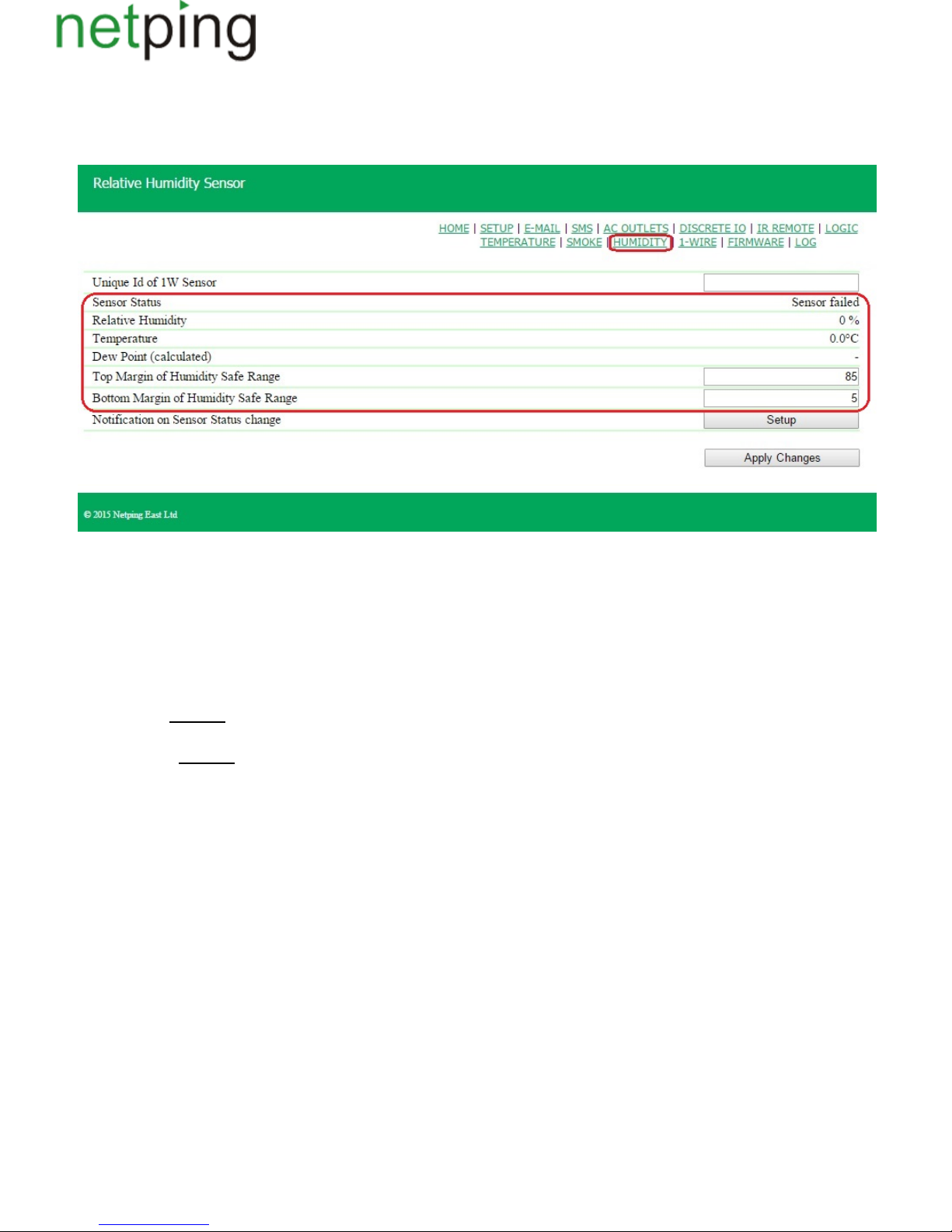
[ENG] 5.4. [DKSF 48.4 IU] Browsing Readings and Configuring Parameters of a Humidity Sensor in a Web
Interface
To browse readings and a configuration of humidity sensor parameters, there is a need to go to the page « »of a device web interface:HUMIDITY
where:
Sensor status – determines a sensor status in a current moment of time. Possible variants are: « », « », «sensor failed within a safe range below a safe range
», « »;above a safe range
Relative Humidity– shows readings of a sensor, which measures a relative humidity in %;
Temperature – shows readings of a temperature sensor, embedded into a humidity sensor, in °C;
Dew Point – is a dew point temperature, which is calculated from readings of a humidity sensor and a temperature, in °C;
Top Margin of Humidity Safe Range– is a humidity value, exceeding which a sensor switches to a status « ». Hysteresis is 1above a safe range ±
percentage point. :85On default
Bottom Margin of Humidity Safe Range– is a humidity value dropping below which a sensor switches to a status « ». Hysteresis is below a safe range ±
1 percentage point. :5On default
Copyright © NetPing east Co., Ltd E-mail: Phone:+886-2-23121582[email protected]
Page 58
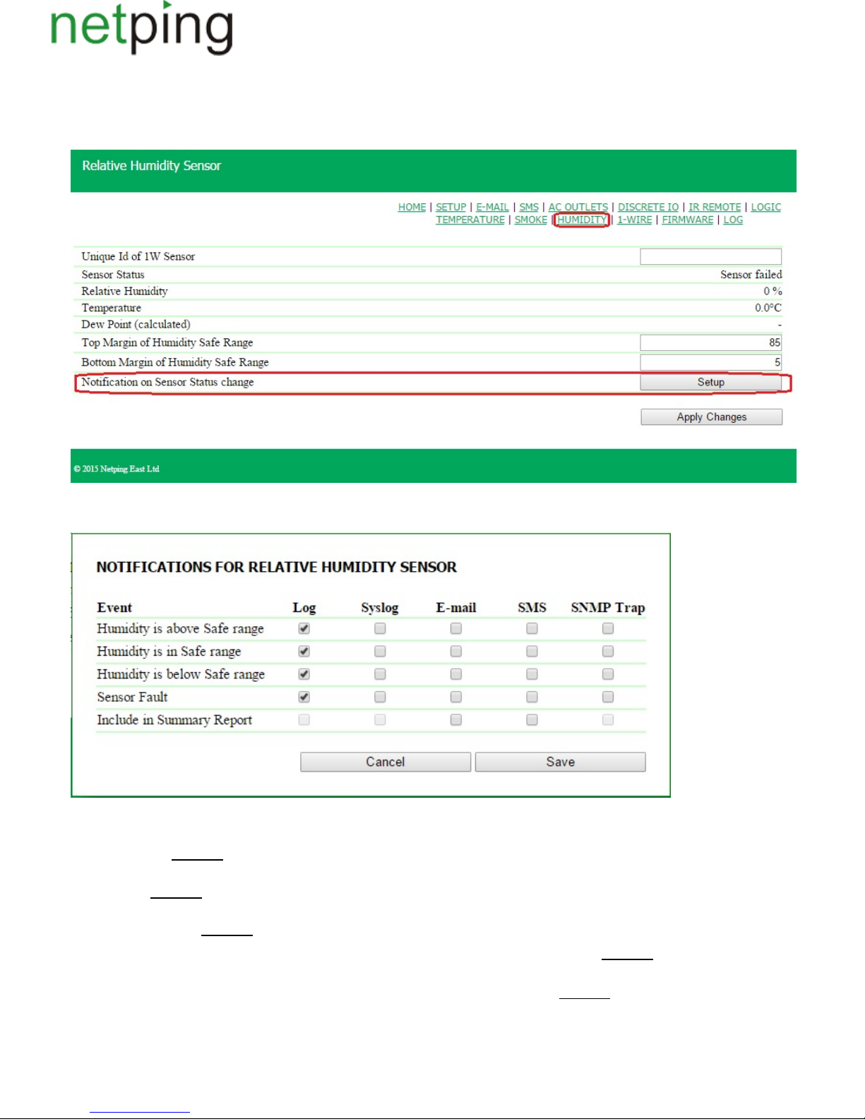
[ENG] 5.5. [DKSF 48.4 IU] I Want to Configure Sending Notifications When a Humidity Sensor Status Is
Changed. How to Do This?
Sending notifications when changing a humidity sensor is configured at the page « »of a device web interface:status of a HUMIDITY
When clicking the button « », a menu of settings appears to configure sending notifications of the next types: Log, Syslog, e-mail, SMS (in a deviceSetup
with an embedded GSM modem) and SNMP Trap:
where:
Humidity is above Safe range– is a checkbox, when checked a device will send notifications if a relative humidity exceeds an upper limit of a safe range
of a humidity sensor. : checkbox is not checkedOn default
Humidity is in Safe range– is a checkbox, when checked a device will send notifications if a relative humidity returns into the limits of a safe range of a
humidity sensor. : checkbox is not checkedOn default
Humidity is below Safe range– is a checkbox, when checked a device will send notifications if a relative humidity dropped below a lower limit of a safe
range of a humidity sensor. : checkbox is not checkedOn default
Sensor Fault– is a checkbox, when checked a device will send notifications if a connection with a sensor is lost. : checkbox is not checkedOn default
Include in Summary Report –is a checkbox, when checked reports about a sensor status will be sent via e-mail and/or SMS (in a device with an
embedded GSM modem).Time for sending reports is configured at the pages « » and « ». SMS E-MAIL : checkbox is not checkedOn default
After setting all necessary parameters, click the button .«Apply changes»
Copyright © NetPing east Co., Ltd E-mail: Phone:+886-2-23121582[email protected]
Page 59

[ENG] 6. [DKSF 48.4 IU] Working with Smoke Sensors
Copyright © NetPing east Co., Ltd E-mail: Phone:+886-2-23121582[email protected]
Page 60
[ENG] 6.1. [DKSF 48.4 IU] What Smoke Sensors a Device Supports?
A device supports connecting 1-Wire smoke sensors.
To connect a 1-Wire smoke sensor, there is a need to link its unique number to the Sensor X in the field « » at the page « ». 1-Wire1W Sensor Id SMOKE
sensor Id can be known from the section« ».4.2. [DKSF 48.4] How to Determine a Unique Number of a 1-Wire Sensor?
Temperature values and temperature sensor statuses are updated automatically with no need to reload a web page manually.
It is possible to connect up to 4 smoke sensors to a device.
A device does not support a .smoke sensor (IP212-141)
Copyright © NetPing east Co., Ltd E-mail: Phone:+886-2-23121582[email protected]
Page 61
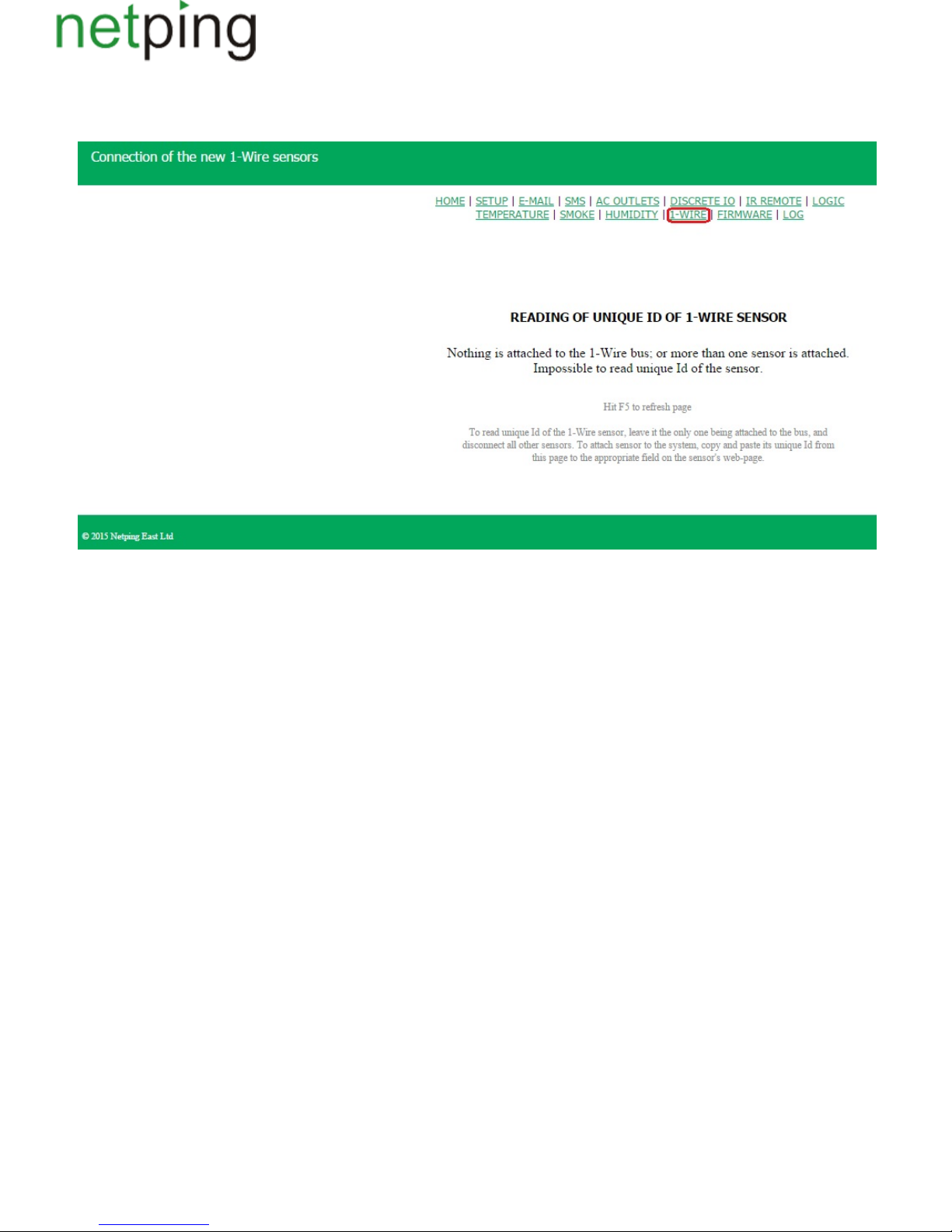
1.
2.
3.
[ENG] 6.2. [DKSF 48.4 IU] How to Determine a Unique Number of a 1-Wire Smoke Sensor?
To read a unique Id of a 1-Wire sensor, there is a need to go to the page « » of a device web interface:1-WIRE
To determine a unique Id using a web interface, there is a need to do as follows:
Unplug all 1-Wiresensors from a device;
Plug a sensor, which unique number you want to know to a device;
Go to the address or go to the page « » of a web interface. A unique Id of a sensor will behttp://<ip_address_of_a_device>/ow_new.cgi 1-WIRE
displayed in the browser window.
A unique number of a 1-Wiresensor looks like the following (16hexadecimal digits:2818 0ea2 0600 0039 0..9,a..f).
To plug a 1-Wire sensor, copy its unique number from this page to a corresponding field at the page of a web interface.
Copyright © NetPing east Co., Ltd E-mail: Phone:+886-2-23121582[email protected]
Page 62
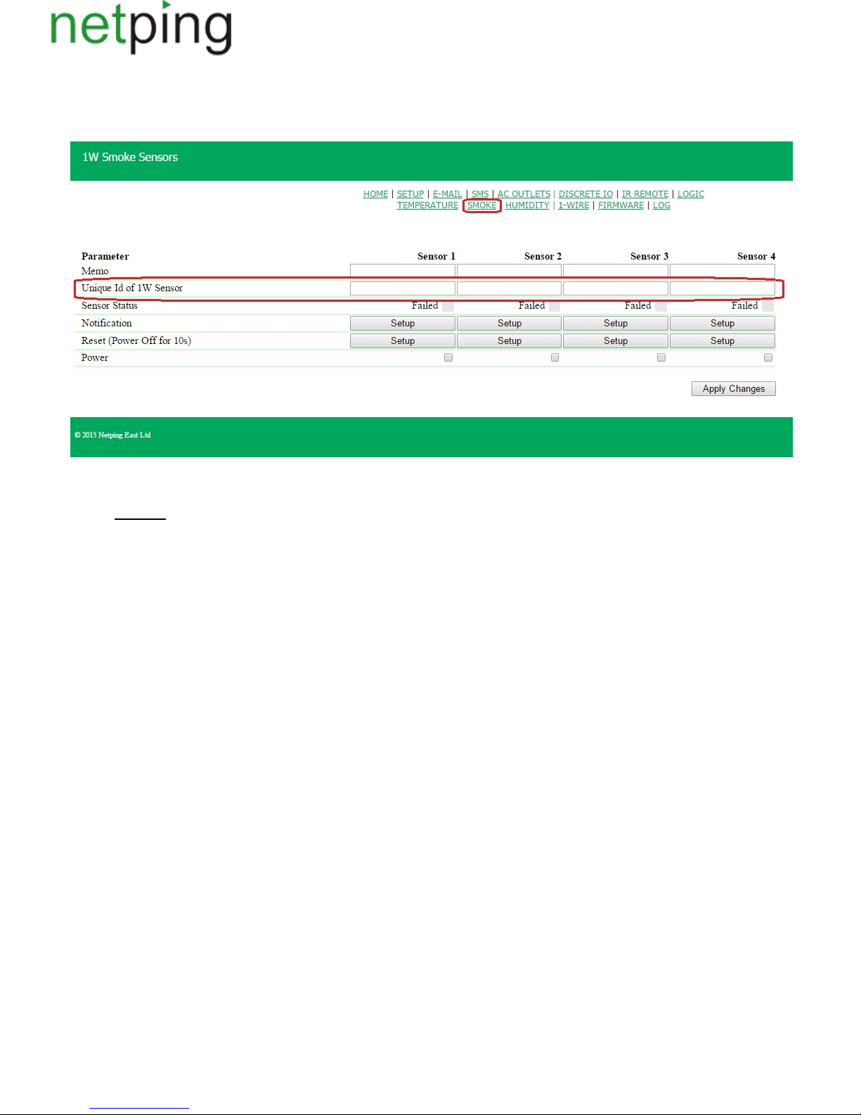
1.
2.
[ENG] 6.3. [DKSF 48.4 IU] Initial Configuring of Smoke Sensors
At the page « » of a device web interface,a status of smoke sensors, connected to a deviceis displayed. It is possible to plug up to four smokeSMOKE
sensors of a 1-Wire model line to a device.
To plug a sensor, indicate its Id in the field « .Unique Id of 1W Sensor»
Unique Id of 1W Sensor– is unique Id of a 1-Wire smoke sensor, which is connected to the 1W socket. The address consists of 4 four-digit hexadecimal
numbers. :On default empty line
You can know a unique Id of a 1-Wire sensor in two ways:
A unique Id of a 1-Wire smoke sensor is indicated on the sticker at the sensor.
You can know a unique Id of a 1-Wire smoke sensor from reading the section «6.2. [DKSF 48.4 IU] How to Determine a Unique Number of a
»1-Wire Smoke Sensor?
Copyright © NetPing east Co., Ltd E-mail: Phone:+886-2-23121582[email protected]
Page 63
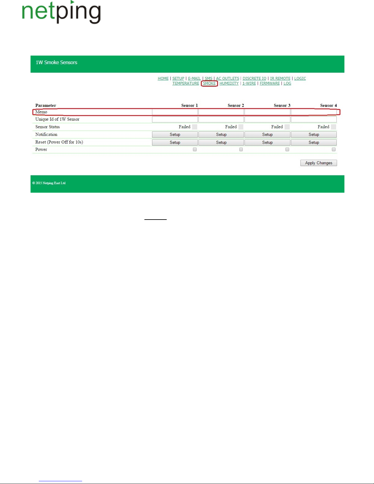
[ENG] 6.4. [DKSF 48.4 IU] Is It Possible to Set Description for Smoke Sensors?
To set a description for smoke sensors, there is a need to go to the page « » of a device web interface:SMOKE
Description of smoke sensors is set at the field « ».Memo
Memo– is a field for setting a brief description of a smoke sensor. A memo is used in SYSLOG and log file notifications, and is included into SNMP
TRAP notifications. Its maximum size is 30 characters.On default: empty line
Copyright © NetPing east Co., Ltd E-mail: Phone:+886-2-23121582[email protected]
Page 64
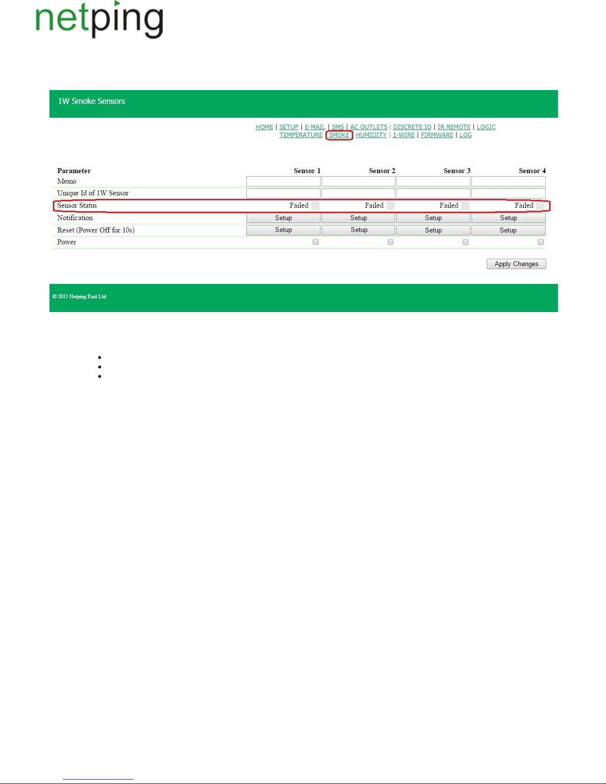
[ENG] 6.5. [DKSF 48.4 IU] How to Browse a Current Status of Smoke Sensors?
To see a current status of smoke sensors, there is a need to go to the page « » of a device web interface:SMOKE
Status – displays a current status of a smoke sensor.
Possible values:
Normal– a smoke sensor is in a normal state;
Alarm – a smoke sensor registered smoke;
Failure– a smoke sensor is not connected or does not respond
Copyright © NetPing east Co., Ltd E-mail: Phone:+886-2-23121582[email protected]
Page 65
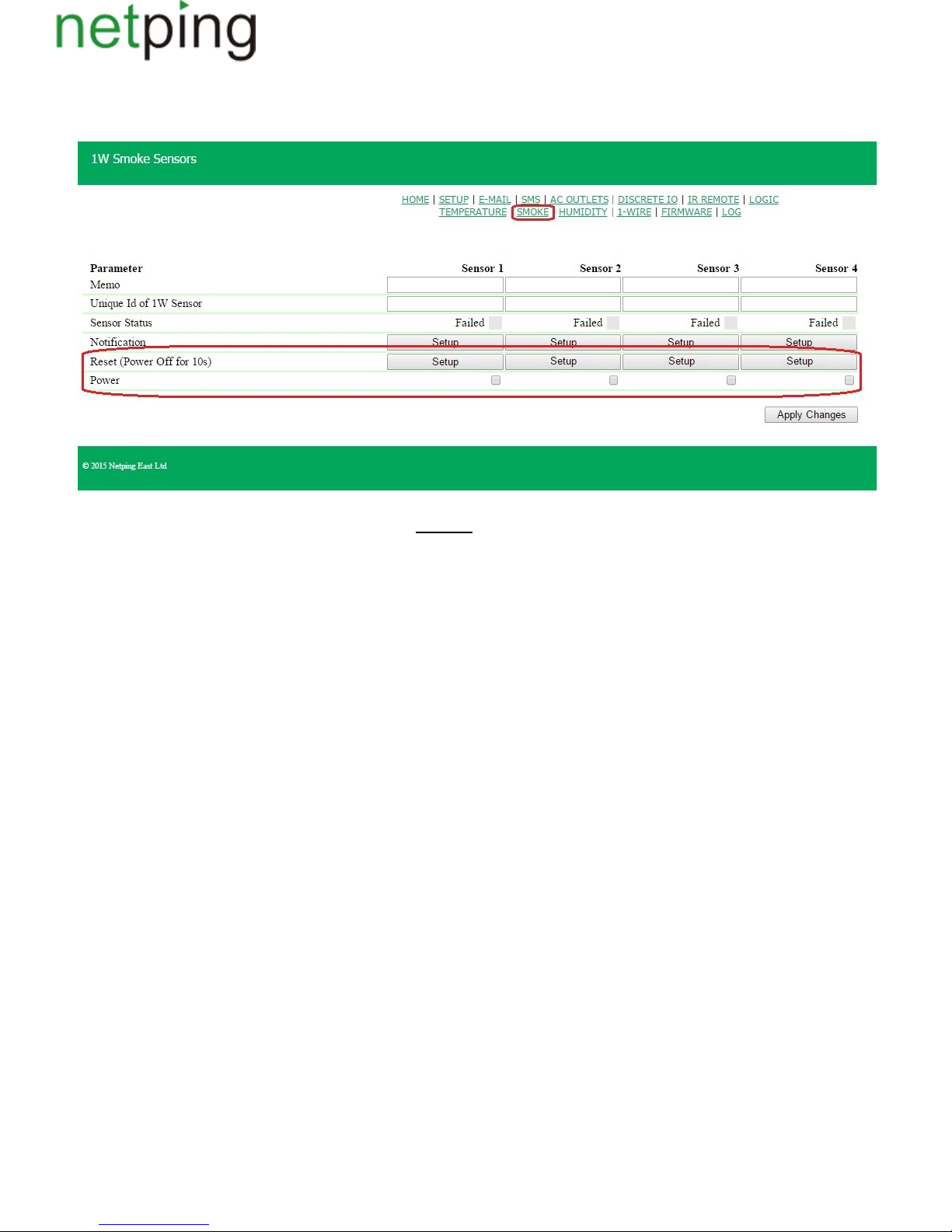
[ENG] 6.6. [DKSF 48.4 IU] How to Turn a Power Off and Reset a Smoke Sensor?
Power supply or reset of smoke sensors is managed at the page « » of a device web interface:SMOKE
A checkbox « » allows to supply voltage to smoke sensors. Power : checkbox is not checkedOn default
A status « » of smoke sensors is reset by clicking the button « ». In this case, there will be no power supply at smoke sensors during 10Alarm Reset
seconds.
Copyright © NetPing east Co., Ltd E-mail: Phone:+886-2-23121582[email protected]
Page 66
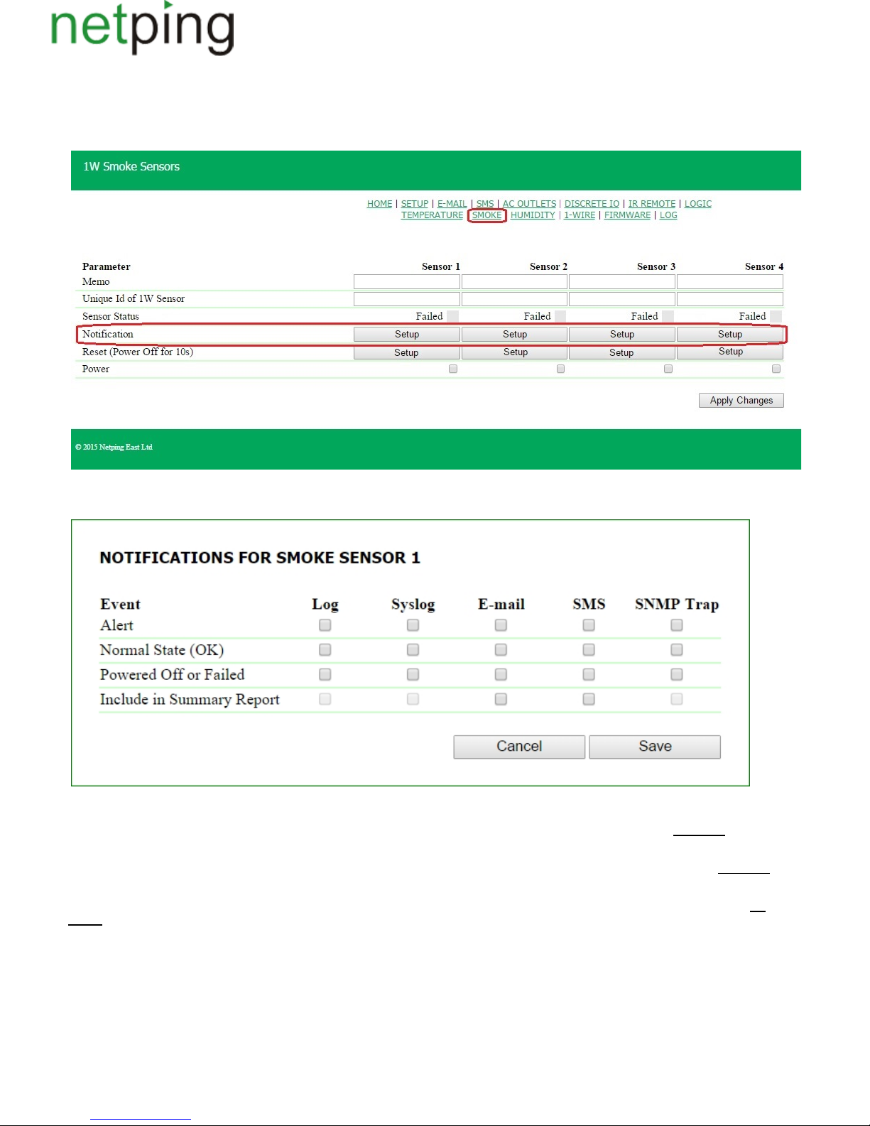
[ENG] 6.7. [DKSF 48.4 IU] I Want to Configure Sending Notifications When a Sensor Status Is Changed. How to
Do This?
Sending notifications when a status of a smoke sensor is changed is configured at the page « »of a device web interface:SMOKE
When clicking the button « » a menu of settings appears for sending notifications of the next types: Log, Syslog, e-mail, SMS (in a device withConfigure
an embedded GSM modem) and SNMP Trap:
where:
Alert – is a checkbox, when checked a device will send notifications if a smoke sensor has been switched into a status «Alert». : checkbox isOn default
not checked
Normal State – is a checkbox, when checked a device will send notifications if a smoke sensor has been switched into a «normal state». :On default
checkbox is not checked
Отказ, Отключение– is a checkbox, if checked a device will send notifications if a connection is lost or when a smoke sensor is de-energized . On
: checkbox is not checkeddefault
After setting all necessary parameters, click the button .«Apply changes»
Copyright © NetPing east Co., Ltd E-mail: Phone:+886-2-23121582[email protected]
Page 67

[ENG] 7. [DKSF 48.4 IU] Working with Discrete Input-Output Channels
Copyright © NetPing east Co., Ltd E-mail: Phone:+886-2-23121582[email protected]
Page 68
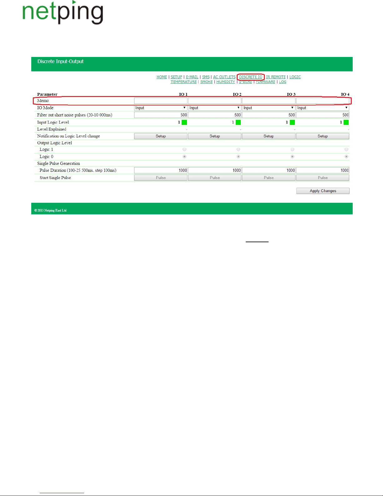
[ENG] 7.1. [DKSF 48.4 IU] Is It Possible to Set a Description for an Input-Output Line?
To set a description for an input-output line, there is a need to go to the page « » of a device web interface:DISCRETE IO
Descriptions for IO lines are set in the field « ».Memo
Memo– is a field for setting a brief description of an IO line. A memo is used in the notifications and is included into SNMP TRAP,SYSLOG and log
SMS, e-mail notifications, e-mail reports about a status of sensors. Its maximum size is 30 characters.On default: empty line
Copyright © NetPing east Co., Ltd E-mail: Phone:+886-2-23121582[email protected]
Page 69
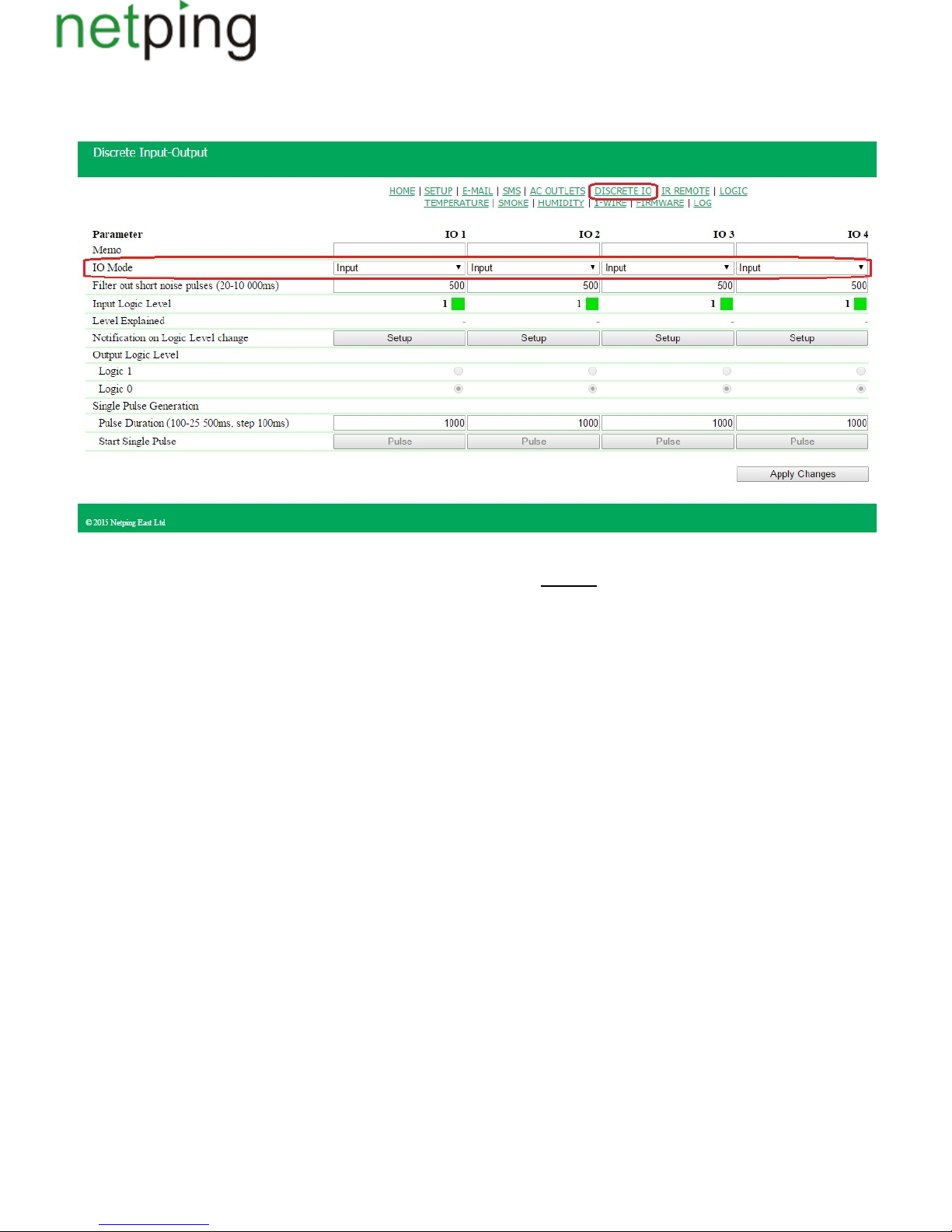
[ENG] 7.2. [DKSF 48.4 IU] Configuring Operation Mode of an Input-Output Line
To set an operation mode of an IO line, there is a need to go to the page « » of a device web interface:DISCRETE IO
where:
IO Mode– allows to set an IO line into the mode « »,« » and« ».input output logic output : inputOn default
At the page « »,current settings of discrete input-output channels are displayed. In the mode « », « » and « »it isDISCRETE IO input output logic output
possible to configure automatic sending of SNMP TRAP, SYSLOG, e-mail, and SMS notifications, notifications into a log file as well as periodic
reports about a status. In the mode « », it is possible to set a logic level at a line through the web, SNMP and HTTP API interfaces. In the mode «output
», a logic level at a line is set by a logic module.logic output
Copyright © NetPing east Co., Ltd E-mail: Phone:+886-2-23121582[email protected]
Page 70
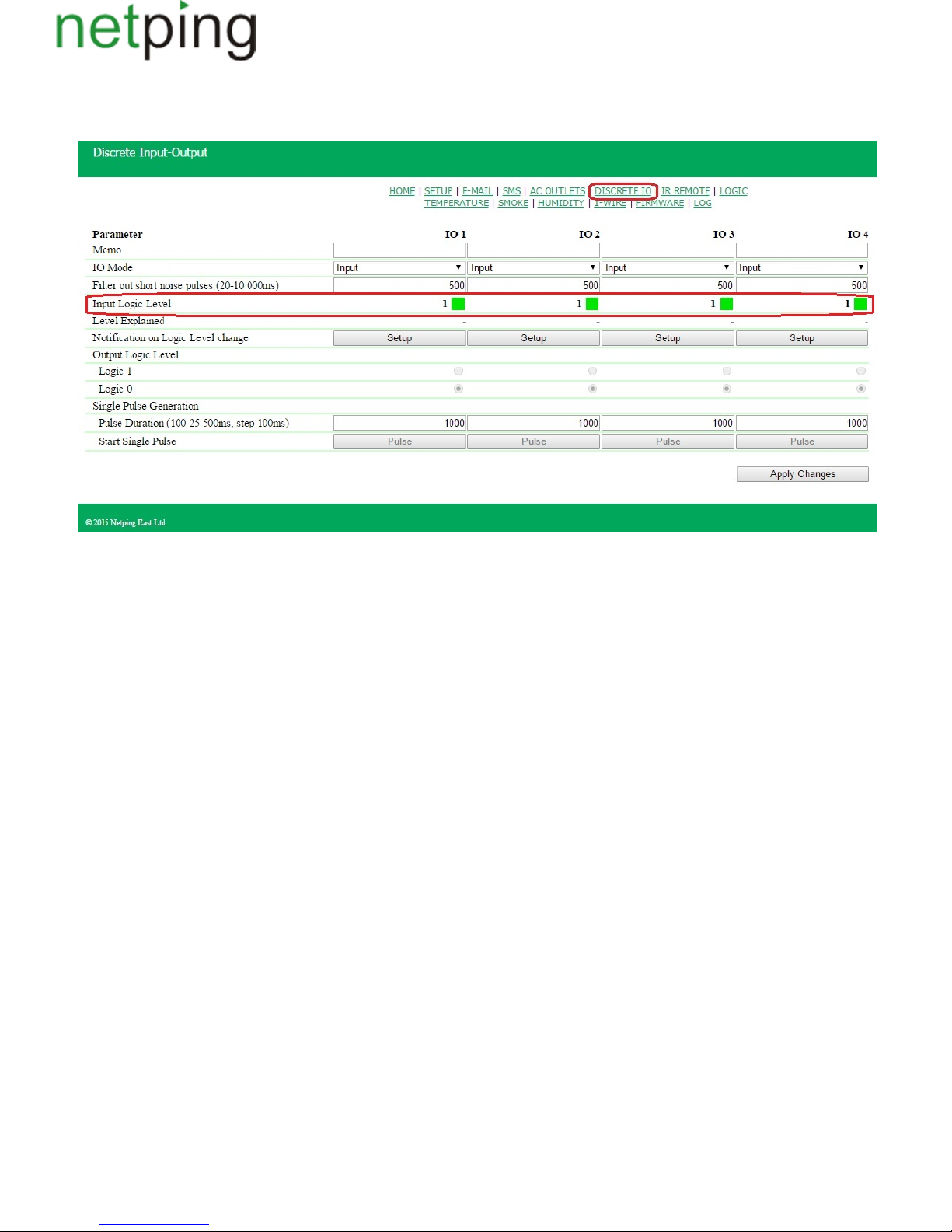
[ENG] 7.3. [DKSF 48.4 IU] How to Define a Current Logic Level at an Input-Output Line?
To define a current logic level of an IO line, there is a need to go to the page « » of a device web interface:DISCRETE IO
where:
Input Logic Level– is a field displaying a current logic level at an IO line. It is updated automatically when a logic level of a line is changed with no need
to reload an entire page.
Copyright © NetPing east Co., Ltd E-mail: Phone:+886-2-23121582[email protected]
Page 71
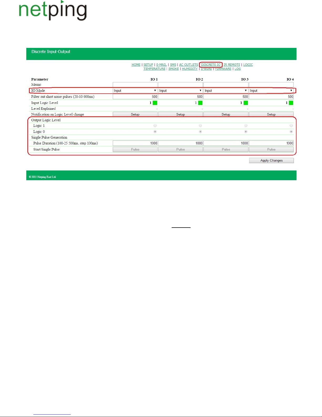
1.
2.
3.
[ENG] 7.4. [DKSF 48.4 IU] How to Manage an Input-Output Line in the Output Mode?
To manage an IO line, there is a need to go to the page « » of a device web interface:DISCRETE IO
Set an IO line to the operation mode;«output»
Check a checkbox « » at « » or « »;Output Logic Level Logic 1 Logic 0
Save parameters by clicking the button « »Apply Changes
Input Logic Level– is a field displaying a current logic level of an IO line. It is updated automatically when changing a logic level of a line with no need
to reload an entire page;
Output Logic Level– is a parameter of a logic level of a line, which works as an « ». A status means having voltage at an output line (aoutput logic «1»
scheme with an open collector). A logic means having 0V at an IO line.status «0» : logic« »;On default 0
Single Pulse Generation–when clicking the button « », anIO line, which works as an output, will be inverted for a specified period of time. A pulsepulse
duration is set in the field « . If a line is set to « »,then the button for issuing a pulse will not be active.Pulse Duration (100-25500ms, step 100ms)» output
Copyright © NetPing east Co., Ltd E-mail: Phone:+886-2-23121582[email protected]
Page 72
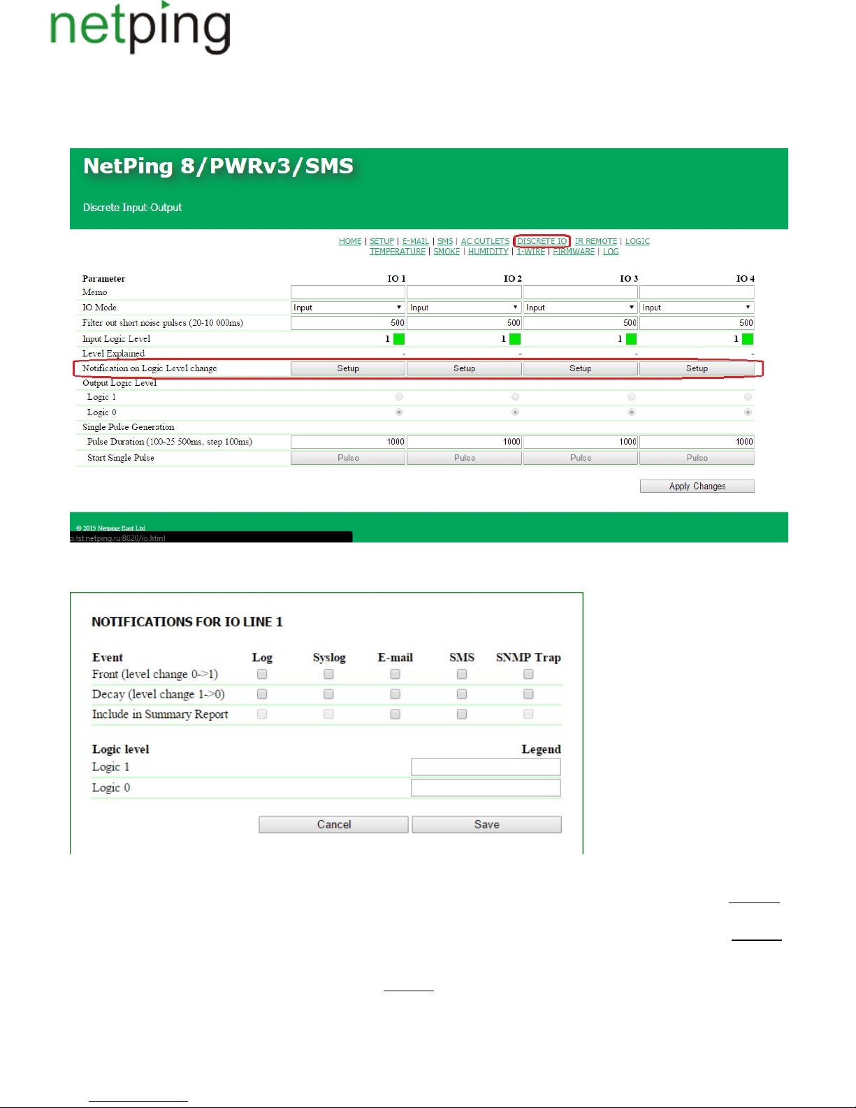
[ENG] 7.5. [DKSF 48.4 IU] I Want to Configure Sending Notifications When Changing a Logic Level of an
Input-Output Line. How to Do This?
Notifications on changing a logic level of an IO line are configured at the page « »of a device web interface:DISCRETE IO
When clicking the button « » a menu of settings appears for configuring sending notifications of the next types: Log, Syslog, E-mail, SMS (inSetup
devices with an embedded GSM modem) and SNMP Trap, as well as encoding numeric values of a current level of an IO line:
where:
Front (level change 0->1)– is a checkbox, when checked a device will send notifications if a status of an IO line is changed from 0 to 1 .« » « » :On default
checkbox is not checked
Decay (level change 1->0)– 1 to 0 .is a checkbox, when checked a device will send notifications if a status of an IO line is changed from « » « » :On default
checkbox is not checked
Include in Summary Report –is a checkbox, when checked a device will send reports about a status of an IO line via e-mail and/or SMS. Time for
sending reports is configured at the pages «SMS» and «E-MAIL». : checkbox is not checkedOn default
Logic level Logic 1 a clear and understandable of a numeric value of a level of an IO line . This decoding will be displayed– description «Logic 1» is set
in the field « »at the page« » of a device web interface and will be added to SNMP TRAP notifications.Legend INPUT-OUTPUT
Copyright © NetPing east Co., Ltd E-mail: Phone:+886-2-23121582[email protected]
Page 73

0Logic level Logic – .a clear and understandable description of a numeric value of a level «Logic 0» of an IO line is set This decoding will be displayed
in the field «Legend»at the page«INPUT-OUTPUT» of a device web interface and will be added to SNMP TRAP notifications.
After setting all necessary parameters click the button .«Apply changes»
Copyright © NetPing east Co., Ltd E-mail: Phone:+886-2-23121582[email protected]
Page 74
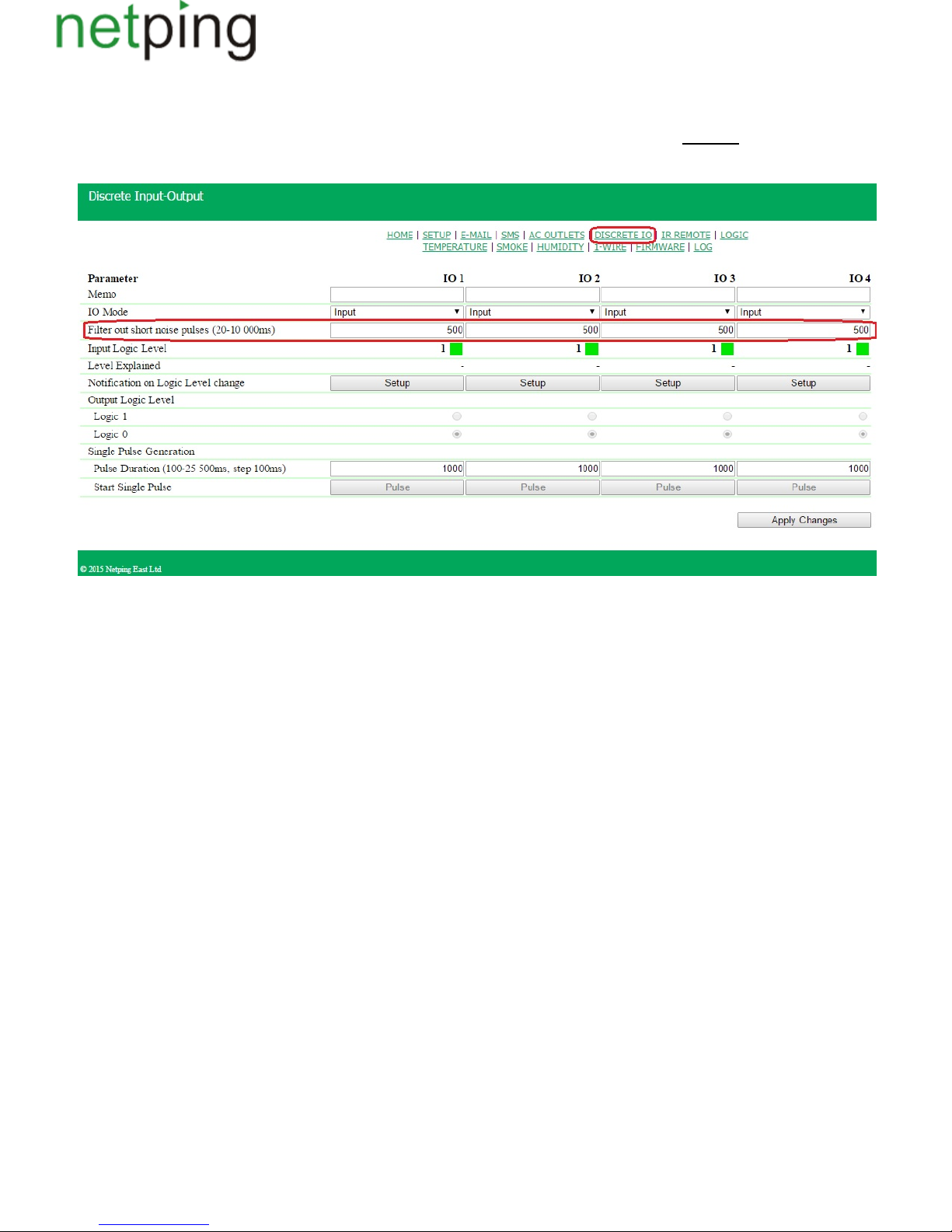
[ENG] 7.6. [DKSF 48.4 IU] For What a Filter for Short Noises Is Necessary in Settings of an Input-Output Line?
Filter out short noise pulses(20-10 000 ms) - is a field for setting a period of time, during which an IO line configured as an « », must stay stable toinput
register its status. Hence, this parameter allows to filter out short noise signals or bouncing of mechanical contacts. : 500msOn default
A filter for short noise pulses is configured at the page « »of a device web interface:DISCRETE IO
Copyright © NetPing east Co., Ltd E-mail: Phone:+886-2-23121582[email protected]
Page 75

[ENG] 8. [DKSF 48.4 IU] Working with Built-In Relays
Copyright © NetPing east Co., Ltd E-mail: Phone:+886-2-23121582[email protected]
Page 76
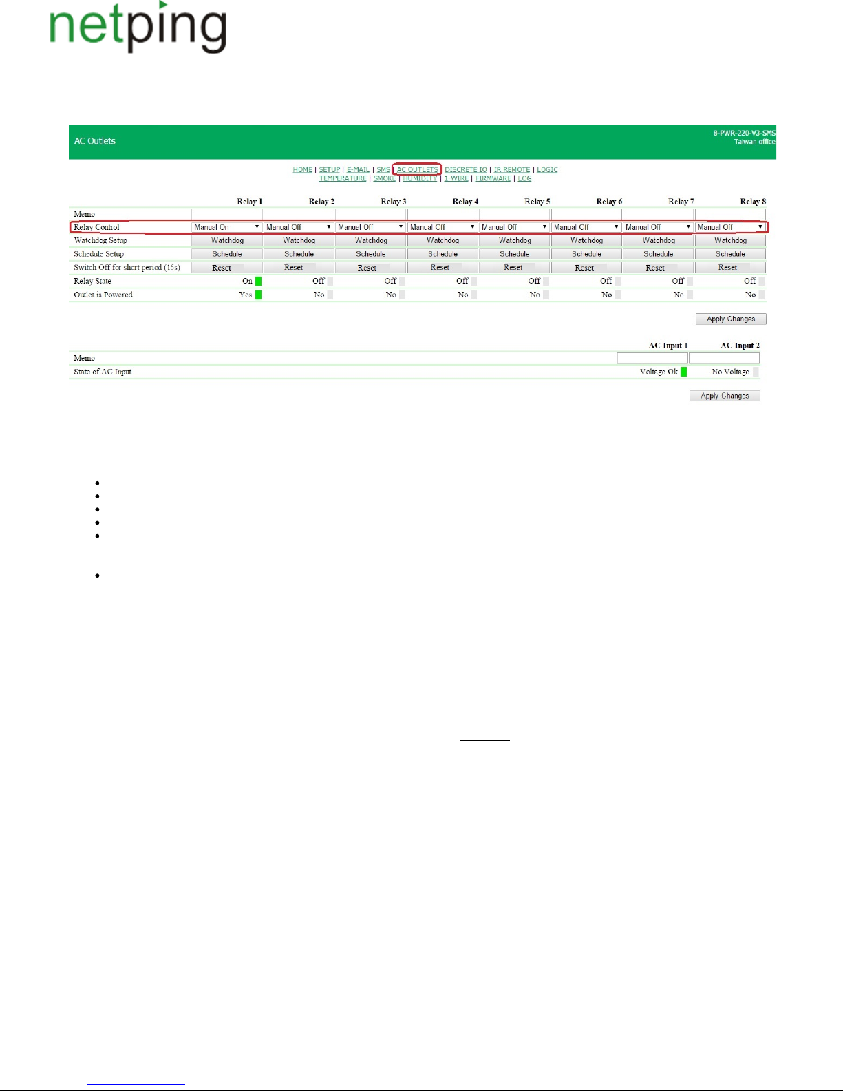
[ENG] 8.1 [DKSF 48.4 IU] Configuring Relay Management Modes
Management modes of built-in relays are configured at the page « » of a device web interface:AC OUTLETS
This page allows to control eight output channels (relays) of a device power supply. A channel may be switched off for a short time, set to the mode «M
»,« »,« », « », « », « ».anual Off Manual On Schedule Watchdog Schedule+Watchdog Logic Output
Relay Control– is a current status of a relay. It is possible to specify the next values:
Manual Off– a relay is constantly switched off;
Manual On – a relay is constantly switched on;
Watchdog – a relay is controlled by the module « »;Watchdog
Schedule – a relay is controlled by the module « »;Schedule
Schedule+Watchdog– a relay is controlled by both modules « » and « » simultaneously. The module « » switches aWatchdog Schedule Schedule
relay on and off. The module « » checks the operability of a connected device depending on the module « ». If the module «Watchdog Schedule
» notices a failure in a device operation (no response to ICMP request), a relay changes its status to the opposite one for a short time;Watchdog
Logic– a relay is used as a logic output
Switch Off for Short Period (15s)– when clicking the button « », a corresponding relay will be switched off for 15 seconds.Reset
Relay State– is a current status of a relay of each of eight sockets. Possible variants are:« »,« ».Off On
Outlet is Powered– is an availability of the voltage for every socket out of eight ones. Possible variants:« »,« ».Yes No
A status of a relay and voltage at sockets are updated automatically when a relay status is changed or a voltage is present with no need to reload the
entire page.
Memo– is a field for viewing or changing a brief description of a relay.A value in this field will be used in SYSLOG notifications, records at the page «
», as well as included into SMS, E-mail notifications, E-mail reports about a status of sensors and indicated in headings of pop-up dialogs andLOG
module configuration «Watchdog» and «Schedule». Maximum size is 30 characters. : emptyline.On default
After setting up all necessary parameters click the button « ».Apply changes
Copyright © NetPing east Co., Ltd E-mail: Phone:+886-2-23121582[email protected]
Page 77

[ENG] 8.2 [DKSF 48.4 IU] I Want to Configure Sending Notifications on Events of Relay Triggering. How to Do
This?
In the firmware version DKSF 48.4.X, only the next types of notifications are enabled on default: log and Syslog. It is also possible to enable SMS
notifications, which are configured at the page « » of a device web interface. Other types of notifications (SNMP Trap and e-mail) are notSMS
implemented for a relay.
Copyright © NetPing east Co., Ltd E-mail: Phone:+886-2-23121582[email protected]
Page 78
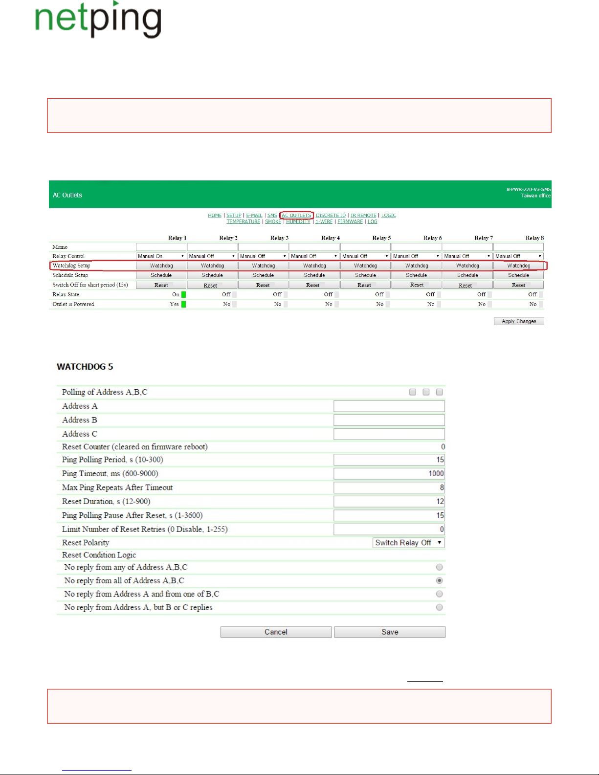
[ENG] 8.3. [DKSF 48.4 IU] What Is «Watchdog», and How to Configure It?
« » is a specific operation mode of a power supply channel, within which specific addresses are constantly requested using ping (ICMP Echo)Watchdog –
in a specified period of time. If there is no response, a device, which is connected to a power supply socket, is reloaded.
To use the module « », there is a need to switch a relay management to the module « » or « at the page «Watchdog Watchdog Schedule+Watchdog» AC
» of a device web interface. To configure the module « », there is a need to click the button «Watchdog», located on any of eightOUTLETS Watchdog rel
ay managementchannels:
All parameters of the module are configured in the next pop-up dialog:
where:
Polling of AddressA,B,C– is a set of checkboxes, which allow to specify addresses for polling individually. : checkboxes are not checkedOn default
If specified IP addresses are out of the IP subnetwork of the device, there is a need to indicate a gateway address to the external network at
the page « » of a device web interface.SETUP
If none checkbox is checked, or IP addresses for checked checkboxes are not specified, polling will not be executed and in fact, the mode «Wa
» will be disabled.tchdog
Copyright © NetPing east Co., Ltd E-mail: Phone:+886-2-23121582[email protected]
Page 79
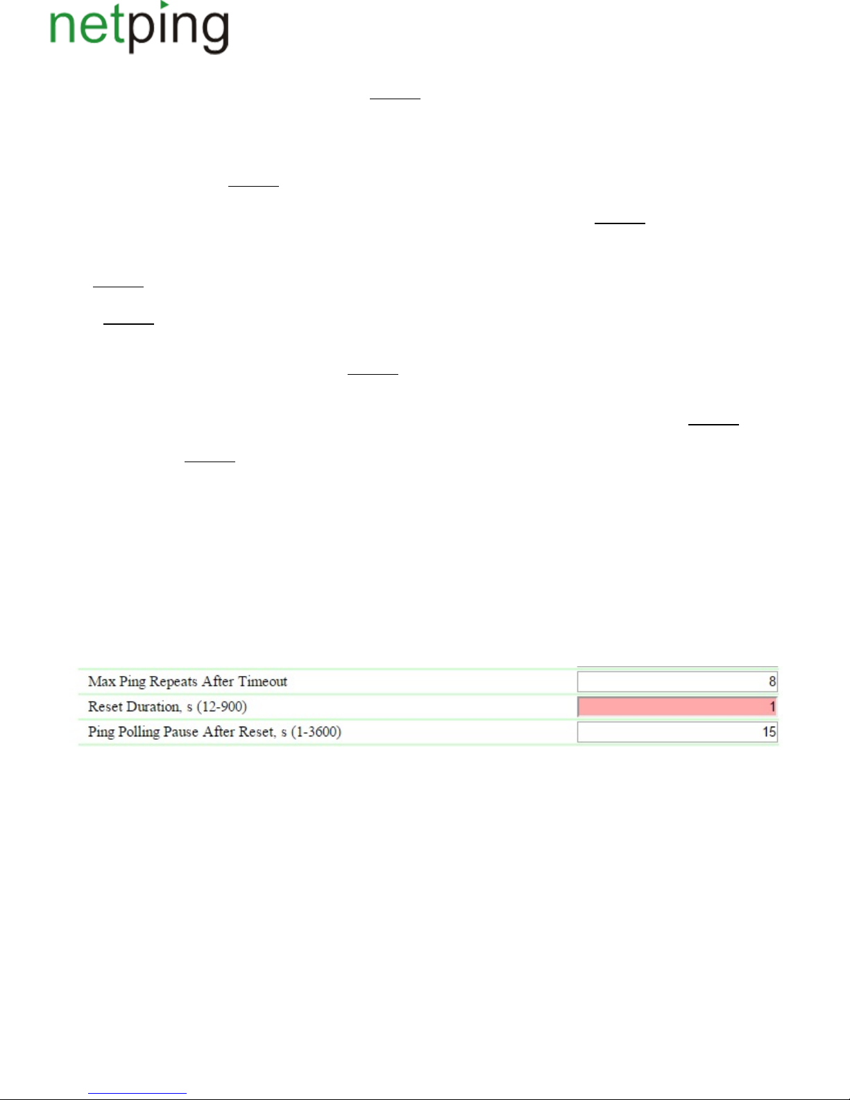
Address A( ) – is a field for viewing or changing addresses for polling. It is acceptable to indicate an IP address or a domain name. It is possible toB,C
configure up to three addresses. An empty field disables polling. : address is not setOn default
Reset Counter (cleared on firmware reboot)– is an informational field, which shows how many times a channel has been reloaded as a result of «Watch
» operation. A counter does not count an amount of resets in the «manual mode». A counter is reset when a NetPing device is unplugged from adog
power supply.
Ping Polling Period, s (10-300)– is a field for setting a period of time, within which repeated ICMP Echo (ping) are sent to indicated IP addresses after
responses from them are received. : 15 sOn default
Ping Timeout, ms (600-9000)– is a field for setting a timeout before repeating ICMP Echo (ping). A value must exceed a usual response time for ICMP
Echo (ping) for a given network including certain reserve to exclude false triggering of the module « ». Watchdog : 1000 msOn default
Max Ping Repeats After Timeout- is a field for setting up a maximum number of attempts to receive a response to ICMP Echo (ping). If the number of
attempts is over, IP address is considered «silent». It is desirable for a period of pollingrepeating to exceed a timeout ICMP Echo (ping) multiplied by a
maximum number of attempts. If this condition is not fulfilled, then a new request cycle will be postponed until an indicated amount of attempts is
over. : 8On default
Reset Duration, s (12-900)– is a field for setting time, for which a device that is plugged into a power supply sockets is de-energized to initiate reset and
reboot. : 12 sOn default
Ping Polling Pause After Reset, s (1-3600)– is a field for setting time, for which polling is paused after switching on a power supply socket. A pause is
necessary for a device to have enough time to reboot, initialize and restore the functioning of its network interfaces. Otherwise, it is possible to get an
endless repeating of triggering of the module « ». Watchdog : 15 sOn default
Limit Number of Reset Retries (0 disable, 1-255)– is a field for setting the amount of consequent resets, after which the module « » for thisWatchdog
channel will be switched to a standby mode. At the same time, polling is continued, but a connected device is not reset. A standby mode ends when a
response to ICMP Echo (ping) is received. The value «0» of this parameter disables a limitation for an amount of consequent resets. : 0On default
Reset Polarity– is a field which allows to indicate what will be executed to reset a connected load to an output power supply channel: «Switch Relay Off
» or « ».Switch Relay On : Switch Relay OffOn default
Reset Condition Logic– determines a condition, within which a reset of a device connected to a power supply channel will be performed.
No Reply from Any of Address (A,B,C)– a connected device will be reloaded, if at least one address did not respond.
No Reply from All of Address (A,B,C)– a connected device will be reset only if all addresses indicated for polling did not respond.
No Reply from AddressA and from one of В or С– a connected device will be reset if address А did not respond as well as any of addresses В or С, or
both B and C.
No Reply from Address А, but B or C – a connected device will be reset only if address A did not respond, but address B or address C didreplies
respond. This means if all addresses do not respond, a connected device will not be reloaded.
After setting all necessary parameters click the button « », for a device to execute a command.Apply changes
If any parameter will be set incorrectly, it will be highlighted in red:
There is a need to correct a value of a parameter and click the button « » once again.Apply changes
Copyright © NetPing east Co., Ltd E-mail: Phone:+886-2-23121582[email protected]
Page 80
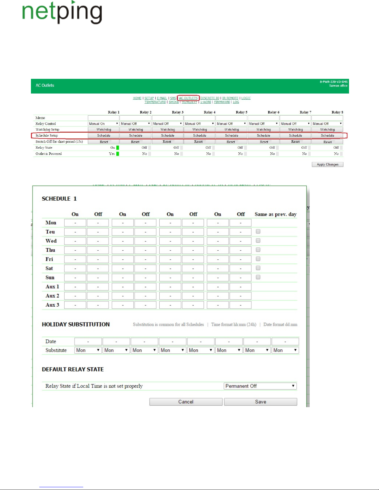
[ENG] 8.4. [DKSF 48.4 IU] What Is «Schedule», and How to Configure It?
The module « » allows to set a schedule, according to which a relay will be switched on and off.Schedule
To use the module « », a relay management needs to be set to the mode « » or « at the page « » ofSchedule Schedule Schedule+Watchdog» AC OUTLETS
a device web interface. To configure the module « », there is a need to click the button «Schedule», located at any of eight built-in relaySchedule
management channels:
All parameters of the module are configured in the next pop-up dialog:
Weekly Schedule
A schedule for a relay management is set at the settings dialog. For each day of the week, it is possible to configure four intervals during which a relay
will be switched on.
An interval starts from the time of switching a relay on (column « ) and ends with the time of switching off (column « »). Time is specified in theOn» Off
Copyright © NetPing east Co., Ltd E-mail: Phone:+886-2-23121582[email protected]
Page 81
next format « » in the range – . Time must increase from left to right: in the interval the time of switching on must take place beforehh:mm 00:00 23:59
the time of switching off, the time of switching on in the interval 2 must be after the time of switching off in the interval 1. The cells can be left blank,
and in this case, the next filled cell will work. For example, it is acceptable to switch on « » and switch off on « ».Mon Fri
The column « » allows to apply a schedule of a previous day to the next day in one click, thus making schedule configuration easier. ToSame as prev.day
apply a schedule of the previous day to the current one, check a corresponding checkbox.
Time of the action (« or « ), which has been performed the last, is displayed at the page in bold, which allows to quickly determine which actionOn» Off»
and in what interval will be performed the next.
Holiday Substitution
Lines « », « », « » allow to set a special schedule for holidays. This schedules can be linked to holidays in the section « ».H 1 H 2 H 3 Holiday Substitution
The section « » allows to set a special schedule for holidays or link a schedule of any workday to the holiday. Up to eight holidaysHoliday Substitution
can be saved in the memory of the device.
In the line « », a date of a holiday is indicated in the format « » in the range – .Date dd.mm 01.01 31.12
In the line « » a schedule is indicated, which will be used in this day. A drop-down list allows to choose the next variants: « », « », «Substitute Mon Tue We
», « », « », « », « », « », « », « ».d Thu Fri Sat Sun H1 H2 H 3
A Default Relay Status
When the clock have failed to be installed, a relay status determines a reaction of the relay in the moment of the clock reset in a built-in clock of a
device. The next modes are possible:« », « », « ».Permanent On Permanent Off Ignore Failure
Permanent On –when a local time is not properly set, a relay will be permanently on regardless a specified description.
Permanent Off– when a local time is not properly set, a relay will be permanently off regardless a specified description.
Ignore Failure– when a local time is not properly set, a relay will continue operating on the basis of a configured schedule.
After setting up all necessary parameters, click the button « ».Apply changes
This setting is activated when a time is reset to the date before 2000 year. If time is reset to the date after 2000 year, then a device will not use
this setting.
Copyright © NetPing east Co., Ltd E-mail: Phone:+886-2-23121582[email protected]
Page 82

[ENG] 9. [DKSF 48.4 IU] Working with Device Power Supply Inputs
Copyright © NetPing east Co., Ltd E-mail: Phone:+886-2-23121582[email protected]
Page 83
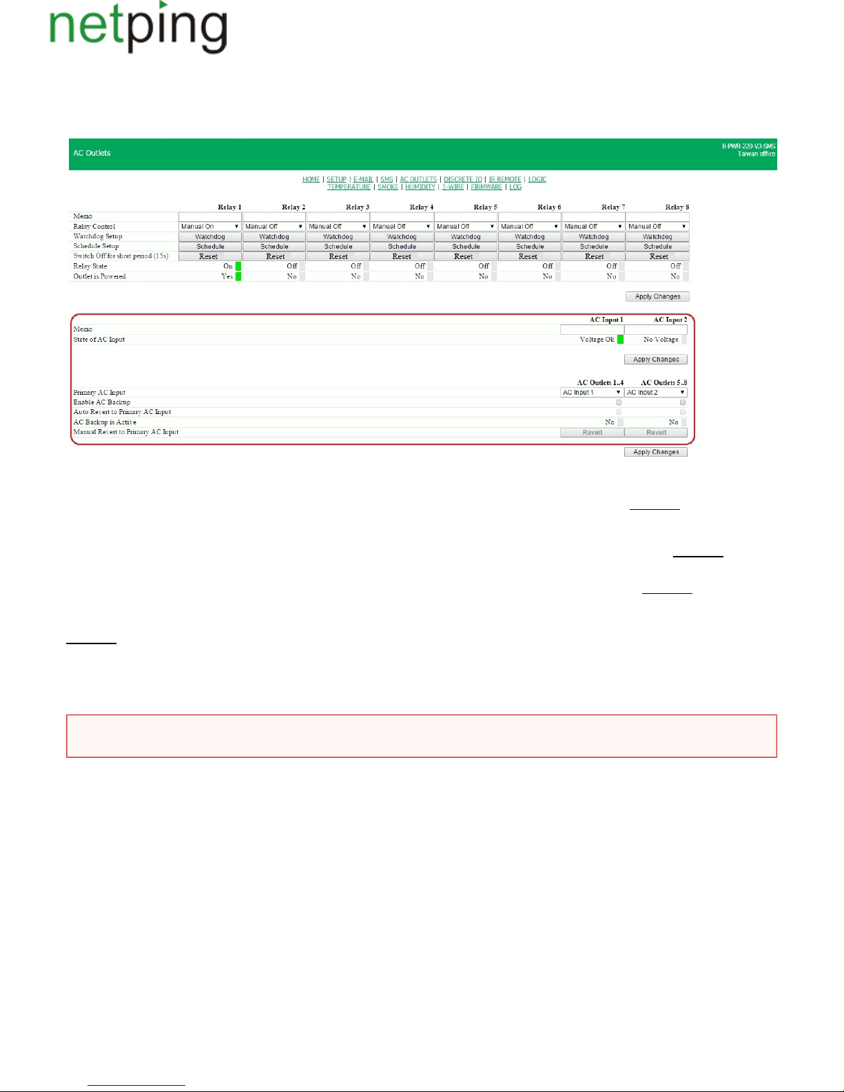
[ENG] 9.1. [DKSF 48.4 IU] Configuring Power Supply Inputs in a Device Web Interface
Power supply inputs of a device are configured at the page « » of a device web interface. Here it is possible to indicate an input, fromAC OUTLETS
which groups of power supply channels will be fed and install additional parameters of the automation of power supply inputs:
In the configuration area of power supply inputs, it is possible to configure the next parameters:
Memo– is a field for viewing or changing a brief description of a power supply input. Its maximum size is 30 characters. ;:empty lineOn default
State of AC Input– displays a voltage availability at inputs of a device. Possible statuses are:« », « »;No voltage Voltage available
Primary AC Input – is a setting of the main input for each group sockets. Both groups of sockets can be fed from the same input. : inputOn default 1 is
;a main one for the sockets 1..4, input 2 is a main one for the sockets 5..8
Enable AC Backup – is a checkbox, which enables switching one group of sockets to a backup input if the main input fails. : a checkbox isOn default
;not checked, switching to the backup input is not performed
Auto Revert to Primary AC Input – is a checkbox, when checked a group of sockets will forcedly switch to the main input after a voltage appears on it.
;: a checkbox is not checkedOn default , auto revert to the main input is not performed
AC Backup is Active – displays a state of the function for backing up an input for each group of sockets. Possible statuses:« », « »;On Off
Manual Revert to Primary AC Input – is a button, clicking which a group of sockets will switch from a backup input to themain one. The button is
active when the mode «Switch to a backup input» is enabled for a group of sockets. This is an alternative for a function «Autorevert to the main input».
After the parameters were changed, there is a need to click the button « ».Apply changes
Switching of groups of sockets between power supply inputs is accompanied with switching off sockets for a short time!
Copyright © NetPing east Co., Ltd E-mail: Phone:+886-2-23121582[email protected]
Page 84

[ENG] 10. [DKSF 48.4 IU] Working with the Module «Logic»
Copyright © NetPing east Co., Ltd E-mail: Phone:+886-2-23121582[email protected]
Page 85
[ENG] 10.1. [DKSF 48.4 IU] What Is «Logic»?
A logic module of a firmware is designed for a simple automation and can perform such tasks as maintaining a microclimate, controlling automatic
turning on - turning off a backup equipment, etc. The logic operates on the basis of rules programmed by a user through a web interface.The page «LO
» of a device web interface describes an operating algorithm of a module and its configuration capabilities.GIC
It is prohibited to use a NetPing device to manage electrical circuits when a violation of the control may cause a significant damage.
Copyright © NetPing east Co., Ltd E-mail: Phone:+886-2-23121582[email protected]
Page 86
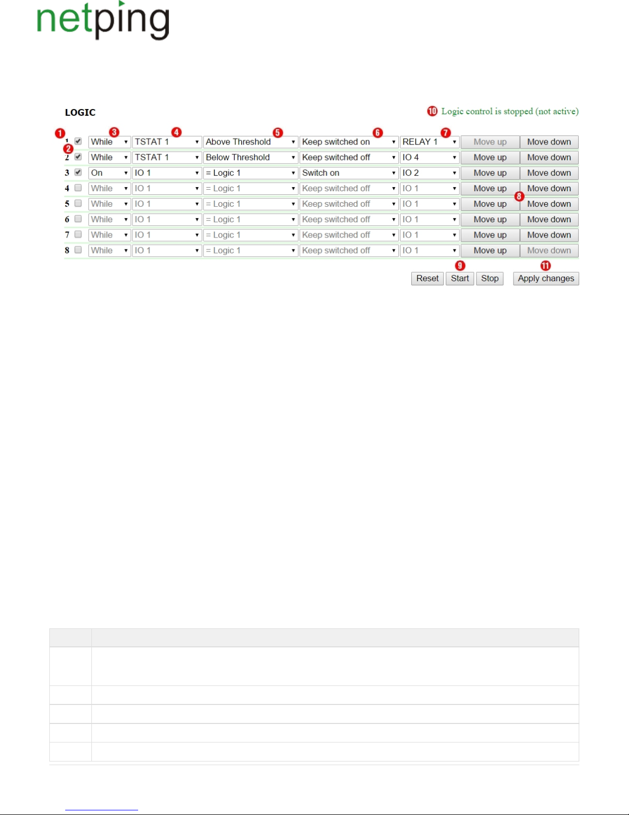
[ENG] 10.2. [DKSF 48.4 IU] How to Use the Module «Logic»?
Rules allow to set a flexible logic scheme for controlling IO lines, relays, IR extension module, smoke sensors and sending SNMP SET commands
depending on altering external conditions.
1.Rule Number
The less is a number of a line, the higher is a rule's priority. If two rules form a conflicting outgoing command (switch on and switch off an output
simultaneously), a rule with a higher priority will work. If rules do not conflict, and control different outputs or form non-conflicting commands then a
correlation of their priorities does not influence their operation.
Rules of « » type always have a higher priority in relation to rules of « » type, regardless their mutual location in the list.While If
A priority of a rule (its position in the list) can be changed by using buttons « » (« » and « ») at the end of the line.8 Move up Move down
2. Checkbox for Enabling a Rule
A rule can be enabled by checking a checkbox. Inactive rules are displayed in gray.
3. Rule Type (Rule Operation Mode)
Possible values are: «While», «If». «While» rules respond to a status of an input and operate constantly. «If» rules respond to changes in a status of an
input (the second position in the rule line).
«While» rule is designed to program conditions, within which an output is constantly kept in a specified status while a condition is fulfilled. When a
condition is not fulfilled, an output status can be changed by other rules.
An «If» rule is designed to program a momentary reaction to a specified event, such as changing of a logic level at an IO line or losing a response when
Pinger works. When an input of a rule remains unchanged, an «If» rule does not influence a status of its output, even if a condition of a rule is fulfilled.
« » rules always have a , than « » rules.While higher priority If
For example, when one of «While» rules keeps an output switched off, rules of «If» type, which switch on an output on a specified event, will not work.
4. Input
An input is a source of information for a rule operation. Its possible values are represented in the table:
Marking Explanation
RESET It is a signal, which is active 5 seconds after a module « »has started or a module « »has been reset using the button « »atLogic Logic Reset
the web page. It is used for a hardware initialization. For example, it is possible to program a 5-second pulse at a relay when a logic is
started or issue an IR command for switching a device off
IO 1 IO line 1. I efore usingt must be set to the mode «input»at the page «INPUT-OUTPUT» b
IO 2 IO line 2. It must be set to the mode «input»at the page «INPUT-OUTPUT» before using
IO 3 IO line 3. It must be set to the mode «input»at the page «INPUT-OUTPUT» before using
IO 4 IO line 4. It must be set to the mode «input»at the page «INPUT-OUTPUT» before using
Copyright © NetPing east Co., Ltd E-mail: Phone:+886-2-23121582[email protected]
Page 87
TSTAT1Thermostat 1. A thermostat must be configured at the page «LOGIC» before using
TSTAT2Thermostat 2. A thermostat must be configured at the page «LOGIC» before using
PINGER1Pinger 1. A pinger must be configured at the page «LOGIC» before using
PINGER2Pinger 2. A pinger must be configured at the page «LOGIC» before using
SMOKE1Smoke sensor at the channel 1. It must be configured at the page before using«SMOKE»
SMOKE
2
2. Smoke sensor at the channel It must be configured at the page «SMOKE» before using
SMOKE
3
3. Smoke sensor at the channel It must be configured at the page «SMOKE» before using
SMOKE
4
4. Smoke sensor at the channel It must be configured at the page «SMOKE» before using
5. Condition
A condition, within which a rule is used and a command is issued, which changes an output status. An available set of conditions is changed depending
on a selected type of the task. Conditions represent a sense of an input status.
For a signal «RESET», possible values are « logic 1», «logic 0».
For an IO line possible values are « », « ».logic 1 logic 0
For a thermostat, possible values are « », « ».Below Specified Т Above Specified Т
For a pinger, possible values are «Silent», «Responds».
For a smoke sensor, possible values are « », « », Normal Alarm «Off», «Failure».
An « » rule works only in the moment of fulfilling a condition. A « » rule works all the time when a condition is fulfilled.If While
6. Command
A command, which is performed when a rule works (a condition is fulfilled).
For an « » rule, possible values are « », « », . These commands work in the moment of fulfilling a condition.If Off On «Switch»
For a « » rule, possible values are « », « ». These commands work all the time while a condition is fulfilled.While Keep Off Keep On
7.Output
It is an output, which is controlled by a rule. Its possible values are represented in the next table:
Marking Explanation
IO 1 IO line 1. It must be set to the mode before using«logic output» at the page «INPUT-OUTPUT»
IO 2 IO 2. line It must be set to the mode «logic output» at the page « » INPUT-OUTPUT before using
IO 3 IO 3. line It must be set to the mode «logic output» at the page « » INPUT-OUTPUT before using
IO 4 IO 4. line It must be set to the mode «logic output» at the page « » INPUT-OUTPUT before using
RELAY 1 Relay on the channel 1, built into a body of a device. A relay control must be set to the mode « »at the page «Logic Output AC
» before usingOUTLETS
RELAY 2 2, . Relay on the channel built into a body of a device A relay control must be set to the mode «Logic Output»at the page «AC
OUTLETS» before using
RELAY 3 3, . Relay on the channel built into a body of a device A relay control must be set to the mode «Logic Output»at the page «AC
OUTLETS» before using
Copyright © NetPing east Co., Ltd E-mail: Phone:+886-2-23121582[email protected]
Page 88
RELAY 4 4, . Relay on the channel built into a body of a device A relay control must be set to the mode «Logic Output»at the page «AC
OUTLETS» before using
RELAY 5 5, . Relay on the channel built into a body of a device A relay control must be set to the mode «Logic Output»at the page «AC
OUTLETS» before using
RELAY 6 6, . Relay on the channel built into a body of a device A relay control must be set to the mode «Logic Output»at the page «AC
OUTLETS» before using
RELAY 7 7, . Relay on the channel built into a body of a device A relay control must be set to the mode «Logic Output»at the page «AC
OUTLETS» before using
RELAY 8 8, . Relay on the channel built into a body of a device A relay control must be set to the mode «Logic Output»at the page «AC
OUTLETS» before using
SNMP 1 SNMP Setter 1. It must be configured at the page « » before usingLOGIC
SNMP 2 SNMP Setter 1. It must be configured at the page «LOGIC» before using
IR 1 IR command 1. A command must be recorded and saved into the cell 1 at the page « » before usingIR COMMANDS
IR 2 IR command 2. A command must be recorded and saved into the cell 2 at the page «IR COMMANDS» before using
IR 3 IR command 3. A command must be recorded and saved into the cell 3 at the page «IR COMMANDS» before using
IR 4 IR command 4. A command must be recorded and saved into the cell 4 at the page «IR COMMANDS» before using
SMOKE
RST
Reset of all connected smoke sensors is activated.
8. Buttons Move Up/Move Down
The buttons are designed for changing a position of a rule in the list, thus changing a priority of a rule. If rules form conflicting commands for an
output, then a rule which is higher in the list will work. However, « » rules always have a higher priority in relation to « » rules, regardless theirWhile If
mutual location in the list.
9. Controls
Controls work directly when clicking them. There is no need to click the button « » additionally.Apply changes
The buttons « » and « » control starting and stopping of rules operation. This status is saved when a device is switched off. If rules are stopped,Start Stop
a warning line of a logic status « » appears.10
The button « » sets the outputs controlled by a logic module to the specified initial status « » (off), and initiates a reset signal. Rules, which have a Reset 0
» signal as an input, may switch outputs to the other required initial status. There is a need to take into account that if rules are not stopped«RESET
before clicking the button « », a status of outputs can be changed immediately and a reset command will not have any external effect.Reset
10. Status Line
If rules operation is stopped, then a warning line will appear.
11. Button for Saving Changes
After setting all necessary parameters, click the button «Apply changes».
Copyright © NetPing east Co., Ltd E-mail: Phone:+886-2-23121582[email protected]
Page 89
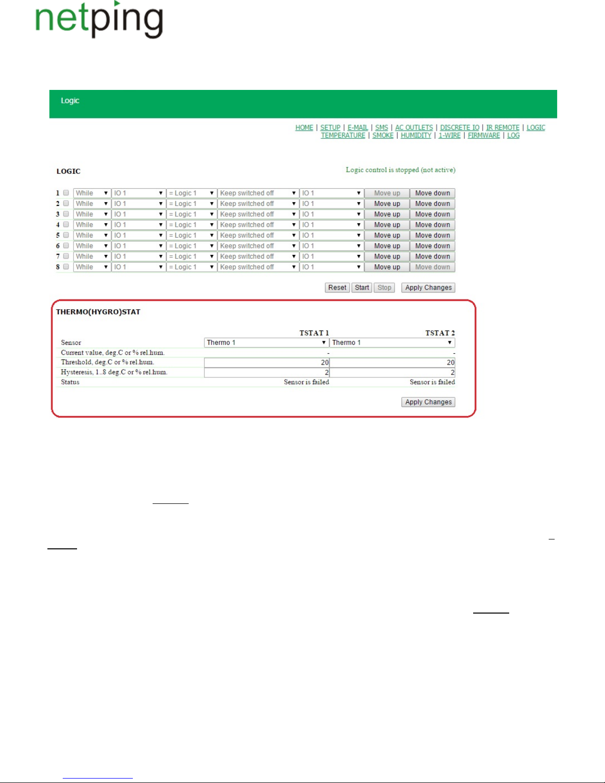
[ENG] 10.3. [DKSF 48.4 IU] Configuring Thermostat
To configure a thermostat, there is a need to go to the page « » of a device web interface:LOGIC
In the section « » parameters of a thermostat are configured.Thermo(Hygro)stat
A thermostat is used to support a constant temperature. Besides a programmed thermostat, there is a need to set a minimum of two rules: one rule for
switching a heater or a cooler on and another one for switching it off. It is possible to configure no more than two channels of a thermostat – «TSTAT 1
», « ». A corresponding thermostat is chosen as a source of information (input) in logic rules, which control a heater or a cooler.TSTAT 2
Sensor–is a number of a temperature sensor, with which a thermostat works. It is possible to plug up to 8 temperature sensors to a device with an
individual number from 1 to 8. :1On default
Current value, deg.C or % rel.hum. is readings of a sensor in a current moment of time.–
Threshold, deg .С or % rel.hum. – is a temperature, which will be maintained by a thermostat (in whole degrees of Celsius, a value can be below zero). O
:20n default
Hysteresis, 1..8 deg.С or % rel.hum.– a hysteresis sets a «dead zone» near a specified temperature, within the limits of which a thermostat does not
respond to temperature fluctuations. This function allows to avoid frequent accidental switching of a heater (cooler) caused by natural spontaneous
fluctuations of a temperature, measured by a temperature sensor. If a current status of a thermostat is « », then a threshold forabove (threshold )M
switching a status is a specified temperature minus a hysteresis value. And vice versa, if a current status is « », then a switchingbelow (threshold )M
threshold is a specified temperature plus a hysteresis value. As soon as a temperature reaches a threshold value increasing or decreasing (taking
hysteresis into account), and thus leaves the thresholds of a «corridor», a status of a thermostat is changed to the opposite one. :2On default
Status– is a status of thermostat channels « »,« ». It may take the next values: « »,« »,« TSTAT 1 TSTAT 2 sensor failed above (threshold M) below(thresh
».old )M
After setting up the values, there is a need to click the button « .Apply changes»
After configuring a thermo(hygro)stat, there is a need to configure a rule in the module « ». It is possible to learn how to do this from the section «Logic
».10.2. [DKSF 48.8 IU] How to Use the Module «Logic»?
Copyright © NetPing east Co., Ltd E-mail: Phone:+886-2-23121582[email protected]
Page 90
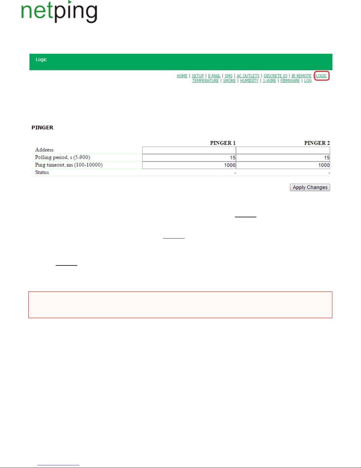
[ENG] 10.4. [DKSF 48.4 IU] How to Configure Pinger in the Module «Logic»?
To configure pinger, there is a need to go to the page « » of a device web interface:LOGIC
In the section « », it is possible to configure an availability checkup of a specified address via a network. A result of a checkup (a pinger status)Pinger
can be selected as an «input» for a logic rule. It is possible to learn how to configure a rule in the module « » from the section «Logic 10.2. [DKSF 48.8
». It is possible to configure no more than two pingers– « », « ». A typical use of a pinger isIU] How to Use the Module «Logic»? PINGER 1 PINGER 2
an automatic switching on a power supply of a backup equipment if a connection line failed.
where:
Address– is an IP address of a device, which is checked for availability. An empty line disables polling. : empty lineOn default
Polling period, s (5-900)–a value is selected taking into account how quickly a failure must be revealed. Also, there is a need to take into account that
too frequent switching of a power supply can decrease a wear out time of an equipment. If there is no response from ICMP echo (ping), it is repeated
after a timeout is over, and not when the next polling period starts. :15On default
Ping timeout, ms (100-10000) – is a time of waiting for a response to ping. A timeout is selected according to a speed of a local network and taking into
account a frequency of repeating unresponded pings. If there is no response to ping when a specified timeout is over, sending a ping is immediately
repeated. If there is no response after 5 repeated sending, a pinger status is changed to « », and repeats are stopped until the next pollingno response
period starts. :1000On default
Status– possible values are: « », « », « ». If polling is not finished, a status can be undefined. In this case rules, which depend on apinger responds silent status, does not form any commands, and their outputs are controlled by other rules or keep a previous status. A pinger status is updated
automaticallyapproximately 4 times a minute.
After setting values of a pinger, there is a need to click the button « ».Apply changes
After configuring a pinger, there is a need to configure a rule in the module « ». It is possible to learn how to do this from the section «Logic 10.2. [DKSF
».48.8 IU] How to Use the Module «Logic»?
If domain names are used, there is a need to take into account that because of a DNS server unavailability or absence of an IP address in
DNS settings, the module « » will not be able to determine an availability of a requested address. is switched to the status «Logic «Pinger» Sile
».nt
Copyright © NetPing east Co., Ltd E-mail: Phone:+886-2-23121582[email protected]
Page 91
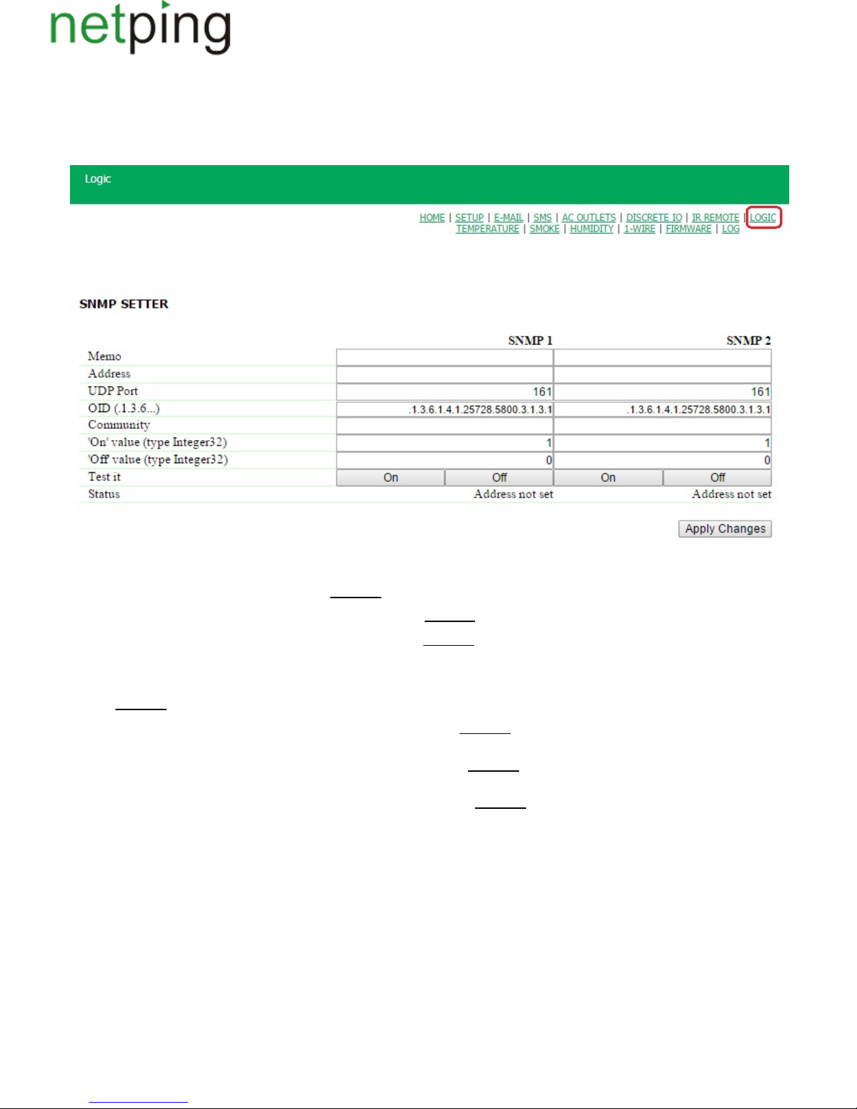
[ENG] 10.5. [DKSF 48.4 IU] What Is SNMP SETTER?
SNMP SETTER is used as an output of a rule of the module « » and is designed for setting an SNMP OID variable at a remote device via anLogic
SNMP v1 protocol. In particular, it is possible to control IO lines and relays of another NetPing device via a network.
To configure an SNMP SETTER, there is a need to go to the page « » of a device web interface:LOGIC
In the section « » the next parameters are configured:SNMP SETTER
Channel number («SNMP1»,«SNMP2»)– this number is indicated as a rule output.
Memo– is a random text up to 30 characters in length. :On default empty line
Address– is an IP address, to which an SNMPSET command will be sent. :On default empty line
UDP Port –is a port, which listens to an SNMP agents at a remote device. :161On default
OID (.1.3.6...) – is an identifier of a variable, which will be set at a remote device. There is a need to indicate a full OID in numerical notation, starting
from .1.3… A list of variables is in the MIB file from a device in a special format or in a documentation of a device. It is possible to use a free piece of
software or any similar software for convenient browsing the MIB file in an appearance of a tree and checking functions ofiReasoning MIB Browser
variables. :.1.3.6.1.4.1.25728.5800.3.1.3.1On default
Сommunity–is anSNMP Community of a record, configured at a remote device. : empty lineOn default
«On – » value (type Integer32) is a value, which will be recorded into the OID at a remote device when invoking the action « », by clicking the buttonOn
« » or through an output of a logic rule. Type of the value is 32-bit signed integer.On :1On default
Off value – « » (type Integer32) is a value, which will be recorded into the OID at a remote device when invoking the action « », by clicking the buttonOff
« », or through an output of a logic rule.Type of the value is 32-bit signed integer.Off : 0On default
Test it–when clicking the buttons « » or « », a device immediately sends corresponding requests with values « » or « ».On Off On Off
Status – several seconds after sending a request to set a variable in the field « » a result « » is displayed. This means that a confirmation isStatus ОК
received, and a variable is set successfully. « » means that confirmation is not received. It can be a result of an unavailability of a controlledTimeout
device, its failure, incorrect IP address, port or community. Othervariants mean that a response with an error code has been received, and its textual
explanation is displayed in a status line.
After changing the settings, click the button « ».Apply changes
After configuring an SNMP SETTER, there is a need to configure a rule in the module « ». It is possible to learn how to do this from the section «Logic
».10.2. [DKSF 48.8 IU] How to Use the Module «Logic»?
Copyright © NetPing east Co., Ltd E-mail: Phone:+886-2-23121582[email protected]
Page 92

[ENG] 10.6. [DKSF 48.4 IU] Reset Signal and Initial Statuses of Outputs
When firmware starts operation or when clicking the button « » at the page « » of a device web interface, outputs, controlled by the logicReset LOGIC
are set to the known initial status. On default, this status is « », or « ». Other statuses can be set using the rule at the page « », which usesoff logic 0 LOGIC
a reset signal « » at the input.RESET
5 seconds after a reset, the signal has the value « ». A rule with a condition « » works in the moment of reset. A rule with a condition « »logic 1 = 1 = 0
works 5 seconds after the moment of reset. Therefore, it is possible to form a 5-second external reset pulse at one or several outputs or provide a proper
sequence of a power supply to the external devices.
If a logic operation is stopped, the rules « », which correspond to completion of the signal « », will work after clicking theIf/while RESET = 0 RESET
control button « » at the page « » of a device web interface.Start LOGIC
Copyright © NetPing east Co., Ltd E-mail: Phone:+886-2-23121582[email protected]
Page 93
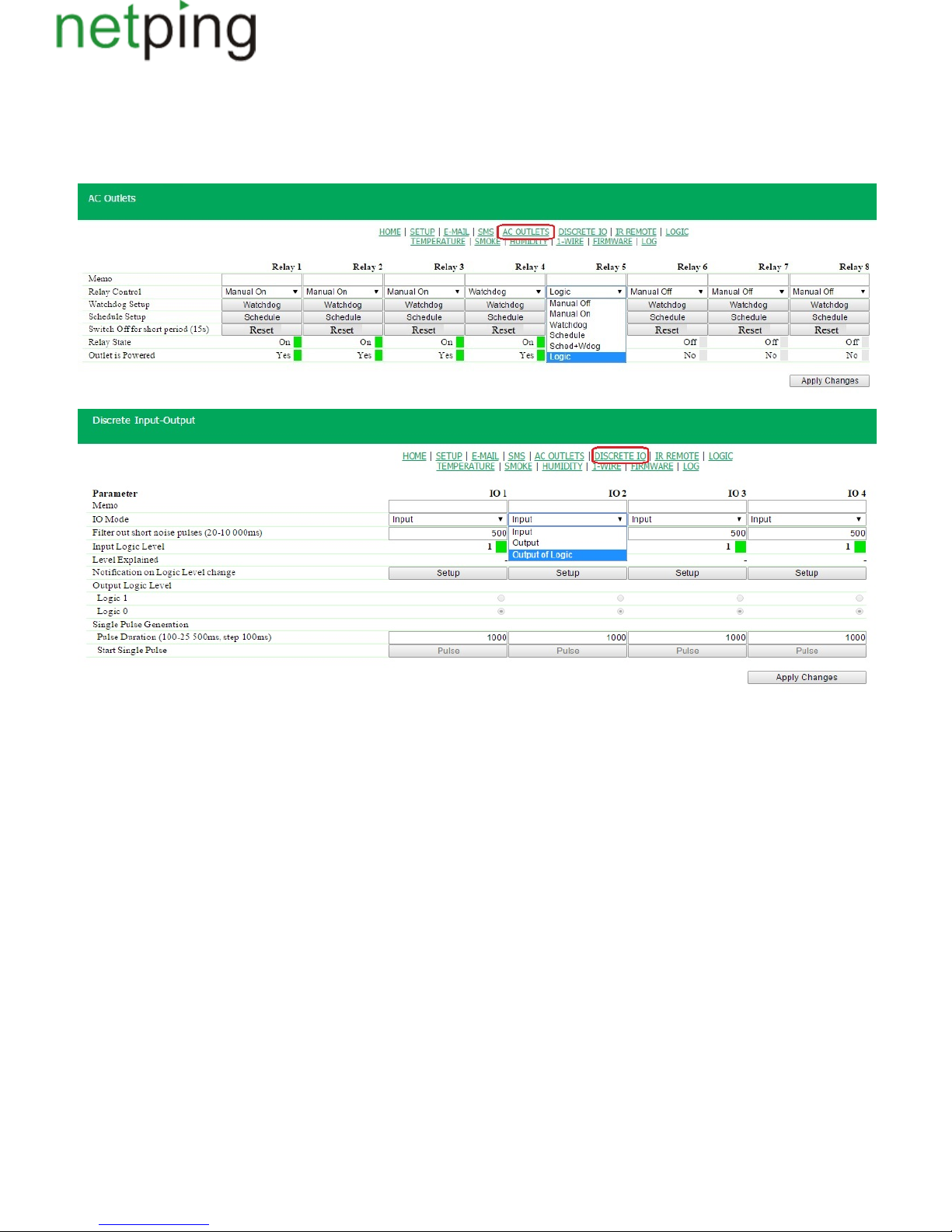
[ENG] 10.7. [DKSF 48.4 IU] Connecting Relays and IO Lines
Besides indicating a relay or an IO line as an « » of a rule of the module « », there is a need to indicate that the relay or the IO line will beoutput Logic
used together with the logic module.
Copyright © NetPing east Co., Ltd E-mail: Phone:+886-2-23121582[email protected]
Page 94

[ENG] 10.8. [DKSF 48.4 IU] IR Commands
It is possible to control a rule of the module « » by issuing an IR command through an external module . Before there is a need toLogic IRC-TR v2
record necessary commands from a remote (remotes) into the cells 1..4 of the module .IRC-TR v2
A rule « » initiates reproducing an IR command. The rule « » prohibits issuing an IR command. Rules of anotherIf … turn on While … keep turned off
type must not be used .together with an IR command
Copyright © NetPing east Co., Ltd E-mail: Phone:+886-2-23121582[email protected]
Page 95
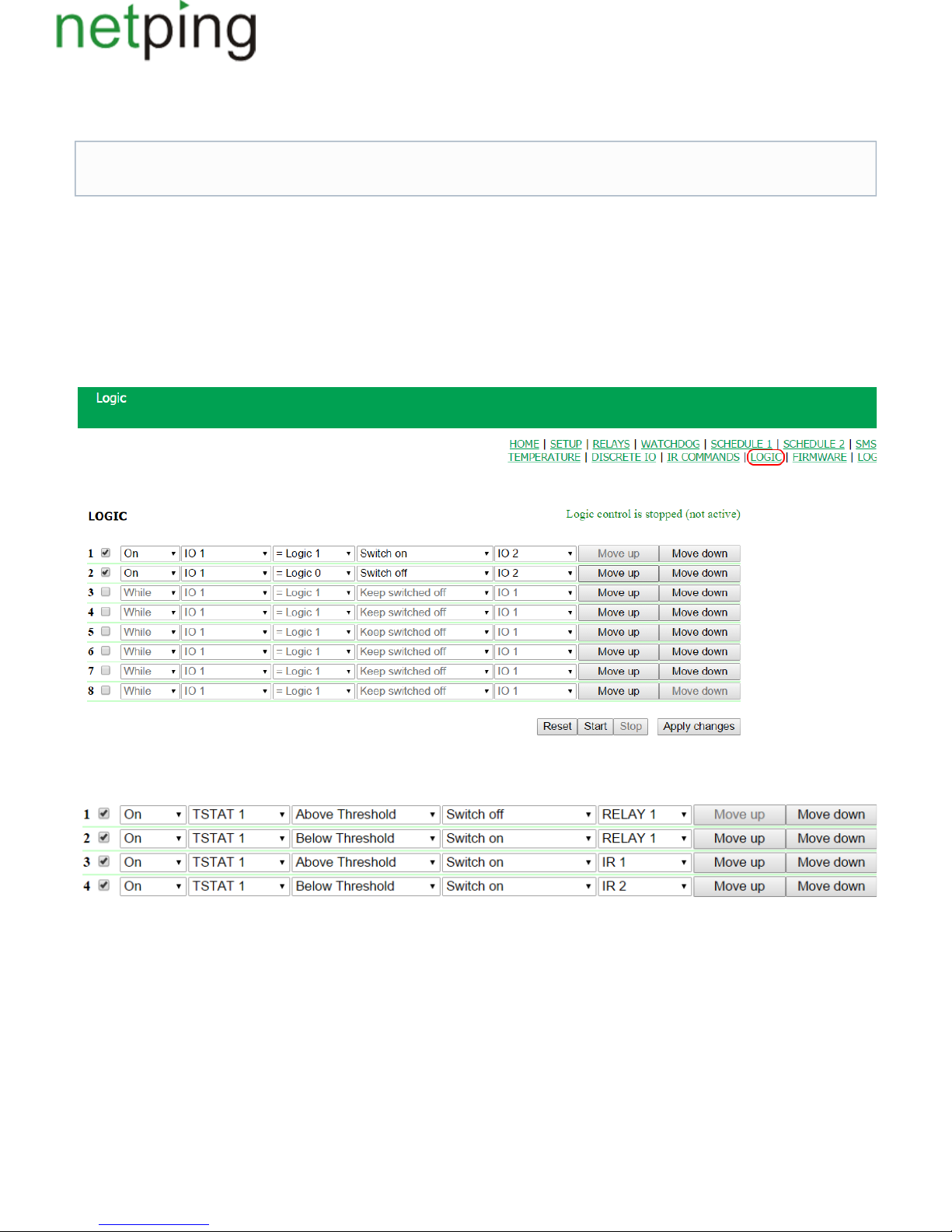
[ENG] 10.9. [DKSF 48.4 IU] Examples of Configurations of the Module «Logic»
At this page, several simplest examples of configuring the module .«Logic» are represented
Configuring a Thermostat
A NetPing device with a connected external temperature sensor allows to implement functions of a thermostat, supporting a specified range of
temperatures by turning on/off a device for heating and/or cooling in the automatic mode.
Task: It is necessary to maintain a temperature of 20°C indoors.
Solution: Let us suppose that an electric heater, which warms a certain room, is connected to a controllable socket . There is an№1 of a NetPing device
air conditioner in the room, which is managed by an external IR management module For automation of controlling a heater and an air.IRC-TR v2
conditioner to maintain a necessary temperature, there is a need to go to the page «LOGIC» of a device web interface:
There is a need to check checkboxes for first four rules and configure the next settings:
These rules mean that if a temperature in a thermostat 1 ) will exceed a specified one (i.e. above 20 ), an electric heater will be turned off(TSTAT1 °C
automatically ( ) and an air conditioner will be turned on the same automatically ( (rules №1 and №3). To avoid frequent turningRELAY 1 IR 1)
on/turning off a heater and an air conditioner, there is a switching hysteresis in a thermostat, which will be described below. If a temperature will fall
below a specified value, an air conditioner will be turned off ( ) and a heater will be turned on ( ) (rules №2 and №4).IR 2 RELAY 1
After setting up the rules, there is a need to click the button «Apply changes».
The next step is a configuration of the module «THERMO(HYDRO)STAT», on the basis of which previously configured rules will work:
It goes without saying, necessary sensors, are already connected to NetPing devices and NetPingas well as external management modules,
devices are previously configured for performing their specific tasks.
Copyright © NetPing east Co., Ltd E-mail: Phone:+886-2-23121582[email protected]
Page 96
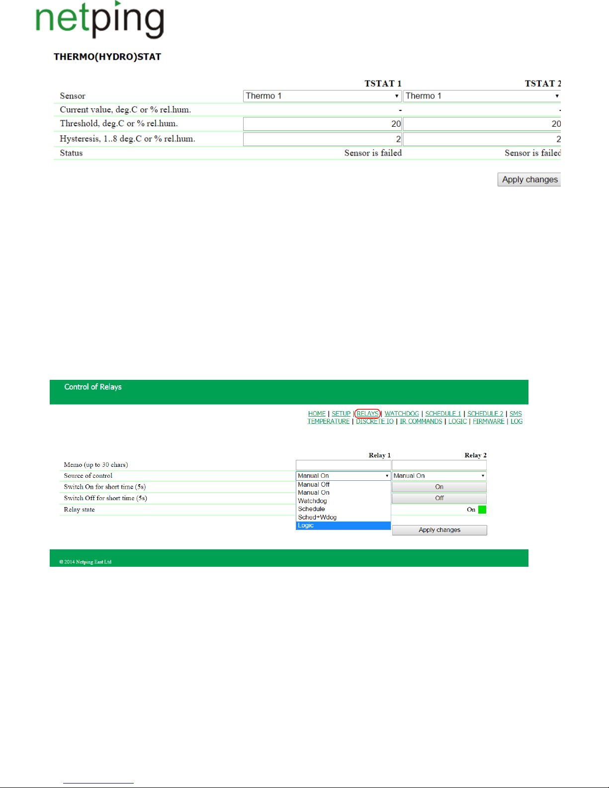
A temperature sensor №3 is used to measure a temperature indoors. In the module «THERMO(HYDRO)STAT» there is a need to configure TSTAT1
by choosing a sensor №3 from a drop-down list. Then specify a threshold of 20°C and a switching hysteresis of 2°C.
A hysteresis sets a «corridor» around a specified temperature, within which a thermostat does not respond to temperature fluctuations. This function
allows to avoid frequent random switching of a heater (a cooler) caused by natural spontaneous fluctuations of a temperature measured by a
temperature sensor.
If a current status of a thermostat is « », then a threshold for switching a status is a specified temperature minus a hysteresis value. And vice versa,above
if a current status is « », then a threshold for switching is a specified temperature plus a hysteresis value. As soon as a temperature falls or rises andbelow
reaches a threshold value including hysteresis thus leaving the limits of «corridor», a status of a thermostat is changed to the opposite one.
After configuring a thermostat, there is a need to click the button «Apply changes».
Recording, saving and replaying IR commands to control an air conditioner is indicated in the corresponding section of a user guide (works for devices
supporting an IR control module ).IRC-TR v2
Except indicating a relay as an «output» of a rule, there is a need to indicate that this relay will be used together with a logic module. To do this, there is
a need to go to the page «220V MANAGEMENT» of a device web interface and choose a management mode « »:Logic
After changing a management mode, there is a need to click the button «Apply changes».
The last step of configuration is starting logic on a corresponding page of a web interface by clicking the button «Start»:
Copyright © NetPing east Co., Ltd E-mail: Phone:+886-2-23121582[email protected]
Page 97
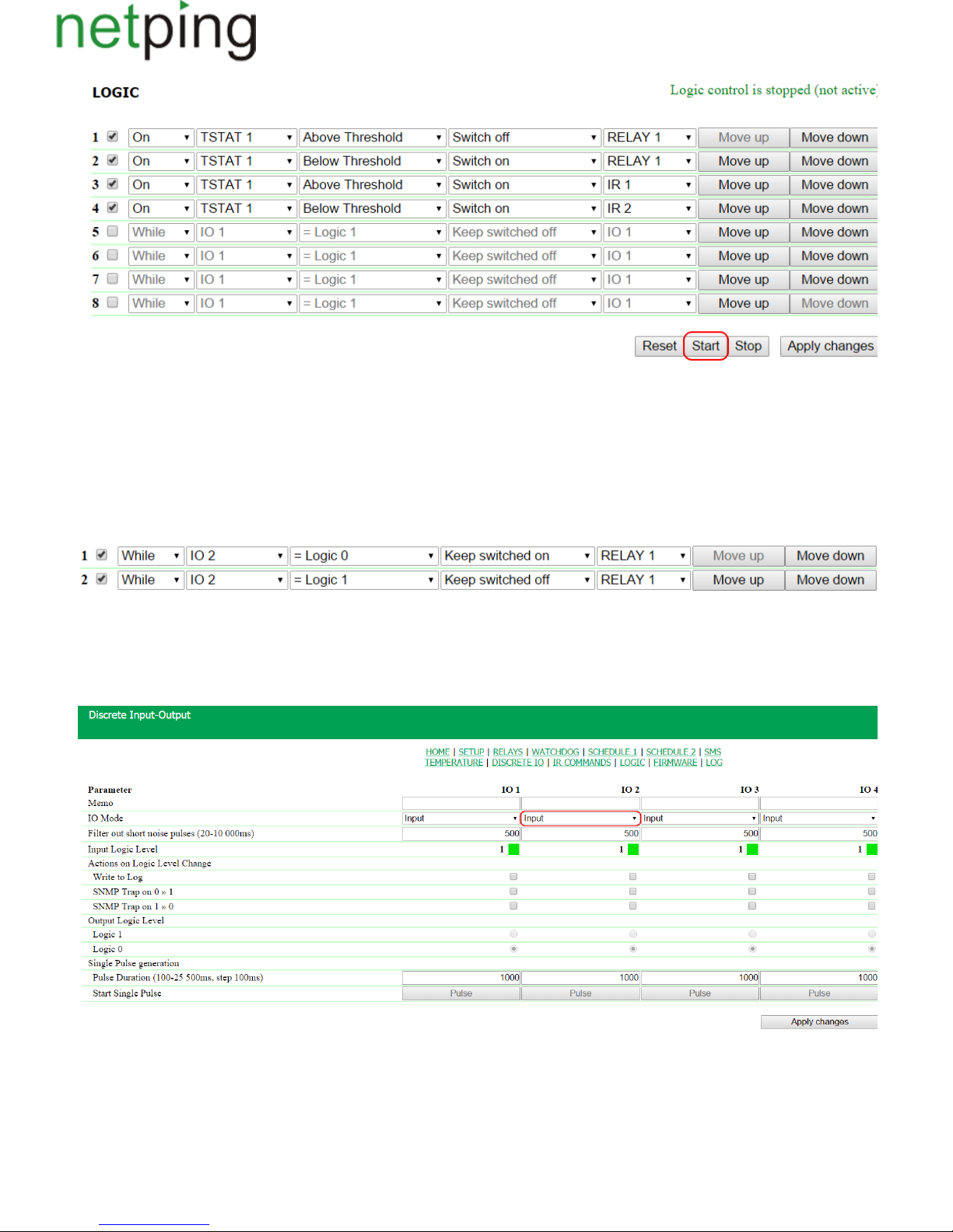
Example of Warning Alarm When a Shock Sensor Triggered
A NetPing device, to which and are connected, can perform security functions for remote objects and closetsshock sensor PI-90D siren alarm АС-10
with equipment.
Organising a warning alarm for a remote control of a security guard when breaking a wiring closet with equipmentTask: .
Let us suppose that , is connected to the IO line №2 of a NetPing device,Solution: shock sensor PI-90D, which is installed into a closet with equipment
while 1. To configure NetPing for securitysiren alarm АС-10, which is displayed at a remote control of a security guard, is connected to the Relay
measures, there is a need to set the next rules in the module «Logic»:
These rules mean when theshock sensor PI-90D (IO 2) triggers, then a warning alarm АС-10 (RELAY 1) will be activated (rule №1) until a level of an
IO line №2 has got a value «logic 1» (rule №2).
After setting up rules, there is a need to click the button «Apply changes».
The next step is a necessity to configure an operation mode of an IO line at the page «INPUT-OUTPUT» of a device web interface. An IO line must
work in the mode input« »:
Besides indicating a relay as an «output» for a rule, there is a need to specify that this relay will be used together with a logic module. To do this, there is
a need to go to the page «220V MANAGEMENT» of a device web interface and choose a relay management mode « »:Logic
Copyright © NetPing east Co., Ltd E-mail: Phone:+886-2-23121582[email protected]
Page 98
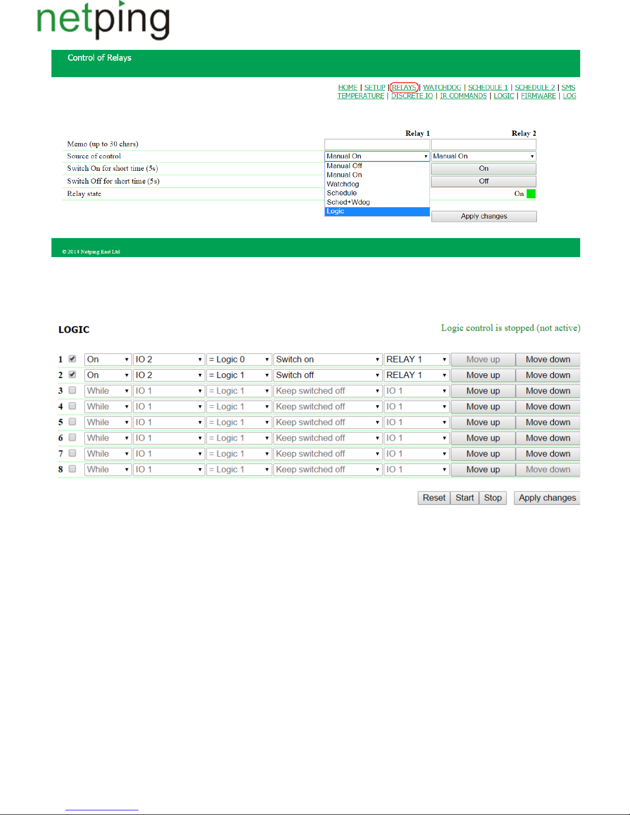
After choosing a source of control for a relay, there is a need to click the button «Apply changes».
The last step of configuration is starting logic at the corresponding page of a web interface by clicking the button « »:Start
Copyright © NetPing east Co., Ltd E-mail: Phone:+886-2-23121582[email protected]
Page 99

[ENG] 11. [DKSF 48.4 IU] Working with IR Control Module
Copyright © NetPing east Co., Ltd E-mail: Phone:+886-2-23121582[email protected]
Page 100
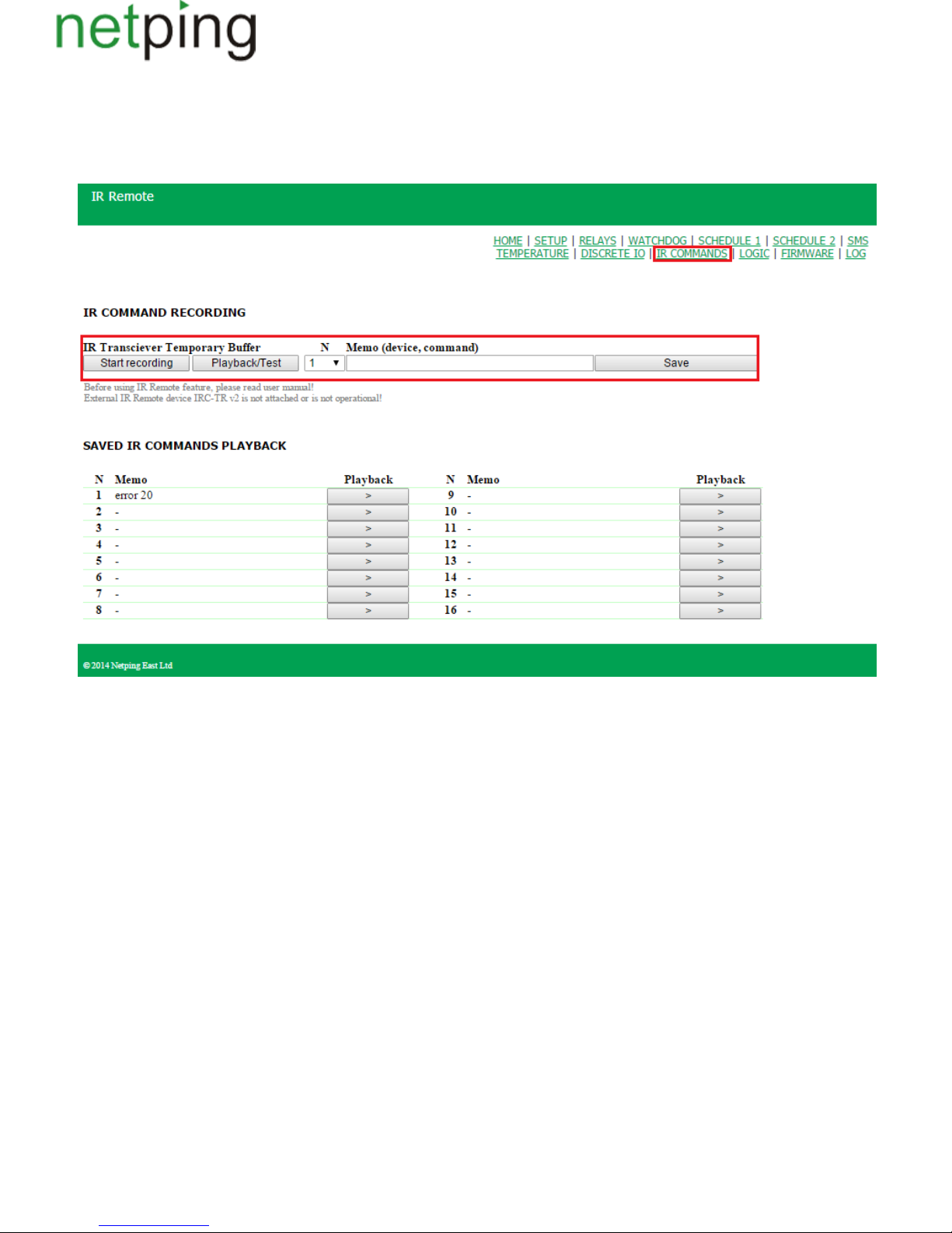
1.
2.
3.
4.
5.
6.
[ENG] 11.1. [DKSF 48.4 IU] How to Record IR Commands Properly?
An IR Control module works with an IR transceiver IRC-TR v2. The transceiver can record and reproduce IR signals from remote controls of home
appliances.
To record IR commands, there is a need to go to the page « » of a device web interface:IR COMMANDS
New IR commands are recorded in the section« »:IR COMMAND RECORDING
Prepare an IR remote, from which it is necessary to capture a command.
Make sure that a red LED on the IR transceiver glows steadily
Choose a command number « » and enter its description into the field « ».N Memo (device, command)
Click the button « ». Send a command from an IR remote 30 seconds after clicking the button « ». Otherwise, aStart recording Start recording
transceiver will go to a standby mode. A remote and a transceiver must be disposedcoaxially at the distance of 10-30 cm for an «eye» of a
transceiver to see a transmitting IR LED of a remote.A command will be recorded.
Check a recorded command by clicking the button « ».Play/Test
Click the button « » to save a command in a nonvolatile memory if a command is successfully reproduced.Save
It is desirable to check again the operation of an IR command by clicking a corresponding button « » in the section of saved commands.>
Copyright © NetPing east Co., Ltd E-mail: Phone:+886-2-23121582[email protected]
 Loading...