

Page 1
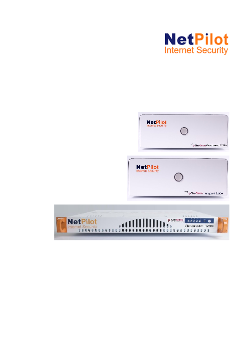
NetPilot
™
Range
Getting Started Guide
NetPilot Internet Security Limited
November 2009
Page 2

NetPilot Internet Security limited. All rights reserved. No part of this
documentation may be reproduced in any form or by any means or used to make
any derivative work (such as translation, transformation, or adaptation) without
permission from NetPilot Internet Security Limited.
NetPilot Internet Security Limited reserves the right to revise this documentation
and to make changes to its content from time to time without obligation on the
part of NetPilot Internet Security Limited to provide notification of such revision or
change.
NetPilot Internet Security Limited without warranty of any kind, either implied or
expressed, including, but not limited to, the implied warranties of merchantability
and fitness for a particular purpose. NetPilot Internet Security Limited may make
improvements or changes in this product(s) and/or the program(s) described in
this documentation at any time.
Unless otherwise indicated, NetPilot Internet Security Limited registered
trademarks are registered in the United Kingdom and may or may not be
registered in other countries. NetPilot Internet Security, NetPilot, IBX and
Boundary Caching are trademarks of NetPilot Internet Security Limited.
CompuServe is a registered trademark of CompuServe, inc. Novell, NetWare
and Yes NetWare are registered trademarks of Novell Inc. Windows, Windows
95, Windows 98, Windows 2000, Windows XP and the Windows logo are
registered trademarks of Microsoft Corporation. VT100 is a registered trademark
of Digital Equipment Corporation. Other brand and product names may be
registered trademarks or trademarks of their respective holders.
Under no circumstances will NetPilot Internet Security be deemed liable for any
Internet call connection costs whatsoever. It is solely the responsibility of the
installer and owner of any and all the devices to ensure correct installation and
correct on-going use.
Environmental Statement:
It is NetPilot Internet Security Limited’s policy to be environmentally friendly in all
its operations. This manual is printed on paper that comes from sustainable,
managed European forests. The production process for making the pulp has a
reduced AOX level (adsorbable organic halogen) resulting in elemental chlorinefree paper.
This paper is fully biodegradable and recyclable.
NIS-NetPilot-GS-001
Page 3

Contents
Getting Started – New NetPilot Range 1
Contents
Contents...............................................................................1
Using this Guide...................................................................3
Text Conventions in This Guide............................................................3
Support..................................................................................................4
Product Pack contents ........................................................5
Choosing a location for installation ....................................7
Installation Requirements......................................................................7
Rack installation....................................................................................8
Connecting the Power Cable..............................................................10
Getting to know NetPilot ...................................................11
Power Switch ......................................................................................11
Front and Rear panels - NetPilot Guardsman ...................................12
Front and Rear panel NetPilot Vanguard - Desktop...........................13
Front and Rear panel NetPilot Vanguard – Rackmount ..................... 14
Front and Rear panel NetPilot Globemaster.......................................14
Front and Rear panel NetPilot Globemaster.......................................15
Installation.........................................................................17
Power connection................................................................................17
LAN connection...................................................................................17
Connecting to a hub or switch.........................................................17
Connecting to a single PC...............................................................17
Internet connection..............................................................................18
Connecting via an Ethernet cable/ADSL.........................................18
Powering on........................................................................................19
Powering off........................................................................................19
Configuring the NetPilot unit.............................................20
NetPilot Connection Configuration......................................................20
Manual configuration of LAN2 for Internet access..........................21
Technical Information........................................................22
Interface Specifications.......................................................................22
Page 4

Contents
Getting Started – New NetPilot Range 2
Physical Specifications........................................................................23
European Approvals...........................................................24
EMC Directive Compliance.................................................................24
CE Certification...................................................................................24
General Safety Information ...............................................25
Important Safety Information ............................................27
Importante notice de Sécurité.............................................................28
Wichtige Sicherheitshinweise .............................................................29
Informazioni di Sicurezza importanti...................................................30
Información de Seguridad importante.................................................31
Additional Safety Information..............................................................32
Page 5
Using this Guide
Getting Started – New NetPilot Range 3
Using this Guide
Throughout this guide, blocks of text may be accompanied by an icon
and printed in bold or italic type. These blocks are Warnings, Cautions
and Notes and are used as follows:
WARNINGS and CAUTIONS: contain directions that
you must follow for your personal safety. Follow all
instructions carefully.
NOTES: These comments are to advise you of
important information that helps you make better use
of your product.
Text Conventions in This Guide
The examples below identify and explain specially formatted text that is
used throughout this guide.
Key names appear in a boldfaced type, very much the way they
appear on the keyboard; for example, Home, End, Backspace,
Tab.
When keys must be pressed at the same time, the action is
represented by the key names and the plus (+) symbol; for
example, Ctrl+Alt+Delete.
Drive letters that are not in command lines are presented in
uppercase type as shown here: drive A.
Software directory names or folders that are not in command
lines are presented in uppercase type as shown here:
DIRECTORY.
The file names are presented in uppercase italic type as shown
here: FILENAME.
The names of commands are presented in lowercase, bold italic
type as shown here: install, or a:\install. Commands that are to
be entered at the system prompt may be shown on a separate
line.
Page 6

Using this Guide
Getting Started – New NetPilot Range 4
The names of items on the desktop are presented in a boldfaced
type. For example, you are directed to "double-click on the My
Computer icon on the desktop". The names of software
programs and items on the menu bar are also presented in a
boldfaced type. For example, you are directed to "choose Start,
then Programs, then Internet Explorer from the menu bar".
When you need to type information without pressing the Enter
key, you are directed to "type" the information.
When you need to type information and press the Enter key, you
are directed to "enter" the information.
Support
Technical support issues are covered in greater depth in our ‘How to’
documents available in our Support section on www.NetPilot.com,
which we update regularly.
The latest version of software can also be downloaded directly from our
website to a PC on your network then transferred to the NetPilot. We
recommend that you check this site for the latest upgrades.
To enable you to download upgrades, you must have first registered your
unit, and this can also be done on the same web site.
NB: For first line telephone support, please contact your NetPilot
supplier.
Page 7

Pack Contents
Getting Started – New NetPilot Range 5
Product Pack contents
Before installing the NetPilot please check the pack contents. Your
NetPilot pack should contain depending on model type:
NetPilot Guardsman with Dual Ethernet interfaces
NetPilot Guardsman unit.
Power cable with appropriate plug for the national power supply.
Cable pack.
NetPilot Getting Started Sheet.
NetPilot Vanguard with Triple Ethernet interfaces
NetPilot Vanguard unit.
Power cable with appropriate plug for the national power supply.
Cable pack.
NetPilot Getting Started Sheet.
NetPilot Globemaster (rack mountable or tower unit) with Triple
Ethernet interfaces
NetPilot Globemaster 19” rack mountable unit with rack fixing pack
or tower unit
Cable pack with appropriate plug for the national power supply.
Cable pack.
NetPilot Getting Started Sheet.
If any of the items have been damaged in transit or are missing,
contact the NetPilot Internet Security Limited reseller from whom the
equipment was purchased.
Page 8
Installation
Getting Started – New NetPilot Range 6
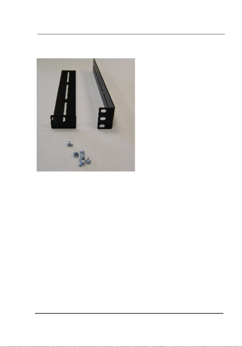
Picture below shows rack fixing pack
Page 9

Installation
Getting Started – New NetPilot Range 7
Choosing a location for installation
When installing your NetPilot ensure:
It is accessible and cables can be easily connected.
Ensure the unit is placed on a cool surface.
It is out of direct sunlight and away from sources of heat.
Cabling is away from power lines, fluorescent lighting fixtures
and sources of electrical noise such as radios, transmitters and
broadband amplifiers.
Water or moisture should not enter the case of the unit.
Airflow around the unit and through the vents in the side of the
case is not restricted. We recommend that you provide a
minimum of 25 mm (1 inch) clearance around the unit.
Do not rest objects directly on top of the unit.
Installation Requirements
The following items are needed in order to install the NetPilot:
A suitable cable for connection to the LAN or workstation (if only
a workstation is attached to the unit).
For connecting to a remote site over an ADSL modem or a
leased line, a suitable Internet cable is required.
Page 10
Installation
Getting Started – New NetPilot Range 8
Rack installation
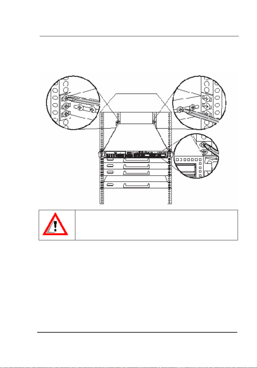
The NetPilot Globemaster can be mounted in a rack using the supplied
rack mounting kit which contains:
Mounting Brackets x 2
Screws x 6
Follow these instructions to mount the unit into an industry standard 19"
rack:
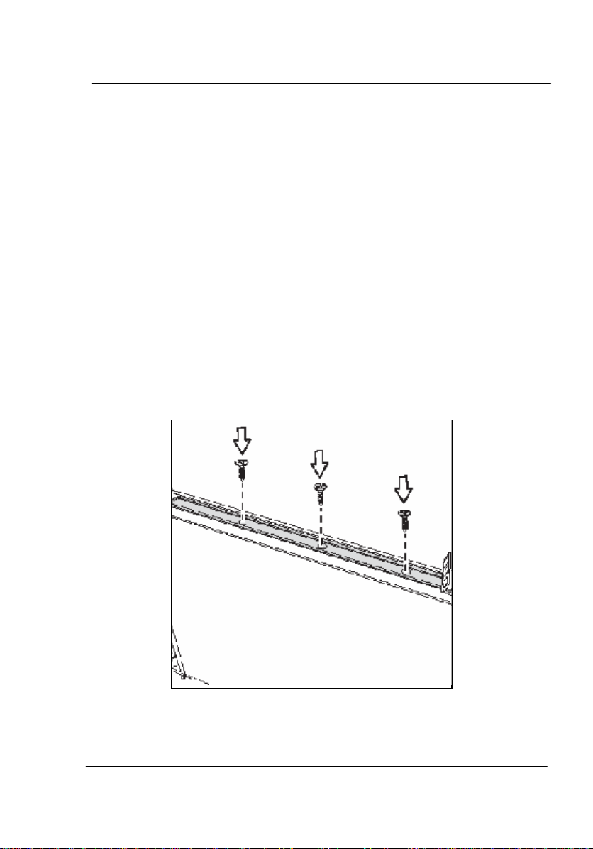
The NetPilot Globemaster is shipped with a set of brackets for
mounting in a 19” Rack system. Along the Enterprise unit
openings are provided to which the brackets can be fasten.
Slide the brackets along the unit until they are in a suitable
position and then screw in three of the supplied screws on each
side.
Page 11
Installation
Getting Started – New NetPilot Range 9
Lift the unit into place in the rack and screw it into place as
shown.
To avoid injury, it is strongly recommended that one person lift
the NetPilot Globemaster in place while a other person screws
it to the rack.
Page 12

Installation
Getting Started – New NetPilot Range 10
Connecting the Power Cable
First, read the chapter “General Safety Information”.
Do not have any power supply connected to the unit
until you have installed the unit into its final location.
Ensure any on/off power switches at the outlet socket
are set to their ‘OFF’ positions.
The following steps are necessary to connect the device with mains:
o Connect the power lead to the power connector on the rear
panel of the NetPilot.
o Plug the mains plug of the power lead into a standard mains
wall socket, but DO NOT switch it on yet.
o NetPilot needs to be connected to your local area network
(LAN) as well as the Internet via a suitable wide area
network (WAN) connection.
Page 13

Installation
Getting Started – New NetPilot Range 11
Getting to know NetPilot
Power Switch
It is advisable to shut down the system under software control to
guarantee that any open files on the system disk are closed correctly. In
order to power down the NetPilot in the recommended manner, the
power switch on the front panel provides a signal to the main processor
to begin the shutdown procedure. This process is indicated by beeps
which will indicate the start and end of the shutdown. After a period, the
front panel indicator LEDs will go out, the fans will stop and the power
lead may be removed from the NetPilot. If the power lead is removed
without using the power switch or there is a mains power failure, the
NetPilot may have to rebuild any of the files that were open which will
result in the next power-up taking more time.
Page 14
Installation
Getting Started – New NetPilot Range 12
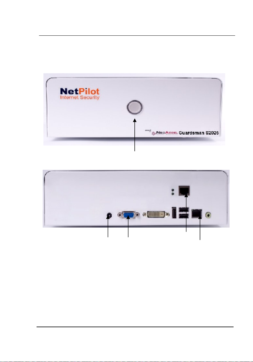
Front and Rear panels - NetPilot Guardsman
Monitor
LAN2
LAN1
Power Switch
Power Inlet
Page 15
Installation
Getting Started – New NetPilot Range 13
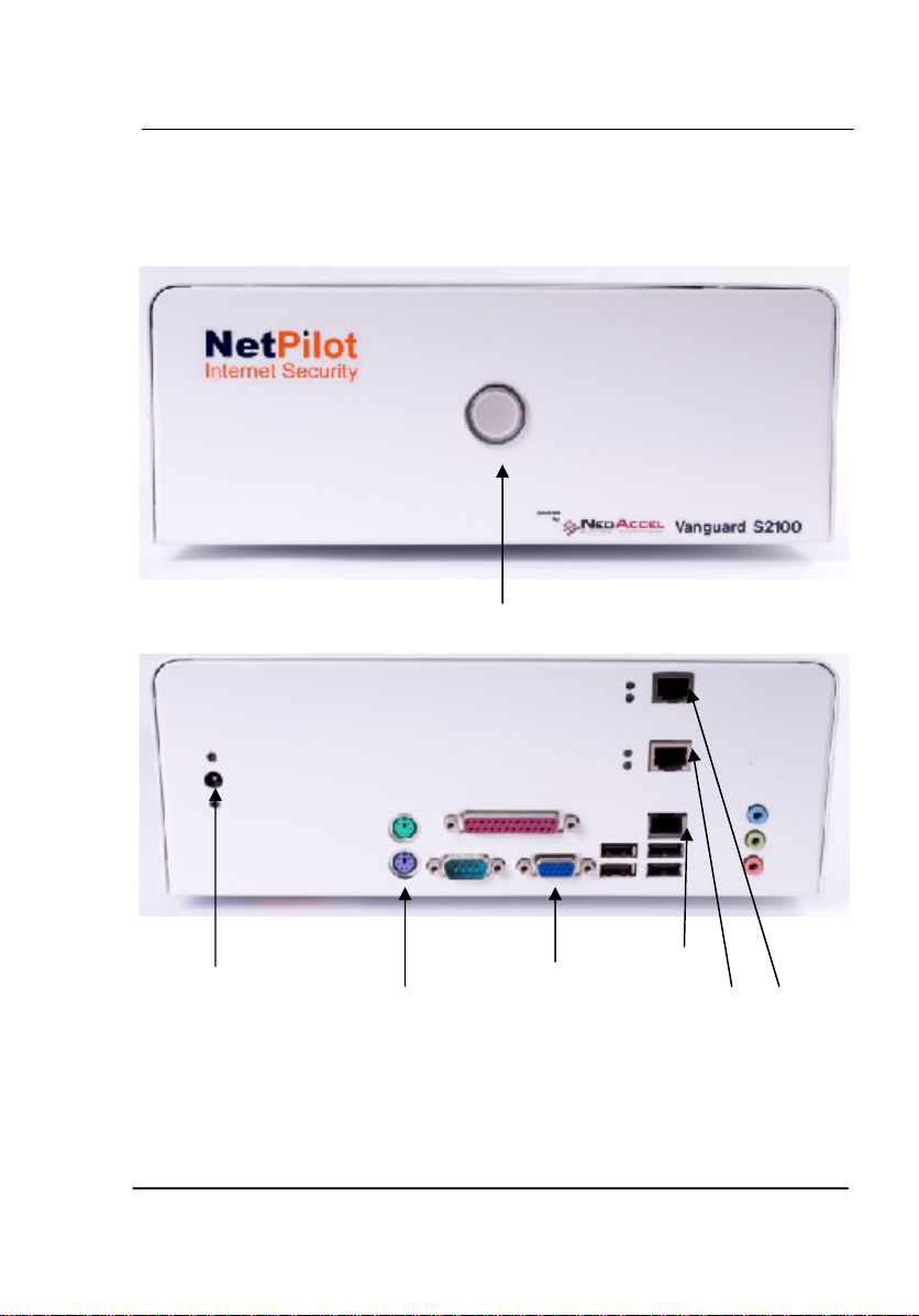
Front and Rear panel NetPilot Vanguard - Desktop
Keyboard
Monitor
LAN3
LAN2
Power Switch
Power Inlet
LAN1
Page 16
Installation
Getting Started – New NetPilot Range 14
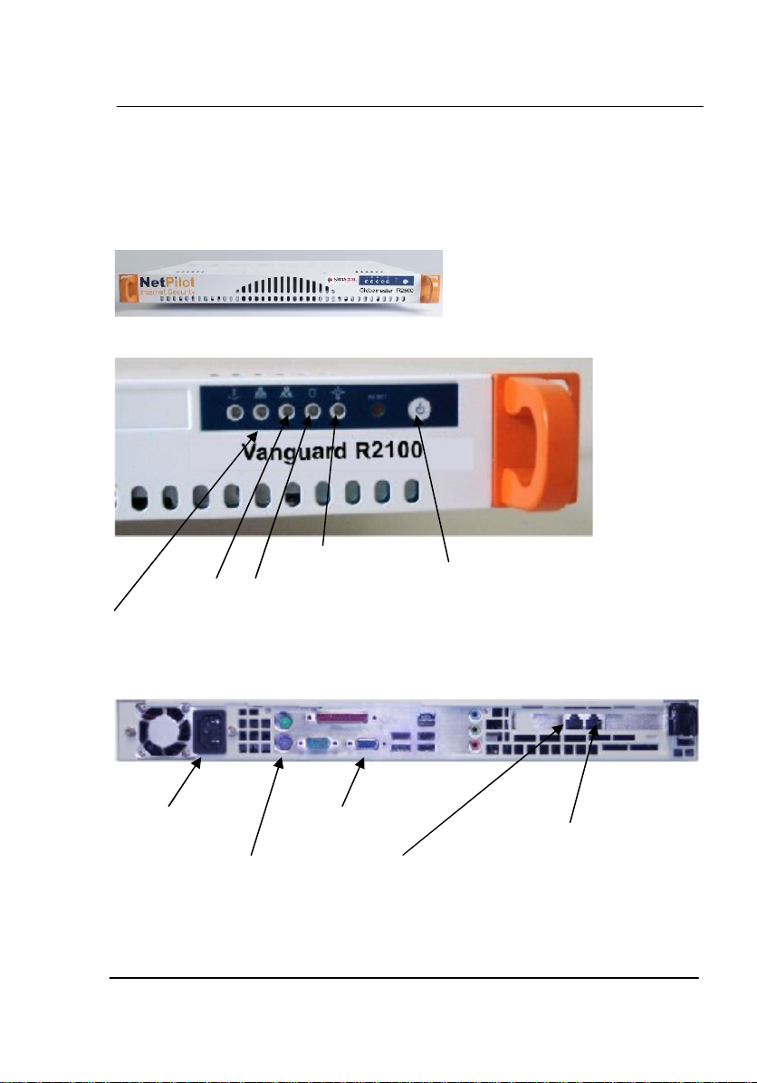
Front and Rear panel NetPilot Vanguard – Rackmount
LAN1 - for Local LAN
VGA Monitor
Power
Keyboard
LAN2 - for Internet
LAN3 - for DMZ
ON/OFF Button
Power
LED
Disk
LED
LAN1
LED
LAN2
LED
Page 17
Installation
Getting Started – New NetPilot Range 15
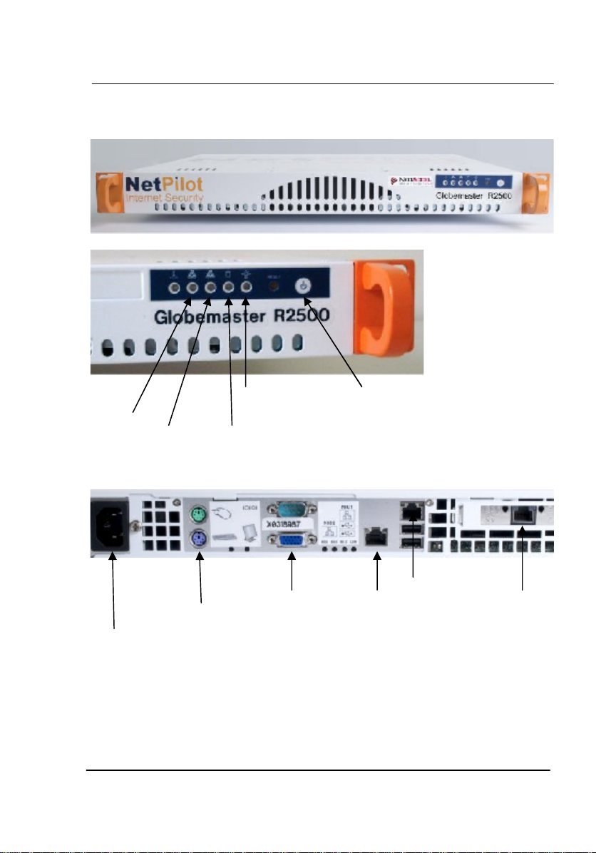
Front and Rear panel NetPilot Globemaster
POWER The electrical mains system input. For power requirements
see table in ‘Technical Information’ section.
Power Provides the unit with switched standby mode for safe
switch power down of the unit.
Power Inlet
LAN1
LAN3
LAN2
Monitor
Keyboard
ON/OFF Button
Power LED
Disk LED
LAN1
LED
LAN2
LED
Page 18
Installation
Getting Started – New NetPilot Range 16
Caution:
Do not disconnect electrical power from the NetPilot until shut
down is completed.
Only use the power cable supplied with the unit to connect to the
mains power supply. Do not use any other power cable with this
unit. If the plug on the power cable does not match the mains inlet
socket, contact your reseller for further advice.
LAN 1 The 10/100 or 10/100/1000 Ethernet Base-T interface is an
RJ45 socket.It allows direct connection between the
NetPilot and a single piece of equipment. The Ethernet LAN
port simulates the characteristics of a workstation port. This
allows it to be directly connected to a LAN or network hub
port as required.
LAN 2 The 10/100 or 10/100/1000Base-T interface is an RJ45
socket and it is recommended as the connection to an
outside network i.e. Internet. It allows direct connection
between the NetPilot and a single piece of equipment for
example ADSL router or a LAN or network hub port as
required.
LAN 3 10/100 or 10/100/1000 Base-T interface with an RJ45
socket. NetPilot V6 software this is a configurable port for
DMZ or additional LAN use.
Monitor Initial Configuration and diagnostic use only
Keyboard Initial Configuration and diagnostic use only
N.B. All other ports are for diagnostic or future use and not
customer configurable or usable.
Page 19
Installation
Getting Started – New NetPilot Range 17
Installation
Power connection
Connect the power lead provided to the power connector on the rear
panel of the NetPilot and to a standard mains wall socket.
Do not switch on at this stage.
Only use the power cable supplied with the unit to connect to the
mains supply. Do not use any other power cable with the NetPilot.
If the plug on the power cable does not match the mains socket,
contact your supplier for further advice.
LAN connection
The connection to the 10/100 or 10/100/1000 Base-T Local Area
Network (LAN) may be to a hub or switch, or for diagnostic purposes
directly to a single workstation or PC.
Do not connect an ISDN line to a NetPilot LAN port. The ISDN
voltage can damage the unit.
Connecting to a hub or switch
1. Connect either end of the supplied cable to the LAN 1 socket on the
NetPilot.
2. Connect the other end of the cable to a hub or switch port.
Connecting to a single PC
1. Connect either end of the cable to the LAN 1 socket on the NetPilot.
2. Connect the other end of the cable to the socket on the PC’s
Ethernet adaptor:
Page 20

Installation
Getting Started – New NetPilot Range 18
Internet connection
If the NetPilot is supplied in addition to LAN2 with one additional or more
LAN interfaces then only one may be selected to operate as the default
Internet connection at any one time.
Connecting via an Ethernet cable/ADSL
1. Connect either end of supplied cable to the LAN 2 socket on the
NetPilot.
2. Connect the other end of the cable to the routing device.
If the router to which the NetPilot is connected provides DHCP services
the NetPilot will automatically obtain the IP addresses necessary to set
up an Internet connection.
Otherwise you will have to configure your connection setting manually in
Network > Connectors using static IP addresses. The LAN2 port address
should be within the IP address range allocated on the LAN side of the
routing device; and not used by any other device. The Gateway address
will be the IP address already allocated to the LAN side of the routing
device that connects, directly or indirectly, to the Internet.
Page 21

Installation
Getting Started – New NetPilot Range 19
Powering on
You can now power-on the NetPilot. Remember that the power-on
sequence can take up to three minutes. It is completed when a final
audible bleep is given.
Powering off
As with any computer that includes a disk, when the NetPilot is shut
down it is desirable that the software is able to close any open files on
the disk correctly, before the power is removed. To achieve this, go to
the Power > Shutdown screen on the MMI and perform a shutdown or
depress the power switch on the rear or the front of the machine to the
off position. You must wait for the final audible beep noise and all LED
activity to finish prior to removing the power cable. This should take
around two minutes to complete.
Page 22
Technical Information
Getting Started – New NetPilot Range 20
Configuring the NetPilot unit
NetPilot Connection Configuration
After connecting NetPilot to your network, and completing all other
installation instructions in the previous chapter, you may switch on your
NetPilot. When NetPilot issues its final ready beep (this could take up to
three minutes) it is ready for you to configure. This can be done using the
Internet browser of any PC on the same network as NetPilot. Initially
the NetPilot’s LAN1 and LAN2 interfaces are set to ‘Quick configuration’
profile, allowing the unit to pick up you network configuration. Please
always make sure that during the installation you change this to a profile
suitable for your LAN interfaces.
Once the browser has been started then type http://netpilot into the
browser location window.
If you cannot access NetPilot, please refer to the Support section
on the www.NetPilot.com website
The NetPilot’s Internet Connection will be automatically established, if
LAN2 has been connected to a DHCP server during installation.
NetPilot Internet Security recommends that even if you intend to set
up the Internet connection manually, you should allow the NetPilot
to configure itself automatically, if access to a DHCP server is
available. This will establish that the unit is working correctly and
access to online help and documentation will be provided instantly.
The use of static IP addresses requires manual Connectors
configuration.
Page 23
Technical Information
Getting Started – New NetPilot Range 21
Manual configuration of LAN2 for Internet access
The manual configuration of all NetPilots interfaces is available in
Network > Connectors section of the command interface. Once you
have accessed this screen you will need to change the setting of LAN2
connector from Quick Configuration WAN to Ethernet router, press
Edit and progress to the network profile in the main Connectors screen.
In there firstly proceed to edit the Ethernet Router Profile, where you
have to enter your IP address for the LAN2 port and its subnet mask.
Once this is set, secondly add the Default Route by entering the
Gateway IP address of the routing device you are using and checking
the default route box. Confirm your settings by clicking ok when
requested as well as within the Connectors section itself.
If you have a DHCP server on your router and want the NetPilot to act
as a DHCP client select Ethernet Cable / ADSL as the profile for the
LAN2 connector in Network > Connectors and click ok till the new
setting is accepted.
If you require information on how to configure the Windows Client,
Windows Mail settings, DHCP and fixed IP addresses please refer to
documents in the Knowledge Base section within NetPilot Internet
Security’s SmartStore database under http://smartstore.NetPilot
Internet Security.net/.
By default, the LAN1 IP Address is set to 10.0.0.1. This can be
configured to a different range.
Step by step instructions with screen shots are available in
‘How to – manual configuration’ http://smartstore.NetPilot Internet
Security.net/index.asp?297866.
Page 24

Technical Information
Getting Started – New NetPilot Range 22
Technical Information
Interface Specifications
LAN 1
10/100 or 10/100/1000 Base-T interface with an
RJ45 connector socket for UTP local LAN
connectivity
LAN 2
10/100 or 10/100/1000 Base-T interface with an
RJ45 connector for WAN Internet connection.
LAN 3
10/100 or 10/100/1000 Base-T via an RJ45
connector socket for UTP
Other ports
Not used by the NetPilot operating system, or for
diagnostics only. Not customer configurable or
usable.
Page 25
Technical Information
Getting Started – New NetPilot Range 23
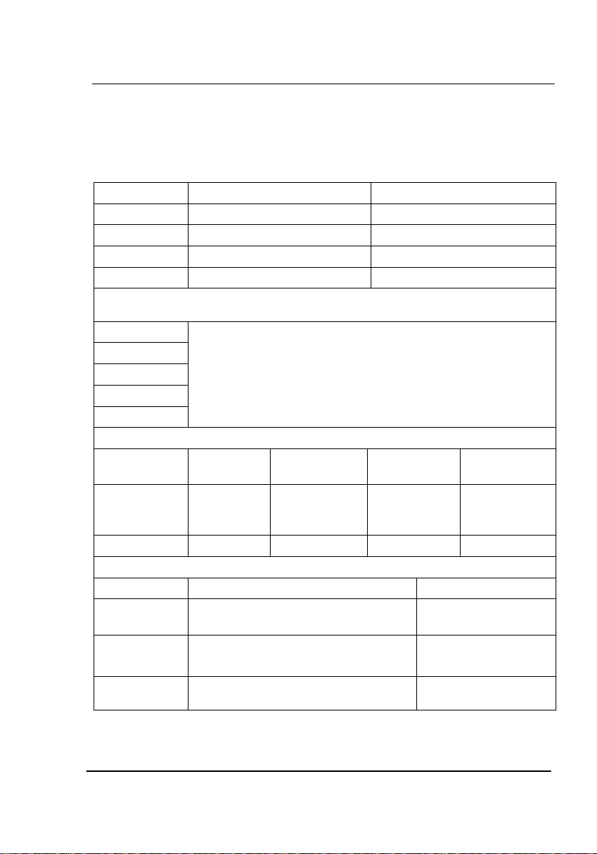
Physical Specifications
Dimensions
NetPilot Guardsman - Desktop
NetPilot Vanguard - Desktop
Width
263mm (10.4“)
263mm (10.4“)
Height
75 mm (2.95“)
100 mm (3.9“)
Depth
206 mm (8.1“)
206 mm (8.1“)
Weight
2.45kg (5.4 lbs)
2.55kg (5.6lbs)
Dimensions Rackmount models
NetPilot Globemaster or rackmount version of NetPilot Vanguard
Width
Height
Depth
Weight
Rack mount unit
426 mm (16.77“)
43 mm (1.7“)
356 mm (14.00“)
9.3 kg (20 lbs)
Power Requirements
Guardsman
Vanguard
Desktop
Vanguard
Rackmount
Globemaster
Supply
100 – 240 V
AC, 50 – 60
Hz
100 – 240 V
AC, 50 – 60 Hz
100 – 240 V
AC, 50 – 60
Hz
100 – 240 V
AC, 50 – 60 Hz
Consumption
2A Max
2A Max
5A Max
5A Max
Environmental Considerations
Operating
Storage
Relative
Humidity
20% to 50%,
non-condensing
20% to 50%,
non-condensing
Temperature
Range
10°C to +35°C
(50 - 95°F)
-10 to +50°C
(14 - 120°F)
Maximum
Altitude
3,000m (9843 ft)
3,000m (9843 ft)
Page 26

Technical Information
Getting Started – New NetPilot Range 24
European Approvals
EMC Directive Compliance
This product complies with the electro-magnetic compatibility (EMC)
requirements of EN 55022 and EN 50082 (susceptibility).
CE Certification
The product carries the CE Certification mark to
indicate conformance with the following EU directives:
RATTE (Radio and Telecommunication Terminal Equipment)
Directive 1999/5/EEC.
LVD (Low Voltage Directive (Safety) 73/23/EEC as amended by
93/68/EEC.
EMC (Electro Magnetic Compatibility) Directive 89/336/EEC as
amended by 93/68/ EEC.
The product conforms to CTR3 (based on NET3 - ISDN interface).
RoHS compliant .
WEEE Directive compliant.
Page 27

Technical Information
Getting Started – New NetPilot Range 25
General Safety Information
RTTE / R&TTE Directive 1999/5/EC
EN
NetPilot Internet Security Limited declares that this equipment is in
compliance with the essential requirements and other relevant
provisions of the Directive 1999/5/EC.
DE
NetPilot Internet Security Limited erklärt, daß diese Anlage den
grundlegenden Anforderungen und anderen relevanten
Bestimmungen der Direktive 1999/5/EC entspricht.
DK
NetPilot Internet Security Limited erklærer, at dette udstyr er I
overensstemmelse med vigtige krav og andre relevante provisioner i
Direktiv 1999/5/EC.
ES
NetPilot Internet Security Limited declara que este equipo cumple
con los requisitos esenciales y otras disposiciones pertinentes de la
Directiva 1999/5/EC.
FI
NetPilot Internet Security Limited takaa, että tämä laite
on1999/5/EC-direktiivin olennaisten vaatimusten ja muiden
lausekkeiden mukainen.
FR
NetPilot Internet Security Limited déclare que cet équipment répond
aux exigencies essentielles et autres dispositions pertinentes de la
Directive 1999/5/EC.
GR
H NetPilot Internet Security Limited προβαίνει στην ανακοίνωση ότι
αντά τα μηχανήματα έχουν τίς βασικές απαιτούμενες προδιαγραφές
και υπόκειυται στις υπόλοιπες σχετικές διατάζεις της Οδηγητικής
1999/5/EC.
IC
NetPilot Internet Security Limited lýsir hér meď yfir að þetta tæki
uppfyllir grunnkröfur og tengd ákvæði ESB tilskipunar nr. 1999/5/EC.
IT
La NetPilot Internet Security Limited certifica che la presente
apparecchiatura è conforme ai requisti di legge stability nella
direttiva 1999/5/EC.
NL
NetPilot Internet Security Limited verklaart, dat deze uitrusting in
overeenstemming is met de essentiële vereisten en andere
relevante bepalingen van Richtlijn 1999/5/EC.
NO
NetPilot Internet Security Limited erklærer herved at dette utstyret
oppfyller de vesentligste krav og relevante bestemmelser I direktiv
1999/5/EC om radio-og teleterminalutstyr.
PT
A NetPilot Internet Security Limited declara que este equipamento
etsá de acordo com os requisitos básicos e outras provisos
relevantes da Directiva 999/5/EC
SE
NetPilot Internet Security Limited förklarar att denna utrustning
Page 28

Technical Information
Getting Started – New NetPilot Range 26
överensstämmer med de väsentliga krav och regler som finns I
direktivet 1999/5/EG.
Page 29
Technical Information
Getting Started – New NetPilot Range 27
Important Safety Information
WARNINGS and CAUTIONS: contain directions that
you must follow for your personal safety. Follow all
instructions carefully.
Please read the following information carefully and thoroughly before
professionally installing the NetPilot.
Exceptional care must be taken during installation and removal of the
unit.
Only use the power cable that is supplied with the unit to ensure
compliance with national and international safety standards.
It is essential that the mains socket outlet is located near the unit and is
accessible. You can only remove power to the NetPilot by disconnecting
the power cable from the unit or from the socket outlet.
The safety status of the interconnection port on this equipment are as
follows:
Ports identified by the labels RNIS/ISDN, = TNV
Ports identified by the labels SERIAL, LAN, PARALLEL,WAN = SELV
TNV (Telecoms Network Voltage) is a circuit, which under normal
operating conditions carries telecommunication signals.
SELV (Safety Extra Low Voltage) is a secondary circuit which is
designed and protected so that under normal and single-fault
conditions, the voltage between any two accessible parts does not
exceed a safe value (42.2 V peak or 60 V DC).
Only connect apparatus complying with the relevant interface
requirements to the ports on this unit.
There are no user-replaceable fuses or user-serviceable parts inside the
unit. If you have a physical problem with the unit that cannot be solved
with problem solving actions in this guide, contact your supplier.
Disconnect the power cable before moving the unit.
WARNING: Twisted Pair RJ45 data port. This is a shielded
RJ45 data socket. It cannot be used as a telephone socket.
Only connect RJ45 data connectors to this socket.
Page 30
Technical Information
Getting Started – New NetPilot Range 28
Importante notice de Sécurité
Avertissement: Pour votre sécurité personnelle , lisez et
respectez attentivement les conseils ci-dessous.
Effectuer l'installation et la désinstallation avec un soin extrême.
Pour assurer la conformité aux normes nationales et internationales,
utiliser uniquement le câble d'alimentation qui a été fourni avec le
produit.
La prise de courant doit être facilement accessible et proche du produit.
L'alimentation en électricité ne peut être interrompue qu'en enlevant le
câble électrique du produit lui même ou en le déconnectant de la fiche
électrique murale.
Connecter uniquement des unités conformes aux normes relatives des
interfaces de cet équipement . Les normes de sécurité des ports
d'interconnexion sur cet équipement sont les suivants:
Les ports marqués par les étiquettes: RNIS/ISDN = TNV
TNV ( Telecoms Network Voltage- tension réseau de
télécommunications) est un circuit qui dans des conditions d'operations
normales, transporte les signaux de télécommunication.
Les ports marqués par les étiquettes SERIAL, PARALLEL, LAN, WAN =
SELV
SELV ( Safety Extra Low Voltage ) tension de sécurité extra réduite, est
un ciruit secondaire designé et protégé qui dans des conditions
normales et de fautes uniques, la tension entre deux éléments
accessibles n'excédera pas le niveau de sécurité (42.2V max ou 60V
DC).
Le produit ne contient pas de pièces de rechange qui puissent être
remplacées par l'utilisateur . Ce produit ne necessite en outre aucun
entretien interne de la part de l'utilisateur.
Dans le cas d'un problème physique qui ne peut être résolu avec les
actions continues dans ce guide, contacter votre fournisseur.
Avertissements: le port RJ-45.
Ce port RJ45 blinde, est conçu pour la transmission de
données et ne doit être connecter qu'a des port RJ45 et non
a des fiches téléphoniques
Page 31
Technical Information
Getting Started – New NetPilot Range 29
Wichtige Sicherheitshinweise
ACHTUNG: Die Warnungen enthalten Anweisungen, die Sie
zur eigenen Sicherheit befolgen sollten.
Lesen Sie bitte die folgenden Informationen sorgfältig durch, bevor Sie die
Einheit einbauen:
Auf besondere Vorsicht muß während der Ein- und Ausbaus des
Einheits geachtet werden.
Verwenden Sie nur, das mit der Einheit mitgelieferte Netzteil um die
internationalen Sicherheitsstandards zu erfüllen.
Die Netzsteckdose muß sich in unmittelbarer Nähe der Einheit befinden
und frei zugänglich sein. Sie können die Einheit nur spannungsfrei
schalten, indem Sie das Steckernetzteil aus der Netzsteckdose ziehen
oder die Verbindung zum Gerät unterbrechen.
An den Anschlussbuchsen der Geräte dürfen nur die dafür
vorgesehenen Anschlüsse verwendet werden. Der Sicherheitsstandard
der Anschlüsse für dieses Gerät sind wie folgt:
Anschlüsse bezeichnet mit RNIS/ISDN = TNV.
TNV (Telecoms Network Voltage - Spannung des
Telekommunikationsnetzwerks) ist ein Anschluss, der unter normalen
Umständen Telekommunikationssignale enthält.
Anschlüsse bezeichnet mit SERIAL, PARALLEL,LAN,WAN = SELV.
SELV (Safety Extra Low Voltage - Extra Sicherheitsspannung) ist ein
weiterer Anschluss, der unter normalen Umständen und
Fehlerkonditionen entworfen und gesichert wurde, so dass die
Spannung zwischen zwei erreichbaren Teilen kein gefährliches Niveau
erreicht (42.2V max. oder 60 V DC).
Es sind keine von dem Benutzer zu ersetzende oder zu wartende Teile
in dem Gerät vorhanden. Wenn Sie ein Problem mit der Einheit haben,
das nicht mittels der Fehleranalyse in dieser Anleitung behoben werden
kann, setzen Sie sich bitte mit Ihrem Lieferanten inVerbindung.
Bevor die Einheit ausgebaut wird ist der Netzstecker zu ziehen.
ACHTUNG: gedrehte paarfache RJ45 Datenanschluss. Es ist
eine abgeschirmte RJ45 Datenanschlußbuchse. Sie darf
nicht als Telefonanschluß verwendet werden. Bitte
verbinden Sie nur RJ45 Datenstecker mit diesem Anschluss.
Page 32
Technical Information
Getting Started – New NetPilot Range 30
Informazioni di Sicurezza importanti
AVVERTENZA: le avvertenze contengono delle istruzioni da
seguire per la sicurezza personale. Seguire tutte le istruzioni
con attenzione.
Leggere attentamente tutte le seguenti informazioni prima di installare il NetPilot.
Durante l'installazione e la rimozione dell'apparecchio va prestata
un'attenzione particolare.
Per il rispetto degli standard di sicurezza nazionali ed internazionali,
utilizzare solo il cavo di alimentazione originale in dotazione
all'apparecchio.
E' essenziale che la presa di corrente sia situata vicino all'apparecchio e
che sia accessibile. L'alimentazione al NetPilot si toglie solo staccando il
cavo di alimentazione dall'apparecchio o dalla presa di corrente.
Lo stato di sicurezza della porta di interconnessione di questo
apparecchio è il seguente:
Porte identificate dalle etichette RNIS/ISDN = TNV
Porte identificate dalle etichette SERIAL, LAN, PARALLEL, WAN =
SELV
TNV (Telecoms Network Voltage) è un circuito che, nelle normali
condizioni di funzionamento, convoglia segnali di telecomunicazione.
SELV (Safety Extra Low Voltage) è un circuito secondario progettato e
protetto in modo che, nelle condizioni normali o con un guasto singolo, il
voltaggio tra due parti accessibili qualsiasi, non ecceda un determinato
valore di sicurezza (42.2 V di picco o 60 V DC).
Collegare alle porte di questo apparecchio solo apparecchiature che
rispondano ai requisiti della relativa interfaccia.
All'interno dell'apparecchio non ci sono fusibili o altre parti che possano
essere riparate o sostituite dall'utente. Per qualsiasi problema che non
possa essere risolto seguendo le istruzioni contenute in questo libretto,
contattare il rivenditore.
Scollegare l'adattatore prima di spostare l'apparecchio.
AVVERTENZA: Porta dati Twisted Pair RJ45. Questa è una
porta dati schermata RJ45. Non può essere utilizzata come
presa telefonica. Collegare a questa porta solo connettori
per dati RJ45.
Page 33
Technical Information
Getting Started – New NetPilot Range 31
Información de Seguridad importante
AVISO: Los avisos contienen instrucciones que debe seguir
para su seguridad personal. Siga con cuidado todas las
instrucciones.
Lea con cuidado y detalladamente las siguientes informaciones antes de instalar
el NetPilot.
Se deben tomar precauciones excepcionales durante la instalación y
retirada de la unidad.
Use solamente el cable de transmisión suministrado con la unidad para
asegurar el cumplimiento de las normas de seguridad nacionales e
internacionales.
Es esencial que la salida del enchufe de la red se encuentre cerca de la
unidad para mayor accesibilidad. Solamente se puede desconectar la
potencia al NetPilot desconectando el cable de transmisión de la unidad
o de la salida del enchufe.
La condición de seguridad de los puertos de acceso de interconexión
de este equipo es la siguiente:
Los puertos de acceso identificados con las etiquetas RNIS/ISDN, =
TNV
Los puertos de acceso identificados con las etiquetas SERIAL, LAN,
PARALLEL, WAN = SELV
TNV (Telecoms Network Voltage) es un circuito el cual, bajo
condiciones operativas normales, transporta señales de
telecomunicaciones.
SELV (Safety Extra Low Voltage) es un circuito secundario diseñado y
protegido de forma que, bajo condiciones normales y de fallo unico, el
voltaje entre cualesquiera dos partes accesibles no exceda un valor de
seguridad (42,2 V pico ó 60 V CC).
Conecte solamente a los puertos de acceso de esta unidad dispositivos
que cumplan con los requisitos de las interfaces correspondientes.
Dentre de la unidad no existen fusibles reemplazables o reparables por
el usuario. Si tuviere un problema físico con la unidad que no pueda ser
resuelto con las acciones para la resolución de problemas descritas en
estas instrucciones, póngase en contacto con su suministrador.
Desconecte el adaptador de potencia antes de mover la unidad.
Page 34

Technical Information
Getting Started – New NetPilot Range 32
Additional Safety Information
When using the unit, observe the following safety information:
Retain this user guide for later use and pass it on if the unit changes ownership.
The power cord supplied with the unit is fitted with a moulded plug for connection
to a standard electrical mains system supply socket. If this plug is not suitable for
connection to your mains supply, contact your reseller for advice.
Protect the unit from sudden, transient increases and decreases in electrical
power by fitting an inline surge suppresser or uninterruptible power supply.
Products manufactured by us are safe and without risk provided they are
installed, used, and maintained in good working order and in accordance with
their instructions and recommendations.
Should any of the following conditions occur, isolate the electricity supply and
refer to your NetPilot Internet Security Limited reseller.
If the case or cover is not correctly fitted.
If the case is damaged.
If the unit begins to make an odd noise, smell or smoke.
If the unit shows signs of a distinct change in performance.
Do not spill food or liquids on the unit. If the unit gets wet, isolate the electrical
supply and contact your NetPilot Internet Security Limited reseller.
Do not push any objects into the openings of the unit. Doing so can cause fire or
electric shock by shorting out internal components.
Ensure that nothing rests on the unit’s system cables and that the cables are not
located where they can be stepped on and cause damage to the unit.
Keep the unit away from radiators and heat sources. Allow 25mm (1 inch) around
the unit to provide adequate air circulation.
Install the unit in a clean area that is free from dust or extreme temperatures.
Do not place anything on top of the unit’s case.
Allow a clearance gap of at least a 150mm from the rear panel of the unit, to
allow for cable access. This unit contains a lithium battery, which is on the printed
circuit board. The defective battery must be disposed of safely in-line with the
manufacturers instructions.
Interconnecting directly, or by way of other apparatus, to ports complying with
SELV requirements may produce hazardous conditions on the network. Advice
should be sought from a competent engineer before such a connection is made.
Page 35

Technical Information
Getting Started – New NetPilot Range 33
Page 36

NetPilot Internet Security Limited,
TheCottage, Church Lane,StantonDrew,
BristolBS39
4EW,
United Kingdom
Tel:+44(0)1275 333608 Fax:+44(0)1275 33608
Email: [email protected]
Web: www.netpilot.com
 Loading...