

Page 1
Quick Install Guide
XF-40 Aggregation
XF-40-DIR Filtering
XF-40-LB Load Balancing
800-0206-001 Rev A 09/13
Page 2

PLEASE READ THESE LEGAL NOTICES CAREFULLY.
By using Net Optics xStream 40 software, you agree to the terms and conditions of usage set forth by Net Optics, Inc.
No licenses, express or implied, are granted with respect to any of the technology described in this manual. Net Optics
retains all intellectual property rights associated with the technology described in this manual. This manual is intended
to assist with installing Net Optics products into your network.
Trademarks and Copyrights
©2013 by Net Optics, Inc. Net Optics is a registered trademark of Net Optics, Inc. xStream 40 is a trademark of Net
Optics, Inc. Additional company and product names may be trademarks or registered trademarks of the individual
companies and are respectfully acknowledged.
Additional Information
Net Optics, Inc. reserves the right to make changes in specications and other information contained in this document
without prior notice. Every effort has been made to ensure that the information in this document is accurate.
2
Page 3

Contents
xStream 40 Package Content 4
xStream 40 Appliance Overview 5
Connect AC Power 8
Connect DC Power 10
Log into the xStream 40 12
Congure the xStream 40 IP 14
Check the xStream 40 Installation 15
3
Page 4

xStream 40 Content
This guide provides the initial steps to set up and congure the xStream 40
Appliance.
The xStream 40 Appliance package has been designed to protect your appliance
during shipping. Carefully unpack the xStream 40 chassis, power cords, screws, and
cables and verify you have the following components:
• (1) xStream 40 device with Aggregation, Filtering or Load Balancing software
installed
• (2) Power cords
• (1) Cable, 3 Meter, RJ45, CAT 5e 4-Pair
• (1) DB9 to RJ45 cable, 6 ft.
• Screws and washers for rack mounting the device
• Documentation: Quick Install Guide (this document), CD containing the
xStream 40 User Guide and xStream 40 CLI Command Reference
• Registration instructions and Extended Warranty, if purchased
The SFP, SFP+ and QSFP modules are ordered and shipped separately.
Contact Net Optics Technical Assurance Center if any component is missing or
damaged. Contact details are at the back of this guide.
4
Page 5
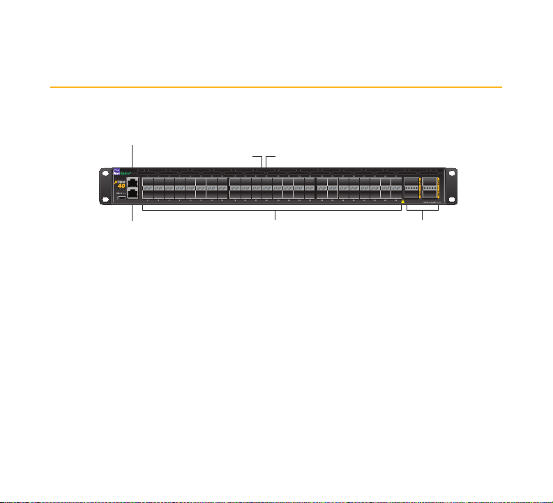
xStream 40 Appliance Overview
48 -10G
Network/Monitor Ports
Activity LEDLink LED
Console Port
Management
Port
4 - 40G
Network/Monitor Ports
Management
Console
• Console Port (RJ45)
• Management Port (RJ45)
• 48 x 10G Network/Monitor Ports (uses SFP, SFP+ transceivers)
• 4 x 40G Network/Monitor Ports (uses QSFP transceivers)
• 2 Hot swappable power units, AC or DC
• 5 Hot swappable fans
5
Page 6

Step 1
Rack Mount xStream 40
The xStream 40 device is designed to mount in a 19-inch rack, occupying 1U of
height. Do the following to install the xStream 40 into a 19-inch equipment rack:
1. Remove the screws from the shipping bag.
2. Slide the chassis into the rack and fasten it in place at the front panel ears using
the supplied screws and washers.
Grounding
Ground the chassis to the rack by connecting a 14 AWG minimum ground wire with a
#8 ring lug to the ground connection on the rear of the chassis. Terminate the other
end of the ground wire to the rack ground bus bar.
6
Page 7

7
Page 8

Step 2
Connect AC Power
Caution: Always connect the earth electrical grounds rst, and keep the earth grounds
connected whenever you are working on the device.
If possible, turn off the power to the power sources while you are making the power
connections.
If you are installing the device with AC connectors:
1. Plug one of the AC power cords to one of the AC power connectors on the rear
panel.
2. Plug the other end of the cord into an AC power circuit.
3. For redundant power, connect the other AC power cord to the other AC power
connector on the rear panel and plug the other end of the cord into a different
AC power source.
8
Page 9

Earth
Ground
Redundant Power
9
Page 10

Step 2 (cont.)
Connect DC Power
For DC powered models, you must supply your own power cables and one Phillips
screwdriver. DC power cables must have a wire gauge of at least 16 AWG and a 72
VDC, 6A rating. Remove the protective covers from the DC power terminal blocks. Use
the Phillips screwdriver to tighten the connections.
1. Connect a ground wire from the chassis ground to the rack.
2. Connect one end of another ground wire at the ground connector at Power 1
on the device chassis. Then connect the other end of the ground wire to the
ground connection at the DC power source.
3. Connect the negative (– 48VDC) side of a DC power cable to the Power 1
terminal on the chassis, labeled with the minus symbol (–), and connect the
positive (0V) side of the DC power cable to the Power 1 terminal labeled with
the plus symbol (+). The negative (minus symbol) terminal is in the center, and
the plus terminal is to the right.
4. Connect the other ends of the negative side and the positive sides of the DC
cable to the negative and positive connectors of the power source.
5. If you want to connect to redundant power, repeat steps 3 and 4 for Power 2
and then connect the other ends to a separate power source.
Note: Be sure to connect the positive sides of the cables to the positive sides of the
power sources, and the negative sides of the power cables to the negative sides of the
power sources. The two power LEDs on the front panel light up to indicate that both
power sources are on.
10
Page 11

Return
Ground
-48VDC
Chassis
Ground
Return
Ground
-48VDC
11
Page 12

Step 3
Log into the xStream 40
The xStream 40 is shipped with a default Management port IP address. If you
prepare your network to accept the default address, you can connect the device to
your network and log in using the default address.
IP: 10.60.4.180 Gateway: 10.0.0.1 Netmask: 255.0.0.0
If you want to assign the device a new IP address, you can connect a terminal to the
xStream 40 console port, log in, and assign a different IP address.
1. Connect a PC running terminal emulation software to the xStream 40 Console
port with the supplied DB9 to RJ45 console cable.
2. Launch the terminal emulation software, such as HyperTerminal or minicom,
and set the communication parameters to 115200 baud, 8 data bits, no parity,
1 stop bit, and no ow control.
3. At the login prompt, type admin, and at the password prompt, type netoptics.
4. At the CLI prompt, type cong to go into conguration mode.
5. Change the password for the admin account by entering the following CLI
commands:
passwd set password <new-pw>
reenterPassword <new-pw>
commit
where <new_pw> is the password you want to use.
12
Page 13
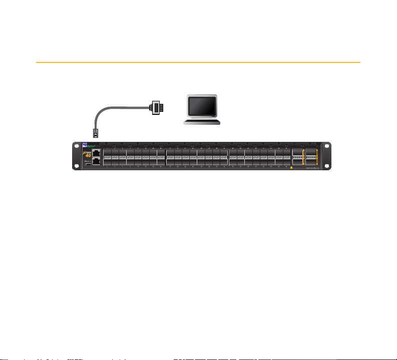
Management
Console
Computer with terminal
emulation software
DB9 to RJ45 console
cable
13
Page 14

Step 4
Congure the xStream 40 IP
To assign a new IP address using the CLI:
1. After the command prompt, type in the following command to set the new IP
address:
device sysIp ipSet address <ipaddress> netMask <netmask>
gateway <gateway>
where <ip address> is the IP address you want to set for the Management port,
<netmask> is the netmask, and <gateway> is the IP address of the gateway.
2. Conrm with a ‘yes’. The xStream 40 device takes on the new address
immediately.
To view the list of CLI commands, type ‘?’ at the prompt or type help. You can use the
tab key to auto-complete partially typed commands. Enter a command, space and
‘?’ to display the arguments for that command. For command details, see the CLI
Reference manual.
After the initial set up of the IP address through the local CLI, connect the
Management port with a CAT 5e cable to a switch or hub. You can access the xStream
40 CLI remotely by SSH or access the web interface through a web browser.
14
Page 15

Step 5
Check the xStream 40 Installation
After you have connected the xStream 40 device, verify that it is functioning correctly
by checking the link LEDs for each of the connected ports. The link LEDs should be
illuminated to indicate that the links are connected and trafc is present.
For more information, see the xStream 40 User Guide and the xStream 40 CLI
Command Reference on the CD that is included with the product.
15
Page 16

www.netoptics.com
If you have questions while your product is under warranty or you are enrolled
in a support plan, please contact the Net Optics Technical Assurance Center
(TAC) via email at support@netoptics.com or by calling +1.408.737.7777,
Monday through Friday, between the following hours in your region:
• 7:00 - 17:30 Americas (Pacic Time)
• 9:00 - 17:00 EMEA (Frankfurt Time)
• 9:00 - 17:00 APAC (Hong Kong Time)
You can also nd more information on our website at www.netoptics.com.
16
 Loading...