

Page 1
Installation Guide for
Optical Bypass Switch with Heartbeat
TM
800-0148-001 Doc. PUBBPOHBSXU Rev A, 06/06
Page 2

Page 3

Contents
Introduction . . . . . . . . . . . . . . . . . . . . . . . . . . . . . . . . . . . . . . . . . . . . . . . . . . . . . 1
Key Features . . . . . . . . . . . . . . . . . . . . . . . . . . . . . . . . . . . . . . . . . . . . . . . . . . . . 2
About this Guide . . . . . . . . . . . . . . . . . . . . . . . . . . . . . . . . . . . . . . . . . . . . . . . . . 2
Product Diagrams . . . . . . . . . . . . . . . . . . . . . . . . . . . . . . . . . . . . . . . . . . . . . . . . 3
Bypass Modes . . . . . . . . . . . . . . . . . . . . . . . . . . . . . . . . . . . . . . . . . . . . . . . . . . . 4
Power Loss Bypass . . . . . . . . . . . . . . . . . . . . . . . . . . . . . . . . . . . . . . . . . . . . . . . 5
Heartbeat Bypass . . . . . . . . . . . . . . . . . . . . . . . . . . . . . . . . . . . . . . . . . . . . . . . . 5
Optical Bypass Switch with Heartbeat
Unpacking and Inspection . . . . . . . . . . . . . . . . . . . . . . . . . . . . . . . . . . . . . . . . . . 7
Conguring the Bypass Switch . . . . . . . . . . . . . . . . . . . . . . . . . . . . . . . . . . . . . . 7
Connecting to the Network . . . . . . . . . . . . . . . . . . . . . . . . . . . . . . . . . . . . . . . . 11
Connecting to the In-line Device . . . . . . . . . . . . . . . . . . . . . . . . . . . . . . . . . . . 13
Specications . . . . . . . . . . . . . . . . . . . . . . . . . . . . . . . . . . . . . . . . . . . . . . . . . . 14
Limitations on Warranty and Liability . . . . . . . . . . . . . . . . . . . . . . . . . . . . . . . 15
Page 4

Optical Bypass Switch with Heartbeat
PLEASE READ THESE LEGAL NOTICES CAREFULLY.
By using a Net Optics Optical Bypass Switch you agree to the terms and conditions of usage set forth
by Net Optics, Inc.
No licenses, express or implied, are granted with respect to any of the technology described in this
manual. Net Optics retains all intellectual property rights associated with the technology described in
this manual. This manual is intended to assist with installing Net Optics products into your network.
Trademarks and Copyrights
© 2010 by Net Optics, Inc. Net Optics® is a registered trademark of Net Optics, Inc. Additional
company and product names may be trademarks or registered trademarks of the individual companies
and are respectfully acknowledged.
Additional Information
Net Optics, Inc. reserves the right to make changes in specications and other information contained
in this document without prior notice. Every effort has been made to ensure that the information in
this document is accurate.
Page 5

Introduction
Thank you for choosing the most versatile Optical Bypass Switch available
today. Whether you are a novice or an expert, this installation guide is
designed to help answer any questions and to provide a quick set-up reference.
Net Optics Optical Bypass Switches with Heartbeat provide a permanent and
trouble-free access port for in-line network security and monitoring devices.
The Optical Bypass Switch automatically switches network trafc through
added in-line devices or bypasses devices that are about to be removed. With
a heartbeat, the Optical Bypass Switch protects network trafc against both
signal and power loss on the attached in-line device.
Link Fault Protection
The Optical Bypass Switch with Heartbeat monitors the attached in-line device by sending a heartbeat packet to the device. If the Optical Bypass Switch
does not receive the heartbeat back, it automatically switches network trafc
to bypass the unresponsive device—even if the device is still receiving power.
The Optical Bypass continues to send the heartbeat and restores the trafc
through the in-line device as soon as the link is restored.
Uninterrupted Trafc
The Optical Bypass Switch supports fail-open monitoring with any GigaBit
in-line device when it shares the same power source as the in-line appliance.
For as long as the Optical Bypass Switch is receiving power, it diverts network trafc to attached in-line devices. In this state, all in-line trafc is routed
directly to the device connected to the Optical Bypass Switch.
Optical Bypass Switch with Heartbeat
When the Optical Bypass Switch loses power, in-line trafc continues to
ow through the network link, but is no longer routed through the device.
This allows the network devices to be removed and replaced without network
downtime. Once power is restored to the Optical Bypass Switch, network trafc is seamlessly diverted to the in-line device, allowing it to resume its critical
functions.
Simply Plug It In
Each Bypass Switch includes all the cables and power supplies you need
to quickly connect to an IPS. Three quick steps is all it takes to establish a
secure connection point for inline devices. For special applications, customize
the bypass trigger and Heartbeat rate from an RS232 command line interface.
1
Page 6

Key Features
Passive, Secure Technology
• Fail-open monitoring with any GigaBit ber in-line appliance at speeds of
1000 Mbps
• Protects against power, link, and application failure
• Increased reliability on critical network links
• High-speed optical switching with minimal insertion loss
• Congurable timeout (heartbeat) and retry
• Custom Heartbeat packet option
• Fully RoHS Compliant
Ease of Use
• LED indicators show power, speed, link, and activity status
• Front-mounted connectors support easy installation and operation
• Silk-screened application diagram illustrates all connections for easy
deployment
• Optional 19-inch rack frames holds two Bypass Switches
• Tested and compatible with all major manufacturers’ monitoring devices,
including protocol analyzers, probes, and intrusion detection/prevention
systems
Support
• Net Optics offers free technical support throughout the lifetime of your
purchase. Our technical support team is available from 8 am to 5 pm Pacic
Time, Monday through Friday at +1 (408) 737-7777 and via email at
ts-support@netoptics.com. FAQs are also available on Net Optics website
at www.netoptics.com
Optical Bypass Switch with Heartbeat
About this Guide
This guide covers the installation and use of the following models:
Part Number Description
BPO-HBSX-LC GigaBit SX Bypass Switch with Heartbeat
BPO-HBSX-SC/LC GigaBit SX Bypass Switch with Heartbeat, SC to LC
BPO-HB-LX/SX GigaBit LX to SX Bypass Switch with Heartbeat
BPO-HBLX-SC/LC GigaBit LX Bypass Swith with Heartbeat, SC to LC
BPO-HBLX-LC GigaBit SX Bypass Switch with Heartbeat
BPO-HB50SX-LC GigaBit SX Bypass Switch with Heartbeat, 50µm
cables
cables
2
Page 7

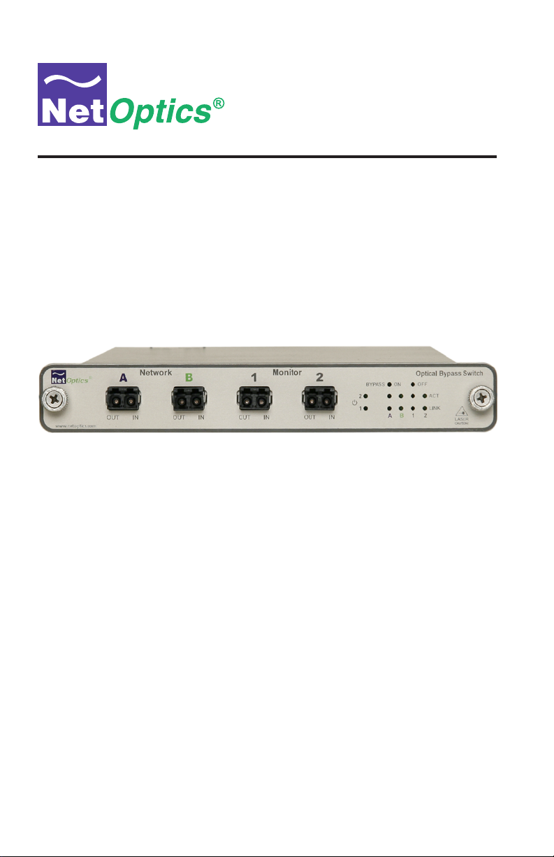
Product Diagrams
®
www.netoptics.com
Figure 1: Front View Panel
Network Monitor
A B 1 2
OUT IN OUT IN OUT IN OUT IN
Network Ports
A & B
Optical Bypass Switch with Heartbeat
Bypass Indicator
LEDs
Optical Bypass Switch
B 1 2A
Activity & Link
LEDs
ACT
LINK
Monitor Ports
C & D
BYPASS ON OFF
2
1
Power
LEDs
LASER
CAUTION!
Figure 2: Rear View Panel
RS232 Port PWR DC Jack Terminals
Figure 3: Application Diagram
Silk Screen Diagram
Tx Rx Tx Rx Tx Rx Tx Rx
®
A
B
C D
Monitor
Port D
Network
Port A
96590
Network
Port B
Network
Monitor
Port C
1 2
+
OUTPUT PIN ASSIGNMENT
12 Volt 3.0 Amp
Optical Bypass Switch
B
Optical Bypass Switch
BYP ASS
OFF ON
2
M o n i t o r
OUT IN OUT IN OUT IN OUT IN
ACT
1
LINK
D C B A
®
LASER
CAUTION!
3
Page 8

Bypass Modes
The Optical Bypass Switch with Heartbeat bypasses attached in-line device
when one of three events occurs:
• Power loss to the switch
• Link failure
• Application failure
Two LEDs on the front of the Optical Bypass Switch indicate whether the
switch is bypassing the connected appliance or not. When the Bypass ON
indicator is illuminated, the bypass switch has not received the heartbeat
packet as expected and is in Bypass Enabled mode. When the Bypass OFF
indicator is illuminated, the bypass switch is in Bypass Disabled mode and is
sending trafc through the attached in-line device.
When the switch is in Bypass Enabled (ON) mode, the switch circuitry
re-directs network trafc around the in-line appliance. In Bypass Enabled
mode Network Ports A and B are connected (see Figure 4).
Tx Rx Tx Rx Tx Rx Tx Rx
®
www.netoptics.com
Figure 4: Bypass Enabled
When the switch is in Bypass Disabled (OFF) mode, the switch circuitry
sends network trafc through the in-line appliance. In Bypass Disabled mode,
Network Port A is connected to Monitor Port C and Network Port B is con-
nected to Monitor Port D (see Figure 5).
Optical Bypass Switch with Heartbeat
Network Monitor
A B 1 2
OUT IN OUT IN OUT IN OUT IN
BYPASS ON OFF
2
1
Optical Bypass Switch
ACT
LINK
B 1 2A
LASER
CAUTION!
Tx Rx Tx Rx Tx Rx Tx Rx
Network Monitor
®
A B 1 2
OUT IN OUT IN OUT IN OUT IN
www.netoptics.com
Figure 5: Bypass Disabled
Optical Bypass Switch
BYPASS ON OFF
2
1
ACT
LINK
B 1 2A
LASER
CAUTION!
4
Page 9

Power Loss Bypass
The Optical Bypass Switch protects link integrity when the attached in-line
device loses power. To install the Optical Bypass Switch for this type of
protection, the switch should share the same power source as the in-line
appliance. If you are using redundant power supplies for the switch, make
sure that both are connected to the same power source as the in-line device.
Heartbeat Bypass
The Optical Bypass Switch with Heartbeat protects against both physical link
failure and application failure on the in-line appliance. The switch checks
the path through the in-line appliance by sending a packet every second from
Monitor Port C. The switch validates the path when it receives the packet
on the Monitor Port D. If the switch does not receive the packet as expected
three times in a row, the switch automatically enters Bypass Enabled (ON)
mode.You can change the number of the heartbeat packets required before the
bypass switch enters Bypass Enabled mode from the bypass switch CLI (see
Conguring the Bypass Switch on page 6).
Below is the default IPX heartbeat packet sent once every second from the
Monitor Port C. You can change the default timing of the heartbeat packet
and the heartbeat packet from the bypass switch CLI (see Conguring the
Bypass Switch on page 6).
Optical Bypass Switch with Heartbeat
The switch continues to send the bypass packet and will return to Bypass
Disabled mode when it receives three consecutive packets on Monitor Port D.
The default IPX and IP packets are shown on the following page. Units are
shipped from the factory with the IPX packet. When the factory defaults are
restored using the "z" CLI command (see "To restore the bypass switch to
factory defaults" on page 11), you will be able to select either the IPX or IP
packet.
5
Page 10

Optical Bypass Switch with Heartbeat
IPX Packet
Packet Contents (Hex) Description
----------------------------- ----------------
00 50 C2 3C 60 00 MAC DA Net Optics
00 50 C2 3C 60 01 MAC SA Net Optics
81 37 Packet Type IPX
FF FF 00 30 00 00 00 00
40 04 EC A2 C6 13 01 02
C6 13 01 01 00 00 00 00
00 00 00 00 00 00 00 00
00 00 00 00 00 00 00 00
00 00 00 00 00 00 00 00
82 A2 BA 71 CRC
IP Packet
Packet Contents (Hex) Description
----------------------------- ----------------
00 50 C2 3C 60 00 MAC DA Net Optics
00 50 C2 3C 60 01 MAC SA Net Optics
08 00 Packet Type IP
45 00 00 3C 18 D2 00 00
80 01 0A FF 0A 02 01 DC
0A 01 01 12 08 00 37 5C
02 00 14 00 61 62 63 64
65 66 67 68 69 6A 6B 6C
6D 6E 6F 70 71 72 73 74
75 76 77 61 62 63 64 65
66 67 68 69
B8 8E 1C A9 CRC
6
Page 11

Unpacking and Inspection
Unpack the Optical Bypass Switch, power supplies, and cables provided.
Each Optical Bypass Switch is delivered with the following:
• 2 Power supplies
• 2 LC ber cables (models
HBLX-SC/LC) or 2 LC-to-SC cables (model BPO-HBSX-SC/LC)
BPO-HBSX-LC0, BPO-HB-LX/SX, and BPO-
• 1 DB-9 RS232 cable
• 1 Manual
You may have also purchased a panel for rack mounting the bypass switch and
an extended warranty. If any component is missing or damaged, contact Net
Optics Customer Service immediately.
Conguring the Bypass Switch
The Optical Bypass Switch allows you to set several conguration options and
to display conguration information. You can set:
The frequency of the heartbeat.
This denes the period of time that passes before the switch
considers the packet to have timed out. The default is 1 second.
Optical Bypass Switch with Heartbeat
The number of timeouts allowed.
This is the number of packets missed before the switch bypasses
the IPS (retry count). The default is 3 missed packets.
Port communication parameters.
You can turn Link Fault Detect and Bypass Detect on or off.
The default is LFD and Bypass Detect on.
A custom heartbeat packet.
You can input a custom heartbeat packet to suit special needs. The
default is the IPX packet shown on page 5.
Reset to factory defaults.
Use this option to quickly restore the original conguration.
For quick reference, you can display the conguration settings and heartbeat
packet.
7
Page 12

Optical Bypass Switch with Heartbeat
Link Fault Detect
You can set the bypass switch to drop the remaining full-duplex link when one
side fails. The Link Fault Detect features ensures that connected devices are
aware of a failure on both sides of the link.
Bypass Detect
You can set the Monitor Ports to cycle on and off while the bypass switch is
in Bypass Enabled mode. In Bypass Detect mode, the Monitor Ports cycle
through ve seconds off followed by fteen seconds on. The alternating link
status can be used to trigger attached devices to send an alarm to a manage-
ment system every time the bypass switch turns off the Monitor Ports. When
the bypass switch returns to Bypass Disabled mode, the Monitor Ports remain
on and the on/off cycle is discontinued.
Note: ________________________________________________________________
Before starting, make sure power to the bypass switch is disconnected.
______________________________________________________________________
To access the bypass switch CLI:
1. Using the RS232 DB-9 cable provided, connect a PC running terminal
emulation software, such as HyperTerminal to the RS232 port on the rear
panel of the bypass switch.
2. Set the terminal emulation software to the following communication
parameters:
9600 baud
8 data bit
No parity
1 stop bit
No ow control
3. Connect power to the bypass switch. The software compile date and time
is displayed in the terminal emulation software as shown in the example
below.
Compiled on 16-Jan-06 15:35:00
Type ? for a list of commands
4. Type ? and press ENTER for a list of commands.
8
Page 13

Optical Bypass Switch with Heartbeat
The following commands are listed:
a = Input Timeouts
b = Input Conguration
c = Input Heartbeat Packet
d = Display Conguration
e = Display Heartbeat Packet
z = Reset to Factory Defaults
To set the timeout values:
1. Type a and press Enter to set the timeout values.
2. At the input time out period prompt, enter the number of
seconds between each heartbeat (1-254 seconds). Press Enter.
3. At the input retry count prompt, enter the number of missed
heartbeats allowed before the switch enters Bypass ON mode (1-254).
The input retry count must be greater than or equal to the input timeout.
Press Enter.
Note: ________________________________________________________________
Manufacturing default for Input Timeout Period and Input Retry Count are set
to 1 and 3 respectively.
______________________________________________________________________
To set the LFD and Bypass Detect options:
1. Type b and press Enter.
2. At the Bypass Detect on/o prompt, type 1 to turn on or 0 to turn
off Bypass Detect.
3. At the LFD on/o prompt, type 1 to turn on or 0 to turn off Link Fault
Detect.
To input a custom heartbeat packet:
1. Type c and press Enter. You are prompted for the length of the packet
including header bytes and CRC bytes.
2. Enter the length of your custom packet in decimal format and press Enter.
You are prompted for each packet byte.
9
Page 14

Optical Bypass Switch with Heartbeat
3. Enter packet bytes in Hex format in the following order:
MAC DA Net Optics (6 bytes)
MAC SA Net Optics (6 bytes)
Packet Type (2 bytes)
Packet Bytes
CRC (4 bytes)
Alternately you can load the packet as a pre-formatted text le. The text
le should be one byte per line, beginning with a decimal value for the
number of packets followed by hex values for the remaining bytes. Load
the text le at the packet length prompt.
To load a custom packet from byte-by-byte or from a le, you must set the
Line Delay to 1000 milliseconds and the Character Delay to 100 millisec-
onds in your terminal emulation software. If you are using HyperTerminal,
these settings are located in the ASCII Setup dialog box found in File>Prop
erties>Settings>ASCII Setup.
To display the current values:
1. Type d and press Enter. A list similar to the following appears.
input timeout period 1
input retry count 3
LFD on
Bypass Detect on
Bypass Disabled
To display the current packet:
1. Type e and press Enter. The packet is displayed as shown in the example
below.
packet length = 78
MAC DA 00 50 c2 3c 60 00
MAC SA 00 50 c2 3c 60 01
Packet Type 08 00
45 00 00 3c 18 d2 00 00
80 01 0a 0a 02 01 dc
0a 01 01 12 08 00 37 5c
02 00 14 00 61 62 63 64
65 66 67 68 69 6a 6b 6c
6d 6e 6f 70 71 72 73 74
75 76 77 61 62 63 64 65
66 67 68 69
CRC bb 8e 1c a9
10
Page 15

To restore the bypass switch to factory defaults:
1. Type z and press Enter. You are prompted to select which type of packet
you want to restore, IP or IPX.
2. Select 1 to restore defaults with an IP packet or 0 to restore defaults with
an IPX packet.
The bypass switch will be reset to the following defaults:
Input Timeout Period: 1
Input Retry Count: 3
LFD: On
Bypass Detect: On
Heartbeat Packet: IPX
Connecting to the Network
To connect the bypass switch to the network:
1. Connect Network Port A to the appropriate switch, server or router device.
This acts as your DCE interface.
Optical Bypass Switch with Heartbeat
2. Connect Network Port B to the appropriate switch, server or router device.
This acts as your DTE interface.
11
Page 16

Optical Bypass Switch with Heartbeat
Network Monitor
®
A B 1 2
OUT IN OUT IN OUT IN OUT IN
www.netoptics.com
Rx
B
Figure 6: Connecting to the Network
3. Verify that the bypass switch Network Ports are cabled in-line between two
devices.
Tx
A
To Switch, Server, or Router
To Switch, Server, or Router
BYPASS ON OFF
2
1
Optical Bypass Switch
ACT
LINK
B 1 2A
LASER
CAUTION!
Note ________________________________________________________________
Model BPO-HB-LX/SX has a built-in LX-to-SX media converter. Connect your
LX network devices to the Network Ports and your SX in-line device to the
Monitor Ports.
______________________________________________________________________
12
Page 17

Connecting to the In-line Device
To connect the bypass switch to the in-line device:
1. Connect Monitoring Port C to the in-line appliance using a duplex LC ber
cable. This acts as your DCE interface.
2. Connect Monitoring Port D to the in-line appliance using a duplex LC ber
cable. This acts as your DTE interface.
Network Monitor
®
A B 1 2
OUT IN OUT IN OUT IN OUT IN
www.netoptics.com
Optical Bypass Switch with Heartbeat
Optical Bypass Switch
BYPASS ON OFF
2
1
ACT
LINK
B 1 2A
LASER
CAUTION!
Figure 7: Connecting to the In-Line Device
3. Verify that the bypass switch Monitoring Ports are cabled in-line to the
attached device.
4. Connect power to the switch. If you are implementing power fault failover,
make sure you connect the switches' power supplies to the same power
sources that the IPS is using.
Rx
B
Tx
A
To monitoring device
To monitoring device
13
Page 18

Optical Bypass Switch with Heartbeat
Specications
Splitter Specications
Fiber Type: Multimode: Corning 50 or 62.5/125µm, wavelength, 850nm
Insertion Loss: Network Port: ≤ 1.25 dB
Monitor Port: ≤ 1.25 dB
Fiber Type: Singlemode: Corning 8.5/125µm, wavelength, 1310nm
Insertion Loss: Network Port: ≤ 1.25 dB
Monitor Port: ≤ 1.25 dB
Note: ________________________________________________________________
There is no insertion loss when the bypass switch is not receiving power.
______________________________________________________________________
Environmental
Operating Temperature: 0˚C to 40˚C
Storage Temperature: -10˚C to 70˚C
Relative Humidity: 10% min, 95% max, non-condensing
Power
Power Supply: Input Power: 100-240V, 0.5A, 47-63Hz
Output Power: 12V, 1.5A
Mechanical
Dimensions: 1.125” high x 11.5” deep x 6.5” wide
Connectors
(2) Duplex LC connectors (monitoring ports)
(2) Duplex LC connectors (network ports)
Cables
BPO-HBSX-LC model: (2) LC cables, 3 meter
BPO-HB-LX/SX model: (2) LC cables, 3 meter
Certications
Fully RoHS Compliant
14
Page 19

Optical Bypass Switch with Heartbeat
Limitations on Warranty and Liability
Net Optics offers a limited warranty for all its products. IN NO EVENT SHALL NET OPTICS, INC.
BE LIABLE FOR ANY DAMAGES INCURRED BY THE USE OF THE PRODUCTS (INCLUDING BOTH HARDWARE AND SOFTWARE) DESCRIBED IN THIS MANUAL, OR BY ANY
DEFECT OR INACCURACY IN THIS MANUAL ITSELF. THIS INCLUDES BUT IS NOT LIMITED TO LOST PROFITS, LOST SAVINGS, AND ANY INCIDENTAL OR CONSEQUENTIAL
DAMAGES ARISING FROM THE USE OR INABILITY TO USE THIS PRODUCT, even if Net
Optics has been advised of the possibility of such damages. Some states do not allow the exclusion
or limitation of implied warranties or liability for incidental or consequential damages, so the above
limitation or exclusion may not apply to you.
Net Optics, Inc. warrants this Optical Bypass Switch to be in good working order for a period of ONE
YEAR from the date of purchase from Net Optics or an authorized Net Optics reseller.
Should the unit fail anytime during the said ONE YEAR period, Net Optics will, at its discretion,
repair or replace the product. This warranty is limited to defects in workmanship and materials and
does not cover damage from accident, disaster, misuse, abuse or unauthorized modications.
If you have a problem and require service, please call the number listed at the end of this section and
speak with our technical service personnel. They may provide you with an RMA number, which must
accompany any returned product. Return the product in its original shipping container (or equivalent)
insured and with proof of purchase.
Additional Information
Net Optics, Inc. reserves the right to make changes in specications and other information contained
in this document without prior notice. Every effort has been made to ensure that the information in
this document is accurate. Net Optics is not responsible for typographical errors.
THE WARRANTY AND REMEDIES SET FORTH ABOVE ARE EXCLUSIVE AND IN LIEU OF
ALL OTHERS, EXPRESS OR IMPLIED. No Net Optics reseller, agent, or employee is authorized
to make any modication, extension, or addition to this warranty.
Net Optics is always open to any comments or suggestions you may have about its products and/or
this manual.
Send correspondence to
Net Optics, Inc.
5303 Betsy Ross Drive
Santa Clara, CA 95054 USA
Telephone: +1 (408) 737-7777
Fax: +1 (408) 745-7719
Email: info@netoptics.com/Internet: www.netoptics.com
All Rights Reserved. Printed in the U.S.A. No part of this publication may be reproduced, transmit-
ted, transcribed, stored in a retrieval system, or translated into any language or computer language,
in any form, by any means, without prior written consent of Net Optics, Inc., with the following
exceptions: Any person is authorized to store documentation on a single computer for personal use
only and that the documentation contains Net Optics’ copyright notice.
15
Page 20

www.netoptics.com
© 2010 by Net Optics, Inc. All Rights Reserved.
 Loading...