

Page 1
Installation Guide for
Link Aggregator Tap
10/100 In-Line to GigaBit
with SFP Monitor Ports
Doc. PUBLAIF4CU4SFPU Rev. 1, 10/08
Page 2

Page 3

Contents
Introduction .....................................................1
Key Features ....................................................2
Application Diagram ..............................................3
Cabling Guidelines . . . . . . . . . . . . . . . . . . . . . . . . . . . . . . . . . . . . . . . . . . . . . . . 3
Product Diagrams . . . . . . . . . . . . . . . . . . . . . . . . . . . . . . . . . . . . . . . . . . . . . . . . 4
LED Indicators . . . . . . . . . . . . . . . . . . . . . . . . . . . . . . . . . . . . . . . . . . . . . . . . . . 5
Connecting to the Network .........................................5
10/100 In-Line Link Aggregator Tap
Connecting to the Monitoring Device .................................6
Dip Switch Settings. . . . . . . . . . . . . . . . . . . . . . . . . . . . . . . . . . . . . . . . . . . . . . . 7
Specications . . . . . . . . . . . . . . . . . . . . . . . . . . . . . . . . . . . . . . . . . . . . . . . . . . . 8
Limitations on Warranty and Liability . . . . . . . . . . . . . . . . . . . . . . . . . . . . . . . . 9
Page 4

10/100 In-Line Link Aggregator Tap
PLEASE READ THESE LEGAL NOTICES CAREFULLY.
By using a Net Optics Tap you agree to the terms and conditions of usage set forth by Net Optics, Inc.
No licenses, express or implied, are granted with respect to any of the technology described in this
manual. Net Optics retains all intellectual property rights associated with the technology described in
this manual. This manual is intended to assist with installing Net Optics products into your network.
Trademarks and Copyrights
© 2007 by Net Optics, Inc. Net Optics® is a registered trademark of Net Optics, Inc. Additional company and product names may be trademarks or registered trademarks of the individual companies and
are respectfully acknowledged.
Additional Information
Net Optics, Inc. reserves the right to make changes in specications and other information contained
in this document without prior notice. Every effort has been made to ensure that the information in this
document is accurate.
Page 5

Introduction
Thank you for choosing the most versatile monitoring Tap available today.
Net Optics Link Aggregator Taps are an efciency breakthrough for passively
monitoring multiple full-duplex links. Whether you are a novice or an expert,
this installation guide is designed to help answer any questions and to provide
a quick set-up reference.
Net Optics Link Aggregator Tap provides superior monitoring coverage while
leveraging monitoring resources. Providing trafc from multiple network
links, the Link Aggregator Tap combines up to four full-duplex 10/100BaseT
links (eight half-duplex data streams) into one, two or four GigaBit monitor
ports.
Installing a monitoring device in each segment of the network is often time
consuming and expensive. Restricted by tight budgets, security managers must
make compromises that leave portions of the network exposed to attacks.
Net Optics’ Link Aggregator addresses this challenge by increasing the number of links covered by monitoring devices already installed.
No Packets Left Behind
The Link Aggregator Tap buffers and scans incoming trafc from the network
ports on a round-robin basis. Buffer size and scan rate is optimized to ensure
that no packets are dropped and there is no bandwidth limitation on incoming
data streams. The buffers and the high bandwidth of GigaBit monitor ports
guarantee that no data is lost during trafc surges.
10/100 In-Line Link Aggregator Tap
Security and Visibility
Without an IP address, monitoring devices are isolated from the network,
dramatically reducing their exposure to attacks. However, the monitoring
device connected to the Tap still sees all full-duplex trafc as if it were in-line,
including Layer 1 and Layer 2 errors.
Reliability
For extra uptime protection, Net Optics Taps offer redundant power connections. Should the primary power source fail, the Tap automatically switches
to the backup power source. Power LEDs on the front of the Tap indicate the
current power source.
1
Page 6

Key Features
Passive, Secure Technology
Supports full-duplex monitoring of four links with a single NIC, increasing •
monitoring efciency
Optional Regeneration Tap technology enables up to four devices to simul-•
taneously monitor all aggregated trafc
Unique Zero Delay™ technology ensures no packet delay or loss if power •
is lost to the Tap
Provides complete full-duplex visibility at 10 or 100 Mbps without data •
stream interference or introducing a point of failure
Passes all trafc (including errors) from all layers for comprehensive •
troubleshooting
No IP address is needed for the Tap or monitoring device, enhancing •
monitoring security
Redundant power ensures monitoring uptime•
Fully RoHS compliant•
Fully IEEE 802.3 compliant•
Ease of Use
LED indicators show redundant power, speed, link, and activity status•
Front-mounted connectors support easy installation and operation•
Monitoring and network cables included for plug-and-play deployment•
Silk-screened application diagram illustrates all connections for easy •
deployment
Small form-factor pluggable (SFP) monitor port connectors increase •
monitoring options
Compatible with all major manufacturers’ monitoring devices, including •
protocol analyzers, probes, and intrusion detection/prevention systems
Support
Net Optics offers free technical support throughout the lifetime of your •
purchase. Our technical support team is available from 8 am to 5 pm
Pacic Time, Monday through Friday at +1 (408) 737-7777 and via email at
ts-support@netoptics.com. FAQs are also available on Net Optics website
at www.netoptics.com.
10/100 In-Line Link Aggregator Tap
2
Page 7
10/100 In-Line Link Aggregator Tap
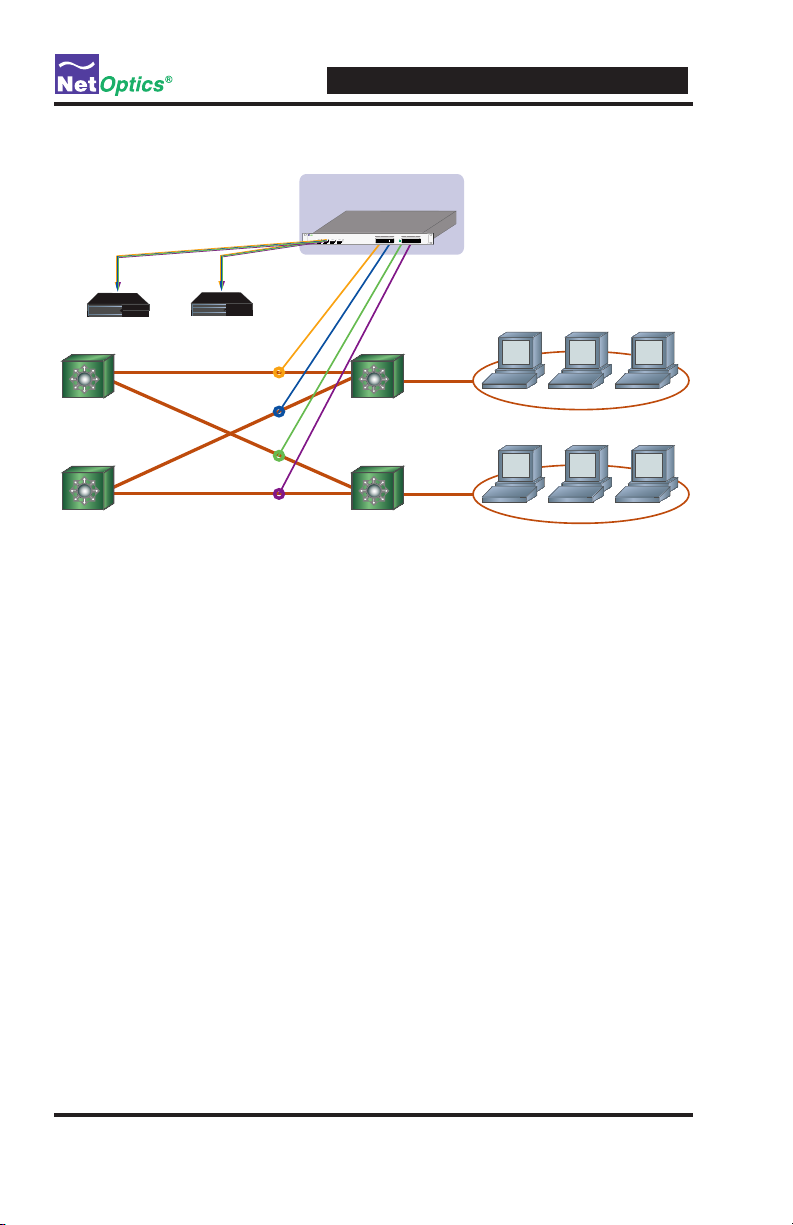
Link Aggregator Tap Implementation
Switch
Switch
Switch
HR
Finance
Switch
10/100 In-Line
Link Aggregator Tap
GigaBit SX
Monitoring
Device 2
GigaBit SX
Monitoring
Device 1
Application Diagram
Figure 1: Application Diagram
Zero DelayTM - A Net Optics Breakthrough
Highly sensitive network locations can improve monitoring performance via
the innovative features of Net Optics Taps. If power is lost to other 10/100
Taps, the connected devices may introduce delays as they detect the power
loss and try to re-establish their link. Net Optics’ pioneering design ensures
that any loss of power to the Tap is transparent to the network and does not
affect the ow of trafc through the Tap – eliminating packet delay and loss as
potential security issues.
Cabling Guidelines
If connecting to Switches or Hubs, use CAT5e RJ45 cross-over cabling•
If connecting to routers or NICs, use CAT5e RJ45 straight-through cabling•
3
Page 8

10/100 In-Line Link Aggregator Tap
®
www.netoptics.com
In-Line Link Aggregator
Monitor
Network
LINK
ACT
LINK
ACT
LINK
ACT
LINK
ACT
1 2 3 4
21
A BA B
43
A BA B
LINK
ACT
1
2
Monitor Ports
Network Ports
Link LEDs
Power LEDs
2
Power Rating: 90 to 264 VAC
1
Input: 47-63Hz
1
2
Power LEDs
Power Connectors
Unpacking and Inspection
Carefully unpack the 10/100 In-Line Link Aggregator Tap and check for damaged or missing parts. The Link Aggregator Tap ships with the following:
10/100 In-Line Link Aggregator Tap •
Two power cords•
Installation Guide•
In addition to the Port Aggregator, you should have ordered at least one SFP
module. You may have also ordered an extended warranty. Carefully check the
packing slip against parts received. If any part is missing or damaged, contact
Net Optics' Customer Service immediately.
Part Number Description
LA-IF4CU/4SFP In-line 10/100 to SFP Link Aggregator
LA-IF4CU/4SFP-48V In-line 10/100 to SFP Link Aggregator, -48V DC
Product Diagrams
Figure 2: Front Panel
Figure 3: Rear Panel
4
Page 9
LED Indicators
www.netoptics.com
In-Line Link Aggregator
Monitor
Network
LINK
ACT
LINK
ACT
LINK
ACT
LINK
ACT
1 2 3 4
21
A BA B
43
A BA B
LINK
ACT
1
2
To A switch, server or router
To B switch, server or router
PWR 1/ PWR 2• : Main and Redundant Power. If the Tap is deployed with
both power supplies, both LEDs illuminate when the Tap is plugged in. If
an LED is off, this indicates that the corresponding power supply is not
connected or not functioning.
Activity Indicator• : When there is activity on the link, LED ashes green.
Link Indicator• : When a good link is established, the LED is a solid green.
Connecting to the Network
To connect to the network:
1. Connect Network Port 1 to the appropriate switch, server or router device
using a CAT5e RJ45 cable.
2. Connect Network Port 2 to the appropriate switch, server or router device
using a CAT5e RJ45 cable.
10/100 In-Line Link Aggregator Tap
Figure 4: Connecting to the Network
3. Repeat Steps 1 and 2 for the rest of the network ports of the Link
Aggregator Tap.
4. Verify that the Link Aggregator Tap Network Ports are cabled in-line
between two devices.
Note: ______________________________________________________________
The second power supply is available to support the ow of trafc to the
monitoring device should the rst power supply fail. If the rst power supply
is unavailable, the second power supply supplies all power for the Tap.
____________________________________________________________________
5
Page 10

10/100 In-Line Link Aggregator Tap
®
www.netoptics.com
In-Line Link Aggregator
Monitor
Network
LINK
ACT
LINK
ACT
LINK
ACT
LINK
ACT
1 2 3 4
21
A BA B
43
A BA B
LINK
ACT
1
2
To Monitor Device
NOTE: _____________________________________________________________
At 10Mbps, if any of the network links are unplugged during operation, it
will be necessary to restart trafc from the connected network devices upon
re-connecting to the Link Aggregator. This is to ensure that trafc is properly
copied to the monitor ports and only applies to networks running at 10Mbps.
____________________________________________________________________
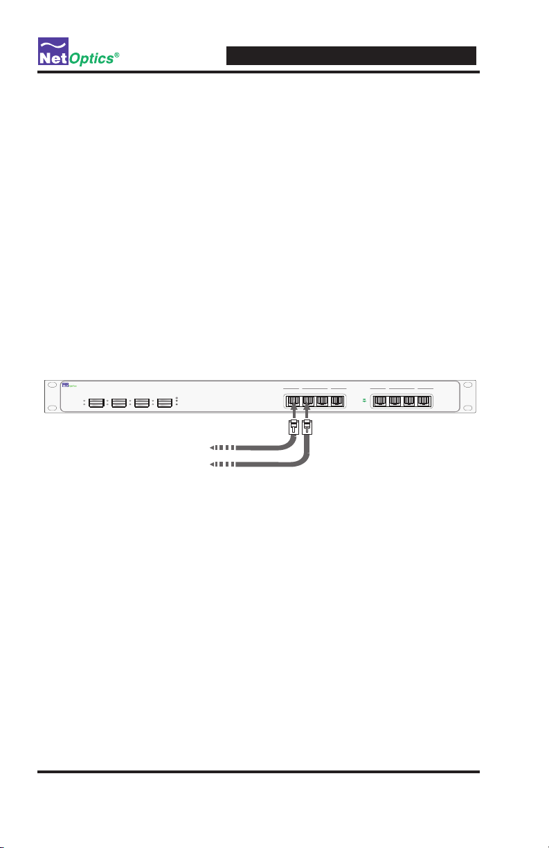
Connecting Monitoring Devices
1. Supply power to the Tap using the power supply adapter included
with the unit. Verify that the power LED illuminates.
2. Remove the SFP from its protective packaging.
3. Remove the temporary plug from Monitor Port 1.
Figure 5: Connecting to Monitoring Devices using SFP modular connectors
4. Insert the SFP in the Monitor 1 Port until you hear it click into place.
5. Connect Monitoring Port 1 to the appropriate port on the monitoring
device. This will monitor all aggregated links connected to the network
ports.
6. If you are installing multiple SFPs, repeat Steps 1 through 4 for Monitor
Port 2.
6
Page 11
10/100 In-Line Link Aggregator Tap
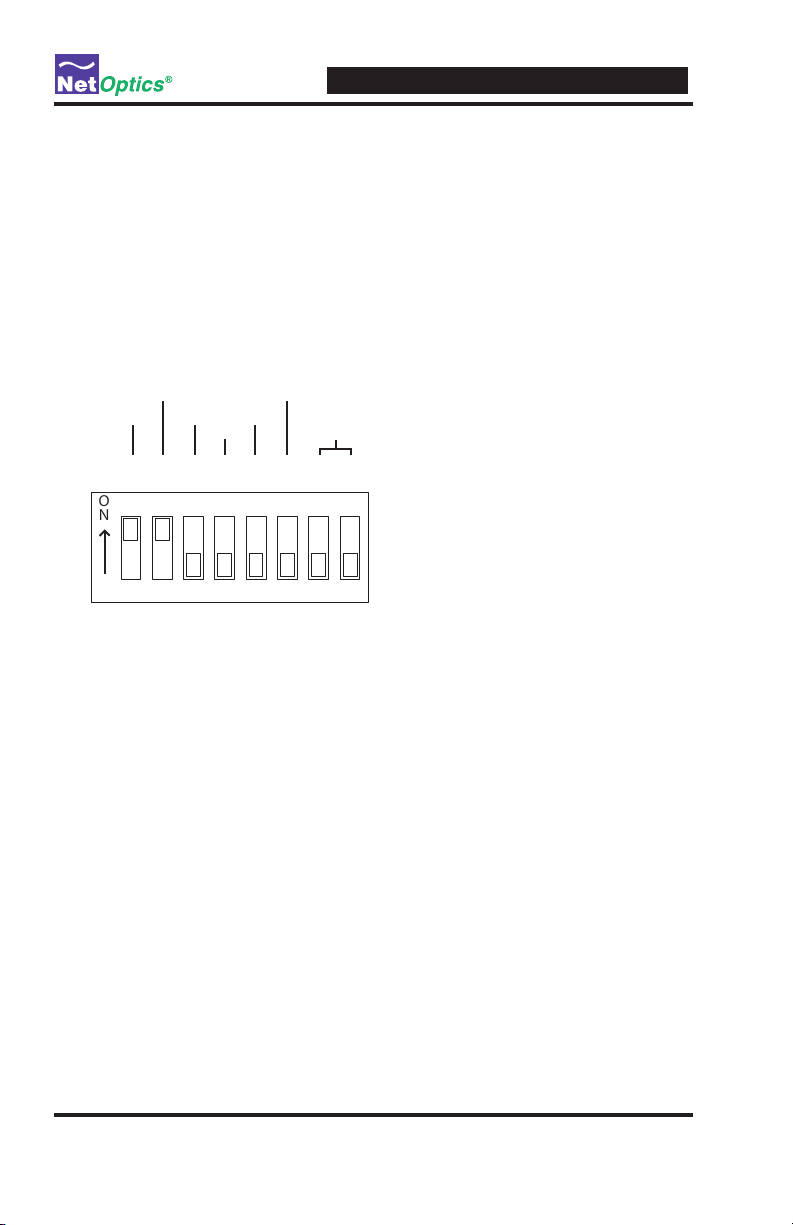
NOTE: To activate, push buttons UP.
(This diagram shows all segments
in the OFF position)
1 3 4 5 6 7 8 2
/.
LINK
FAULT
ON
OFF
ON
OFFONOFFONOFFFDHDONOFFONOFF
10
100
RESERVED
ON
OFF
RESERVED
DUPLEX
AUTO
NEGOTIATION
Note: ______________________________________________________________
The 10/100 Link Aggregator is shipped with the following default dip-switch
settings. It is strongly recommended that you do not make any changes to
these settings, except when needed, and only to switches 2,4,5 and 6. If Switch
3, for example, is toggled to "on," the Link Aggregator will not get a valid
link. In the event that the aforementioned occurs, it will be necessary to return
the dip-switches to the default states and to power-cycle the unit.
___________________________________________________________________
Figure 6: Default Dip-switch Settings
7
Page 12

Specications
Environment
Operating Temperature: 0˚C to 55˚C
Storage Temperature: -10˚C to 70˚C
Relative Humidity: 10% min, 95% max, non-condensing
Power
Power Supply Input: 100-240VAC, 0.5A, 47-63Hz
DC Power Input: -48 VDC typical, -36 VDC min, -75 VDC max
Mechanical
Dimensions: 1.75” high x 17.125” deep x 17” wide
Certications
Fully RoHS compliant
Copper Interface
Cable Type: 22-24 AWG unshielded twisted pair cable, CAT5/CAT5e
Link Distance Supported: 100 meters
Optical Interface
Fiber Type: Multimode: Corning 62.5/125µm, wavelength, 850nm
Fiber Type: Singlemode: Corning 8.5/125µm, wavelength, 1310nm
10/100 In-Line Link Aggregator Tap
Connectors
LA-IF4CU/4SFP and LA-IF4CU/4SFP-48V:
(8) RJ45, 8-pin connectors (network ports)
(4) SFP ports for SFP modular connectors
Accessories
SFP Conversion Kits
SFPKT-SX Multimode ber SFP with cable
SFPKT-LX Singlemode ber SFP with cable
SFPKT-CU GigaBit copper SFP with cable
8
Page 13

10/100 In-Line Link Aggregator Tap
Limitations on Warranty and Liability
Net Optics offers a limited warranty for all its products. IN NO EVENT SHALL NET OPTICS, INC.
BE LIABLE FOR ANY DAMAGES INCURRED BY THE USE OF THE PRODUCTS (INCLUDING BOTH HARDWARE AND SOFTWARE) DESCRIBED IN THIS MANUAL, OR BY ANY
DEFECT OR INACCURACY IN THIS MANUAL ITSELF. THIS INCLUDES BUT IS NOT LIMITED TO LOST PROFITS, LOST SAVINGS, AND ANY INCIDENTAL OR CONSEQUENTIAL
DAMAGES ARISING FROM THE USE OR INABILITY TO USE THIS PRODUCT, even if Net
Optics has been advised of the possibility of such damages. Some states do not allow the exclusion
or limitation of implied warranties or liability for incidental or consequential damages, so the above
limitation or exclusion may not apply to you.
Net Optics, Inc. warrants this Tap to be in good working order for a period of ONE YEAR from the
date of purchase from Net Optics or an authorized Net Optics reseller.
Should the unit fail anytime during the said ONE YEAR period, Net Optics will, at its discretion,
repair or replace the product. This warranty is limited to defects in workmanship and materials and
does not cover damage from accident, disaster, misuse, abuse or unauthorized modications.
If you have a problem and require service, please call the number listed at the end of this section and
speak with our technical service personnel. They may provide you with an RMA number, which must
accompany any returned product. Return the product in its original shipping container (or equivalent)
insured and with proof of purchase.
Additional Information
Net Optics, Inc. reserves the right to make changes in specications and other information contained
in this document without prior notice. Every effort has been made to ensure that the information in
this document is accurate. Net Optics is not responsible for typographical errors.
THE WARRANTY AND REMEDIES SET FORTH ABOVE ARE EXCLUSIVE AND IN LIEU OF
ALL OTHERS, EXPRESS OR IMPLIED. No Net Optics reseller, agent, or employee is authorized
to make any modication, extension, or addition to this warranty.
Net Optics is always open to any comments or suggestions you may have about its products and/or
this manual.
Send correspondence to
Net Optics, Inc.
5303 Betsy Ross Drive
Santa Clara, CA 95054 USA
Telephone: +1 (408) 737-7777
Fax: +1 (408) 745-7719
Email: info@netoptics.com/Internet: www.netoptics.com
All Rights Reserved. Printed in the U.S.A. No part of this publication may be reproduced, transmitted, transcribed, stored in a retrieval system, or translated into any language or computer language,
in any form, by any means, without prior written consent of Net Optics, Inc., with the following
exceptions: Any person is authorized to store documentation on a single computer for personal use
only and that the documentation contains Net Optics' copyright notice.
9
Page 14

Notes:
10/100 In-Line Link Aggregator Tap
10
Page 15

Page 16

www.netoptics.com
© 2008 by Net Optics, Inc. All Rights Reserved.
 Loading...