

Page 1
User Guide for
4xN 10/100/1000 Span iMatrix Switch
Model ISW-CU3-S4x16
™
Doc. PUB ISWCU3S4U Rev. 1, 07/06
Page 2

PLEASE READ THESE LEGAL NOTICES CAREFULLY.
By using a Net Optics Switch you agree to the terms and conditions of usage set forth by Net Optics,
Inc.
No licenses, express or implied, are granted with respect to any of the technology described in this
manual. Net Optics retains all intellectual property rights associated with the technology described in this
manual. This manual is intended to assist with installing Net Optics products into your network.
Trademarks and Copyrights
© 2006 by Net Optics, Inc. Net Optics® is a registered trademark of Net Optics, Inc. SpyderSwitch is a
trademark of Net Optics, Inc. Additional company and product names may be trademarks or registered
trademarks of the individual companies and are respectfully acknowledged.
Additional Information
Net Optics, Inc. reserves the right to make changes in specifi cations and other information contained
in this document without prior notice. Every effort has been made to ensure that the information in this
document is accurate.
Page 3

4xN 10/100/1000 Span Port iMatrix Switch
Contents
Chapter 1
Introduction
Overview . . . . . . . . . . . . . . . . . . . . . . . . . . . . . . . . . . . . . . . . . . . . . . . . . . . . . . . 1
Key Features . . . . . . . . . . . . . . . . . . . . . . . . . . . . . . . . . . . . . . . . . . . . . . . . . . . . 2
Unpacking and Inspection . . . . . . . . . . . . . . . . . . . . . . . . . . . . . . . . . . . . . . . . . . 3
About this Guide . . . . . . . . . . . . . . . . . . . . . . . . . . . . . . . . . . . . . . . . . . . . . . . . . 3
Product Diagrams . . . . . . . . . . . . . . . . . . . . . . . . . . . . . . . . . . . . . . . . . . . . . . . . 4
LED Indicators . . . . . . . . . . . . . . . . . . . . . . . . . . . . . . . . . . . . . . . . . . . . . . . . . . 4
Chapter 2
Installing the iMatrix Switch
Overview . . . . . . . . . . . . . . . . . . . . . . . . . . . . . . . . . . . . . . . . . . . . . . . . . . . . . . . 5
Installation Planning . . . . . . . . . . . . . . . . . . . . . . . . . . . . . . . . . . . . . . . . . . . . . . 5
Confi guring the iMatrix Switch . . . . . . . . . . . . . . . . . . . . . . . . . . . . . . . . . . . . . 6
Using the Command Line Interface (CLI) . . . . . . . . . . . . . . . . . . . . . . . . . . . . . 6
Connecting to Switch Span Ports . . . . . . . . . . . . . . . . . . . . . . . . . . . . . . . . . . . 10
Connecting to the Monitoring Device . . . . . . . . . . . . . . . . . . . . . . . . . . . . . . . . 10
Connecting the Remote Interface Port . . . . . . . . . . . . . . . . . . . . . . . . . . . . . . . 11
Daisy Chaining iMatrix Switches . . . . . . . . . . . . . . . . . . . . . . . . . . . . . . . . . . . 12
Chapter 3
Using iMatrix Switch Web Manager
Overview . . . . . . . . . . . . . . . . . . . . . . . . . . . . . . . . . . . . . . . . . . . . . . . . . . . . . . 15
Accessing Web Manager . . . . . . . . . . . . . . . . . . . . . . . . . . . . . . . . . . . . . . . . . . 15
Viewing Switch Status . . . . . . . . . . . . . . . . . . . . . . . . . . . . . . . . . . . . . . . . . . . 16
Switch Control . . . . . . . . . . . . . . . . . . . . . . . . . . . . . . . . . . . . . . . . . . . . . . . . . 17
Page 4

4xN 10/100/1000 Span Port iMatrix Switch
Confi guring the iMatrix Switch . . . . . . . . . . . . . . . . . . . . . . . . . . . . . . . . . . . . 17
Message Board . . . . . . . . . . . . . . . . . . . . . . . . . . . . . . . . . . . . . . . . . . . . . . . . . 18
Chapter 4
Using System Manager
Overview . . . . . . . . . . . . . . . . . . . . . . . . . . . . . . . . . . . . . . . . . . . . . . . . . . . . . . 19
Installing System Manager . . . . . . . . . . . . . . . . . . . . . . . . . . . . . . . . . . . . . . . . 19
Exploring System Manager . . . . . . . . . . . . . . . . . . . . . . . . . . . . . . . . . . . . . . . . 23
Creating a Group . . . . . . . . . . . . . . . . . . . . . . . . . . . . . . . . . . . . . . . . . . . . . . . . 24
Deleting a Group . . . . . . . . . . . . . . . . . . . . . . . . . . . . . . . . . . . . . . . . . . . . . . . . 25
Adding iMatrix Switches . . . . . . . . . . . . . . . . . . . . . . . . . . . . . . . . . . . . . . . . . 25
Deleting an iMatrix Switch . . . . . . . . . . . . . . . . . . . . . . . . . . . . . . . . . . . . . . . . 28
Confi guring an iMatrix Switch . . . . . . . . . . . . . . . . . . . . . . . . . . . . . . . . . . . . . 28
Viewing iMatrix Switch Information . . . . . . . . . . . . . . . . . . . . . . . . . . . . . . . . 29
Modifying an iMatrix Switch . . . . . . . . . . . . . . . . . . . . . . . . . . . . . . . . . . . . . . 31
Controlling Switch Connections . . . . . . . . . . . . . . . . . . . . . . . . . . . . . . . . . . . . 32
Entering Port Names and Notes . . . . . . . . . . . . . . . . . . . . . . . . . . . . . . . . . . . . 34
Appendix A
Specifi cations and Models
Specifi cations . . . . . . . . . . . . . . . . . . . . . . . . . . . . . . . . . . . . . . . . . . . . . . . . . . 35
Appendix B
Command Line Interface
Page 5

Overview
Net Optics 4xN 10/100/1000 Span Port iMatrix Switches enhance LAN visibility by providing access across multiple 10/100/1000 Span ports for up to
four analyzers or security devices. The physical layer connections through the
iMatrix Switch eliminate the need to reconnect and recongure analyzers for
each new monitoring task. This exibility instantly improves ease of use and
return on investment.
The 4xN 10/100/1000 Span iMatrix Switch supports simultaneous passive
monitoring of any four Span ports connected to the iMatrix Switch, each with
a separate distributed analyzer.
Scalable Deployment
Double or triple Span port coverage by daisy chaining iMatrix Switches. The
Daisy Chain option allows a single monitoring device or host PC to manage
up to three iMatrix Switches and 48 Span ports.
4xN 10/100/1000 Span Port iMatrix Switch
Chapter 1
Introduction
Remote Control
The iMatrix Switch Web Manager and System Manager allows you to remotely set IP parameters and change which link is monitored with a click of your
mouse. The Web Manager is browser-based interface accessible from any PC
with a browser and access to the iMatrix Switch’s IP address. System Manager
is an SNMP-based management interface.
Reliability
For extra uptime protection, Net Optics iMatrix Switches offer redundant
power connections. Should the primary power source fail, the iMatrix Switch
automatically switches to the backup power source. Power LEDs on the front
of the iMatrix Switch indicate the current power source.
1
Page 6

Key Features
Passive, Secure Technology
Provides complete cross-link visibility at 1000 Mbps without data stream
•
interference or introducing a point of failure
Daisy Chain iMatrix Switches for doubled or tripled coverage
•
Redundant power ensures monitoring uptime
•
Fully RoHS compliant
•
Ease of Use
Remote management software provides control over which links are
•
being monitored
LED indicators on the iMatrix Switch allow for quick status checks
•
Front-mounted network connectors for easy installation and operation
•
Flexible design with removable feet allows for either rack-mount or stand
•
alone use
Tested and compatible with all major manufacturers’ monitoring devices,
•
including protocol analyzers, probes, and intrusion detection/prevention
systems
Support
Net Optics offers free technical support throughout the lifetime of your
•
purchase. Our technical support team is available from 8 am to 5 pm Pacifi c
Time, Monday through Friday at +1 (408) 737-7777 and via email at
ts-support@netoptics.com. FAQs are also available on Net Optics website
at www.netoptics.com.
4xN 10/100/1000 Span Port iMatrix Switch
2
Page 7

Unpacking and Inspection
Carefully unpack the 10/100/1000 Span Port iMatrix Switch and check for
damaged or missing parts. The iMatrix Switch ships with the following:
•
10/100/1000 Span Port iMatrix Switch
•
Two power cords
•
One RS232 cable
•
Nine straight-through CAT5e cables
•
Two Mini-DIN cables
•
10/100/1000 Span Port iMatrix Switch Quick Install Guide
•
One software CD
•
Pads for surface mounting
•
Brackets and fasteners for rack mounting
You may have also ordered an extended warranty. Carefully check the packing slip against parts received. If any part is missing or damaged, contact Net
Optics' Customer Service immediately.
About this Guide
This Guide provides you all the information you need to confi gure and operate
the 10/100/1000 Span Port iMatrix Switch. Please read the entire Guide before
attempting to install or operate the iMatrix Switch.
4xN 10/100/1000 Span Port iMatrix Switch
This guide covers the following models:
Part Number Description
ISW-CU3-S4X16 4x16 10/100/1000 Span Port iMatrix Switch
3
Page 8
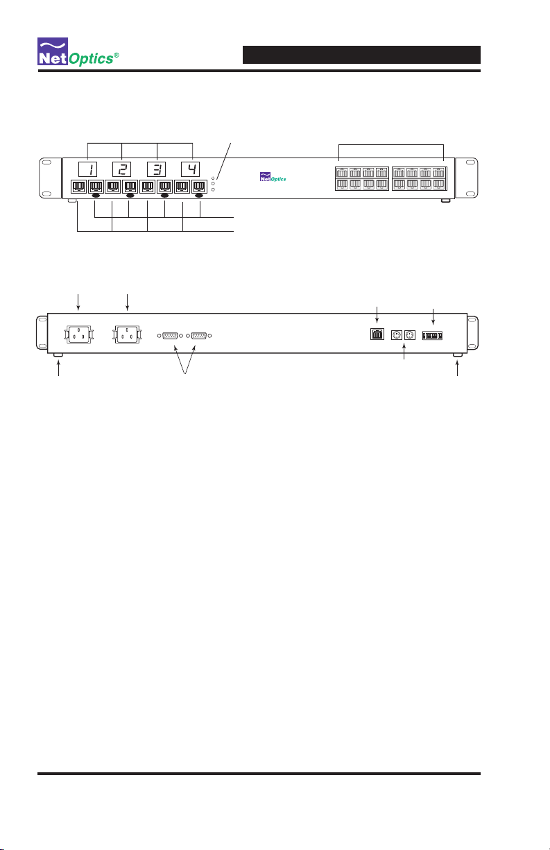
Product Diagrams
Monitor Port LED Displays Power LEDs Span Port Connectors
4xN 10/100/1000 Span Port iMatrix Switch
2
Daisy ChainDaisy Chain
Monitor 2Monitor 1
1
Daisy ChainDaisy Chain
Monitor 4Monitor 3
Figure 1: Front Panel ISW-CU3-S4X16
Power Plug
Rubber Feet
(removable)
Power Plug
CONTROL PORT 2CONTROL PORT 1
Control Ports
Figure 2: Rear Panel
LED Indicators
Monitor Port LEDs: Each Monitor Port has a 2-character LED that shows
the number of the Span port currently connected to the monitor port.
Link/Activity Indicator: If a good link is established, the LED illuminates a
steady green. If there is current activity on this link, the LED fl ashes.
10/100/1000 Indicator: If the Port is set to 10 Mbps, the LED will illuminate
orange. If the Port is set to 100 Mbps, the LED will illuminate yellow. If the
Port is set to 1000 Mbps, the LED will illuminate green.
4x16 10/100/1000 Span Port Switch
Monitor Ports
Monitor Daisy Chain Ports
34
1
2
5786
Remote Interface
Port
9
10
13 15 1614
Daisy Chain
Control Ports
11 12
DIP Switch
13456782
OFF
Rubber Feet
(removable)
PWR 1/ PWR 2: Main and Redundant Power. If the Tap is deployed with
both power supplies, both LEDs illuminate when the Tap is connected to
power. An off power LED indicates that the corresponding power supply is
not functioning or not connected.
4
Page 9

Installing the iMatrix Switch
Overview
The procedure for installing the iMatrix Switch follows these basic steps:
Plan the installation
•
Confi gure IP parameters
•
Mount the iMatrix Switch
•
Connect the Management Port
•
Connect to the network
•
Connect to the monitoring devices
•
Apply power to the iMatrix Switch
•
Check the installation
•
Installation Planning
There are two methods for connecting your iMatrix Switch:
Single iMatrix Switch Mode
• A single monitoring device to controls the Monitor Ports of a single
iMatrix Switch from one COM Port.
Daisy Chaining Mode
Allows up to three iMatrix Switches to be controlled from one monitoring
•
device or host PC.
Remote Access
The remote access features require that you assign an IP address to the
iMatrix Switch. If you are daisy chaining iMatrix Switches, you only need an
IP address for the Controller iMatrix Switch. You may also wish to assign a
netmask.
4xN 10/100/1000 Span iMatrix Switch
Chapter 2
If you plan to remotely control the iMatrix Switch over WAN, you can also set
a gateway and IP address where you plan to use the SNMP management tool.
5
Page 10

4xN 10/100/1000 Span iMatrix Switch
Confi guring the iMatrix Switch
The iMatrix Switch is confi gured with default values that allow you to install
the iMatrix Switch and then modify parameters from Web Manager or SNMP
Manager.
The defaults values are:
IP Address: 10.60.0.123
Netmask: 255.255.0.0
Monitor Ports 1-4: Gigabit
CLI username: netoptics
CLI password: netoptics
You can set all parameters, check status, and control Monitor Port connections
from the Command Line Interface. You can change most settings later from
one of the remote interfaces.
Using the Command Line Interface (CLI)
All confi guration and control options are accessible from the iMatrix Switch's
Command Line Interface. You must set a new username and password, IP
address for the iMatrix Switch, and the port speeds. Other parameters are
optional and dependent on your installation.
For security reasons, some parameters can only be set with the CLI.
Use these commands to:
•
Set CLI username and password
•
Enable or disable the remote interfaces
•
Turn character echo to the terminal emulation software on or off
If you wish to disable the Management Port and remote interfaces, you can do
so from the CLI using the Display command.
To access the iMatrix Switch CLI:
1. Make sure power to the iMatrix Switch is off.
2. Connect a PC with terminal emulation software, such as HyperTerminal,
to the iMatrix Switch Control Port 2 using the RS232 DB-9 cable supplied
with the iMatrix Switch.
6
Page 11

DB9 Control Port 2
4xN 10/100/1000 Span iMatrix Switch
CONTROL PORT 2CONTROL PORT 1
Figure 9: Connecting to the CLI
3. Launch your terminal emulation software and set the communication
parameters to:
19200 baud
8 data bits
No parity
1 stop bit
No fl ow control
3. Connect power to the iMatrix Switch. The CLI banner and login prompt
appears.
*************************************
* Net Optics Command Line Interface *
*************************************
Login:
Password:
Figure 9: Login and Password Prompts
13456782
OFF
To COM port on monitoring device or computer
4. Type netoptics and press Enter.
5. At the password prompt, type netoptics and press Enter. The NetOp-
tics: prompt appear.
To change the username and password:
1. Change the username by typing the following command:
set username <username>
where <username> is your new username.
7
Page 12

4xN 10/100/1000 Span iMatrix Switch
2. Change the password by typing the following command:
set password <password>
where <password> is your new password.
3. Record the username and password in a secure location.
To set the iMatrix Switch IP address:
1. Type set ip <ip address> where <ip address> is the IP address you are
assigning to the iMatrix Switch and press Enter.
For example, typing set ip 10.60.0.100 sets the iMatrix Switch IP address
to 10.60.0.100.
To display current settings:
1. Type show set and press Enter. The CLI displays the current settings
similar to the example in Figure 10.
show set
IP Address: 10.60.0.123
Netmask: 255.255.0.0
Manager: 10.10.1.40
Gateway: 10.60.0.118
HW Version: REV 1.00
SW Version: REV 1.00
Port 1 Parameters: Gigabit
Port 2 Parameters: Gigabit
Port 3 Parameters: Gigabit
Port 4 Parameters: Gigabit
Figure 10: Show Set Command Example
To disable the remote interfaces:
1. Type show display and press Enter to view the current setting. The default
value is Display: ON.
2. Type display and press Enter. Access to the iMatrix Switch from remote
interfaces will be blocked.
3. To restore the display and remote interfaces, type display and press Enter.
8
Page 13

4xN 10/100/1000 Span iMatrix Switch
To use the Help command:
1. Type Help and press Enter at the NetOptics prompt. The list of help
topics is displayed.
NetOptics: help
*************************************
* Net Optics Command Line Interface *
*************************************
Usage: “help”
<variable>:
set - Configure various options.
reset - Reset options.
switch - Switch control commands.
show - show current configuration and
status.
echo - Turn on or off echoing of
characters.
display- Toggle to enable/disable network
- accessibility.
help - This help screen.
Figure 11: iMatrix Switch CLI Help Menu
5. To view the syntax for changing the iMatrix Switch’s confi guration param-
eters, type help set and press Enter.
6. To view the syntax for other commands, type help followed by the com-
mand. For more information on CLI commands, see Appendix B.
9
Page 14
4xN 10/100/1000 Span iMatrix Switch
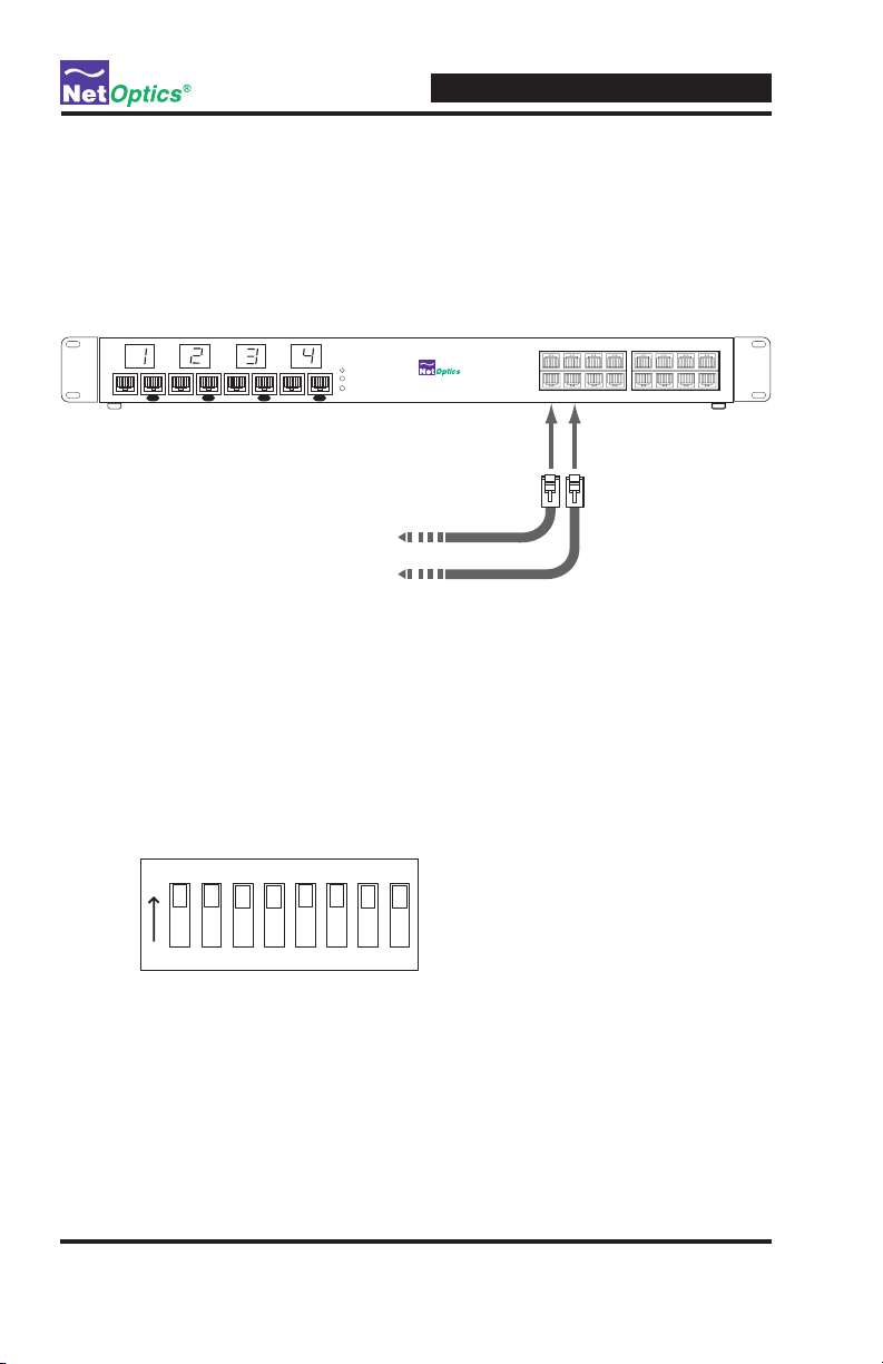
Connecting to Switch Span Ports
1. Connect Span Port 1 of the iMatrix Switch to the appropriate Span port on
your switch using CAT5e straight-through cables.
2. Repeat Step 1 for each additional network switch Span port you wish to
monitor.
2
1
Daisy ChainDaisy Chain
Monitor 2Monitor 1
Daisy ChainDaisy Chain
Monitor 4Monitor 3
To switch Span Port
To switch Span Port
Figure 4: Connecting Span Ports
4x16 10/100/1000 Span Port Switch
Connecting to the Monitoring Device
You need to connect the iMatrix Switch to the input ports (NICs) of the monitor device and connect Control Port 2 to a COM port on the monitoring device
or computer where you access the CLI.
1
5786
9
13 15 1614
11 12
10
34
2
1. Verify that the DIP switch located on the rear of the unit is set as shown in
Figure 5 below.
/
1 3 4 5 6 7 8 2
.
Figure 5: DIP Switch Settings for Single iMatrix Switch (Controller)
Note: ________________________________________________________________
DIP switches 3 through 8 must remain in the ON position.
______________________________________________________________________
10
Page 15

2. Connect a CAT5e cable to the iMatrix Switch Monitor Port 1 and the input
port of the monitoring device.
3. Repeat Step 3 above to connect Monitor Ports 2 through 4 of the iMatrix
Switch to a monitoring device.
2
Daisy ChainDaisy Chain
Monitor 2Monitor 1
1
Daisy ChainDaisy Chain
Monitor 4Monitor 3
To monitoring device NIC 1
Figure 7: Connecting Monitor Ports
4. Supply power to the iMatrix Switch using the power cords included with
the unit. Verify that the Power LEDs illuminate.
4xN 10/100/1000 Span iMatrix Switch
4x16 10/100/1000 Span Port Switch
To monitoring device NIC 4
To monitoring device NIC 3
To monitoring device NIC 2
1
5786
34
2
9
13 15 1614
11 12
10
Connecting the Remote Interface Port
In order to access the remote interfaces, you must connect the Remote Interface Port to a network switch or hub as shown in Figure 8.
CONTROL PORT 2CONTROL PORT 1
To network switch or hub
Figure 8: Connecting the Remote Interface Port
Note: ________________________________________________________________
Access to the remote interface is controller by the Display command in the
CLI. To have access to the remote interfaces, make sure the Display option is
set to ON.
______________________________________________________________________
11
13456782
OFF
Page 16

Daisy Chaining iMatrix Switches
You have the option of connecting as many as three switches together for
control by a single monitoring device or computer. It does not matter if you
are connecting the monitoring ports to one device or separate devices.
In a daisy chain confi guration, one iMatrix Switch serves as the Controller
to one or two Client iMatrix Switches. The Controller/Client relationship is
set with the DIP switches on the rear of the iMatrix Switch. iMatrix Switches
are set to function as a Controller by default. Network traffi c is passed from
the Clients to the Controller and control is sent through the Controller to the
Clients.
The basic steps to daisy chaining iMatrix Switches are:
1. Connect the Controller iMatrix Switch as described in the previous
sections.
2. Connect the Controller and Client Control Ports
3. Connect the Controller and Client Monitor Ports
4. Connect the additional Span Ports
4xN 10/100/1000 Span iMatrix Switch
To daisy chain iMatrix Switches:
1. Confi gure and install the Controller iMatrix Switch as described in the
preceding sections.
2. Choose the iMatrix Switch you will use as Client 1 and set the DIP switch
positions (located on rear of unit) as shown in Figure 9. If you are installing a third switch, set the DIP switch as shown in Figure 9 for Client 2.
3. Connect CAT5e cables between the Daisy Chain Ports of iMatrix Switch 1
and the Monitor Ports of iMatrix Switch 2. If you are connecting a third
iMatrix Switch, connect CAT5e cables between the Daisy Chain Ports of
iMatrix Switch 2 and the Monitor Ports of iMatrix Switch 3 (see Figure 9).
12
Page 17

4xN 10/100/1000 Span iMatrix Switch
34
1
2
2
1
Daisy ChainDaisy Chain
Monitor 2Monitor 1
Daisy ChainDaisy Chain
Monitor 4Monitor 3
4x16 10/100/1000 Span Port Switch
iMatrix Switch Client 2
5786
Client 2 DIP Switch Settings
9
13 15 1614
11 12
10
13456782
OFF
9
13 15 1614
11 12
10
34
1
2
2
1
Daisy ChainDaisy Chain
Monitor 2Monitor 1
Daisy ChainDaisy Chain
Monitor 4Monitor 3
4x16 10/100/1000 Span Port Switch
iMatrix Switch Client 1
5786
Client 1 DIP Switch Settings
13456782
OFF
9
13 15 1614
11 12
10
34
1
2
2
1
Daisy ChainDaisy Chain
Monitor 2Monitor 1
Daisy ChainDaisy Chain
Monitor 4Monitor 3
4x16 10/100/1000 Span Port Switch
Controller iMatrix Switch
5786
Master DIP Switch Settings
13456782
To monitoring device
To monitoring device
To monitoring device
To monitoring device
OFF
Figure 9: Connecting Daisy Chained Monitor Ports
4. Connect the supplied Mini-DIN cable between Daisy Chain Port OUT of
the Controller iMatrix Switch and Daisy Chain Port IN of iMatrix Switch
Client 1.
If you are installing a third iMatrix, connect the supplied Mini-DIN cable
between Daisy Chain Port OUT of iMatrix Switch 2 and Daisy Chain Port
IN of iMatrix Switch 3 (see Figure 10).
13
Page 18

4xN 10/100/1000 Span iMatrix Switch
CONTROL PORT 2CONTROL PORT 1
CONTROL PORT 2CONTROL PORT 1
CONTROL PORT 2CONTROL PORT 1
Figure 10: Connecting the Daisy Chain Control Ports
5. Supply power to the iMatrix Switch using the power cords included with
the unit. Verify that the Power LEDs illuminate.
13456782
OFF
13456782
OFF
13456782
OFF
14
Page 19

4xN 10/100/1000 Span Port iMatrix Switch
Chapter 3
Using iMatrix Switch Web Manager
Overview
This chapter describes how to monitor and control individual iMatrix Switches
using Web Manager. The following topics are covered:
•
Accessing Web Manager
•
Viewing iMatrix Switch Status
•
Controlling iMatrix Switch Connections
•
Confi guring the iMatrix Switch
Web Manager is the browser-based interface that allows you to change confi gu-
ration settings, view status, and control which Span ports are connected to the
monitoring devices.
Note: ____________________________________________________________________
To access Web Manager, the Display option in the CLI must be set to ON. For
more information, see Using the Command Line Interface on page 4.
__________________________________________________________________________
Accessing Web Manager
Web Manager is a browser-based interface that provides access to any iMatrix
Switch with an IP address accessible from the computer running Web Manager.
Web Manager supports all common browsers.
To access Web Manager:
1. Open an Internet browser on your computer.
2. Enter the iMatrix Switch’s IP address in the URL box and press Enter. The
default IP address is 10.60.0.123. The Web Manager page appears as shown in
Figure 11.
15
Page 20

4xN 10/100/1000 Span Port iMatrix Switch
Figure 11: Web Manager Page
To save any changes to the iMatrix Switch, you must click Submit Changes. To
update the display, click your browser's refresh button.
Viewing Switch Status
You can view iMatrix Switch information from the Switch Status section of Web
Manager. The following table explains the status fi elds.
Field Name Value Description
Total Switches 1 - 4 Indicates the number of switches confi gured
Total Data Port 1 - 16 Display the total number of ports available for
Switch 1 Model - Displays the model of the switch
Switch 2 Model - Displays the model of the switch
Switch 3 Model - Displays the model of the switch
this switch model or the total number of Span
ports available in a daisy-chain confi guration.
16
Page 21

4xN 10/100/1000 Span Port iMatrix Switch
Field Name Value Description
Switch Hardware
Version
Switch Software
Version
Switch Control
Web Manager lets you set which data port is connected to the Monitor Port. To
change the network link you are monitoring, enter the number of the data port for
the link and click Submit Changes.
To disconnect the Monitor Port from all data ports, select Yes from the Reset All
Switches drop-down menu and click Submit Changes.
Confi guring the iMatrix Switch
Web Manager allows you to set the IP parameters for the switch. To change a setting, enter the IP address in the text box and click Submit Changes. The following
table explains each available option.
Field Name Function/Value Description
IP Address 0.0.0.0 IP address of the iMatrix Switch. The de-
Net Mask 0.0.0.0 Displays current Net Mask of the
Manager IP
Address
Gateway IP
Address
0.0.0.0 IP address of the computer running
0.0.0.0 Displays the IP address of the current
Displays the hardware version of the switch
Displays the software version of the switch
fault IP address is 10.60.0.123. You can
change the IP address by typing a new IP
address in the text box.
iMatrix Switch. The default Net Mask is
255.255.0.0. You can change the Net
Mask by typing a new Net Mask in the
text box.
iMatrix System Manager over a WAN.
You can change the IP address by typing
a new IP address in the text box.
WAN Gateway. You can change the
Gateway by typing a new IP address in
the text box.
17
Page 22

Message Board
You can post a message about the iMatrix Switch in the Message Board text box.
Anyone who open Web Manager for this iMatrix Switch will see your message.
To enter a message, simple click in the text box and type your message.
4xN 10/100/1000 Span Port iMatrix Switch
18
Page 23

Using System Manager
Overview
This chapter describes how to install and use Net Optics' System Manager, which
allows you to change settings, view status, and retrieve data remotely from multiple Net Optics iMatrix Switch devices. The following topics are covered:
•
Installing System Manager
•
Exploring System Manager
•
Creating a Group
•
Adding and Deleting iMatrix Switches
•
Using the Status Tab
•
Using the Confi guration Tab
Installing System Manager
The installation executable fi le for System Manager can be found on the CD
included with the iMatrix Switch.
To install System Manger:
1. Locate Setup.exe on the CD and double click it. The License Agreement dialog
box appears as shown in Figure 12.
4xN 10/100/1000 Span iMatrix Switch
Chapter 4
Figure 12: Net Optics System Manager License Agreement
19
Page 24

4xN 10/100/1000 Span iMatrix Switch
3. After reading the agreement, select I Agree and click Next to install System
Manager. The Welcome dialog box appears as shown in Figure 13.
Figure 13: Welcome Dialog Box
2. Click Next. The Select Installation Folder dialog box shown in Figure 14
appears.
Figure 14: Select Installation Folder
20
Page 25

4xN 10/100/1000 Span iMatrix Switch
3. To install in the default folder, make no changes to the path in the Folder: text
box. To install in a different location, either type the path in the Folder: text
box or click Browse to fi nd another location.
To check the space available for System Manager on the selected drive, click
Disk Cost.
4. To limit access to System Manager to the current user of the PC, select Just
Me. To allow access to any user logged into the PC, select Everyone.
5. Click Next. The Confi rm Installation dialog box shown in Figure 15 appears.
To continue the installation, click Next. The Progress dialog box appears as
shown in Figure 16.
Figure 15: Confi rm Installation
21
Page 26

4xN 10/100/1000 Span iMatrix Switch
Figure 16: Installation Progress
6. If you want to stop the installation, click Cancel. When the installation is complete, the Installation Complete dialog box appears as shown in Figure 17.
Figure 17: Installation Complete
7. Click Close. System Manager is now installed on your computer and there is a
Net Optics shortcut icon on your desktop.
22
Page 27

4xN 10/100/1000 Span iMatrix Switch
Exploring System Manager
This section explains the features and functions of System Manager. With System
Manager you can:
•
Create iMatrix Switch groups
•
Add and delete iMatrix Switches from the system
•
Remotely confi gure iMatrix Switches
•
View iMatrix Switch status information
•
Connect Monitor Ports to Span Ports
•
Add text information about the iMatrix Switch
NOTE ___________________________________________________________________
To access the iMatrix Switch with System Manager, the Display option in the CLI
must be set to ON. For more information, see Using the Command Line Interface
on page 4.
__________________________________________________________________________
To access System Manager:
1. Double click the System Manager icon on your PC desktop. The initial window,
shown in Figure 18, will not show any iMatrix Switches.
System Frame Information Frame
Figure 18: Initial window
The System Frame displays iMatrix Switches and iMatrix Switch Groups as you
add them to the system. The Information Frame displays Status, Confi guration
and Control information for individual iMatrix Switches.
23
Page 28

4xN 10/100/1000 Span iMatrix Switch
Tip! _____________________________________________________________________
To use pop-up menu shortcuts, click your right mouse button in the System Frame.
__________________________________________________________________________
Using the Toolbar
Figure 19 shows the System Manager toolbar.
Figure 19: Toolbar
The table below describes the headings found on the toolbar.
Tool Description
New Node Add iMatrix Switches to a group
New Group Create an iMatrix Switch group
Delete Delete iMatrix Switch from System Manager
Modify Change the iMatrix Switch name, IP address, model, and add
Refresh Refresh the data displayed in the Information Frame.
Exit Close Net Optics System Manager
About View information about System Manager
notes
Creating a Group
You can organize iMatrix Switch devices into groups for quick access. You must
create a Group before you can add iMatrix Switches to your system.
To create an iMatrix Switch group:
1. Click New Group in the toolbar as shown in Figure 20. A new group bar
appears in the System Frame as shown in Figure 21.
Figure 20: New Group
24
Page 29

4xN 10/100/1000 Span iMatrix Switch
Figure 21: Group Bar
2. Type the name of the new group and press Enter.
Deleting a Group
You can delete a group however, all iMatrix Switches in that group will also be
deleted from System Manager.
Note: ____________________________________________________________________
Deleting an iMatrix Switch from System Manager does not affect the current
operating status of the iMatrix Switch. It will continue to pass traffi c from the Span
Ports connected at the time you delete the iMatrix Switch from System Manager to
the Monitor Ports.
__________________________________________________________________________
To delete a Group:
1. Right click on the group bar of the group you want to delete.
2. Select Delete from the pop-up menu. The Group and all associated iMatrix
Switches are deleted from System Manager.
Adding iMatrix Switches
To confi gure and control iMatrix Switches with System Manager, you must add
iMatrix Switches to System Manager. Once you have added an iMatrix Switch,
you can confi gure, modify, group, and delete it from System Manager.
Note: ____________________________________________________________________
The iMatrix Switch must be connected to the network as described in Chapter 2
before it can be added to System Manager.
__________________________________________________________________________
25
Page 30

4xN 10/100/1000 Span iMatrix Switch
To add an iMatrix Switch to the system:
1. Select the Group to which you want to add an iMatrix Switch by clicking the
group bar.
2. Click New Node in the toolbar as shown in Figure 22. The New Node dialog
box appears as shown in Figure 23.
Figure 22: Adding a New iMatrix Switch
Figure 23: New iMatrix Switch
2. Enter a name for the iMatrix Switch you are adding in the Node Name text
box. Each Node Name in the system must be unique.
3. Enter the IP address of the iMatrix Switch in the IP Address text box. Make
sure the IP address is unique on the network.
4. Select your model of the iMatrix Switch from the Product drop-down list.
5. Enter any relevant information about the iMatrix Switch in the Notes text box.
6. Check your settings and click Create. The System Manger now shows the
iMatrix Switch in the system similar to Figure 24.
26
Page 31

4xN 10/100/1000 Span iMatrix Switch
Figure 24: Net Optics System Manager with an iMatrix Switch
The indicator to the right of the iMatrix Switch picture blinks green when the
iMatrix Switch is functioning normally. If there is an alarm condition on the
iMatrix Switch, the indicator blinks red. If System Manager cannot communicate with the iMatrix Switch, the graphic of the switch appears grayed. Check
that the iMatrix Switch is connected to the network and verify the confi guration
information.
7. Repeat Steps 1-6 for each iMatrix Switch you are adding to System Manager.
Tip! _____________________________________________________________________
To change the order in which iMatrix Switches appear in the System Frame, click
and drag iMatrix Switches into the desired order.
__________________________________________________________________________
27
Page 32

Deleting an iMatrix Switch
You can delete an iMatrix Switch from System Manager when you remove an
iMatrix Switch from your network. If you have removed an iMatrix Switch from
the network, System Manager continues to poll the iMatrix Switch’s IP address for
data until you delete the iMatrix Switch from System Manager.
To delete an iMatrix Switch from System Manager:
1. Select the iMatrix Switch you want to delete by clicking its icon.
2. Click Delete in the toolbar. A confi rmation dialog box appears.
Figure 25: Delete Confi rmation
3. Click Ye s to delete the iMatrix Switch from System Manager.
Confi guring an iMatrix Switch
You can set confi guration parameters of an iMatrix Switch in the system from the
Confi gure tab.
4xN 10/100/1000 Span iMatrix Switch
To confi gure the iMatrix Switch:
1. Click on the icon of the iMatrix Switch you want to confi gure and click the
Confi gure tab as shown in Figure 26.
Figure 26: iMatrix Switch Confi gure Tab
28
Page 33

4xN 10/100/1000 Span iMatrix Switch
2. For the parameter you wish to confi gure, click on the corresponding value fi eld.
3. Select an option from the drop-down list or enter a new value from your
keyboard.
4. The new confi guration parameters take effect next time System Manager polls
the iMatrix Switch.
The table below describes the confi guration options on the Confi gure Tab.
Host Name The name of the iMatrix Switch
IP Address The IP address of the iMatrix Switch.
Netmask The IP address netmask.
Gateway IP Address The IP address of the gateway.
System Manager IP
Address
Monitor Port 1
Parameter
Monitor Port 2
Parameter
Monitor Port 3
Parameter
Monitor Port 4
Parameter
The IP address of the host PC running System Manager
or third-party SNMP management tool.
The speed setting for Monitor Port 1 (GigaBit, 10 Mbps, or
100 Mbps).
The speed setting for Monitor Port 2 (GigaBit, 10 Mbps, or
100 Mbps).
The speed setting for Monitor Port 3 (GigaBit, 10 Mbps, or
100 Mbps).
The speed setting for Monitor Port 4 (GigaBit, 10 Mbps, or
100 Mbps).
Viewing iMatrix Switch Information
System Manager allows you to view the current iMatrix Switch confi guration
information, including the Monitor Port connections.
To view iMatrix Switch information:
1. Click the image of the iMatrix Switch you want to view in the System Frame. A
window similar to Figure 27 appears.
29
Page 34

4xN 10/100/1000 Span iMatrix Switch
Figure 27: iMatrix Switch Status Tab
The Status tab is a read-only list of information from the iMatrix Switch. Use the
scroll bar and arrows to view the entire list if necessary.
TIP! _____________________________________________________________________
Fields that have been updated since the last refresh appear with a circle and arrow
just to the left of the value fi eld.
__________________________________________________________________________
The following table explains the status fi elds.
Switch 1 Model Model of the Controller iMatrix Switch.
Switch 2 Model Model of the fi rst Client iMatrix Switch, if present.
Switch 3 Model Model of the second Client iMatrix Switch, if present.
Hardware Version Hardware version of the Controller iMatrix Switch. The hard-
Software Version Software version of the Controller iMatrix Switch. The soft-
Monitor Port 1
Data Port
Monitor Port 2
Data Port
Monitor Port 3
Data Port
ware version is not displayed for Client iMatrix Switches.
ware version is not displayed for Client iMatrix Switches.
The Span Port currently connected to Monitor Port 1. To
change the Monitor Port connection, use the Control Tab.
The Span Port currently connected to Monitor Port 2. To
change the Monitor Port connection, use the Control Tab.
The Span Port currently connected to Monitor Port 3. To
change the Monitor Port connection, use the Control Tab.
30
Page 35

4xN 10/100/1000 Span iMatrix Switch
Monitor Port 4
Data Port
Total Data Ports Total number of Data Ports on the iMatrix Switch including
Total Switches Total number of daisy-chained Client iMatrix Switches plus
The Span Port currently connected to Monitor Port 4. To
change the Monitor Port connection, use the Control Tab.
any ports on daisy-chained Client iMatrix Switches.
the Controller iMatrix Switch (1-3).
Modifying an iMatrix Switch
You can change the IP address and other basic iMatrix Switch confi guration
parameters from the Modify iMatrix Switch dialog box.
To modify the iMatrix Switch confi guration:
1. In the System Frame, click on the image of the iMatrix Switch you want to
change.
2. Click Modify in the toolbar. The Modify Node dialog box appears as shown in
Figure 28.
Figure 28: Modify iMatrix Switch
3. Make the desired changes and click Save Change.
31
Page 36

Controlling Switch Connections
Use the Control Tab to connect the Monitor Ports to a connected Span Port. You
can connect four monitoring devices to any four Span Ports on the switch or
daisy-chained switches.
To connect a Monitor Port to a Span Port:
1. Click the Control tab. Figure 29 shows the Control Tab for a 2xN iMatrix
Switch. The 4xN GigaBit Copper Span Switch will show four Monitor Port
columns.
4xN 10/100/1000 Span iMatrix Switch
Figure 29: Control Tab
2. Click a port in the Mon. 1 column to connect the device on Monitor Port 1
to a Span Port. The example in Figure 30 shows Monitor Port 1 connected to
Span Port 2.
32
Page 37

4xN 10/100/1000 Span iMatrix Switch
Figure 30: Connecting Monitor Port 1
2. Click a port in the Mon. 2 column to connect the device on Monitor Port 2 to a
Span Port. The example in Figure 31 shows Monitor Port 2 connected to Span
Port 4.
Figure 31: Connecting Monitor Port 2
3. Repeat for Steps 1 and 2 for Mon. 3 and Mon. 4 columns. You cannot connect
more than one Monitor Port to a Span Port.
33
Page 38

4. To clear all port connections, click Reset All.
Entering Port Names and Notes
You have the option of naming the Span Ports and entering a note. Naming the
Span Ports will make switch management easier. Add notes to the Span Port connection to communicate important information to other users of System Manager.
To enter Span Port Names and Notes:
1. Click the text box next to the Span Port number you wish to name.
2. Enter the name of the Span Port and press Enter.
3. Click the text box in the Note column to add a note about this Span Port.
4. You can also enter a message about this particular switch in the Message Board
text box at the bottom of the page.
4xN 10/100/1000 Span iMatrix Switch
34
Page 39

Specifi cations
Electrical
Power Input
100-240VAC, 0.5A, 47-63Hz
Environmental
Operating Temperature
0˚C to 55˚C
Storage Temperature
-10˚C to 70˚C
Relative Humidity
5% min, 95% max, non-condensing
Mechanical
Dimensions
1.75” high x 15.75” deep x 17” wide
Cable Interfaces:
Copper Cable Type: 22-24 AWG unshielded twisted pair cable, CAT5e
Link Distance Supported: 90 meters (includes network and monitor
segments)
Connectors:
(4) RJ45, 8-pin connectors (monitor ports)
(4) RJ45, 8-pin connectors (monitor daisy chain ports)
(16) RJ45, 8-pin connectors (Span ports)
(2) Mini-DIN, 4-pin connectors (daisy-chain control
(2) DB9 serial control interfaces
Indicators
(4) 2-character LED
(20) Link/Activity LEDs
(2) Power LEDS
4xN 10/100/1000 Span iMatrix Switch
Appendix A
Specifi cations and Models
35
Page 40

Software
Command Line Interface
Any terminal emulation software
iMatrix Web Manager
Any browser
iMatrix System Manager
Windows 98, Windows 2000, Windows XP
Certifi cations
Fully RoHS compliant
4xN 10/100/1000 Span iMatrix Switch
36
Page 41

4xN 10/100/1000 Span iMatrix Switch
Appendix B
Command Line Interface
Command Sub-Command Syntax Description
Help Set help set Displays the set command
Reset help reset Displays the reset command
Show help show Displays the show command
Echo help echo Displays the echo command
Display help display Displays the display command
Set IP set ip <address> Where <address> is the IP
Netmask set netmask
<address>
Gateway set gateway
<address>
Manager set manager
<address>
Parameter Port set parameter
port <port ID>
<parameter>
Username set username
<username>
Password set password
<password>
Reset Storage reset storage Resets confi guation to factory
Switch reset switch Disconnects all Monitor Ports
options.
options.
options.
options.
options.
address of the iMatrix Switch.
Where <address> is the IP
address of the netmask.
Where <address> is the IP
address of the gateway.
Where <address> is the IP
address of the remote manager.
Where <port ID> is 1, 2, 3, or 4
and <parameter> is
0 = GigaBit
1 = 10 Mbps
2 = 100 Mbps
3 = 1000 Mbps
Where <username> is the
authorized user's name, 9
characters or less.
Where <password> is the
authorized user's password, 9
characters or less.
defaults.
from any data ports.
37
Page 42

4xN 10/100/1000 Span iMatrix Switch
Command Sub-Command Syntax Description
Switch Monitor
Port
Show Set show set Displays currents settings.
Switch show status Displays current data port con-
Display show display Displays the display setting.
User show user Displays current user logged
Echo n/a echo <on/off> Echo off stops typed character
Display n/a display Toggles the remote interface
switch monitor
<monitor> port
<port ID>
Sets which data port is monitored where <monitor> is 1,
2, 3, or 4 and <port ID> is the
data port number
nected to the monitor port.
Display OFF disables remote
interfaces.
into the CLI.
from being displayed on the
screen.
on and off.
38
Page 43

Notes:
4xN 10/100/1000 Span iMatrix Switch
39
Page 44

www.netoptics.com
© 2006 by Net Optics, Inc. All Rights Reserved.
 Loading...