

Page 1
User Guide
iBypass HD
Eight segment bypass switch
Doc. 800-0126-001 Rev 5 PUBIBP8000U 4/10
Page 2

PLEASE READ THESE LEGAL NOTICES CAREFULLY.
By using a Net Optics iBypass HD device you agree to the terms and conditions of usage set forth by Net Optics, Inc.
No licenses, express or implied, are granted with respect to any of the technology described in this manual. Net Optics retains all intellectual
property rights associated with the technology described in this manual. This manual is intended to assist with installing Net Optics products into
your network.
Trademarks and Copyrights
© 2008-2010 by Net Optics, Inc. Net Optics is a registered trademark of Net Optics, Inc. iBypass HD is a trademark of Net Optics, Inc. Additional
company and product names may be trademarks or registered trademarks of the individual companies and are respectfully acknowledged.
Additional Information
Net Optics, Inc. reserves the right to make changes in specications and other information contained in this document without prior notice. Every
effort has been made to ensure that the information in this document is accurate.
Page 3

iBypass HD
Contents
Chapter 1
Introduction .............................................................................................. 1
Key Features . . . . . . . . . . . . . . . . . . . . . . . . . . . . . . . . . . . . . . . . . . . . . . . . . . . . . . . . . . . . . . . . . . . . . . . . . . . . 2
About this Guide . . . . . . . . . . . . . . . . . . . . . . . . . . . . . . . . . . . . . . . . . . . . . . . . . . . . . . . . . . . . . . . . . . . . . . . . . 3
Bypass Modes . . . . . . . . . . . . . . . . . . . . . . . . . . . . . . . . . . . . . . . . . . . . . . . . . . . . . . . . . . . . . . . . . . . . . . . . . . . 3
Power Loss Bypass . . . . . . . . . . . . . . . . . . . . . . . . . . . . . . . . . . . . . . . . . . . . . . . . . . . . . . . . . . . . . . . . . . . 4
Heartbeat Bypass . . . . . . . . . . . . . . . . . . . . . . . . . . . . . . . . . . . . . . . . . . . . . . . . . . . . . . . . . . . . . . . . . . . . 5
Forced Bypass On . . . . . . . . . . . . . . . . . . . . . . . . . . . . . . . . . . . . . . . . . . . . . . . . . . . . . . . . . . . . . . . . . . . . 5
Tap Mode During Bypass . . . . . . . . . . . . . . . . . . . . . . . . . . . . . . . . . . . . . . . . . . . . . . . . . . . . . . . . . . . . . . . . . . 5
Trafc Statistics . . . . . . . . . . . . . . . . . . . . . . . . . . . . . . . . . . . . . . . . . . . . . . . . . . . . . . . . . . . . . . . . . . . . . . . . . 6
CRC Forwarding . . . . . . . . . . . . . . . . . . . . . . . . . . . . . . . . . . . . . . . . . . . . . . . . . . . . . . . . . . . . . . . . . . . . . . . . . 6
Jumbo Packets . . . . . . . . . . . . . . . . . . . . . . . . . . . . . . . . . . . . . . . . . . . . . . . . . . . . . . . . . . . . . . . . . . . . . . . . . . . 6
Link Fault Detect . . . . . . . . . . . . . . . . . . . . . . . . . . . . . . . . . . . . . . . . . . . . . . . . . . . . . . . . . . . . . . . . . . . . . . . . 6
Bypass Detect . . . . . . . . . . . . . . . . . . . . . . . . . . . . . . . . . . . . . . . . . . . . . . . . . . . . . . . . . . . . . . . . . . . . . . . . . . . 6
iBypass HD Management . . . . . . . . . . . . . . . . . . . . . . . . . . . . . . . . . . . . . . . . . . . . . . . . . . . . . . . . . . . . . . . . . . 7
The iBypass HD Front Panel . . . . . . . . . . . . . . . . . . . . . . . . . . . . . . . . . . . . . . . . . . . . . . . . . . . . . . . . . . . . . . . 7
The iBypass HD Rear Panel . . . . . . . . . . . . . . . . . . . . . . . . . . . . . . . . . . . . . . . . . . . . . . . . . . . . . . . . . . . . . . . . 8
Chapter 2
Installing the iBypass HD ......................................................................... 9
Plan the Installation . . . . . . . . . . . . . . . . . . . . . . . . . . . . . . . . . . . . . . . . . . . . . . . . . . . . . . . . . . . . . . . . . . . . . . 10
Unpack and Inspect the iBypass HD device . . . . . . . . . . . . . . . . . . . . . . . . . . . . . . . . . . . . . . . . . . . . . . . . . . . 10
Install DBMs . . . . . . . . . . . . . . . . . . . . . . . . . . . . . . . . . . . . . . . . . . . . . . . . . . . . . . . . . . . . . . . . . . . . . . . . . . . 11
Install SFP Modules . . . . . . . . . . . . . . . . . . . . . . . . . . . . . . . . . . . . . . . . . . . . . . . . . . . . . . . . . . . . . . . . . . . . . 11
Rack Mount the iBypass HD device . . . . . . . . . . . . . . . . . . . . . . . . . . . . . . . . . . . . . . . . . . . . . . . . . . . . . . . . . 12
Connect Power to the iBypass HD . . . . . . . . . . . . . . . . . . . . . . . . . . . . . . . . . . . . . . . . . . . . . . . . . . . . . . . . . . 12
Installation in a Restricted Access Location in Finland and Norway . . . . . . . . . . . . . . . . . . . . . . . . . . . . . . . . 14
Warnings and Symbols . . . . . . . . . . . . . . . . . . . . . . . . . . . . . . . . . . . . . . . . . . . . . . . . . . . . . . . . . . . . . . . . . . . 15
Connect the Local CLI Interface . . . . . . . . . . . . . . . . . . . . . . . . . . . . . . . . . . . . . . . . . . . . . . . . . . . . . . . . . . . . 15
Connect the Remote CLI Interface . . . . . . . . . . . . . . . . . . . . . . . . . . . . . . . . . . . . . . . . . . . . . . . . . . . . . . . . . . 17
Log into the CLI . . . . . . . . . . . . . . . . . . . . . . . . . . . . . . . . . . . . . . . . . . . . . . . . . . . . . . . . . . . . . . . . . . . . . . . . 19
Use the CLI Help Command . . . . . . . . . . . . . . . . . . . . . . . . . . . . . . . . . . . . . . . . . . . . . . . . . . . . . . . . . . . . . . . 19
Congure the iBypass HD Using the CLI . . . . . . . . . . . . . . . . . . . . . . . . . . . . . . . . . . . . . . . . . . . . . . . . . . . . 20
Change the iBypass HD Login Password . . . . . . . . . . . . . . . . . . . . . . . . . . . . . . . . . . . . . . . . . . . . . . . . . 21
Assign a New iBypass HD IP Address, Netmask, and Gateway IP Address . . . . . . . . . . . . . . . . . . . . . . 21
Change the SSH Password . . . . . . . . . . . . . . . . . . . . . . . . . . . . . . . . . . . . . . . . . . . . . . . . . . . . . . . . . . . . 21
Change Port Modes . . . . . . . . . . . . . . . . . . . . . . . . . . . . . . . . . . . . . . . . . . . . . . . . . . . . . . . . . . . . . . . . . . 22
Set the Current Date and Time . . . . . . . . . . . . . . . . . . . . . . . . . . . . . . . . . . . . . . . . . . . . . . . . . . . . . . . . . 22
Page 4

iBypass HD
Save and Load the iBypass HD Congurations . . . . . . . . . . . . . . . . . . . . . . . . . . . . . . . . . . . . . . . . . . . . 22
Manage the Security Key . . . . . . . . . . . . . . . . . . . . . . . . . . . . . . . . . . . . . . . . . . . . . . . . . . . . . . . . . . . . . 23
Use the CLI Command History Buffer . . . . . . . . . . . . . . . . . . . . . . . . . . . . . . . . . . . . . . . . . . . . . . . . . . . 23
Undertand the Commit Commands . . . . . . . . . . . . . . . . . . . . . . . . . . . . . . . . . . . . . . . . . . . . . . . . . . . . . 24
Connect the iBypass HD to the Network . . . . . . . . . . . . . . . . . . . . . . . . . . . . . . . . . . . . . . . . . . . . . . . . . . . . . 25
Connect IPSs to the iBypass HD . . . . . . . . . . . . . . . . . . . . . . . . . . . . . . . . . . . . . . . . . . . . . . . . . . . . . . . . . . . 26
Conguring the Bypass Switches . . . . . . . . . . . . . . . . . . . . . . . . . . . . . . . . . . . . . . . . . . . . . . . . . . . . . . . . . . . 26
Check the Installation . . . . . . . . . . . . . . . . . . . . . . . . . . . . . . . . . . . . . . . . . . . . . . . . . . . . . . . . . . . . . . . . . . . . 26
Chapter 3
Conguring Bypass Switches Using the CLI .......................................... 27
Syntax . . . . . . . . . . . . . . . . . . . . . . . . . . . . . . . . . . . . . . . . . . . . . . . . . . . . . . . . . . . . . . . . . . . . . . . . . . . . . . . . 27
Restart the System . . . . . . . . . . . . . . . . . . . . . . . . . . . . . . . . . . . . . . . . . . . . . . . . . . . . . . . . . . . . . . . . . . . . . . . 27
Congure Bypass Switch and DBM Options . . . . . . . . . . . . . . . . . . . . . . . . . . . . . . . . . . . . . . . . . . . . . . . . . . 28
Customize Heartbeat Packets . . . . . . . . . . . . . . . . . . . . . . . . . . . . . . . . . . . . . . . . . . . . . . . . . . . . . . . . . . . . . . 29
Use Bypass Switch Pairs in High Availability (HA) Mode . . . . . . . . . . . . . . . . . . . . . . . . . . . . . . . . . . . . . . . 30
Chapter 5
Conguring AAA Servers ........................................................................ 33
Congure RADIUS and TACACS+ Servers . . . . . . . . . . . . . . . . . . . . . . . . . . . . . . . . . . . . . . . . . . . . . . . . . . 33
Appendix A
iBypass HD Specications ...................................................................... 37
Appendix B
Command Line Interface ........................................................................ 39
iBypass HD CLI Quick Reference ........................................................... 40
Page 5
iBypass HD
Chapter 1
Introduction
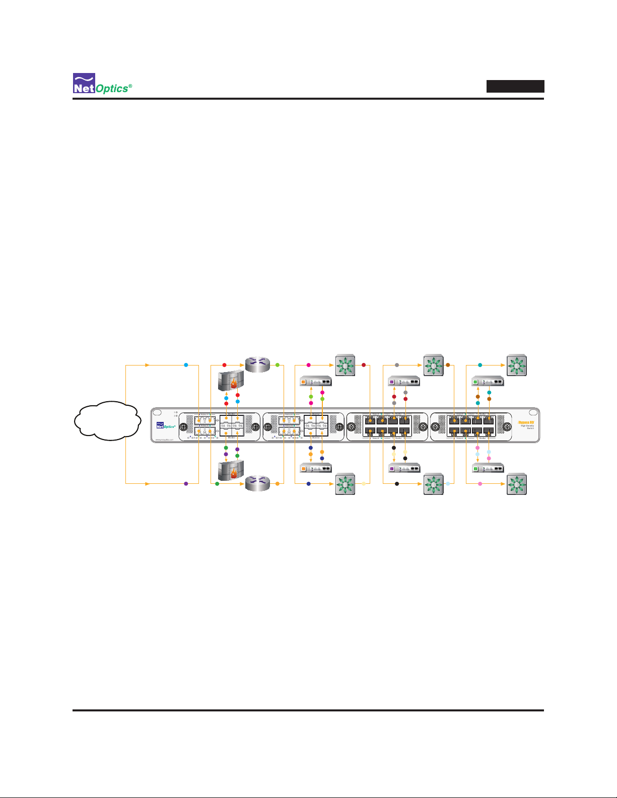
Net Optics iBypass HD is a high density solution for fail-safe attachment of in-line devices such as intrusion
preventions systems (IPSs), rewalls, and data loss prevention (DLP) appliances. (For simplicity, the acronym IPS
will be used for all such in-line devices in this manual.) The iBypass HD provides eight independent intelligent bypass
switches in a 1U form-factor, the highest bypass switch density in the industry.
A modular design enables you to congure the iBypass HD to t your environment. Dual Bypass Modules (DBMs)
enable the iBypass HD to be populated with 2, 4, or 8 bypass switches. DBMs are available with copper, singlemode
ber, and multimode ber interfaces, and they can be mixed in any combination in the iBypass HD chassis.
Besides functioning as independent bypass switches, the pair of bypass switches in each DBM can be coupled
together in a high availablity conguration, supporting failover to a backup link or to a backup IPS. The device is
enterprise-ready with a full-function management interface, making the iBypass HD is a key component for building a
comprehensive, consolidated monitoring infrastructure for both network performance management and security.
IPS
DLP
Compliance
Internet
IPS
Figure 1: A comprehensive, consolidated network monitoring infrastructure using iBypass HD
Fail-safe In-line Access
The iBypass HD provides fail-safe in-line access ports for up to eight IPSs. Each bypass switch routes data through the
IPS as if it were in-line, completely transparently. If the IPS loses power or is otherwise unable to proces the trafc in a
timely manner, the bypass switch changes to Bypass On mode, taking the IPS ofine and routing trafc directly through
the network link. When the IPS is able to process trafc again, the bypass switch automatically switches to Bypass Off
mode and routes the trafc through the IPS once again.
No Trafc Interference
The network connections in the iBypass HD are fully passive. They never affect the network trafc owing through
them—not even if the unit loses power. If the iBypass HD loses power from both of its redundant power sources, it
automatically enters Bypass On mode to keep the network trafc owing (but bypassing the IPS).
DLP
Compliance
1
Page 6

iBypass HD
Bi-Directional Heartbeat
The iBypass HD periodically sends small Heartbeat packets through attached IPSs to verify their ability to process
trafc. If a Heartbeat packet is not returned within a congurable timeout and number of retires, the IPS is assumed
to be down and Bypass On mode is entered, taking the IPS ofine. Hearbeat packets continue to be sent to the
down IPS; when they start being returned, the IPS is known to be healthy so Bypass Off mode is resumed, with
trafc going through the IPS once again. Heartbeat packets can be sent in one direction, transmitted on Port 1 and
received on Port 2, or both directions, also transmitted on Port 2 and received on Port 1. The Heartbeat packet can be
customized independently for each bypass switch, setting the packet contents, timeout, and number of retries.
High Availability Mode
The two bypasses switches in a DBM can be coupled together in a high availability (HA) mode that supports both
link redundancy and tool redundancy. If the primary link fails, the bypass switch reroutes to the secondary link. If
the primary tool fails, the trafc is routed to the secondary tool. When the primary link or tool comes back online,
they are automatically switched back into the conguration.
SFP Flexibility
DBMs for tapping ber network links have SFP transciever modules on the monitor ports, so IPSs with any media
type can be attached. Single-mode and multi-mode Gigabit ber, Gigabit copper, and 10/100/1000 copper interface
SFP modules are supported.
Enterprise-Ready Management
Enterprise networks can easily integrae the iBypass HD into the infrastructure because the device supports SSH secure
remote management, role-based access privileges, and RADIUS and TACACS+ authentication and authorization.
Key Features
Ease of Use
• 19-inch rack frame, 1U high
• Front-mounted connectors for quick and easy installation
• LED indicators show Power, Link, and Activity status
• Modular design for conguration exibility
• RMON statistics, including network utilization, packet count, and CRC errors
• Text-based command-line interface (CLI) available through RS232 serial port and remotely over secure SSH
connections
• Field-upgradeable software
• Compatible with all major manufacturers’ monitoring devices including IPSs, rewalls, protocol analyzers, probes,
and intrusion detection systems
Passive, Secure Technology
• Passive access at up to 1 Gbps
• In-line links do not interfere with the data stream or introduce a point of failure
• Optimized and tested for 10, 100, and 1000 Mbps copper and 1 Gpbs ber networks
• Universal AC or -48VDC hot-swappable, redundant power supplies to maximize uptime
• In-line links default to open under a complete power-fail condition, ensuring network availability
• FCC, CE, VCCI, C-Tick, and WEEE certied
• Fully RoHS compliant
2
Page 7
Unsurpassed Support
• Net Optics offers technical support throughout the lifetime of your purchase. Our technical support team is
available from 8:00 to 17:00 Pacic Time, Monday through Friday at +1 (408) 737-7777 and via e-mail at
ts-support@netoptics.com. Information is also available on the Net Optics Web site at www.netoptics.com.
About this Guide
Please read this entire guide before installing the iBypass HD. This guide applies to the following part numbers:
Part Number Description
IBP-8000 iBypass HD Main Chassis, 4 DBM Bays
IBP-8000-DC iBypass HD Main Chassis, 4 DBM Bays, -48V
DBM-100 DBM, iBypass HD, 10/100/1000, RJ45
DBM-200 DBM, iBypass HD, Gig, MM, 62.5μm, SFP Monitor Ports
DBM-250 DBM, iBypass HD, Gig, MM, 50μm, SFP Monitor Ports
DBM-300 DBM, iBypass HD, Gig, SM, 8.5μm, SFP Monitor Ports
Bypass Modes
A bypass switch is in Bypass Off mode during normal system operation. Trafc is routed through the attached IPS just
as if the IPS were in-line itself. The following gure shows a bypass switch in normal operation (Bypass Off mode).
iBypass HD
Bypass O
Traffic is routed through the IPS
IPS
Figure 2: Bypass Off mode – the IPS is in-line
A bypass switch is in Bypass On mode when a problem occurs. Trafc is routed directly though the network link,
bypassing the attached IPS. The following gure shows a bypass switch when a problem occurs (Bypass On mode).
3
Page 8
iBypass HD
IPS
Bypass On
Traffic bypasses the IPS
Figure 3: Bypass On mode – the IPS is off-line
Note: _________________________________________________________________________________________________
If fail_state is set to no_trafc rather than fail-to-wire, then network trafc is blocked in Bypass On mode.
_______________________________________________________________________________________________________
A bypass switch enters Bypass On mode when one of four events occurs:
• Power loss to the iBypass HD
• Link failure
• IPS application failure (can be caused by loss of power to the IPS)
• Bypass On mode forced by CLI command
Link failure and application failure are detected by the Heartbeat packet not being received when expected.
A bypass switch returns to Bypass Off mode when four conditions are met:
• The iBypass HD has power
• The network link is up
• The IPS application is running (passing Heartbeat packets)
• Bypass On mode is not forced by CLI command
These conditions are discussed in further detail in the following sections.
Power Loss Bypass
The bypass switch protects link integrity when the attached IPS or the bypass switch itself loses power. To install the
bypass switch for this type of protection, the switch should share the same power source as the monitoring appliance.
If you are using redundant power supplies for the IPS, connect the same power source to the iBypass HD device's
redundant power inputs.
4
Page 9

Heartbeat Bypass
IPS
Bypass On
Traffic bypasses the IPS
Traffic is also copied
to the monitor ports
The bypass switch protects against both physical link failure and application failure on the IPS. The bypass switch
checks the path through the IPS by sending a packet at a predetermined rate—for example, once every second—to the
IPS from monitor port 1. When the bypass switch receives the packet on monitor port 2, having passed through the IPS,
it knows the path is valid. If the bypass switch does not receive the packet as expected, three times in a row, the bypass
switch automatically enters Bypass On mode. The switch continues to send Heartbeat packets, and it returns to Bypass
Off mode when it receives a Heartbeat packet on monitor port 2.
The contents of the Heartbeat packet, the interval at which it is sent, and the number of retries that trigger Bypass On
are congurable through the CLI. Another option enables Heartbeat packets to be sent in both directions, from port 1 to
port 2, and from port 2 to port 1.
Forced Bypass On
A command can be issued over the management interface to force a bypass switch into Bypass On mode. For example,
the CLI command switch set sw=1 mode=bp_on forces switch 1 into Bypass On mode. This feature is useful if you
want to manually take the IPS ofine at any time.
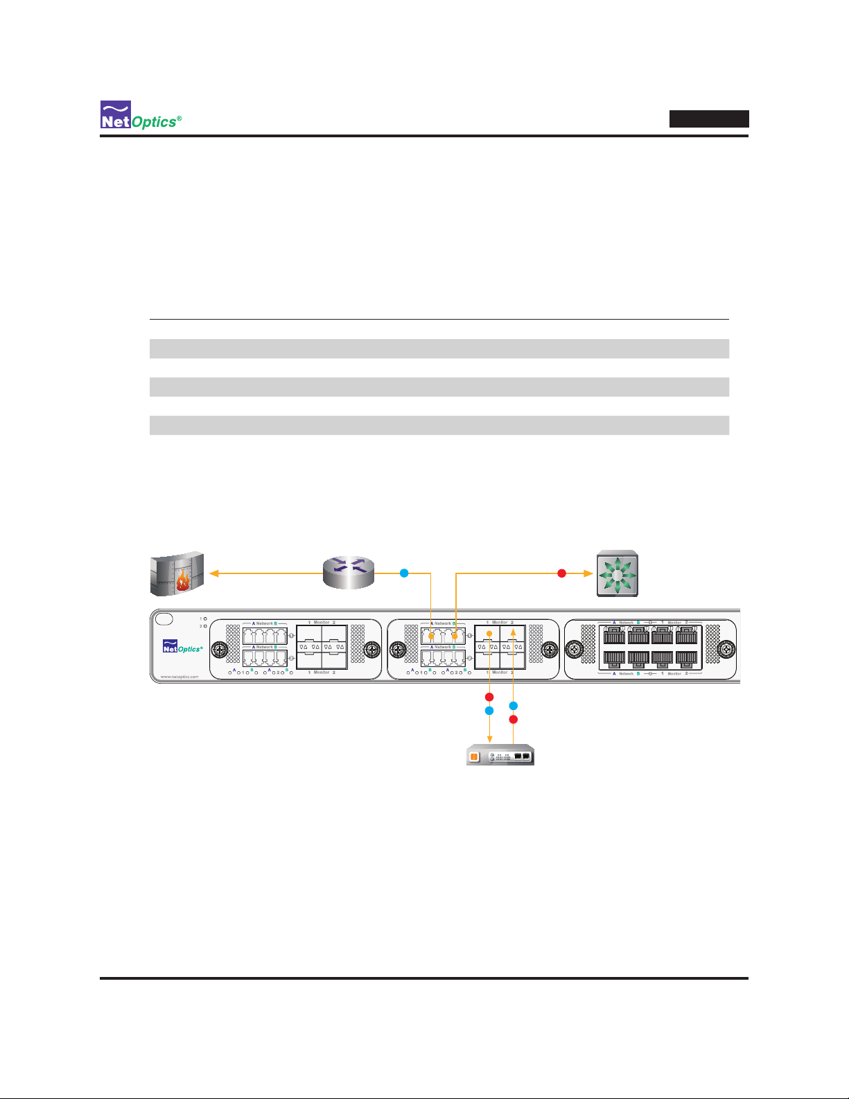
Tap Mode During Bypass
When a bypass switch is in Bypass On mode, it operates as a normal network Tap by copying the trafc received at
network port A to monitor port 1, and trafc received at network port B to monitor port 2. This function enables the
attached device to monitor network trafc out-of-band, for instance, to baseline the system prior to putting the device
in-line. The only difference from a normal network Tap is that Heartbeat packets continue to be transmitted (if the
Switch is not in Manual Bypass mode) in order to detect when the monitoring tool comes back online. If desired,
passing of trafc during Bypass On mode can be disabled through the CLI.
iBypass HD
Note: __________________________________________________________________________________________________
When using the bypass switch as a network Tap, be sure to set the Bypass Detect Feature to "OFF" so the ports remain
on constantly.
________________________________________________________________________________________________________
Figure 4: Bypass On mode showing Tap mointoring trafc
5
Page 10

iBypass HD
Trafc Statistics
The iBypass HD collects statistics about the trafc passing through each of its ports. The statistics can be viewed and
cleared through the management interface.
The trafc statistics collected by the bypass switch on each of its ports are:
• Peak trafc rate
• Time of the peak trafc
• Current bandwidth utilization
• Total number of packets
• Total number of bytes
• Number of Cyclical Redundancy Check (CRC) errors
• Number of oversize packets
Note __________________________________________________________________________________________________
The trafc statistics counters are 32 bits wide, so the maximum value of each counter is 4,294,967,295. The counters
roll over to 0 after the maximum count is reached. Be aware that, at 1 Gbps, the Total Bytes counter can roll over in as
____________________________________________________________________________________________________________________________________________________________
short a time as 0.34 seconds and the Total Packets counter in 22 seconds.
CRC Forwarding
The iBypass HD forwards all packets to the monitor ports, even packets that have CRC errors.
Jumbo Packets
The iBypass HD can be set to accept or reject jumbo packets, which are packets longer than the Ethernet standard
maximum length of 1,518 bytes. The maximum packet size passed to the monitor ports by the iBypass HD can be set
from 64 to 12,000 bytes.
Link Fault Detect
The iBypass HD supports the Net Optics Link Fault Detect (LFD) feature on the in-line network ports. When LFD is on,
if one port of an in-line pair loses link, the other port is forced to drop the link as well. This feature ensures that switches
and routers on both sides of the link see the failure so they can take remedial action such as rerouting trafc around the
failed link. This feature can be turned on or off through the management interface.
Note: __________________________________________________________________________________________________
When a port is set for autonegotiation and LFD is on, autonegotiation can take as long as 10 seconds. During this
period, the link speed can change and the Link LED might go on and off several times.
________________________________________________________________________________________________________
Bypass Detect
The Bypass Detect feature enables an IPS to be alerted when the bypass switch is in Bypass On mode. When Bypass
Detect is enabled and the switch is in Bypass On mode, monitor ports 1 and 2 are cycled off for 5 seconds followed by
on for 15 seconds. The loss of link signals the IPS that the switch has entered Bypass On mode, while the 15 seconds of
on time enable the switch to test the state of the IPS by issuing Heartbeat packets.
6
Page 11
iBypass HD Management
The iBypass HD is congured and managed using a command-line interface (CLI) that will be familiar to most network
administrators. GUI-based Indigo management tools will be available soon.
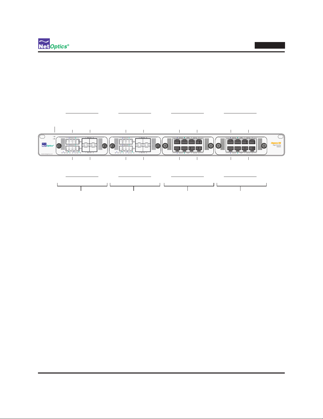
The iBypass HD Front Panel
The features of the iBypass HD front panel are shown in the following diagram.
Switch 1 Switch 3 Switch 5 Switch 7
Power LEDs
Network
Ports
(LC)
Monitor
Ports
(SFP)
Network
Ports
(LC)
Monitor
Ports
(SFP)
Network
Ports
(RJ45)
Monitor
Ports
(RJ45)
Network
Ports
(RJ45)
iBypass HD
Monitor
Ports
(RJ45)
Network
Ports
(LC)
(SX Fiber DBM)
Monitor
Ports
(SFP)
Switch 2 Switch 4 Switch 6 Switch 8
DBM 1
Network
Ports
(LC)
(LX Fiber DBM)
Monitor
DBM 2
Ports
(SFP)
Network
Ports
(RJ45)
(10/100/1000Copper DBM)
Monitor
Ports
(RJ45)
DBM 3
Network
Ports
(RJ45)
(10/100/1000 Copper DBM)
Monitor
Ports
(RJ45)
DBM 4
Figure 5: The iBypass HD Front Panel (any mix of DBM types is allowed)
Dual Bypass Modules (DBMs)
Four removable DBMs occupy four DBM slots in the chassis. Figure 5 illustrates a unit congured with two DBMs
with copper interfaces and two DBMs with ber interfaces. Each DBM contains two complete bypass switches. The
DBMs plug into an internal backplane board which contains the processor that runs the management interfaces and
manages the switches. For purposes of identication, the DBMs are numbered 1 to 4 from left to right across the
unit. The bypass switches are numbered 1 through 8 (sw1 through sw8 in the CLI), with switches 1 and 2 in DBM 1,
switches 3 and 4 in DBM 2, switches 5 and 6 in DBM 3, and switches 7 and 8 in DBM 4. Within each DBM, the oddnumbered (lower number) switch is the top row of ports and the even-numbered (high number) switch is bottom row of
ports.
Ports
Each DBM has eight ports, four for each bypass switch. Within each bypass switch, the network ports for the link
connections are designated A and B, and the monitor ports for the IPS connections are 1 and 2. The port order from left
to right is A, B, 1, 2. (In the CLI, the ports in bypass switch 1 are named sw1.A, sw1.B, sw1.1, and sw1.2. Although
the CLI is generally case sensitie, for the network ports lower case letters are also accepted, so the network ports can be
identied as sw1.a and sw1.b.) All ports support 1 Gigabit link speeds; 10/100/1000 copper ports are also supported.
Power LEDs
In the upper left-side corner of the front panel, two light-emitting diodes (LEDs) indicate the states of the two
redundant power supplies. The LED is illuminated if the power supply is supplying power; the LED is off when the
power supply is off.
7
Page 12

Port LEDs
Each port has LEDs that indicate the port's Link state and Activity. The LED on the left is the Link LED; it is
illuminated when a link is established. The LED on the right is the Activity LED; it blinks when trafc is passing
through the port. For 10/100/1000 ports, the Link LED illuminates green when the link speed is 1000 Mbps, yellow
when it is 100 Mbps, and amber when it is 10 Mbps.
The iBypass HD Rear Panel
The features of the iBypass HD rear panel are shown in the following diagram.
10/100/1000
Ethernet
Management Port
Console Port
iBypass HD
AC Model
10/100/1000
DC Model
Figure 6: The iBypass HD Rear Panel, AC models (top) and DC models (bottom)
Major features of the rear panel include:
RJ45
RS232D
Ethernet
Management Port
Console Port
RJ45
RS232D
Replaceable Fan Tray
Replaceable Fan Tray
(2) Hot Swappable
Power Supplies
(2) Hot Swappable
-48VDC Power Supplies
• Management Port—A 10/100/1000 network port for the remote management interfaces and software updates;
the CLI runs over an SSH connection through this port; Indigo management tools, when available, will connect
through this port
• Console Port —RJ45 RS232 serial port for the CLI
• Cooling Fans —Four cooling fans in a replaceable tray module; power must be removed from the unit when
replacing the cooling fans
• Power Supply Modules—Universal-input (100-240VAC, 47-63Hz) or -48VDC, hot-swappable power supplies
with integrated cooling fans; each supply can power the unit independently; dual supplies provide redundancy
to maximize uptime
8
Page 13

iBypass HD
Chapter 2
Installing the iBypass HD
This chapter describes how to install and connect iBypass HD devices. The procedure for installing the iBypass HD
follows these basic steps:
1. Plan the installation
2. Unpack and inspect the iBypass HD device
3. Install DBM modules
4. Install SFP modules
5. Rack mount the iBypass HD device
6. Connect power to the iBypass HD
7. Connect the command line interface (CLI) RS232 RJ45 port or the Management port (SSH)
8. Log into the CLI
9. Use the CLI Help command
10. Congure the iBypass HD parameters using the CLI
11. Connect the iBypass HD to the network
12. Connect IPSs to the iBypass HD
13. Congure the bypass switches
14. Check the installation
9
Page 14

Plan the Installation
Before you begin the installation of your the iBypass HD device, determine the following information:
• IP address of the iBypass HD device for the management interface; or a range of IP addresses if you are
deploying multiple the iBypass HD devices
• Net Mask for the iBypass HD
• IP address of the remote management console, if deployed over a WAN; this address will be used for SNMP
traps (when available)
• Gateway to the remote management console, if deployed over a WAN
• Port assignments for the network and monitor port connections
Make sure you have a suitable location to install the iBypass HD device. For power redundancy, use two independent
power sources.
Unpack and Inspect the iBypass HD device
Carefully unpack the iBypass HD device, power supplies, and all cables that are provided. The iBypass HD is delivered
with the following:
• (1) the iBypass HD chassis
• (1 to 4) DBMs (might already be installed in the iBypass HD chassis)
• (2) Power cords (AC model only)
• (1) Cable, 3 Meter, RJ45, CAT 5e 4-Pair (Purple)
• (1) DB9-to-RJ45 RS232 adapter for use with the CLI
• (1) iBypass HD Quick Install Guide (one sheet)
• (1) CD containing the iBypass HD User Guide (this document)
• Service Plan Reference Guide
• Registration instruction card
• Extended Warranty if purchased
iBypass HD
Check the packing slip against parts received. If any component is missing or damaged, contact Net Optics Customer
Service immediately at +1 (408) 737-7777. (Note: SFP modules are ordered and shipped separately.)
10
Page 15
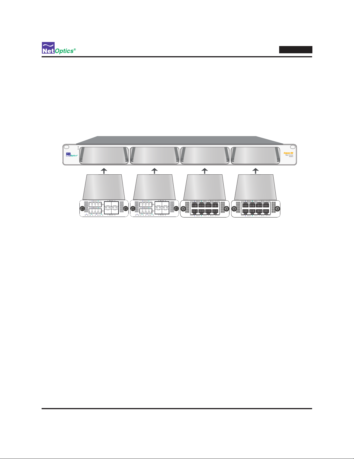
Install DBMs
If the Dual Bypass Modules (DBMs) are not already installed when you receive the unit, install them by sliding them
into the DBM slots in the front panel. DBMs can be installed in any or all of the four slots; if you do not populate all
of the slots, it does not matter which ones you leave empty. If there is a plate covering the DBM slot, remove it by
unscrewing two thumb-screws; then install the DBM module. The DBM circuit boards slide in the rails provided in the
slots. Push in the DBM rmly until you feel the connectors mate and the bezel is ush with the front panel, but do not
force them. If you encounter resistance, withdraw the module and try again, making sure to align the circuit board in the
rails and slide the module straight in. When the DBM is fully seated, fasten it to the front panel with the two captured
thumbscrews. Unused slots should be protected with blank cover plates.
iBypass HD
Slot 1 Slot 2 Slot 3 Slot 4
Figure 7: Installing Dual Bypass Modules (DBMs)
DBMs can be hot-swapped, that is, you can remove and insert DBMs while the iBypass HD is under power and operating.
Tip! ___________________________________________________________________________________________________
You can remove DBMs from the iBypass HD chassis without disconnecting the network cables. Network trafc will
keep owing because the DBM module itself is a fully passive network Tap. In ber DBMs, optical switches keep the
network paths open when the DBM is unpowered, even if it is removed from the chassis. In copper DBMs, mechanical
relays keeps the network paths open to trafc.
________________________________________________________________________________________________________
Install SFP Modules
SFP modules are shipped separately. Install them as desired in the SFP slots in the DBMs in the front of the chassis. For
each module, remove the temporary plug from the SFP slot and insert the module until it clicks into place.
Note: __________________________________________________________________________________________________
Net Optics warrants operation with SFP modules sold by Net Optics only.
________________________________________________________________________________________________________
11
Page 16

Rack Mount the iBypass HD device
The iBypass HD is designed for rack mounting in a 19-inch equipment rack and occupies one rack unit.
To mount the iBypass HD device:
1. Attach a slide rail bracket to each of the slide rails.
Use either the short or long slide rail brackets, as needed to match the depth of your rack. The slide rail bracket is
placed over the two mounting studs and adjusted to the required length. The brackets can be attached with the short
leg ahead of or behind the mounting studs, providing greater span of length adjustment.
2. Mount the slide rails to the front and rear rack posts using the provided screws and washers.
3. Slide the iBypass HD into the slide rails.
The iBypass HD locks into place. Disengaging it from the slide rails requires depressing the locking latch.
Make sure that the rack is properly grounded.
Connect Power to the iBypass HD
Supply AC power to the iBypass HD using the power cords that were included with the unit; for DC power, you must
supply your own cables. If you plan to use redundant power, make sure that you connect the power supplies to two
separate, independent power sources for maximum protection. One or both Front Panel Power LEDs are illuminated,
depending on whether you used one power supply or two.
iBypass HD
Note: __________________________________________________________________________________________________
Each AC or DC power source should be independent of the other in order to have power redundancy. If you do not
require power redundancy, the unit can be operated with a single power cord connected to a single AC or DC power
source. In this case, either AC or DC power connector on the rear of the unit can be used for the connection.
________________________________________________________________________________________________________
Use the procedures in the following sections to safely connect AC or DC power to the unit.
12
Page 17

Management Port
Console Port
iBypass HD
AC Models
Figure 8: Connecting redundant AC power supplies
Independent Power Sources
Caution: ______________________________________________________________________________________________
Use the AC power cords supplied with the product. If you use another AC power cords, they should have a wire gauge
of at least 18 and a 230VAC 2A rating. Be sure to use a three-prong cords and connect them to sockets with a good
earth grounds.
________________________________________________________________________________________________________
To connect AC input power on AC models:
1. Connect one of the AC power cords to one of the AC power connector on the rear panel.
2. Plug the other end of the cord into an AC power source.
3. Repeat Steps 1 and 2 for the other AC power cord, connecting it to the remaining AC power connector on the rear
panel.
13
Page 18

Management Port
Management Port
Console Port
AC Models
Independent Power Sources
Console Port
DC Models
Earth
Ground
iBypass HD
Power Source 1
Power Source 2
Figure 9: Connecting redundant DC power supplies
-48VDC
Return
-48VDC
Return
Caution: ______________________________________________________________________________________________
DC power cables should have a wire gauge of at least 14 and a 72VDC 6A rating.
Always connect the earth grounds rst, and keep the earth grounds connected whenever you are working on the device.
When disconnecting the device from DC power, remove the earth ground connections last.
________________________________________________________________________________________________________
To connect DC input power on DC models:
1. If you have not already done so, unpack the iBypass HD and verify that you have two appropriate DC power cables.
You also need a Phillips screwdriver to complete the installation.
2. Connect an earth ground lead to the terminal labeled with the ground symbol (
) on both DC power terminal blocks on
the rear of the chassis. Use the screwdriver to tighten the connections.
3. Connect one of the DC power cables to one of the DC power terminal blocks on the rear panel.
If present, remove the protective cover from the DC power terminal block. Connect the negative (-48VDC) side of
the cable to the terminal labeled with the minus symbol (—) and the positive (0V) side of the cable to the terminal
labeled with the plus symbol (+). Use the screwdriver to tighten the connections.
4. Repeat step 1 for the other DC power cable, connecting it to the remaining DC power terminal block on the rear
panel.
5. Carefully connect the other ends of the DC power cables to two -48VDC power sources.
If possible, turn off the power to the power source while you are making these connections. Be sure to connect the
positive sides of the cables to the positive sides of the power sources, and the negative sides of the power cables to
the negative sides of the power sources.
Installation in a Restricted Access Location in Finland and Norway
Installation in a Restricted Access Location (RAL) is required in Finland and Norway for the iBypass HD. Because
of concerns about unreliable earthing in Finland and Norway, this equipment must be installed in a RAL in these
countries. A RAL is dened as an access that can be gained only by trained service personnel who have been instructed
about the reasons for the restricted access and any safety precautions that must be taken. In these cases, the use of a tool
(such as lock and key) or other means of security is required for access to this equipment.
14
Page 19

Warnings and Symbols
Warnings on product
WARNING:Warrantyvoidifremoved
Two of the labels illustrated above cover screws on the chassis top cover near the front corners. They prevent you
from taking the cover off without voiding your warranty. You should not take the cover off because there are no
user-serviceable parts inside, and there is a danger of electrical shock.
Symbols on product
Indicates WEEE compliance
Indicates CE compliance
Indicates RoHS compliance
iBypass HD
Indicates C-Tick compliance
Indicates VCCI compliance
Indicates MET compliance (U.S.A. safety)
Connect the Local CLI Interface
Conguration options and device status can be accessed using the iBypass HD Command Line Interface (CLI). You can
run the CLI locally over the RS232 serial port or remotely over the Management port.
To run the CLI locally, connect a cable from the Console RS232 RJ45 port on the back of the iBypass HD chassis to your
computer. You can use a standard CAT5 network cable such as the one supplied with the unit; an adapter is provided to
connect one end of the cable to a DB9 serial port on your computer. Alternately, you can obtain a USB serial adapter
from you local computer store, and use it to connect through a USB port on your computer.
To access the iBypass HD CLI, the computer needs to have terminal emulation software such as HyperTerminal on
Windows, or minicom on Unix or Linux.
15
Page 20

iBypass HD
To connect the CLI locally over an RS232 serial port:
1. Connect a PC with terminal emulation software, such as HyperTerminal (or a Linux workstation running minicom),
to the iBypass HD using a network cable and a DB9 or USB serial adapter.
Management Port
Console Port
RJ45 to DB9
adapter
Computer with terminal
emulation software
Figure 10: Connecting RS232 Cable to the iBypass HD
2. Launch terminal emulation software and set communication parameters to:
115200 baud
8 data bits
No parity
1 stop bit
No ow control
The Net Optics CLI banner and login prompt are displayed in the Terminal Emulation software.
***********************************************************
* Net Optics Command Line Interface (CLI) *
* for the iBypass HD *
* *
* Copyright (c) 2008-2010 by Net Optics, Inc. *
* *
* Restricted Rights Legend *
* *
* Use, duplication, or disclosure by the Government is *
* subject to restrictions as set forth in subparagraph *
* (c) of the Commercial Computer Software - Restricted *
* Rights clause at FAR sec. 52.227-19 and subparagraph *
* (c)(1)(ii) of the Rights in Technical Data and Computer *
* Software clause at DFARS sec. 252.227-7013. *
* *
* Net Optics, Inc. *
* 5303 Betsy Ross Drive *
* Santa Clara, California 95054 *
* (408) 737-7777 *
* e-mail: ts-support@netoptics.com *
* *
***********************************************************
user login:
Figure 11: CLI sign-on banner
16
Page 21

iBypass HD
Connect the Remote CLI Interface
To run the CLI remotely, connect a network cable from a switch to the Management port on the back of the iBypass HD
chassis. Use any computer with an SSH client to access the CLI over the network.
Note: __________________________________________________________________________________________________
Before connecting to the remote CLI interface for the rst time, you must connect to the CLI locally and use the
procedure on page 21 to assign the iBypass HD an IP address that is available on your network.
________________________________________________________________________________________________________
Tip! ___________________________________________________________________________________________________
PuTTY is a freeware SSH client for Windows that can be downloaded from many sites on the Internet. You can use
PuTTY to access the iBypass HD CLI over an SSH connection.
________________________________________________________________________________________________________
To connect the CLI for remote use over the Management port:
1. Connect the iBypass HD Management port to a network switch using a network cable.
2. Open the iBypass HD from an SSH client on the network, using the IP address you assigned using the local CLI.
The SSH port is 22. The SSH client displays the shell login prompt.
Note: __________________________________________________________________________________________________
Your SSH client might give you a security warning if the RSA key in the iBypass HD is not known to the client, or
does not match the RSA key known to the client (because you have regenerated the RSA key in the iBypass HD).
Different SSH clients can require different actions to enable them to accept the new RSA key. For example, in OS X
and many Linux/Unix SSH clients, you need to locate the le known_hosts in the hidden directory /.ssh/ and remove
the entry for the iBypass HD IP address. Alternately, you can simply delete the le, removing all known hosts from
the SSH client.
________________________________________________________________________________________________________
3. Type ibypass to log into the shell. The shell asks for the password.
login as: ibypass
ibypass@10.60.4.180's password:
Figure 12: Shell login
Note: For some SSH clients, Steps 2 and 3 can be combined in a single command ssh ibypass@10.60.1.180.
4. Type netoptics as the password. For security, the password is not displayed as you type it.
The iBypass HD CLI runs and the CLI sign-on banner and login prompt are displayed.
17
Page 22

login as: ibypass # SSH login as "ibypass"
ibypass@10.60.4.8's password: # password is not displayed (default "netoptics")
Last login: Thu Sep 4 09:40:31 2008 from 10.30.1.62
***********************************************************
* Net Optics Command Line Interface (CLI) *
* for iBypass HD *
* *
* Copyright (c) 2010 by Net Optics, Inc. *
* *
* Restricted Rights Legend *
* *
* Use, duplication, or disclosure by the Government is *
* subject to restrictions as set forth in subparagraph *
* (c) of the Commercial Computer Software - Restricted *
* Rights clause at FAR sec. 52.227-19 and subparagraph *
* (c)(1)(ii) of the Rights in Technical Data and Computer *
* Software clause at DFARS sec. 252.227-7013. *
* *
* Net Optics, Inc. *
* 5303 Betsy Ross Drive *
* Santa Clara, California 95054 *
* (408) 737-7777 *
* e-mail: ts-support@netoptics.com *
* *
***********************************************************
login user: admin # CLI login as "ibypass"
password: # password is not displayed (default "netoptics")
Net Optics> help
commit - activate pending conguration changes
cong - delete, list, load, save, and show congure les
date - show and set system date
heartbeat - congure dbm heart beat
help - view CLI usage
history - display command history list
image - show and switch boot image
logout - logout current CLI session
module - show installed system modules and congure dbm modules
passwd - change password for SSH user account
ping - ping <ipaddr>
port - congure ports and show port statistics
security - manage rsa key for ssh
segment - congure segment parameters
server - congure network server parameters
sysip - show and set system IP address
system - restart system
time - show and set system time
upgrade - upgrade alternate boot and fpga image le
user - manage user accounts
quit or exit - exit current CLI session
Net Optics>
iBypass HD
Figure 13: Shell login as "ibypass" and CLI login as "admin"
18
Page 23

Log into the CLI
Each iBypass HD maintains a list of accounts for users authorized to access that particular iBypass HD device. The
default account for new systems is User Name admin and Password netoptics.
To log into the CLI:
1. Type the user name. (The default user name is admin.)
The Enter Password prompt is displayed.
2. Type the password.
The default password is netoptics. For security, the password is not displayed as you type it.
The Help command is automatically executed and the CLI prompt is displayed.
Use the CLI Help Command
The iBypass HD CLI has several features to help you understand commands and enter commands more efciently.
Besides using the Help command, help for an individual command is also displayed if you enter a command without
the proper arguments. To display a list of sub-commands and arguments for any command, press the ? key after
entering the command. (You must leave a space between the command and the question mark.) For example, type
"system add ?" to display a list of all the arguments that can be used to complete the command.
The tab key or the space bar can be used to automatically complete words in the CLI. This function works for commands
as well as arguments. For example, typing the letter "t" followed by the tab key results in "time" being entered in
the command line. Likewise, "hel<tab>" auto-completes to the "help" command. However, "he<tab>" does not
auto-complete, because it is ambiguous between the "help" and "heartbeat" commands.
iBypass HD
To view CLI help information:
1. Type Help (or ?) at the "Net Optics>" prompt.
The iBypass HD Main Help Menu is displayed.
2. To view the syntax for changing the iBypass HD switch parameters, type help switch.
3. Repeat Step 2 with the command of interest to view the syntax for any command available in the CLI.
For a summary of all of the CLI commands, see Appendix B. For a complete description of all of the CLI commands,
see the iBypass HD CLI Command Reference manual.
19
Page 24

Congure the iBypass HD Using the CLI
Log into the iBypass HD CLI. The factory-set default values for the iBypass HD are:
• Username: admin
• Password: netoptics
• IP Address: 10.60.4.180 (address for remote CLI, and for Indigo manager software, when available)
• Netmask: 255.0.0.0 (associated with IP Address)
• Manager IP Address: 192.168.1.2 (address for SNMP traps, when available)
• Gateway IP Address: 10.0.0.1 (associated with Manager IP Address)
• All ports enabled, full duplex, maximum speed, autonegotiation on
• Maximum packet size: 12,000 bytes
• System options (Bypass On Trafc, Bypass Detect, Heartbeat in Tap, Link Fault Detect, Heartbeat Generate
CRC, Heartbeat Status): Off
• Mode: Bypass Switch
• High Availability Mode: Disabled
• Heartbeat Timeout: 1 second
• Heartbeat Retry Count: 1
• Bidirectional Heartbeat: On
• Fail State: Fail-to-wire
iBypass HD
Type Help to view a complete list of CLI commands. The CLI commands are also summarized in Appendix B. You will
now use the CLI to:
• Change the login password
• Assign a new IP Address, Netmask, and Gateway IP Addresses
• Change the SSH password
• Change port modes
• Set the date and time
• Save and load iBypass HD congurations
• Manage the security key
• Use the CLI command history buffer
• Understand the commit commands
Your CLI screen should display the "Net Optics>" prompt as shown here:
Net Optics>
If you do not see the "Net Optics>" prompt, try typing Help followed by the enter key. If the prompt is still not displayed,
repeat the instructions in the preceding section "
Connect the local CLI Interface or Connect the remote CLI Interface" and log in again.
20
Page 25

iBypass HD
Change the iBypass HD Login Password
It is strongly recommended that you change the login password from the default to provide security against
unauthorized access.
To change the login password:
1. Type user mod name=admin pw=<new password> priv=1.
The password is changed.
2. Record the new password in a secure location.
If you want to change the user name, use the user add command to create a new user account under that name. You can
use the user del command to delete a user account. (The admin account cannot be deleted unless another account with
admin privileges exists).
Assign a New iBypass HD IP Address, Netmask, and Gateway IP Address
If you are using the local RS232 serial interface to access the CLI, then you need to congure the IP Address that
Indigo management software, when available, will use to communicate with the iBypass HD. If the iBypass HD must
communicate through a Gateway to reach the network, then set the Gateway IP Address for that Gateway.
If you are running the CLI remotely, you can change the IP Address, but when you do, you will lose your SSH
connection since it is talking to the old IP Address. In that case, initiate a new SSH session to the new IP address and
you can continue using the CLI remotely.
To assign a new IP Address, Netmask, and Gateway IP Address to the iBypass HD:
1. Type sysip show.
The current IP Address, Netmask, and Gateway IP Address are displayed.
2. Type sysip set ipaddr=<new ip address> mask=<new netmask> gw=<new gateway>.
The IP Address, Netmask, and Gateway IP Address are made pending.
3. Type sysip show.
Verify that the displayed "Pending Sysip Info" IP Address, Netmask, and Gateway IP Address are the desired values.
4. Type sysip commit to activate the new IP Address, Netmask, and Gateway IP Address.
Example: sysip set ipaddr=10.60.4.180 mask=255.0.0.0 gw=10.0.0.1
sysip commit
Tip! ___________________________________________________________________________________________________
The sysip set command requires that all three arguments are present.
________________________________________________________________________________________________________
Change the SSH Password
For security purposes, you should change the password used to log into the SSH account from the default password
netoptics. Use the passwd CLI command to change the SSH password (also called the UNIX password). The SSH
account user name ibypass cannot be changed.
21
Page 26

iBypass HD
Change Port Modes
You can use the port set command to congure the operating speed, autonegotiation, and duplex settings of
10/100/1000 copper-interface ports.
All four ports of each bypass switch must be set to the same mode in order for the link to pass data. iBypass HD does
not perform data rate conversion for unlike interfaces.
Note: __________________________________________________________________________________________________
Be sure to set autoneg=off if the port is attached to a xed-speed link. If autonegotiation is left on, a link cannot be
established and no data can be passed by the port.
________________________________________________________________________________________________________
To change the modes of 10/100/1000 ports:
1. Type port set ports=<s1..s8> autoneg=< on | off> speed=< 10 | 100 | 1000 > duplex=< full | half> to set the
mode of a 10/100/1000 Copper port.
Example: Type port set ports=s1,s3 autoneg=off speed=100 to set all four ports of segment 1 and all four ports of
segment 3 to 100Mbps xed speed. Duplex mode is left in its default state of full duplex.
2. Repeat Step 1 for any ports you want to congure.
Set the Current Date and Time
The iBypass HD maintains a time-of-day clock based on the 24-hour clock. The clock must be initialized using the CLI
or another management tool. The clock is used when timestamping is needed.
To change the current date and time:
1. Type time hh:mm:ss where hh is hour, mm is minutes, and ss is seconds.
2. Type date mm/dd/yyyy where mm is month, dd is day of the month, and yyyy is year.
Example: time 12:20:00
date 06/24/2008
Save and Load the iBypass HD Congurations
The conguration of the iBypass HD can be saved to and loaded from les stored on the iBypass HD's internal ash
drive. When working with these les from within the CLI, specify only a lename (up to 32 characters long) without
an extension. The current conguration is kept in a le named running, which is updated when a commit command
is executed (but not the command sysip commit). This le is automatically loaded at power up or when the system is
reset, so your conguration is persistent. However, you might want to save copies of various congurations that you
use for different purposes. For example, each person that uses the device can maintain a separate conguration.
To save the iBypass HD conguration:
• Type cong save <lename> where <lename> is the name for this conguration.
The conguration is saved.
22
Page 27

iBypass HD
To load a the iBypass HD conguration:
1. Type cong load <lename> where <lename> is the name of a saved conguration.
The conguration is loaded.
2. Type commit.
The loaded lters are activated in the hardware.
To view a list of all saved the iBypass HD congurations:
• Type cong list.
A list of the iBypass HD congurations is displayed.
To view a saved the iBypass HD conguration:
• Type cong show <lename> where <lename> is the name of a saved conguration.
The conguration is displayed.
Manage the Security Key
Each iBypass HD unit is shipped with a unique RSA key for SSH communications with the CLI. The purpose of the RSA
key is to authenticate the iBypass HD appliance. For example, a hacker could hijack the IP addresses or domain name
assigned to the iBypass HD, and attempt to intercept your communications. However, the hacker cannot spoof the RSA key,
so you would get an "invalid identity key" or similar warning to alert you to this situation.
If you want, you can generate a new RSA key for the unit.
To generate a new SSH RSA key:
Type security gen-ssh type=ssh-rsa. A new RSA key for SSH communications with the CLI is generated. When users
next connect to the CLI over SSH, they will receive security warnings and need to enable their SSH clients for the new
RSA key. If you want, you can generate new RSA keys.
Use the CLI Command History Buffer
You can save some typing by using the command history buffer maintained by the CLI. The up- and down-arrow keys
scroll forward and backward through the history buffer. To execute a command again, simply scroll to that command
and press Enter. Alternately, you can scroll to a command and then edit it in-line before executing it. You can view a
list of all the buffered commands by entering the history command. Any command in the history buffer can be accessed
directly by entering !# where # is the number of the command in the buffer. Operation of the command history buffer is
illustrated in the following example.
23
Page 28

Net Optics> cong show
Error: le name must be specied.
cong del le=<name> - delete conguration le
cong list - list conguration les
cong load le=factory|<name> - load conguration le
cong save le=<name> - save conguration le
cong show le=running|factory|<name> - show conguration
Net Optics> cong list
Conguration Files
------------------ test-1
test-3
Net Optics> help ping
ping <ipaddr> - ping specied IP address
Net Optics> sysip show
Active System IP Address
----------------------- IP addr: 10.60.4.178
IP mask: 255.0.0.0
Gateway: 10.0.0.1
Net Optics> history
1: cong show
2: cong list
3: help ping
4: sysip show
Net Optics> !3 # executes command 3 from the history list
Net Optics> help ping
ping <ipaddr> - ping specied IP address
Net Optics>
Figure 14: CLI command history buffer
iBypass HD
Understand the Commit Commands
Many operations in the iBypass HD follow a two-step process of rst creating the changes you want, and then
activating them with some form of a commit command. Changes that have not activated are called pending changes.
The commit command is a global commit for all pending changes except for sysip changes. When changes are
committed with the gloal commit command, they become active in the iBypass HD and they become persistent,
meaning that the changes stay in effect even if the iBypass HD is restarted or power-cycled.
Several commands have commit subcommands that apply only to changes made with that command. These commands
are heartbeat, module, segment, server and sysip. For example, heartbeat commit commits only changes made with
the heartbeat set command. Changes committed with heartbeat commit, module commit, and segment commit are
not persistent; when the system is restarted, the old settings are reloaded. Changes committed with server commit and
sysip commit are persistent, the same as if they had been committed with the global commit command.
The following table lists all of the settings that use the pending/commit process, and tells you which commit
commands effect them.
24
Page 29

Setting Commit commands Persistent?
heartbeat set commit
heartbeat commit
module set commit
module commit
segment set commit
segment commit
server add, del, mod commit
server commit
sysip set sysip commit
(but not commit)
system set commit yes
Connect the iBypass HD to the Network
Each of the eight bypass switches can be attached in-line in network links. To create an in-line connection in a network
link, attach network port A to one side of the link and network port B to the other side using the following procedure.
To connect an in-line network link:
1. Plug the appropriate cable into a bypass switch's network port A.
2. Plug the other end of the cable into the source switch or router.
The Link LED for the port illuminates after a short delay to indicate that a link has been established.
iBypass HD
yes
no
yes
no
yes
no
yes
yes
yes
3. Plug another cable into the bypass switch's network port B.
4. Plug the other end of the cable into the destination switch or router.
The Link LED for the port illuminates after a short delay to indicate that a link has been established. If present,
trafc passes between the source and destination switches or routers and the two Link LEDs blink.
Repeat for all desired in-line network connections.
Note: __________________________________________________________________________________________________
If you cannot see data on a ber port, you might have the TX and RX bers reversed. Try switching them to x
the problem. If the in-line link is passing data but you cannot see any monitoring data, try reversing the TX and
RX bers on both of the link's network ports. In this case, you must reverse both of the ports together in order to
maintain the in-line link trafc.
________________________________________________________________________________________________________
Figure 15: In-line network connections (four shown out of eight possible)
25
Page 30

Connect IPSs to the iBypass HD
To connect an IPS or other inline monitoring tool to the iBypass HD, attach monitor port 1 to one side of the IPS and
monitor port 2 to the other side using the following procedure.
To connect an IPS:
1. Plug the appropriate cable into a bypass switch's monitor port 1.
2. Plug the other end of the cable into the IPS's network port.
The Link LED for the port illuminates after a short delay to indicate that a link has been established.
3. Plug another cable into the bypass switch's monitor port 2.
4. Plug the other end of the cable into the IPS's other network port.
The Link LED for the port illuminates after a short delay to indicate that a link has been established. If present,
network trafc should ow through the IPS and the two Link LEDs blink.
Repeat for all desired IPS connections.
iBypass HD
Figure 16: IPS connections (four shown out of eight possible)
Conguring the Bypass Switches
With its default factory settings, the bypass switches plug and play with no conguration needed. See the following
chapter for information about the parameters that can be changed to tune the iBypass HD for your environment.
Check the Installation
You have connected the iBypass HD to the network, IPSs, and power. To verify that it is operating correctly, check the
status of the following:
• Check that at least one power LED is illuminated.
• Check the link status LEDs located on the front panel to verify that the links are connected.
• Verify that trafc is owing through the in-line connections and attached IPS devices.
26
Page 31

iBypass HD
Chapter 3
Conguring Bypass Switches Using the CLI
This chapter describes how to use the CLI to modify the conguration of the bypass switches in the iBypass HD.
In this chapter, you will learn to:
• Congure iBypass HD system options
• Change the system prompt and restart the system
• Congure segment (bypass switch) options
• Customize Heartbeat packets
• Use bypass switch pairs in high availability (HA) modes
Note that different commands affect different levels of the hardware:
• System level commands such as system restart affect the entire system, including all DBMs
• DBM level commands such as module set ha_mode (to set the high-availability mode) affect both switches in
a DBM module
• Segment level commands such as segment set target a single segment (a single switch) within a DBM module
• Port level commands such as s such as port set affect all four ports in a segment simultaneously
For a complete listing of commands in the CLI, see Appendix B.
Syntax
The iBypass HD modules, segments, and ports are specied as follows:
• The four Dual Bypass Modules (DBMs) are numbered 1, 2, 3, 4 from left to right across the chassis; each DBM
has two bypass switches for connection to two network segments
• The eight segments are numbered 1, 2, ... 8 from left to right across the chassis; segments 1 and 2 are in Dual
Bypass Module (DBM) 1, 3 and 4 are in DBM 2, 5 and 6 are in DBM 3, and 7 and 8 are in DBM 4; odd-numbered
segments are in the top row of ports, and even-numbered segments are in the bottom row
• Thjere are currently no commands that affect individual ports. All four ports in a segment always have the same
settings, so a segment number species all four ports in the segment
Most commands accept lists. In lists, items are separated by commas with no intervening spaces. A dash can be used to
specify a range. For example seg=1-4,7 species ve segments.
Restart the System
To restart the system, type system restart. The entire system is reset to its default state and then the saved (running)
conguration is reloaded. Use the system restart command cautiously because the network trafc is disrupted for a
short period.
27
Page 32

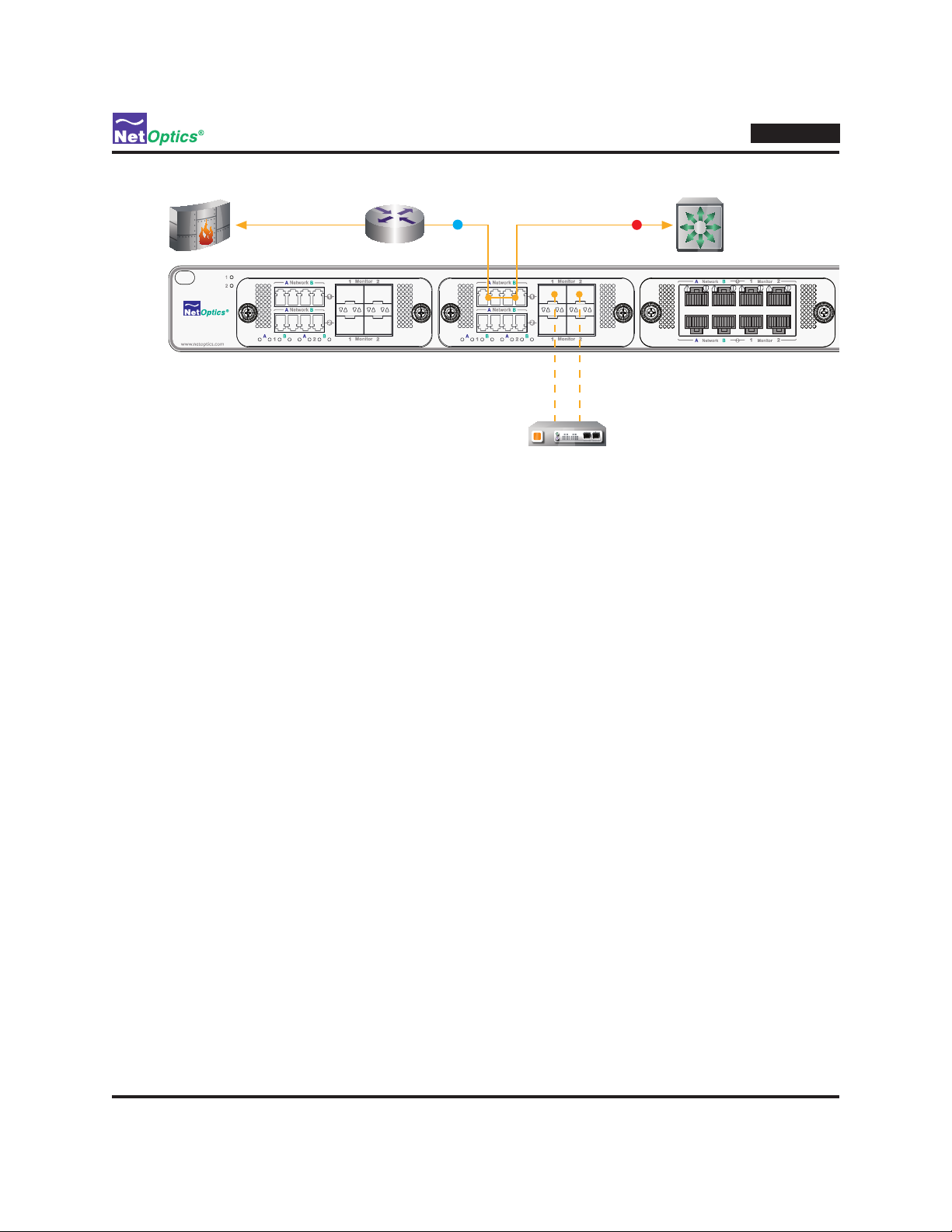
Congure Bypass Switch and DBM Options
Each bypass switch can be congured independently as a bypass switch or a Tap. To congure switch 1 as a bypass
switch, type segment set index=1 mode=sw. To congure switch 1 as a Tap, type segment set index=1 mode=tap.
The bypass switch modes are:
• Switch (sw) – Normal bypass switch operation
• Force Bypass On (bp_on) – Like switch mode, except the bypass switch is forced in Bypass On mode, in the
same state as if Bypass On had been entered because of lost Heartbeat packets
• Tap (tap) – The switch becomes a half-duplex breakout Tap, bridging network trafc between network port A
and network port B, while mirroring trafc entering network port A to monitor port 1 and trafc entering network
port B trafc to monitor port 2
IDS
Figure 17: Bypass switch 3 in Tap mode
iBypass HD
The following options can be congured for each DBM by using the module set command. The names used in the CLI
for the options are shown in parentheses.
• Administration (admin) – enable and power up or disable and power down the DBM
• High Availability Mode (ha_mode) – sets a pair of switches into a high availability (HA) mode; explained
further in a subsequent section starting on page 30
The syntax for the module set command is as follows. Bold indicates the default setting.
module set index=<1-4|all> [admin=<enable|disable>] [ha_mode=<link|tool|force|disable>] [primary_link=<1|2>]
[primary_tool=<1|2>]
For example, to disable and power down DBM 3, type module set index=3 admin=disable followed by commit.
28
Page 33

Customize Heartbeat Packets
You can dene a custom Heartbeat packet for each of the eight segments. The packet contents can be specied using
the heartbeat set command. In addition, the timeout, retries can also be changed.
A default Heartbeat packet is available for all segments. The default Heartbeat packet is:
00 50 c2 3c 60 00 (source address)
00 50 c2 3c 60 01 (destination address)
81 37 ff ff (packet type)
00 30 00 00
00 00 40 04
ec a2 c6 13
01 02 c6 13
01 01 00 00
00 00 00 00 (payload bytes)
00 00 00 00
00 00 00 00
00 00 00 00
00 00 00 00
00 00 00 00
a0 07 37 99 (CRC)
To specify a custom Heartbeat packet, use the heartbeat set command. The syntax of the heartbeat set command is:
iBypass HD
heartbeat set index=<1-8> value=<hex string>
The argument value=, if present, must be the last argument in the command, enabling the <hex string> to have
embedded spaces.
The following example shows the Heartbeat packet for the rst DBM being set to the same value as the default packet.
If you customize a Heartbeat packet and subsequently want to return to the default packet, type this command.
Net Optics> heartbeat set index=1 value=00 50 c2 3c 60 00 00 50 c2 3c 60 01
81 37 ff ff 00 30 00 00 00 00 40 04 ec a2 c6 13 01 01 00 00 00 00 00 00
00 00 00 00 00 00 00 00 00 00 00 00 00 00 00 00 00 00 00 00 00 00 00 00
a0 07 37 99
Net Optics>
If you enter a Heartbeat packet with less than the minimum Ethernet packet size of 64 bytes, it is automatically padded
with zeros to 64 bytes. The maximum size allowed for the Heartbeat packet is 128 bytes. Be sure to include valid CRC
bytes for your packet.
The use of spaces in the value eld is optional and can be used for readability. The value cannot contain newline
characters. (In the example, the command is one long line that wraps on the screen.)
To see the settings of the custom Heartbeat packets, type heartbeat show.
The heartbeat set command accepts three additional optional arguments (not shown in the systax denition on
the previous page: These arguments are: mode=<port1|port2|both||disable> retries=<1..10> interval=<1..65535>
timeout=<1..65535>
29
Page 34

• Heartbeat Mode (mode) – selects whether Heartbeat Packets should be issued from monitor port 1, 2, or both
• Heartbeat Retry Count (retries) – number of times in a row that the Heartbeat packets are missed in order to
trigger Bypass On state; for example, when retries=1, Bypass On is triggered when a single Heartbeat packet is
lost; the value must be in the range of 1 to 10; the default value is 1
• Heartbeat Interval (interval) – number of milliseconds between emitting Heartbeat packets; the value must be
in the range of 1 to 65535; values greater than or equal to 1000 (1 second) are recommended for 1 Gbps bypass
switches; the default value is 1000
• Heartbeat Timeout (timeout) – number of milliseconds to wait for a Heartbeat packet to be returned, before
it is determined to be lost; the value must be in the range of 1 to 65535 and must be less than or equal to the
Heartbeat Interval; the default value is 1000
Use Bypass Switch Pairs in High Availability (HA) Mode
The pair of bypass switches in each DBM can be congured to operate in a HA mode that supports both redundant links
and redundant tools. If you want to operate with both redundant links and redundant tools, choose ha_mode=both.
If you want to operate with redundant links and a single tool, choose ha_mode=link and only the tool set as
primary_tool=<1|2> will be used. To operate with redundant tools and a single link, choose ha_mode=tool and only
the link set as primary_link=<1|2> will be used. Set ha_mode=disable to use the two segments independently, not in
an HA mode.
The following sections describe HA operation when the primary link and primary IPS are active, when the primary link
fails, when the primary IPS fails, and when both the primary link and the primary IPS fails.
HA mode—Normal operation
HA mode enables two links and two IPSs to be connected to a DBM, with the second link and IPS acting as backups for the
primary link and IPS. Normal operation, when both links and both tools are functional, is shown in the following gure:
iBypass HD
Active link
IPS
Normal Operation
Internet
Passive link
Figure 18: DBM 1 operating in HA mode
At the top of Figure 18, trafc is shown owing on the upper link (segment 1) from the Internet, through bypass switch 1
(the primary bypass switch) and IPS, to the router. (It also ows in the opposite direction.) The lower link (segment 2) is a
backup in case the active link fails; the lower link's path through the bypass switch is in Bypass On mode, so trafc can
ow on the link if there is any trafc moving through the backup path.
A second IPS is installed on the monitor ports of bypass switch 2, to act as a backup in case the primary IPS fails.
Heartbeat packets are sent through the backup IPS because bypass switch 2 is in Bypass On mode.
Backup IPS
30
Page 35

iBypass HD
X
Active link
Passive link
Internet
IPS
Backup IPS
Normal Operation
Passive link
Active link
Internet
X
IPS
Active link
Passive link
Internet
IPS
Backup IPS
Backup IPS
Normal Operation
Operation When Primary Link Fails
HA mode—Link failure
In Figure 19, the active router failed and its link to the iBypass Switch went down. The bypass switch reacted to the link
down condition by entering Bypass On mode on the primary link and routing the trafc on the backup link through the
IPS. This action occurred automatically, without any manual intervention by the system administrator. The iBypass Switch
continues to mointor the primary link, and if the down link comes back up (that is, then both sides of the primary link are
connected), the IPS is moved back to the primary link and the backup link goes into Bypass On mode again.
Passive link
IPS
Operation When Primary Link Fails
Internet
Active link
Figure 19: HA mode with a link failure
In some cases, the primary link might fail in a way that doesn't actually lose link. For example, it could fall victim to
a Denial of Service attack, or it could experience a major slowdown for some reason. In usch a case, an administator
or a management tool could switch to using the backup link. In such circumstances, the bypass switch can be forced to
move to the backup link by setting the DBM HA mode force (ha_mode=force) and assigning the link you want as the
primary_link and the tool you want as the primary_tool.
HA mode—IPS failure
In Figure 20, the primary IPS stopped passing Heartbeat packets so the bypass switch rerouted the trafc through the
backup IPS. This action occurred automatically, without any manual intervention by the system administrator. The
bypass switch continues to send Heartbeat packets to the failed IPS, and when it comes back online, the bypass switch
automatically changes the trafc routing so it goes through the primary IPS again.
If both IPSs fail to respond to Heartbeat packets, both bypass switches go into Bypass On mode, opening both links to
trafc ow without going through either IPS.
Active link
Backup IPS
IPS
X
Operation When Primary IPS Fails
Internet
Figure 20: HA mode with an IPS failure
Passive link
Backup IPS
31
Page 36

Passive link
Active link
Internet
X
IPS
Active link
Active link
Passive link
Internet
IPS
Backup IPS
Backup IPS
Normal Operation
Operation When Primary Link Fails
Backup IPS
IPS
X
Operation When Primary IPS Fails
Passive link
Internet
X
iBypass HD
While in HA mode, the administrator can manually take an IPS ofine for maintenance or other purposes by setting the
DBM HA mode to force (ha_mode=force) and assigning the link you want to be active as the primary_link and the
tool you want to be active as the primary_tool. The other tool is ofine and can be removed from the system. Simply
unplugging one of the cables connecting the iByass Switch to the IPS, or powering off the IPS, accomplishes the same
thing.
HA mode—IPS and Link failure
Figure 21 shows what happens when both the primary link and the primary IPS fail or are taken down by the
administrator. Trafc on the bottom link becomes the active trafc, and the backup IPS is switched into the data path.
Bypass switch 1 is in Bypass On mode on both its link and tool sides, and bypass switch 2 is in Bypass Off mode on its
link and tool sides. When the uppper link is restored to service, its trafc will once again become active, and when the
primary IPS is restored to service, trafc will be routed through it instead to the backup IPS once again.
Passive link
IPS
X
Operation When Primary Link
and Primary IPS Fail
Internet
Active link
Figure 21: HA mode with a link failure AND an IPS failure
Entering HA mode
To place a pair of bypass switches into an HA mode, use the module set index=<n> ha_mode=<link|tool|both>
command, where <n> is the number of the DBM (1..4). To designate one of the links as the primary of the pair, include
the argument primary_link=<1|2>. If a primary is not designated, the link attached to the top set of ports is the primary.
To designate one of the IPSs as the primary of the pair, include the argument primary_tool=<1|2>. If a primary is not
designated, the IPS attached to the top set of ports is the primary.
A typical command sequence is:
To set DBM 2 into HA mode with link and tool redundancy, with the top link and bottom tool as primary:
Net Optics> module set index=2 ha_mode=both primary_tool=2
To force the bottom link to be used (removing link redundancy):
Net Optics> module set index=2 ha_mode=force primary_link=2
To enable link redundancy again, but now the bottom link is primary (as set in the previous command):
Net Optics> module set index=2 ha_mode=both
To change the top tool to be the primary, while maintining link and tool redundancy:
Net Optics> module set index=2 primary_tool=1
To force the bottom tool to be used (removing tool redundancy) – the top tool becomes free for servicing:
Net Optics> module set index=2 ha_mode=force primary_tool=2
To leave HA mode and use the two segments independently:
Net Optics> module set index=2 ha_mode=disable
Backup IPS
32
Page 37

Conguring AAA Servers
The iBypass HD can access RADIUS and TACACS+ servers to perform user authentication and authorization.
(Athentication and authorization, along with accounting, are referred to as AAA services.)
In this chapter, you will learn to:
• Congure the iBypass HD to access RADIUS and TACACS+ AAA services
Congure RADIUS and TACACS+ Servers
The iBypass HD can be congured to obtain AAA services from 0 to 3 RADIUS servers and 0 to 3 TACACS+ servers,
in addition to its local (internal) user account list. When a user attempts to log into the system, the iBypass HD always
checks its local accounts rst. It then queries all congured AAA (RADIUS and TACACS+) servers in the sequence
you specify, until authentication is successful. If authentication is unsuccessful locally and on all congured servers, the
login request is denied.
You can congure from 1 to 3 RADIUS servers plus 1 to 3 TACACS+ servers using multiple server add commands.
Each time you add an AAA server, it is added to the end of the AAA server list (which includes both RADIUS and
TACACS+ servers), making it the last server that will be queried. You can add the server in a different position in the
list by specifying an ID when you add it; for example, id=1 places the server at the head of the list, making it the rst
server that will be queried.
iBypass HD
Chapter 5
Mapping privilege levels
When you add an AAA server, the priv_map argument denes how the privilege level returned by the AAA server is
mapped to the three privilege levels supported by the iBypass HD. The priv_map argument takes a list of three values.
The rst value (a or v) determines whether lower numbers map to the admin privilege level (a) or the view privilege
level (v). The user level is always in the middle. The second value species the lowest returned privilege level that
maps into the user level, and the third value species the highest returned privilege level that maps into the user level.
AAA Privilege Level the iBypass HD Privilege
Level
priv_map=a,2,2
Figure 22: Privilege level mapping showing the default mapping
5
4
3
2
1
0
view
user
admin
33
Page 38

iBypass HD
AAA Privilege Level the iBypass HD Privi-
lege Level
priv_map=v,5,9
Figure 23: Privilege level mapping with lower numbers as View level
12
11
10
9
8
7
6
5
4
3
2
1
admin
user
view
If the AAA server does not return an authorization privilege level, the iBypass HD privilege level defaults to view. You
can change the default privilege level on a per server basis with the priv_default argument, setting it to 1 for admin, 2
for user, and 3 for view.
Using AAA server commands
RADIUS and TACACS+ servers are congured using the same commands. The only difference is the argument type,
which is set to rad for a RADIUS server and tac for a TACACS+ server.
To add an AAA server:
1. Type server add type=<rad|tac> admin=enable srvip=120.30.10.1 pw=rad_password priv_map=v,5,9,
replacing the argument values with ones appropriate for your system environment.
The server conguration is made pending.
2. Type server show.
Verify that the server conguration is correct. Note the ID of the server if you want to modify any of its parameters.
(If this is the rst AAA server congured, its ID will be 1.)
3. If you want to modify any of the server parameters, use the server mod command.
For example, to change the IP address, type server mod type=<rad|tac> id=1 srvip=120.30.20.2. (An error
message is displayed if the type of server specied does not match the type of the server at that id.)
4. Type server commit.
The server conguration is activated.
34
Page 39

iBypass HD
To add an AAA server at the beginning of the AAA services query sequence:
1. Type server add id=1 type=<rad|tac> admin=enable srvip=120.30.10.3 pw=rad_password priv_map=v,5,9,
replacing the argument values with ones appropriate for your system environment.
The server conguration is made pending.
2. Type server commit.
The server conguration is activated.
To disable an AAA server while leaving its conguration in the system:
3. Type server show.
Note the ID of the server you want to disable.
4. Type server mod id=<id> type=<rad|tac> admin=disable replacing <id> with the ID you noted in Step 1.
Disabling of the server is made pending.
5. Type server commit.
The server is disabled. To re-enable the server, type server mod id=<id> type=rad admin=enable.
To delete an AAA server from the conguration:
1. Type server show. Note the ID of the server you want to delete.
2. Type server del id=<id> type=<rad|tac> replacing <id> with the ID you noted in Step 1.
Deletion of the server is made pending.
3. Type server commit.
The server is deleted from the conguration.
35
Page 40

Conguring AAA servers
Below are examples for conguring RADIUS and TACACS+ servers.
To set the privilege level to 2 for the user account raduser on an Open RADIUS server:
1. Locate the RADIUS conguration le /usr/local/etc/raddb/users.
2. Add the line Class = 2 to the le for user account raduser.
After editing, the raduser account in the le should look similar to this:
raduser
Cleartext-Password := "raduser"
Service-Type = Framed-User,
Framed-Protocol = PPP,
Class = 2,
Framed-IP-Address = 172.16.3.33,
Framed-IP-Netmask = 255.255.255.0,
Framed-Routing = Broadcast-Listen,
Framed-Map-Id = "std.ppp",
Framed-MTU = 1500,
Framed-Compression = Van-Jacobsen-TCP-IP
To set the privilege level to 1 for the user account tacuser on a TACACS+ (tacacs+-F4.0.4.18) server:
1. Locate the TACACS+ conguration le tac_plus.conf.
iBypass HD
2. Add the line Priv-Lvl = 1 to the le for user account tacuser.
After editing, the tacuser account in the le should look similar to this:
key = netoptics
user = tacuser {
login = cleartext tacuser
service = ppp protocol = ip {
priv-lvl = 1
}
}
36
Page 41

Specications
Mechanical
Dimensions: 1.75” high x 19” wide x 27" deep
Mounting: Surface or 19” rack mount (1U)
Weight: 8.2 lbs (3.7 kg)
Connectors
Network Ports: (16) RJ45 (copper) or 16 Duplex LC (ber)
Monitor Ports: (16) RJ45 (copper) or 16 SFP (ber)
Management Ports: (1) RJ45 RS232 and (1) RJ45 10/100/1000 copper network
Power: (2) AC universal or (2) -48VDC, redundant, hot-swappable
Electrical Interface
AC Input: 100-240 VAC, 47-63 Hz, 1.45 A max @ 115 VAC,
0.75 A max @ 230 VAC
DC Input: -48 VDC nominal -36 to -72 VDC, 5.4 A max @ 36 VDC,
2.7 A max @ 72 VDC
DC Receptacle: Terminal peak, 12-14 gauge wire
Indicators
(All ports) Link LEDs, speed indication on 10/100/1000 ports
(All ports) Activity LEDs
(2) Power LEDs
Performance
Hardware throughput: 8Gbps
RMON statistics for each network and monitor port: Current utilization, total bytes, total packets, jumbo packets,
CRC errors
Authentication and Authorization
RADIUS and TACACS+ supported (6 servers total)
Software
Command line interace (CLI), RS232 local or SSH remote, RADIUS, TACACS+, RMON trafc statistics
iBypass HD
Appendix A
iBypass HD Specications
Environmental
Operating Temperature: 0˚C to 40˚C
Storage Temperature: -10˚C to 70˚C
Relative Humidity: 10% min, 95% max, non-condensing
Certications
FCC, CE, FCC, VCCI, and C-Tick certied
Fully RoHS and WEEE compliant
Fully 802.3 compliant
37
Page 42

Available Models
IBP-8000 iBypass HD, Main Chassis, 4 DBM Bays
IBP-8000-DC iBypass HD, Main Chassis, 4 DBM Bays, DC Power
DBM-100 DBM, iBypass HD, 10/100/1000, RJ45
DBM-200 DBM, iBypass HD, Gig, MM, 62.5um, SFP Monitor Ports
DBM-250 DBM, iBypass HD, Gig, MM, 50um, SFP Monitor Ports
DBM-300 DBM, iBypass HD, Gig, SM, 8.5um, SFP Monitor Ports
iBypass HD
38
Page 43

iBypass HD
Appendix B
Command Line Interface
The CLI is case-sensitive; commands must be entered in lower case. However, certain items such as user-dened text
strings, user names, and passwords can be entered in upper, lower, or mixed case, and are also case-sensitive.
The tab key or the space key can be used to automatically complete words in the CLI. This function works for commands
as well as arguments. For example, typing the letter "t" followed by the tab key results in "time" being entered in the
command line. Likewise, "he<tab>" auto-completes to the "help" command. However, "h<tab>" does not auto-complete,
because it is ambiguous between the "help" and "history" commands.
To display a list of sub-commands and arguments for any command, press the ? key after entering the command. (A
space is required between the command and the ?.) For example, type "switch ?" to display a list of all the arguments
that can be used to complete the command.
Module, switch, and port identication
When the CLI needs to identify a bypass switch or port, the following syntax is used.
• The eight bypass switches are identied as sw1, sw2, ... sw8, from left to right across the chassis; sw1 and sw2
are in Dual Bypass Module (DBM) 1, sw3 and sw4 are in DBM 2, sw5 and sw6 are in DBM 3, and sw7 and
sw8 are in DBM 4
• An swlist is a list of switches separated by commas; a range can be indicated with a dash; space characters are
not allowed in the list (do not put a space after the comma or around a dash); for example, sw1-sw3,sw7
• Within each bypass switch, the network ports are indentied as a or A (on the left) and b or B (on the right); the
monitor ports are 1 (on the left) and 2 (on the right)
• A particular port is specied by concatinating its switch and port with a dot delimiter, for example, sw1.a
• A portlist is a list of switches and ports separated by commas; space characters are not allowed in the list (do not
put a space after the comma); if a switch is listed without specifying a port, then all four of the switch's ports
are included in the list; for example, sw1.a,sw1.b,sw3.2,sw6 is a list of seven ports
Privilege levels
User accounts are assigned one of three privilege levels:
• admin (level 1) – access to all CLI commands; only the admin level can use the user,passwd, heartbeat set,
module set, port set, segment set, security, and server commands
• user (level 2) – access to all CLI commands except those listed above for admin level
• view (level 3) – can access only these CLI read-only commands: cong list, cong show, help, history, ping,
exit, logout, and quit
All accounts are authorized to use the user mod command to change their own passwords.
For complete information about the iBypass HD CLI, see the iBypass HD CLI Command Reference manual.
39
Page 44

iBypass HD
iBypass HD CLI Quick Reference
Table key
The table uses alternate row shading to distiguish commands and subcommands, as indiated in the following example.
Command Sub-Command Arguments Example
command1 subcommand1
for command1
command2 subcommand1
for command2
subcommand2
for command2
subcommand3
for command2
command3 subcommand1
for command3
subcommand2
for command3
arguments for
subcommand1
arguments for
subcommand1
arguments for
subcommand2
arguments for
subcommand3
arguments for
subcommand1
arguments for
subcommand2
an example of how to use command1 subcommand1
an example of how to use command2 subcommand1
an example of how to use command2 subcommand2
an example of how to use command2 subcommand3
an example of how to use command3 subcommand1
an example of how to use command3 subcommand2
Table of CLI Commands
Command Sub-Command Arguments Example
! <number> Net Optics> !3
commit [force=<all | dbmlist>] Net Optics> commit
cong del le=<name> Net Optics> cong del le=my_conguration-1
list Net Optics> cong list
load le=factory|<name> Net Optics> cong load le=my_conguration-1
save le=<name> Net Optics> cong save le=my_conguration-1
show le=running|factory|<name> Net Optics> cong show le=running
date [<date>] Net Optics> date 04/11/2010
exit Net Optics> exit
40
Page 45

Command Sub-Command Arguments Example
heartbeat commit Net Optics> heartbeat commit
reset index=<1..8|seglist|all> Net Optics> heartbeat reset index=1-4,7
set index=<1..8|seglist|all>
[mode=<port1|port2|both|
disable>]
[retries=<1..10>]
[interval=<1..65535>]
Net Optics> heartbeat set index=2 mode=port1
value=00 50 c2 3c 60 00 00 50 c2 3c 60 01 81 37 ff
ff 00 30 00 00 00 00 40 04 ec a2 c6 13 01 01 00 00
00 00 00 00 00 00 00 00 00 00 00 00 00 00 00 00
00 00 00 00 00 00 00 00 00 00 00 00 a0 07 37 99
[hb_gen_crc=<on|off>]
[hb_in_tap=<on|off>]
Note: value=<hex string> must be the nal argument
[oem=<disable>]
[value=<hex string>]
show [index=<seglist|all>]
Net Optics> heartbeat show
[content=<pending|running>]
help [<command>] Net Optics> help switch
history Net Optics> history
clear Net Optics> history clear
image <1|2> Net Optics> image 2
show Net Optics> image show
iBypass HD
logout Net Optics> logout
module commit [force=<1..4|dbmlist|all>] Net Optics> module commit
set index=<1..4|dbmlist|all>
[admin=<enable|disable>]
Net Optics> module set index=3
admin=enable ha_mode=disable crc_fwd=enable
[ha_mode=<link|[tool|
both|force|disable>]
[primary_link=<1|2>]
[primary_tool=<1|2>]
[crc_fwd=<enable|disable>]
[psize=60..10240>]
show Net Optics> module show
passwd Net Optics> passwd
ping <address> Net Optics> ping 10.1.1.4
41
Page 46

Command Sub-Command Arguments Example
port clear ports=<s1..s8|seglist|all> Net Optics> port clear ports=s8
set ports=<s1..s8|seglist|all>
Net Optics> port set ports=s3,s4 autoneg=on
[admin=<enable|disable>]
[autoneg=<on|off>]
Note that ports= takes a segment list, not a port list
[content=<cfg|stats>]
[duplex=<full|half>]
[speed=<10|100|1000>]
show ports=<s1..s8|seglist|all>
Net Optics> port show seg=all
content=<cfg|stats>
quit Net Optics> quit
security gen-ssh type=<ssh-rsa> key-
length=<768|1024|2048>
show type=<ssh-rsa>
segment commit [force=<1..4|dbmlist|all>]
set index=<1..8|seglist|all>
Net Optics> segment set index=3,4 mode=tap
[mode=<sw | bp_on | tap>]
[bp_on_trafc=<on|off>]
[bp_detect=<on|off>]
[fail_state=<fail_to_wire|no_trafc>]
[lfd=<on|off>]
show [content=<pending|running|
Net Optics> segment show content=running
status|all>]
server add type=<rad|tac>
[id=<id>]
Net Optics> server add type=rad admin=enable
srvip=120.30.10.1 pw=rad_password priv_map=v,5,9
[admin=enable|disable]
[srvip=<address|domain>]
[port=<number>]
pw=<password>
[timeout=<1..10>]
[retries=<1..10>]
[priv_map=
<a|v,lower,upper>]
[priv_default=<1|2|3>]
commit Net Optics> server commit
del type=<rad|tac>
Net Optics> server del type=tac id=1
[id=<id>]
mod type=<rad|tac>
Net Optics> server mod type=rad id=3 id_new=5
[id_new=<id>]
The rest of the arguments
are the same as for server
add
show Net Optics> server show
iBypass HD
42
Page 47

iBypass HD
Command Sub-Command Arguments Example
sysip commit Net Optics> sysip commit
discard Net Optics> sysip discard
set ipaddr=<address>
mask=<netmask>
Net Optics> sysip set ipaddr=100.6.4.15
mask=255.255.0.0 gw=10.0.0.1
gw=<gateway>
show Net Optics> sysip show
system prompt Net Optics> system prompt text=My prompt:
restart Net Optics> system restart
time [<time>] Net Optics> time 13:02:00
upgrade srvip=<srvip>
user=<username>
Net Optics> upgrade srvip=168.192.20.2 user=bob
pw=bobpw le=image021108
pw=<password>
le=<lename>
user add name=<username>
Net Optics> user add name=bob pw=bob-pw priv=3
pw=<password>
priv=<level>
del name=<username> Net Optics> user del name=bill
mod name=<username>
Net Optics> user mod name=bill pw=netbillpw priv=2
pw=<password>
priv=<level>
show Net Optics> user show
43
Page 48

iBypass HD
Limitations on Warranty and Liability
Net Optics offers a limited warranty for all its products. IN NO EVENT SHALL NET OPTICS, INC. BE LIABLE FOR ANY
DAMAGES INCURRED BY THE USE OF THE PRODUCTS (INCLUDING BOTH HARDWARE AND SOFTWARE)
DESCRIBED IN THIS MANUAL, OR BY ANY DEFECT OR INACCURACY IN THIS MANUAL ITSELF. THIS INCLUDES
BUT IS NOT LIMITED TO LOST PROFITS, LOST SAVINGS, AND ANY INCIDENTAL OR CONSEQUENTIAL DAMAGES
ARISING FROM THE USE OR INABILITY TO USE THIS PRODUCT, even if Net Optics has been advised of the possibility of
such damages. Some states do not allow the exclusion or limitation of implied warranties or liability for incidental or consequential
damages, so the above limitation or exclusion may not apply to you.
Net Optics, Inc. warrants this device to be in good working order for a period of ONE YEAR from the date of purchase from Net
Optics or an authorized Net Optics reseller.
Should the unit fail anytime during the said ONE YEAR period, Net Optics will, at its discretion, repair or replace the product. This
warranty is limited to defects in workmanship and materials and does not cover damage from accident, disaster, misuse, abuse or
unauthorized modications.
If you have a problem and require service, please call the number listed at the end of this section and speak with our technical
service personnel. They may provide you with an RMA number, which must accompany any returned product. Return the product
in its original shipping container (or equivalent) insured and with proof of purchase.
Additional Information
Net Optics, Inc. reserves the right to make changes in specications and other information contained in this document without prior
notice. Every effort has been made to ensure that the information in this document is accurate. Net Optics is not responsible for
typographical errors.
THE WARRANTY AND REMEDIES SET FORTH ABOVE ARE EXCLUSIVE AND IN LIEU OF ALL OTHERS, EXPRESS
OR IMPLIED. No Net Optics reseller, agent, or employee is authorized to make any modication, extension, or addition to this
warranty.
Net Optics is always open to any comments or suggestions you may have about its products and/or this manual.
Send correspondence to
Net Optics, Inc.
5303 Betsy Ross Drive
Santa Clara, CA 95054 USA
Telephone: +1 (408) 737-7777
Fax: +1 (408) 745-7719
E-mail: info@Net Optics.com / Internet: www.Net Optics.com
All Rights Reserved. Printed in the U.S.A. No part of this publication may be reproduced, transmitted, transcribed, stored in a
retrieval system, or translated into any language or computer language, in any form, by any means, without prior written consent
of Net Optics, Inc., with the following exceptions: Any person is authorized to store documentation on a single computer for
personal use only and that the documentation contains Net Optics’ copyright notice.
44
Page 49

www.netoptics.com
© 2008-2010 by Net Optics, Inc. All Rights Reserved.
 Loading...