

Page 1
Quick Install Guide
I2BP-40
800-0228-001 Rev A 12/13
Page 2

PLEASE READ THESE LEGAL NOTICES CAREFULLY.
By using the Net Optics iBypassTM 40G Switch, you agree to the terms and conditions of usage set forth by Net Optics,
Inc.
No licenses, express or implied, are granted with respect to any of the technology described in this manual. Net Optics
retains all intellectual property rights associated with the technology described in this manual. This manual is intended
to assist with installing Net Optics products into your network.
Trademarks and Copyrights
©2013 by Net Optics, Inc. Net Optics is a registered trademark of Net Optics, Inc. iBypass is a trademark of Net Optics,
Inc. Additional company and product names may be trademarks or registered trademarks of the individual companies
and are respectfully acknowledged.
Additional Information
Net Optics, Inc. reserves the right to make changes in specications and other information contained in this document
without prior notice. Every effort has been made to ensure that the information in this document is accurate.
2
Page 3

Contents
iBypass 40G Switch Content 4
iBypass 40G Switch Overview 5
Connect Power 8
Connect Options 10
Congure the IP 14
Assign IP in Web UI 16
Connect to the Network 18
Connect Monitoring Tools 19
3
Page 4

iBypass 40G Switch Content
This guide provides the initial steps to set up and congure the Net Optics iBypassTM
40G Switch.
Carefully unpack the contents and verify you have the following components:
• iBypass 40G Switch
• 3-meter RJ45, CAT 5e 4-pair
• RJ45 to DB9 Console Port to PC cable
• Long Ear Extender and Short Ear Extender for rack mounting
• Two External Power Supplies (12VDC, 9A, 108W)
• Eight Phillips screws
• iBypass 40G Switch Quick Install Guide (this document)
• iBypass 40G Switch User Guide (on CD)
• End User Agreement, Registration Card and Extended Warranty (if purchased)
The QSFP+ transceiver kits and 40G MTP cables are sold and shipped separately.
Contact Net Optics Technical Assurance Center if any component is missing or
damaged. Contact details are at the back of this guide.
4
Page 5
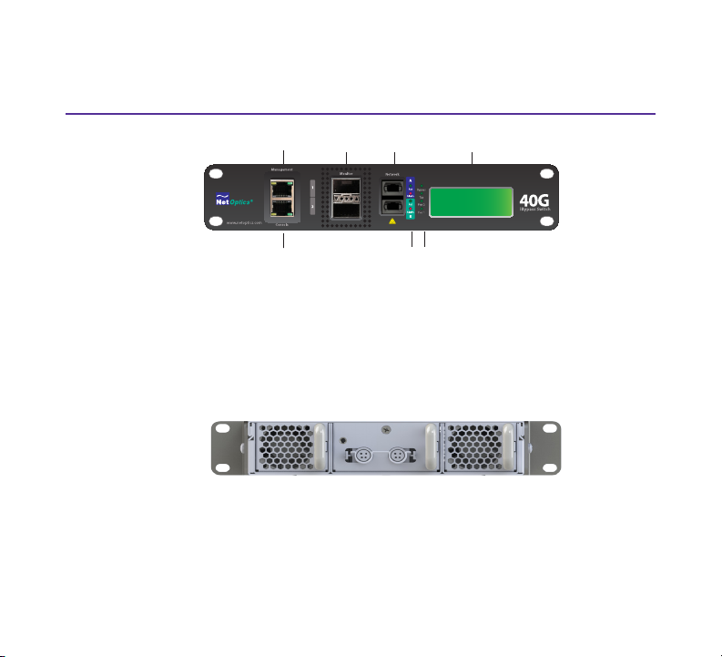
iBypass 40G Switch Overview
2x16 Character Display
Network
Ports
Monitor
Ports
Bypass, Tap, Power
LEDs
Activity & Alarm
LEDs
Management
Port
Console
Port
Figure 1 - Front View
• Console Port (RJ45) and Management Port (RJ45)
• 2 x 40G Monitor Ports (uses QSFP+ transceivers )
• 2 x 40G Network Ports (MTP Connectors)
Figure 2 - Rear View
• Hot swappable fans and replaceable power module
5
Page 6

Step 1
Rack Mount iBypass 40G Switch
Install the iBypass 40G Switch into a standard 19-inch equipment rack. The switch is
designed to occupy one rack unit. Do the following to install the iBypass 40G Switch
into an equipment rack:
1. Remove the Ear Extenders and screws from the shipping bag.
2. Attach the Long Ear Extender to the switch if you are only mounting one switch
or attach the Short Ear Extender between two switches if you are mounting two
switches. See Figure 3.
3. Slide the switches in place in the rack.
4. Fasten the switches in place at the front panel ears using the Phillips screws.
5. Make sure the rack is properly electrically grounded.
Grounding
Ground the chassis to the rack by connecting a 14 AWG minimum ground wire with a
#8 ring lug to the ground connection on the rear of the chassis. Terminate the other
end of the ground wire to the rack ground bus bar.
6
Page 7

Long Ear Extender
for one switch
Short Ear Extender
binds two switches
Figure 3 - Use Ear Extenders in Rack Mount Preparation
7
Page 8

Step 2
Connect Power
Ensure the iBypass 40G Switch is grounded before connecting power. Do the
following to connect and apply power to the iBypass 40G Switch:
1. Plug one of the supplied power cords to a power connector located at the rear
of the chassis. Plug the other end to a power source. See Figure 4.
2. For redundancy, plug the other power cord to the iBypass 40G. Plug the other
end to a source independent from the rst power source.
The Power LEDs on the front illuminate.
Switch Default Settings
The iBypass 40G Switch ships with the following default system settings:
Management Port IP: 10.60.4.180 Threshold Ports A & 1: 80%
Management Port Netmask: 255.0.0.0 Threshold Port B & 2: 80%
Management Port Gateway: 10.0.0.1 Username: admin
Port Speed (A, B, 1, and 2): 40G Password: netoptics
8
Page 9
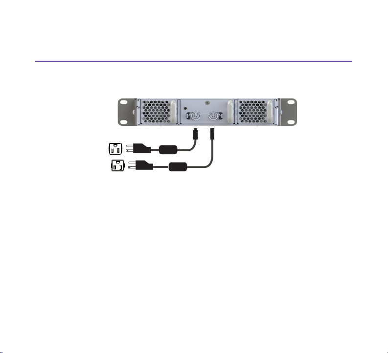
Figure 4 - Power Connections
9
Page 10

Step 3
Connect Options
You have two ways of logging in to the iBypass 40G switch.
Option 1 - Connect PC to Management Port
1. Connect a PC whose IP address is on the same subnet as the iBypass switch.
The default address on the switch is:
IP Address: 10.60.4.180 Mask - 255.0.0.0 Gateway - 10.0.0.1
2. Connect a Cat 5e cable from your PC’s Ethernet port to the iBypass
Management port. See Figure 5.
3. Open a terminal window and ping 10.60.4.180 to conrm the connection.
4. After you have conrmed that you have a connection, you can log in via SSH at
the terminal prompt, or enter the default address into the browser URL. Go to
the Assign IP in Web UI section if you want to log in through the Web UI. Go
to the next step if you want to log in to the CLI.
5. At the terminal window prompt, type ssh admin@10.60.4.180. Enter
password netoptics. The Net Optics prompt appears.
6. At the prompt, enter admin for the user and netoptics for the password.
7. Change the password for the admin account by entering the following
command at the prompt:
modify user password admin <new_passwd> <re-enter_passwd>
where <new_passwd> is the new password for the admin account and
<re-enter_passwd> is your password entered again.
10
Page 11

8. Go to Congure the IP section and follow the instructions to set a new IP
PC on the same subnet
as iBypass 40G switch
Connect Cat 5e cable from
Management port to PC
Ethernet
address.
For more information about using the iBypass 40G Switch CLI, enter help to display
command information or see the iBypass 40G Switch User Guide for more details.
Figure 5 - PC to Console Port
11
Page 12

Step 3 (cont.)
Option 2 - Connect PC to the Console Port
1. Connect a PC running terminal emulation software to the iBypass 40G Switch
Console port with the supplied DB9-RJ45 console cable. See Figure 6.
2. Launch the terminal emulation software, such as HyperTerminal or minicom,
and set the communication parameters to 115,200 baud, 8 data bits, no parity,
1 stop bit, and no ow control.
3. At the prompt, enter admin for the user and netoptics for the password.
4. Change the password for the admin account by entering the following
command at the prompt:
modify user password admin <new_passwd> <re-enter_passwd>
where <new_passwd> is the new password for the admin account and
<re-enter_passwd> is your password entered again.
5. Go to Congure the IP section and follow the instructions to set a new IP
address.
For more information about using the iBypass 40G Switch CLI, enter help to display
command information or see the iBypass 40G Switch User Guide for more details.
12
Page 13

Computer with terminal
emulation software
DB9 to RJ45 console
cable
Figure 6 - PC to Console Port
13
Page 14

Step 4
Congure the IP
The iBypass 40G switch ships with a default address. You can decide to use the
default address, assign a static IPv4 or IPv6 IP address or use DHCP to assign an
address.
To congure the system with a static IPv4 or IPv6 address, do the following:
1. At the CLI prompt, type the following to set the address mode to static:
set network mode static
2. Type the following to set the IPv4 address:
set network ipaddress <d.d.d.d> where <d.d.d.d> is the IPv4 address
3. Type the following to set the network mask:
set network netmask <m.m.m.m> where <m.m.m.m> is the netmask.
4. Type the following to set the gateway:
set network gateway <g.g.g.g> where <g.g.g.g> is the gateway address.
5. Type reboot host, to reboot the system. This is required for the new address to
take effect. The new IP address will display in the LCD.
After setting the IP address, connect the Management port to the network, so
that you can access the device remotely over SSH or launch the Web UI with
the new IP address.
14
Page 15

Do the following to congure the system to use a DHCP address:
1. At the CLI prompt, type set network mode dhcp.
2. At the next prompt, type reboot host
3. After reboot, log into the iBypass via the PC connected to the Console port.
4. At the CLI prompt, enter show network. The screen will display the address
that was assigned to the switch.
15
Page 16

Assign IP in Web UI
If you want to change the IP address through the Web UI, do the following:
1. Open a browser on a PC connected to the iBypass switch or on the same
subnet, and enter the default IP address in the URL, https://10.60.4.180.
2. At the iBypass log in banner page, enter Username admin and Password
netoptics. The Home page displays. See Figure 7.
3. At the Home page, click on the Conguration tab. The Conguration page
displays. See Figure 8.
4. Select IP version, select Static or DHCP.
5. If you select Static, enter the IP address, netmask, and gateway.
6. Click the Apply button.
7. Click Reboot.
8. After the iBypass has rebooted, enter the new IP address at the URL.
9. Re-log in. The iBypass home page displays.
16
Page 17

Figure 7 - Home Page
Figure 9 - Congure IP Web Page
17
Page 18

Step 5
Connect to the Network
The iBypass 40G Switch Network ports require 40G MTP cables.
Network port A to a
network switch or
router
Network port B to
a network switch
or router
Figure 10 - MTP Cables to the Network
1. Connect Network Port A to a network device with a 40G MTP cable.
2. Connect Network Port B to another network device using another 40G MTP
cable.
3. Verify that the Network ports are cabled in-line between two network devices.
4. Verify the link status LED illuminates for each connected port.
5. Verify the ACT LED ashes when there is trafc on the network link.
18
Page 19

Step 6
Connect Monitoring Tools
Do the following to connect monitoring tools to the iBypass 40G Switch:
Insert transceiver to
Monitor port 1
Insert transceiver to
Monitor port 2
Figure 11 - QSFP Connections to the Monitoring Tools
1. Insert QSFP+ transceivers into Monitor port 1 and Monitor port 2.
2. Connect a cable to Monitor port 1 transceiver and connect the other end to a
monitoring tool.
3. Connect a cable to Monitor port 2 transceiver and connect the other end to
another monitoring tool.
4. Verify that the monitoring tools are receiving trafc from the iBypass 40G
Switch.
19
Page 20

www.netoptics.com
If you have questions while your product is under warranty or you are enrolled
in a support plan, please contact the Net Optics Technical Assurance Center
(TAC) via email at support@netoptics.com or by calling +1.408.737.7777,
Monday through Friday, between the following hours in your region:
• 7:00 - 17:30 Americas (Pacic Time)
• 9:00 - 17:00 EMEA (Frankfurt Time)
• 9:00 - 17:00 APAC (Hong Kong Time)
You can also nd more information on our website at www.netoptics.com.
20
 Loading...