

Net Optics iBypass, IBPO-HBSR-XFP, IBPO-HBLR-XFP, IBPO-HB50SR-XFP, IBPO-HBER-XFP User Manual
...Page 1

User Guide
iBypass Switches with Heartbeat
™
800-0182-001 Doc. PUBIBPOHBU Rev. B 6/11
Page 2

PLEASE READ THESE LEGAL NOTICES CAREFULLY.
By using a Net Optics iBypass Switch you agree to the terms and conditions of usage set forth by
Net Optics, Inc.
No licenses, express or implied, are granted with respect to any of the technology described in this
manual. Net Optics retains all intellectual property rights associated with the technology described in this
manual. This manual is intended to assist with installing Net Optics products into your network.
Trademarks and Copyrights
© 2011 by Net Optics, Inc. Net Optics® is a registered trademark of Net Optics, Inc. iBypassTM is a
trademark of Net Optics, Inc. Additional company and product names may be trademarks or registered
trademarks of the individual companies and are respectfully acknowledged.
Additional Information
Net Optics, Inc. reserves the right to make changes in specications and other information contained
in this document without prior notice. Every effort has been made to ensure that the information in this
document is accurate.
Page 3

iBypass Switches with Heartbeat
iii
Contents
Chapter 1
Introduction ..................................1
About this Guide ....................................................1
Features ...........................................................1
Bypass Modes ......................................................3
Tap Mode During Bypass .............................................5
SNMP Traps .......................................................6
Trafc Statistics ....................................................6
Chapter 2
Front Panel ...................................7
Threshold Alarm LEDs ...............................................8
Link LEDs .........................................................8
Power LEDs .......................................................8
Reset Button .......................................................8
Chapter 3
Installing the iBypass Switch .....................9
Plan the Installation ..................................................9
Unpack and Inspect the iBypass Switch .................................10
Installing XFP or SFP Monitor Port Transceivers .........................10
Rack Mount the iBypass Switch (optional) ..............................10
Connect Power to the iBypass Switch ..................................11
Connecting to the CLI Interface .......................................12
Congure the iBypass Switch with the CLI ..............................13
Connect the iBypass Switch to the Network ..............................17
Connect the Management Port to the Network ............................17
Connect a Monitoring Device to the iBypass Switch .......................18
Check the Installation ...............................................19
Page 4

iBypass Switches with Heartbeat
iv
Chapter 4
Web Manager ................................20
Access Web Manager ...............................................20
Set Date and Time Window ..........................................24
Check/Change the Heartbeat Packet from Web Manager ....................25
Download and Install New Software ...................................26
Set Port Parameters .................................................28
Chapter 5
System Manager ..............................29
Overview .........................................................29
Install System Manager ..............................................30
Explore System Manager ............................................31
Create a System Manager Group ......................................33
Delete a System Manager Group ......................................33
Add Devices to a System Manager Group ...............................34
Delete an iBypass Switch from System Manager ..........................35
Congure an iBypass Switch from System Manager .......................36
View iBypass Switch Information from System Manager ...................39
Modify an iBypass Switch Name or Address from System Manager ..........42
Change a Heartbeat Packet from System Manager .........................42
Uninstalling System Manager .........................................43
Appendix A
Specications and Models ......................44
Specications .....................................................44
Available Models ..................................................46
Appendix B
Command Line Interface .......................47
iBypass Switch CLI Syntax ..........................................47
Set Parameter Port Command .........................................50
Page 5

iBypass Switches with Heartbeat
1
Chapter 1
Introduction
Thank you for choosing Net Optics 10 GigaBit Fiber, GigaBit Fiber, or 10/100/1000
iBypass Switch, the most versatile intelligent iBypass Switches available today. This
guide is designed to help answer your questions and provide an installation reference.
Net Optics iBypass Switch with Heartbeat provides a permanent access port for inline network security and monitoring. The iBypass Switch automatically switches
network trafc through added devices, or bypasses devices that are removed. The
intelligent iBypass Switch Heartbeat provides notications to protect network
trafc against both signal and power loss on an attached device.
About this Guide
This guide describes the installation and use of the following models:
Part Number Description
IBPO-HBSR-XFP 10 GigaBit SR iBypass Switch with Heartbeat
IBPO-HBLR-XFP 10 GigaBit LR iBypass Switch with Heartbeat
IBPO-HB50SR-XFP 10 GigaBit SR iBypass Switch with Heartbeat, 50um
IBPO-HBER-XFP 10 GigaBit ER iBypass Switch with Heartbeat
IBPO-HBLX-SFP GigaBit LX iBypass Switch with Heartbeat
IBPO-HBSX-SFP GigaBit SX iBypass Swith with Heartbeat
IBP-HBCU3 10/100/1000 iBypass Switch with Heartbeat
Features
Heartbeat Packet
The iBypass Switch monitors the attached device by sending a Heartbeat packet
to the device. If the iBypass Switch does not receive the Heartbeat response, it
automatically switches network trafc to bypass the unresponsive device—even
if the device is still receiving power. The iBypass continues to send the Heartbeat,
and will restore trafc ow through the device as soon as the link is restored .For
special applications, you can customize the Heartbeat Packet rate from the iBypass
Command Line Interface (CLI) or Web Manager GUI.
Page 6

iBypass Switches with Heartbeat
2
Uninterrupted Trafc
This iBypass Switch supports fail-open monitoring with any 10 GigaBit device
when it shares the same power source as the device. As long as the iBypass Switch
is receiving power, it will divert network trafc to attached monitoring devices.
In this state, all trafc is routed directly to the monitoring device connected to the
iBypass Switch.
When the iBypass Switch loses power, trafc continues to ow through the
network link, but is no longer routed through the iBypass Switch. This allows
network devices to be removed and replaced without network downtime. Once
power is restored to the iBypass Switch, network trafc is seamlessly diverted to
the monitoring device, allowing it to resume its critical functions.
Simply Plug It In
10 GigaBit iBypass Switches use XFP transceivers and GigaBit iBypass Switches
use SFP transceivers. The port kit includes the cables you need to establish a
secure network connection point for inline devices, and the cable to connect
monitoring devices.
Bypass Detect
You can set the Monitor Ports to cycle on and off while the iBypass Switch is in
Bypass ON mode in order to trigger attached devices to alarms to a management
system. In Bypass Detect mode, the monitor ports will cycle through ve seconds
off followed by fteen seconds on. When the iBypass Switch returns to Bypass
OFF mode, the monitor ports remain on and the on/off cycle is discontinued.
Link Fault Detect
You can set the iBypass Switch to drop the remaining network link when one
side of the link fails. The Link Fault Detect (LFD) feature ensures that connected
devices are aware of a failure on both sides of the link.
Note ____________________________________________________________________
Net Optics warrants the operation of the iBypass Switches only with XFP and SFP
modules supplied by Net Optics.
__________________________________________________________________________
Page 7

iBypass Switches with Heartbeat
3
Passive, Secure Technology
• Fail-open monitoring with any 10 GigaBit appliance at speeds of 10 Gbps
• Protection against power, link, and application failure
• Link Fault Detect prevents undetected link failures
• XFP (10 Gigabit) and SFP (Gigabit) pluggable transceivers
• Increased reliability on critical network links
• High-speed switching with minimal insertion loss
• Custom Heartbeat packet option with congurable timeout (Heartbeat) and retries
• Tap mode during Bypass
• Fully RoHS Compliant
Ease of Use
• LED indicators show power, link, bypass and activity status
• Front-mounted connectors support easy installation and operation
• Optional 19-inch rack frame holds two iBypass Switches
• Compatible with all major manufacturers’ monitoring devices, including protocol
analyzers, probes, and intrusion detection/prevention systems
Support
In the event that you require our assistance, our world-class technical support is
available to help you.
Support is available 24x7 for customers with a Premium Service Plan, and from 7:00
a.m. to 5:30 p.m. PST, Monday through Friday, for all other customers.
If, at any time, you have questions, please feel free to contact us by using one of the
following methods:
• Phone: (408) 737-7777
• Email: ts-support@netoptics.com
• Customer Portal: http://customer.netoptics.com/portal
Bypass Modes
The iBypass Switch with Heartbeat bypasses attached in-line device and sends
trafc straight through the network link when one of three events occurs:
• Power loss to the switch
• Link failure
• Application failure
Page 8
iBypass Switches with Heartbeat
4
Two LEDs on the front of the iBypass Switch indicate whether the switch is
bypassing the connected appliance or not. When the Bypass ON indicator is
illuminated, the iBypass Switch has not received the heartbeat packet as expected
and directly connects Network Ports A and B.
1
2
BYPASS
LINK
B
A
1
2
ON
OFF
B
A
1
2
OUT INOUT IN OUT IN OUT IN
RESET
Network
A B 1 2
Monitor
TX RX TX RX
Switch
10 GigaBit
heartbeat
generated
by Port 1
heartbeat TX heartbeat RX
when heartbeat rejected by device bypass turns ON
monitor device
When the Bypass OFF indicator is illuminated, the iBypass Switch is sending
trafc through the attached in-line device. Network Port A is connected to Monitor
Port 1 and Network Port B is connected to Monitor Port 2.
Switch
10 GigaBit
1
2
BYPASS
LINK
B
A
1
2
ON
OFF
B
A
1
2
OUT INOUT IN OUT IN OUT IN
RESET
Network
A B 1 2
Monitor
TX RX TX RX
RX TX
monitor device
RXTX
Figure 2: Bypass OFF mode
Figure 1: Bypass ON mode
Page 9

iBypass Switches with Heartbeat
5
Power Loss Bypass
The iBypass Switch protects link integrity when the attached monitoring device
loses power. To install the iBypass Switch for this type of protection, the switch
should share the same power source as the monitoring appliance. If you are using
redundant power supplies for the iBypass Switch, make sure that both monitoring
devices are connected to the same power source as the iBypass Switch device.
Heartbeat Bypass
The iBypass Switch with Heartbeat protects against both physical link failure
and application failure on the monitoring device. The iBypass Switch checks the
path through the monitoring device by sending a packet at a predetermined rate
(for example, once every millisecond from Monitor Port 1). The iBypass Switch
validates the path when it receives the packet on the Monitor Port 2. If the iBypass
Switch does not receive the packet as expected three times in a row (assuming the
Retry count is set to 3), the iBypass Switch automatically enters Bypass ON mode.
You can use the CLI or remote interfaces to change the number of the Heartbeat
packets required (Retry parameter 1-255) before the iBypass Switch enters Bypass
ON mode. The switch continues to send the bypass packet and will return to Bypass
OFF mode the rst time it receives a heartbeat packet on Monitor Port 2. The
contents of the default Heartbeat packet can be seen on page 41.
Manual Bypass
The iBypass Switch can be manually set to Bypass ON mode by setting the Heartbeat
Timeout parameter to 0 using the CLI or remote interfaces. It returns to normal
operation when the Timeout parameter is restored to a non-zero value. No Heartbeat
packets are transmitted when the iBypass Switch is in Manual Bypass mode.
Tap Mode During Bypass
Whenever the iBypass Switch is in Bypass ON mode, it operates as a full-duplex
breakout Tap, copying the trafc received at Network Port A to Monitor Port 1,
and trafc received at Network Port B to Monitor Port 2. This function enables the
attached device to monitor network trafc out-of-band, for instance to baseline the
system prior to putting the device in-line. The only difference from a normal network
Tap is that Heartbeat packets continue to be transmitted (if the Switch is not in Manual
Bypass mode) in order to detect when the monitoring tool comes back online.
Note: ____________________________________________________________________
When using the iBypass Switch as a network Tap, be sure to set the Bypass Detect
Feature to "OFF" so the ports remain on constantly.
__________________________________________________________________________
Page 10

SNMP Traps
The iBypass Switch transmits SNMP traps for the following events:
• Bypass state changes
• Utilization exceeds the threshold on any port
• Any port link status changes
• Port manually disabled
• Either power supply state changes
Trafc Statistics
The iBypass Switch collects statistics about the trafc passing through each of
its ports. The statistics can be viewed and cleared using any of the management
interfaces.
The trafc statistics collected by the iBypass Switch on each of its ports are:
• Peak trafc rate
• Time of the peak trafc
• Current bandwidth utilization
• Total number of packets
• Total number of bytes
• Number of Cyclical Redundancy Check (CRC) errors
• Number of oversize packets
Note _________________________________________________________________
The trafc statistics counters are 32 bits wide, so the maximum value of each
counter is 4,294,967,295. The counters roll over to 0 after the maximum count
is reached. Be aware that, at 10 Gbps, the Total Bytes counter can roll over in
as short a time as 3.4 seconds and the Total Packets counter in 3.7 minutes.
_______________________________________________________________________
Page 11

iBypass Switches with Heartbeat
7
Chapter 2
Front Panel
The utilization data on the display is refreshed every second. Network peaks are
given as a percent of utilization and reect the highest peak recorded since the last
reset. The day and time information reects the highest peak event since reset. You
can set the iBypass Switch 24-hour clock through the CLI or by using the remote
manager interfaces.
1
2
Dual Port Aggregator
GigaBit Fiber
TM
LINK
B
A
1
2
B
A
1 2
Monitor
OUT IN OUT IN OUT OUT
RESET
Network
A
B
Powered By
Threshold
Alarms
Bypass
Mode
Power
Reset
Link
Display
1
2
BYPASS
LINK
B
A
1
2
ON
OFF
B
A
1
2
OUT INOUT IN OUT IN OUT IN
RESET
Network
A B 1 2
Monitor
XFP Slots
Switch
10 GigaBit
Figure 3: Front Panel of a GigaBit or 10 GigaBit iBypass Switch
Bypass
Mode
Power
Reset
Link
Display
1
2
BYPASS
LINK
ON
OFF
B
A
1
2
RESET
Switch
Monitor
Network
A B 1 2
10
100
1000
LINK
ACT
TM
Bypass
Figure 4: Front Panel of a IBP-CU3 10/100/1000 iBypass Switch
For example:
If you set the thresholds for 30% utilization on Friday and over the weekend
six peaks over 30% occur, the iBypass Switch provides information only on the
highest peak.
Page 12

iBypass Switches with Heartbeat
8
If data is not displaying as expected, check the Network Port connectors for link
status and activity. Also check the status of the display command using the CLI
(see Using the Command Line Interface in chapter 2).
Threshold Alarm LEDs
Four LEDs indicate that utilization levels have exceeded the threshold. There is one
LED per port for incoming trafc on the front panel. When a Threshold Alarm LED is
red, it indicates that the threshold level was exceeded for that port since the last reset.
The LEDs remain illuminated until reset via the reset button or remote interfaces.
(Threshold alarm LEDs are not provided on the 10/100/1000 iBypass Switch.)
Link LEDs
Four LEDs indicate link status. If a good link is established, the LED illuminates a
steady green. If there is no current activity on this link, the LED ashes.
Power LEDs
If the iBypass Switch is deployed with both power supplies, both power LEDs
will illuminate when connected to power. If a power LED is off, the corresponding
power supply is not functioning or connected.
Reset Button
Press the Reset button to reset the trafc peak and time on the display and the
Threshold Alarm LEDs. To prevent accidental resets, the Reset button is recessed
from the front panel. To push the Reset button, use a thin, rigid tool such as an
unbent paperclip.
Page 13

iBypass Switches with Heartbeat
9
Chapter 3
Installing the iBypass Switch
This chapter describes how to install and connect the iBypass Switch. The
procedure for installing the iBypass Switch follows these basic steps:
• Plan the installation
• Unpack and inspect the iBypass Switch
• Install (XFP or SFP) pluggable transceivers
• Rack mount the iBypass Switch (optional)
• Connect power to the iBypass Switch
• Connect the CLI RS232 interface for conguration
• Congure the iBypass Switch default values with the CLI
• Connect the iBypass Switch to network devices
• Connect the Management Port to the network
• Connect iBypass Switch Ports to monitoring device(s)
• Check the installation
After the iBypass Switch is installed, you can remotely monitor and control the
iBypass Switch from either Web Manager or System Manager.
Plan the Installation
Before you begin the installation of your iBypass Switch, determine the following:
• IP address of the iBypass Switch or, if you are deploying multiple iBypass
Switches, a range of IP addresses
• Net Mask for the iBypass Switch
• IP address of the remote management console (destination for SNMP traps)
• Gateway to the remote management console
Also make sure you have a suitable location to install the iBypass Switch. For
power redundancy, use two independent power sources.
Page 14

iBypass Switches with Heartbeat
10
Unpack and Inspect the iBypass Switch
Unpack the iBypass Switch, power supplies, and all cables that are provided. Each
iBypass Switch is delivered with the following:
• 2 Power supplies
• 2 LC ber cables (ber models) or CAT5e cables (IBP-HBCU3 model)
• 1 RJ45 CAT5e cable
• 1 DB-9 RS232 cable
• Quick Installation Guide
• CD that contains this manual and System Manager software
You may have also purchased a panel for rack mounting the iBypass Switch, and
an extended warranty. If any component is missing or damaged, contact Net Optics
Customer Service immediately at +1 (408) 737-7777.
Installing XFP or SFP Monitor Port Transceivers
The XFP or SFP transceiver modules for ber models are packaged separately. You
need to remove the temporary plugs from the iBypass Switch monitor slots and
insert the XFP or SFP modules into the monitor slots, as shown below, until they
click into place.
1
2
BYPASS
LINK
B
A
1
2
ON
OFF
B
A
1
2
OUT INOUT IN OUT IN OUT IN
RESET
Network
A B 1 2
Monitor
Switch
10 GigaBit
Figure 5: Insert XFP or SFP Connectors in Monitor Slots
Rack Mount the iBypass Switch (optional)
The iBypass Switch is designed for rack mounting in a two-slot, 19-inch panel.
The mounting panel occupies one rack unit.
To rack mount the iBypass Switch:
1. Attach the two-slot panel to your equipment rack using the thumb screws on
the panel.
Page 15

iBypass Switches with Heartbeat
11
2. Slide the iBypass Switch into one of the slots and secure the device by
tightening the thumb screws.
3. Make sure that the rack is properly grounded.
Connect Power to the iBypass Switch
For power fault protection, the iBypass Switch has redundant power supplies. The
second power supply is available to support the ow of trafc to the monitoring
device in the event that the rst power supply becomes unavailable. If the rst
power supply is unavailable, the second power supply provides all power for the
iBypass Switch. Even if no power is available to the passive iBypass Switch,
network trafc ows uninterrupted.
Management
Port
RS232
Figure 6: Connecting dual power supplies
Connect the power supplies to the back of the unit. If you plan to use redundant
power, make sure that you connect the power supplies to two separate, independent
power sources. The unit should now have one or both front panel Power LEDs
illuminated, depending on whether you used one power cable or two.
Page 16
iBypass Switches with Heartbeat
12
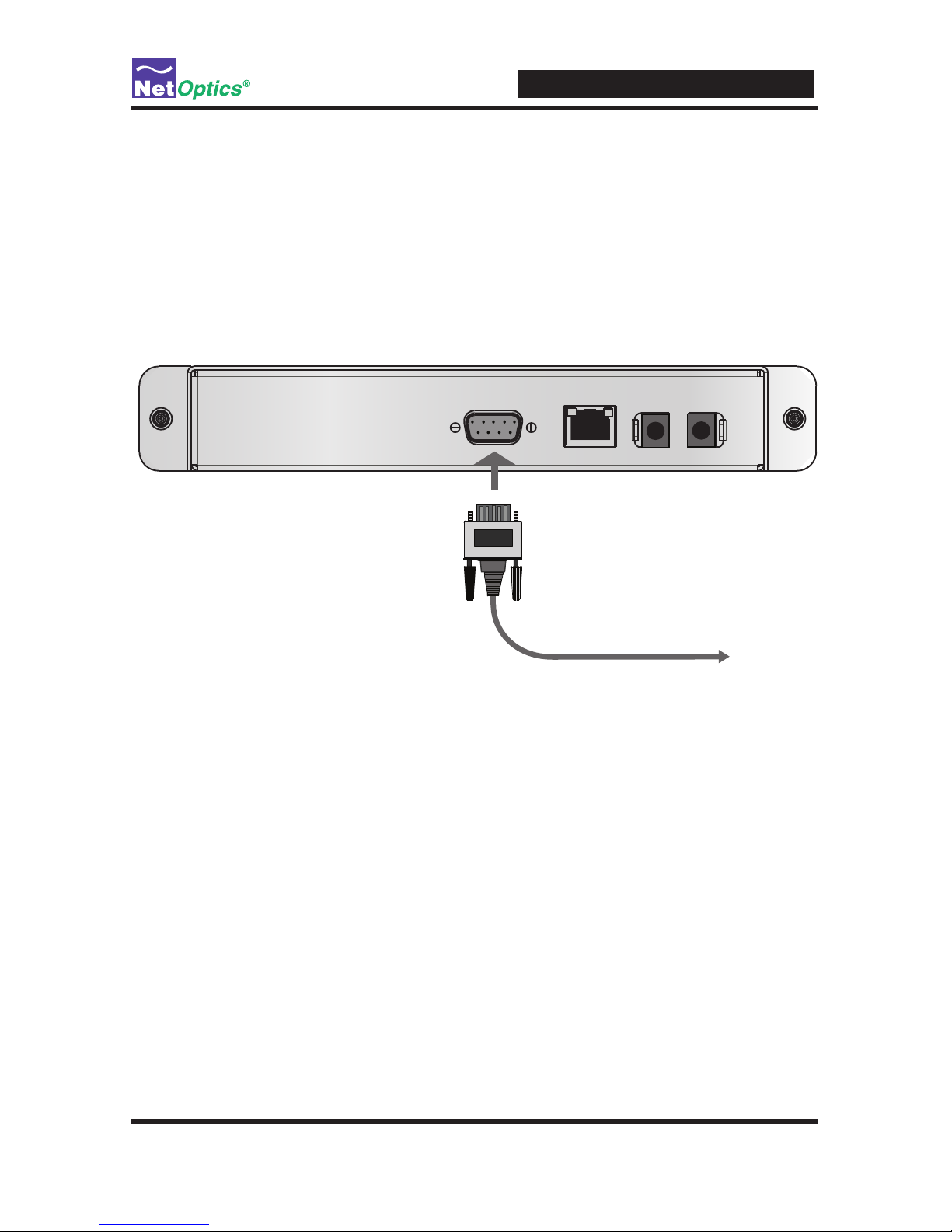
Connecting to the CLI Interface
All conguration options, status, and statistics are accessible from the iBypass
Switch Command Line Interface. You will now set a new username and password,
IP address for the iBypass Switch, utilization threshold levels for Port A and B, and
the current date and time. Other parameters are optional and dependent on your
installation. To do this conguration, you need to connect an RS232 DB9 cable to
the back of the iBypass Switch and to your computer.
To computer with
terminal emulation software
Management
Port
RS232
Figure 7: RS232 DB-9 connecting to computer
Your computer needs to have terminal emulation software such as HyperTerminal
to access the iBypass Switch CLI via the RS232 cable..
To connect the CLI:
1. Connect a PC with terminal emulation software, such as HyperTerminal, to the
iBypass Switch using the RS232 DB-9 cable supplied with the iBypass Switch.
2. Launch the terminal emulation software and set communication parameters to:
19200 baud
8 data bits
No parity
1 stop bit
Noowcontrol
Page 17

iBypass Switches with Heartbeat
13
3. Power on the iBypass Switch. The Net Optics CLI banner and login prompt
appear in the Terminal Emulation software (see below). The login default is
netoptics.
*************************************
* Net Optics Command Line Interface *
*************************************
login: netoptics
password:
4. Enter the password. The default password is netoptics.
*************************************
* Net Optics Command Line Interface *
*************************************
login: netoptics
password: netoptics
Congure the iBypass Switch with the CLI
You should be logged into the iBypass CLI using terminal emulation software.
If you are not, see the instructions on the previous page.
The default values for this IBypass Switch are:
Management Port: Enabled
IP Address: 192.168.2.100
Netmask: 255.255.0.0
Threshold Port A: 50%
Threshold Port B: 50%
Threshold Port 1: 50%
Threshold Port 2: 50%
Username: netoptics
Password: netoptics
Auto-negotiate: On (IBP-HBCU3 only)
Port speed: Gigabit (IBP-HBCU3 only)
For security reasons, some parameters can only be set with the CLI. A complete
list of CLI commands is in Appendix B.
Page 18

iBypass Switches with Heartbeat
14
You will use the CLI now to:
• Change the login and password
• Assign a new IP address
• Change utilization thresholds
• Set the date and time
• Display and check the CLI settings
• Disable and enable the Management Port
Your terminal emulator should be displaying the Net Optics prompt shown below.
If it does not, follow the directions on the previous page.
Net Optics>
You can change most settings later from one of the remote manager interfaces (for
more information about remote interfaces, see Chapters 4 and 5).
Change the iBypass Switch Username and Password
1. Change the username by entering the following command:
set username <new username>
2. Change the password by entering the following command:
set password <new password>
3. Record the username and password in a secure location.
Assign a New iBypass Switch IP Address
To change the iBypass Switch IP address:
Enter set ip <new ip address>.
Example: Enter set ip 10.60.10.100 to set the iBypass Switch IP address to
10.60.10.100.
Web Manager and System Manager will connect to the device at this address.
Page 19

iBypass Switches with Heartbeat
15
Change Port Utilization Threshold Levels
1. Enter set threshold port a <new level> to set a percentage of available band-
width for Port A. Exceeding this limit will trigger the alarm.
Example: Enter set threshold port a 30 to set the alarm threshold level for
trafc received on Port A to 30%.
2. Enter set threshold port b <new level> to set a percentage of available bandwidth for Port B. (Exceeding this limit will trigger the alarm.)
Example: Enter set threshold port b 30 to set the alarm threshold level for
trafc received on Port B to 30%.
Set the Current Date and Time
Enter set time <mm/dd/yyyy-hh:mm:ss> where mm is month, dd is day of the
month, yyyy is year, hh is hour, mm is minutes of the hour, and ss is seconds.
Time is based on the 24-hour clock.
Display and Check Current Settings
Enter show set.
The CLI displays the current setting, similar to the example below.
Net Optics> show set
show set
Model: Net Optics Management System for HB Bypass
System Time: 03/29/2011 18:25:14
IP Address: 10.60.4.20
Netmask: 255.0.0.0
Manager: 192.168.0.1
Gateway: 10.0.0.1
Management Port: ON
Port Parameter: 0X37
Threshold A: 50
Threshold B: 50
Threshold 1: 50
Threshold 2: 50
Port LFD: OFF
Port Detection: OFF
Timeout Period: 1
Retry Number: 3
Web Refresh Interval: 150
Page 20

iBypass Switches with Heartbeat
16
Use the CLI Help Command
1. Enter Help at the Net Optics prompt. The list of help topics is displayed.
Net Optics> help
*************************************
* Net Optics Command Line Interface *
*************************************
Usage: "help <variable>"
display - Toggle internet accessibility and LCD display.
echo - Turn on or off echoing of characters.
help - This help screen.
ping - ping a Network IP address.
reset - Reset options.
set-Congurevariousoptions.
show-Showcurrentcongurationsandstatus.
web-Congurewebdownloadparameter
2. To view the syntax for changing the iBypass Switch conguration parameters,
enter help set.
Net Optics> help set
help set
Usage: "set <variable> <value>"
(typehelpset<variable>forspecicinfo)
<variable> <value>
community <op> <comm> - set <read,write> <community> string
detection <on|off> - bypass detection
gateway <d.d.d.d> - IP address of Default Gateway
ip <d.d.d.d> - IP address of the device
lfd <on|off> - link fault detection
manager <d.d.d.d> - IP address of the SNMP manager
netmask <d.d.d.d> - Network Mask of the device
parameter port <64|96> - 64=Disable, 96=Enable monitor ports
password <password> - password
retry <1-255> - Number of missed Heartbeats for Bypass ON
timeout <0-255> - Heartbeat timeout period in mSec: 0 forces
Bypass ON
username <name> - username
threshold port <A|B|1|2> - <0-100> - Utilization Threshold for port in %
time <mm/dd/yyyy-hh:mm:ss> - Current Date and Time
txpacket<xx-xx-xx...>-HeartbeatPacketcontents(128bytesmax)
web-refresh <interval> - web refresh interval in seconds
3. Repeat with the variable of interest to view the syntax for all commands available
from the CLI. For more information about CLI commands, see Appendix B.
Page 21

iBypass Switches with Heartbeat
17
Do not disconnect the DB9 cable yet from the RS232 port. You will use it once more
to turn the iBypass Switch display on and off.
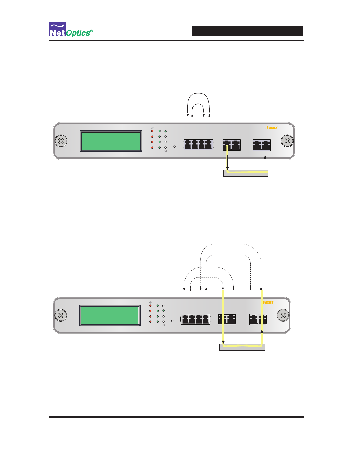
Connect the iBypass Switch to the Network
To connect the iBypass Switch to the network:
1. Connect Network Port A to the appropriate switch, server or router using an LC
type ber cable or CAT5e copper cable.
2. Connect Network Port B to the appropriate switch, server or router using an LC
type ber cable or CAT5e copper cable.
To Switch, Server, or Router (DCE)
To Switch, Server, or Router (DTE)
1
2
BYPASS
LINK
B
A
1
2
ON
OFF
B
A
1
2
OUT INOUT IN OUT IN OUT IN
RESET
Network
A B 1 2
Monitor
Switch
10 GigaBit
Figure 8: Connect the iBypass Switch to the Network
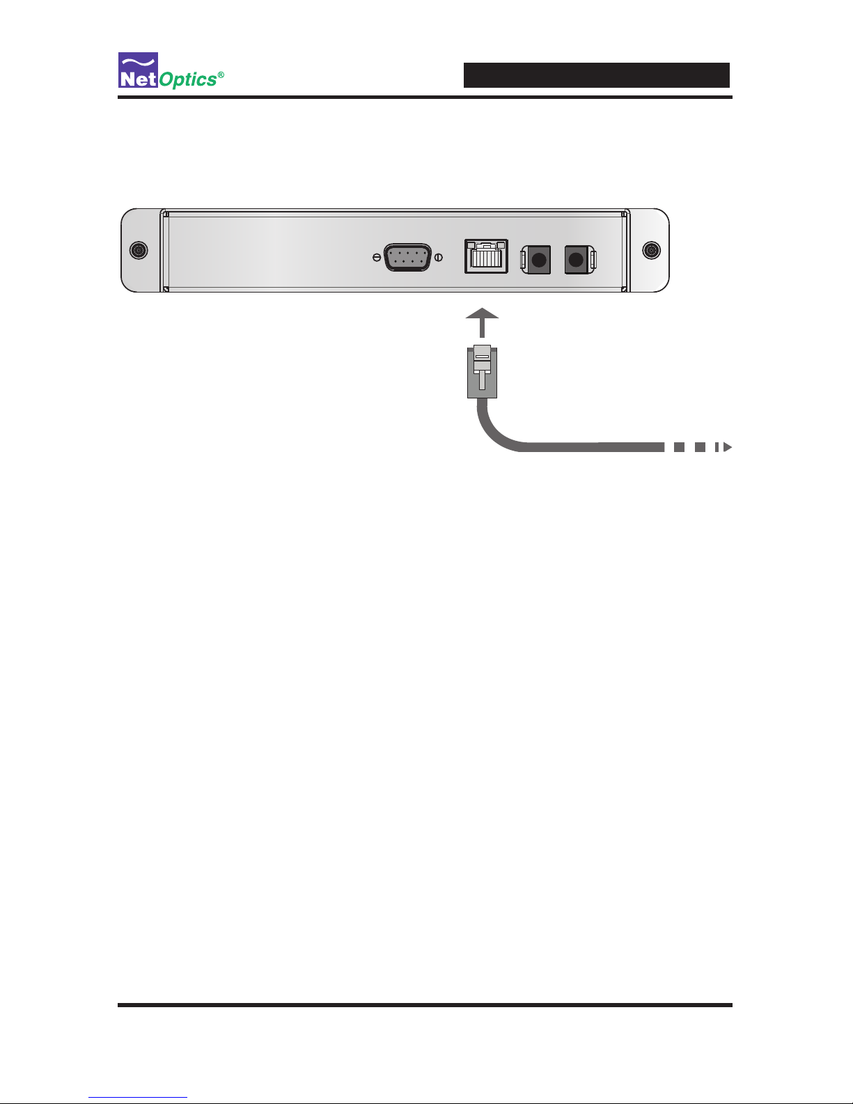
Connect the Management Port to the Network
To use either of the remote interfaces you must connect the Management Port on the
back of the unit to the network.
To connect the Management Port:
Page 22
iBypass Switches with Heartbeat
18
1. Connect a CAT5e cable to the Management Port as shown in the following gure.
2. Connect the other end to a network switch or hub.
To network switch or hub
Management
Port
RS232
Figure 9: Connecting the Management Port
Disable, Enable and Check the Management Port
The CLI display command toggles the display on and off. From the terminal
emulation software, do the following:
1. Enter show display to view the current setting. The default value is ON.
2. Enter display. Now look at the front of the iBypass Switch. Access from the
Management Port is blocked and the iBypass Switch front panel does not display
utilization or peak information.
3. Enter display again to restore the display and remote interfaces.
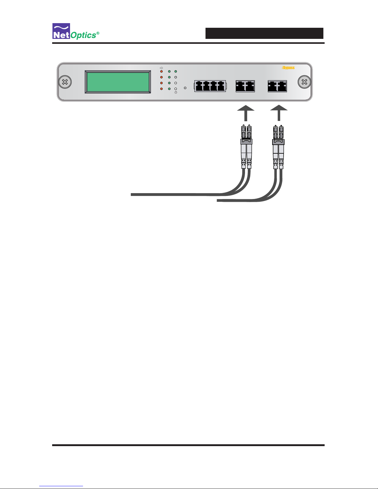
Connect a Monitoring Device to the iBypass Switch
The iBypass Switch is delivered with two monitor cables for monitoring device
installation. Connect the cables to the monitoring device.
1. Connect Monitor Port 1 to the appropriate port on the monitoring device using
the LC type ber cable or CAT5e copper cable.
2. Connect Monitor Port 2 to the appropriate port on the monitoring device using
the LC type ber cable or CAT5e copper cable.
Page 23
iBypass Switches with Heartbeat
19
1
2
BYPASS
LINK
B
A
1
2
ON
OFF
B
A
1
2
OUT INOUT IN OUT IN OUT IN
RESET
Network
A B 1 2
Monitor
To Monitoring Device
To Monitoring Device
Switch
10 GigaBit
Figure 10: Connecting the Monitoring Devices
Check the Installation
You have connected the iBypass Switch to the network, to the monitoring device
and to power. It should be functioning correctly now. Check the status of the following:
• Check that at least one power LED is illuminated.
• Check the link status LEDs located on the front panel to verify that trafc is
passing through the switch.
• Check the display for utilization and peak information.
• Verify that the monitoring device is receiving trafc from the iBypass Switch.
• Verify that the Management Port is functional by typing the iBypass Switch's
IP address in your Web browser. Net Optics' Web Manager should appear. If it
does not, check the Management Port cables and connections and verify that the
Display option in the CLI is set to ON.
Page 24

iBypass Switches with Heartbeat
20
Chapter 4
Web Manager
This chapter describes how to monitor and control individual iBypass Switches
using Web Manager. The following topics are covered:
• Accessing Web Manager
• Viewing iBypass Switch Status
• Controlling iBypass Switch Connections
• Using the iBypass Switch Web Manager
The Web Manager browser-based interface allows you to change conguration
settings, view status, and to control which Network ports are connected to the
monitoring devices.
Note: ____________________________________________________________________
To access Web Manager, Display must be set to ON from the CLI. For more
information, see Using the Command Line Interface in Chapter 2.
__________________________________________________________________________
Access Web Manager
Web Manager is a browser-based interface that provides access to any iBypass
Switch with an IP address. Web Manager supports all common browsers.
To access Web Manager:
1. Open an Internet browser on your computer.
2. Enter the iBypass Switch IP address in the URL. The default IP address is
192.168.2.100. Web Manager displays, as shown in the following gure.
Page 25
iBypass Switches with Heartbeat
21
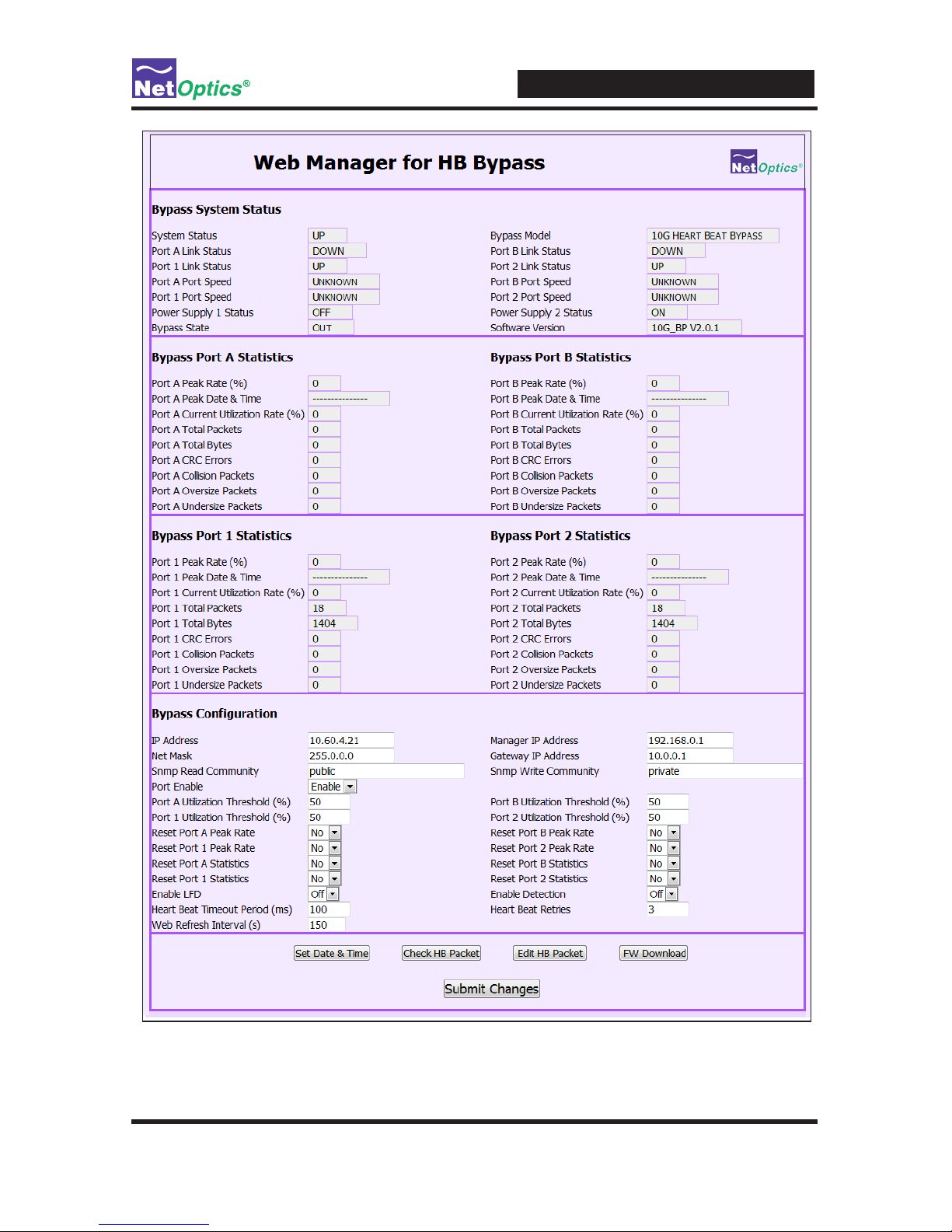
Figure 11: Web Manager main screen
Page 26

iBypass Switches with Heartbeat
22
3. Change any Conguration elds. The following table describes the elds on the
Web Manager window. You cannot change the Status or Statistics elds; they
are read-only.
Field Name Description
Bypass System Status
System Status Status of the iBypass, UP or DOWN
Link Status Status of the port Link, UP or DOWN
Port Speed Speed for the port
Power Supply
Status
Status of the power supply, ON or OFF for this power supply
Bypass State Indicates the bypass state, ON or OFF
Bypass Model Indicates the iBypass model number.
Bypass Port Statistics—Port A, Port B, Port 1, Port 2 (Four screen sections)
Peak Rate Peak trafc rate on the port
Peak Date and
Time
Time of the peak trafc, formatted as:
mm/dd/yyyy hh:mm:ss
Current Utilization
Rate %
The current utilization rate on port
Total Packets The total number of packets traversing this port since the
last device reset.
Total Bytes The total number of bytes traversing this port since the last
device reset.
CRC Errors The number of Cyclical Redundancy Check errors on this
port since the last device reset.
Collision Packets The total number of link collisions seen by this port since the
last device reset.
Oversize Packets The total number of oversize packets traversing this port
since the last device reset.
Undersize Packets The total number of undersize packets traversing this port
since the last device reset.
Bypass Conguration
IP Address IP Address for the iBypass Switch
nnn.nnn.nnn.nnn. When you
change the IP address, Web Manger lose its connection with
the device; type the new address into the browser's address
bar to connect again.
Net Mask Netmask for iBypass Switch subnet
nnn.nnn.nnn.nnn.
Page 27

iBypass Switches with Heartbeat
23
Field Name Description
Manager IP
Address
IP Address for the SNMP Manager
nnn.nnn.nnn.nnn.
Gateway IP
Address
IP Address for the default Gateway
nnn.nnn.nnn.nnn.
SNMP Read
Community
SNMP community string controlling MIB GET and WALK
access; 3 to 31 characters, no embedded spaces.
SNMP Write
Community
SNMP community string controlling MIB SET access; 3 to 31
characters, no embedded spaces.
Port Utilization
Threshold (%)
Percent utilization of Port A, Port B, Port 1, Port 2 (separate
parameter for each port).
Reset Peak Rate Reset (toggle Yes/No) the rate of peak usage on Port A,
Port B, Port 1, Port 2 (separate control for each port). The
Peak Rate is a trafc measurement during peak time. The
Net Optics iBypass Web Manager will capture the highest
peak rate and time, and then display them in the Statistics
section.
Assume that these peaks occurred:
8:00 AM = 1%;
9:00 AM = 2%;
10:00 AM = 50%;
11:00 AM = 15%;
12:00 AM = 20%;
1:00 PM = 30%;
2:00 PM = 40%;
3:00 PM = 30%;
4:00 PM = 20%;
5:00 PM = 60%.
In the Status window, at 10 AM, 50% was the Peak Rate
and the display remained that way until 5 PM if no reset was
done. If a reset was done at 11 AM, then the Peak Rate
changed to 20% at noon, then 30% at 3 PM, then 40% at 2
PM, and then 60% at 5 PM.
Reset Statistics Reset (toggle YES/NO) the statistics of Port A, Port B, Port
1, Port 2 (separate control for each port).
Enable LFD Enable/Disable Link Fault Detection (LFD). When LFD is
enabled, if one network link goes down, the other link is
automatically downed to propagate the condition.
Heartbeat Timeout
Period(s)
Time between sending Heartbeat Packets. If this parameter
is set to 0, the Switch is forced into Bypass ON mode. On
10 GigaBit models, the time is in milliseconds and the default
value is 100. On other models, the time is in seconds and the
default value is 1.
Page 28
iBypass Switches with Heartbeat
24
Field Name Description
Enable Detection Turn Bypass Detect ON and OFF.
Heartbeat Retries Number of heartbeats that do not come back from a device
before an iBypass unit stops sending trafc through that
monitoring device; the default is 3. Heartbeat packets
continue to be sent and if one comes back from the attached
device, trafc ow to the device resumes.
Web Refresh
Interval
Number of seconds (from 20 to 900) between automatic
reloads of the Web Manager page;.
4. Save changes to the iBypass Switch by clicking Submit Changes at the bottom
of the page.
5. To update the display, click your browser's refresh button.
The following sections explain the command buttons at the bottom of the
Web Manager window.
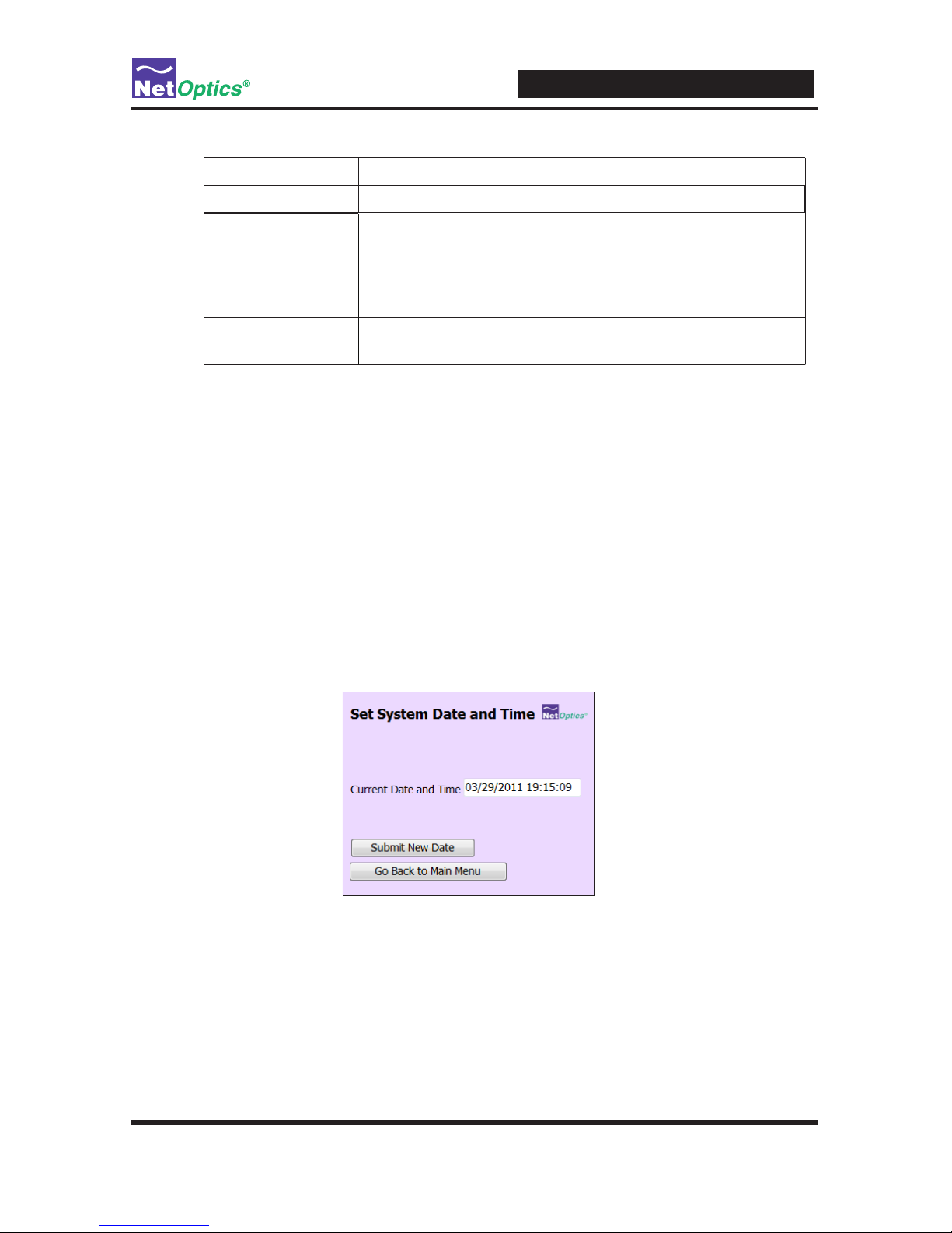
Set Date and Time Window
Use the Set Date and Time window to set the current date and time.
1. Click Set Date & Time on the main window to see the Date & Time window.
2. In the Current Date and Time text entry box type new values.
Be sure to retain the proper mm/dd/yyyy hh:mm:ss format.
3. Click Submit New Date to save the changes.
4. Click Go Back to Main Menu to return to the main Web Manager window.
Page 29

iBypass Switches with Heartbeat
25
Check/Change the Heartbeat Packet from Web Manager
Use the Heartbeat window to view hexadecimal information about the current
Heartbeat packet or to edit the Net Optics Heartbeat packet and create your own
customized Heartbeat packets (one for each monitored device). You can do this
from Web Manager or System Manager.
To view the Heartbeat packet:
1. Click Check HB Packet. The Display Heartbeat Packet window appears.
2. Select Yes and click Apply. The Heartbeat packet contents are refreshed.
3. Click Go Back to Main Menu to return to the main Web Manager window.
To change the Heartbeat packet:
1. Click Edit HB Packet. The Edit Heartbeat Packet window appears.
Page 30

iBypass Switches with Heartbeat
26
2. Change the hexadecimal values; be sure to adhere to IP address and MAC
address conventions and include correct CRC bytes at the end of the packet.
3. Click Submit the Packet to save the changes.
4. Click Go Back to Main Menu to return to the main Web Manager window.
Note: The default Heartbeat packet is:
Packet Contents (Hex) Description
----------------------------- ----------------
00 50 C2 3C 60 00 MAC DA Net Optics
00 50 C2 3C 60 01 MAC SA Net Optics
08 00 Packet Type IP
45 00 00 3C 18 D2 00 00
80 01 0A FF 0A 02 01 DC
0A 01 01 12 08 00 37 5C
02 00 14 00 61 62 63 64
65 66 67 68 69 6A 6B 6C
6D 6E 6F 70 71 72 73 74
75 76 77 61 62 63 64 65
66 67 68 69
B8 8E 1C A9 CRC
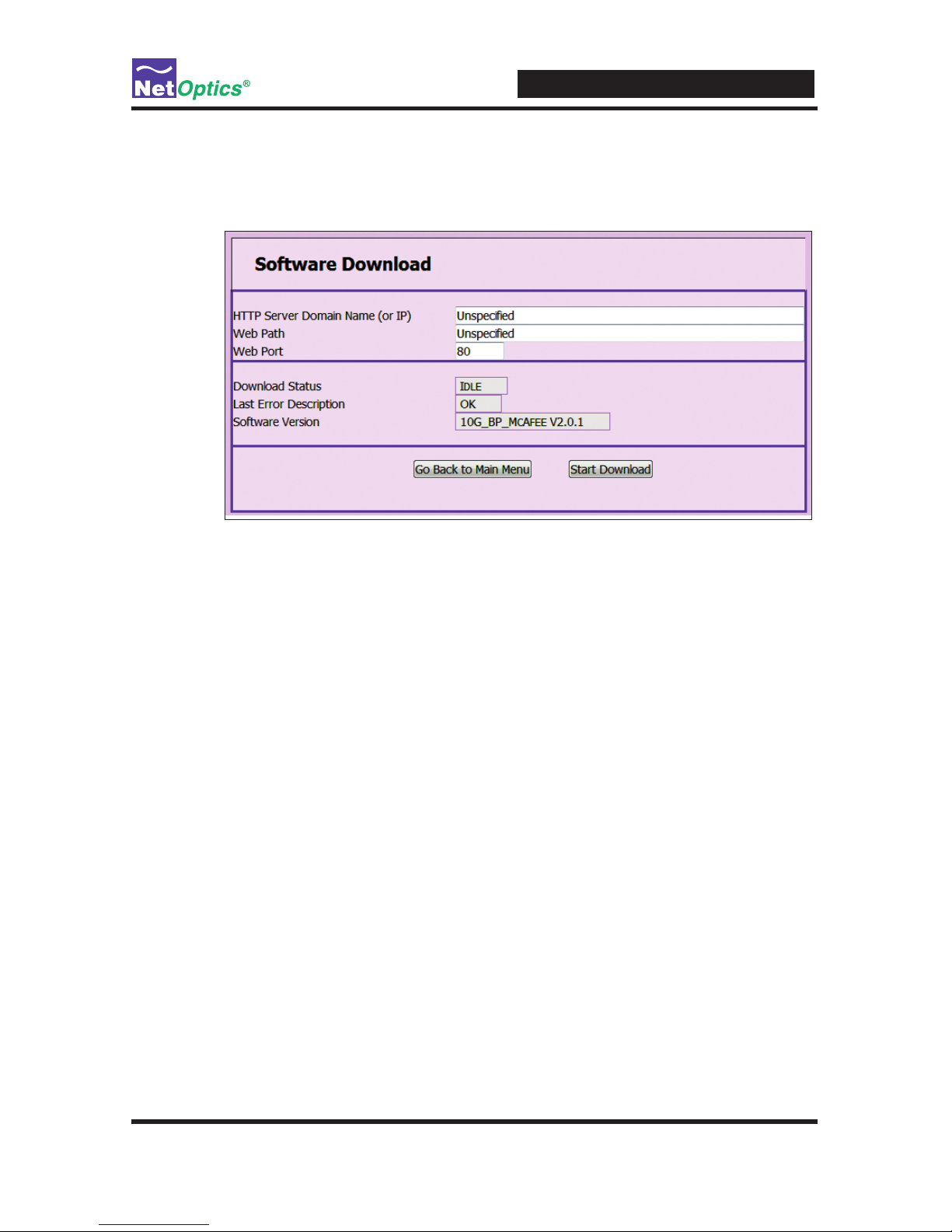
Download and Install New Software
Use the Software Download window to download and install new software into
the iBypass Switch. You can nd software release information in the Net Optics
Customer Portal.
Page 31
iBypass Switches with Heartbeat
27
To download and install new iBypass Switch software:
1. Click SW Download. The Software Download window appears.
2. Type the URL or IP address of the software download server (HTTP protocol)
into the HTTP Server Domain Name (or IP) box.
3. Type the name of the new software image le into the Web File box.
4. Type the port number into the Web Port box if you want to use a port other than
the standard HTTP port 80.
5. Double-check your entries and then click Start Download. The download
progress is indicated in the Download Status box and the version number of the
downloaded software image le is shown in the Software Version box.
6. Click Go Back to Main Menu to return to the main Web Manager window.
Tips! ____________________________________________________________________
See the Technical Note Upgrading iTap and iBypass Software Using HFS for
instructions for setting up a Web File Server for downloading software to the
iBypass Switch.
Software download through Web Manager and SNMP can be disabled for
security purposes using the CLI command remote-download off. The default
setting is remote-download on.
__________________________________________________________________________
Page 32

iBypass Switches with Heartbeat
28
Set Port Parameters
Use the Port Settings window to enable and disable the ports, and to select whether the
port auto-negotiates for link speed and duplex mode, or select a xed speed and duplex
setting. Speed selection is only available on the 10/100/1000 iBypass Switch.
All four ports are always set to the same mode. They must be the same in order to pass
trafc successfully.
To set the port parameters:
1. Click Set Port Parameters. The Port Settings window appears.
2. Select Enable or Disable to bring the link up or down.
3. Select Yes to enable link autonegotiation or No for xed settings.
4. Select the link speed if it is a 10/100/1000 iBypass Switch, Gigabit for
1000 Mbps, 100 BT for 100 Mbps, or 10 BT for 10 Mbps. You must select Ye s
for one speed and No for the other two.
5. Select Full or Half for the duplex mode.
6. Double-check your entries and then click Submit Changes. All four ports are set
to the selected mode.
7. Click Go Back to Main Menu to return to the main Web Manager window.
Page 33

iBypass Switches with Heartbeat
29
Chapter 5
System Manager
Overview
This chapter describes how to install and use the Net Optics System Manager. Use
the System Manager to change system settings, to view system status, and retrieve
data from congured Net Optics iBypass Switch devices. The following topics are
covered:
• Install System Manager
• Explore System Manager
• Create a Sytem Manager Group
• Delete a Sytem Manager Group
• Add iBypass Switches to a Group
• Delete an iBypass Switch
• Congure an iBypass Switch
• View iBypass Switch Information
• Change a Heartbeat Packet from System Manager
Page 34

iBypass Switches with Heartbeat
30
Install System Manager
The executable installation le for System Manager is distributed on the CD included with the iBypass Switch.
To install System Manger:
1. Locate Setup.exe on the CD and double click it. The License Agreement appears.
2. After reading the agreement, select I Agree and click Next to install System
Manager. The Welcome dialog appears.
3. Click Next. The Select Installation Folder dialog box appears.
4. To install in the default folder, select the default path in the Folder: text box. To
install in a different location, either type the path in the Folder: text box or click
Browse to nd another location.
5. To check the space available for System Manager on the selected drive, click
Disk Cost.
6. To limit access to System Manager to the current user of the PC, select Just Me.
To allow access to any user logged into the PC, select Everyone.
7. Click Next. The Conrm Installation dialog displays.
Page 35
iBypass Switches with Heartbeat
31
8. Click Next to continue with the installation. The Progress dialog displays.
To stop the installation, click Cancel. When the installation is complete, the
Installation Complete dialog box appears.
9. Click Close. System Manager is now installed on your computer and a
Net Optics shortcut icon has been placed onto your desktop.
Explore System Manager
This section explains the features and functions of System Manager. With System
Manager you can:
• Create iBypass Switch groups
• Add and delete iBypass Switches from the system
• Remotely congure iBypass Switches
• View trafc utilization and peaks
• View trafc statistics
NOTE ___________________________________________________________________
In order to access an iBypass Switch with System Manager, the Display option
must be set to ON in the CLI. For more information, see Using the Command Line
Interface in Chapter 2.
__________________________________________________________________________
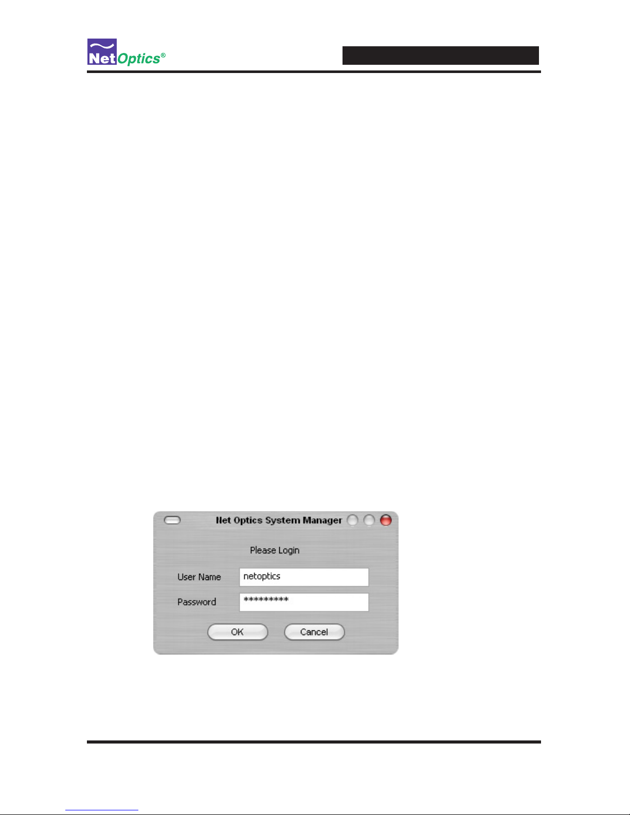
To access System Manager:
1. Double-click the System Manager icon on your PC desktop. The login box appears.
Page 36
iBypass Switches with Heartbeat
32
2. Log in with the default User Name netoptics and Password netoptics. The
initial System Manager window appears.
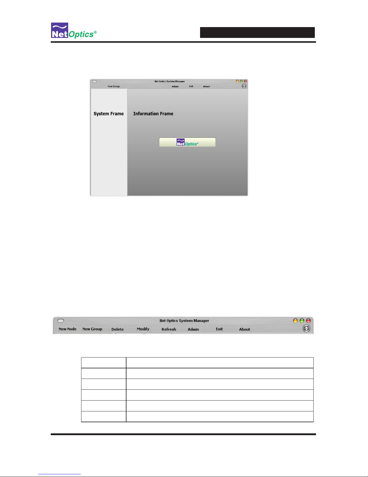
A new System Manager does not yet show any Net Optics units. The System
Frame portion of the window (left side) displays iBypass Switches and Groups as
you add them to the system. The Information Frame portion of the window (right
side) displays Status, Conguration, and Control information for the selected unit.
Tip! _____________________________________________________________________
To use pop-up menu shortcuts, click your right mouse button in the System Frame.
__________________________________________________________________________
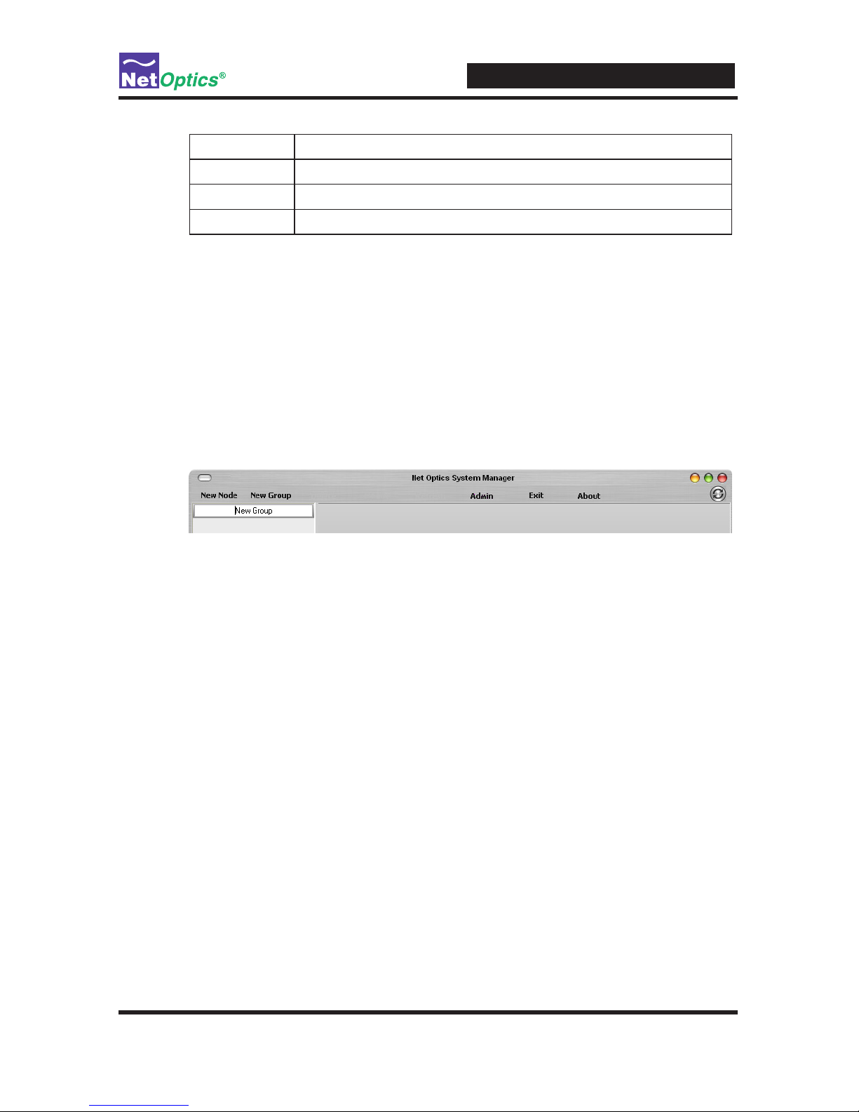
Using the Toolbar
The following gure shows the System Manager toolbar.
The table below describes the icons found on the toolbar.
Tool Description
New Device Add devices to a group
New Group Create an iBypass Switch group
Delete Delete devices from the system
Modify Change the device name, IP address, model, and add notes
Refresh Refresh the data display
Page 37
iBypass Switches with Heartbeat
33
Tool Description
Admin Change username/password
Exit Close Net Optics System Manager
About View information about System Manager
Create a System Manager Group
Organize iBypass Switches or other Net Optics devices into groups for quick access. Devices must belong to a group. If you add an iiBypass Switch when there is
no group, a group is created automatically.
To create an iBypass Switch group:
1. Click New Group in the toolbar. A new group bar appears in the System Frame
as shown in the following gure.
2. Either accept the default group name or edit it by typing the new name and
pressing Enter.
Delete a System Manager Group
You can delete a group; however, all devices within that group will also be deleted
from System Manager.
Note: ____________________________________________________________________
Deleting an iBypass Switch from System Manager does not affect the current
operating status of the iBypass Switch. The iBypass Switch continues to pass trafc
from the Network ports to the Monitor Ports. However, you will not have visibillty
from System Manager unless it is added back in.
__________________________________________________________________________
To delete a group:
1. Right-click the group that you want to delete.
2. Select Delete from the pop-up menu. The group and all associated devices are
deleted from System Manager.
Page 38
iBypass Switches with Heartbeat
34
Add Devices to a System Manager Group
To congure and control iBypass Switches with System Manager, you must add
each iBypass Switch to a group. Once you have added an iBypass Switch, you can
congure, modify, and delete it from System Manager.
Note: ____________________________________________________________________
The iBypass Switch must be connected to the network as described in Chapter 2
before it can be added to System Manager.
__________________________________________________________________________
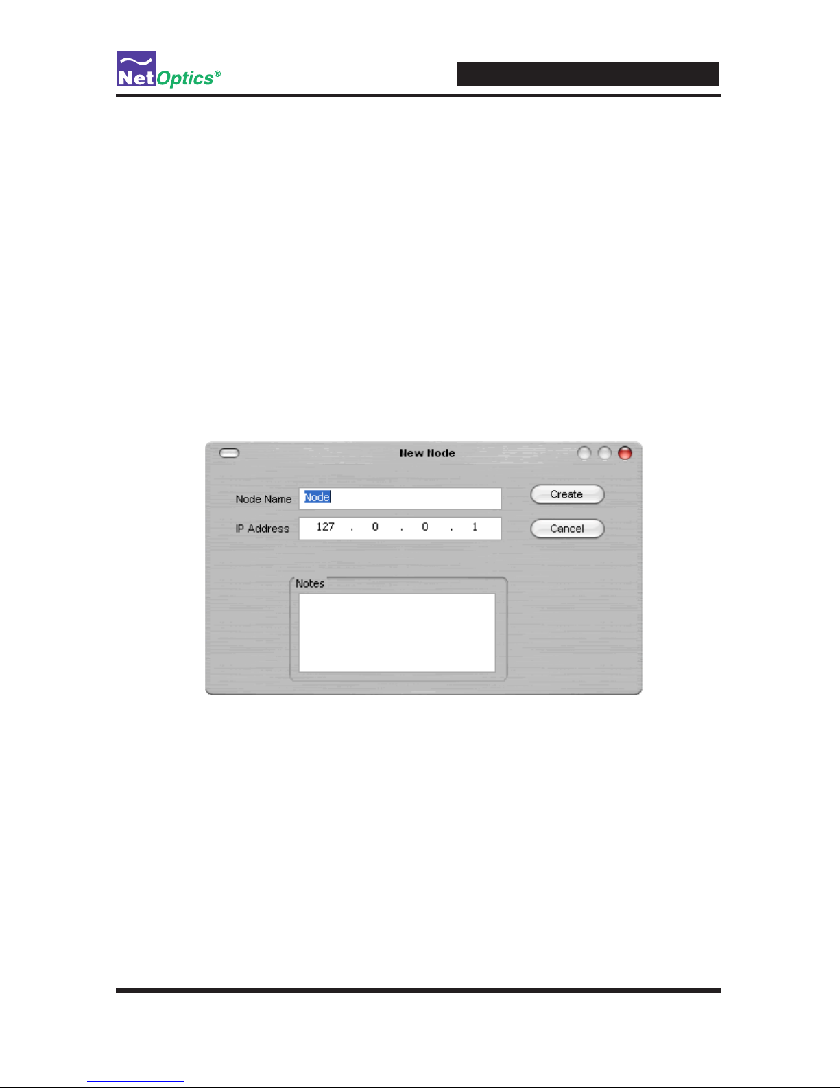
To add an iBypass Switch to the system:
1. Select the group where the iBypass Switch will be added.
2. Click New Device in the toolbar. The New Device dialog box appears.
3. Enter a name for the iBypass Switch in the Node Name text box. Each Node
Name in the system must be unique.
4. Enter the IP address of the iBypass Switch in the IP Address text box. The IP
address must be unique on the network.
5. Enter any relevant information about the iBypass Switch in the Notes text box.
Page 39
iBypass Switches with Heartbeat
35
6. Check your settings and click Create. The iBypass Switch appears in the
system frame.
The indicator to the right of the iBypass Switch picture blinks green when the
iBypass Switch is functioning normally. If there is an alarm condition on the iBypass
Switch, the indicator blinks red. If System Manager cannot communicate with the
iBypass Switch, the switch graphic is grayed. Check that the iBypass Switch is con-
nected to the network and verify the conguration information.
Repeat Steps 1-6 for each iBypass Switch you are adding to System Manager.
Tip! _____________________________________________________________________
To change the display order of iBypass Switches, click and drag them into the
desired order.
__________________________________________________________________________
Delete an iBypass Switch from System Manager
You can delete an iBypass Switch from System Manager when you remove an iBypass Switch from your network. If you have removed an iBypass Switch from the
network, System Manager continues to poll the iBypass Switch IP address for data
until you delete the iBypass Switch from System Manager.
To delete an iBypass Switch from System Manager:
1. Select the device you want to delete by clicking its icon.
Page 40
iBypass Switches with Heartbeat
36
2. Click Delete in the toolbar. A conrmation dialog box appears.
3. Click Yes to delete the iBypass Switch from System Manager.
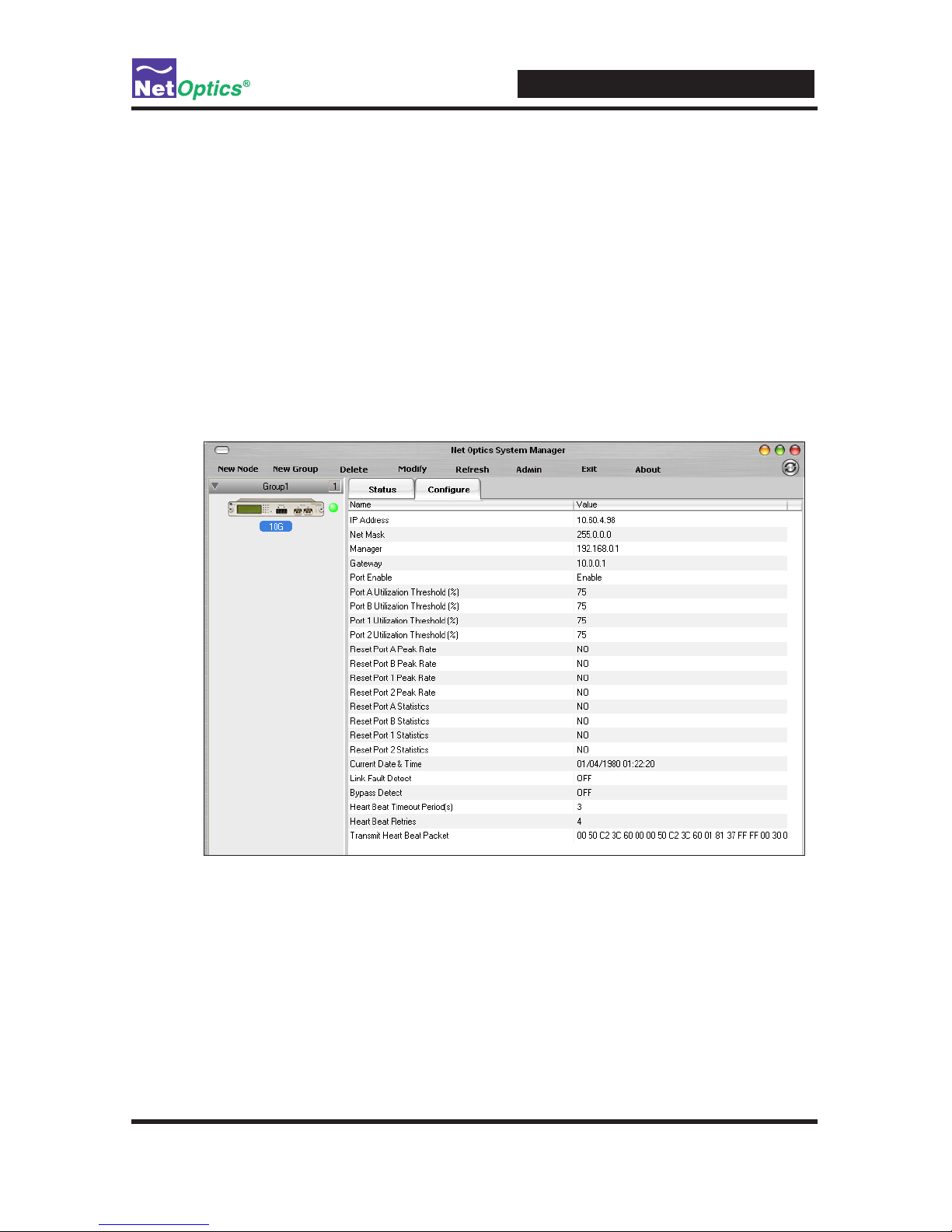
Congure an iBypass Switch from System Manager
Set the conguration parameters of an added iBypass Switch from the Congure tab.
TocongureaniBypassSwitch:
1. Click the icon of the iBypass Switch you want to congure.
2. Click the Congure tab.
3. Click the value eld for the parameter you want to congure.
4. Select an option from the drop-down list or enter a new value from your
keyboard.
The table on the following page describes the iBypass Switch options on the
Congure Tab.
Page 41

iBypass Switches with Heartbeat
37
iBypass Switch Congure Options
Field Name Description
IP Address IP address of the iBypass Switch; the default IP address
is 10.60.0.123. Change the IP address by typing a new
one in the box. When you change the IP address, System
Manager will lose its connection with the device until you
put the new address in the device in the System Frame.
Netmask The netmask; the default netmask is 255.255.0.0. Change
the netmask by typing a new one in the box.
Manager IP address of either the host PC running System Manager
over a WAN or the third-party SNMP management tool.
Change the IP address by typing a new one in the box.
Gateway IP Address IP address of the current WAN gateway. Change the
gateway address by typing a new one in the box.
Port Enable ENABLE/DISABLE the monitor ports.
Port A Utilization
Threshold
Percentage level at which this port use triggers an alarm;
as default the Port A alarm is triggered when Port A exceeds 50% utilization.
Port B Utilization
Threshold
Percentage level at which this port use triggers an alarm;
as default the Port B alarm is triggered when Port B exceeds 50% utilization.
Port 1 Utilization
Threshold
Percentage level at which this port use triggers an alarm;
as default the Port 1 alarm is triggered when Port 1 exceeds 50% utilization.
Port 2 Utilization
Threshold
Percentage level at which this port use triggers an alarm;
as default the Port 2 alarm is triggered when Port 2 exceeds 50% utilization.
Reset Port A Peak
Rate
This value is NO unless you change it to YES. If you set
it to YES, as soon as the port reset is complete, it returns
to NO.
Reset Port B Peak
Rate
This value is NO unless you change it to YES. If you set
it to YES, as soon as the port reset is complete, it returns
to NO.
Reset Port 1 Peak
Rate
This value is NO unless you change it to YES. If you set
it to YES, as soon as the port reset is complete, it returns
to NO.
Reset Port 2 Peak
Rate
This value is NO unless you change it to YES. If you set
it to YES, as soon as the port reset is complete, it returns
to NO.
Page 42

iBypass Switches with Heartbeat
38
Field Name Description
Reset Port A Statistics
This value is NO unless you change it to YES. If you set
it to YES, as soon as the port reset is complete, it returns
to NO.
Reset Port B Statistics
This value is NO unless you change it to YES. If you set
it to YES, as soon as the port reset is complete, it returns
to NO.
Reset Port 1 Statistics
This value is NO unless you change it to YES. If you set
it to YES, as soon as the port reset is complete, it returns
to NO.
Reset Port 2 Statistics
This value is NO unless you change it to YES. If you set
it to YES, as soon as the port reset is complete, it returns
to NO.
Current Date & Time Click the existing date and adjust it with the up and down
arrows.
Link Fault Detect Turn Link Fault Detection (LFD) ON or OFF. When LFD is
ON, if one network link goes down, the other link is automatically downed to propagate the condition.
Bypass Detect Turn Bypass Detect ON or OFF. In most environments,
Bypass Detect should be OFF.
Heartbeat Timeout
Period(s)
Number of milliseconds (0–100) between Heartbeat Packets
sent from the iBypass unit to a connected monitoring device.
The default is 1 millisecond. If this parameter is set to 0, the
Switch is forced into Bypass ON mode.
Heartbeat Retries Number of heartbeats that do not come back from a device
before an iBypass unit stops sending trafc through that
monitoring device; the default is 3. Heartbeat packets
continue to be sent and if one comes back from the
attached device, trafc ow to the device resumes.
Transmit Heartbeat
Packet
View or change this heartbeat packet. The default is 00 05
c2 3c 60 00 00 50 c2 3c 60 01 08 00
The new conguration parameters take effect the next time System Manager polls
the iBypass Switch. If System Manager detects a change when it pools, a circled
arrow appears next to the value until the next polling.
Page 43

iBypass Switches with Heartbeat
39
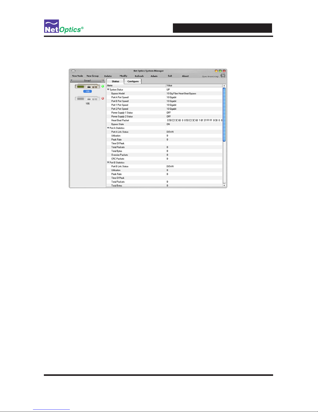
View iBypass Switch Information from System Manager
System Manager allows you to view the current iBypass Switch conguration information, including the Monitor Port connections.
To view iBypass Switch information:
1. Click the image of the iBypass Switch you want to view in the System Frame.
The Status tab is a read-only list of information from the iBypass Switch. Use the
scroll bar and arrows to view the entire list if necessary.
TIP! _____________________________________________________________________
Fields that have been updated since the last refresh display with a circle and arrow
just to the left of the value eld.
__________________________________________________________________________
The table on the following page describes the status elds.
Page 44

iBypass Switches with Heartbeat
40
iBypass Switch Status Fields
Field Description
System Status UP/DOWN
Bypass Model Fiber Heartbeat Bypass Model Number
Port Speed 10 GIGABIT
Power Supply 1, 2 OFF or ON
Heartbeat Packet Default Heartbeat packet which can be loaded using the "reset
defaults" command, or manually congured using the CLI.
The CLI command is "set txpacket xx-xx-xx-xx-etc. The
txpacket command must be a single line so it is a long
long data type.If you remove all the carraige returns and
comments (in parentheses) from the data below, you can
use it to congure the heart beat packet from the CLI.
The rst 12 bytes are the source and destination addresses.
They are followed by a sequence of bytes that dene the
packet type. The payload bytes are all 0's and the last four
bytes are the packet checksum (CRC).
set txpacket
00-50-c2-3c-60-00- (source address)
00-50-c2-3c-60-01- (destination address)
81-37-ff-ff- (packet type)
00-30-00-0000-00-40-04ec-a2-c6-1301-02-c6-1301-01-00-0000-00-00-00- (payload bytes)
00-00-00-0000-00-00-0000-00-00-0000-00-00-0000-00-00-00a0-07-37-99 (CRC)
Bypass State ON or OFF; see Chapter 1 for details.
Total Packets Total number of packets that have passed through the
iBypass unit since the last reset. When this value changes,
a circled arrow appears next to the value to alert you to the
change; if polling produces the same total packet result
twice in a row, the circled arrow disappears.
Page 45

iBypass Switches with Heartbeat
41
Field Description
Total Bytes Total number of bytes that have passed through the iBypass
unit since the last reset. When this value changes, a circled
arrow appears next to the value to alert you to the change;
if polling produces the same byte total twice in a row, the
circled arrow disappears.
Oversized Packets This function tracks the number of oversized packets since
the last reset. The Ethernet specication requires that no
packet be larger than 1518 bytes (including checksum).
Any packet that is larger than this is agged as an error and
discarded. These packets are also sometimes referred to
as “Jabbers”. Packets too big are almost always caused by
faulty hardware. The network adapter card on a link showing
a high rate of oversized packets should be replaced. Support IEEE 802.1q
CRC Packets This function tracks the number of CRC errors since the last
reset. MAC Frame CRC errors are the most common. Ethernet packets are encapsulated in a MAC frame that contains
a preamble, and a post-envelope CRC check. The Ethernet
adapter on the sending station creates the preamble, inserts
the packet data (addressing, protocol, data, etc.), calculates
a CRC checksum and inserts it at the end of the packet. If
the receiving station determines that the checksum is incorrect, the packet is assumed to be bogus and is discarded.
MAC frame CRC errors are typically caused by faulty
cabling. If the cabling connecting an Ethernet Adapter or
hub is faulty, the electric connection may be on and off
many times during a transmission. This on-and-off state can
interrupt parts of a transmission and damage the signal. If
the signal is interrupted partially during transmission, the
CRC checksum that was calculated by the network adapter
is longer valid and the packet is agged as a CRC error and
discarded.
CRC errors are common on a busy network, and a small
percentage does not reect a network problem. When the
percentage is large, or when a single station shows a larger
percent CRC errors, there is probably a problem.
Page 46

iBypass Switches with Heartbeat
42
Modify an iBypass Switch Name or Address from System
Manager
There are two ways to modify an iBypass Switch name or address. Either change
them from the Conguration Tab for the device, or use the Modify option in the
menu. The second method is described here..
To change a switch name or IP address from the Modify iBypass Switch dialog:
1. In the System Frame, select the image of the iBypass Switch you want to change.
2. Click Modify in the toolbar. The Modify iBypass Switch dialog appears.
3. Change the name or IP address of the iBypass Switch.
4. Optionally add notes.
5. Click Save Change.
Change a Heartbeat Packet from System Manager
The heartbeat packet for a 10 GigaBit iBypass Switch can be congured. To change
the default packet from the System Manager main menu, click Transmit Heartbeat
Packet and change the values.
Page 47

iBypass Switches with Heartbeat
43
Uninstalling System Manager
If available, it is highly recommended that software be uninstalled through this option of Windows.
1. Click the Start menu button and navigate to Settings/Control Panel.
2. Double Click Add/Remove Programs.
3. Locate the Net Optics System Manager icon and click "Install/Uninstall" or
"Change and Remove Programs buton.
4. Follow the instructions provided through the software wizard.
5. Upon completion some directories may need to be removed by hand.
Page 48

iBypass Switches with Heartbeat
44
Appendix A
Specications and Models
Specications
Electrical
Power Supply Input
100-240VAC, 0.5A, 47-63Hz
Power Supply Output
12V, 5A (10 GigaBit models), 3A (GigaBit models), 1.5A (10/100/1000 model)
Environmental
Operating Temperature
0˚C to 40˚C
Storage Temperature
-10˚C to 70˚C
Relative Humidity
10% min, 95% max, non-condensing
Mechanical
Dimensions
1.31” high x 12.4” deep x 8.75” (10 GigaBit models)
1.31” high x 11.0” deep x 8.75” (GigaBit and 10/100/1000 models)
IBPO-HBSR-XFP and IBPO-HBLR-XFP Connectors
(1) DB9 RS232 serial console port
(1) RJ45 management port
(2) XFP, SFP or RJ45 monitoring ports (depending on model)
(2) LC or RJ45 network ports (depending on model)
Indicators
(1) 2x16 Character LCD
(4) Link LEDs (Fiber Model)
(4) Threshold Alarm LEDs (not included on 10/100/1000 model)
(2) Power LEDs
(2) Bypass Mode LEDs
Page 49

iBypass Switches with Heartbeat
45
Optical SR Fiber Type
Fiber Type: Corning Multimode 62.5/125μm or 50/125μm, wavelength 850nm
Split Ratio Network Port Insertion Loss Monitor Port Insertion Loss
60/40 1.25 dB 1.25 dB
50/50 1.25 dB 1.25 dB
Optical LR Fiber Type
Fiber Type: Corning Singlemode 8.5/125μm, wavelength 1310nm
Split Ratio Network Port Insertion Loss Monitor Port Insertion Loss
60/40 1.25 dB 1.25 dB
50/50 1.25 dB 1.25 dB
TransceiverSpecications
10 GigaBit SR 850nm, VCSEL
10 GigaBit LR 1310nm, Laser
GigaBit SX 850nm, VCSEL
GigaBit LX 1310nm, Laser
Software
iBypass Command Line Interface
Any terminal emulation software
Web Manager
Any browser
Net Optics System Manager
Windows 98, Windows 2000, Windows XP
SNMPv1 MIBs
NETOPTICS-BYPASS-MIB
NETOPTICSiDownload-MIB (used only to upgrade device software)
SNMP Traps
Bypass state changes
Utilization exceeds the threshold on any port
Any port link status changes
Port manually disabled
Either power supply state changes
Certications
Fully RoHS compliant
Page 50

iBypass Switches with Heartbeat
46
Available Models
Models
Part Number Description
IBPO-HBSR-XFP 10 GigaBit SR iBypass Switch with Heartbeat
IBPO-HBLR-XFP 10 GigaBit LR iBypass Switch with Heartbeat
IBPO-HB50SR-XFP 10 GigaBit SR iBypass Switch with Heartbeat, 50um
IBPO-HBER-XFP 10 GigaBit ER iBypass Switch with Heartbeat
IBPO-HBLX-SFP GigaBit LX iBypass Switch with Heartbeat
IBPO-HBSX-SFP GigaBit SX iBypass Swith with Heartbeat
IBP-HBCU3 10/100/1000 iBypass Switch with Heartbeat
Accessories
Part Number Description
RK-iTP2 Two-slot rack-mount panel
XFPKT-SR 10 GigaBit Multimode Fiber XFP 62.5μm w/ cable
XFPKT-50SR 10 GigaBit Multimode Fiber XFP 50μm w/ cable
XFPKT-LR 10 GigaBit Singlemode Fiber XFP 1310nm w/ cable
XFPKT-ER 10 GigaBit Singlemode Fiber XFP 1550nm w/ cable
SFPKT-SX GigaBit Multimode Fiber SFP 62.5μm w/ cable
SFPKT-50SX GigaBit Multimode Fiber SFP 50μm w/ cable
SFPKT-LX GigaBit Singlemode Fiber SFP 1310nm w/ cable
SFPKT-ZX GigaBit Singlemode Fiber SFP 1550nm w/ cable
SFPKT-GCU GigaBit Copper SFP w/ cable
Page 51

iBypass Switches with Heartbeat
47
Appendix B
Command Line Interface
iBypass Switch CLI Syntax
This Appendix contains information about the syntax to be used with each CLI
command. The CLI is not case sensitive; commands may be entered with upper
case or lower case letters. The commands are:
• Display
• Echo
• Help
• Ping
• Reset
• Set
• Show
• Web
Command Sub-Command Syntax Description
Display n/a display Toggles the front panel
display and remote interface
on and off
Echo n/a echo <on|off> Stops typed character from
being displayed on the
screen
Help Display help display Displays the display
command options
Echo help echo Displays the echo command
options
Ping help ping Displays the ping command
options
Reset help reset Displays the reset command
options
Set help set Displays the set command
options
Show help show Displays the show command
options
Web help web Displays the web command
options
Page 52

iBypass Switches with Heartbeat
48
Command Sub-Command Syntax Description
Ping n/a ping <d.d.d.d> ping a network IP address
Reset Peak reset peak port
<port ID>
Where <port ID> is A or B
Statistics reset statistics port
<port ID>
Where <port ID> is A or B
Default reset default Resets conguration to
factory defaults
Storage reset storage Deprecated; use reset default
Set Community set community
<write|read>
<string>
set SNMP community string
for writes and reads; string is
32 characters maximum
Detection set detection
<on|off>
Turns the Bypass Detection
feature on or off
Gateway set gateway
<d.d.d.d>
Where <d.d.d.d> is the ip
address of the gateway
IP set ip <d.d.d.d> Where <d.d.d.d> is the ip
address of the iTap
LFD set lfd <on|off> Turns the Link Fault Detect
feature on or off
Manager set manager
<d.d.d.d>
Where <d.d.d.d> is the
ip address of the remote
manager
Mgtport set mgtport <1|2> 1 = Enable management port
2 = Disable management port
Netmask set netmask
<d.d.d.d>
Where <d.d.d.d> is the ip
address netmask
Parameter set parameter port
<parameter>
For ber models,
<parameter> is
64 = Disable monitor ports
96 = Enable monitor ports
(other values not applicable)
For 10/100/1000 model, see
Page 49.
Password set password
<password>
Where <password> is the
authorized user's password,
9 characters or less
Retry set retry <1-255> Number of missed
Heartbeats to enter the
BYPASS ON state
Page 53

iBypass Switches with Heartbeat
49
Command Sub-Command Syntax Description
Set
(continued)
Threshold set threshold port
<port ID>
<parameter>
Where <port ID> is A, B, 1,
or 2 and <parameter> is 0 to
100 as % of port bandwidth
Time set time
<date & time>
Where <date & time> is mm/
dd/yyyy-hh:mm:ss
Timeout set timeout
<0-255>
Heartbeat timeout period
in milliseconds; timeout=0
forces BYPASS ON
TXpacket set txpacket
<xx-xx-xx-...>
xx are bytes of the Heartbeat
packet separated by (-),
including a valid CRC
Web-refresh set web-refresh
<20-900>
Web Manager page autorefresh interval, in seconds
Username set username
<username>
Where <username> is the
authorized user's name, 9
characters or less
Show Community show community Displays the SNMP read and
write community strings
Display show display Displays the display setting.
Display OFF disables remote
interfaces and front panel
LCD
Power show power Displays power status
RXpacket show rxpacket Contents of received
Heartbeat packet
Set show set Displays currents settings
Statistics show statistics
port <port ID>
Where <port ID> is A, B, 1,
or 2
Status show status Displays iTap status
User show user Displays current user logged
into the CLI
Version show version Displays the software version
Web show web Displays Web download
settings and last error
Web
(software
update
from a
remote
Web le
server)
Download web download Start le download operation
File web le <lename> File name for Web download
Port web port <number> Port for Web download
Remote-
Download
web remotedownload <on|off>
Enable or disable download
via Web Manager and SNMP
URL url <url_string> URL for Web download
Page 54

iBypass Switches with Heartbeat
50
Note: ____________________________________________________________________
The default values for Timeout are 1 ms on 10 GigaBit models and 1 second on other
models. Default Retry is 3 packets. With these settings, the iBypass Switch goes to Bypass
ON mode in 3x1 ms=3 ms (10 GigaBit models) if no Heartbeat packets are detected. If
customer equipment latency exceeds 3 ms, then the iBypass Switch will go into Bypass
ON mode before it detects the rst Heartbeat packet. Customers should change one or
both of the above default parameters to the higher number to avoid this behavior.
__________________________________________________________________________
Set Parameter Port Command
The <parameter> values for the "set parameter port" command for the IBP-HBCU3
are dened in the following table. The selection applies to all four ports—the
Network Ports and the Monitor Ports.
Note: ____________________________________________________________________
Enter <parameter> in decimal for the set parameter port command. The parameter
is displayed in hex in response to the show set command.
__________________________________________________________________________
<parameter>
Mode of all ports Auto-negotiate Hexadecimal Decimal
10/100/1000Mbps, full duplex On 0x37 55
10/100Mbps, full duplex On 0x36 54
10Mbps On 0x34 52
100Mbps On 0x32 50
1000Mbps (Gigabit) Off 0x31 49
10Mbps, half duplex Off 0x2C 44
100Mbps, half duplex Off 0x2A 42
10Mbps, full duplex Off 0x24 36
100Mbps, full duplex Off 0x22 34
Ports 1 and 2 disabled Off 0x17 23
Page 55

iBypass Switches with Heartbeat
51
Limitations on Warranty and Liability
Net Optics offers a limited warranty for all its products. IN NO EVENT SHALL NET OPTICS, INC.
BE LIABLE FOR ANY DAMAGES INCURRED BY THE USE OF THE PRODUCTS (INCLUDING BOTH HARDWARE AND SOFTWARE) DESCRIBED IN THIS MANUAL, OR BY ANY
DEFECT OR INACCURACY IN THIS MANUAL ITSELF. THIS INCLUDES BUT IS NOT LIMITED TO LOST PROFITS, LOST SAVINGS, AND ANY INCIDENTAL OR CONSEQUENTIAL
DAMAGES ARISING FROM THE USE OR INABILITY TO USE THIS PRODUCT, even if Net
Optics has been advised of the possibility of such damages. Some states do not allow the exclusion
or limitation of implied warranties or liability for incidental or consequential damages, so the above
limitation or exclusion may not apply to you.
Net Optics, Inc. warrants this Tap to be in good working order for a period of ONE YEAR from the
date of purchase from Net Optics or an authorized Net Optics reseller.
Should the unit fail anytime during the said ONE YEAR period, Net Optics will, at its discretion,
repair or replace the product. This warranty is limited to defects in workmanship and materials and
does not cover damage from accident, disaster, misuse, abuse or unauthorized modications.
If you have a problem and require service, please call the number listed at the end of this section and
speak with our technical service personnel. They may provide you with an RMA number, which must
accompany any returned product. Return the product in its original shipping container (or equivalent)
insured and with proof of purchase.
Additional Information
Net Optics, Inc. reserves the right to make changes in specications and other information contained
in this document without prior notice. Every effort has been made to ensure that the information in
this document is accurate. Net Optics is not responsible for typographical errors.
THE WARRANTY AND REMEDIES SET FORTH ABOVE ARE EXCLUSIVE AND IN LIEU OF
ALL OTHERS, EXPRESS OR IMPLIED. No Net Optics reseller, agent, or employee is authorized
to make any modication, extension, or addition to this warranty.
Net Optics is always open to any comments or suggestions you may have about its products and/or
this manual.
Send correspondence to
Net Optics, Inc.
5303 Betsy Ross Drive
Santa Clara, CA 95054 USA
Telephone: +1 (408) 737-7777
Fax: +1 (408) 745-7719
Email:
info@netoptics.com / Internet: www.netoptics.com
All Rights Reserved. Printed in the U.S.A. No part of this publication may be reproduced, transmitted, transcribed, stored in a retrieval system, or translated into any language or computer language,
in any form, by any means, without prior written consent of Net Optics, Inc., with the following
exceptions: Any person is authorized to store documentation on a single computer for personal use
only and that the documentation contains Net Optics’ copyright notice.
Page 56

© 2011 by Net Optics, Inc. All Rights Reserved.
www.netoptics.com
 Loading...