

Page 1
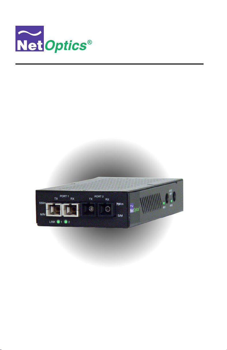
Installation Guide for
GigaBit Media Converters
800-0226-001 PUBFMCLXSXU Rev. A 12/12
Page 2

Page 3

Table of Contents
Introduction .....................................................1
Key Features ....................................................1
Product Diagram .................................................2
Connecting the GigaBit Media Converter to the Network .................3
Conguration Guidelines for Link Fault Signaling (LFS) Operation .........6
Safety Notes on Laser Singlemode and Multimode-type Converters .........7
GigaBit Ethernet Connection Distances ...............................8
GigaBit Media Converter
Specications ...................................................9
Warranty ......................................................11
Page 4

GigaBit Media Converter
PLEASE READ THESE LEGAL NOTICES CAREFULLY.
By using a Net Optics GigaBit Media Converter you agree to the terms and conditions of usage set forth
by Net Optics, Inc.
No licenses, express or implied, are granted with respect to any of the technology described in this
manual. Net Optics retains all intellectual property rights associated with the technology described in
this manual. This manual is intended to assist application in installing Net Optics products into your
network.
Trademarks and Copyrights
© 2012 by Net Optics, Inc. Net Optics® is a registered trademark of Net Optics, Inc. Additional company and product names may be trademarks or registered trademarks of the individual companies and
are respectfully acknowledged.
Additional Information
Net Optics, Inc. reserves the right to make changes in specications and other information contained
in this document without prior notice. Every effort has been made to ensure that the information in this
document is accurate.
Page 5

Introduction
Thank you for purchasing the most versatile media converter available today.
Net Optics GigaBit Media Converters enable conversion between GigaBit
Fiber signals.
Key Features
Technology
• Net Optics GigaBit Media Converters support transparent conversion of
optical signals for data rates at 1000 Mbps.
• Includes automatic Link Fault Signaling. Link Fault Signaling alerts
each host (router, switch, server) attached to a Net Optics GigaBit Media
Converter, if any of the intermediate links that separate them have failed.
If one link fails, or is not connected, the converter automatically disables
the forward link to the next device, until the unit is connected or the link is
repaired.
• Includes Clock and Data Recovery (CDR) capability for superior performance. This ensures that the overall jitter budget is not exceeded when
deploying pairs of converters.
• Fully RoHS compliant
Ease of Use
• All network connections are front-mounted for easy installation and
operation. Only the power connectors are side-mounted.
• Multiple LED indicators conrm link status.
• Compatible with all major manufacturer's network equipment.
Support
• Throughout the lifetime of your purchase, Net Optics offers free technical
support (and has done so since our start in 1996!) Our technical support
team is available from 8 am to 5 pm Pacic Time, Monday through Friday
at +1 (408) 737-7777 and via email at ts-support@netoptics.com. FAQs are
also available on Net Optics website at www.netoptics.com.
GigaBit Media Converter
1
Page 6

About this Guide
This guide covers the installation and use of the following models:
Part Number Description
FMC-LX/SX-R GigaBit Fiber Mode Converter, Rack-mount
FMC-LX/SX GigaBit Fiber Mode Converter, Stand-alone
FMC-SX/SX GigaBit Fiber Converter
GigaBit Media Converter
2
Page 7

Product Diagrams
®
MULTIMODE
Tx
Rx
SINGLEMODE
GigaBit Media Converter
+ 5VDC
1.5AMP
PWR 2
PWR 1
RxTx
SX to LX Conv ert er
LF
MM
SM
Figure 1. Rack mount model
PORT 1
TX
550m
M/M
RX
LINK
1 2
Figure 2. Stand alone model
www.netoptics.com
PORT 2
RXTX
+5VDC
+5VDC
1.5 AMP
1.5 AMP
+ 5VDC
1AMP
PWR 2
PWR 1
10 Km
S/M
3
Page 8

Connecting to the Network
1. Unpack the GigaBit Media Converter, verify that you have all components,
and obtain the required cables needed to successfully install the unit.
2. Multimode Ports: Using a duplex multimode cable, connect the appropriate
switch, server, or router to the GigaBit Media Converter's Multimode Port.
3. Singlemode Ports: Using a duplex singlemode cable, connect the appropri-
ate switch, server, or router to the GigaBit Media Converter's Singlemode
Port.
4. Supply power to the GigaBit Media Converter using the power supply
included with the unit.
5. Compare the LEDs on the Media Converter to the chart below to verify
correct setup.
• PWR: Power.
Power LED (in side of unit) illuminates green when device is
powered on.
• MM: Multimode Fiber Link.
This LED illuminates green when a good ber optic link is established.
• SM: Singlemode Fiber Link.
This LED illuminates green when a good ber optic link is established
• LF: Link Fault.
This LED illuminates yellow when a link fault is present.
GigaBit Media Converter
Note: _______________________________________________________________
The use of singlemode or multimode cabling is determined by the GigaBit
Media Converter model. The 1000BaseSX multimode ports or 1000BaseLX
singlemode ports must be connected via 50/125µm, 62.5/125µm, or
100/140µm ber.
______________________________________________________________________
4
Page 9

Connecting to the Network
When installing the GigaBit Media Converter, care must be taken in choosing
the appropriate cabling to avoid Differential Mode Delay (DMD) effects.
DMD is caused by singlemode, (1310 nanometer) laser point sources
launching into multimode cable. Optical power is concentrated in the center of
the ber core, propagating in less than 5% of possible modal paths. This can
result in reduced bandwidth and/or the appearance of individual data pulses,
refracting into multiple, overlapping, light pulses at the receiver end, causing
CRC errors.
The connection requires a Mode Conditioning patch cable to provide
the Conditioned Launch necessary to prevent (DMD) effects. Mode
Conditioning patch cables are not used with short wave length (850 nanometer) lasers. Note that ber cable is typically certied for a particular
bandwidth using light emitting diodes (LEDs) that provide the “Overlled
Launch” condition i.e. illuminate all possible modes and bers.
For additional details see the Restricted Launch Specication dened by the
Telecommunications Industry Association. The TIA FO-2.2.1 Committee
has released two standards: (1) FOTP-203: Launched Power Distribution
Measurement Procedure for Graded-Index Multimode Fiber Transmitters, and
(2) FOTP-204: Measurement of Bandwidth on Multimode Fiber.
GigaBit Media Converter
5
Page 10

550m
M/M
LINK
Duplex SC/SC
From switch, server,
or router (DTE)
Singlemode Cable
Tx
Rx
Rx
Tx
Figure 3. Connecting to the Network
GigaBit Media Converter
+ 5VDC
1AMP
PWR 2
PWR 1
PORT 1
PORT 2
TX
RXTX
RX
10 Km
1 2
S/M
Duplex SC/SC
Tx
Rx
Multimode Cable
Rx
Tx
From switch, server,
or router (DCE)
6
Page 11

GigaBit Media Converter
Conguration Guidelines for Link Fault Signaling (LFS)
Operation
Link Fault Signaling (LFS) circuitry provides visual indication of link
condition on both segments, as well as alerting each end host device when a
remote link (segment) is down. If either segment experiences a link failure,
the good segment port LED will remain lit. BUT, the Link idle signal going
to the next, remaining device on the GOOD segment, is instantly disabled,
turning off its Link LED. The converter detects the loss of link on one
segment and turns off the link signal to the next segment, even though the
second segment is intact.
The missing link signal alerts the end device(s) that a fault has occurred.
Either end can then establish an alternate connection path, using Spanning
Tree protocol. Once the original fault is corrected, all segment links are reestablished and the Link LEDs function in the normal manner.
All connections between the converter and end devices must be made before a
good end-to-end link can be established. A normal good link on both segments
will be indicated by both link LEDs lit.
At least one end device must provide a link signal to initiate a link across
all segments. If one link segment is broken, the associated link LED will no
longer be lit. The good (unbroken) segment’s link LED will remain lit and the
Link Idle signal to the next segment will turn off.
When the converter loses a link signal from either of the two devices
attached to it, the converter turns off (ceases to forward) the port link signal
to the NEXT segment (device). When the fault is corrected, all links will be
automatically re-established.
7
Page 12

GigaBit Media Converter
Safety Notes on Laser Singlemode and Multimode-type
Connectors
The FMC-LX/SX uses one 850nm laser (Multimode Port) and one 1310 nm
laser (Singlemode Port) connector.
Observe caution when deploying equipment using laser optics. Non-eye safe
laser devices may be inadvertently connected to cabling that is intended to be
attached to eye-safe 850nm or 1310 nm laser driven equipment. This poses
a risk for eye and equipment damage. All ber optic cables (connectors) that
are or may be connected to a laser source should be clearly labeled and as-
sumed to be connected to non-eye safe laser optics.
Note: _______________________________________________________________
Do not connect non-eye safe laser devices to eye-safe class equipment. Noneye safe laser driven devices, besides damaging eye sight, can permanently
damage eye-safe (low-power laser) rated equipment. Such damage will not
be covered by warranty. Net Optics, Inc. disclaims all liability for damages
arising from mis-use or incorrect installation of laser driven equipment.
______________________________________________________________________
CAUTION: NEVER ATTEMPT TO VERIFY ANY FIBER OPTIC
CONNECTION BY LOOKING DIRECTLY INTO A FIBER-OPTIC PORT
OR CABLE. IF THE LIGHT SOURCE IS A NON-EYE SAFE, LASER
EMITTER, PERMANENT EYE DAMAGE MAY RESULT.
NEVER LOOK INTO THE BORE OF A FIBER OPTIC CONNECTOR!
8
Page 13

GigaBit Ethernet Connection Distances
1000BASE-SX (850 nm laser)
GigaBit Media Converter
Fiber Core
Diameter
62.5 µm
62.5 µm Multimode 200 Mhz/km 2 to 275 m
50.0 µm Multimode 400 Mhz/km 2 to 500 m
50.0 µm Multimode 500 Mhz/km 2 to 550 m
Type
Multimode 160 Mhz/km 2 to 220 m
Fiber Bandwidth
Mhz/km
1000BASE-LX (1310 nm laser)
Fiber Core
Diameter
8.5 µm Singlemode n/a up to 10 Km
Type
Fiber Bandwidth
Mhz/km
1000BASE-ZX (1550 nm laser)
Fiber Core
Diameter
8.5 µm Singlemode n/a up to 70 Km
Type
Fiber Bandwidth
Mhz/km
Distance
Distance
Distance
9
Page 14

Specications
Environmental
Operating Temperature: 0˚C to 40˚C
Storage Temperature: -10˚C to 70˚C
Relative Humidity: 10% min, 95% max, non-condensing
Power Supply
Input: 100-240 VAC, 0.6A, 50-60 Hz
(AC100-125V~30VA, 50-60 Hz, for Japan)
Output: 5V, 2A (5V, 2.4A for UK and Japan)
Mechanical
Dimensions: 1.0” high x 5.3” deep x 2.0” wide
Connectors
(2) Duplex SC connectors
Optical Interface
Transceiver: Class I, eye-safe, laser emitter type. These Class I Lasers conform to the applicable requirements per US 21 CFR (J) and
EN 60825-1, also UL 1950 applications.
GigaBit Media Converter
Multimode:
Fiber Type: Multimode Corning 62.5µm, wavelength 850nm
Optical Transmitter Wave Length: 850 nm nominal
Output Power: -9.5 dB min, -4.0 dB max
Optical Receiver Input Sensitivity: 0.0 dB min, -18.5 dB typical, -17.0 dB max
Singlemode:
Fiber Type: Singlemode Corning 8.5µm, wavelength 1310/1550 nm
Optical Transmitter Wave Length: 1310 nm nominal
Output Power: -10.0 dB min, -3.0 dB max
Optical Receiver Input Sensitivity: -3.0 dB min, -20.0 dB max
10
Page 15

Specications
Certications
• Gigabit Ethernet series converters comply with all applicable IEEE 802.3u
specications. Net Optics’ converters are designed to comply with all the
following safety, emissions and susceptibility specications: UL 1950,
CSA-C22.2 No. 950-93, CE Mark EN60950 and EN55022, and FCC Class
A.
• Fully RoHS compliant
GigaBit Media Converter
11
Page 16

GigaBit Media Converter
Limitations on Warranty and Liability
Net Optics offers a limited warranty for all its products. IN NO EVENT SHALL NET OPTICS, INC.
BE LIABLE FOR ANY DAMAGES INCURRED BY THE USE OF THE PRODUCTS (INCLUDING BOTH HARDWARE AND SOFTWARE) DESCRIBED IN THIS MANUAL, OR BY ANY
DEFECT OR INACCURACY IN THIS MANUAL ITSELF. THIS INCLUDES BUT IS NOT LIMITED TO LOST PROFITS, LOST SAVINGS, AND ANY INCIDENTAL OR CONSEQUENTIAL
DAMAGES ARISING FROM THE USE OR INABILITY TO USE THIS PRODUCT, even if Net
Optics has been advised of the possibility of such damages. Some states do not allow the exclusion
or limitation of implied warranties or liability for incidental or consequential damages, so the above
limitation or exclusion may not apply to you.
Net Optics, Inc. warrants this GigaBit Media Converter to be in good working order for a period of
ONE YEAR from the date of purchase from Net Optics or an authorized Net Optics reseller.
Should the unit fail anytime during the said ONE YEAR period, Net Optics will, at its discretion,
repair or replace the product. This warranty is limited to defects in workmanship and materials and
does not cover damage from accident, disaster, misuse, abuse or unauthorized modications.
If you have a problem and require service, please call the number listed at the end of this section and
speak with our technical service personnel. They may provide you with an RMA number, which must
accompany any returned product. Return the product in its original shipping container (or equivalent)
insured and with proof of purchase.
THE WARRANTY AND REMEDIES SET FORTH ABOVE ARE EXCLUSIVE AND IN LIEU OF
ALL OTHERS, EXPRESS OR IMPLIED. No Net Optics reseller, agent, or employee is authorized
to make any modication, extension, or addition to this warranty.
Net Optics is always open to any comments or suggestions you may have about its products and/or
this manual.
Send correspondence to
Net Optics, Inc.
5303 Betsy Ross Drive
Santa Clara, CA 95054 USA
Telephone: +1 (408) 737-7777
Fax: +1 (408) 745-7719
Email: info@netoptics.com
Internet: www.netoptics.com
All Rights Reserved. Printed in the U.S.A. No part of this publication may be reproduced, transmitted, transcribed, stored in a retrieval system, or translated into any language or computer language,
in any form, by any means, without prior written consent of Net Optics, Inc., with the following
exceptions: Any person is authorized to store documentation on a single computer for personal use
only and that the documentation contains Net Optics’ copyright notice.
12
Page 17

Notes:
GigaBit Media Converter
13
Page 18

Notes:
GigaBit Media Converter
14
Page 19

Page 20

www.netoptics.com
© 2012 by Net Optics, Inc. All Rights Reserved.
 Loading...