

Page 1
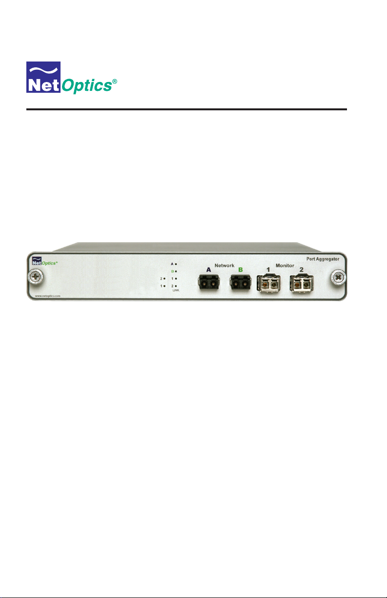
Installation Guide for
GigaBit Fiber Port Aggregator Tap
with SFP Monitor Ports
(800-0037) Doc. PUBTPASXSFPU Rev. 1, 07/08
Page 2

Page 3

Contents
Introduction . . . . . . . . . . . . . . . . . . . . . . . . . . . . . . . . . . . . . . . . . . . . . . . . . . . . . 1
Key Features . . . . . . . . . . . . . . . . . . . . . . . . . . . . . . . . . . . . . . . . . . . . . . . . . . . . 1
Unpacking and Inspection . . . . . . . . . . . . . . . . . . . . . . . . . . . . . . . . . . . . . . . . . . 3
Product Diagram . . . . . . . . . . . . . . . . . . . . . . . . . . . . . . . . . . . . . . . . . . . . . . . . . 3
LED Indicators . . . . . . . . . . . . . . . . . . . . . . . . . . . . . . . . . . . . . . . . . . . . . . . . . . 3
Application Diagrams: Memory Operation . . . . . . . . . . . . . . . . . . . . . . . . . . . . 4
Connecting to the Network . . . . . . . . . . . . . . . . . . . . . . . . . . . . . . . . . . . . . . . . . 6
GigaBit Fiber Port Aggregator Tap
Connecting the Monitoring Device . . . . . . . . . . . . . . . . . . . . . . . . . . . . . . . . . . . 7
Changing the SFP Monitor Port Connector . . . . . . . . . . . . . . . . . . . . . . . . . . . . 8
Connecting Power . . . . . . . . . . . . . . . . . . . . . . . . . . . . . . . . . . . . . . . . . . . . . . . . 8
Specications . . . . . . . . . . . . . . . . . . . . . . . . . . . . . . . . . . . . . . . . . . . . . . . . . . . 9
Accessories . . . . . . . . . . . . . . . . . . . . . . . . . . . . . . . . . . . . . . . . . . . . . . . . . . . . . 9
Limitation on Warranty and Liability . . . . . . . . . . . . . . . . . . . . . . . . . . . . . . . . 10
Page 4

GigaBit Fiber Port Aggregator Tap
PLEASE READ THESE LEGAL NOTICES CAREFULLY.
By using a Net Optics Port Aggregator Tap you agree to the terms and conditions of usage set forth
by Net Optics, Inc., the Tap manufacturer.
No licenses, express or implied, are granted with respect to any of the technology described in this
manual. Net Optics retains all intellectual property rights associated with the technology described in
this manual. This manual is intended to assist with installing Net Optics products into your network.
Trademarks and Copyrights
© 2010 by Net Optics, Inc. Net Optics® is a registered trademark of Net Optics, Inc. Additional company and product names may be trademarks or registered trademarks of the individual companies and
are respectfully acknowledged.
Additional Information
Net Optics, Inc. reserves the right to make changes in specications and other information contained
in this document without prior notice. Every effort has been made to ensure that the information in
this document is accurate.
Page 5

Introduction
Net Optics GigaBit Port Aggregator Taps with SFP Monitor Ports provide
ultra-efcient access to critical GigaBit links. This pioneering technology enables any two devices to simultaneously monitor a full-duplex link using only
one NIC per monitoring device. Small Form Factor Pluggable (SFP) connectors on the Monitor Ports allow these Port Aggregators to also perform media
conversion from ber to copper.
Typically, full-duplex monitoring with a network tap requires two NICs (or
a dual channel NIC) – one interface for each side of the tapped full-duplex
connection. The Gigabit Port Aggregator Tap combines and regenerates these
streams, sending all aggregated data out one or two passive monitoring ports.
The best part of this innovation is the onboard memory that ensures trafc
isn't dropped during bursts.
The GigaBit Port Aggregator Tap is designed to handle the combined trafc of
a single full-duplex link. Normally, the trafc should be below the receiving
capacity of the NIC, that is, less than 1 Gbps.
When the trafc queue exceeds the capacity of the NIC, the Tap buffers the
overow up to 1GB. The buffers clear automatically when the trafc volume
falls below the receiving capacity of the NIC. For example, if there is a trafc
burst and a Tap connected to a 1 Gbps network port on a monitoring device is
now receiving 1.2 Gbps of trafc, the Tap buffers data until the burst is over.
The Tap then sends the buffered data to the monitoring device until the buffer
is cleared.
GigaBit Fiber Port Aggregator Tap
Key Features
Technology
• Supports full-duplex monitoring with a single NIC, increasing monitoring
efciency
• Regeneration Tap technology enables two devices to simultaneously moni-
tor all aggregated trafc – using only one NIC per device
• 1GB of buffer memory prevents data loss during excessive trafc loads
• Provides complete full-duplex visibility at 1 Gbps without data stream
interference or introducing a point of failure
1
Page 6

GigaBit Fiber Port Aggregator Tap
• Passes all trafc (including errors) from all layers for comprehensive
troubleshooting
• No IP address is needed for the Tap or monitoring device, enhancing monitoring security
• Redundant power ensures monitoring uptime
• Fully RoHS compliant
Ease of Use
• LED indicators show redundant power, speed, link, and activity status
• Front-mounted connectors support easy installation and operation
• Silk-screened application diagram illustrates all connections for easy
deployment
• Optional 19-inch rack frames hold up to two Taps
• Small form-factor pluggable (SFP) monitor port connectors increase
monitoring options
• Tested and compatible with all major manufacturers’ monitoring devices,
including protocol analyzers, probes, and intrusion detection/prevention
systems
Support
• Net Optics offers free technical support throughout the lifetime of your
purchase (and has done so since our start in 1996!). Our technical support
team is available from 8 am to 5 pm Pacic Time, Monday through Friday
at +1 (408) 737-7777 and via email at ts-support@netoptics.com. FAQs are
also available on Net Optics website at www.netoptics.com.
Unpacking and Inspection
Carefully unpack the GigaBit Fiber Port Aggregator Tap and check for damaged or missing parts. The Port Aggregator Tap ships with the following:
• GigaBit Fiber Port Aggregator Tap with SFP Monitor Ports
• Two SC to SC ber cables
• Two power supplies (AC power models)
• Installation Guide
In addition to the Port Aggregator, you should have ordered one or two GigaBit SFP modules. You may have also ordered an extended warranty. Carefully
check the packing slip against parts received. If any part is missing or damaged, contact Net Optics' Customer Service immediately.
2
Page 7
About this Guide
This Guide provides you all the information you need to install and operate
the GigaBit Fiber Port Aggregator Tap. Please read the entire Guide before
attempting to install or operate the Tap.
This Guide covers the following models:
Part Number Description
TPA-SX4-SFP GigaBit Port Aggregator, multimode SX ber, 60/40 split
TPA-SX5-SFP GigaBit Port Aggregator, multimode SX ber, 50/50 split
TPA-LX4-SFP GigaBit Port Aggregator, singlemode LX ber, 60/40 split
TPA-LX5-SFP GigaBit Port Aggregator, singlemode SX ber, 50/50 split
TPA-50SX5-SFP GigaBit Port Aggregator, multimode 50um SX ber,
GigaBit Fiber Port Aggregator Tap
ratio, two SPF monitor ports
ratio, two SPF monitor ports
ratio, two SPF monitor ports
ratio, two SPF monitor ports
50/50 split ratio, two SPF monitor ports
www.netoptics.com
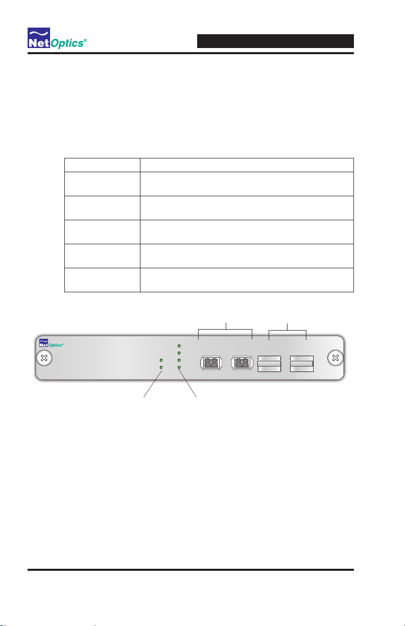
Product Diagram
Figure 4: Front Panel
LED Indicators
• PWR 1/ PWR 2: Main and Redundant Power. If the Tap is deployed with
both power supplies, both LEDs illuminate when the Tap is plugged in. If
an LED is off, this indicates that the corresponding power supply is not
functioning.
• Link/Activity Indicators: If a good link is established, the LED illu-
minates a steady green. If there is current activity on this link, the LED
ashes.
Power LEDs
Network Ports
A
B
1
2
2
1
LINK
Network Monitor
A B
Link LEDs
Monitor Ports
with plugs
1
Port Aggregator
2
3
Page 8

GigaBit Fiber Port Aggregator Tap
Using a single NIC, the monitoring
device receives all combined traffic
Application Diagrams: Memory Operation
All trafc that passes through the Tap is sent to the monitoring device NIC on
a rst-in, rst-out basis, including trafc that is temporarily stored in memory.
(If two packets enter at the same time then one packet is processed while the
other is stored briey in memory, preventing collisions.)
When there is a burst of data, trafc in excess of the NIC's capacity is sent to
the Tap's memory. Up to 512 megabytes of data per side of the full-duplex
stream can be stored in memory. Memory continues to ll until its capacity is
reached, or the burst ends – whichever comes rst.
In both cases, the Tap applies a rst-in, rst out procedure, processing stored
data before new data from the link. If memory lls before the burst ends, the
memory stays lled as the stored data is processed – data that leaves the buffer
is immediately replaced. If the burst ends before the memory lls, memory
clears until the full megabyte of capacity is available, or another until another
burst in excess of the NIC's capacity requires additional memory.
The following three diagrams illustrate a simple example of a 1000 Mbps NIC
moving from 80% utilization, to 140% utilization, then back to 80%
utilization.
State 1: Side A + Side B is less than or equal to 100%
of the NIC's receive capacity.
Example: On a 1000 Mbps Span port, Side A is at 300 Mbps and Side B is at 500 Mbps.
The NIC receives 800 Mbps of traffic (80% utilization), so no memory is required
for the monitoring device NIC to process all full-duplex traffic.
Side A Side B
Span Port 1
Figure 1: Aggregated trafc is less than NIC's capacity
GigaBit SX SFP
Port Aggregator Tap
Network
A B
Network Monitor
1 2
1
2
A
B
OUT IN OUT IN
Side A +
Side B
Monitoring Device
4
Port Aggregator
Span Port 2
1
from Side A and Side B, including
physical layer errors.
Page 9

GigaBit Fiber Port Aggregator Tap
State 2: Side A + Side B becomes greater than 100%
of the NIC's receive capacity.
Example: There is a burst of traffic, so Side A is now at 900 Mbps while
Side B remains at 500 Mbps. The NIC's utilization is at 140%, requiring
the use of memory to help prevent data loss.
The extra 400 Mbps of traffic is
stored in the 512 megabyte buffer
for Port A. Memory continues to
fill until the 512 megabyte capacity
is reached, or the burst ends.
(A separate 512 megabyte buffer is
also available to handle a burst
on Port B.)
Side A Side B
Span Port 1
Memory
2
GigaBit SX SFP
Port Aggregator Tap
Network
Network Monitor
A B
1
A
B
1 2
OUT IN OUT IN
Side A +
Side B
Monitoring Device
Port Aggregator
2
1
Using a single NIC, the monitoring
device receives 1000 Mbps of combined
traffic from Side A and Side B, including
physical layer errors.
Figure 2: Aggregated trafc is greater than NIC's capacity
State 3: Side A + Side B is once again less than 100%
of the NIC's receive capacity.
Example: On a 1000 Mbps link, Side A is again at 300 Mbps and Side B
remains at 500 Mbps. The NIC's utilization is again at 80%.
Side A Side B
Sapn Port 1
GigaBit SX SFP
Port Aggregator Tap
Network Monitor
Network
A B
1
A
B
1 2
OUT IN OUT IN
Port Aggregator
2
Span Port 2
Span Port 2
Memory
The Tap applies a first-in, first-out
process to all packets. Once the burst
has ended and the NIC's utilization is
again below 100 percent, the Tap first
processes the packets that were stored
in memory. As long as the NICʼs
utilization remains below 100 percent,
this process continues uninterrupted
until the memory clears.
1
Figure 3: Trafc burst has passed
Monitoring Device
5
2
Once the memory has cleared, the
monitoring device begins receiving
Side A +
new data directly from the link. Using
Side B
a single NIC, the monitoring device
receives all traffic from Side A and
Side B, including physical layer errors.
Page 10

Connecting to the Network
Optical connections are extremely sensitive to contaminants. Make sure all
optical surfaces are clean before connecting.
To connect to the Network Ports:
1. Remove protective plugs.
2. Connect Network Port A to the appropriate network device using a Duplex
LC cable.
3. Connect Network Port B to the appropriate network device using a Duplex
LC cable.
4. Verify that the Tap Network Ports are cabled in-line between two devices.
GigaBit Fiber Port Aggregator Tap
2
www.netoptics.com
1
To Span Port
Figure 4: Connecting to the Network
A
B
1
2
LINK
Network Monitor
A B
1
Port Aggregator
2
To Span Port
6
Page 11
GigaBit Fiber Port Aggregator Tap
TX
TX RX
TX
TX RX
Application Illustration
Network
B 1 2A
Monitor
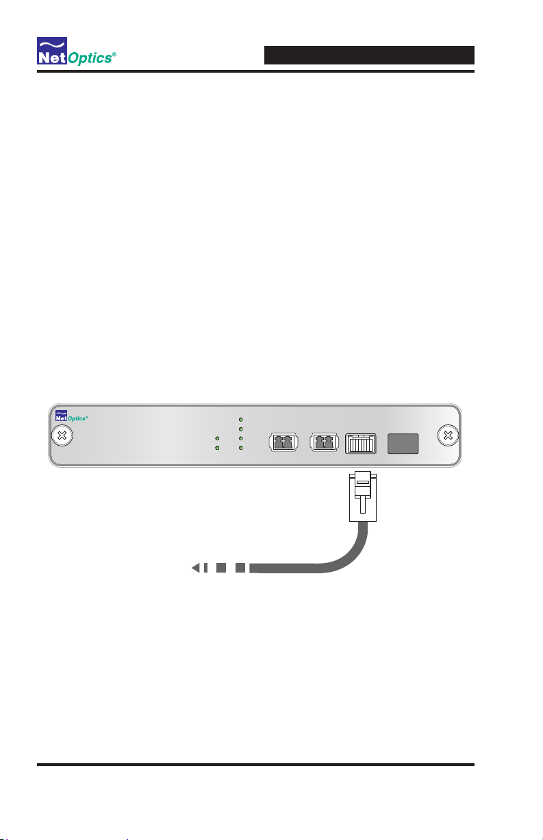
Connecting the Monitoring Device
To protect the Port Aggregator Tap, the SFP slots are lled with temporary
plugs. If you are installing only one SFP, leave the plug in Monitor Port 2 to
protect the Port Aggregator Tap. You must install the SFP before connecting to
the monitoring device.
To connect the Monitor Ports:
1. Remove the SFP from its protective packaging.
2. Remove the temporary plug from Monitor Port 1.
3. Insert the SFP in the Monitor 1 Port until you hear it click into place.
4. Connect Monitoring Port 1 to the appropriate port on the monitoring
device using an RJ45 CAT5e cable to monitor the
5. If you are installing two SFPs, repeat Steps 1 through 4 for Monitor Port 2.
A and B links.
A
B
1
2
2
1
www.netoptics.com
LINK
To Monitoring Device
Figure 5: Connecting the Monitoring Device
7
Network Monitor
A B
1
Port Aggregator
2
Page 12

GigaBit Fiber Port Aggregator Tap
Changing the SFP Monitor Port Connector
You have the option to change the interface on the Monitor Port by changing
the small form-factor plug (SFP) on the Monitor Port. You can order conver-
sion kits which include the singlemode ber, multimode ber, GigaBit copper
SFP and appropriate cable from Net Optics. For ordering information, see
Specications on page 9.
To change the SFP:
1. Remove the cable from the SFP on the Port Aggregator Tap.
2. Lower the wire clip to release the SFP connector.
3. With the clip on the lowered position, pull gently on the clip to free the
SFP.
4. Insert the new SFP until you hear it click into place.
5. Connect the cable supplied with the kit.
Connecting Power
The second power supply is available to support the ow of trafc to the
monitoring device, in the event that the rst power supply becomes unavailable. If the rst power supply is unavailable, the second power supply will
supply all power for the Tap. Even if no power is available to the passive Tap,
network trafc ows uninterrupted.
1. Supply power to the Tap via the two power connectors on the rear of the
unit. Two power supplies are included with the AC power models. The use
of the second redundant power supply is optional.
2. Verify that the Power LEDs illuminate. PWR 1 illuminates when the rst
power supply is in use, and PWR 2 illuminates when the second power
supply is in use. Both power supplies can be plugged into the Tap at the
same time.
8
Page 13

Specications
Optical
SX Fiber Type: Corning Multimode 50/125µm or 62.5/125µm, wavelength
850nm
LX Fiber Type: Corning Multimode 8.5/125µm, wavelength 1310nm
Environment
Operating Temperature: 0˚C to 40˚C
Storage Temperature: -10˚C to 70˚C
Relative Humidity: 10% min, 95% max, non-condensing
Power
AC Power Input: 100-240 VAC, 0.5A, 47-63Hz
Output: 12V, 3A
Mechanical
Dimensions: 1.125” high x 11” deep x 8.75” wide
Connectors
(2) Duplex LC connectors (network ports)
(2) SFP ports for SFP modular connectors
GigaBit Fiber Port Aggregator Tap
Certications
Fully RoHS compliant
Accessories
SFP Conversion Kits
SFPKT-SX Multimode ber SFP with cable
SFPKT-LX Singlemode ber SFP with cable
SFPKT-CU3 Triple-speed copper SFP with cable
9
Page 14

GigaBit Fiber Port Aggregator Tap
Limitation on Warranty and Liability
Net Optics offers a limited warranty for all its products. IN NO EVENT SHALL NET OPTICS,
INC. BE LIABLE FOR ANY DAMAGES INCURRED BY THE USE OF THE PRODUCTS
(INCLUDING BOTH HARDWARE AND SOFTWARE) DESCRIBED IN THIS MANUAL, OR
BY ANY DEFECT OR INACCURACY IN THIS MANUAL ITSELF. THIS INCLUDES BUT IS
NOT LIMITED TO LOST PROFITS, LOST SAVINGS, AND ANY INCIDENTAL OR CONSEQUENTIAL DAMAGES ARISING FROM THE USE OR INABILITY TO USE THIS PRODUCT, even if Net Optics has been advised of the possibility of such damages. Some states do not
allow the exclusion or limitation of implied warranties or liability for incidental or consequential
damages, so the above limitation or exclusion may not apply to you.
Net Optics, Inc. warrants this Tap to be in good working order for a period of ONE YEAR from the
date of purchase from Net Optics or an authorized Net Optics reseller.
Should the unit fail anytime during the said ONE YEAR period, Net Optics will, at its discretion,
repair or replace the product. This warranty is limited to defects in workmanship and materials and
does not cover damage from accident, disaster, misuse, abuse or unauthorized modications.
If you have a problem and require service, please call the number at the end of this section to speak
with our technical service personnel. They may provide you with an RMA number, which must
accompany any returned product. Return the product in its original shipping container (or equivalent) insured and with proof of purchase.
THE WARRANTY AND REMEDIES SET FORTH ABOVE ARE EXCLUSIVE AND IN LIEU
OF ALL OTHERS, EXPRESS OR IMPLIED. No Net Optics reseller, agent, or employee is autho-
rized to make any modication, extension, or addition to this warranty.
Net Optics is always open to any comments or suggestions you may have about its products and/or
this manual.
Send correspondence to
Net Optics, Inc.
5303 Betsy Ross Drive
Santa Clara, CA 95054 USA
Telephone: +1 (408) 737-7777
Fax: +1 (408) 745-7719
Email: info@netoptics.com/Internet: www.netoptics.com
All Rights Reserved. Printed in the U.S.A. No part of this publication may be reproduced, transmitted, transcribed, stored in a retrieval system, or translated into any language or computer language,
in any form, by any means, without prior written consent of Net Optics, Inc., with the following
exceptions: Any person is authorized to store documentation on a single computer for personal use
only and that the documentation contains Net Optics' copyright notice.
10
Page 15

Page 16

www.netoptics.com
© 2010 by Net Optics, Inc. All Rights Reserved.
 Loading...