

Page 1
Director™ Data Monitoring Switch
Director Pro™ Network Controller Switch
Quick Install Guide
Version 7.6
Introduction
This document provides the initial steps to congure both the Director
and Director Pro appliances. For more information on the two appliances,
refer to the Director User Guide and Director Web Guide located on the CD.
In this guide, both Director and Director Pro are referred to as Director.
Unpack and Inspect
Carefully unpack Director and review the following components. Retain
the packing material for later use. Contact Net Optics customer service if
any component is missing or damaged.
• Director or Director Pro unit
• Two Power cords
• Two Cables, 3 Meter, RJ45, CAT 5e 4-pair (purple)
• Cable, RJ45-DB9, for console port connection
• Rack mounting Kit
• Two 10-32 x 5/8” screws and washers (for rack mounting)
• Director and Director Pro Quick Install Guide (this guide)
• CD containing the Director and Director Pro User Guide, Director and
Director Pro CLI Command Reference, and Director and Director Pro Web UI
User Guide
• Registration instructions
• Service Plan Reference Guide
• Extended Warranty, if an extended warranty is purchased
XFP and SFP modules are ordered and shipped separately.
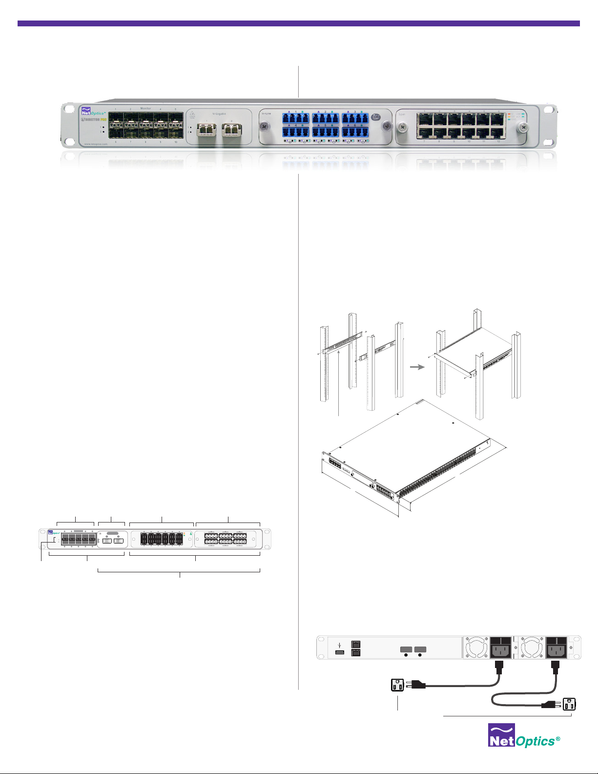
Director
www.netoptics.com
™
1
2
10 SFP
Monitor
Ports
Monitor
1 2 54
6 7 8
Monitor PortsPower LEDs
9
Configurable
10GbE Ports
LASER
CAUTION!
1
2
10
2 XFP
10G
1 2
DNM with 10/100/1000
Copper Network Ports
(6 In-line or 12 Span Ports)
1 2 3 4 5 6
Span
10 11 12
7 8 9
2 Director Network Module (DNM) Slots
Network Ports
DNM with SX Fiber
Network Ports
(6 In-line or 12 Span Ports)
1 2 3
AABBAABBAAB
10
LINK
In-Line
ACT
100
1000
4 5 6
B
DIR-7400 Model
Plan the Installation
Determine an IP address to assign to the device Management port. If
you access Director through a gateway, determine the network gateway
address and subnet mask before beginning the installation.
Restricted Access Location (RAL)
Net Optics recommends installing Director in a Restricted Access Location
(RAL) for locations with unreliable earthing or for customers with security
concerns, since only trained service personnel can access equipment
located in a RAL.
Rack Mount the Director Device
Director is designed for rack mounting in a 19-inch equipment rack and
occupies one rack unit.
1. Expand the mounting rails to t the depth of your rack. See (A).
2. Attach the mounting rails to the front and rear pillars of the rack using
the supplied screws. The rail shelves that the Director chassis will sit on
should be located along the bottom of the rails.
3. Slide the chassis into the rack so it rests on the rail shelves. See (B).
4. Fasten the chassis with the supplied screws at the front panel ears.
5. Make sure the rack is properly grounded.
(A)
(B)
Rail shelves along bottom
23.73
19.0
1.72
Connect to AC Power
1. Install a power supply cord restraint clip over it to keep the AC power
cord from unplugging from the AC power connector.
2. Connect an AC power cord to the AC power connectors.
3. Plug the other end of the cord into an AC power circuit.
4. For redundant power, connect the other AC power cord to the other
AC power connector on the rear panel and plug the other end of the
cord into a dierent AC power source.
Management Port
Console Port
USB
AC Models
Independent Power Sources
3 4
10G
1 0 1 0
© 2013 by Net Optics, Inc. Net Optics® is a registered trademark of Net Optics, Inc. Director™ and Director Pro™ are trademark of Net Optics, Inc. 800-0038-002 Rev. E 09/13
Page 2
To network switch or hub
4
1 0 1 0
Management
Port
Console
Port
10G
Connect to DC Power
1 0 1 0
Management
Port
Console
Port
10G
Independent Power Sources
For DC powered models, you must supply your own power cables. DC
power cables must have a wire gauge of at least 16 AWG and a 72 VDC,
6A rating. You need a Phillips screwdriver to complete installation. If
present, remove the protective covers from the DC power terminal
blocks. Use the Phillips screwdriver to tighten the connections.
Caution: Always connect the earth electrical grounds rst, and keep the
earth grounds connected whenever you are working on the device.
Management
Port
Console
Port
Power Source 1
Power Source 2
Earth
Ground
-48VDC
Return
-48VDC
Return
-
+
10G
For use with -48V Only
For use with -48V Only
-
+
1. Connect an earth ground lead to the terminal labeled with the ground
symbol ( ), which is the left-most terminal, on both DC power terminal
blocks on the rear of the chassis.
2. Connect Power Source 1 DC power cables to the DC power terminal
blocks on the rear panel.
3. Connect the negative (– 48VDC) side of the cable to a terminal labeled
with the minus symbol (–), and the positive (0V) side of the cable to the
terminal labeled with the plus symbol (+). The negative (minus symbol)
terminal is in the center, and the plus terminal is to the right.
4. Connect Power Source 2 DC power cables to the DC power terminal
blocks on the rear panel.
5. Connect the negative (– 48VDC) side of the cable to the terminal
labeled with the minus symbol (–), and the positive (0V) side of the
cable to the terminal labeled with the plus symbol (+).
6. Carefully connect the other two – 48VDC ends of the DC power cables
to two negative (– 48VDC) power sources.
Caution: If possible, turn o the power to the power sources while you
are making the following connections.
7. Connect the other two + 48VDC ends of the DC power cables to two
positive (+ 48VDC) power sources.
Note: Be sure to connect the positive side of a cable to the positive side
of the power source, and the negative side of the power cable to the
negative side of the power source.
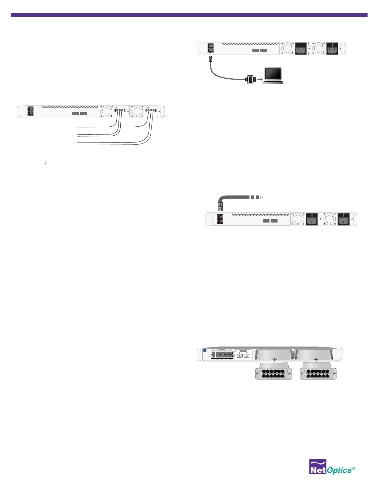
Congure Director
All conguration options, status, and statistics are congurable and
viewable using the command-line interface (CLI). To get started with the
Director, connect a console to the Director device console port interface
to access the CLI. Through the local CLI, set the Management port IP
address to enable remote access to the device.
Management
Port
Console
Port
Cisco DB9 to RJ45
Console Cable
10G
Computer with terminal
emulation software
1 0 1 0
5. Set the Director IP address by typing: sysip set ipaddr=<ipaddress>
mask=<netmask> gw=<gateway> sysip commit where <ip
address> is the IP address for Director, <netmask> is the netmask, and
<gateway> is the IP address of the gateway
6. For more information on the CLI, type Help to display command
information, or see the CLI Reference manual.
7. Use Tab to auto-complete partially typed commands. Enter ? following a
command (and a space) displays the arguments for that command.
The up- and down-arrow keys access the CLI command history buer.
To access via SSH:
1. Connect the Management port with a CAT 5e cable to a switch/hub.
2. In a terminal window of a PC connected to the network, at the
prompt, type: ssh admin@<IP_address>.
3. Enter the password, netoptics. The Net Optics banner displays.
4. Log into Director with the default username admin and password
netoptics if no other accounts have been added.
Connect to the Network
If the Director Network Modules (DNMs) are not already installed
when you receive the unit, install them by sliding them carefully into
the DNM slots in the front panel.
To install DNMs:
1. Remove the cover plate from Slot 1 (if present) by unscrewing the two
thumbscrews.
Monitor
Director
www.netoptics.com
™
1
2
www.netoptics.com
1 2 54
2
1
6 7 8
1
B
2
10
9
7 8 9
Slot 1
10 11 12
1 2 3 4 5 6
Span
10G
LASER
CAUTION!
A B
1 2
A
10
LINK
ACT
100
1000
1 2 3
AABBAABBAAB
In-Line
4 5 6
Slot 2
10
LINK
ACT
100
1000
B
To access the Command Line Interface:
1. Connect a PC with terminal emulation software to the Director device
Console port using the supplied DB9 to RJ45 cable.
2. Launch the terminal emulation software such as
HyperTerminal or minicom and set the communication parameters:
115200 baud, 8 data bits, no parity, 1 stop bit, no ow control.
3. At the login prompt, type admin, and at the password prompt, type
netoptics.
4. Enter a new password for the admin account.
© 2013 by Net Optics, Inc. Net Optics® is a registered trademark of Net Optics, Inc. Director™ and Director Pro™ are trademark of Net Optics, Inc. 800-0038-002 Rev. E 09/13
2. Slide the DNM into Slot 1 with the DNM circuit boards riding in the
rails.
3. Push in the DNM rmly until you feel the connectors mate and the
bezel is ush with the front panel.
4. Secure the DNM with the two captured thumbscrews.
5. Repeat for Slot 2 if installing two DNMs.
Warning! Use caution when installing the DNM into the chassis
to prevent damage to any components on the bottom side.
Page 3

To connect Director to a Span port on your network:
10
100
1000
LINK
ACT
In-Line
10
100
1000
LINK
ACT
AABBAABBAAB
B
1 2 3
4 5 6
Create a Filter
1. Connect any network port on a Span DNM to an
appropriate network cable.
Monitor
Director
www.netoptics.com
™
1
2
1 2 54
6 7 8
1 2 3 4 5 6
Span
10G
LASER
CAUTION!
1 2
1
2
10
9
7 8 9
10 11 12
10
LINK
ACT
100
1000
To Span port
1 2 3
AABBAABBAAB
In-Line
4 5 6
10
LINK
ACT
100
1000
B
2. Connect the other end of the cable to a Span port on a network
switch.
To connect Director in-line to your network:
1. Connect any “A” network port on an in-line DNM to a network
cable.
2. Connect the other end to a network link you are tapping.
3. Connect the corresponding “B” network port to an appropriate
network cable. In-line port pairs are located side-by-side in the
DNMs.
4. Connect the other end to the other side of the network link you
are tapping.
Monitor
Director
www.netoptics.com
™
1
2
1 2 54
6 7 8
1 2 3 4 5 6
Span
10G
LASER
CAUTION!
1 2
1
2
10
9
10 11 12
7 8 9
To network switch A To network switch B
10
LINK
ACT
100
1000
1 2 3
AABBAABBAAB
In-Line
4 5 6
10
LINK
ACT
100
1000
B
Connect to Monitoring Devices
1. Remove the temporary plug from the monitor slot and insert the
SFP module until it clicks into place.
2. Connect the cable supplied with the SFP module to the SFP port.
3. Connect the other end of the cable to the monitoring device.
Monitor
Director
www.netoptics.com
™
1
2
1 2 54
6 7 8
10
9
10G
LASER
CAUTION!
1 2
1
2
To monitoring device
Connect to 10 Gigabit Ports
Each of the 10 Gigabit ports (two on the front of the chassis of
DIR-7400 and DIR-6400p, and two on the rear of DIR-7400 and DIR5400, one rear port for DIR-6400p), can be connected as network
or monitor ports. These ports require XFP modules (ordered and
shipped separately). The function of the port, as network or monitor, is
determined by how you congure the port.
1 2 3 4 5 6
Span
7 8 9
10 11 12
To view trac on monitor ports, you must dene one or more lters.
For example, create a lter that:
• Aggregates trac received on network ports 1 to 5 and 7
• Drops any trac originating from 10.1.1.1
• Forwards only Layer 4 trac going to Port 80
• Regenerates it to monitor ports 1 and 2
To create the lter, enter the three following commands using the
CLI:
Net Optics> lter add in_ports=n1.1-n1.5,n1.7 ip4_src=10.1.1.1
action=drop
Net Optics> lter add in_ports=n1.1-n1.5,n1.7 l4_dst_port=80
action=redir redir_ports=m.1-m.2
Net Optics> lter commit
For more information, see the Director and Director Pro User Guide
included on the Director CD.
Daisy Chain Director Units
Daisy chaining (or stacking) is the process of creating a single,
logical multi-unit system from many systems.
• DIR-7400, DIR-5400 and DIR-6400p support daisy chaining.
• DIR-6400p can only be used as a master unit and/or the slave unit
of the chain.
• Up to ten units can be daisy chained in one multi-unit system.
• All units in the system must be running the same version of the
Director software.
• All units must have their own IP address and be connected to the
network.
• All units must be interconnected in a daisy chain conguration by
cabling port t2.2 (rear right 10G port) of the Master unit to port
t2.1 (rear left 10G port) on the next unit. Ports t2.1 on the rst unit
in the daisy chain and t2.2 in the last unit are unused (they cannot
be used as network or monitor ports.)
• Once systems are operating in a daisy chain, all management
(CLI, Web Manager, and System Manager) functions operate
through the master unit. If a remote unit’s device management
functions are accessed through the remote unit’s serial port or
management IP address, the results are unpredictable.
• All units are assigned Unit ID (UID) numbers consecutively
starting with 1. The UID 1 is at the beginning of the daisy chain
and is the master unit; the rest are slave or remote units.
Check the Installation
After you have made your connections to the Director, verify that it
is functioning correctly:
• Check that the power LEDs are illuminated.
• Check the link LEDs for each of the connected ports to verify that
the links are connected and trac is present.
© 2013 by Net Optics, Inc. Net Optics® is a registered trademark of Net Optics, Inc. Director™ and Director Pro™ are trademark of Net Optics, Inc. 800-0038-002 Rev. E 09/13
Page 4

Director Models
The following table displays all models of Director/Director Pro and a
concise description of what ports each model has. Only the stacking
ports can be used for daisy chaining the units.
Part # Description
DIR-3400 Director Main Chassis with 10 SFP
monitor ports
DIR-5400 Director Main Chassis with SFP
monitor ports, 2 rear 10 Gbps XFP
(can be used for stacking) ports
DIR-7400 Director Main Chassis with 10 SFP
monitor ports, 2 front XFP 10 Gbps
ports, 2 rear 10 Gbps XFP (can be
used for stacking) ports
DIR-6400p Director Pro Main Chassis with 10
SFP monitor ports, 2 front XFP 10
Gbps ports, 1 rear 10 Gbps XFP
(can be used for stacking) port.
Front
10G
Ports
0 0
0 2
2 2
2 1
Rear 10G
Stacking
Ports
Connect the Daisy Chain
1. Power o all units.
2. Connect the daisy chain cables between them as shown in the
following diagram.
3. Power up the units and ensure all devices are reachable via the
network.
Master Unit
Management
Port
Console
Port
Management
Port
Console
Port
t2.1
10G
4
t2.2
10G
4
t2.2
1 0 1 0
1 0 1 0
Congure the Daisy Chain
After connecting all the units for the multi-unit system, do the
following to congure them for master and slaves.
To set the Slave units:
1. SSH and log into the second and following units of the chain and
congure each to be a Slave unit.
2. Enter remote set admin=enable master=disable. The
conguration of the master unit is pending.
3. Enter remote commit.
To set the Master unit:
1. Log into the rst unit and congure it to be the Master unit Enter
remote set admin=enable master=enable.
2. Enter remote group topology=1,2,3,4,... Include numbers
for as many units that are in the stack, such as remote group
topology=1,2 for a two-unit system. (The UID list cannot contain
spaces. )
3. Enter remote show. The pending conguration is displayed.
4. Enter remote commit. The master unit initializes the slave units with
the conguration routing information.
5. Enter remote show. Verify that the running conguration is correct
and all units are Up.
Customer Support
If you have questions while your product is under Net Optics Warranty
or you are enrolled in a support plan, please contact the Net Optics
Technical Assurance Center (TAC) via e-mail at support@netoptics.
com or by calling +1.408.737.7777, Monday through Friday, between
the following hours in your region:
• 7:00 - 17:30 Americas (Pacic Time)
• 9:00 - 17:00 EMEA (Frankfurt)
• 9:00 - 17:00 APAC (Hong Kong Time)
Management
Port
Console
Port
10G
4
1 0 1 0
t2.2
t2.1
t2.1
Management
Port
Console
Port
© 2013 by Net Optics, Inc. Net Optics® is a registered trademark of Net Optics, Inc. Director™ and Director Pro™ are trademark of Net Optics, Inc. 800-0038-002 Rev. E 09/13
10G
4
1 0 1 0
 Loading...