

Page 1
Installation Guide for
10/100 to Triple-speed Port Aggregator
Model TPA-CU
In- Lin e
800-0045-001 Doc. PUBTPACUU Rev. 1, 12/08
Page 2

Page 3

Contents
Introduction . . . . . . . . . . . . . . . . . . . . . . . . . . . . . . . . . . . . . . . . . . . . . . . . . . . . . 1
Key Features . . . . . . . . . . . . . . . . . . . . . . . . . . . . . . . . . . . . . . . . . . . . . . . . . . . . 3
About This Guide . . . . . . . . . . . . . . . . . . . . . . . . . . . . . . . . . . . . . . . . . . . . . . . . 4
Unpacking and Inspection . . . . . . . . . . . . . . . . . . . . . . . . . . . . . . . . . . . . . . . . . . 4
Product Diagrams . . . . . . . . . . . . . . . . . . . . . . . . . . . . . . . . . . . . . . . . . . . . . . . . 5
LED Indicators . . . . . . . . . . . . . . . . . . . . . . . . . . . . . . . . . . . . . . . . . . . . . . . . . . 5
Application Diagrams: Memory Operation . . . . . . . . . . . . . . . . . . . . . . . . . . . . 6
10/100 to Triple-speed Port Aggregator
Cabling Guidelines . . . . . . . . . . . . . . . . . . . . . . . . . . . . . . . . . . . . . . . . . . . . . . . 8
Connecting to the Network . . . . . . . . . . . . . . . . . . . . . . . . . . . . . . . . . . . . . . . . . 8
Connecting to the Monitoring Devices . . . . . . . . . . . . . . . . . . . . . . . . . . . . . . . . 9
Specications . . . . . . . . . . . . . . . . . . . . . . . . . . . . . . . . . . . . . . . . . . . . . . . . . . 10
Limitations on Warranty and Liability . . . . . . . . . . . . . . . . . . . . . . . . . . . . . . . 11
Page 4

10/100 to Triple-speed Port Aggregator
PLEASE READ THESE LEGAL NOTICES CAREFULLY.
By using a Net Optics Tap you agree to the terms and conditions of usage set forth by Net Optics, Inc.
No licenses, express or implied, are granted with respect to any of the technology described in this
manual. Net Optics retains all intellectual property rights associated with the technology described in
this manual. This manual is intended to assist with installing Net Optics products into your network.
Trademarks and Copyrights
© 2010 by Net Optics, Inc. Zero DelayTM Net Optics® is a registered trademark of Net Optics, Inc.
Additional company and product names may be trademarks or registered trademarks of the individual
companies and are respectfully acknowledged.
Additional Information
Net Optics, Inc. reserves the right to make changes in specications and other information contained
in this document without prior notice. Every effort has been made to ensure that the information in this
document is accurate.
Page 5

Introduction
Net Optics 10/100 to Triple-speed Port Aggregator provides ultra-efcient
access to critical links. This pioneering technology enables any monitoring
device to simultaneously monitor a full-duplex link - using only one NIC per
device.
Typically, full-duplex monitoring with a network tap requires two NICs (or
a dual channel NIC) – one interface for each side of the tapped full-duplex
connection. The Port Aggregator Tap combines and regenerates these streams,
sending all aggregated data out two separate passive monitoring ports.
Triple-Speed Monitoring Ports
The 10/100 to Triple-speed Port Aggregator features triple-speed 10/100/1000
ports for monitoring tools, enabling faster tools to capture both sides of a
fully-utilized 100 Mbps full-duplex link without relying on the Tap's buffering
capability.
Buffering Prevents Lost Data
The 10/100 to Triple-speed Port Aggregator is designed to handle the com-
bined trafc of a single full-duplex link. When the trafc queue exceeds the
capacity of a 10 or 100 Mbps NIC, the Tap buffers the overow of up to one
gigabyte of data for both sides of the full-duplex connection. The buffer clears
automatically when the trafc volume falls below the receiving capacity of the
NIC. For example, if there is a trafc burst on a 100 Mbps network port and
a 100 Mbps monitoring device is now receiving 140 Mbps of trafc, the Tap
buffers data until the burst is over. The Tap then sends the buffered data to the
monitoring device until the buffer is cleared.
10/100 to Triple-speed Port Aggregator
Simple to Deploy
The Net Optics 10/100 to Triple-speed Port Aggregator is a simple plug-andplay solution addressing the fact that many monitoring systems, including
most software-based solutions, only offer a single channel NIC, limiting fullduplex visibility. While adding a second NIC can help maintain data integrity
and visibility, there is a trade-off in exibility and ease-of-use. An operating
system and NICs that enable binding are often required to achieve the same
functionality as the Port Aggregator Tap. In contrast, the Port Aggregator Tap
requires no additional components or conguration on the monitoring devices.
1
Page 6

10/100 to Triple-speed Port Aggregator
Better than Span Ports
In the past, Span ports were occasionally used to aggregate tapped trafc.
However, in addition to other shortcomings of Span port monitoring, Span
ports support very limited buffering and can simply drop data during bursts.
The generous buffers of the Port Aggregator Tap prevent data loss in these
conditions.
TM
Zero Delay
- A Net Optics Breakthrough
Highly sensitive network locations can improve monitoring performance via
the innovative features of Net Optics Taps. If power is lost to other 10/100
Taps, the connected devices may introduce delays as they detect the power
loss and try to re-establish their link.
Net Optics’ pioneering design ensures that any loss of power to the Tap is
transparent to the network and does not affect the ow of trafc through the
Tap – eliminating packet delay and loss as potential security issues.
Security and Visibility
Without an IP address, monitoring devices are isolated from the network,
dramatically reducing their exposure to attacks. However, the monitoring
device connected to the Tap still sees all full-duplex trafc as if it were in-line,
including Layer 1 and Layer 2 errors.
Simply Plug It In
Full-duplex monitoring is a snap when each side of the signal is sent to the
same NIC on the monitoring device. All network and monitoring cables
required for plug-and-play deployment are included with the 10/100 to Triplespeed Port Aggregator.
Reliability
For extra uptime protection, Net Optics Taps offer redundant power connections. Should the primary power source fail, the Tap automatically switches
to the backup power source. Power LEDs on the front of the Tap indicate the
current power source – even if power is lost and reapplied, there is always
zero delay to network trafc.
2
Page 7

Key Features
Passive, Secure Technology
• Supports full-duplex monitoring with a single NIC, increasing monitoring
efciency
• Regeneration Tap technology enables two devices to simultaneously
monitor all aggregated trafc – using only one NIC per device
• Provides 10/100/1000 Monitor ports to support higher speed monitoring
tools
• 10/100 Network ports automatically determine speed of attached link and
operate accordingly
• 10/100/1000 Monitor ports operate in auto-negotiation mode and advertise
all available speeds
• One gigabyte of total memory prevents data loss during excessive trafc
loads
• Provides complete full-duplex visibility at 10 or 100 Mbps without data
stream interference or introducing a point of failure
• Unique Zero Delay technology ensures that every packet goes through
without delay, even if power is lost to the Tap
• Compatible with Mid-Span Power over Ethernet (PoE) applications
• Passes all trafc (including errors) from all layers for comprehensive
troubleshooting
• No IP address is needed for the Tap or monitoring device, enhancing
monitoring security
• Redundant power ensures monitoring uptime
• Fully RoHS compliant
Ease of Use
• Front-mounted connectors support easy installation and operation
• LED indicators show redundant power, speed, link, and activity status
• Monitoring and network cables included
• Optional 19-inch rack frames hold up to two Taps
• Compatible with all major manufacturers’ monitoring devices, including
protocol analyzers, probes, and intrusion detection/prevention systems
Support
• Net Optics offers technical throughout the lifetime of your purchase.
Our technical support team is available from 8 a.m. to 5 p.m. Pacic
Time, Monday through Friday at +1 (408) 737-7777 and via e-mail at
ts-support@netoptics.com. FAQs are also available on Net Optics website
at www.netoptics.com.
10/100 to Triple-speed Port Aggregator
3
Page 8

About This Guide
This guide explains how to install the 10/100 to Triple-speed Port Aggregator.
Please read this Guide before attempting to install the equipment.
This guide covers the following model: Model TPA-CU.
Unpacking and Inspection
Carefully unpack the 10/100 to Triple-speed Port Aggregator and check for
damaged or missing parts. The Tap ships with the following:
• 10/100 to Triple-speed Port Aggregator (TPA-CU)
• Two power supplies
• Two network cables
• Two monitor cables
• Installation Guide
You may have also ordered a one-rack-unit panel for mounting two Taps and an
extended warranty. Carefully check the packing slip against parts received. If any
part is missing or damaged, contact Net Optics Customer Service immediately.
10/100 to Triple-speed Port Aggregator
4
Page 9

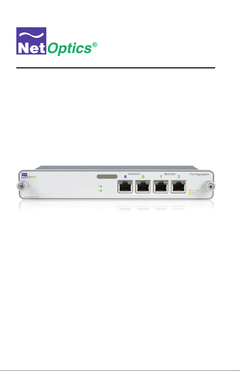
Product Diagrams
10/100 to Triple-speed Port Aggregator
®
www.netoptics.com
Figure 1: Front Panel
LED Indicators
• 1 / 2: Main and Redundant Power. If the Tap is deployed with both power
supplies, both LEDs will illuminate when the Tap is plugged in. If an LED
is off, this indicates that the corresponding power supply is not functioning.
• Link Speed Indicator: Located in the upper left corner of each RJ45 con-
nector. It illuminates solid amber for a 10Mbps link, yellow for a 100Mbps
link, and green for a 1000Mbps link.
• Link/Activity Indicator: Located in the upper right corner of each RJ45
connector. If a good link is established, the LED illuminates a steady green.
If there is current activity on this link, the LED ashes.
In- Lin e
2
1
Power LEDs
Network Monitor
A B
Network Ports
A & B
1
2
Monitor Ports
1 & 2
Port Aggregator
10
LINK
ACT
100
1000
5
Page 10

10/100 to Triple-speed Port Aggregator
Device 2
Application Diagrams: Memory Operation
All trafc that passes through the Tap is sent to the monitoring device NIC on
a rst-in, rst-out basis, including trafc that is temporarily stored in memory.
If two packets enter at the same time then one packet is processed while the
other is stored briey in memory, preventing collisions.
When there is a burst of data, trafc in excess of the NIC's capacity is sent to
the Tap's memory. Up to one gigabyte of data from the full-duplex stream can
be stored in memory. Memory continues to ll until its capacity is reached, or
the burst ends – whichever comes rst.
In both cases, the Tap applies a rst-in, rst out procedure, processing stored
data before new data from the link. If memory lls before the burst ends, the
memory stays lled as the stored data is processed – data that leaves the buffer
is immediately replaced. If the burst ends before the memory lls, memory
clears until the full gigabyte of capacity is available, or until another burst in
excess of the NIC's capacity requires additional memory.
The following three diagrams illustrate a simple example of a 100 Mbps NIC
moving from 80 percent utilization, to 140 percent utilization, then back to 80
percent utilization.
State 1: Side A + Side B is less than or equal
to 100% of the NIC's receive utilization
Example: On a 100 Mbps link, Side A is at 30 Mbs and Side B
is at 50 Mbps. The NIC receives 80 Mbps of traffic
(80% utilization), so no memory is required for the
monitoring device NIC to process all full-duplex traffic.
Side A
10/100 to
30 Mbps
Triple-speed
Port Aggregator
B 21A
Side B
50 Mbps
Side A + Side B
80 Mbps
Side A + Side B
80 Mbps
96443
Monitoring
Device 1
FirewallRouter
1
Using a single NIC each, both
monitoring devices receive all
combined traffic from Side A
and Side B, including physical
layer errors.
Figure 2: 80% Utilization
Monitoring
6
Page 11

State 2: Side A + Side B becomes greater than
Device 2
100% of the NIC's receive utilization
Example: There is a burst of traffic, so Side A is now at
90 Mbps while Side B remains at 50 Mbps. The NIC's
utilization is at 140%, requiring the use of memory
to help prevent data loss.
Memory
2
Traffic to the 100 Mbps
monitoring devices is limited
to 100 Mbps. The extra
40 Mbps of traffic is stored
in a 1 gigabyte buffer.
Memory continues to fill until
the 1 gigabyte capacity is
reached, or the burst ends.
Figure 3: 140% Utilization
State 3: Side A + Side B is once again less
than 100% of the NIC's receive utilization
10/100 to Triple-speed Port Aggregator
10/100 to
Side A
90 Mbps
Triple-speed
Port Aggregator
B 21A
Side B
50 Mbps
Side A +
Side B
limited to
100 Mbps
96443
Monitoring
Device 1
Monitoring
FirewallRouter
1
Using a single NIC each, both
monitoring devices receive all
combined traffic from Side A
and Side B, including physical
layer errors.
Example: On a 100 Mbps link, Side A is again at 30 Mbps and
Side B remains at 50 Mbps. The NIC's utilization is again at 80%.
10/100 to
Side A
30 Mbps
Triple-speed
Port Aggregator
96443
Side B
50 Mbps
Memory
1
The Tap applies a first-in, first-out
process to all packets. Once the
burst has ended and the NIC's
utilization is again below 100
percent, the Tap first processes
the packets that were stored in
memory. As long as the NICʼs
utilization remains below 100
percent, this process continues
uninterrupted until the memory clears.
Side A +
Side B
Monitoring
Device 1
Figure 4: Return to 80% Utilization
7
B 21A
Monitoring
Device 2
FirewallRouter
2
Once the memory has cleared, the
monitoring devices begins receiving
new data directly from the link. Using
a single NIC each, both monitoring
devices again receive all traffic from
Side A and Side B, including physical
layer errors.
Page 12

10/100 to Triple-speed Port Aggregator
Cabling Guidelines
Use straight-through cables to connect the Network ports to routers or NICs.
Use cross-over cables to connect the Network ports to switches and hubs. The
Network ports transmit on pins 3 & 6 and receive on pins 1 & 2.
Note: ________________________________________________________________
Network Ports A and B automatically detect and match the speed and duplex
settings of the attached network devices.
______________________________________________________________________
Connecting to the Network
1. Connect Network Port A to the appropriate network device following the
cabling guidelines above.
2. Connect Network Port B to the appropriate network device following the
cabling guidelines above.
3. Verify that the Tap Network Ports are cabled in-line between two devices.
®
www.netoptics.com
To network switch or router
In- Lin e
2
1
Figure 5: Connecting to the Network
Network Monitor
A B
8
2
Port Aggregator
10
100
1000
1
To network switch or router
LINK
ACT
Page 13

10/100 to Triple-speed Port Aggregator
Connecting to the Monitoring Devices
1. Supply power to the Tap using the two power supplies included with the
unit. The use of the second redundant power supply is optional.
Note: ________________________________________________________________
The second power supply is available to support the ow of trafc to the monitoring device, in the event that the rst power supply becomes unavailable. If
the rst power supply is unavailable, the second power supply will supply all
power for the Tap. Even if no power is available to the passive Tap, network
trafc ows uninterrupted.
______________________________________________________________________
2. Verify that the Power LEDs illuminate. PWR 1 illuminates when the rst
power supply is in use, and PWR 2 illuminates when the second power
supply is in use. Both power supplies can be plugged into the Tap at the
same time.
3. Connect Monitor Port 1 to the appropriate port on the monitoring
device using a CAT5 RJ45 straight-through cable to monitor the fullduplex link.
4. Connect Monitor Port 2 to the appropriate port on the monitoring device
using a CAT5 RJ45 straight-through cable to monitor the full-duplex link.
®
www.netoptics.com
In- Lin e
2
1
To monitoring device 1
Figure 6: Connecting to Monitoring Devices
9
Network Monitor
A B
To monitoring device 2
1
2
Port Aggregator
10
LINK
ACT
100
1000
Page 14

Specications
Environment
Operating Temperature: 0˚C to 40˚C
Storage Temperature: -10˚C to 70˚C
Relative Humidity: 10% min, 95% max, non-condensing
Power
Power Supply Input:
100-240VAC, 0.5A, 47-63Hz
Output: 12V, 5A
Mechanical
Dimensions: 1.125" high x 11.0" deep x 8.75" wide
Cable Interface
Copper Cable Type: 22-24 AWG unshielded twisted pair cable,
CAT5/CAT5e
Connectors
(2) RJ45, 8-pin connectors (network ports)
(2) RJ45, 8-pin connectors (monitor ports)
10/100 to Triple-speed Port Aggregator
Certications
Fully RoHS compliant
10
Page 15

10/100 to Triple-speed Port Aggregator
Limitations on Warranty and Liability
Net Optics offers a limited warranty for all its products. IN NO EVENT SHALL NET OPTICS, INC.
BE LIABLE FOR ANY DAMAGES INCURRED BY THE USE OF THE PRODUCTS (INCLUDING BOTH HARDWARE AND SOFTWARE) DESCRIBED IN THIS MANUAL, OR BY ANY
DEFECT OR INACCURACY IN THIS MANUAL ITSELF. THIS INCLUDES BUT IS NOT LIMITED TO LOST PROFITS, LOST SAVINGS, AND ANY INCIDENTAL OR CONSEQUENTIAL
DAMAGES ARISING FROM THE USE OR INABILITY TO USE THIS PRODUCT, even if Net
Optics has been advised of the possibility of such damages. Some states do not allow the exclusion
or limitation of implied warranties or liability for incidental or consequential damages, so the above
limitation or exclusion may not apply to you.
Net Optics, Inc. warrants this Tap to be in good working order for a period of ONE YEAR from the
date of purchase from Net Optics or an authorized Net Optics reseller.
Should the unit fail anytime during the said ONE YEAR period, Net Optics will, at its discretion,
repair or replace the product. This warranty is limited to defects in workmanship and materials and
does not cover damage from accident, disaster, misuse, abuse or unauthorized modications.
If you have a problem and require service, please call the number listed at the end of this section and
speak with our technical service personnel. They may provide you with an RMA number, which must
accompany any returned product. Return the product in its original shipping container (or equivalent)
insured and with proof of purchase.
Additional Information
Net Optics, Inc. reserves the right to make changes in specications and other information contained
in this document without prior notice. Every effort has been made to ensure that the information in
this document is accurate. Net Optics is not responsible for typographical errors.
THE WARRANTY AND REMEDIES SET FORTH ABOVE ARE EXCLUSIVE AND IN LIEU OF
ALL OTHERS, EXPRESS OR IMPLIED. No Net Optics reseller, agent, or employee is authorized
to make any modication, extension, or addition to this warranty.
Net Optics is always open to any comments or suggestions you may have about its products and/or
this manual.
Send correspondence to
Net Optics, Inc.
5303 Betsy Ross Drive
Santa Clara, CA 95054 USA
Telephone: +1 (408) 737-7777
Fax: +1 (408) 745-7719
Email: info@netoptics.com/Internet: www.netoptics.com
All Rights Reserved. Printed in the U.S.A. No part of this publication may be reproduced, transmitted, transcribed, stored in a retrieval system, or translated into any language or computer language,
in any form, by any means, without prior written consent of Net Optics, Inc., with the following
exceptions: Any person is authorized to store documentation on a single computer for personal use
only and that the documentation contains Net Optics' copyright notice.
11
Page 16

www.netoptics.com
© 2010 by Net Optics, Inc. All Rights Reserved.
 Loading...