

Page 1

Netopia™ R7200 SDSL Router
Nokia Speedlink™ certified
User’s Reference Guide
Page 2

Copyright
©2000, Netopia, Inc., v.0300
All rights reserved. Printed in the U.S.A.
This manual and any associated artwork, software, and product designs are copyrighted with
all rights reserved. Under the copyright laws such materials may not be copied, in whole or
part, without the prior written consent of Netopia, Inc. Under the law, copying includes
translation to another language or format.
Netopia, Inc.
2470 Mariner Square Loop
Alameda, CA 94501-1010
U.S.A.
Part Number
For additional copies of this electronic manual, order Netopia part number 6160021-PF-02
Printed Copies
For printed copies of this manual, order Netopia part number TER7200/Doc
(P/N 6160021-00-02)
Page 3

CCCCoooonnnntttteeeennnnttttss
ss
Welcome to the Netopia R7200 SDSL Router
your single source for information about your Netopia R7200 SDSL Router. It is intended to be
viewed on-line, using the powerful features of the Adobe Acrobat Reader. The information display
has been designed to present the maximum information in the minimum space on your screen. You
can keep this document open while you perform any of the procedures described and find useful
information about the procedure you are performing.
This Table of Contents page you are viewing consists of hypertext links to the chapters and
headings listed. If you are viewing this on-line, just click any link below to go to that heading.
User’s Reference Guide
. This guide is designed to be
Part I: Getting Started
Chapter 1 — Introduction..........................................................1-1
Overview....................................................................... 1-1
Features and capabilities ............................................... 1-1
How to use this guide .................................................... 1-2
Chapter 2 — Setting Up Internet Services .................................2-1
Finding an Internet service provider................................. 2-1
Unique requirements............................................ 2-2
Pricing and support.............................................. 2-2
Endorsements ..................................................... 2-2
Deciding on an ISP account............................................ 2-2
Setting up a Netopia R7200 account..................... 2-2
Obtaining an IP address........................................ 2-2
Obtaining information from the ISP.................................. 2-3
Local LAN IP address information to obtain............ 2-3
G
B
Chapter 3 — Making the Physical Connections..........................3-1
Find a location............................................................... 3-1
What you need .............................................................. 3-2
Identify the connectors and attach the cables.................. 3-2
Netopia R7200 SDSL Router back panel ports ................ 3-3
Netopia R7200 SDSL Router status lights....................... 3-4
Chapter 4 — Connecting to Your Local Area Network.................4-1
Overview....................................................................... 4-1
Readying computers on your local network....................... 4-1
Connecting to an Ethernet network.................................. 4-3
10Base-T............................................................. 4-4
Page 4

iv User’s Reference Guide
Adding an external modem ............................................. 4-5
Connecting to a LocalTalk network ................................. 4-6
Chapter 5 — Setting up your Router with the SmartStart Wizard 5-1
Before running SmartStart ............................................. 5-2
Setting up your Router with the SmartStart Wizard........... 5-3
SmartStart Wizard configuration screens ............... 5-3
Easy option.......................................................... 5-4
Advanced option .................................................. 5-5
Sharing the Connection.................................................. 5-6
Configuring TCP/IP on Windows 95, 98, or NT
computers........................................................... 5-6
Configuring TCP/IP on Macintosh computers........ 5-10
Chapter 6 — Console-Based Management.................................6-1
Connecting through a Telnet session............................... 6-2
Configuring Telnet software ................................... 6-3
Connecting a console cable to your router ....................... 6-3
Navigating through the console screens .......................... 6-4
Chapter 7 — Easy Setup...........................................................7-1
Easy Setup console screens........................................... 7-1
Accessing the Easy Setup console screens............ 7-1
Quick Easy Setup connection path .................................. 7-3
SDSL Line Configuration ....................................... 7-4
Easy Setup Profile................................................ 7-5
IP Easy Setup ...................................................... 7-6
Easy Setup Security Configuration ......................... 7-7
Part II: Advanced Configuration
Chapter 8 — WAN and System Configuration .............................8-1
WAN configuration.......................................................... 8-1
Creating a new Connection Profile................................... 8-3
The default profile.......................................................... 8-6
Page 5

Contents v
IP parameters (default profile) screen .................... 8-8
IPX parameters (default profile) screen .................. 8-9
System configuration screens ........................................ 8-9
Navigating through the system configuration screens...... 8-10
System configuration features............................. 8-11
Network protocols setup..................................... 8-12
Filter sets (firewalls)........................................... 8-12
IP address serving ............................................. 8-12
Date and time.................................................... 8-12
Console configuration......................................... 8-13
SNMP (Simple Network Management Protocol)..... 8-14
Security............................................................. 8-14
Upgrade feature set ........................................... 8-14
Logging ............................................................. 8-14
Installing the Syslog client .................................. 8-15
Chapter 9 — Line Backup .........................................................9-1
WAN Configuration......................................................... 9-2
Backup Configuration screen................................. 9-3
IP Setup screen............................................................. 9-4
Connection Profiles........................................................ 9-5
Using Scheduled Connections with Backup...................... 9-5
Management/Statistics.................................................. 9-7
QuickView ..................................................................... 9-9
Event Logs.................................................................... 9-9
SNMP Support .............................................................. 9-9
G
Chapter 10 — IP Setup and Network Address Translation ........10-1
Network Address Translation features ........................... 10-1
Using Network Address Translation............................... 10-3
Associating port numbers with nodes.................. 10-6
Advanced IP/IPX router configuration options................. 10-7
Connection Profiles...................................................... 10-8
Network Address Translation guidelines............. 10-10
Page 6

vi User’s Reference Guide
IP setup.................................................................... 10-11
IP subnets....................................................... 10-15
Static routes.................................................... 10-17
IP address serving..................................................... 10-21
IP Address Pools.............................................. 10-24
DHCP NetBIOS Options..................................... 10-26
MacIP (KIP forwarding) setup ............................ 10-28
Chapter 11 — IPX Setup.........................................................11-1
IPX features ................................................................ 11-1
IPX definitions ............................................................. 11-1
Internetwork Packet Exchange (IPX) ..................... 11-1
IPX address....................................................... 11-2
Socket .............................................................. 11-2
Routing Information Protocol (RIP) ....................... 11-2
Service Advertising Protocol (SAP)....................... 11-2
NetBIOS............................................................ 11-3
IPX spoofing....................................................... 11-3
IPX setup screen ......................................................... 11-3
IPX routing tables ........................................................ 11-5
Chapter 12 — AppleTalk Setup................................................12-1
AppleTalk networks ...................................................... 12-1
AppleTalk protocol.............................................. 12-1
MacIP................................................................ 12-3
AURP................................................................. 12-3
Routers and seeding .......................................... 12-3
Installing AppleTalk ...................................................... 12-4
Configuring AppleTalk ................................................... 12-6
EtherTalk setup.................................................. 12-6
LocalTalk setup ................................................. 12-7
AURP setup ....................................................... 12-8
Page 7

Contents vii
Chapter 13 — Monitoring Tools...............................................13-1
Quick View status overview .......................................... 13-1
General status................................................... 13-2
Current status ................................................... 13-3
Status lights...................................................... 13-3
Statistics & Logs......................................................... 13-4
General Statistics .............................................. 13-4
Event histories ............................................................ 13-5
Routing tables............................................................. 13-7
Served IP Addresses.................................................. 13-10
System Information.................................................... 13-12
SNMP....................................................................... 13-12
The SNMP Setup screen................................... 13-13
SNMP traps..................................................... 13-14
Web-based management pages .................................. 13-16
System Information page.................................. 13-16
Event History pages ......................................... 13-17
G
Chapter 14 — Security ...........................................................14-1
Suggested security measures....................................... 14-1
User accounts............................................................. 14-1
Dial-in console access.................................................. 14-3
Enable SmartStart/SmartView/Web server ................... 14-4
Telnet access .............................................................. 14-4
About filters and filter sets ........................................... 14-4
What’s a filter and what’s a filter set?.................. 14-4
How filter sets work............................................ 14-5
How individual filters work................................... 14-6
Design guidelines............................................. 14-11
Working with IP filters and filter sets............................ 14-12
Adding a filter set............................................. 14-13
Viewing filter sets............................................. 14-16
Modifying filter sets.......................................... 14-17
Page 8

viii User’s Reference Guide
Deleting a filter set........................................... 14-17
A sample IP filter set........................................ 14-17
IPX filters .................................................................. 14-21
IPX packet filters.............................................. 14-22
IPX packet filter sets ........................................ 14-23
IPX SAP filters.................................................. 14-25
IPX SAP filter sets ............................................ 14-27
Firewall tutorial.......................................................... 14-29
General firewall terms ...................................... 14-29
Basic IP packet components............................. 14-29
Basic protocol types......................................... 14-29
Firewall design rules......................................... 14-30
Filter basics..................................................... 14-33
Example filters................................................. 14-34
Chapter 15 — Utilities and Diagnostics...................................15-1
Ping............................................................................ 15-2
Trace Route................................................................. 15-4
Telnet client................................................................. 15-5
Disconnect Telnet console session ............................... 15-6
Factory defaults........................................................... 15-6
Transferring configuration and firmware files with TFTP.... 15-7
Updating firmware .............................................. 15-7
Downloading configuration files ........................... 15-8
Uploading configuration files ............................... 15-9
Transferring configuration and firmware files with
XMODEM..................................................................... 15-9
Updating firmware ............................................ 15-10
Downloading configuration files ......................... 15-11
Uploading configuration files ............................. 15-11
Restarting the system................................................ 15-12
Page 9

Contents ix
Part III: Appendixes
Appendix A — Troubleshooting..................................................A-1
Configuration problems .................................................. A-1
Console connection problems ............................... A-2
Network problems................................................ A-2
How to reset the router to factory defaults ...................... A-3
Power outages............................................................... A-3
Technical support .......................................................... A-4
How to reach us................................................... A-4
Appendix B — Understanding IP Addressing ..............................B-1
What is IP?.................................................................... B-1
About IP addressing....................................................... B-1
Subnets and subnet masks .................................. B-2
Example: Using subnets on a Class C IP internet.... B-3
Example: Working with a Class C subnet................ B-5
Distributing IP addresses ............................................... B-5
Technical note on subnet masking......................... B-6
Configuration ....................................................... B-7
Manually distributing IP addresses ........................ B-8
Using address serving.......................................... B-8
Tips and rules for distributing IP addresses............ B-9
Nested IP subnets....................................................... B-11
Broadcasts.................................................................. B-13
Packet header types........................................... B-13
G
Appendix C — Understanding Netopia NAT Behavior...................C-1
Network configuration..................................................... C-1
Background................................................................... C-1
Exported services................................................ C-5
Important notes................................................... C-6
Configuration................................................................. C-7
Summary...................................................................... C-8
Page 10

x User’s Reference Guide
Appendix D — Binary Conversion Table......................................D-1
Appendix E — Further Reading..................................................E-1
Appendix F — Technical Specifications and Safety Information...F-1
Pinouts for Auxiliary port modem cable............................ F-1
Description.................................................................... F-2
Power requirements ............................................. F-2
Environment ........................................................ F-2
Software and protocols......................................... F-3
Agency approvals........................................................... F-4
Regulatory notices ............................................... F-4
Important safety instructions ................................ F-5
Appendix G — About SDSL........................................................G-1
Glossary..................................................................................GL-1
Index ..................................................................................Index-1
Limited Warranty and Limitation of Remedies................................1
Page 11

PPPPaaaarrrrtttt IIII:::: GGGGeeeettttttttiiiinnnngggg SSSSttttaaaarrrrtttteeeedd
dd
Page 12

User’s Reference Guide
Page 13

Introduction 1-1
CCCChhhhaaaapppptttteeeerrrr 11
IIIInnnnttttrrrroooodddduuuuccccttttiiiioooonn
11
nn
Overview
The Netopia R7200 SDSL Router is a full-featured, stand-alone, multiprotocol router for connecting diverse local
area networks (LANs) to the Internet and other remote networks. Once your Netopia R7200 SDSL Router is
connected to your computer, and your account is activated by your network service provider, you will have a fast
Symmetric Digital Subscriber Line (SDSL) connection between your PC or LAN and the telephone company’s
network of high-speed digital facilities.
This section covers the following topics:
■
“Features and capabilities” on page 1-1
■
“How to use this guide” on page 1-2
Features and capabilities
The Netopia R7200 SDSL Router provides the following features:
■
Certified for use with the Speedlink™ access concentrator from Nokia
Support for IP and IPX routing for Internet and intranet connectivity
■
IP address serving (over Ethernet or a WAN link) that allows local or remote network nodes to acquire an IP
■
address automatically and dynamically from a designated pool of available addresses
■
Multi-speed symmetrical transmission from 192 Kbps up to 1.5 Mbps to provide scalability without
additional equipment investment
All digital, continuous-availability networking, eliminating dialing and providing lower, more predictable
■
transmission costs
■
Connectivity to Ethernet LANs via a built-in 8-port 10Base-T hub with uplink port
■
Status lights (LEDs) for easy monitoring and troubleshooting
Support for console-based management over Telnet or serial cable connection
■
■
Support for remote configuration by your reseller, your network administrator, or technicians at Netopia,
Inc., via external modem or via IP network
■
Wall-mountable, bookshelf (side-stackable), or desktop-stackable design for efficient space usage
SmartIP™, making it simple and economical to connect a workgroup of users to the Internet or a remote IP
■
network by using Network Address Translation and a single IP address
■
AppleTalk support (available as a separate add-on AppleTalk kit, including a firmware feature set
enhancement and custom HD-15 dual RJ-11 PhoneNET® connector), allowing for LocalTalk-to-Ethernet
routing, assigning IP addresses to Macintosh users (MacIP), IP functionality for LocalTalk users, and AURP
Page 14

1-2 User’s Reference Guide
tunneling for connectivity between remote AppleTalk networks
Web-based management pages aid in managing your router. Internet browsers such as Netscape Navigator
■
and Microsoft’s Internet Explorer can be used for the web-based management pages.
How to use this guide
This guide is designed to be your single source for information about your Netopia R7200 SDSL Router. It is
intended to be viewed on-line, using the powerful features of the Adobe Acrobat Reader. The information display
has been deliberately designed to present the maximum information in the minimum space on your screen. You
can keep this document open while you perform any of the procedures described and find useful information
about the procedure you are performing.
If you prefer to work from hard copy rather than on-line documentation, you can also print out all of the manual,
or individual sections. The pages are formatted to print on standard 8 1/2 by 11 inch paper. We recommend
that you print on three-hole punched paper, so you can put the pages in a binder for future reference. For your
convenience, a printed copy can be purchased from Netopia. Order part number TER7200/Doc.
This guide is organized into chapters describing the Netopia R7200’s advanced features. You may want to read
each chapter’s introductory section to familiarize yourself with the various features available.
Use the guide’s table of contents and index to locate informational topics.
Page 15

Setting Up Internet Services 2-1
CCCChhhhaaaapppptttteeeerrrr 22
SSSSeeeettttttttiiiinnnngggg UUUUpppp IIIInnnntttteeeerrrrnnnneeeetttt SSSSeeeerrrrvvvviiiicccceeeess
This chapter describes how to obtain and set up Internet services.
This section covers the following topics:
■
“Finding an Internet service provider” on page 2-1
“Deciding on an ISP account” on page 2-2
■
“Obtaining information from the ISP” on page 2-3
■
Note:
Some companies act as their own ISP. For example, some organizations have branch offices that can
use the Netopia R7200 to access the Internet via the main office in a point-to-point scenario. If you install the
Netopia R7200 in this type of environment, refer to the following sections for specific information you must
receive from the network administrator to configure the Netopia R7200 properly.
22
ss
Finding an Internet service provider
The Netopia R7200 SDSL Router provides its high speed symmetric (two-way) digital connection to the Internet
through a Competitive Local Exchange Carrier (CLEC) -- a type of mini phone company. The CLEC uses a
compatible type of switching equipment known as a Digital Subscriber Line Access Multiplexer (DSLAM). The
DSLAM that you connect to with your Netopia Router must be capable of handling these symmetric connections.
The Netopia R7200 is certified for use with the Nokia Speedlink™ DSLAM.
If you have purchased your Netopia Router through a Netopia ISP partner, you can be sure that an account that
supports SDSL connections will be available.
If your area has more than one ISP , the following considerations will help you decide which ISP is best suited for
your requirements.
In determining which Internet service provider (ISP) to establish your account with, make sure that your ISP
supports connections via a CLEC with a compatible DSLAM, the Nokia’s Speedlink™ central office equipment.
Use an ISP that provides Internet access through a Symmetric Digital Subscriber Line (SDSL) and that supports
the Netopia R7200 SDSL Router. If you would like to use an ISP that you already have a relationship with but
that is not familiar with the Netopia R7200, call us at 1-800-NETOPIA. Our representative can call your ISP and
introduce them to the product. If necessary, we will provide them with the technical background they need to
support the product.
Page 16

2-2 User’s Reference Guide
Unique requirements
Make sure the ISP can meet any unique requirements you may have, such as:
■
Dynamic or static IP addressing
Class C IP address
■
■
Custom domain name
■
Multiple e-mail addresses
Web site hosting
■
Pricing and support
Compare pricing, service, and technical support service among various ISPs.
Endorsements
Consider recommendations from colleagues and reviews in publications. Netopia lists Netopia Certified ISPs on
our Web site at
http://www.netopia.com
.
Deciding on an ISP account
Your ISP may offer various Internet access account plans. Typically, these plans vary by usage charges and the
number of host IP addresses supplied. Evaluate your networking needs and discuss them with your ISP before
deciding on a plan for your network.
Setting up a Netopia R7200 account
Check whether your ISP has the Netopia R7200 on its list of supported products that have been tested with a
particular configuration. If the ISP does not have the Netopia R7200 on such a list, describe the Netopia R7200
in as much detail as needed, so your ISP account can be optimized. As appropriate, refer your ISP to Netopia’s
Web site www.netopia.com for more information.
Obtaining an IP address
Typically, each network computer that requires Internet access requires its own unique IP address. If some or
all network computers require simultaneous Internet access, obtain a block of IP host addresses large enough
for each computer to have its own address, plus one for the Netopia R7200.
Consider expected growth in your network when deciding on the number of addresses to obtain. Alternatively,
you can use the Network Address Translation feature of SmartIP.
SmartIP
The Netopia R7200 SDSL Router supports the SmartIP™ feature, which includes Network Address Translation.
Network Address Translation provides Internet access to the network connected to the Netopia R7200 using
only a single IP address. These routers translate between the internal or local area network (LAN) addresses
and a single external IP address, and route accordingly.
Page 17

Setting Up Internet Services 2-3
For more information on Network Address Translation, see Chapter 10, “IP Setup and Network Address
Translation.”
Obtaining information from the ISP
After your account is set up, the ISP should send you the IP parameter information that will help you configure
the Netopia R7200.
Local LAN IP address information to obtain
Your ISP will need to provide you with the following information:
The default gateway IP address (same as remote IP address in most cases)
■
■
Local WAN IP address and subnet mask
■
Primary and secondary domain name server (DNS) IP addresses
Domain name (usually the same as the ISP’s domain name unless you have registered for your own
■
individual domain name)
Note:
The default gateway, WAN address and mask, DNS, and domain name are all obtainable via WAN DHCP,
if your ISP supports it.
With Network Address Translation
If you are using SmartIP (NAT), you should obtain the following:
If you are connecting to a remote site using Network Address Translation on your router, your provider will
■
not define the IP address information on your local LAN. You can define this information based on an IP
configuration that may already be in place for the existing network. Alternatively, you can use the default IP
address range used by the router.
Without Network Address Translation
If you are not using Network Address Translation, you will need to obtain all of the local LAN IP address
information from your ISP.
If you are not using SmartIP (NAT), you should obtain:
■
The number of Ethernet IP host addresses available with your account and the first usable IP host address
in the address block
The Ethernet IP address for your Netopia R7200
■
The Ethernet IP subnet mask address for your Netopia R7200
■
Page 18

2-4 User’s Reference Guide
Page 19

Making the Physical Connections 3-1
CCCChhhhaaaapppptttteeeerrrr 33
MMMMaaaakkkkiiiinnnngggg tttthhhheeee PPPPhhhhyyyyssssiiiiccccaaaallll CCCCoooonnnnnnnneeeeccccttttiiiioooonnnnss
This section tells you how to make the physical connections to your Netopia R7200 SDSL Router. This section
covers the following topics:
■
“Find a location” on page 3-1
■
“What you need” on page 3-2
“Identify the connectors and attach the cables” on page 3-2
■
■
“Netopia R7200 SDSL Router back panel ports” on page 3-3
■
“Netopia R7200 SDSL Router status lights” on page 3-4
33
ss
Find a location
When choosing a location for the Netopia Router, consider:
Available space and ease of installation
■
Physical layout of the building and how to best use the physical space available for connecting your Netopia
■
Router to the LAN
■
Available wiring and jacks
Distance from the point of installation to the next device (length of cable or wall wiring)
■
■ Ease of access to the front of the unit for configuration and monitoring
■ Ease of access to the back of the unit for checking and changing cables
■ Cable length and network size limitations when expanding networks
For small networks, install the Netopia R7200 near one of the LANs. For large networks, you can install the
Netopia R7200 in a wiring closet or a central network administration site.
Page 20

3-2 User’s Reference Guide
What you need
Locate all items that you need for the installation.
Included in your router package are:
■ The Netopia R7200 SDSL Router
■ A power adapter and cord with a mini-DIN8 connector
■ One RJ-45 Ethernet cable
■ One RJ-11 Telco (or Line) cable
■ A dual DE-9 and mini-DIN8 to DE-9 console cable (for a PC or a Macintosh)
■ The Netopia CD containing an Internet browser, Adobe Acrobat Reader for Windows and Macintosh, ZT erm
terminal emulator software and NCSA Telnet for Macintosh, and documentation
You will need:
■ A Windows 95 or 98–based PC or a Macintosh computer with Ethernet connectivity for configuring the
Netopia R7200. This may be built-in Ethernet or an add-on card, with TCP/IP installed and configured. See
“Before running SmartStart” on page 5-2.
■ An SDSL wall outlet wired for a connection to a Competitive Local Exchange Carrier (CLEC) who supports
Symmetric Digital Subscriber Line connections.
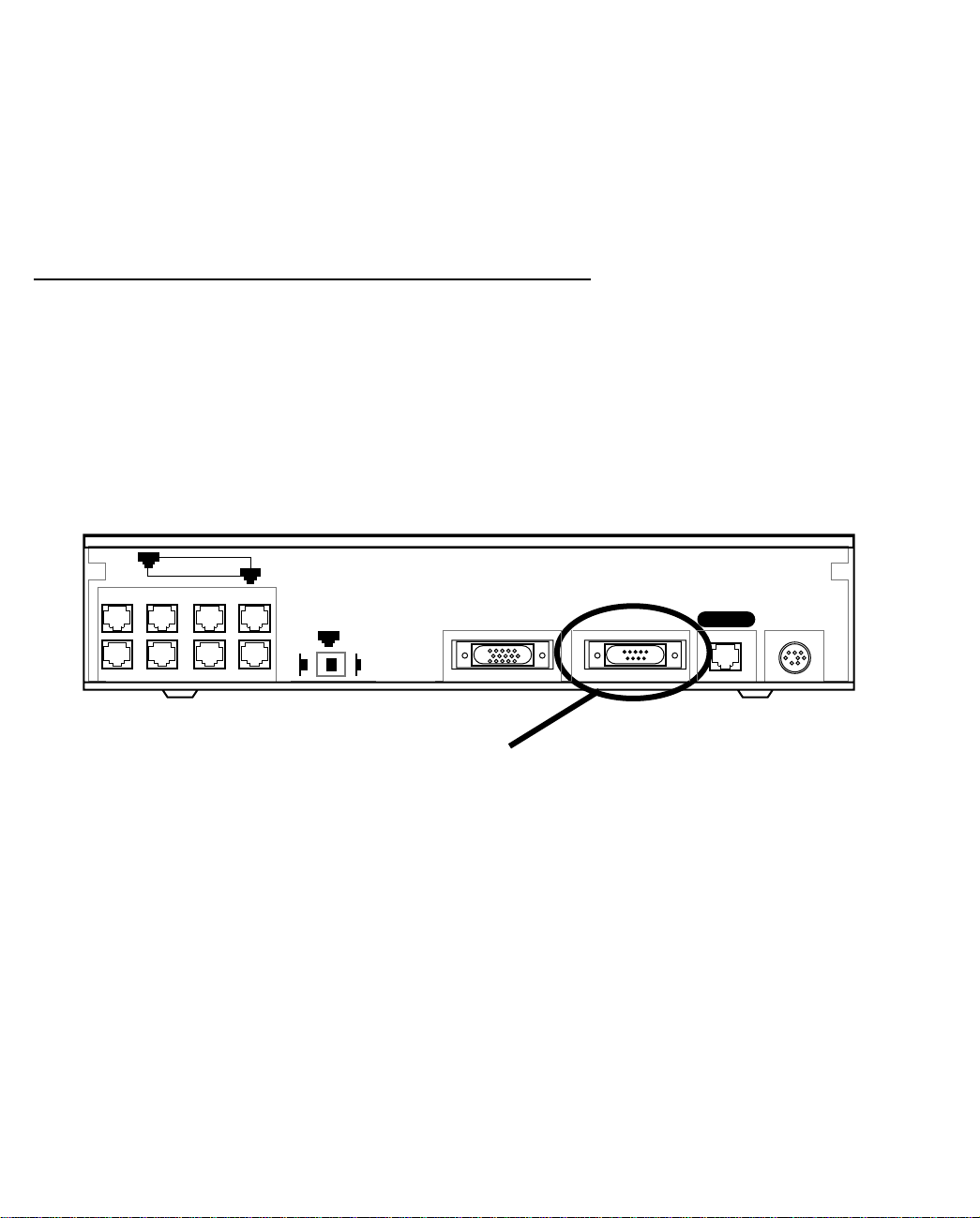
Identify the connectors and attach the cables
Identify the connectors and switches on the back panel and attach the necessary Netopia Router cables.
The figure below displays the back of the Netopia R7200 SDSL Router.
Netopia R7200 with SDSL back panel
Line port
8
Ethernet
8 port Ethernet hub
1. Connect the mini-DIN8 connector from the power adapter to the power port, and plug the other end into an
electrical outlet.
2. Connect one end of the RJ-11 cable to the Line port, and the other end to your SDSL wall outlet.
1
Normal
1
Uplink
Crossover switch
Auxiliary Console Power
Line
Auxiliary port
Console port
Power port
Page 21

Making the Physical Connections 3-3
3. Connect the Ethernet cable to any of the Ethernet ports on the router.
(If you are connecting the router to an existing Ethernet hub, use Ethernet port #1 on the router and set the
crossover switch to the Uplink position.)
You should now have: the power adapter plugged in; the Ethernet cable connected between the router and
your computer; and the SDSL cable connected between the router and the SDSL wall outlet.
Netopia R7200 SDSL Router back panel ports
The following table describes all the Netopia R7200 SDSL Router back panel ports.
Port Description
Power port A mini-DIN8 power adapter cable connection.
Line port An RJ-11 telephone-style jack labeled Line for your SDSL connection.
Console port A DE-9 console port for a direct serial connection to the console screens. You
can use this if you are an experienced user. See “Connecting a console cable to
your router” on page 6-3.
Auxiliary port An HD-15 auxiliary port for attaching an external modem or the optional
AppleTalk kit.
Crossover switch A crossover switch with Normal and Uplink positions. If you use Ethernet Port
#1 for a direct Ethernet connection between a computer and the router, set the
switch to the Normal position. If you are connecting the router to an Ethernet
hub, use Ethernet port #1 on the router and set the switch to the Uplink
position.
8-port Ethernet hub Eight Ethernet jacks. Y ou will use one of these to configure the Netopia R7200.
For a new installation, use the Ethernet connection. Alternatively, you can use
the console connection to run console-based management using a direct serial
connection. Y ou can either connect your computer directly to any of the Ethernet
ports on the router, or connect both your computer and the router to an existing
Ethernet hub on your LAN.
Page 22

3-4 User’s Reference Guide
Netopia R7200 SDSL Router status lights
The figure below represents the Netopia R7200 status light (LED) panel.
Netopia R7200 LED front panel
2 3 4 5 6 7 8 9 10 11 12 13 14 15 16171819 20 21
1
Link/Receive
Power
Management
Ready
Channel 1
WAN 1 WAN 2 Ethernet
Console
Channel 2
Auxiliary
Management
Ready
Channel 1
Channel 2
Traffic
Collision
The following table summarizes the meaning of the various LED states and colors:
When this happens... the LEDs...
The WAN interface is operational 3 is green.
The line is unavailable 3 flashes red.
The WAN has carrier 4 is green.
Data is transmitted or received on the WAN 4 flashes yellow.
Carrier is asserted 6 and 7 are green.
Data is transmitted or received 6 and 7 flash yellow.
Data is transmitted or received by the ethernet controller 12 flashes yellow.
The Ethernet interface detects a collision 13 flashes red.
Link is detected 14 though 21 are solid green.
Data are received on their respective ports 14 though 21 flash green.
Note: 5 and 8 through 11 are unused, since the SDSL link is carried only on WAN channel 1. Also, Console
carrier (6) is ignored if the console is not configured for a remote modem.
Page 23

Connecting to Your Local Area Network 4-1
CCCChhhhaaaapppptttteeeerrrr 44
CCCCoooonnnnnnnneeeeccccttttiiiinnnngggg ttttoooo YYYYoooouuuurrrr LLLLooooccccaaaallll AAAArrrreeeeaaaa NNNNeeeettttwwwwoooorrrrkk
This chapter describes how to physically connect the Netopia R7200 to your local area network (LAN). Before
you proceed, make sure the Netopia R7200 is properly configured. You can customize the router’s configuration
for your particular LAN requirements using console-based management (see “Console-Based Management” on
page 6-1).
This section covers the following topics:
■ “Overview” on page 4-1
■ “Readying computers on your local network” on page 4-1
■ “Connecting to an Ethernet network” on page 4-3
■ “Adding an external modem” on page 4-5
■ “Connecting to a LocalTalk network” on page 4-6
44
kk
Overview
You can connect the Netopia R7200 to an IP or IPX network that uses Ethernet.
If you have purchased the AppleTalk feature expansion kit, you can also connect the router to a LocalTalk
network that uses PhoneNET cabling.
Additionally, you can connect an external modem. See “Adding an external modem” on page 4-5.
Caution!
Before connecting the Netopia R7200 to any AppleTalk LANs that contain other AppleTalk routers, you should
read “Routers and seeding” on page 12-3.
See the later sections in this chapter for details on how to connect the Netopia R7200 to different types of
networks.
Readying computers on your local network
PC and Macintosh computers must have certain components installed before they can communicate through
the Netopia R7200. The following illustration shows the minimal requirements for a typical PC or Macintosh
computer.
Page 24

4-2 User’s Reference Guide
Application software
TCP/IP stack
Ethernet/EtherTalk/LocalTalk Driver
Your PC
or Macintosh
computer
To the Netopia R7200
Application software: This is the software you use to send e-mail, browse the World Wide Web, read
newsgroups, etc. These applications may require some configuration. Examples include the Eudora e-mail client
and the Web browsers Microsoft Internet Explorer and Netscape Navigator.
TCP/IP stack: This is the software that lets your PC or Macintosh computer communicate using Internet
protocols. TCP/IP stacks must be configured with some of the same information you used to configure the
Netopia R7200. There are a number of TCP/IP stacks available for PC computers. Windows 95 includes a
built-in TCP/IP stack. See “Configuring TCP/IP on Windows 95, 98, or NT computers” on page 5-6. Macintosh
computers use either MacTCP or Open Transport. See “Configuring TCP/IP on Macintosh computers” on
page 5-10.
Ethernet: Ethernet hardware and software drivers enable your PC or Macintosh computer to communicate on
the LAN.
EtherTalk and LocalTalk: These are AppleTalk protocols used over Ethernet.
Once the Netopia R7200 is properly configured and connected to your LAN, PC and Macintosh computers that
have their required components in place will be able to connect to the Internet or other remote IP networks.
Page 25

Connecting to Your Local Area Network 4-3
Connecting to an Ethernet network
The Netopia R7200 supports Ethernet connections through its eight Ethernet ports. The router automatically
detects which Ethernet port is in use.
You can connect either 10Base-T or EtherWave Ethernet networks to the Netopia R7200.
The following table displays some important attributes of these types of Ethernet.
Attribute EtherWave 10Base-T
Max. length of backbone,
branch, or end to end (cable
length)
Cable type
Netopia R7200 port used Ethernet Ethernet
Other restrictions
330 feet
(100 meters)
Twisted pair
(10Base-T)
Maximum 8
devices (daisy
chained)
330 feet
(100 meters)
Twisted pair
(10Base-T)
No daisy
chain
Page 26

4-4 User’s Reference Guide
10Base-T
You can connect a standard 10Base-T Ethernet network to the Netopia R7200 using any of its available
Ethernet ports.
Netopia R7200 back panel
8
Ethernet
1
Normal
1
Uplink
The Netopia R7200 in a 10Base-T network
T o connect your 10Base-T network to the Netopia
R7200 through an Ethernet port, use a 10Base-T
cable with RJ-45 connectors.
If you have more than eight devices to connect,
you can attach additional devices using another
10Base-T hub.
Auxiliary Console Power
8
Ethernet
Line
1
Nor-
Page 27

If you add devices connected
through a hub, connect the hub to
Ethernet port number 1 on the
Netopia R7200 SDSL Router and
set the Normal/Uplink crossover
switch to Uplink.
PC
Adding an external modem
Macintosh
8
Connecting to Your Local Area Network 4-5
Ethernet
PC
1
Nor-
10Base-T
Hub
You may want to add an external modem to your Auxiliary port. Obtain the special DB-25 external modem cable
(TE6/DB25) either from your reseller or directly from Netopia.
Netopia R7200 Auxiliary port for connecting an external modem
8
Ethernet
1
Normal
1
Auxiliary Console Power
Uplink
Line
Auxiliary connection port
HD-15 (female)
By default, the Auxiliary port on your Netopia R7200 is enabled for remote console configuration via an external
asynchronous modem. This means that all you have to do is connect your modem to the Auxiliary port and
configure its settings in the Line Configuration screens under the WAN Configuration menu.
For pinout information on the HD-15 to DB-25 modem cable, see “Pinouts for Auxiliary port modem cable,” in
Appendix F, “Technical Specifications and Safety Information.”
Page 28

4-6 User’s Reference Guide
Connecting to a LocalTalk network
If you have purchased the AppleTalk feature expansion kit, you can also connect the router to an AppleTalk
network that uses either Ethernet or LocalTalk. Refer to the sheet of optional feature set add-ons in your
Netopia R7200 documentation folio.
The AppleTalk feature expansion kit includes a dual RJ-11 PhoneNET connector that attaches to the Auxiliary
port on the Netopia R7200.
Netopia R7200 Auxiliary port for connecting to LocalTalk
8
Ethernet
1
Normal
1
Auxiliary Console Power
Uplink
Line
Auxiliary connection port
HD-15 (female)
Connect the male HD-15 end of the LocalTalk cable to the Auxiliary port on your Netopia R7200. Connect the
other end of the cable to your LocalTalk network. You can use only one connection on the Auxiliary port. You
cannot use both the PhoneNET connector and an external modem.
If your LocalTalk network is not based on standard PhoneNET cabling, use a PhoneNET-to-LocalTalk adaptor
cable available from Farallon division of Netopia. Connect the adaptor cable’s RJ-11 connector to the AppleT alk
cable’s PhoneNET connector. Connect the cable’s mini-DIN-3 connector to your LocalTalk network.
Be sure to observe the standard rules governing maximum cable lengths and limits on the number of nodes on
a PhoneNET network. The dual RJ-11 PhoneNET connector allows insertion in the LocalT alk daisy chain or at the
end. If the device is connected at the end of the daisy chain, you must install the accompanying terminator.
For detailed configuration instructions see “AppleTalk Setup” on page 12-1.
Page 29

Setting up your Router with the SmartStart Wizard 5-1
CCCChhhhaaaapppptttteeeerrrr 55
SSSSeeeettttttttiiiinnnngggg uuuupppp yyyyoooouuuurrrr RRRRoooouuuutttteeeerrrr wwwwiiiitttthhhh tttthhhheeee SSSSmmmmaaaarrrrttttSSSSttttaaaarrrrtttt WWWWiiiizzzzaaaarrrrdd
Once you’ve connected your router to your computer and your telecommunications line and installed a web
browser, you’re ready to run the Netopia SmartStart™ Wizard. The SmartStart Wizard will help you set up the
router and share the connection. The SmartStart Wizard walks you through a series of questions and, based on
your responses, automatically configures the router for connecting your LAN to the Internet or to your remote
corporate network.
The SmartStart Wizard will:
■ automatically check your Windows 95, 98, or NT PC’s TCP/IP configuration to be sure you can accept a
dynamically assigned IP address, and change it for you if it is not set for dynamic addressing
■ check the physical connection from your computer to your router without your having to enter an IP address
■ assign an IP address to your router
This chapter covers the following topics:
■ “Before running SmartStart” on page 2
■ “Setting up your Router with the SmartStart Wizard” on page 3
■ “Sharing the Connection” on page 6
55
dd
Page 30

5-2 User’s Reference Guide
Before running SmartStart
Be sure you have connected the cables and power source as described in Step 1 “Connect the Router” guide
contained in your Netopia folio.
Before you launch the SmartStart application, make sure your computer meets the following requirements:
PC Macintosh
System
software
Connectivity
software
Connectivity
hardware
Browser
software
Notes:
• The computer running SmartStart must be on the same Ethernet cable segment as the Netopia R7200.
Repeaters, such as 10Base-T hubs between your computer and the Netopia R7200, are acceptable, but
devices such as switches or other routers are not.
• SmartStart for the PC will set your TCP/IP control panel to “Obtain an IP address automatically” if it is
not already set this way. This will cause your computer to reboot. If you have a specified IP address
configured in the computer, you should make a note of it before running SmartStart, in case you do not
want to use the dynamic addressing features built in to the Netopia Router and need to restore the fixed IP
address.
Windows 95, 98, or NT operating system MacOS 7.5 or later
TCP/IP must be installed and properly
configured. See “Configuring TCP/IP on
Windows 95, 98, or NT computers” on
page 5-6
Ethernet card (10Base-T) Either a built-in or third-party Ethernet card
Netscape Communicator™ or Microsoft Internet Explorer, included on the Netopia CD.
Required for web-based registration and web-based monitoring.
MacTCP or Open Transport TCP/IP must be
installed and properly configured. See
“Configuring TCP/IP on Macintosh
computers” on page 5-10.
(10Base-T)
Page 31

Setting up your Router with the SmartStart Wizard 5-3
Setting up your Router with the SmartStart Wizard
The SmartStart Wizard is tailored for your platform, but it works the same way on either a PC or a Macintosh.
Insert the Netopia CD, and in the desktop navigation screen that appears, launch the SmartStart Wizard
application.
SmartStart Wizard configuration screens
The screens described in this section are the default screens shipped on the Netopia CD. They
derive from two initialization (.ini) files included in the same directory as the SmartStart
application file. Your reseller or your ISP may have supplied you with customized versions of these
files.
■ If you have received a CD or diskette that has been customized by your reseller or ISP, you
can run the SmartStart Wizard directly from the CD or diskette and follow the instructions
your reseller or ISP provides. This makes your Netopia R7200 configuration even easier.
■ If you have received only the .ini files from your reseller or ISP, perform the following:
■ Copy the entire directory folder containing the SmartStart Wizard application from the
Netopia CD to your hard disk.
■ Copy the customized .ini files to the same directory folder that contains the SmartStart
Wizard application, allowing the copy process to overwrite the original .ini files.
■ Run the SmartStart Wizard from your hard disk. You can then follow the instructions your
reseller or ISP provides.
The SmartStart Wizard presents a series of screens to guide you through the preliminary configuration of a
Netopia R7200. It will then create a connection profile using the information you supply to it.
Welcome screen. The first screen welcomes you to the
SmartStart Wizard configuration utility.
Click the Next button after you have responded to the
interactive prompts in each screen.
The Help button will display useful information to assist
you in responding to the interactive prompts.
Page 32

5-4 User’s Reference Guide
Setup Options screen. You can choose either Easy or
Advanced setup.
■ If you choose Easy, SmartStart automatically uses
the preconfigured IP addressing setup built into your
router. This is the best choice if you are creating a
new network or don’t already have an IP addressing
scheme on your new network.
If you choose Easy, you will see a “Connection Test
screen,” like the one shown below while SmartStart
checks the connection to your router.
■ If you choose Advanced, skip to page 5-5 now. The
SmartStart Wizard displays the “Router IP Address
screen” on page 5-5, in which you can choose ways
to modify your router’s IP address.
Easy option
Connection Test screen. SmartStart tests the
connection to the router. While it is testing the
connection, a progress indicator screen is displayed and
the router’s Ethernet LEDs flash.
When the test succeeds, SmartStart indicates success.
If the test fails, the wizard displays an error screen. If the test fails, check the following:
■ Check your cable connections. Be sure you have connected the router and the computer properly, using the
correct cables. Refer to the Step 1 “Connect the Router” sheet in your Netopia R7200 documentation folio.
■ Make sure the router is turned on and that there is an Ethernet connection between your computer and the
router.
■ Check the TCP/IP control panel settings to be sure that automatic IP Addressing (Windows) or DHCP
(Macintosh) is selected. If you are using a Windows PC, SmartStart will automatically detect a static IP
address and offer to configure the computer for automatic addressing. On a Macintosh computer, you must
manually set the TCP/IP Control Panel to DHCP. See “Configuring TCP/IP on Macintosh computers” on
page 5-10. If you currently use a static IP address outside the 192.168.1.x network, and want to continue
using it, use the Advanced option to assign the router an IP address in your target IP range. See “Advanced
option” on page 5-5.
■ If all of the above steps fail to resolve the problem, reset the router to its factory default settings and rerun
SmartStart. See “Factory defaults” on page 15-6 for instructions.
Page 33

Setting up your Router with the SmartStart Wizard 5-5
When the test is successful, SmartStart presents you with the “Additional Configuration screen,” shown below.
Additional Configuration screen. If you have a router that
has a permanent unswitched connection to your ISP, such
as an IDSL, SDSL, or Ethernet WAN interface router
attached to a cable modem, the Additional Configuration
screen appears.
You may want to do additional configuration to customize
your network environment. SmartStart lets you launch
your Telnet application by clicking the Telnet button.
Advanced configuration options available via Telnet are
explained in “Console-Based Management” on page 6-1.
However, if you need no further configuration options,
click Quit. Congratulations! You’re finished!
Advanced option
Router IP Address screen. If you selected the Advanced
option in the “Setup Options screen” on page 5-4,
SmartStart asks you to choose between entering the
router’s current IP address and assigning an IP address
to the router.
If the router has already been assigned an IP address,
select the first radio button. If you do this, the “Known IP
Address screen,” appears (shown below.)
If you want to reconfigure the router with a new IP address
and subnet mask, select the second radio button. If you
do this, the “New IP Address screen” on page 5-6
appears.
When you have done this, click Next.
Page 34

5-6 User’s Reference Guide
Known IP Address screen. SmartStart displays a
recommended address for the router based on the IP
address of the computer.
If you know the router has an IP address different from
the default value, enter it now. Otherwise, accept the
recommended address.
When you have done this, click Next.
SmartStart tests the connection to your router.
SmartStart then returns you to an “Additional
Configuration screen” on page 5-5.
New IP Address screen. If you want to change the router’s
IP address, you enter the new IP address, the subnet mask,
and the router’s serial number in this screen. Remember,
the serial number is on the bottom of the router. It is also
found in your documentation folio.
Note: Forcing a new IP address may turn off the Netopia
R7200’s IP address serving capabilities, if you assign an IP
address and subnet mask outside the router’s current IP
address serving pool. The Netopia R7200 does not allow
an invalid address to be served. Use this option with
caution.
When you have done this, click Next.
SmartStart forces the new IP address into the router, tests the connection, and then resets the
router.
SmartStart then returns you to the “Additional Configuration screen” on page 5-5.
Sharing the Connection
Configuring TCP/IP on Windows 95, 98, or NT computers
Configuring TCP/IP on a Windows computer requires the following:
■ An Ethernet card (also known as a network adapter)
■ The TCP/IP protocol must be “bound” to the adapter or card
Page 35

Setting up your Router with the SmartStart Wizard 5-7
Dynamic configuration (recommended)
If you configure your Netopia R7200 using SmartStart, you can accept the dynamic IP address assigned by your
router. The Dynamic Host Configuration Protocol (DHCP) server, which enables dynamic addressing, is enabled
by default in the router. If your PC is not set for dynamic addressing, SmartStart will offer to do this for you
when you launch it. In that case, you will have to restart your PC and relaunch SmartStart. If you configure your
PC for dynamic addressing in advance, SmartStart need only be launched once. To configure your PC for
dynamic addressing do the following:
1. Go to the Start
Menu/Settings/Control
Panels and double click
the Network icon. From
the Network components
list, select the
Configuration tab.
2. Select TCP/IP-->Your Network Card. Then select
Properties. In the TCP/IP Properties screen (shown here),
select the IP Address tab. Click “Obtain an IP Address
automatically”.
3. Click on the DNS Configuration tab. Click Disable DNS.
DNS will be assigned by the router with DHCP.
4. Click OK in this window and the next window. When
prompted, reboot the computer.
Note: Y ou can also use these instructions to configure other computers on your network to accept IP addresses
served by the Netopia R7200.
Page 36

5-8 User’s Reference Guide
Static configuration (optional)
If you are manually configuring for a fixed or static IP address, perform the following:
1. Go to Start Menu/Settings/Control Panels and double click the Network icon. From the Network
components list, select the Configuration tab.
2. Select TCP/IP-->Your Network Card. Then select Properties. In the TCP/IP Properties screen (shown
below), select the IP Address tab. Click “Specify an IP Address.”
Enter the following:
IP Address: 192.168.1.2
Subnet Mask: 255.255.255.0, or for 12-user models 255.255.255.240
This address is an example of one that can be used to configure the router with the Easy option in the
SmartStart Wizard. Your ISP or network administrator may ask you to use a different IP address and
subnet mask.
Page 37

Setting up your Router with the SmartStart Wizard 5-9
3. Click on the Gateway tab (shown below).
Under “New gateway,” enter
192.168.1.1. Click Add. This is the
Netopia R7200’s pre-assigned IP
address.
4. Click OK in this window and the next window. When prompted, reboot the computer.
Click on the DNS Configuration tab. Click Enable DNS.
Enter the following
information:
Host: Type the name
you want to give to
this computer.
Domain: Type your
domain name. If you
don't have a domain
name, type your ISP's
domain name; for
example,
netopia.com.
DNS Server Search
Order: Type the
primary DNS IP
address given to you
by your ISP. Click
Add. Repeat this process for the secondary DNS.
Domain Suffix Search Order: Enter the same domain
name you entered above.
Note: You can also use these instructions to configure other computers on your network with manual or static
IP addresses. Be sure each computer on your network has its own IP address.
Page 38

5-10 User’s Reference Guide
Configuring TCP/IP on Macintosh computers
The following is a quick guide to configuring TCP/IP for MacOS computers. Configuring TCP/IP in a Macintosh
computer requires the following:
■ You must have either Open Transport or Classic Networking (MacTCP) installed.
Note: If you want to use the Dynamic Host Configuration Protocol (DHCP) server built into your Netopia
R7200 to assign IP addresses to your Macintoshes, you must be running Open Transport, standard in
MacOS 8 and optional in earlier system versions. You can have your Netopia R7200 dynamically assign IP
addresses using MacTCP; however, to do so requires that the optional AppleTalk kit be installed which can
only be done after the router is configured.
■ You must have built-in Ethernet or a third-party Ethernet card and its associated drivers installed in your
Macintosh.
Dynamic configuration (recommended)
If you configure your Netopia R7200 using SmartStart, you can accept the dynamic IP address assigned by your
router. The Dynamic Host Configuration Protocol (DHCP), which enables dynamic addressing, is enabled by
default in the router. To configure your Macintosh computer for dynamic addressing do the following:
1. Go to the Apple menu. Select Control Panels and then
TCP/IP.
2. With the TCP/IP window open, go to the Edit menu and
select User Mode. Choose Basic and click OK.
3. In the TCP/IP window, select “Connect via: Ethernet” and
“Configure: Using DHCP Server.”
Note: Y ou can also use these instructions to configure other computers on your network to accept IP addresses
served by the Netopia R7200.
Page 39

Setting up your Router with the SmartStart Wizard 5-11
Static configuration (optional)
If you are manually configuring for a fixed or static IP address,
perform the following:
1. Go to the Apple menu. Select Control Panels and then
TCP/IP or MacTCP.
2. With the TCP/IP window open, go to the Edit menu and
select User Mode. Choose Advanced and click OK.
Or, in the MacTCP window, select Ethernet and click the
More button.
3. In the TCP/IP window or in the MacTCP/More window, select or type information into the fields as shown in
the following table.
Option: Select/Type:
Connect via: Ethernet
Configure: Manually
IP Address: 192.168.1.2
Subnet mask: 255.255.255.0, or for 12-user models
255.255.255.240
Router or Gateway address: 192.168.1.1
Name server address: Enter the primary and secondary name server
addresses given to you by your ISP
Implicit Search Path:
Starting domain name:
Enter your domain name; if you do not have a
domain name, enter the domain name of your ISP
4. Close the TCP/IP or MacTCP control panel and save the settings.
5. If you are using MacTCP, you must restart the computer. If you are using Open Transport, you do not need
to restart.
Note: You can also use these instructions to configure other computers on your network with manual or static
IP addresses. Be sure each computer on your network has its own IP address.
Page 40

5-12 User’s Reference Guide
Dynamic configuration using MacIP (optional)
If you want to use MacIP to dynamically assign IP addresses to the Macintosh computers on your network you
must install the optional AppleTalk feature set kit.
Note: You cannot use MacIP dynamic configuration to configure your Netopia R7200 SDSL Router because you
must first configure the router in order to enable AppleTalk.
Once the AppleTalk kit is installed, you can configure your Macintoshes for MacIP. To configure dynamically
using MacIP, perform the following:
Using Open Transport TCP/IP
1. Go to the Apple menu. Select Control Panels and then TCP/IP.
2. With the TCP/IP window open, go to the Edit menu and select User Mode. Choose Advanced and click OK.
3. In the TCP/IP window, select or type information into the fields as shown in the following table.
TCP/IP Option: Select/ Type:
Connect via: AppleTalk (MacIP)
Configure: Using MacIP server
MacIP Server zone: (select available zone)
Name server address: Enter the primary and secondary name server
addresses given to you by your ISP
Implicit Search Path:
Starting domain name:
Enter your domain name; if you do not have a
domain name, enter the domain name of your ISP
4. Close the TCP/IP control panel and save the settings.
These are the only fields you need to modify in these screens.
Page 41

Setting up your Router with the SmartStart Wizard 5-13
Using Classic Networking (MacTCP)
1. Go to the Apple Menu. Select Control Panels and then Network.
2. In the Network window, select EtherTalk.
3. Go back to the Apple menu. Select Control Panels and then MacTCP.
4. Select EtherTalk.
From the pull-down menu under EtherTalk, select an available zone; then click the More button.
In the MacTCP/More window select the Server radio button. If necessary, fill in the Domain Name Server
information given to you by your administrator.
5. Restart the computer.
Note: More information about configuring your Macintosh computer for TCP/IP connectivity through a Netopia
R7200 can be found in T echnote NIR_026, “Open T ransport and Netopia Routers,” located on the Netopia Web
site.
Page 42

5-14 User’s Reference Guide
Page 43

Console-Based Management 6-1
CCCChhhhaaaapppptttteeeerrrr 66
CCCCoooonnnnssssoooolllleeee----BBBBaaaasssseeeedddd MMMMaaaannnnaaaaggggeeeemmmmeeeennnntt
Console-based management is a menu-driven interface for the capabilities built into the Netopia R7200.
Console-based management provides access to a wide variety of features that the router supports. You can
customize these features for your individual setup. This chapter describes how to access the console-based
management screens.
This section covers the following topics:
■ “Connecting through a Telnet session” on page 6-2
■ “Connecting a console cable to your router” on page 6-3
■ “Navigating through the console screens” on page 6-4
Console-based management screens contain seven entry points to the Netopia Router configuration and
monitoring features. The entry points are displayed in the Main Menu shown below:
66
tt
Netopia R7200 v4.3.5
Easy Setup...
WAN Configuration...
System Configuration...
Utilities & Diagnostics...
Statistics & Logs...
Quick Menus...
Quick View...
Return/Enter goes to Easy Setup -- minimal configuration.
You always start from this main screen.
■ The Easy Setup menus display and permit changing the values contained in the default connection profile.
Experienced users can use Easy Setup to initially configure the router directly through a console session.
Easy Setup menus contain up to five descendant screens for viewing or altering these values. The number
of screens depends on whether you have optional features installed.
■ The W AN Configuration menu displays and permits changing your connection profile(s) and default profile,
creating or deleting additional connection profiles, and configuring or reconfiguring the manner in which you
Page 44

6-2 User’s Reference Guide
may be using the router to connect to more than one service provider or remote site.
■ The System Configuration menus display and permit changing:
■ Network protocols setup. See “IP Setup and Network Address Translation” on page 10-1, “IPX Setup”
on page 11-1, and “AppleTalk Setup” on page 12-1.
■ Filter sets (firewalls). See “Security” on page 14-1.
■ IP address serving. See “IP address serving” on page 10-21.
■ Date and time. See “Date and time” on page 8-12.
■ Console configuration. See “Connecting a console cable to your router” on page 6-3.
■ SNMP (Simple Network Management Protocol). See “SNMP” on page 13-12.
■ Security. See “Security” on page 14-1.
■ Upgrade feature set. See “Upgrade feature set” on page 8-14.
■ The Utilities & Diagnostics menus provide a selection of seven tools for monitoring and diagnosing the
router's behavior, as well as for updating the firmware and rebooting the system. See “Utilities and
Diagnostics” on page 15-1 for detailed information.
■ The Statistics & Logs menus display nine sets of tables and device logs that show information about your
router, your network, and their history. See “Statistics & Logs” on page 13-4 for detailed information.
■ The Quick Menus screen is a shortcut entry point to 22 of the most commonly used configuration menus
that are accessed through the other menu entry points.
■ The Quick View menu displays at a glance current real-time operating information about your router. See
“Quick View status overview” on page 13-1 for detailed information.
Connecting through a Telnet session
Features of the Netopia R7200 can be configured through the console screens.
Before you can access the console screens through Telnet, you must have:
■ A network connection locally to the router or IP access to the router.
Note: Alternatively, you can have a direct serial console cable connection using the provided console cable
for your platform (PC or Macintosh) and the Console port on the back of the router. For more information on
attaching the console cable, see “Connecting a console cable to your router” on page 6-3.
■ Telnet software installed on the computer you will use to configure the router
Page 45
Console-Based Management 6-3
Configuring Telnet software
If you are configuring your router using a Telnet session, your computer must be running a Telnet software
program.
■ If you connect a PC with Microsoft Windows, you can use a Windows Telnet application or simply run Telnet
from the Start menu.
■ If you connect a Macintosh computer, you can use the NCSA Telnet program supplied on the Netopia
R7200 CD. You install NCSA Telnet by simply dragging the application from the CD to your hard disk.
Connecting a console cable to your router
You can perform all of the system configuration activities for your Netopia R7200 through a local serial console
connection using terminal emulation software, such as HyperTerminal provided with Windows 95 on the PC, or
ZTerm, included on the Netopia CD, for Macintosh computers.
The Netopia R7200 back panel has a connector labeled “Console” for attaching the Router to either a PC or
Macintosh computer via the serial port on the computer. (On a Macintosh computer , the serial port is called the
Modem port or Printer port.) This connection lets you use the computer to configure and monitor the Netopia
R7200 via the console screens.
8
Ethernet
1
Normal
1
Auxiliary Console Power
Uplink
Line
Console connection port
DB-9 (male)
To connect the Netopia R7200 to your computer for serial console communication, use the supplied dual
console cable connector end appropriate to your platform:
■ One DB-9 connector end attaches to a PC.
■ The mini-DIN8 connector end attaches to a Macintosh computer.
■ The DB-9 end of the Console cable attaches to the Netopia R7200’s Console port.
■ If you connect a PC with Microsoft Windows 95 or NT, you can use the HyperTerminal application bundled
with the operating system.
■ If you connect a Macintosh computer, you can use the ZTerm terminal emulation program on the supplied
Netopia R7200 CD.
Page 46

6-4 User’s Reference Guide
Launch your terminal emulation software and configure the communications software for the values shown in
the table below. These are the default communication parameters that the Netopia R7200 uses.
Parameter Suggested Value
Terminal type PC: ANSI-BBS
Mac: ANSI, VT-100, or VT-200
Data bits 8
Parity None
Stop bits 1
Speed 57600 bits per second
Flow Control None
Note: The router firmware contains an autobaud detection feature. If you are at any
screen on the serial console, you can change your baud rate and press Return
(HyperTerminal for the PC requires a disconnect). The new baud rate is displayed at
the bottom of the screen.
Navigating through the console screens
Use your keyboard to navigate the Netopia R7200’s configuration screens, enter and edit information, and
make choices. The following table lists the keys to use to navigate through the console screens.
To... Use These Keys...
Move through selectable items in a screen or pop-up menu Up, Down, Left, and Right Arrow
Set a change to a selected item or open a pop-up menu of
options for a selected item like entering an upgrade key
Change a toggle value (Yes/No, On/Off) Tab
Restore an entry or toggle value to its previous value Esc
Move one item up Up arrow or Control + K
Move one item down Down arrow or Control + O
Display a dump of the device event log Control + E
Display a dump of the WAN event log Control + F
Refresh the screen Control + L
Go to topmost selectable item <
Go to bottom right selectable item >
Return or Enter
Page 47

Easy Setup 7-1
CCCChhhhaaaapppptttteeeerrrr 77
EEEEaaaassssyyyy SSSSeeeettttuuuupp
This chapter describes how to use the Easy Setup console screens on your Netopia R7200 SDSL Router. After
completing the Easy Setup console screens, your router will be ready to connect to the Internet or another
remote site.
77
pp
Easy Setup console screens
Using four Easy Setup console screens, you can:
■ Modify a connection profile for your router for the connection to your ISP or remote location
■ Set up IP addresses and IP address serving
■ Password–protect configuration access to your Netopia R7200 SDSL Router
Accessing the Easy Setup console screens
To access the console screens, Telnet to the Netopia Router over your Ethernet network or physically connect
with a serial console cable and access the Netopia Router with a terminal emulation program. See “Connecting
through a Telnet session” on page 6-2 or “Connecting a console cable to your router” on page 6-3.
Note: Before continuing, make sure you have the information that your telephone service provider, ISP, or
network administrator has given you for configuring the Netopia Router.
The Netopia Router’s first console screen, Main Menu, appears in the terminal emulation window of the
attached PC or Macintosh computer when:
■ The Netopia Router is turned on
■ The computer is connected to the Netopia Router
■ Telnet or the terminal emulation software is running and configured correctly
Page 48

7-2 User’s Reference Guide
A screen similar to the following Main Menu appears:
Netopia R7200 v4.3.5
Easy Setup...
WAN Configuration...
System Configuration...
Utilities & Diagnostics...
Statistics & Logs...
Quick Menus...
Quick View...
Return/Enter goes to Easy Setup -- minimal configuration.
You always start from this main screen.
If you do not see the Main Menu, verify that:
■ The computer used to view the console screen has its serial port connected to the Netopia R7200’s
Console port or an Ethernet connection to one of its Ethernet ports. See “Connecting a console cable to
your router” on page 6-3 or “Connecting through a Telnet session” on page 6-2.
■ Telnet or the terminal emulation software is configured for the recommended values.
■ If you are connecting via the Console port, your computer’s serial port is not being used by another device,
such as an internal modem, or an application. Turn off all other programs (other than your terminal
emulation program) that may be interfering with your access to the port.
■ You have entered the correct password, if necessary. Your Netopia R7200’s console access may be
password protected from a previous configuration. See your system administrator to obtain the password.
See Appendix A, “Troubleshooting,” for more suggestions.
Page 49

Easy Setup 7-3
Quick Easy Setup connection path
This section may be all you need to do to configure your Netopia R7200 SDSL Router to connect to the Internet.
Most ISPs will supply you with several parameter values for you to enter in the router. The ISP will provide the
values shown below:
Parameter: Your value:
Data Link Encapsulation RFC1483 (default) or
PPP (optional)
Local WAN IP Address n/a
Local WAN IP Mask n/a
Default IP Gateway n/a
Domain Name n/a
Primary Domain Name Server n/a
User Name n/a
Password n/a
(If you want to record these values, you can print this page and use the spaces above.)
If your ISP assigns your Router a Static IP address, do the following:
1. Open a Telnet session to 192.168.1.1 to bring up the Main Menu.
If you don't know how to do this, see “Connecting through a Telnet session” on page 6-2.
Alternatively, you can connect the console cable and open a direct serial console connection, using a
terminal emulator program. See “Connecting a console cable to your router” on page 6-3.
Page 50

7-4 User’s Reference Guide
The Main Menu appears.
Netopia R7200 v4.3.5
Easy Setup...
WAN Configuration...
System Configuration...
Utilities & Diagnostics...
Statistics & Logs...
Quick Menus...
Quick View...
2. Select the first item on the Main Menu list, Easy Setup. Press Return to bring up the SDSL Line
Configuration menu screen.
SDSL Line Configuration
SDSL Line Configuration
Data Link Encapsulation... RFC1483
TO MAIN MENU NEXT SCREEN
Enter Information supplied to you by your telephone company.
1. Select Data Link Encapsulation and press Return. The pop-up menu will offer you the choice of PPP or
RFC1483. Your selection depends on which type your ISP uses. The default is RFC1483.
2. Press the Down arrow key until you reach NEXT SCREEN. Press Return to bring up the next screen.
Page 51

Easy Setup 7-5
Easy Setup Profile
The Easy Setup Profile screen is where you configure the parameters that control the Netopia R7200’s
connection to a specific remote destination, usually your ISP or a corporate site.
On a Netopia R7200 SDSL Router you can add up to 15 more connection profiles, for a total of 16, although
you can only use one at a time.
Connection Profile 1: Easy Setup Profile
Address Translation Enabled: Yes
Local WAN IP Address: 0.0.0.0
Remote IP Address: 127.0.0.2
Remote IP Mask: 255.255.255.255
PPP Authentication... PAP
Send User Name: jarjar
Send Password: binks
PREVIOUS SCREEN NEXT SCREEN
Return accepts * ESC cancels * Left/Right moves insertion point * Del deletes.
Enter basic information about your WAN connection with this screen.
1. To enable address translation, toggle Address Translation Enabled to Yes (the default). For more
information on Network Address Translation, see Chapter 10, “IP Setup and Network Address Translation,”
on page 10-1.
If you selected RFC1483 data link encapsulation in the SDSL Line Configuration screen, an IP Addressing
menu item appears allowing you to choose between Unnumbered and Numbered addressing. Numbered is
the default for SDSL. It assigns a unique IP address to the SDSL WAN interface, as required by most ISPs’
routers. Unnumbered may be used for simpler configurations such as point-to-point short haul applications.
2. Select the editable field labeled Local WAN IP Address.
The default address is 0.0.0.0, which allows for dynamic addressing, when your ISP assigns an address
each time you connect. However, you can enter another specific address if you want to use static
addressing. In that case, enter the local WAN address your ISP gave you. Press Return.
3. If you selected PPP data link encapsulation in the SDSL Line Configuration screen, a PPP Authentication
menu item appears. The authentication protocol and user name/password combinations you enter must
be assigned or agreed to in advance between you and your ISP. Select PPP Authentication and press
Return.
From the pop-up menu that appears, select the authentication method your ISP uses: PAP (Password
Authentication Protocol), CHAP (Challenge Handshake Authentication Protocol), PAP-TOKEN, CACHE-TOKEN,
or None.
■ PAP is the most common, and requires you to enter a User Name and Password in the next two fields.
Page 52

7-6 User’s Reference Guide
■ CHAP requires you to enter a Host Name and Secret in the next two fields.
■ PAP-TOKEN requires you to enter a User Name in the next field.
■ CACHE-TOKEN requires you to enter a User Name and Password in the next two fields.
4. Press the Down arrow key until you reach NEXT SCREEN. Press Return to bring up the next screen.
IP Easy Setup
The IP Easy Setup screen is where you enter information about your Netopia Router’s:
■ Ethernet IP address
■ Ethernet Subnet mask
■ Domain Name
■ Domain Name Server IP address
■ Default gateway IP address
Consult with your network administrator to obtain the information you will need. For more information about
setting up IP, see “IP Setup and Network Address Translation” on page 10-1.
IP Easy Setup
Ethernet IP Address: 192.168.1.1
Ethernet Subnet Mask: 255.255.255.0
Domain Name: isp.net
Primary Domain Name Server: 209.3.224.21
Secondary Domain Name Server: 209.3.224.20
Default IP Gateway: 127.0.0.2
IP Address Serving: On
Number of Client IP Addresses: 100
1st Client Address: 192.168.1.100
PREVIOUS SCREEN NEXT SCREEN
Enter an IP address in decimal and dot form (xxx.xxx.xxx.xxx).
Set up the basic IP & IPX attributes of your Netopia in this screen.
1. Select Ethernet IP Address and enter the first IP address from the IP address range your ISP has given
you. This will be the Netopia Router’s IP address.
If Network Address Translation is enabled in the Easy Setup connection profile, the Ethernet IP Address
defaults to an address (192.168.1.1) within a range reserved by the Internet address administration
authority for use within private networks.
Because this is a private network address, it should never be directly connected to the Internet. Using NAT
for all your connection profiles will ensure this restriction. See “IP Setup and Network Address Translation”
on page 10-1 of this guide for more information.
Page 53

Easy Setup 7-7
2. Select Ethernet Subnet Mask and enter the subnet mask your ISP has given you. The Ethernet Subnet
Mask defaults to a standard class mask derived from the class of the Ethernet IP address you entered in
the previous step.
3. Press the Down arrow key until the editable field labeled Domain Name is highlighted.
4. Type the Domain Name your ISP gave you. Press Return. The next field Primary Domain Name Server will
be highlighted.
5. Type the Primary Domain Name Server address your ISP gave you. Press Return. A new field Secondary
Domain Name Server will appear. If your ISP gave you a secondary domain name server address, enter it
here. Press Return until the next field Default IP Gateway is highlighted.
6. If you do not enter a Default IP Gateway value, the router defaults to the remote IP address you entered in
the Easy Setup connection profile. If the Netopia Router does not recognize the destination of any IP traffic,
it forwards that traffic to this gateway.
Do not confuse the remote IP address and the Default IP Gateway’s address with the block of local IP
addresses you receive from your ISP. You use the local IP addresses for the Netopia R7200’s Ethernet port
and for IP clients on your local network. The remote IP address and the default gateway’s IP address
should point to your ISP’s router.
7. Press the Down arrow key until you reach NEXT SCREEN. Press Return.
Easy Setup Security Configuration
The Easy Setup Security Configuration screen lets you password-protect your Netopia R7200. Input your Write
Access Name and Write Access Password with names or numbers totaling up to eleven digits.
If you password protect the console screens, you will be prompted to enter the name and password you have
specified every time you log in to the console screens. Do not forget your name and password. If you do, you
will be unable to access any of the configuration screens.
Additional security features are available. See “Security” on page 14-1.
Page 54

7-8 User’s Reference Guide
Easy Setup Security Configuration
It is strongly suggested that you password-protect configuration access to your
Netopia. By entering a Name and Password pair here, access via serial,
Telnet, SNMP and Web Server will be password-protected.
Be sure to remember what you have typed here, because you will be prompted for
it each time you configure this Netopia.
You can remove an existing Name and Password by clearing both fields below.
Write Access Name:
Write Access Password:
PREVIOUS SCREEN TO MAIN MENU RESTART DEVICE
Configure a Configuration Access Name and Password here.
The final step in configuring the Easy Setup console screens is to restart the Netopia R7200, so that the
configuration settings take effect.
1. Select RESTART DEVICE. A prompt asks you to confirm your choice.
2. Select CONTINUE to restart the Netopia Router and have your selections take effect.
Note: You can also restart the system at any time by using the Restart System utility (see “Restarting the
system” on page 15-12) or by turning the Netopia Router off and on with the power switch.
The Router will restart and your configuration settings will be activated. You can then Exit or Quit your Telnet
application.
Easy Setup is now complete.
Page 55

PPPPaaaarrrrtttt IIIIIIII:::: AAAAddddvvvvaaaannnncccceeeedddd CCCCoooonnnnffffiiiigggguuuurrrraaaattttiiiioooonn
nn
Page 56

User’s Reference Guide
Page 57

WAN and System Configuration 8-1
CCCChhhhaaaapppptttteeeerrrr 88
WWWWAAAANNNN aaaannnndddd SSSSyyyysssstttteeeemmmm CCCCoooonnnnffffiiiigggguuuurrrraaaattttiiiioooonn
This chapter describes how to use the console-based management screens to access and configure advanced
features of your Netopia R7200 SDSL Router. You can customize these features for your individual setup.
These menus provide a powerful method for experienced users to set up their router’s connection profiles and
system configuration.
This section covers the following topics:
■ “WAN configuration” on page 8-1
■ “Creating a new Connection Profile” on page 8-3
■ “The default profile” on page 8-6
■ “System configuration screens” on page 8-9
■ “Navigating through the system configuration screens” on page 8-10
■ “System configuration features” on page 8-11
88
nn
WAN configuration
T o configure your Wide Area Network (WAN) connection, navigate to the W AN Configuration screen from the Main
Menu and select WAN Configuration, then SDSL Line Configuration.
Main
Menu
The SDSL Line Configuration screen appears.
WAN
Configuration
WAN
Setup
SDSL Line
Configuration
Page 58

8-2 User’s Reference Guide
SDSL Line Configuration
Data Rate Mode... Hunt
Data Rate... 384
ATM VPI: 0
ATM VCI: 38
Data Link Encapsulation... RFC1483
Aux Serial Port... Async Modem
Data Rate (kbps)... 57.6
Aux Modem Init String: AT&F&C1&D2E0S0=1
Enter Information supplied to you by your telephone company.
■ The Data Rate Mode pop-up menu offers the choice of Hunt or Locked mode.
■ If you select Hunt (the default) the router will attempt to connect at the data rate you specify in the
Data Rate selection, but if it cannot do so, it will then hunt through all the available data rates until it
finds one at which it can establish a connection. When it does establish a connection, it will store that
data rate and use it the next time you connect.
■ If you select Locked, the router will always attempt to connect at the data rate you select in the next
step.
■ The Data Rate pop-up menu allows you to set the initial or locked data rate for the SDSL link (and the
attached CPE device). The pop-up menu offers you a choice of connection speeds: 192, 384 (the default),
768, 1152, or 1536Kbps.
■ The ATM VPI (Virtual Path Identifier) is used to route information from one switch to another. VCI and VPI,
below, are not addresses. They are explicitly assigned at each segment within a network. In most cases
the default value of 0 (zero) can be used, unless you are otherwise advised by your ISP or exchange carrier
(CLEC).
■ The ATM VCI (Virtual Channel Identifier) value is used to identify a connection between two ATM switches.
In most cases the default value of 38 can be used, unless you are otherwise advised by your ISP or
exchange carrier (CLEC).
■ Select Data Link Encapsulation and press Return. The pop-up menu will offer you the choice of PPP or
RFC1483. Your selection depends on which type your ISP uses. The default is RFC1483.
■ By default, the Auxiliary Serial Port is enabled it for an asynchronous modem. If the AppleTalk feature set
is installed, then LocalTalk becomes the default option. You can also specify it to be Unused.
■ For modem applications, a Data Rate pop-up offers a limited set of serial data rates. 57.6 is the default
setting.
■ If you have attached an external modem, you can specify a Modem Init String. Consult your modem’s
documentation for the correct init string for your modem. If you have enabled the optional AppleTalk
Page 59

WAN and System Configuration 8-3
feature, the modem options are hidden.
Creating a new Connection Profile
For a Netopia R7200, connection profiles are useful for configuring the connection and authentication settings
for negotiating a PPP connection on the SDSL link or on an asynchronous modem attached to the Auxiliary port.
If you are using the PPP data link encapsulation method, you can store your authentication information in the
connection profile so that your user name and password (or host name and secret) are transmitted when you
attempt to connect.
Connection profiles define the networking protocols necessary for the router to make a remote connection. A
connection profile is like an address book entry describing how the router is to get to a remote site, or how to
recognize and authenticate a connection. To create a new connection profile, you navigate to the WAN
Configuration screen from the Main Menu, and select Add Connection Profile.
Main
Menu
The Add Connection Profile screen appears.
Add Connection Profile
Profile Name: Profile 01
Profile Enabled: Yes
IP Enabled: Yes
IP Profile Parameters...
IPX Enabled: No
Data Link Encapsulation... RFC1483
Interface Group... Primary
ADD PROFILE NOW CANCEL
Configure a new Conn. Profile. Finished? ADD or CANCEL to exit.
WAN
Configuration
Add Connection
Profile
On a Netopia R7200 SDSL Router you can add up to 15 more connection profiles, for a total of 16, but you can
only use one at a time.
1. Select Profile Name and enter a name for this connection profile. It can be any name you wish. For
example: the name of your ISP.
2. Toggle Profile Enabled to Yes or No. The default is Yes.
Page 60

8-4 User’s Reference Guide
3. Select IP Profile Parameters and press Return. The IP Profile Parameters screen appears.
IP Profile Parameters
Address Translation Enabled: Yes
Local WAN IP Address: 0.0.0.0
Remote IP Address: 0.0.0.0
Remote IP Mask: 0.0.0.0
Filter Set...
Remove Filter Set
Receive RIP: Off
Toggle to Yes if this is a single IP address ISP account.
Configure IP requirements for a remote network connection here.
4. Toggle or enter any IP Parameters you require and return to the Add Connection Profile screen by pressing
Escape. For more information, see “IP Setup and Network Address Translation” on page 10-1.
5. If you will be connecting with an IPX remote network, toggle IPX Enabled to Yes, and press Return.
Otherwise, accept the default No.
If you enable IPX routing, an IPX Profile Parameters menu item becomes available. Select IPX Profile
Parameters and press Return. The IPX Profile Parameters screen appears.
IPX Profile Parameters
Remote IPX Network: 00000000
Path Delay: 10
NetBios Packet Forwarding: Off
Incoming Packet Filter Set... <<NONE>>
Outgoing Packet Filter Set... <<NONE>>
Incoming SAP Filter Set... <<NONE>>
Outgoing SAP Filter Set... <<NONE>>
Periodic RIP Timer: 60
Periodic SAP Timer: 60
Configure IPX requirements for a remote network connection here.
Page 61

WAN and System Configuration 8-5
6. T oggle or enter any IPX Parameters you require and return to the Add Connection Profile screen by pressing
Escape. For more information, see “IPX Setup” on page 11-1.
7. Select Data Link Encapsulation and press Return. From the pop-up menu select either PPP or RFC1483. If
you select PPP, the Data Link Options menu item is displayed; if you select RFC1483, the Data Link
Options item is hidden.
8. If you chose PPP as your data link encapsulation method in the previous step, select Datalink Options and
press Return. The Datalink Options screen appears.
Datalink (PPP/MP) Options
Data Compression... Standard LZS
Send Authentication... PAP
Send User Name:
Send Password:
Receive User Name:
Receive Password:
Maximum Packet Size: 1500
In this Screen you will configure the PPP/MP specific connection params.
Select Data Compression and press Return. The pop-up menu offers the choices of None, Ascend LZS, or
Standard LZS (the default). Unless you are otherwise specifically directed, you can accept the default.
Select Send Authentication and press Return.
From the pop-up menu that appears, select the authentication method your ISP uses, if any: PAP (Password
Authentication Protocol), CHAP (Challenge Handshake Authentication Protocol), PAP-TOKEN, CACHE-TOKEN,
or None.
■ PAP is the most common, and requires you to enter a User Name and Password in the next two fields.
■ CHAP requires you to enter a Host Name and Secret in the next two fields.
■ PAP-TOKEN requires you to enter a User Name in the next field.
■ CACHE-TOKEN requires you to enter a User Name and Password in the next two fields.
You can specify user name and password for both outgoing and incoming calls. the Send User
Name/Password parameters are used to specify your identity when connecting to a remote location. The
Receive User Name/Password parameters are used when receiving dial-in clients such as via RAS
configuration.
9. You can edit the Maximum Packet Size field, if you want packets limited to a lower value than 1500.
Return to the Add Connection Profile screen by pressing Escape.
Page 62

8-6 User’s Reference Guide
10. Select Interface Group and press Return. From the pop-up menu select either Primary or Backup. If you
select Primary, the profile is applied to your primary WAN interface (the SDSL link). This would be desirable
if you were creating a profile to store your authentication information for a PPP connection over the SDSL
link. If you select Backup, the profile is applied to your backup interface.
11. Select ADD PROFILE NOW and press Return. Your new Connection Profile will be added.
If you want to view the Connection Profiles in your router, return to the WAN Configuration screen, and
select Display/Change Connection Profile. The list of Connection Profiles is displayed in a scrolling pop-up
screen.
WAN Configuration
+-Profile Name---------------------IP Address----IPX Network-+
+------------------------------------------------------------+
| SmartStart Profile 127.0.0.2 |
| Profile 02 0.0.0.0 |
| |
| |
| |
| |
| |
| |
| |
| |
| |
| |
| |
| |
| |
| |
+------------------------------------------------------------+
Up/Down Arrow Keys to select, ESC to dismiss, Return/Enter to Edit.
The default profile
If you are using RFC1483 datalink encapsulation, the Default Profile screen controls whether or not the SDSL
link will come up without an explicitly configured connection profile. (PPP datalink encapsulation does not
support a default profile, and the corresponding menu item is unavailable.) See “Connection Profiles” on
page 10-8 for more information.
You access the Default Profile screen from the Main Menu by selecting WAN Configuration and then selecting
Default Profile.
Page 63

WAN and System Configuration 8-7
Main
Menu
The Default Profile screen appears.
Default Profile
Must Match a Defined Profile: No
IP Enabled: Yes
IP Parameters...
IPX Enabled: Yes
IPX Parameters...
Return/Enter accepts * Tab toggles * ESC cancels.
Configure Default WAN Connection Parameters here.
WAN
Configuration
Default
Profile
■ You can set Must Match a Defined Profile item to Yes or No (the default). This item controls whether or
not the SDSL link will come up without an explicitly configured connection profile. If your ISP is serving you
a dynamic IP Address, you need not explicitly configure a connection profile, and the default behavior of the
router will be to connect automatically once it is powered on.
If Must Match a Defined Profile is set to No, then an IP Enabled item is visible. Toggling this item to Yes
(the default) or No controls whether or not IP will be supported on the SDSL link. If IP Enabled is set to Y es,
an IP Parameters item becomes visible. If you select IP Parameters the IP Parameters screen appears
(see “IP parameters (default profile) screen” on page 8-8). This screen allows you to configure various IP
parameters for SDSL connections established without an explicitly configured connection profile.
If Must Match a Defined Profile is set to No, then an IPX Enabled item is visible. T oggling this item to Yes
or No (the default) controls whether or not IPX will be supported on the SDSL link. If IPX Enabled is set to
Yes, an IPX Parameters item becomes visible. If you select IPX Parameters, the IPX Parameters screen
appears (see “IPX parameters (default profile) screen” on page 8-9). This screen allows you to configure
various IPX parameters for SDSL connections established without an explicitly configured connection
profile.
Page 64

8-8 User’s Reference Guide
IP parameters (default profile) screen
If you are using RFC1483 datalink encapsulation, the IP Parameters (Default Profile) screen allows you to
configure various IP parameters for SDSL connections established without an explicitly configured connection
profile:
IP Parameters (Default Profile)
Address Translation Enabled: No
Filter Set (Firewall)...
Remove Filter Set
Receive RIP: Both
Transmit RIP: Off
Return/Enter accepts * Tab toggles * ESC cancels.
For an SDSL link, Network Address Translation (NA T) is disabled by default in the Default Profile. You can enable
it by toggling to Y es. For details on setting up IP Parameters see “IP Setup and Network Address Translation” on
page 10-1.
Page 65

WAN and System Configuration 8-9
IPX parameters (default profile) screen
If you are using RFC1483 datalink encapsulation, the IPX Parameters (Default Profile) screen allows you to
configure various IPX parameters for SDSL connections established without an explicitly configured connection
profile:
IPX Parameters (Default Profile)
NetBios Packet Forwarding: Off
Path Delay: 10
Incoming Packet Filter Set... <<NONE>>
Outgoing Packet Filter Set... <<NONE>>
Incoming SAP Filter Set... <<NONE>>
Outgoing SAP Filter Set... <<NONE>>
Periodic RIP Timer: 60
Periodic SAP Timer: 60
For details on setting up IPX Parameters see “IPX Setup” on page 11-1. For details on setting up Filter Sets see
“Security” on page 14-1.
System configuration screens
You can connect to the Netopia R7200’s system configuration screens in either of two ways:
■ By using Telnet with the Router’s Ethernet port IP address
■ Through the console port, using a local terminal (see “Connecting a console cable to your router” on
page 6-3)
You can also retrieve the Netopia R7200’s configuration information and remotely set its parameters using the
Simple Network Management Protocol (see “SNMP” on page 13-12).
Open a Telnet connection to the router’s IP address; for example, “192.168.1.1.”
Page 66

8-10 User’s Reference Guide
The console screen will open to the Main Menu, similar to the screen shown below:
Netopia R7200 v4.3.5
Easy Setup...
WAN Configuration...
System Configuration...
Utilities & Diagnostics...
Statistics & Logs...
Quick Menus...
Quick View...
Return/Enter goes to Easy Setup -- minimal configuration.
You always start from this main screen.
Navigating through the system configuration screens
To help you find your way to particular screens, some sections in this guide begin with a graphical path guide
similar to the following example:
Main
Menu
System
Configuration
Network Protocols
Setup
IP Setup
This particular path guide shows how to get to the Network Protocols Setup screens. The path guide represents
these steps:
1. Beginning in the Main Menu, select System Configuration and press Return. The System Configuration
screen appears.
2. Select Network Protocols and press Return. The Network Protocols screen appears.
3. Select IP Setup and press Return. The IP Setup screen appears.
To go back in this sequence of screens, use the Escape key.
Page 67

WAN and System Configuration 8-11
System configuration features
The Netopia R7200 SDSL Router’s default settings may be all you need to configure your Netopia R7200. Some
users, however, require advanced settings or prefer manual control over the default selections. For these users,
the Netopia R7200 provides system configuration options.
To help you determine whether you need to use the system configuration options, review the following
requirements. If you have one or more of these needs, use the system configuration options described in later
chapters.
■ System configuration of dynamic IP address distribution through DHCP, MacIP, or BootP
■ Greater network security through the use of filters
■ System configuration of AppleTalk LAN settings
■ System configuration of connections to AppleTalk networks through the Internet or any IP network, using
AURP (AppleTalk “tunneling”)
■ System configuration of connection profiles
To access the system configuration screens, select System Configuration in the Main Menu, then press
Return.
The System Configuration menu screen appears:
System Configuration
Network Protocols Setup...
Filter Sets (Firewalls)...
IP Address Serving...
Date and Time...
Console Configuration...
SNMP (Simple Network Management Protocol)...
Security...
Upgrade Feature Set...
Logging...
Return/Enter to configure Networking Protocols (such as TCP/IP).
Use this screen if you want options beyond Easy Setup.
Page 68

8-12 User’s Reference Guide
Network protocols setup
These screens allow you to configure your network’s use of the standard networking protocols:
■ IP: Details are given in “IP Setup and Network Address Translation” on page 10-1.
■ IPX: Details are given in “IPX Setup” on page 11-1.
■ AppleTalk: Details are given in “AppleTalk Setup” on page 12-1.
Note: AppleTalk requires the optional AppleTalk feature expansion kit.
Filter sets (firewalls)
These screens allow you to configure security on your network by means of filter sets and a basic firewall.
■ Details are given in “Security” on page 14-1.
IP address serving
These screens allow you to configure IP address serving on your network by means of DHCP, W ANIP, BootP, and
with the optional AppleTalk kit, MacIP.
■ Details are given in “IP address serving” on page 10-21.
Date and time
You can set the system’s date and time in the Set Date and Time screen.
Select Date and Time in the System Configuration screen and press Return. The Set Date and Time screen
appears.
Set Date and Time
System Date Format: MM/DD/YY
Current Date (MM/DD/YY): 3/16/1998
System Time Format: AM/PM
Current Time: 10:29
AM or PM: AM
Follow these steps to set the system’s date and time:
Page 69

WAN and System Configuration 8-13
1. Select Current Date and enter the date in the appropriate format. Use one- or two-digit numbers for the
month and day, and the last two digits of the current year. The date’s numbers must be separated by
forward slashes (/).
2. Select Current Time and enter the time in the format HH:MM, where HH is the hour (using either the
12-hour or 24-hour clock) and MM is the minutes.
3. Select AM or PM and choose AM or PM.
Console configuration
You can change the default terminal communications parameters to suit your requirements.
To go to the Console Configuration screen, select Console Configuration in the System Configuration screen.
Console Configuration
Baud Rate... 57600
Hardware Flow Control: No
SET CONFIG NOW CANCEL
Follow these steps to change a parameter’s value:
1. Select the parameter you want to change.
2. Select a new value for the parameter. Return to step 1 if you want to configure another parameter.
3. Select SET CONFIG NOW to save the new parameter settings. Select CANCEL to leave the parameters
unchanged and exit the Console Configuration screen.
Page 70

8-14 User’s Reference Guide
SNMP (Simple Network Management Protocol)
These screens allow you to monitor and configure your network by means of a standard Simple Network
Management Protocol (SNMP) agent.
■ Details are given in “SNMP” on page 13-12.
Security
These screens allow you to add users and define passwords on your network.
■ Details are given in “Security” on page 14-1.
Upgrade feature set
You can upgrade your Netopia R7200 by adding new feature sets through the Upgrade Feature Set utility.
See the release notes that came with your router or feature set upgrade, or visit the Netopia Web site at
www.netopia.com for information on new feature sets, how to obtain them, and how to install them on your
Netopia R7200.
Logging
You can configure a UNIX-compatible syslog client to report a number of subsets of the events entered in the
router’s WAN Event History. See “WAN Event History” on page 13-6.
The Syslog client (for the PC only) is supplied as a .ZIP file on the Netopia CD.
Select Logging from the System Configuration menu.
The Logging Configuration screen appears.
Logging Configuration
WAN Event Log Options
Log Boot and Errors: Yes
Log Line Specific: Yes
Log Connections: Yes
Log PPP, DHCP, CNA: Yes
Log IP and IPX: Yes
Syslog Parameters
Syslog Enabled: No
Hostname or IP Address:
Facility... Local 0
Return/Enter accepts * Tab toggles * ESC cancels.
Page 71

WAN and System Configuration 8-15
By default, all events are logged in the event history.
■ By toggling each event descriptor to either Yes or No, you can determine which ones are logged and which
are ignored.
■ You can enable or disable the syslog client dynamically. When enabled, it will report any appropriate and
previously unreported events.
■ You can specify the syslog server’s address either in dotted decimal format or as a DNS name up to 63
characters.
■ You can specify the UNIX syslog Facility to use by selecting the Facility pop-up.
Installing the Syslog client
The Goodies folder on the Netopia CD contains a Syslog client daemon program that can be configured to
report the WAN events you specified in the Logging Configuration screen.
To install the Syslog client daemon, exit from the graphical Netopia CD program and locate the CD directory
structure through your Windows desktop or through Windows Explorer. Go to the Goodies directory on the CD
and locate the Sds15000.exe program. This is the Syslog daemon installer. Run the Sds15000.exe program
and follow the on-screen instructions for enabling the Windows Syslog daemon.
The following screen shows a sample syslog dump of WAN events:
May 5 10:14:06 tsnext.netopia.com Link 1 down: PPP PAP failure
May 5 10:14:06 tsnext.netopia.com >>Issued Speech Setup Request from our DN: 5108645534
May 5 10:14:06 tsnext.netopia.com Requested Disc. from DN: 917143652500
May 5 10:14:06 tsnext.netopia.com Received Clear Confirm for our DN: 5108645534
May 5 10:14:06 tsnext.netopia.com Link 1 down: Manual disconnect
May 5 10:14:06 tsnext.netopia.com >>Issued Speech Setup Request from our DN: 5108645534
May 5 10:14:06 tsnext.netopia.com Requested Disc. from DN: 917143652500
May 5 10:14:06 tsnext.netopia.com Received Clear Confirm for our DN: 5108645534
May 5 10:14:06 tsnext.netopia.com Link 1 down: No answer
May 5 10:14:06 tsnext.netopia.com --Device restarted----------------------------------------May 5 10:14:06 tsnext.netopia.com >>Received Speech Setup Ind. from DN: (not supplied)
May 5 10:14:06 tsnext.netopia.com Requested Connect to our DN: 5108645534
May 5 10:14:06 tsnext.netopia.com ASYNC: Modem carrier detected (more) Modem reports: 26400
V34
May 5 10:14:06 tsnext.netopia.com >>WAN: 56K Modem 1 activated at 115 Kbps
May 5 10:14:06 tsnext.netopia.com Connect Confirmed to our DN: 5108645534
May 5 10:14:06 tsnext.netopia.com PPP: Channel 1 up, Answer Profile name: Default Profile
May 5 10:14:06 tsnext.netopia.com PPP: NCP up, session 1, Channel 1 Final (fallback)
negotiated auth: Local PAP , Remote NONE
May 5 10:14:06 tsnext.netopia.com PPP: PAP we accepted remote, Channel 1 Remote name: guest
May 5 10:14:06 tsnext.netopia.com PPP: MP negotiated, session 1 Remote EDO: 06 03
0000C5700624 0
May 5 10:14:06 tsnext.netopia.com PPP: CCP negotiated, session 1, type: Ascend LZS Local
mode: 1, Remote mode: 1
May 5 10:14:06 tsnext.netopia.com PPP: BACP negotiated, session 1 Local MN: FFFFFFFF, Remote
MN: 00000001
May 5 10:14:06 tsnext.netopia.com PPP: IPCP negotiated, session 1, rem: 192.168.10.100 local:
192.168.1.1
May 5 10:14:06 tsnext.netopia.com >>WAN: 56K Modem 1 deactivated
May 5 10:14:06 tsnext.netopia.com Received Clear Ind. from DN: 5108645534, Cause: 0
May 5 10:14:06 tsnext.netopia.com Issued Clear Response to DN: 5108645534
May 5 10:14:06 tsnext.netopia.com Link 1 down: Remote clearing
May 5 10:14:06 tsnext.netopia.com PPP: IPCP down, session 1
May 5 10:14:06 tsnext.netopia.com >>Received Speech Setup Ind. from DN: (not supplied)
Page 72

8-16 User’s Reference Guide
Page 73

Line Backup 9-1
CCCChhhhaaaapppptttteeeerrrr 99
LLLLiiiinnnneeee BBBBaaaacccckkkkuuuupp
The Netopia R7200 SDSL Router offers line backup functionality in the event of a line failure on your primary
WAN link.
This chapter covers the following topics:
■ “WAN Configuration” on page 9-2
■ “IP Setup screen” on page 9-4
■ “Connection Profiles” on page 9-5
■ “Using Scheduled Connections with Backup” on page 9-5
■ “Management/Statistics” on page 9-7
■ “QuickView” on page 9-9
■ “Event Logs” on page 9-9
■ “SNMP Support” on page 9-9
The purpose of line backup is to provide a recovery mechanism in the event that the primary connection fails. A
failure can be either line loss, for example by central site switch failure or physical cable breakage, or in the
case of Frame Relay (with LMI) or PPP , loss of end-to-end connectivity. Detection of one of these failures causes
the router to switch from using the primary WAN port to using the Auxiliary port to which a modem has been
attached or to an internal asynchronous modem WAN module if one is installed. The port used for backup is
determined by whether or not a second WAN module is installed in the router. If there is only one WAN module
installed then the Auxiliary port is the backup port. If an asynchronous modem WAN module is installed in the
second slot, then that is the backup port.
99
pp
In the event of a loss of primary connectivity you have the option of switching back to the primary port
automatically once it has recovered its connection.
The supported backup ports are the Auxiliary port or an asynchronous modem WAN module in Switched
Asynchronous mode with PPP as the data link encapsulation.
Page 74

9-2 User’s Reference Guide
WAN Configuration
To configure Line Backup, from the Main Menu select WAN Configuration and then Backup Configuration.
Main
Menu Configuration
WAN Configuration
WAN (Wide Area Network) Setup...
Display/Change Connection Profile...
Add Connection Profile...
Delete Connection Profile...
WAN Default Answer Profile...
Scheduled Connections...
Backup Configuration...
Establish WAN Connection...
Disconnect WAN Connection...
From here you will configure yours and the remote sites' WAN information.
WAN Configuration
The Backup Configuration screen appears.
Backup
Page 75

Line Backup 9-3
Backup Configuration screen
This screen is used to configure the conditions under which backup will occur, if it will recover, and how the
auxiliary port is configured. The circuit type is Switched Asynchronous.
Backup Configuration
Backup Parameters:
Backup to Auxiliary Port... Automatic
Requires Data Link Failure of... 30 Sec
Ping Host Name or IP Address:
Recovery to DLC SDSL... Manual
Auxiliary Port Setup:
Data Rate (kbps)... 57.6
Modem Initialization String: AT&F&C1&D2E0S0=1
Modem Dialing Prefix: ATDT
Data Link Encapsulation is Async PPP
Enter Information supplied to you by your telephone company.
■ Select Backup to Auxiliary Port or Backup to Internal Modem and press Return. The system automatically
senses whether you have an internal modem card installed in the second slot. If you do not, this menu
item will be Auxiliary Port; if you do, this item will be Internal Modem. A pop-up menu allows you to select
Disabled, Manual, or Automatic. You enable line backup by selecting either Manual or Automatic. If you
enable backup, the subsequent menu items become visible.
■ Select Requires Data Link Failure of... and press Return. A pop-up menu allows you to choose among
30s(econds), 1m(inute), 2m, 5m, 10m, or 15m to determine how long you want the system to wait before
the backup port becomes enabled in the event of primary line failure. This allows you to be sure that the
primary WAN connection is not merely briefly interrupted before the router switches to backup mode.
■ Select Ping Host Name or IP Address and enter an IP address or resolvable DNS name that the router will
ping. Should this address become unreachable the router will treat this as a loss of connectivity and begin
the backup timer.
■ Select Recovery to “WAN_name” (where WAN_name is the type of WAN connection you have, e.g., SDSL)
and press Return. Choose either Manual or Automatic to determine how the system will return to the
primary WAN link when it becomes available again. If you choose Automatic, the next two menu items
become visible.
Note: Automatic recovery only works upon loss of primary WAN connectivity.
■ If you chose Automatic Recovery, select Requires Recovery of... and press Return. A pop-up menu
allows you to choose among 30s(econds), 1m(inute), 2m, 5m, 10m, or 15m. This allows you to be
sure that the primary WAN connection is well re-established before the router switches back to it from
the backup mode.
■ You can toggle Recovery on loss of Layer 2 to Yes or No (the default). This setting determines whether
Page 76

9-4 User’s Reference Guide
the router should try to Auto-Recover when the backup is invoked because of a Layer 2 loss. (Layer 1
is still available, and this is what recovery checks.) Use this setting with caution. Setting it to Yes may
induce alternate switching back and forth between Backup and Recovery Mode. This setting also
determines the recovery behavior of a Manual backup and Ping failure backup. These two failures are
treated as Layer 2 failures.
■ Select Data Rate (kbps)... and choose your modem speed (19.2, 38.4, 57.6, 115.2, or 230.4) from the
pop-up menu.
■ The default Modem Initialization String is AT&F&C1&D2E0S0=1. You can edit it if you need to. Refer to
your modem’s documentation.
■ The default Modem Dialing Prefix is ATDT. You can edit it if you need to. Refer to your modem’s
documentation.
■ Data Link Encapsulation is set to Async PPP. This field is not editable.
Note: Auxiliary port configuration in the Line Configuration Screen for the WAN module is hidden if backup is
enabled and no Internal modem WAN module is installed.
IP Setup screen
The IP Setup screen now permits entry of a backup IP gateway address. This field is visible if the Default IP
Gateway field is filled out and Backup is enabled. You must have a default gateway configured for the backup
gateway item to become visible. If you delete the default gateway the backup gateway entry moves into its
place.
IP Setup
Ethernet IP Address: 3.3.3.3
Ethernet Subnet Mask: 255.0.0.0
Define Additional Subnets...
Default IP Gateway: 1.1.1.3
Backup IP Gateway: x.x.x.x
Primary Domain Name Server: 0.0.0.0
Domain Name:
Receive RIP: Both
Transmit RIP: Off
Static Routes...
IP Address Serving Setup
Network Address Translation (NAT)...
Filter Sets...
Enter an IP address in decimal and dot form (xxx.xxx.xxx.xxx).
Set up the basic IP attributes of your Netopia in this screen.
For more information on IP Setup see “IP Setup and Network Address Translation” on page 10-1.
Page 77

Line Backup 9-5
Connection Profiles
The line backup feature allows you to configure a complete connection profile for the backup port, just as you
do for your primary WAN connection. In this way profiles are associated with a particular interface. The profile
should reflect the port it is associated with. It should have switched characteristics for the backup port.
Add Connection Profile
Profile Name: Backup
Profile Enabled: Yes
Data Link Encapsulation is PPP
Data Link Options...
IP Enabled: Yes
IP Profile Parameters...
IPX Enabled: No
Interface Group... Backup
Telco Options...
ADD PROFILE NOW CANCEL
Return/Enter to discard changes you have made. Profile will not be added.
Configure a new Conn. Profile. Finished? ADD or CANCEL to exit.
For instructions on creating a connection profile see “Creating a new Connection Profile” on page 8-3.
To associate this connection profile with your backup port interface, choose Backup from the Interface Group
pop-up menu and press Return.
Using Scheduled Connections with Backup
The backup link is a PPP dial-up connection and only connects to the Internet service provider when traffic is
initiated from the LAN. If you want to use the backup link to provide redundancy for services, such as a web
service that you provide to the outside world, you must force the connection to stay up. You do this by creating
a scheduled connection entry that will be a permanent “forced up” connection for the backup port. The backup
port will be activated upon primary WAN link failure and remain active until primary WAN link recovery.
To configure a Scheduled Connection, from the Main Menu select WAN Configuration and then Scheduled
Connections.
Main
Menu Connections
WAN Configuration
Scheduled
Page 78

9-6 User’s Reference Guide
The Scheduled Connections screen appears.
Scheduled Connections
Display/Change Scheduled Connection...
Add Scheduled Connection...
Delete Scheduled Connection...
Return/Enter to add a Scheduled Connection.
Navigate from here to add/modify/change/delete Scheduled Connections.
■ Select Add Scheduled Connection and press Return. The Add Scheduled Connection screen appears.
Add Scheduled Connection
Scheduled Connection Enable: On
How Often... Weekly
Schedule Type... Forced Up
Set Weekly Schedule...
Use Connection Profile... Profile 02
ADD SCHEDULED CONNECTION CANCEL
Scheduled Connections dial remote Networks on a Weekly or Once-Only basis.
■ Toggle Scheduled Connection Enable to On.
■ From the How Often pop-up menu, select Weekly and press Return.
■ From the Schedule Type pop-up menu, accept the default Forced Up and press Return.
■ Select Set Weekly Schedule and press Return. The Set Weekly Schedule screen appears.
Page 79

Line Backup 9-7
Set Weekly Schedule
Monday: Yes
Tuesday: Yes
Wednesday: Yes
Thursday: Yes
Friday: Yes
Saturday: Yes
Sunday: Yes
Scheduled Window Start Time: 11:27
AM or PM: AM
Scheduled Window Duration Per Day: 24:00
Return/Enter accepts * Tab toggles * ESC cancels.
■ Toggle all the days of the week to Yes, and set the Scheduled Window Duration Per Day to 24:00. This
guarantees a permanent connection. Press Escape to return to the Add Scheduled Connection screen.
■ Select Use Connection Profile and press Return. A screen displays all of your connection profiles. Select
the one you want to apply this scheduled connection to and press Return. Your selection becomes
effective.
Now, if your primary WAN link fails, the backup link will become active and remain active until the primary link
recovers.
Management/Statistics
The Statistics & Logs menu offers a Backup Management/Statistics option.
To view the Backup Management/Statistics, from the Main Menu select Statistics & Logs.
Main
Menu Statistics
Statistics & Logs
Backup Management/
Page 80

9-8 User’s Reference Guide
Statistics & Logs
WAN Event History...
Device Event History...
IP Routing Table...
IPX Routing Table...
IPX SAP Bindery Table...
Served IP Addresses...
! Backup Management/Statistics...
General Statistics...
System Information...
Select Backup Management/Statistics and press Return.
Note: This option is only visible if backup is not Disabled.
The Backup Management/Statistics screen appears.
Backup Management/Statistics
Current Port: Auxiliary Port
Backup State: Backup Mode
Time Since Detection: 15
FORCE RECOVERY
■ Current Port is a display-only field that shows which port is currently in operation.
■ Backup State is a display-only field that shows the current state of Backup or Recovery.
■ Time Since Detection is a display-only field that is only visible if backup or recovery is in progress. It
displays the elapsed time since detection of either primary WAN line failure or re-establishment of the
Page 81

Line Backup 9-9
connection.
■ The FORCE BACKUP/FORCE RECOVERY option is a selectable option that depending on the current state
of backup will force the switching of ports. If you are currently in backup mode, the option will be FORCE
RECOVERY. If you are currently in normal WAN link mode, the option will be FORCE BACKUP. Selecting
either one and pressing Return will force the link to switch to the other mode.
QuickView
QuickView now has an information element to indicate which port is in use.
Quick View
Default IP Gateway: 0.0.0.0 CPU Load: 4% Unused Memory: 387 KB
Domain Name Server: 0.0.0.0 WAN Interface Group -- Auxiliary Port
Domain Name: happyinternet.com
Event Logs
When a backup or recovery occurs an event is logged in the WAN Event History.
WAN Event History
Current Date -- 4/17/99 10:57:12 AM
-Date-----Time-----Event------------------------------------------------------
----------------------------------SCROLL UP---------------------------------- 04/17/99 10:39:37 * Line Failure: Switching to backup port
04/17/99 10:38:51 * Line Recovery: Switching to primary port
04/17/99 10:37:42 * Line Failure: Switching to backup port
04/17/99 10:35:53 --Device restarted---------------------------------------- 04/17/99 10:04:48 --Device restarted---------------------------------------- 04/17/99 10:04:13 --Device restarted---------------------------------------- 04/17/99 08:59:01 --Device restarted---------------------------------------- 04/14/99 09:12:09 --Device restarted---------------------------------------- 04/13/99 10:31:08 --Device restarted---------------------------------------- 04/13/99 09:47:57 >>WAN: SDSL 1 deactivated
04/13/99 09:47:56 >>WAN: SDSL 1 activated at 10000 Kbps
04/13/99 09:42:07 --Device restarted---------------------------------------- 04/13/99 09:29:45 --Device restarted---------------------------------------- 04/12/99 11:29:44 --Device restarted-----------------------------------------
---------------------------------SCROLL DOWN--------------------------------- Clear History...
Return/Enter on event item for details or SCROLL [UP/DOWN] item for scrolling.
SNMP Support
The router supports objects for determining the state of backup, as well as providing traps for the backup and
recovery events. No objects support configuration of backup or recovery.
Page 82

9-10 User’s Reference Guide
Page 83

IP Setup and Network Address Translation 10-1
CCCChhhhaaaapppptttteeeerrrr 111100
IIIIPPPP SSSSeeeettttuuuupppp aaaannnndddd NNNNeeeettttwwwwoooorrrrkkkk AAAAddddddddrrrreeeessssssss TTTTrrrraaaannnnssssllllaaaattttiiiioooonn
The Netopia R7200 uses Internet Protocol (IP) to communicate both locally and with remote networks. This
chapter shows you how to configure the router to route IP traffic. You also learn how to configure the router to
serve IP addresses to hosts on your local network.
Netopia’s SmartIP features Network Address Translation and IP address serving.
This section covers the following topics:
■ “Network Address Translation features” on page 10-1
■ “Using Network Address Translation” on page 10-3
■ “Connection Profiles” on page 10-8
■ “IP setup” on page 10-11
■ “IP address serving” on page 10-21
Network Address Translation allows communication between the LAN connected to the Netopia R7200 and the
Internet using a single IP address instead of a routed account with separate IP addresses for each computer on
the network.
Network Address Translation also provides increased security by hiding the local IP addresses of the LAN
connected to the Netopia R7200 from the outside world.
00
nn
With SmartIP, the setup is simpler, so Internet service providers typically offer internet accounts supporting
Network Address Translation at a significant cost savings.
For a detailed discussion of Network Address Translation, see Appendix C, “Understanding Netopia NAT
Behavior.”
Network Address Translation features
Network Address Translation (NAT) offers users the following features:
■ NAT is selectable on a per connection basis, optionally allowing real addresses to be used for intranet
connections and proxied addresses to be used for Internet connections.
■ You can use any combination of proxied and unproxied addresses simultaneously on the available telco
channels. For instance, one unproxied address connection profile can be used to connect to a central
office, while another proxied address connection profile can simultaneously connect the user’s Netopia
R7200 and LAN to the Internet.
■ The single proxy address is acquired at connection time from the answering side. The address can be
assigned by the remote router from either a dynamic pool of addresses or a fixed, static address.
■ Static NAT security is simpler and more reliable because only one IP address needs a firewall, and because
the internal network structure is not visible from the Internet.
Page 84

10-2 User’s Reference Guide
NAT works by remapping the source IP address of traffic from the LAN to a single static or dynamically assigned
IP address shown to the remote side of the router.
HOW NAT WORKS
With NAT
163.167.132.1
Without NAT
163.167.132.1
163.167.132.2
163.167.132.3
163.167.132.4
163.167.132.5
163.167.132.6
ISP*
192.168.1.100
192.168.1.102
192.168.1.103
192.168.1.104
192.168.1.105
192.168.1.106
163.167.132.1
163.167.132.2
163.167.132.3
163.167.132.4
163.167.132.5
163.167.132.6
*or corporate intranet router
The feature can be implemented on a per–connection profile basis. The network router can use two or more
connection profiles simultaneously to connect to two or more networks. Each profile can have NAT enabled.
When NAT is enabled, the Netopia R7200 can use either a statically assigned IP address or one dynamically
assigned each time the router connects to the ISP . While a dynamically assigned IP address offers the ISP more
flexibility, it does have an important limitation: the router requires a static IP address to support Web, FTP, or
other services available to the WAN. To support these services with NAT enabled, a service can be associated
with only one machine on the LAN.
When connected to the Internet or some other large network using NAT, the individual machines on your LAN are
not directly accessible from the WAN. NAT provides an inherently secure method of connection to the outside
world.
Page 85

IP Setup and Network Address Translation 10-3
Using Network Address Translation
The following procedure describes how to use Network Address Translation.
1. Pick a network number for your local network (referred to as the internal network). This can be any IP
address range you want. The Netopia R7200 SDSL Router has a default IP address of 192.168.1.1. You
may choose to change this address to match a pre-existing addressing scheme. For this example, we will
use 10.0.0.0.
Note: The outside world (the external network) will not see this network number.
2. Using the internal network number, assign addresses to the local nodes on your LAN. For example, you
could assign
■ 10.0.0.1 to your Netopia R7200
■ 10.0.0.2 to a node running as a World Wide Web server
■ 10.0.0.3 to an FTP server
■ 10.0.0.4 to a Windows NT PC
■ 10.0.0.5 to a Windows 95 PC
Note: See “Associating port numbers with nodes” on page 10-6.
3. In the connection profile, toggle Address Translation Enabled to Yes or No (Yes to enable NAT) and press
Return.
The Easy Setup connection profile is accessible by using either of the following two approaches:
■ From the Easy Setup menu in the Main Menu screen, select the next screen, Connection Profile 1: Easy
Setup Profile. The screen shown below appears.
Connection Profile 1: Easy Setup Profile
Address Translation Enabled: Yes
IP Addressing... Numbered
Local WAN IP Address: 163.176.107.2
Local WAN IP Mask: 255.255.255.0
PREVIOUS SCREEN NEXT SCREEN
Toggle to Yes if this is a single IP address ISP account.
Enter basic information about your WAN connection with this screen.
■ Alternatively, from the WAN Configuration menu in the Main Menu screen, select Display/Change
Connection Profile. When that screen appears, select IP Profile Parameters. You can now access the
Page 86

10-4 User’s Reference Guide
Address Translation option from the IP Profile Parameters menu.
IP Profile Parameters
Address Translation Enabled: Yes
IP Addressing... Unnumbered
Local WAN IP Address: 0.0.0.0
Remote IP Address: 0.0.0.0
Remote IP Mask: 0.0.0.0
Filter Set...
Remove Filter Set
Receive RIP: Both
Transmit RIP: v2 (multicast)
Configure IP requirements for a remote network connection here.
4. Select IP Addressing and, from the pop-up menu, choose the IP routing method that your ISP or network
administrator specifies (either Numbered or Unnumbered). For more information see Appendix B,
“Understanding IP Addressing,” and Appendix C, “Understanding Netopia NAT Behavior.”
Page 87

IP Setup and Network Address Translation 10-5
5. If your ISP uses numbered (interface-based) routing, select Local WAN IP Address and enter the local WAN
address your ISP gave you. Then select Local WAN IP Mask and enter the W AN subnet mask of the remote
site you will connect to.
The default address is 0.0.0.0, which allows for dynamic addressing, meaning that your ISP assigns an
address via DHCP each time you connect. However, if you want to use static addressing, enter a specific
address.
IP Profile Parameters
Address Translation Enabled: Yes
IP Addressing... Numbered
Local WAN IP Address: 0.0.0.0
Local WAN IP Mask: 0.0.0.0
Filter Set...
Remove Filter Set
Receive RIP: Off
Enter an IP address in decimal and dot form (xxx.xxx.xxx.xxx).
Configure IP requirements for a remote network connection here.
Note: The Local WAN IP Address is displayed for numbered and/or NAT profiles. The Local W AN IP Mask is
displayed for numbered profiles. The Remote IP Address and Remote IP Mask are displayed for
unnumbered profiles.
IP Profile Parameters
Address Translation Enabled: Yes
IP Addressing... Unnumbered
Remote IP Address: 0.0.0.0
Remote IP Mask: 0.0.0.0
Filter Set...
Remove Filter Set
Receive RIP: Off
Transmit RIP: Off
Return/Enter to select <among/between> ...
Configure IP requirements for a remote network connection here.
Page 88

10-6 User’s Reference Guide
When using numbered interfaces, the Netopia Router will use its local WAN IP address and subnet mask to
send packets to the remote router. Both routers have WAN IP addresses and subnet masks associated
with the connection.
6. If your ISP uses unnumbered (system-based) routing, select Remote IP Address and enter the IP address
your ISP gave you. Then select Remote IP Mask and enter the IP subnet mask of the remote site you will
connect to.
Note: When using unnumbered interfaces, the Netopia Router will use either its local Ethernet IP address
or its NAT (Network Address T ranslation) address (if so configured) and subnet mask to send packets to the
remote router. Neither router has a WAN IP address or subnet mask associated with this connection. These
default addresses will request that the remote router dynamically assign an address at the time the
connection is made.
7. When your Netopia R7200 connects to the ISP, the remote router assigns your Netopia R7200 an IP
address that external users use to communicate with your network.
The following Quick View screen shows an example in which 192.168.100.6 is assigned to the Netopia
R7200. “NAT” indicates that the address was assigned dynamically by Network Address Translation.
Quick View 12/11/1998 12:45:44 PM
Default IP Gateway: 0.0.0.0 CPU Load: 2% Unused Memory: 952 KB
Domain Name Server: 0.0.0.0
Domain Name: None Provided LocalTalk Address: 34448:149
----------------MAC Address--------IP Address-------IPX Address---EtherTalk-- Ethernet Hub: 00-00-c5-70-03-48 192.168.1.1 34449:150
SDSL WAN1: 00-00-c5-70-03-4a 0.0.0.0
Current DSL Status
Profile Name----------Rate--%Use-Remote Address-----Est.-More Info----------- ISP P1 10% IP 92.163.4.1 Lcl NAT 192.168.100.6
LED Status
PWR-+-----WAN1------+--CON--AUX--+-----WAN2------+--EN--+--------LEDS-------- LNK RDY CH1 CH2 LNK LNK LNK RDY CH1 CH2 DATA | '-'= Off 'G'= Green
Internal users can access the Internet as they always do; the external Internet, however, views all traffic from
the internal network as originating from 192.168.100.6 and all traffic your network receives is addressed to
192.168.100.6.
Associating port numbers with nodes
When an IP client such as a Netscape Navigator or Microsoft Internet Explorer wants to establish a session with
an IP server such as a Web server, the client machine must know the IP address to use and the TCP service
port where the traffic is to be directed.
For example, a Web browser locates a Web server by using a combination of the IP address and TCP port that
the client machine has set up.
Page 89

IP Setup and Network Address Translation 10-7
Just as an IP address specifies a particular computer on a network, ports are addresses that specify a
particular service in a computer. There are many universally agreed-upon ports assigned to various services.
For example:
■ Web servers typically use port number 80
■ All FTP servers use port number 21
■ Telnet uses port number 23
■ SNMP uses port number 161
To help direct incoming IP traffic to the appropriate server, the Netopia R7200 lets you associate these and
other port numbers with distinct IP addresses on your internal LAN using exported services. See “IP setup” on
page 10-11 for details.
Advanced IP/IPX router configuration options
Advanced users can optionally use connection profiles to configure the IP and IPX protocol stack interfaces on
the SDSL link. You need not explicitly define these parameters, however. The following information is provided
as reference to the possible router configurations advanced users may desire.
The IP router interface on the SDSL link:
■ may be numbered or unnumbered.
■ may or may not use Network Address Translation (NAT).
■ will attempt to autoconfigure itself without an explicitly configured connection profile, if permitted to do so
by the setting of the Must Match a Defined Profile item in the Default Profile screen. See “The default
profile” on page 8-6.
The link up process at the interface between the SDSL data link encapsulation module and the IP router
functions as follows:
■ When the SDSL data link comes up, the router will search for a configured connection profile that specifies
SDSL encapsulation.
■ If more than one SDSL profile exists, the router will use the first such profile.
■ If no SDSL profile exists, and the Must Match a Defined Profile field in the Default SDSL Profile is set to No,
the router will construct a Default Profile, and the link up process will continue using this constructed
profile as if it were an explicitly configured one.
■ If no SDSL profile exists, and the Must Match a Defined Profile field in the Default SDSL Profile is set to
Yes, IP will not come up on the SDSL link. The router will log an “IP connection refused” event in the WAN
Event History.
■ If an SDSL profile exists (or a default one has been constructed), the router will attempt to configure its
interface on the SDSL link using the information stored in the profile.
Page 90
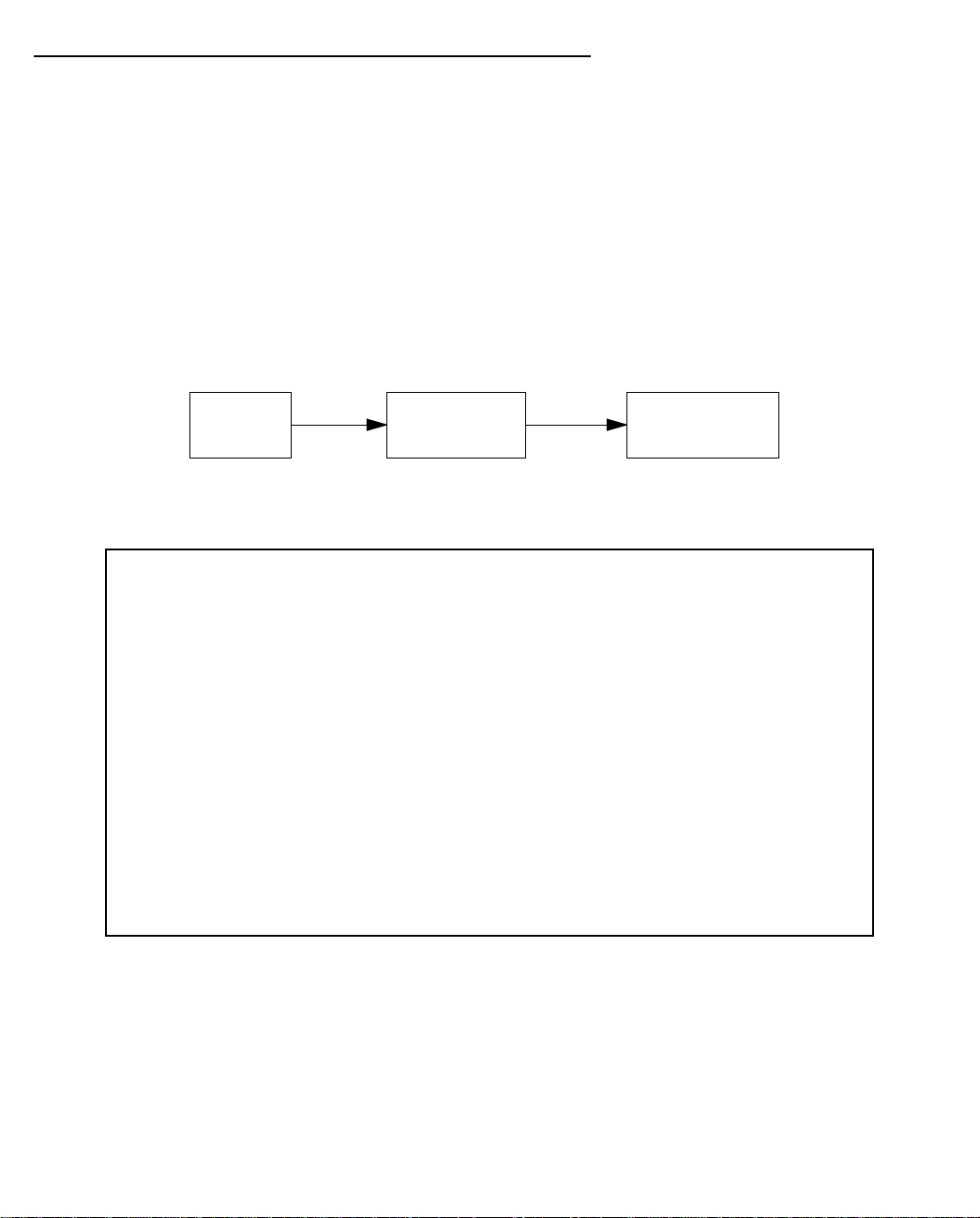
10-8 User’s Reference Guide
Connection Profiles
Since you will probably only have a single connection to your ISP over the SDSL link, you may not need to create
multiple connection profiles. Multiple connection profiles are useful on leased (unswitched) interfaces such as
SDSL only to support meshed WAN connections. If you do not intend to set up meshed WAN connections, you
do not need to create multiple connection profiles.
Connection profiles may be used to define the connection information for your WAN Auxiliary Port access.
Connection Profiles define the line and networking protocols necessary for the router to make a remote
connection. A connection profile is like an address book entry describing how the router is to get to a remote
site, or how to recognize and authenticate a remote user dialing in to the router. For example, to create a new
Connection Profile, you navigate to the WAN Configuration screen from the Main Menu, and select Add
Connection Profile.
Main
Menu
The Add Connection Profile screen appears.
Add Connection Profile
Profile Name: Profile 01
Profile Enabled: Yes
IP Enabled: Yes
IP Profile Parameters...
IPX Enabled: No
Data Link Encapsulation... PPP
Data Link Options...
ADD PROFILE NOW CANCEL
Return accepts * ESC cancels * Left/Right moves insertion point * Del deletes.
Configure a new Conn. Profile. Finished? ADD or CANCEL to exit.
WAN
Configuration
Add Connection
Profile
On a Netopia R7200 SDSL Router you can add up to 15 more connection profiles, for a total of 16, although
only one can be used at a time.
1. Select Profile Name and enter a name for this connection profile. It can be any name you wish. For
example: the name of your ISP.
2. Toggle the Profile Enabled value to Yes or No. The default is Yes.
3. Select IP Profile Parameters and press Return. The IP Profile Parameters screen appears.
Page 91

IP Setup and Network Address Translation 10-9
IP Profile Parameters
Address Translation Enabled: Yes
IP Addressing... Unnumbered
Local WAN IP Address: 0.0.0.0
Local WAN IP Mask: 0.0.0.0
Remote IP Address: 0.0.0.0
Remote IP Mask: 0.0.0.0
Filter Set...
Remove Filter Set
Receive RIP: Both
Transmit RIP: v2 (multicast)
Configure IP requirements for a remote network connection here.
4. Toggle or enter any IP parameters you require and return to the Add Connection Profile screen by pressing
Escape. For more information on NAT, see “Using Network Address Translation,” beginning on page 10-3.
For more information on IP addressing, see Appendix B, “Understanding IP Addressing.”
The Local WAN IP Address is displayed for numbered or NAT profiles. The Local WAN IP Mask is displayed
for numbered profiles. The Remote IP Address and Remote IP Mask are displayed for unnumbered profiles.
5. If you will be connecting with an IPX remote network, toggle IPX Enabled to Yes, and press Return.
Otherwise, accept the default No.
If you enable IPX routing, an IPX Profile Parameters menu item becomes available. Select IPX Profile
Parameters and press Return. The IPX Profile Parameters screen appears.
IPX Profile Parameters
Remote IPX Network: 00000000
Path Delay: 10
NetBios Packet Forwarding: Off
Incoming Packet Filter Set... <<NONE>>
Outgoing Packet Filter Set... <<NONE>>
Incoming SAP Filter Set... <<NONE>>
Outgoing SAP Filter Set... <<NONE>>
Periodic RIP Timer: 60
Periodic SAP Timer: 60
Configure IPX requirements for a remote network connection here.
6. T oggle or enter any IPX parameters you require and return to the Add Connection Profile screen by pressing
Escape. For more information, see “IPX Setup” on page 11-1.
Page 92

10-10 User’s Reference Guide
7. Select ADD PROFILE NOW and press Return. Your new connection profile will be added.
If you want to view the connection profiles in your router, return to the WAN Configuration screen, and
select Display/Change Connection Profile. The list of connection profiles is displayed in a scrolling pop-up
screen.
WAN Configuration
+-Profile Name---------------------IP Address----IPX Network-+
+------------------------------------------------------------+
| Easy Setup Profile 127.0.0.2 |
| Profile 02 0.0.0.0 |
| |
| |
| |
| |
| |
| |
| |
| |
| |
| |
| |
| |
| |
| |
+------------------------------------------------------------+
Up/Down Arrow Keys to select, ESC to dismiss, Return/Enter to Edit.
Network Address Translation guidelines
Observe the following guidelines when using Network Address Translation.
■ The router can export only one local IP address per UDP/TCP port, so you can have just one machine
available for a given service, such as one FTP server. However, some services, such as Web servers
(www-http servers), allow you to change the UDP/TCP port on both the server and client. With two different
UDP/TCP ports exported, you can have Web servers on two different IP hosts.
■ If you will be using multiple connection profiles, define the remote IP address of the most accessible
profile, such as that for your ISP, to the default IP gateway in the TCP/IP settings on users’ workstations.
That way, IP traffic not intended specifically for any of the remote networks will be routed through this
“preferred” profile.
■ Associate your primary Domain Name Server (DNS) with whichever profile is more accessible. If you
choose for neither profile to be “dial-on-demand,” you can associate a secondary DNS with the other
profile. See “IP setup,” below, for more information on these settings.
Page 93

IP setup
IP Setup and Network Address Translation 10-11
Main
Menu
System
Configuration
Network
Protocols
Setup
IP Setup
The IP Setup options screen is where you configure the Ethernet side of the Netopia R7200. The information
you enter here controls how the router routes IP traffic.
Consult your network administrator or Internet service provider to obtain the IP setup information (such as the
Ethernet IP address, Ethernet subnet mask, default IP gateway and Primary Domain Name Server IP address)
you will need before changing any of the settings in this screen. Changes made in this screen will take effect
only after the Netopia R7200 is reset.
To go to the IP Setup options screen, from the Main Menu, select System Configuration, then Network
Protocols Setup, and then IP Setup.
The IP Setup screen appears.
IP Setup
Ethernet IP Address: 192.128.117.162
Ethernet Subnet Mask: 255.255.255.0
Define Additional Subnets...
Default IP Gateway: 192.128.117.163
Primary Domain Name Server: 0.0.0.0
Secondary Domain Name Server: 0.0.0.0
Domain Name:
Receive RIP: Both
Transmit RIP: v2 (multicast)
Static Routes...
Address Serving Setup...
Exported Services...
Filter Sets...
Follow these steps to configure IP setup for your Netopia R7200:
■ Select Ethernet IP Address and enter the IP address for the Netopia R7200’s Ethernet port.
■ Select Ethernet Subnet Mask and enter the subnet mask for the Ethernet IP address that you entered in
the last step.
■ For unlimited-user models, if you desire multiple subnets select Define Additional Subnets. twelve-user
models do not offer this option. If you select this item you will be taken to the IP Subnets screen. This
screen allows you to define IP addresses and masks for additional subnets. See “IP subnets” on
page 10-15 for details.
Page 94

10-12 User’s Reference Guide
The Netopia R7200 SDSL Router supports multiple IP subnets on the Ethernet interface. Y ou may want to
configure multiple IP subnets to service more hosts than are possible with your primary subnet. It is not
always possible to obtain a larger subnet from your ISP. For example, if you already have a full Class C
subnet, your only option is multiple Class C subnets, since it is virtually impossible to justify a Class A or
Class B assignment. This assumes that you are not using NAT.
If you are using NAT, you can use the reserved Class A or Class B subnet.
■ Select Default IP Gateway and enter the IP address for a default gateway. This can be the address of any
major router accessible to the Netopia R7200.
A default gateway should be able to successfully route packets when the Netopia R7200 cannot recognize
the intended recipient’s IP address. A typical example of a default gateway is the ISP’s router.
■ Select Primary Domain Name Server and enter the IP address for a domain name server. The domain
name server matches the alphabetic addresses favored by people (for example, robin.hood.com) to the IP
addresses actually used by IP routers (for example, 163.7.8.202).
■ If a secondary DNS server is available, select Secondary Domain Name Server and enter its IP address.
The secondary DNS server is used by the Netopia R7200 when the primary DNS server is inaccessible.
Entering a secondary DNS is useful but not necessary.
■ Select Domain Name and enter your network’s domain name (for example, netopia.com). Netopia strongly
recommends that you enter a domain name.
■ Routing Information Protocol (RIP) is needed if there are IP routers on other segments of your Ethernet
network that the Netopia R7200 needs to recognize. If this is the case select Receive RIP and select v1,
v2, or Both from the pop-up menu. With Receive RIP set to v1, the Netopia R7200’s Ethernet port will
accept routing information provided by RIP packets from other routers that use the same subnet mask. Set
to v2, the Netopia R7200 will accept routing information provided by RIP packets from other routers that
use different subnet masks. Set to Both, the Netopia R7200 will accept information from either RIP v1 or
v2 routers.
■ If you want the Netopia R7200 to advertise its routing table to other routers via RIP, select Transmit RIP
and select v1, v2 (broadcast), or v2 (multicast) from the pop-up menu. With Transmit RIP v1 selected, the
Netopia R7200 will generate RIP packets only to other RIP v1 routers. With Transmit RIP v2 (broadcast)
selected, the Netopia R7200 will generate RIP packets to all other hosts on the network. With Transmit RIP
v2 (multicast) selected, the Netopia R7200 will generate RIP packets only to other routers capable of
recognizing RIP v2 packets.
■ Select Static Routes to manually configure IP routes. See the section “Static routes,” below.
■ If you select Address Serving Setup you will be taken to the IP Address Serving screen (see “IP address
serving” on page 10-21.) Since no two hosts can use the same IP address at the same time, make sure
that the addresses distributed by the Netopia R7200, and those that are manually configured are not the
same. Each method of distribution must have its own exclusive range of addresses to draw from.
■ Select Exported Services. The Exported Services screen appears with three options: Show/Change
Exports, Add Export, and Delete Export.
Page 95

IP Setup and Network Address Translation 10-13
Exported Services
(Local Port to IP Address Remapping)
Show/Change Exports...
Add Export...
Delete Export...
Return/Enter to configure UDP/TCP Port-to-IP Address redirection.
■ Select Add Export. The Add Exported Service screen appears.
Add Exported Service
Service...
Local Server's IP Address: 0.0.0.0
ADD EXPORT NOW CANCEL
Page 96

10-14 User’s Reference Guide
■ Select Service. A pop-up menu of services and ports appears.
Add Exported Service
+-Type------Port--+
+-----------------+
Service... | ftp 21 |
| telnet 23 |
| smtp 25 |
Local Server's IP Address: | tftp 69 |
| gopher 70 |
| finger 79 |
| www-http 80 |
| pop2 109 |
| pop3 110 |
| snmp 161 |
| timbuktu 407 |
| pptp 1723 |
| irc 6667 |
| Other... |
+-----------------+
ADD EXPORT NOW CANCEL
8. Select any of the services/ports and press Return to associate it with the address of a server on your local
area network. For example, if you select www-http 80, press Return, and type 10.0.0.2, the Netopia
R7200 redirects any incoming traffic destined for a Web server to address 10.0.0.2.
Some services such as Timbuktu require the export of multiple TCP ports. When you associate Timbuktu
with a local server (or Timbuktu host) all of the major Timbuktu services are exported, i.e., Observe,
Control, Send, and Exchange.
Note: If the TCP port of a service you want to use is not listed, you can add it by selecting Other... on the
pop-up menu.
Page 97

IP Setup and Network Address Translation 10-15
Press Escape when you are finished configuring exported services. You are returned to the IP Setup
screen.
IP Setup
Ethernet IP Address: 192.128.117.162
Ethernet Subnet Mask: 255.255.255.0
Define Additional Subnets...
Default IP Gateway: 192.128.117.163
Primary Domain Name Server: 0.0.0.0
Secondary Domain Name Server: 0.0.0.0
Domain Name:
Receive RIP: Both
Transmit RIP: v2 (multicast)
Static Routes...
Address Serving Setup...
Exported Services...
Filter Sets...
■ If you select Filter Sets you will be taken directly to the screen for configuring IP packet filters. For
information see “About filters and filter sets,” beginning on page 14-4.
IP subnets
The IP Subnets screen allows you to configure up to eight Ethernet IP subnets on unlimited-user models, one
“primary” subnet and up to seven secondary subnets, by entering IP address/subnet mask pairs:
IP Subnets
IP Address Subnet Mask
---------------- -------------- #1: 192.128.117.162 255.255.255.0
#2: 0.0.0.0 0.0.0.0
#3:
#4:
#5:
#6:
#7:
#8:
Page 98

10-16 User’s Reference Guide
Note: You need not use this screen if you have only a single Ethernet IP subnet. In that case, you can continue
to enter or edit the IP address and subnet mask for the single subnet on the IP Setup screen.
This screen displays up to eight rows of two editable columns, preceded by a row number between one and
eight. If you have eight subnets configured, there will be eight rows on this screen. Otherwise, there will be one
more row than the number of configured subnets. The last row will have the value 0.0.0.0 in both the IP
address and subnet mask fields to indicate that you can edit the values in this row to configure an additional
subnet. All eight row labels are always visible, regardless of the number of subnets configured.
■ To add an IP subnet, enter the Netopia R7200’s IP address on the subnet in the IP Address field in a
particular row and the subnet mask for the subnet in the Subnet Mask field in that row.
For example:
IP Subnets
IP Address Subnet Mask
---------------- -------------- #1: 192.128.117.162 255.255.255.0
#2: 192.128.152.162 255.255.0.0
#3: 0.0.0.0 0.0.0.0
#4:
#5:
#6:
#7:
#8:
■ T o delete a configured subnet, set both the IP address and subnet mask values to 0.0.0.0, either explicitly
or by clearing each field and pressing Return to commit the change. When a configured subnet is deleted,
the values in subsequent rows adjust up to fill the vacant fields.
Note that the subnets configured on this screen are tied to the address serving pools configured on the IP
Address Pools screen, and that changes on this screen may affect the IP Address Pools screen. In particular,
deleting a subnet configured on this screen will delete the corresponding address serving pool, if any, on the IP
Address Pools screen.
Page 99

IP Setup and Network Address Translation 10-17
If you have configured multiple Ethernet IP subnets, the IP Setup screen changes slightly:
IP Setup
Subnet Configuration...
Default IP Gateway: 192.128.117.163
Primary Domain Name Server: 0.0.0.0
Secondary Domain Name Server: 0.0.0.0
Domain Name:
Receive RIP: Both
Transmit RIP: v2 (multicast)
Static Routes...
Address Serving Setup...
Exported Services...
Filter Sets...
The IP address and Subnet mask items are hidden, and the Define Additional Subnets... item becomes Subnet
Configuration.... If you select Subnet Configuration, you will return to the IP Subnets screen that allows you to
define IP addresses and masks for additional Ethernet IP subnets.
Static routes
Static routes are IP routes that are maintained manually. Each static route acts as a pointer that tells the
Netopia R7200 how to reach a particular network. However, static routes are used only if they appear in the IP
routing table, which contains all of the routes used by the Netopia R7200 (see “IP routing table” on page 13-8).
Static routes are helpful in situations where a route to a network must be used and other means of finding the
route are unavailable. For example, static routes are useful when you cannot rely on RIP.
To go to the Static Routes screen, select Static Routes in the IP Setup screen and press Return.
Page 100

10-18 User’s Reference Guide
The Static Routes screen will appear.
Static Routes
Display/Change Static Route...
Add Static Route...
Delete Static Route...
Configure/View/Delete Static Routes from this and the following Screens.
Viewing static routes
To display a view-only table of static routes, select Display/Change Static Route. The table shown below will
appear.
+-Dest. Network---Subnet Mask-----Next Gateway----Priority-Enabled-+
+------------------------------------------------------------------+
| 0.0.0.0 0.0.0.0 163.176.8.1 Low Yes |
| |
| |
| |
| |
| |
| |
| |
| |
| |
| |
| |
| |
| |
| |
+------------------------------------------------------------------+
Select a Static Route to modify.
The table has the following columns:
Dest. Network: The network IP address of the destination network.
 Loading...