

Page 1

Netopia™ R5000 Series Routers
R5100 Serial Router
R5200 DDS Router
R5300 T1 Router
User’s Reference Guide
Page 2

Copyright
©2000, Netopia, Inc.,
All rights reserved. Printed in the U.S.A.
This manual and any associated artwork, software, and product designs are copyrighted with
all rights reserved. Under the copyright laws such materials may not be copied, in whole or
part, without the prior written consent of Netopia, Inc. Under the law, copying includes
translation to another language or format.
Netopia, Inc.
2470 Mariner Square Loop
Alameda, CA 94501-1010
U.S.A.
Part Number
For additional copies of this electronic manual, order Netopia part number 6160016-PF-02
Printed Copies
For printed copies of this manual, order Netopia part number TER5000/Doc
(P/N 6160016-00-02)
Page 3

CCCCoooonnnntttteeeennnnttttss
ss
Welcome to the Netopia R5000 Series Router
be your single source for information about your Netopia R5000 Series Router. It is intended to be
viewed on-line, using the powerful features of the Adobe Acrobat Reader. The information display
has been designed to present the maximum information in the minimum space on your screen. You
can keep this document open while you perform any of the procedures described and find useful
information about the procedure you are performing.
This Table of Contents page you are viewing consists of hypertext links to the chapters and
headings listed. If you are viewing this on-line, just click any link below to go to that heading.
User’s Reference Guide
. This guide is designed to
Part I: Getting Started
Chapter 1 — Introduction..........................................................1-1
Overview....................................................................... 1-1
Features and capabilities ............................................... 1-1
How to use this guide .................................................... 1-2
Chapter 2 — Setting Up Internet Services .................................2-1
Finding an Internet service provider................................. 2-1
Unique requirements............................................ 2-2
Pricing and support.............................................. 2-2
Endorsements ..................................................... 2-2
Deciding on an ISP account............................................ 2-2
Setting up a Netopia R5000 Series account........... 2-2
Obtaining an IP address........................................ 2-2
Obtaining information from the ISP.................................. 2-3
Local LAN IP address information to obtain............ 2-3
G
B
Chapter 3 — Making the Physical Connections..........................3-1
Find a location............................................................... 3-1
What you need .............................................................. 3-2
Connect the router......................................................... 3-3
R5100 Serial....................................................... 3-3
R5200 DDS and R5300 T1................................... 3-3
Identify the connectors......................................... 3-4
Attach the cables................................................. 3-4
Netopia R5000 Series Router status lights...................... 3-5
Chapter 4 — Connecting to Your Local Area Network.................4-1
Overview....................................................................... 4-1
Page 4

iv User’s Reference Guide
Readying computers on your local network....................... 4-1
Connecting to an Ethernet network.................................. 4-3
10Base-T............................................................. 4-3
Adding an external modem ............................................. 4-4
Connecting to a LocalTalk network ................................. 4-5
Chapter 5 — Setting up your Router with the SmartStart Wizard 5-1
Before running SmartStart ............................................. 5-2
Setting up your Router with the SmartStart Wizard........... 5-3
SmartStart Wizard configuration screens ............... 5-3
Easy option.......................................................... 5-4
Advanced option .................................................. 5-5
Sharing the Connection.................................................. 5-6
Configuring TCP/IP on Windows 95, 98, or NT
computers........................................................... 5-6
Configuring TCP/IP on Macintosh computers........ 5-10
Chapter 6 — Console-Based Management.................................6-1
Connecting through a Telnet session............................... 6-2
Configuring Telnet software ................................... 6-3
Connecting a console cable to your router ....................... 6-3
Navigating through the console screens .......................... 6-4
Chapter 7 — Easy Setup...........................................................7-1
Easy Setup console screens........................................... 7-1
Accessing the Easy Setup console screens............ 7-1
The Serial Line Easy Setup configuration screen..... 7-3
The T1 Line configuration screen........................... 7-4
The DDS Line configuration screen........................ 7-5
Easy Setup Profile screen ..................................... 7-6
IP Easy Setup ...................................................... 7-7
Easy Setup Security Configuration ......................... 7-8
Page 5

Contents v
Part II: Advanced Configuration
Chapter 8 — WAN and System Configuration .............................8-1
WAN configuration.......................................................... 8-1
Line configuration for a Serial line ......................... 8-2
Line configuration for a DDS line ........................... 8-3
Line configuration for a T1 line.............................. 8-4
Configuring Frame Relay................................................. 8-6
Easy Setup Frame Relay screens........................... 8-6
WAN Configuration Frame Relay screens................ 8-7
Frame Relay configuration..................................... 8-8
Frame Relay DLCI configuration........................... 8-10
Creating a new Connection Profile................................. 8-14
The default profile........................................................ 8-20
IP parameters (default profile) screen .................. 8-21
IPX parameters (default profile) screen ................ 8-22
Scheduled connections (switched async only) ................ 8-23
Viewing scheduled connections........................... 8-24
Adding a scheduled connection........................... 8-25
Set Weekly Schedule.......................................... 8-26
Set Once-Only Schedule...................................... 8-27
Modifying a scheduled connection....................... 8-28
Deleting a scheduled connection......................... 8-28
Connection accounting screens (switched async only) .... 8-29
System configuration screens ...................................... 8-32
Navigating through the system configuration screens...... 8-32
System configuration features............................. 8-33
Network protocols setup..................................... 8-34
Filter sets (firewalls)........................................... 8-34
IP address serving ............................................. 8-34
Date and time.................................................... 8-34
Console configuration......................................... 8-35
SNMP (Simple Network Management Protocol)..... 8-36
G
Page 6

vi User’s Reference Guide
Security............................................................. 8-36
Upgrade feature set ........................................... 8-36
Logging ............................................................. 8-36
Installing the Syslog client .................................. 8-37
Chapter 9 — IP Setup and Network Address Translation ............9-1
Network Address Translation features ............................. 9-1
Using Network Address Translation................................. 9-3
Associating port numbers with nodes.................... 9-7
Advanced IP/IPX router configuration options................... 9-8
Connection Profiles........................................................ 9-8
Network Address Translation guidelines............... 9-11
IP setup...................................................................... 9-12
IP subnets......................................................... 9-16
Static routes...................................................... 9-18
IP address serving....................................................... 9-22
IP Address Pools................................................ 9-25
DHCP NetBIOS Options....................................... 9-27
MacIP (KIP forwarding) setup .............................. 9-29
Chapter 10 — IPX Setup.........................................................10-1
IPX features ................................................................ 10-1
IPX definitions ............................................................. 10-1
Internetwork Packet Exchange (IPX) ..................... 10-1
IPX address....................................................... 10-2
Socket .............................................................. 10-2
Routing Information Protocol (RIP) ....................... 10-2
Service Advertising Protocol (SAP)....................... 10-2
NetBIOS............................................................ 10-3
IPX spoofing....................................................... 10-3
IPX setup screen ......................................................... 10-3
IPX routing tables ........................................................ 10-5
Page 7

Contents vii
Chapter 11 — AppleTalk Setup................................................11-1
AppleTalk networks ...................................................... 11-1
AppleTalk protocol.............................................. 11-1
MacIP................................................................ 11-3
AURP................................................................. 11-3
Routers and seeding .......................................... 11-3
Installing AppleTalk ...................................................... 11-4
Configuring AppleTalk ................................................... 11-6
EtherTalk setup.................................................. 11-6
LocalTalk setup ................................................. 11-7
AURP setup ....................................................... 11-8
Chapter 12 — Monitoring Tools...............................................12-1
Quick View status overview .......................................... 12-1
General status................................................... 12-2
Current status ................................................... 12-3
Status lights...................................................... 12-3
Statistics & Logs......................................................... 12-4
General Statistics .............................................. 12-5
Event histories ............................................................ 12-6
Routing tables............................................................. 12-8
Served IP Addresses.................................................. 12-11
System Information.................................................... 12-13
SNMP....................................................................... 12-13
The SNMP Setup screen................................... 12-14
SNMP traps..................................................... 12-15
T1 Diagnostics .......................................................... 12-17
T1 Line Statistics and Diagnostics screen.......... 12-17
Web-based monitoring................................................ 12-20
System Information page.................................. 12-20
Frame Relay Statistics page.............................. 12-22
Connection Status page.................................... 12-23
Connect/Disconnect page................................. 12-24
G
Page 8

viii User’s Reference Guide
Router Budget Configuration page ..................... 12-25
Connection Budgets page................................. 12-26
Connection Budget Configuration page............... 12-27
Budget Statistics page ..................................... 12-28
Event History pages ......................................... 12-29
Chapter 13 — Security ...........................................................13-1
Suggested security measures....................................... 13-1
User accounts............................................................. 13-1
Dial-in console access.................................................. 13-3
Enable SmartStart/SmartView/Web server ................... 13-4
Telnet access .............................................................. 13-4
About filters and filter sets ........................................... 13-4
What’s a filter and what’s a filter set?.................. 13-4
How filter sets work............................................ 13-5
How individual filters work................................... 13-7
Design guidelines............................................. 13-11
Working with IP filters and filter sets............................ 13-12
Adding a filter set............................................. 13-13
Adding filters to a filter set................................ 13-14
Viewing filter sets............................................. 13-18
Modifying filter sets.......................................... 13-19
Deleting a filter set........................................... 13-19
A sample IP filter set........................................ 13-19
IPX filters .................................................................. 13-23
IPX packet filters.............................................. 13-24
IPX packet filter sets ........................................ 13-25
IPX SAP filters.................................................. 13-27
IPX SAP filter sets ............................................ 13-29
Firewall tutorial.......................................................... 13-31
General firewall terms ...................................... 13-31
Basic IP packet components............................. 13-31
Basic protocol types......................................... 13-31
Page 9

Contents ix
Firewall design rules......................................... 13-32
Filter basics..................................................... 13-35
Example filters................................................. 13-36
Chapter 14 — Utilities and Diagnostics...................................14-1
Ping............................................................................ 14-2
Trace Route................................................................. 14-5
Telnet client................................................................. 14-6
Disconnect Telnet console session ............................... 14-7
Factory defaults........................................................... 14-7
Transferring configuration and firmware files with TFTP.... 14-8
Updating firmware .............................................. 14-8
Downloading configuration files ........................... 14-9
Uploading configuration files ............................. 14-10
Transferring configuration and firmware files with
XMODEM................................................................... 14-10
Updating firmware ............................................ 14-11
Downloading configuration files ......................... 14-12
Uploading configuration files ............................. 14-12
Restarting the system................................................ 14-13
G
Part III: Appendixes
Appendix A — Troubleshooting..................................................A-1
Configuration problems .................................................. A-1
Console connection problems ............................... A-2
Network problems................................................ A-2
How to reset the router to factory defaults ...................... A-3
Power outages............................................................... A-3
Technical support .......................................................... A-4
How to reach us................................................... A-4
Appendix B — Understanding IP Addressing ..............................B-1
What is IP?.................................................................... B-1
About IP addressing....................................................... B-1
Page 10

x User’s Reference Guide
Subnets and subnet masks .................................. B-2
Example: Using subnets on a Class C IP internet.... B-3
Example: Working with a Class C subnet................ B-5
Distributing IP addresses ............................................... B-5
Technical note on subnet masking......................... B-6
Configuration ....................................................... B-7
Manually distributing IP addresses ........................ B-8
Using address serving.......................................... B-8
Tips and rules for distributing IP addresses............ B-9
Nested IP subnets....................................................... B-11
Broadcasts.................................................................. B-13
Packet header types........................................... B-13
Appendix C — Understanding Netopia NAT Behavior...................C-1
Network configuration..................................................... C-1
Background................................................................... C-1
Exported services................................................ C-5
Important notes................................................... C-6
Configuration................................................................. C-7
Summary...................................................................... C-8
Appendix D — Binary Conversion Table......................................D-1
Appendix E — Further Reading..................................................E-1
Appendix F — Technical Specifications and Safety Information...F-1
Pinouts for Auxiliary port modem cable............................ F-1
Description.................................................................... F-3
Power requirements ............................................. F-3
Environment ........................................................ F-3
Software and protocols......................................... F-3
Agency approvals........................................................... F-4
Regulatory notices ............................................... F-4
Important safety instructions ................................ F-6
Glossary..................................................................................GL-1
Page 11

Contents xi
Index ..................................................................................Index-1
Limited Warranty and Limitation of Remedies................................1
G
Page 12

xii User’s Reference Guide
Page 13

PPPPaaaarrrrtttt IIII:::: GGGGeeeettttttttiiiinnnngggg SSSSttttaaaarrrrtttteeeedd
dd
Page 14

User’s Reference Guide
Page 15

Introduction 1-1
CCCChhhhaaaapppptttteeeerrrr 11
IIIInnnnttttrrrroooodddduuuuccccttttiiiioooonn
OOOOvvvveeeerrrrvvvviiiieeeeww
The Netopia R5000 Series Router line consists of the R5100 Serial Router, the R5200 DDS Router, and the
R5300 T1 Router. Each is a full-featured, stand-alone, multiprotocol router for connecting diverse local area
networks (LANs) to the Internet and other remote networks.
Netopia's high-speed, leased line routers provide Internet service at 56K DDS, Fractional T1/E1, and T1/E1
speeds to give any branch, small-to-medium-sized office, or school a full-time presence on the Internet. With
built-in ease of use features, Netopia R5000 Series Routers provide an intuitive way to connect your network to
the Internet. As with all Netopia Routers, the leased line models come packaged as a complete solution,
including the necessary software, cables, and services to get you quickly connected to the Internet or corporate
Intranet.
Once your Netopia R5000 Series Router is connected to your computer, and your account is activated by your
frame and Internet service providers, you will have a clean, high-speed connection to the outside world.
This section covers the following topics:
■
“Features and capabilities” on page 1-1
■
“How to use this guide” on page 1-2
11
nn
ww
FFFFeeeeaaaattttuuuurrrreeeessss aaaannnndddd ccccaaaappppaaaabbbbiiiilllliiiittttiiiieeeess
Netopia R5000 Series Routers provide the following features:
■
From 56K to 2.0 Mbps Serial, 56K DDS, and Fractional T1/T1 Models
■
Built-in 8-port Ethernet hub with uplink port to easily connect the router to workstations or other 10Base-T
hubs
Built-in basic firewall with IP or IPX packet filtering
■
■
Support for Frame Relay, PPP, and Cisco-HDLC encapsulation
■
SmartMatch automatic detection of Frame Relay parameters
Support for IP and IPX routing for Internet and intranet connectivity
■
■
IP address serving (over Ethernet or a WAN link) that allows local or remote network nodes to acquire an IP
address automatically and dynamically from a designated pool of available addresses
■
Continuous-availability networking, eliminating dialing and providing lower, more predictable transmission
ss
Page 16

1-2 User’s Reference Guide
costs
Status lights (LEDs) for easy monitoring and troubleshooting
■
■
Support for console-based management over Telnet or serial cable connection
■
Support for remote configuration by your reseller, your network administrator, or technicians at Netopia,
Inc., via external modem or via IP network
Wall-mountable, bookshelf (side-stackable), or desktop-stackable design for efficient space usage
■
■
Network Address Translation (NAT) to protect the identity of LAN IP addresses from would-be intruders by
representing all LAN IP addresses to the Internet or remote network as a single address. Design allows
multiple servers (Web, mail, ftp, etc.) on the LAN to be accessible to the Internet.
AppleTalk support (available as a separate add-on AppleTalk kit, including a firmware feature set
■
enhancement and custom HD-15 dual RJ-11 PhoneNET® connector), allowing for LocalTalk-to-Ethernet
routing, assigning IP addresses to Macintosh users (MacIP), IP functionality for LocalTalk users, and AURP
tunneling for connectivity between remote AppleTalk networks
Web-based monitoring of router status and budget management through a selection of forms in a
■
web-browser. (Internet browsers such as Netscape Navigator and Microsoft’s Internet Explorer are supplied
on the Netopia CD.)
■
Near-term firmware upgrade will support built-in secure Virtual Private Networks (VPN) and Multi-NAT, a NAT
implementation that allows a combination of one-to-one and one-to-many NAT on the same physical or
tunneled connection.
HHHHoooowwww ttttoooo uuuusssseeee tttthhhhiiiissss gggguuuuiiiiddddee
ee
This guide is designed to be your single source for information about your Netopia R5000 Series Router. It is
intended to be viewed on-line, using the powerful features of the Adobe Acrobat Reader. The information display
has been deliberately designed to present the maximum information in the minimum space on your screen. You
can keep this document open while you perform any of the procedures described and find useful information
about the procedure you are performing.
If you prefer to work from hard copy rather than on-line documentation, you can also print out all of the manual,
or individual sections. The pages are formatted to print on standard 8 1/2 by 11 inch paper. We recommend
that you print on three-hole punched paper, so you can put the pages in a binder for future reference. For your
convenience, a printed copy can be purchased from Netopia. Order part number TER5000/Doc.
This guide is organized into chapters describing the Netopia R5000 Series’s advanced features. You may want
to read each chapter’s introductory section to familiarize yourself with the various features available.
Use the guide’s table of contents and index to locate informational topics.
Page 17

Setting Up Internet Services 2-1
CCCChhhhaaaapppptttteeeerrrr 22
SSSSeeeettttttttiiiinnnngggg UUUUpppp IIIInnnntttteeeerrrrnnnneeeetttt SSSSeeeerrrrvvvviiiicccceeeess
This chapter describes how to obtain and set up Internet services.
This section covers the following topics:
■
“Finding an Internet service provider” on page 2-1
“Deciding on an ISP account” on page 2-2
■
“Obtaining information from the ISP” on page 2-3
■
Note:
Some companies act as their own ISP. For example, some organizations have branch offices that can
use the Netopia R5000 Series to access the Internet via the main office. If you install the Netopia R5000
Series in this type of environment, refer to the following sections for specific information you must receive from
the network administrator to configure the Netopia R5000 Series properly.
FFFFiiiinnnnddddiiiinnnngggg aaaannnn IIIInnnntttteeeerrrrnnnneeeetttt sssseeeerrrrvvvviiiicccceeee pppprrrroooovvvviiiiddddeeeerr
Internet access is available from Internet service providers (ISPs). Typically, there are several ISPs in each
area. To locate ISPs in your area, consult your telephone book, local computer magazines, the business section
of a local newspaper, or the following URL on the Internet: ‘http://www.thelist.com’. Also see Netopia’s home
page at ‘http://www.netopia.com’ for a list of special programs and promotions for Netopia customers.
22
ss
rr
If your area has more than one ISP, the following considerations may help you decide which ISP is best suited
for your requirements.
Use an ISP that provides Internet access through a digital line.
Digital line access combinations
Type of Service Data Rate Speed Datalink Protocol
DDS/ADN • 56 - 64 kbps PPP, HDLC, Frame Relay
T1 • 56 kbps - 1.544 mbps (Fractional T1)
• 1.544 mbps (T1)
E1 • 64 kbps - 2.0 mbps PPP, HDLC, Frame Relay
PPP, HDLC, Frame Relay
Page 18

2-2 User’s Reference Guide
UUUUnnnniiiiqqqquuuueeee rrrreeeeqqqquuuuiiiirrrreeeemmmmeeeennnnttttss
Make sure the ISP can meet any unique requirements you may have, such as:
■
Dynamic or static IP addressing
IP address range
■
■
Custom domain name
■
Multiple e-mail addresses
Web site hosting
■
E-commerce
■
■
VPN support
PPPPrrrriiiicccciiiinnnngggg aaaannnndddd ssssuuuuppppppppoooorrrrtttt
Compare pricing, service, and technical support service among various ISPs.
EEEEnnnnddddoooorrrrsssseeeemmmmeeeennnnttttss
Consider recommendations from colleagues and reviews in publications. Netopia lists Netopia Certified ISPs on
our Web site at
ss
http://www.netopia.com
DDDDeeeecccciiiiddddiiiinnnngggg oooonnnn aaaannnn IIIISSSSPPPP aaaaccccccccoooouuuunnnntt
ss
.
tt
Your ISP may offer various Internet access account plans. Typically, these plans vary by usage charges and the
number of host IP addresses supplied. Evaluate your networking needs and discuss them with your ISP before
deciding on a plan for your network.
SSSSeeeettttttttiiiinnnngggg uuuupppp aaaa NNNNeeeettttooooppppiiiiaaaa RRRR5555000000000000 SSSSeeeerrrriiiieeeessss aaaaccccccccoooouuuunnnntt
Check whether your ISP has the Netopia R5000 Series on its list of supported products that have been tested
with a particular configuration. If the ISP does not have the Netopia R5000 Series on such a list, describe the
Netopia R5000 Series in as much detail as needed, so your ISP account can be optimized. As appropriate, refer
your ISP to Netopia’s Web site, http://www.netopia.com, for more information.
OOOObbbbttttaaaaiiiinnnniiiinnnngggg aaaannnn IIIIPPPP aaaaddddddddrrrreeeessssss
Typically, each network computer that requires Internet access requires its own unique IP address. If some or
all network computers require simultaneous Internet access, obtain a block of IP host addresses large enough
for each computer to have its own address, plus one for the Netopia R5000 Series.
Consider expected growth in your network when deciding on the number of addresses to obtain. Alternatively,
you can use the Network Address Translation feature such that you require just one address from your service
provider.
ss
tt
Page 19

Setting Up Internet Services 2-3
OOOObbbbttttaaaaiiiinnnniiiinnnngggg iiiinnnnffffoooorrrrmmmmaaaattttiiiioooonnnn ffffrrrroooommmm tttthhhheeee IIIISSSSPP
PP
After your account is set up, the ISP should send you the IP parameter information that will help you configure
the Netopia R5000 Series.
LLLLooooccccaaaallll LLLLAAAANNNN IIIIPPPP aaaaddddddddrrrreeeessssssss iiiinnnnffffoooorrrrmmmmaaaattttiiiioooonnnn ttttoooo oooobbbbttttaaaaiiiinn
nn
Your ISP will need to provide you with the following information:
■
The default gateway IP address (same as remote IP address in most cases)
Local WAN IP address and subnet mask
■
■
Primary and secondary domain name server (DNS) IP addresses
■
Domain name (usually the same as the ISP’s domain name unless you have registered for your own
individual domain name)
Note:
The default gateway, WAN address and mask, DNS, and domain name are all obtainable via WAN DHCP,
if your ISP supports it.
WWWWiiiitttthhhh NNNNeeeettttwwwwoooorrrrkkkk AAAAddddddddrrrreeeessssssss TTTTrrrraaaannnnssssllllaaaattttiiiioooonn
nn
If you are using Network Address Translation you should obtain the following:
■
If you are connecting to a remote site using Network Address Translation on your router, your provider will
not define the IP address information on your local LAN. You can define this information based on an IP
configuration that may already be in place for the existing network. Alternatively, you can use the default IP
address range used by the router, 192.168.1.x.
WWWWiiiitttthhhhoooouuuutttt NNNNeeeettttwwwwoooorrrrkkkk AAAAddddddddrrrreeeessssssss TTTTrrrraaaannnnssssllllaaaattttiiiioooonn
nn
If you are not using Network Address Translation, you will need to obtain all of the local LAN IP address
information from your ISP.
If you are not using Network Address Translation you should obtain:
The number of Ethernet IP host addresses available with your account and the first usable IP host address
■
in the address block
■
The Ethernet IP address for your Netopia R5000 Series
The Ethernet IP subnet mask address for your Netopia R5000 Series
■
Page 20

2-4 User’s Reference Guide
Page 21

Making the Physical Connections 3-1
CCCChhhhaaaapppptttteeeerrrr 33
MMMMaaaakkkkiiiinnnngggg tttthhhheeee PPPPhhhhyyyyssssiiiiccccaaaallll CCCCoooonnnnnnnneeeeccccttttiiiioooonnnnss
This section tells you how to make the physical connections to your Netopia R5000 Series Router. This section
covers the following topics:
■
“Find a location” on page 3-1
■
“What you need” on page 3-2
“Connect the router” on page 3-3
■
■ “Netopia R5000 Series Router status lights” on page 3-5
FFFFiiiinnnndddd aaaa llllooooccccaaaattttiiiioooonn
When choosing a location for the Netopia Router, consider:
■ Available space and ease of installation
■ Physical layout of the building and how to best use the physical space available for connecting your Netopia
Router to the LAN
■ Available wiring and jacks
■ Distance from the point of installation to the next device (length of cable or wall wiring)
33
ss
nn
■ Ease of access to the front of the unit for configuration and monitoring
■ Ease of access to the back of the unit for checking and changing cables
■ Cable length and network size limitations when expanding networks
For small networks, install the Netopia R5000 Series Router near one of the LANs. For large networks, you can
install the Netopia R5000 Series Router in a wiring closet or a central network administration site.
Page 22

3-2 User’s Reference Guide
WWWWhhhhaaaatttt yyyyoooouuuu nnnneeeeeeeedd
dd
Locate all items that you need for the installation.
Included in your router package are:
■ The Netopia R5000 Series Router
■ A power adapter and cord with a mini-DIN8 connector
■ One RJ-45 Ethernet cable
■ One RJ-45 Telco (or Line) cable
■ A dual DB-9 and mini-DIN8 to DB-9 console cable (for a PC or a Macintosh)
■ An X.21 DTE cable or a V.35 DTE cable (for a Serial model only)
■ The Netopia CD containing an Internet browser, Adobe Acrobat Reader for Windows and Macintosh, ZT erm
terminal emulator software and NCSA Telnet for Macintosh, this User’s Reference Guide, and other
documentation
You will need:
■ A Windows 95 or 98–based PC or a Macintosh computer with Ethernet connectivity for configuring the
Netopia R5000 Series Router. This may be built-in Ethernet or an add-on card, with TCP/IP installed and
configured. See “Before running SmartStart” on page 5-2.
■ A wall outlet wired for a T1 (for the R5300) or DDS (for the R5200) connection or a connection to an
external CSU/DSU or modem (for the R5100).
Page 23
Making the Physical Connections 3-3
CCCCoooonnnnnnnneeeecccctttt tttthhhheeee rrrroooouuuutttteeeerr
rr
Identify the connectors and switches on the back panel and attach the necessary Netopia Router cables.
RRRR5555111100000000 SSSSeeeerrrriiiiaaaall
ll
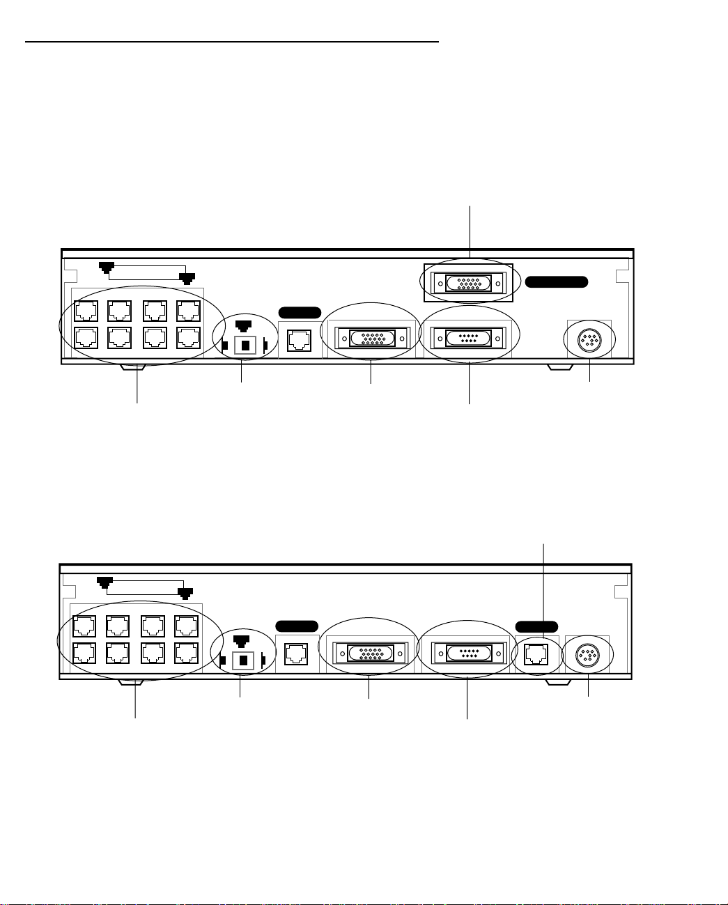
The figure below displays the back of the Netopia R5100 Serial Router.
Netopia R5100 back panel
Serial Line port
8
Ethernet
8 port Ethernet hub
1
Normal
1
Uplink
Crossover switch
Line 2
Auxiliary
Auxiliary port
Console
Console port
Line 1 - Serial
Power
Power port
RRRR5555222200000000 DDDDDDDDSSSS aaaannnndddd RRRR5555333300000000 TTTT11
11
The figure below displays the back of the Netopia R5200 DDS or R5300 T1 Router.
Netopia R5200/5300 back panel
Line port
8
Ethernet
8 port Ethernet hub
1
Normal
1
Uplink
Crossover switch
Line 2
Auxiliary Console Power
Line 1
Auxiliary port
Console port
Power port
Note: For simplicity, the remainder of this manual uses the figure above to illustrate connections.
Page 24

3-4 User’s Reference Guide
IIIIddddeeeennnnttttiiiiffffyyyy tttthhhheeee ccccoooonnnnnnnneeeeccccttttoooorrrrss
The following table describes all of the Netopia R5000 Series Router back panel ports.
Port Description
Power port A mini-DIN8 power adapter cable connection.
Serial Line 1 port
(R5100 Serial router only)
Line ports A telephone-style jack labeled “Line 1” for your T1 or DDS WAN connection. Use
Console port A DB-9 console port for a direct serial connection to the management console
Auxiliary port An HD-15 auxiliary port for attaching an external modem for remote
Crossover switch A crossover switch with Normal and Uplink positions. If you use Ethernet Port
8-port Ethernet hub Eight Ethernet jacks. You will use one of these to configure the Netopia R5000
ss
A DB-15 serial port labelled Line 1 - Serial for your external CSU/DSU or modem
connection.
the “Line 1" port, NOT “Line 2." The Line port is not used for a Serial
connection.
screens. You can use this if you are unable to connect to the console screens
using Telnet over the network. See “Connecting a console cable to your router”
on page 6-3.
management or the optional AppleTalk kit.
#1 for a direct Ethernet connection between a computer and the router, set the
switch to the Normal position. If you are connecting the router to an Ethernet
hub, use Ethernet port #1 on the router and set the switch to the Uplink
position.
Series Router. For a new installation, use the Ethernet connection. Alternatively,
you can use the console connection to run console-based management using a
direct serial connection. Y ou can either connect your computer directly to any of
the Ethernet ports on the router, or connect both your computer and the router
to an existing Ethernet hub on your LAN.
AAAAttttttttaaaacccchhhh tttthhhheeee ccccaaaabbbblllleeeess
1. Connect an RJ-45 Ethernet cable to any of the Ethernet ports on the router and the Ethernet port on your
computer.
2. R5100 Serial: Connect the special DB-15 Serial cable to the Serial Line 1 port and to your external
CSU/DSU or modem.
or
R5200 DDS or R5300 T1: Connect one end of an RJ-45 T elco cable to the Line 1 port and the other end to
your T1 or DDS wall outlet.
3. Connect the mini-DIN8 connector from the power adapter to the power port, and plug the other end into an
electrical outlet.
(If you are connecting the router to an existing Ethernet hub, use Ethernet port #1 on the router and set the
crossover switch to the Uplink position.)
You should now have the power adapter plugged in, the Ethernet cable connected between the router and
your computer, and either the Serial cable connected to a CSU/DSU or modem (R5100 Serial) or the Line
cable connected between the router and the Line wall outlet (R5200 DDS and R5300 T1).
ss
Page 25
Making the Physical Connections 3-5
NNNNeeeettttooooppppiiiiaaaa RRRR5555000000000000 SSSSeeeerrrriiiieeeessss RRRRoooouuuutttteeeerrrr ssssttttaaaattttuuuussss lllliiiigggghhhhttttss
ss
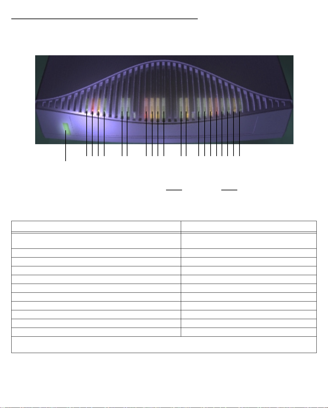
The figure below represents the Netopia R5000 Series Router status light (LED) panel.
Netopia R5000 Series Router LED front panel
2 3 4 5 6 7 8 9 10 11 12 13 14 15 16171819 20 21
1
Link/Receive
Power
Ready
Channel 1
Management
WAN 1 WAN 2 Ethernet
Console
Channel 2
Auxiliary
Management
Ready
Channel 1
Channel 2
Traffic
Collision
The following table summarizes the meaning of the various LED states and colors:
When this happens... the LEDs...
The corresponding line passes supervisory traffic between
2 flashes yellow.
the WAN and the Netopia R5000 Series Router
The WAN interface is operational 3 is green.
The line is unavailable 3 flashes red.
The WAN has carrier 4 is green.
Data is transmitted or received on the WAN 4 flashes yellow.
Carrier is asserted 6 and 7 are green.
Data is transmitted or received 6 and 7 flash yellow.
Data is transmitted or received by the Ethernet controller 12 flashes yellow.
The Ethernet interface detects a collision 13 flashes red.
Link is detected 14 though 21 are solid green.
Data are received on their respective ports 14 though 21 flash green.
Note: Channel 2 (#5) and WAN 2 (#8 through #11) are unused, since traffic is carried only on WAN channel
1. Also, Console carrier (6) is ignored if the console is not configured for a remote modem.
Page 26

3-6 User’s Reference Guide
Page 27

Connecting to Your Local Area Network 4-1
CCCChhhhaaaapppptttteeeerrrr 44
CCCCoooonnnnnnnneeeeccccttttiiiinnnngggg ttttoooo YYYYoooouuuurrrr LLLLooooccccaaaallll AAAArrrreeeeaaaa NNNNeeeettttwwwwoooorrrrkk
This chapter describes how to physically connect the Netopia R5000 Series to your local area network (LAN).
Before you proceed, make sure the Netopia R5000 Series is properly configured. You can customize the
router’s configuration for your particular LAN requirements using console-based management (see
“Console-Based Management” on page 6-1).
This section covers the following topics:
■ “Overview” on page 4-1
■ “Readying computers on your local network” on page 4-1
■ “Connecting to an Ethernet network” on page 4-3
■ “Adding an external modem” on page 4-4
■ “Connecting to a LocalTalk network” on page 4-5
OOOOvvvveeeerrrrvvvviiiieeeeww
You can connect the Netopia R5000 Series to an IP or IPX network that uses Ethernet.
If you have purchased the AppleTalk feature expansion kit, you can also connect the router to a LocalTalk
network that uses PhoneNET cabling.
44
kk
ww
Additionally, on the R5200 and R5300 models you can connect an external modem for remote management.
See “Adding an external modem” on page 4-4.
Caution!
Before connecting the Netopia R5000 Series to any AppleTalk LANs that contain other AppleTalk routers, you
should read “Routers and seeding” on page 11-3.
See the later sections in this chapter for details on how to connect the Netopia R5000 Series to different types
of networks.
RRRReeeeaaaaddddyyyyiiiinnnngggg ccccoooommmmppppuuuutttteeeerrrrssss oooonnnn yyyyoooouuuurrrr llllooooccccaaaallll nnnneeeettttwwwwoooorrrrkk
PC and Macintosh computers must have certain components installed before they can communicate through
the Netopia R5000 Series. The following illustration shows the minimal requirements for a typical PC or
Macintosh computer.
kk
Page 28

4-2 User’s Reference Guide
Application software
TCP/IP stack
Ethernet/EtherTalk/LocalTalk Driver
Your PC
or Macintosh
computer
To the Netopia R5000 Series
Application software: This is the software you use to send e-mail, browse the World Wide Web, read
newsgroups, etc. These applications may require some configuration. Examples include the Eudora e-mail client
and the Web browsers Microsoft Internet Explorer and Netscape Navigator.
TCP/IP stack: This is the software that lets your PC or Macintosh computer communicate using Internet
protocols. TCP/IP stacks must be configured with some of the same information you used to configure the
Netopia R5000 Series. There are a number of TCP/IP stacks available for PC computers. Windows 95, 98, and
NT include a built-in TCP/IP stack. See “Configuring TCP/IP on Windows 95, 98, or NT computers” on page 5-6.
Macintosh computers use either MacTCP or Open Transport. See “Configuring TCP/IP on Macintosh
computers” on page 5-10.
Ethernet: Ethernet hardware and software drivers enable your PC or Macintosh computer to communicate on
the LAN.
EtherTalk and LocalTalk: These are AppleTalk protocols used over Ethernet.
Once the Netopia R5000 Series is properly configured and connected to your LAN, PC and Macintosh
computers that have their required components in place will be able to connect to the Internet or other remote
IP networks.
Page 29
Connecting to Your Local Area Network 4-3
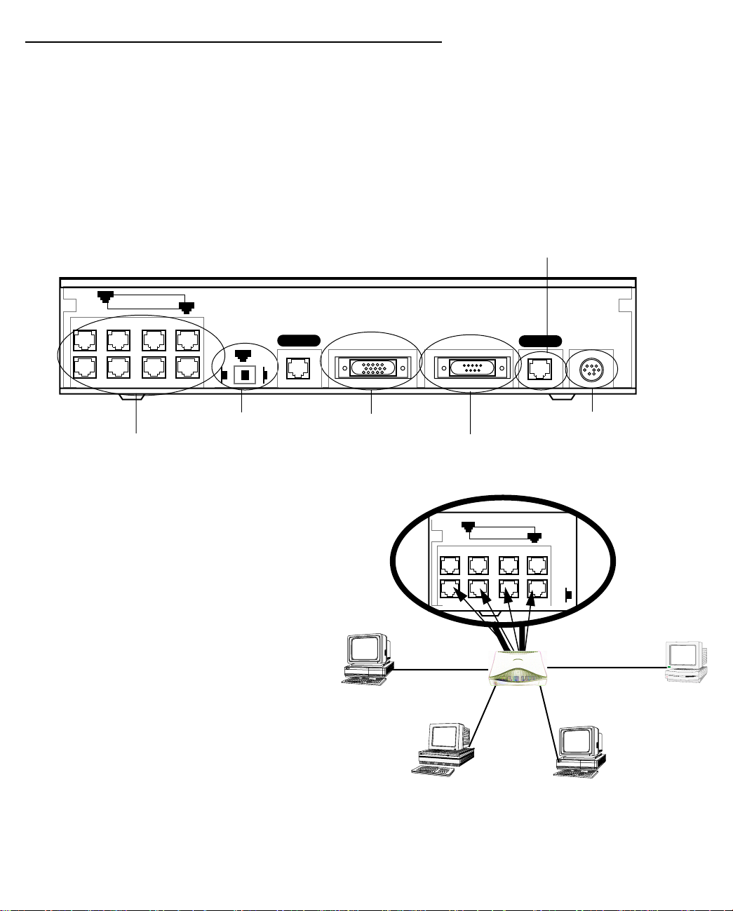
CCCCoooonnnnnnnneeeeccccttttiiiinnnngggg ttttoooo aaaannnn EEEEtttthhhheeeerrrrnnnneeeetttt nnnneeeettttwwwwoooorrrrkk
kk
The Netopia R5000 Series supports Ethernet connections through its eight Ethernet ports. The router
automatically detects which Ethernet port is in use.
You can connect 10Base-T or 10/100 Ethernet devices to the Netopia R5000 Series Router.
11110000BBBBaaaasssseeee----TT
TT
You can connect a standard 10Base-T Ethernet network to the Netopia R5000 Series Router using any of its
available Ethernet ports.
Netopia R5200/5300 back panel
Line port
8
Ethernet
8 port Ethernet hub
1
Normal
1
Uplink
Crossover switch
Line 2
Auxiliary Console Power
Line 1
Auxiliary port
Console port
Power port
The Netopia R5000 Series in a 10Base-T network
T o connect your 10Base-T network to the Netopia
R5000 Series through an Ethernet port, use a
10Base-T cable with RJ-45 connectors.
If you have more than eight devices to connect,
you can attach additional devices using another
10Base-T hub.
8
Ethernet
1
Nor-
Page 30
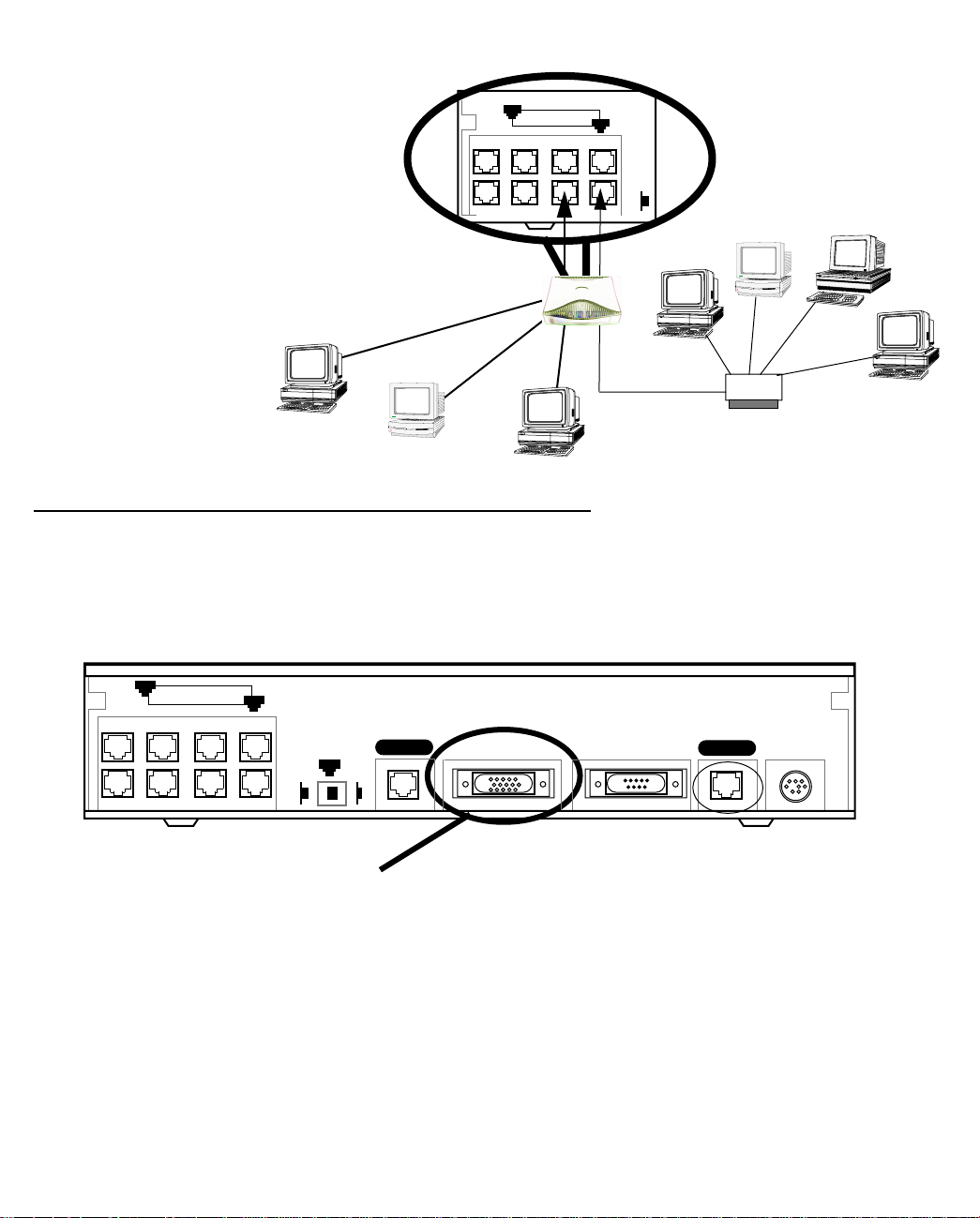
4-4 User’s Reference Guide
If you add devices connected
through a hub, connect the hub to
Ethernet port number 1 on the
Netopia R5000 Series Router and
set the Normal/Uplink switch to
Uplink.
PC
Macintosh
8
Ethernet
PC
1
Nor-
10Base-T
Hub
AAAAddddddddiiiinnnngggg aaaannnn eeeexxxxtttteeeerrrrnnnnaaaallll mmmmooooddddeeeemm
mm
You may want to add an external modem to your Auxiliary port so that you can manage it even if the Internet
connectyion isn’t functioning. Obtain the special DB-25 external modem cable (TE6/DB25) either from your
reseller or directly from Netopia.
Netopia R5000 Series Auxiliary port for connecting an external modem
8
Ethernet
1
Auxiliary Console Power
Line 1
Normal
1
Line 2
Uplink
Auxiliary connection port
HD-15 (female)
By default, the Auxiliary port on your Netopia R5000 Series is enabled for remote console-based management
via an external modem. This means that all you have to do is connect your modem to the Auxiliary port and
configure the router for any AT command string your modem requires in the Line Configuration screens under
the WAN Configuration menu.
For pinout information on the HD-15 to DB-25 modem cable, see “Pinouts for Auxiliary port modem cable,” in
Appendix F, “Technical Specifications and Safety Information.”
Page 31

Connecting to Your Local Area Network 4-5
CCCCoooonnnnnnnneeeeccccttttiiiinnnngggg ttttoooo aaaa LLLLooooccccaaaallllTTTTaaaallllkkkk nnnneeeettttwwwwoooorrrrkkkk
If you have purchased the AppleTalk feature expansion kit, you can also connect the router to an AppleTalk
network that uses either Ethernet or LocalTalk. Refer to the sheet of optional feature set add-ons in your
Netopia R5000 Series documentation folio.
The AppleTalk feature expansion kit includes a special dual RJ-11 PhoneNET connector that attaches to the
Auxiliary port on the Netopia R5000 Series.
Netopia R5000 Series Auxiliary port for connecting to LocalTalk
8
Ethernet
1
Normal
1
Auxiliary Console Power
Uplink
Line
Auxiliary connection port
HD-15 (female)
Connect the male HD-15 end of the PhoneNET connector to the Auxiliary port on your Netopia R5000 Series.
Connect the other end of the cable to your LocalTalk network. You can use only one connection on the Auxiliary
port. You cannot use both the PhoneNET connector and an external modem.
If your LocalTalk network is not based on standard PhoneNET cabling, use a PhoneNET-to-LocalTalk adaptor
cable available from Farallon Communications, Inc. (www.farallon.com). Connect the adaptor cable’s RJ-11
connector to the AppleTalk cable’s PhoneNET connector. Connect the cable’s mini-DIN-3 connector to your
LocalTalk network.
Be sure to observe Farallon’s recommendations governing maximum cable lengths and limits on the number of
nodes on a PhoneNET network. The dual RJ-11 PhoneNET connector allows insertion in the LocalTalk daisy
chain or at the end. If the device is connected at the end of the daisy chain, you must install the accompanying
terminator.
For detailed configuration instructions see “AppleTalk Setup” on page 11-1.
Page 32

4-6 User’s Reference Guide
Page 33

Setting up your Router with the SmartStart Wizard 5-1
CCCChhhhaaaapppptttteeeerrrr 55
SSSSeeeettttttttiiiinnnngggg uuuupppp yyyyoooouuuurrrr RRRRoooouuuutttteeeerrrr wwwwiiiitttthhhh tttthhhheeee SSSSmmmmaaaarrrrttttSSSSttttaaaarrrrtttt WWWWiiiizzzzaaaarrrrdd
Once you’ve connected your router to your computer and your telecommunications line and installed a web
browser, you’re ready to run the Netopia SmartStart™ Wizard. The SmartStart Wizard will help you set up the
router and share the connection. The SmartStart Wizard walks you through a series of questions and, based on
your responses, automatically configures the router for connecting your LAN to the Internet or to your remote
corporate network.
The SmartStart Wizard will:
■ automatically check your Windows 95, 98, or NT PC’s TCP/IP configuration to be sure you can accept a
dynamically assigned IP address, and change it for you if it is not set for dynamic addressing
■ check the physical connection from your computer to your router without your having to enter an IP address
■ assign an IP address to your router
This chapter covers the following topics:
■ “Before running SmartStart” on page 2
■ “Setting up your Router with the SmartStart Wizard” on page 3
■ “Sharing the Connection” on page 6
55
dd
Page 34

5-2 User’s Reference Guide
BBBBeeeeffffoooorrrreeee rrrruuuunnnnnnnniiiinnnngggg SSSSmmmmaaaarrrrttttSSSSttttaaaarrrrtt
Be sure you have connected the cables and power source as described in Step 1 “Connect the Router” guide
contained in your Netopia folio.
Before you launch the SmartStart application, make sure your computer meets the following requirements:
System
software
Connectivity
software
Connectivity
hardware
Browser
software
Notes:
■ The computer running SmartStart must be on the same Ethernet cable segment as the Netopia
R5000 Series Router. Repeaters, such as 10Base-T hubs between your computer and the Netopia
R5000 Series, are acceptable, but devices such as switches, 10/100 bridges, or other routers are
not.
Windows 95, 98, or NT operating system MacOS 7.5 or later
TCP/IP must be installed and properly
configured. See “Configuring TCP/IP on
Windows 95, 98, or NT computers” on
page 5-6
Ethernet card (10Base-T) Either a built-in or third-party Ethernet card
Netscape Communicator™ or Microsoft Internet Explorer, included on the Netopia CD.
Required for web-based registration and web-based monitoring.
tt
PC Macintosh
MacTCP or Open Transport TCP/IP must be
installed and properly configured. See
“Configuring TCP/IP on Macintosh
computers” on page 5-10.
(10Base-T)
■ The Easy setup option in SmartStart for the PC will offer to set your TCP/IP control panel to “Obtain
an IP address automatically” if it is not already set this way. This will cause your computer to reboot.
If you have a specified IP address configured in the computer, you should make a note of it before
running SmartStart, if you do not want to use the dynamic LAN IP addressing features built in to the
Netopia Router. You may choose to use the console cable to connect directly to the console-based
management. Alternatively, you can restore your computer to its fixed IP address after changing the
default LAN IP addressing scheme of the router to match.
Page 35

Setting up your Router with the SmartStart Wizard 5-3
SSSSeeeettttttttiiiinnnngggg uuuupppp yyyyoooouuuurrrr RRRRoooouuuutttteeeerrrr wwwwiiiitttthhhh tttthhhheeee SSSSmmmmaaaarrrrttttSSSSttttaaaarrrrtttt WWWWiiiizzzzaaaarrrrdd
The SmartStart Wizard is tailored for your platform, but it works the same way on either a PC or a Macintosh.
Insert the Netopia CD, and in the desktop navigation screen that appears, launch the SmartStart Wizard
application.
SSSSmmmmaaaarrrrttttSSSSttttaaaarrrrtttt WWWWiiiizzzzaaaarrrrdddd ccccoooonnnnffffiiiigggguuuurrrraaaattttiiiioooonnnn ssssccccrrrreeeeeeeennnnssss
The screens described in this section are the default screens shipped on the Netopia CD. They
derive from two initialization (.ini) files included in the same directory as the SmartStart
application file. Your reseller or your ISP may have supplied you with customized versions of these
files.
■ If you have received a CD or diskette that has been customized by your reseller or ISP, you
can run the SmartStart Wizard directly from the CD or diskette and follow the instructions
your reseller or ISP provides. This makes your Netopia R5000 Series configuration even
easier.
■ If you have received only the .ini files from your reseller or ISP, perform the following:
■ Copy the entire directory folder containing the SmartStart Wizard application from the
Netopia CD to your hard disk.
■ Copy the customized .ini files to the same directory folder that contains the SmartStart
Wizard application, allowing the copy process to overwrite the original .ini files.
dd
■ Run the SmartStart Wizard from your hard disk. You can then follow the instructions your
reseller or ISP provides.
The SmartStart Wizard presents a series of screens to guide you through the preliminary configuration of a
Netopia R5000 Series. It will then create a connection profile using the information you supply to it.
Welcome screen. The first screen welcomes you to the
SmartStart Wizard configuration utility.
Click the Next button after you have responded to the
interactive prompts in each screen.
The Help button will display useful information to assist
you in responding to the interactive prompts.
Page 36

5-4 User’s Reference Guide
Setup options screen. You can choose either Easy or
Advanced setup.
■ If you choose Easy, SmartStart automatically uses
the preconfigured IP addressing setup built into your
router. This is the best choice if you are creating a
new network or don’t already have an IP addressing
scheme on your network.
If you choose Easy, you will see a “Connection Test
screen,” like the one shown below while SmartStart
checks the connection to your router.
■ If you choose Advanced, skip to page 5-5 now. The
SmartStart Wizard displays the “Router IP Address
screen” on page 5-5. Choose this path to modify your
router’s IP address to match an existing IP
addressing scheme.
EEEEaaaassssyyyy ooooppppttttiiiioooonn
nn
Connection Test screen. SmartStart tests the
connection to the router. While it is testing the
connection, a progress indicator screen is displayed and
the router’s Ethernet LEDs flash.
When the test succeeds, SmartStart indicates success.
If the test fails, the wizard displays an error screen. If the test fails, check the following:
■ Check your cable connections. Be sure you have connected the router and the computer properly, using the
correct cables. Refer to the Step 1 “Connect the Router” sheet in your Netopia R5000 Series
documentation folio.
■ Make sure the router is turned on and that there is an Ethernet connection between your computer and the
router.
■ Check the TCP/IP control panel settings to be sure that automatic IP Addressing (Windows) or DHCP
(Macintosh) is selected. If you are using a Windows PC, SmartStart will automatically detect a static IP
address and offer to configure the computer for automatic addressing. On a Macintosh computer, you must
manually set the TCP/IP Control Panel to DHCP. See “Configuring TCP/IP on Macintosh computers” on
page 5-10. If you currently use a static IP address outside the 192.168.1.x network, and want to continue
using it, use the Advanced option to assign the router an IP address in your target IP range. See “Advanced
option” on page 5-5.
■ If all of the above steps fail to resolve the problem, reset the router to its factory default settings and rerun
SmartStart. See “Factory defaults” on page 14-7 for instructions.
Page 37

Setting up your Router with the SmartStart Wizard 5-5
When the test is successful, SmartStart presents you with the “Additional Configuration screen,” shown below.
Additional Configuration screen. If you have a router that
has a permanent unswitched connection to your ISP, such
as a Netopia R5000 Series Router, the Additional
Configuration screen appears.
You may want to do additional configuration to customize
your network environment. SmartStart lets you launch
your Telnet application by clicking the Telnet button.
Advanced configuration options available via Telnet are
explained in “Console-Based Management” on page 6-1.
However, if you need no further configuration options,
click Quit. Congratulations! You’re finished!
AAAAddddvvvvaaaannnncccceeeedddd ooooppppttttiiiioooonn
Router IP Address screen. If you selected the Advanced
option in the “Setup options screen” on page 5-4,
SmartStart asks you to choose between entering the
router’s current IP address and assigning an IP address
to the router.
If the router has already been assigned an IP address,
select the first radio button. If you do this, the “Known IP
Address screen,” appears (shown below.)
If you want to reconfigure the router with a new IP address
and subnet mask, select the second radio button. If you
do this, the “New IP Address screen” on page 5-6
appears.
When you have done this, click Next.
nn
Page 38

5-6 User’s Reference Guide
Known IP Address screen. SmartStart displays a
recommended address for the router based on the IP
address of the computer.
If you know the router has an IP address different from
the default value, enter it now. Otherwise, accept the
recommended address.
When you have done this, click Next.
SmartStart tests the connection to your router.
SmartStart then returns you to an “Additional
Configuration screen” on page 5-5.
New IP Address screen. If you want to change the router’s
IP address, you enter the new IP address, the subnet mask,
and the router’s serial number in this screen. Remember,
the serial number is on the bottom of the router. It is also
found in your documentation folio.
Note: Forcing a new IP address may turn off the Netopia
R5000 Series’s IP address serving capabilities, if you
assign an IP address and subnet mask outside the router’s
current IP address serving pool. The Netopia R5000 Series
does not allow an invalid address to be served. Use this
option with caution.
When you have done this, click Next.
SmartStart forces the new IP address into the router, tests the connection, and then resets the
router.
SmartStart then returns you to the “Additional Configuration screen” on page 5-5.
SSSShhhhaaaarrrriiiinnnngggg tttthhhheeee CCCCoooonnnnnnnneeeeccccttttiiiioooonn
CCCCoooonnnnffffiiiigggguuuurrrriiiinnnngggg TTTTCCCCPPPP////IIIIPPPP oooonnnn WWWWiiiinnnnddddoooowwwwssss 99995555,,,, 99998888,,,, oooorrrr NNNNTTTT ccccoooommmmppppuuuutttteeeerrrrss
Configuring TCP/IP on a Windows computer requires the following:
■ An Ethernet card (also known as a network adapter)
■ The TCP/IP protocol must be “bound” to the adapter or card
nn
ss
Page 39

Setting up your Router with the SmartStart Wizard 5-7
DDDDyyyynnnnaaaammmmiiiicccc ccccoooonnnnffffiiiigggguuuurrrraaaattttiiiioooonnnn ((((rrrreeeeccccoooommmmmmmmeeeennnnddddeeeedddd))
If you configure your Netopia R5000 Series using SmartStart, you can accept the dynamic IP address assigned
by your router. The Dynamic Host Configuration Protocol (DHCP) server, which enables dynamic addressing, is
enabled by default in the router. If your PC is not set for dynamic addressing, SmartStart will offer to do this for
you if you select the Easy setup option. In that case, you will have to restart your PC and relaunch SmartStart.
If you configure your PC for dynamic addressing in advance, SmartStart need only be launched once. To
configure your PC for dynamic addressing do the following:
1. Go to the Start
Menu/Settings/Control
Panels and double click
the Network icon. From
the Network components
list, select the
Configuration tab.
))
2. Select TCP/IP-->Your Network Card. Then select
Properties. In the TCP/IP Properties screen (shown here),
select the IP Address tab. Click “Obtain an IP Address
automatically”.
3. Click on the DNS Configuration tab. Click Disable DNS.
DNS will be assigned by the router with DHCP.
4. Click OK in this window and the next window. When
prompted, reboot the computer.
Note: Y ou can also use these instructions to configure other computers on your network to accept IP addresses
served by the Netopia R5000 Series.
Page 40

5-8 User’s Reference Guide
SSSSttttaaaattttiiiicccc ccccoooonnnnffffiiiigggguuuurrrraaaattttiiiioooonnnn ((((ooooppppttttiiiioooonnnnaaaallll))
If you are manually configuring for a fixed or static IP address, perform the following:
1. Go to Start Menu/Settings/Control Panels and double click the Network icon. From the Network
components list, select the Configuration tab.
2. Select TCP/IP-->Your Network Card. Then select Properties. In the TCP/IP Properties screen (shown
below), select the IP Address tab. Click “Specify an IP Address.”
Enter the following:
IP Address: 192.168.1.2
Subnet Mask: 255.255.255.0, or for 12-user models 255.255.255.240
This address is an example of one that can be used to configure the router with the Easy option in the
SmartStart Wizard. Your ISP or network administrator may ask you to use a different IP address and
subnet mask.
))
Page 41

Setting up your Router with the SmartStart Wizard 5-9
3. Click on the Gateway tab (shown below).
Under “New gateway,” enter
192.168.1.1. Click Add. This is the
Netopia R5000 Series’s pre-assigned IP
address.
4. Click OK in this window and the next window. When prompted, reboot the computer.
Click on the DNS Configuration tab. Click Enable DNS.
Enter the following
information:
Host: Type the name
you want to give to
this computer.
Domain: Type your
domain name. If you
don't have a domain
name, type your ISP's
domain name; for
example,
netopia.com.
DNS Server Search
Order: Type the
primary DNS IP
address given to you
by your ISP. Click
Add. Repeat this process for the secondary DNS.
Domain Suffix Search Order: Enter the same domain
name you entered above.
Note: You can also use these instructions to configure other computers on your network with manual or static
IP addresses. Be sure each computer on your network has its own IP address.
Page 42

5-10 User’s Reference Guide
CCCCoooonnnnffffiiiigggguuuurrrriiiinnnngggg TTTTCCCCPPPP////IIIIPPPP oooonnnn MMMMaaaacccciiiinnnnttttoooosssshhhh ccccoooommmmppppuuuutttteeeerrrrss
The following is a quick guide to configuring TCP/IP for MacOS computers. Configuring TCP/IP in a Macintosh
computer requires the following:
■ You must have either Open Transport or Classic Networking (MacTCP) installed.
Note: If you want to use the Dynamic Host Configuration Protocol (DHCP) server built into your Netopia
R5000 Series to assign IP addresses to your Macintoshes, you must be running Open Transport, standard
in MacOS 8 and optional in earlier system versions. You can have your Netopia R5000 Series dynamically
assign IP addresses using MacTCP; however, to do so requires that the optional AppleTalk kit be installed
which can only be done after the router is configured.
■ You must have built-in Ethernet or a third-party Ethernet card and its associated drivers installed in your
Macintosh.
DDDDyyyynnnnaaaammmmiiiicccc ccccoooonnnnffffiiiigggguuuurrrraaaattttiiiioooonnnn ((((rrrreeeeccccoooommmmmmmmeeeennnnddddeeeedddd))
If you configure your Netopia R5000 Series using SmartStart, you can accept the dynamic IP address assigned
by your router. The Dynamic Host Configuration Protocol (DHCP), which enables dynamic addressing, is enabled
by default in the router. To configure your Macintosh computer for dynamic addressing do the following:
1. Go to the Apple menu. Select Control Panels and then
TCP/IP.
2. With the TCP/IP window open, go to the Edit menu and
select User Mode. Choose Basic and click OK.
))
ss
3. In the TCP/IP window, select “Connect via: Ethernet” and
“Configure: Using DHCP Server.”
Note: Y ou can also use these instructions to configure other computers on your network to accept IP addresses
served by the Netopia R5000 Series.
Page 43

Setting up your Router with the SmartStart Wizard 5-11
SSSSttttaaaattttiiiicccc ccccoooonnnnffffiiiigggguuuurrrraaaattttiiiioooonnnn ((((ooooppppttttiiiioooonnnnaaaallll))
))
If you are manually configuring for a fixed or static IP address,
perform the following:
1. Go to the Apple menu. Select Control Panels and then
TCP/IP or MacTCP.
2. With the TCP/IP window open, go to the Edit menu and
select User Mode. Choose Advanced and click OK.
Or, in the MacTCP window, select Ethernet and click the
More button.
3. In the TCP/IP window or in the MacTCP/More window, select or type information into the fields as shown in
the following table.
Option: Select/Type:
Connect via: Ethernet
Configure: Manually
IP Address: 192.168.1.2
Subnet mask: 255.255.255.0, or for 12-user models
255.255.255.240
Router or Gateway address: 192.168.1.1
Name server address: Enter the primary and secondary name server
addresses given to you by your ISP
Implicit Search Path:
Starting domain name:
Enter your domain name; if you do not have a
domain name, enter the domain name of your ISP
4. Close the TCP/IP or MacTCP control panel and save the settings.
5. If you are using MacTCP, you must restart the computer. If you are using Open Transport, you do not need
to restart.
Note: You can also use these instructions to configure other computers on your network with manual or static
IP addresses. Be sure each computer on your network has its own IP address.
Page 44

5-12 User’s Reference Guide
DDDDyyyynnnnaaaammmmiiiicccc ccccoooonnnnffffiiiigggguuuurrrraaaattttiiiioooonnnn uuuussssiiiinnnngggg MMMMaaaaccccIIIIPPPP ((((ooooppppttttiiiioooonnnnaaaallll))
))
If you want to use MacIP to dynamically assign IP addresses to the Macintosh computers on your network you
must install the optional AppleTalk feature set kit.
Note: Y ou cannot use MacIP dynamic configuration to configure your Netopia R5000 Series Router because you
must first configure the router in order to enable AppleTalk.
Once the AppleTalk kit is installed, you can configure your Macintoshes for MacIP. To configure dynamically
using MacIP, perform the following:
Using Open Transport TCP/IP
1. Go to the Apple menu. Select Control Panels and then TCP/IP.
2. With the TCP/IP window open, go to the Edit menu and select User Mode. Choose Advanced and click OK.
3. In the TCP/IP window, select or type information into the fields as shown in the following table.
TCP/IP Option: Select/ Type:
Connect via: AppleTalk (MacIP)
Configure: Using MacIP server
MacIP Server zone: (select available zone)
Name server address: Enter the primary and secondary name server
addresses given to you by your ISP
Implicit Search Path:
Starting domain name:
Enter your domain name; if you do not have a
domain name, enter the domain name of your ISP
4. Close the TCP/IP control panel and save the settings.
Page 45

Setting up your Router with the SmartStart Wizard 5-13
Using Classic Networking (MacTCP)
1. Go to the Apple Menu. Select Control Panels and then Network.
2. In the Network window, select EtherTalk.
3. Go back to the Apple menu. Select Control Panels and then MacTCP.
4. Select EtherTalk.
From the pull-down menu under EtherTalk, select an available zone; then click the More button.
In the MacTCP/More window select the Server radio button. If necessary, fill in the Domain Name Server
Information given to you by your administrator.
5. Restart the computer.
Note: More information about configuring your Macintosh computer for TCP/IP connectivity through a Netopia
R5000 Series can be found in Technote NIR_026, “Open Transport and Netopia Routers,” located on the
Netopia Web site.
Page 46

5-14 User’s Reference Guide
Page 47

Console-Based Management 6-1
CCCChhhhaaaapppptttteeeerrrr 66
CCCCoooonnnnssssoooolllleeee----BBBBaaaasssseeeedddd MMMMaaaannnnaaaaggggeeeemmmmeeeennnntt
Console-based management is a menu-driven interface for the capabilities built into the Netopia R5000 Series
routers. Console-based management provides access to the full range of features that the router supports. You
can customize these features for your individual setup. This chapter describes how to access the
console-based management screens.
This section covers the following topics:
■ “Connecting through a Telnet session” on page 6-2
■ “Connecting a console cable to your router” on page 6-3
■ “Navigating through the console screens” on page 6-4
Console-based management screens contain seven entry points to the Netopia Router configuration and
monitoring features. The entry points are displayed in the Main Menu shown below:
66
tt
Netopia R5300 v4.3.3
Easy Setup...
WAN Configuration...
System Configuration...
Utilities & Diagnostics...
Statistics & Logs...
Quick Menus...
Quick View...
You always start from this main screen.
■ The Easy Setup menus display and permit changing the values contained in the default connection profile.
Experienced users can use Easy Setup to initially configure the router directly through a console session.
Easy Setup menus contain up to five descendant screens for viewing or altering these values. The number
of screens depends on whether you have optional features installed.
■ The W AN Configuration menu displays and permits changing your connection profile(s) and default profile,
creating or deleting additional connection profiles, and configuring or reconfiguring the manner in which you
Page 48

6-2 User’s Reference Guide
may be using the router to connect to more than one service provider or remote site.
■ The System Configuration menus display and permit changing:
■ Network protocols setup. See “IP Setup and Network Address Translation” on page 9-1, “IPX Setup”
on page 10-1, and “AppleTalk Setup” on page 11-1.
■ Filter sets (firewalls). See “Security” on page 13-1.
■ IP address serving. See “IP address serving” on page 9-22.
■ Date and time. See “Date and time” on page 8-34.
■ Console configuration. See “Connecting a console cable to your router” on page 6-3.
■ SNMP (Simple Network Management Protocol). See “SNMP” on page 12-13.
■ Security. See “Security” on page 13-1.
■ Upgrade feature set. See “Upgrade feature set” on page 8-36.
■ The Utilities & Diagnostics menus provide a selection of seven tools for monitoring and diagnosing the
router's behavior, as well as for updating the firmware and rebooting the system. See “Utilities and
Diagnostics” on page 14-1 for detailed information.
■ The Statistics & Logs menus display nine sets of tables and device logs that show information about your
router, your network, and their history. See “Statistics & Logs” on page 12-4 for detailed information.
■ The Quick Menus screen is a shortcut entry point to 22 of the most commonly used configuration menus
that are accessed through the other menu entry points.
■ The Quick View menu displays at a glance current real-time operating information about your router. See
“Quick View status overview” on page 12-1 for detailed information.
CCCCoooonnnnnnnneeeeccccttttiiiinnnngggg tttthhhhrrrroooouuuugggghhhh aaaa TTTTeeeellllnnnneeeetttt sssseeeessssssssiiiioooonn
nn
Features of the Netopia R5000 Series can be configured through the console screens. If you initially use the
SmartStart Wizard, the application will automatically connect you to the console-based management screens
via Telnet.
Before you can access the console screens through Telnet, you must have:
■ A network connection locally to the router or IP access to the router.
Note: Alternatively, you can have a direct serial console cable connection using the provided console cable
for your platform (PC or Macintosh) and the Console port on the back of the router. For more information on
attaching the console cable, see “Connecting a console cable to your router” on page 6-3.
■ Telnet software installed on the computer you will use to configure the router
Page 49

Console-Based Management 6-3
CCCCoooonnnnffffiiiigggguuuurrrriiiinnnngggg TTTTeeeellllnnnneeeetttt ssssooooffffttttwwwwaaaarrrree
ee
If you are configuring your router using a Telnet session, your computer must be running a Telnet software
program.
■ If you connect a PC with Microsoft Windows, you can use a Windows Telnet application or simply run Telnet
from the Start menu.
■ If you connect a Macintosh computer, you can use the NCSA Telnet program supplied on the Netopia
R5000 Series CD. You install NCSA Telnet by simply dragging the application from the CD to your hard disk.
CCCCoooonnnnnnnneeeeccccttttiiiinnnngggg aaaa ccccoooonnnnssssoooolllleeee ccccaaaabbbblllleeee ttttoooo yyyyoooouuuurrrr rrrroooouuuutttteeeerr
rr
You can perform all of the system configuration activities for your Netopia R5000 Series through a local serial
console connection using terminal emulation software, such as HyperTerminal provided with Windows 95 on the
PC, or ZTerm, included on the Netopia CD, for Macintosh computers.
The Netopia R5000 Series back panel has a connector labeled “Console” for attaching the Router to either a
PC or Macintosh computer via the serial port on the computer. (On a Macintosh computer, the serial port is
called the Modem port or Printer port.) This connection lets you use the computer to configure and monitor the
Netopia R5000 Series via the console screens.
8
Ethernet
1
Normal
1
Auxiliary Console Power
Uplink
Line
Console connection port
DB-9 (male)
T o connect the Netopia R5000 Series to your computer for serial console communication, use the supplied dual
console cable connector end appropriate to your platform:
■ One DB-9 connector end attaches to a PC.
■ The mini-DIN8 connector end attaches to a Macintosh computer.
■ The DB-9 end of the Console cable attaches to the Netopia R5000 Series’s Console port.
■ If you connect a PC with Microsoft Windows 95 or NT, you can use the HyperTerminal application bundled
with the operating system.
■ If you connect a Macintosh computer, you can use the ZTerm terminal emulation program on the supplied
Netopia R5000 Series CD.
Page 50

6-4 User’s Reference Guide
Launch your terminal emulation software and configure the communications software for the values shown in
the table below. These are the default communication parameters that the Netopia R5000 Series uses.
Parameter Suggested Value
Terminal type PC: ANSI-BBS
Mac: ANSI, VT-100, or VT-200
Data bits 8
Parity None
Stop bits 1
Speed 57600 bits per second *
Flow Control None
* Note: The router firmware contains an autobaud detection feature. If you are at any screen on
the serial console, you can change your baud rate and press Return (HyperTerminal for the PC
requires a disconnect). The new baud rate is displayed at the bottom of the screen.
NNNNaaaavvvviiiiggggaaaattttiiiinnnngggg tttthhhhrrrroooouuuugggghhhh tttthhhheeee ccccoooonnnnssssoooolllleeee ssssccccrrrreeeeeeeennnnss
Use your keyboard to navigate the Netopia R5000 Series’s configuration screens, enter and edit information,
and make choices. The following table lists the keys to use to navigate through the console screens.
To... Use These Keys...
Move through selectable items in a screen or pop-up menu Up, Down, Left, and
Set a change to a selected item or open a pop-up menu of
options for a selected item like entering an upgrade key
Change a toggle value (Yes/No, On/Off) Tab
Restore an entry or toggle value to its previous value Esc
Move one item up Up arrow or Control + A
Move one item down Down arrow or Control + Z
Display a dump of the device event log Control + E
Display a dump of the WAN event log Control + F
Refresh the screen Control + L
Go to topmost selectable item <
Go to bottom right selectable item >
ss
Right Arrow
Return or Enter
Page 51

Easy Setup 7-1
CCCChhhhaaaapppptttteeeerrrr 77
EEEEaaaassssyyyy SSSSeeeettttuuuupp
This chapter describes how to use the Easy Setup console screens on your Netopia R5000 Series Router. After
completing the Easy Setup console screens, your router will be ready to connect to the Internet or another
remote site.
EEEEaaaassssyyyy SSSSeeeettttuuuupppp ccccoooonnnnssssoooolllleeee ssssccccrrrreeeeeeeennnnss
Using four Easy Setup console screens, you can:
■ Modify a connection profile for your router for the connection to your ISP or remote location
■ Set up IP addresses and IP address serving
■ Password–protect configuration access to your Netopia R5000 Series Router
AAAAcccccccceeeessssssssiiiinnnngggg tttthhhheeee EEEEaaaassssyyyy SSSSeeeettttuuuupppp ccccoooonnnnssssoooolllleeee ssssccccrrrreeeeeeeennnnss
To access the console screens, Telnet to the Netopia Router over your Ethernet network or physically connect
with a serial console cable and access the Netopia Router with a terminal emulation program. See “Connecting
through a Telnet session” on page 6-2 or “Connecting a console cable to your router” on page 6-3.
Note: Before continuing, make sure you have the information that your telephone service provider, ISP, or
network administrator has given you for configuring the Netopia Router.
77
pp
ss
ss
The Netopia Router’s first console screen, Main Menu, appears in the terminal emulation window of the
attached PC or Macintosh computer when:
■ The Netopia Router is turned on
■ The computer is connected to the Netopia Router
■ Telnet or the terminal emulation software is running and configured correctly
SSSSccccrrrreeeeeeeennnn ddddiiiiffffffffeeeerrrreeeennnncccceeeess
Netopia R5000 Series Router models offering different feature sets will have variations in the fields on certain
screens. Your own Easy Setup screens may look slightly different from those illustrated in this chapter.
ss
Page 52

7-2 User’s Reference Guide
A screen similar to the following Main Menu appears:
Netopia R5300 v4.3.3
Easy Setup...
WAN Configuration...
System Configuration...
Utilities & Diagnostics...
Statistics & Logs...
Quick Menus...
Quick View...
Return/Enter goes to Easy Setup -- minimal configuration.
You always start from this main screen.
If you do not see the Main Menu, verify that:
■ The computer used to view the console screen has its serial port connected to the Netopia R5000 Series’s
Console port or an Ethernet connection to one of its Ethernet ports. See “Connecting a console cable to
your router” on page 6-3 or “Connecting through a Telnet session” on page 6-2.
■ Telnet or the terminal emulation software is configured for the recommended values.
■ If you are connecting via the Console port, your computer’s serial port is not being used by another device,
such as an internal modem, or an application. Turn off all other programs (other than your terminal
emulation program) that may be interfering with your access to the port.
■ You have entered the correct password, if necessary. Your Netopia R5000 Series’s console access may be
password protected from a previous configuration. See your system administrator to obtain the password.
See Appendix A, “Troubleshooting,” for more suggestions.
Select the first item on the Main Menu list, Easy Setup. Press Return to bring up the Line Configuration menu
screen.
■ The Serial Line Configuration screen is described on page 7-3.
■ The T1 Line Configuration screen is described on page 7-4.
■ The DDS Line Configuration screen is described on page 7-5.
Page 53

Easy Setup 7-3
TTTThhhheeee SSSSeeeerrrriiiiaaaallll LLLLiiiinnnneeee EEEEaaaassssyyyy SSSSeeeettttuuuupppp ccccoooonnnnffffiiiigggguuuurrrraaaattttiiiioooonnnn ssssccccrrrreeeeeeeenn
The Serial Line Easy Setup screen appears.
Serial Line Easy Setup
Circuit Type... Permanent Sync
Data Rate (kbps)... Auto
Data Link Encapsulation... Frame Relay
TO MAIN MENU NEXT SCREEN
Enter Information supplied to you by your telephone company.
1. Select Circuit Type and press Return. From the pop-up menu, select your circuit type: Permanent Sync (the
default) or Switched Async.
nn
If you selected Permanent Sync (the default) proceed to Step 2.
If you selected Switched Async, the Data Rate defaults to 57.6 for a high speed modem. You can select
other speeds, from 19.2 to 230.4 from the pop-up menu. Two additional fields are displayed: Modem
Initialization String and Modem Dialing Prefix allow you to set modem parameters.
2. Select Data Rate (kbps) and press Return. From the pop-up menu, select a fixed data rate for your digital
line or select Auto. The Auto setting allows your Netopia Router to determine the data rate of your serial
line at the time of circuit activation. Press Return.
3. Select Data Link Encapsulation and highlight the method of encapsulation that you want to use from the
pop-up menu. The choices offered are PPP , HDLC, and Frame Relay. The default setting is Frame Relay . For
an asynchronous modem, the only encapsulation is PPP. Press Return.
4. Select NEXT SCREEN and press Return. The Easy Setup Profile screen appears. See page 7-6.
Page 54

7-4 User’s Reference Guide
TTTThhhheeee TTTT1111 LLLLiiiinnnneeee ccccoooonnnnffffiiiigggguuuurrrraaaattttiiiioooonnnn ssssccccrrrreeeeeeeenn
nn
The T1 Line Configuration screen appears.
T1 Line Configuration
Line Encoding... B8ZS
Framing Mode... ESF
Number of DS0 Channels: 1
First DS0 Channel: 1
Channel Data Rate... Nx64k
Data Link Encapsulation... Frame Relay
TO MAIN MENU NEXT SCREEN
Enter Information supplied to you by your telephone company.
1. Select Line Encoding and press Return. From the pop-up menu, highlight the encoding your telephone service provider uses: B8Zs or AMI. The default setting is B8Zs. Press Return.
2. Select Framing Mode and press Return. From the pop-up menu, highlight either ESF or D4, depending on
the framing mode that your telephone service provider advises you to use. The default setting is ESF. Press
Return.
3. Select Number of DS0 Channels and enter the number of DS0 channels that you and your telephone
service provider have determined are necessary for your T1 line. The default setting for DS0 Channels is 1
(one). Press Return.
Note: Each DS0 channel represents a 56k or 64k increment in bandwidth. Selecting a number less than
the maximum specifies a fractional-T1 interface. You can have a maximum of 24 DS0 channels.
4. Select First DS0 Channel and enter the number of the first active DS0 channel you will be using. The
default setting is 1 (one). Press Return.
Note: You can change the First DS0 Channel number, which has a valid range from one to the maximum
number minus the number of active channels. If the number of active DS0 channels is 24 (maximum), First
DS0 Channel is hidden.
If you specify a number of DS0 channels less than the maximum, a Contiguous Channels item appears. For
fractional-T1, you can specify whether the DS0 channels are contiguous or alternating by toggling
Contiguous Channels to Yes or No.
5. Select Channel Data Rate and highlight the data rate that your service provider has designated your
channel to connect at. The channel data rate choices are Nx56k or Nx64k. The default is Nx64k. Press
Return.
Page 55

Easy Setup 7-5
6. Select Data Link Encapsulation and highlight the method of encapsulation that you want to use from the
pop-up menu. The choices offered are PPP, HDLC, and Frame Relay. The default setting is Frame Relay.
Press Return.
7. Select NEXT SCREEN and press Return. The Easy Setup Profile screen appears. See page 7-6.
TTTThhhheeee DDDDDDDDSSSS LLLLiiiinnnneeee ccccoooonnnnffffiiiigggguuuurrrraaaattttiiiioooonnnn ssssccccrrrreeeeeeeenn
The DDS Line Configuration screen appears.
DDS Line Configuration
Data Rate (kbps)... Automatic
Data Link Encapsulation... PPP
TO MAIN MENU NEXT SCREEN
Enter Information supplied to you by your telephone company.
1. Select Data Rate and press Return. From the pop-up menu, highlight the data rate that you want your
DDS/ADN line connection to transmit at. The data rate choices are Automatic (the default), 56 kbps, and
64 kbps. Press Return.
nn
Note: As noted above, DDS/ADN Netopia Routers may run 56 kbps or 64 kbps data rates on permanent
circuits. If you accept the default, Automatic, the router will hunt between modes until it can determine
what the telephone company has provisioned your DDS/ADN line for.
2. Select Data Link Encapsulation and highlight the method of encapsulation that you want to use from the
pop-up menu. The choices offered are PPP, HDLC, and Frame Relay. The default setting is PPP. Press
Return.
3. Select NEXT SCREEN and press Return. The Easy Setup Profile screen appears. See page 7-6.
Page 56

7-6 User’s Reference Guide
EEEEaaaassssyyyy SSSSeeeettttuuuupppp PPPPrrrrooooffffiiiilllleeee ssssccccrrrreeeeeeeenn
nn
The Easy Setup Profile screen appears.
Connection Profile 1: Easy Setup Profile
Connection Profile Name: Easy Setup Profile
Address Translation Enabled: Yes
IP Addressing... Unnumbered
Remote IP Address: 127.0.0.2
Remote IP Mask: 255.255.255.255
Frame Relay Management Type... ANSI (Annex D)
PREVIOUS SCREEN NEXT SCREEN
Enter basic information about your WAN connection with this screen.
The Easy Setup Profile screen is where you configure the parameters that control the Netopia R5000 Series
Router’s connection to a specific remote destination, usually your ISP or a corporate site.
On a Netopia R5000 Series Router you can add up to 15 more connection profiles, for a total of 16, although
you can only use one at a time.
1. To enable address translation, toggle Address Translation Enabled to Yes (the default). For more
information on Network Address Translation, see Chapter 9, “IP Setup and Network Address Translation,”
on page 9-1.
2. You can toggle IP Addressing to either Unnumbered (the default) or Numbered.
3. Select the Local WAN IP Address field. The default address is 0.0.0.0, which allows for dynamic
addressing, when your ISP assigns an address each time you connect. However, you may enter another
specific address if you want to use static addressing. In that case, enter the local WAN address your ISP
gave you.
When using numbered interfaces, the Netopia Router will use its local WAN IP address and subnet mask to
send packets to the remote router. Both routers have WAN IP addresses and subnet masks associated
with the connection.
When using unnumbered interfaces, the Netopia Router will use either its local Ethernet IP address or its
NAT address (if so configured) and subnet mask to send packets to the remote router. Neither router has a
WAN IP address or subnet mask associated with this connection.
4. If you chose Frame Relay as your datalink encapsulation method, select Frame Relay Management Type
and from the pop-up menu choose ANSI (Annex D), CCITT (Annex A), LMI, or None. ANSI (Annex D) is the
default.
Page 57

Easy Setup 7-7
If you chose PPP as your datalink encapsulation method, select PPP Authentication and from the pop-up
menu choose: None (the default), PAP, CHAP, PAP-TOKEN, or CACHE-TOKEN. Selecting any authentication
method other than the default None will display fields for you to enter your authentication information, such
as User Name and Password.
5. Select NEXT SCREEN and press Return. The IP Easy Setup screen appears.
Note: For more Easy Setup options, see the next section. For more Frame Relay configuration options see
“Configuring Frame Relay” on page 8-6.
IIIIPPPP EEEEaaaassssyyyy SSSSeeeettttuuuupp
pp
The IP Easy Setup screen is where you enter information about your Netopia Router’s:
■ Ethernet IP address
■ Ethernet Subnet mask
■ Domain Name
■ Domain Name Server IP address
■ Default gateway IP address
Consult with your network administrator to obtain the information you will need. For more information about
setting up IP, see “IP Setup and Network Address Translation” on page 9-1.
IP Easy Setup
Ethernet IP Address: 192.168.1.1
Ethernet Subnet Mask: 255.255.255.0
Domain Name:
Primary Domain Name Server: 0.0.0.0
Default IP Gateway: 0.0.0.0
IP Address Serving: On
Number of Client IP Addresses: 100
1st Client Address: 192.168.1.100
PREVIOUS SCREEN NEXT SCREEN
Enter an IP address in decimal and dot form (xxx.xxx.xxx.xxx).
Set up the basic IP & IPX attributes of your Netopia in this screen.
1. Select Ethernet IP Address and enter the first IP address from the IP address range your ISP has given
you. This will be the Netopia Router’s IP address.
If Network Address Translation is enabled in the Easy Setup connection profile, the Ethernet IP Address
defaults to an address within a range reserved by the Internet address administration authority for use
within private networks, 192.168.1.1.
Page 58

7-8 User’s Reference Guide
Because this is a private network address, it should never be directly connected to the Internet. Using NAT
for all your connection profiles will ensure this restriction. See “IP Setup and Network Address Translation”
on page 9-1 of this guide for more information.
2. Select Ethernet Subnet Mask and enter the subnet mask your ISP has given you. The Ethernet Subnet
Mask defaults to a standard class mask derived from the class of the Ethernet IP address you entered in
the previous step.
3. Select Domain Name and enter the domain name your ISP has given you.
4. Select Primary Domain Name Server and enter the IP address your ISP has given you. An alternate or
Secondary Domain Name Server field will appear, where you can enter a secondary DNS IP address if your
ISP has given you one.
5. If you do not enter a Default IP Gateway value, the router defaults to the remote IP address you entered in
the Easy Setup connection profile. If the Netopia Router does not recognize the destination of any IP traffic,
it forwards that traffic to this gateway.
Do not confuse the remote IP address and the Default IP Gateway’s address with the block of local IP
addresses you receive from your ISP. You use the local IP addresses for the Netopia R5000 Series’s
Ethernet port and for IP clients on your local network. The remote IP address and the default gateway’s IP
address should point to your ISP’s router.
EEEEaaaassssyyyy SSSSeeeettttuuuupppp SSSSeeeeccccuuuurrrriiiittttyyyy CCCCoooonnnnffffiiiigggguuuurrrraaaattttiiiioooonn
nn
The Easy Setup Security Configuration screen lets you password-protect your Netopia R5000 Series. Input your
Write Access Name and Write Access Password with names or numbers totaling up to eleven digits.
If you password protect the console screens, you will be prompted to enter the name and password you have
specified every time you log in to the console screens. Do not forget your name and password. If you do, you
will be unable to access any of the configuration screens.
Easy Setup Security Configuration
It is strongly suggested that you password-protect configuration access to your
Netopia. By entering a Name and Password pair here, access via serial,
Telnet, SNMP and Web Server will be password-protected.
Be sure to remember what you have typed here, because you will be prompted for
it each time you configure this Netopia.
You can remove an existing Name and Password by clearing both fields below.
Write Access Name:
Write Access Password:
PREVIOUS SCREEN TO MAIN MENU RESTART DEVICE
Configure a Configuration Access Name and Password here.
Page 59

Easy Setup 7-9
The final step in configuring the Easy Setup console screens is to restart the Netopia R5000 Series, so that the
configuration settings take effect.
1. Select RESTART DEVICE. A prompt asks you to confirm your choice.
2. Select CONTINUE to restart the Netopia Router and have your selections take effect.
Additional security features are available. See “Security” on page 13-1.
Note: You can also restart the system at any time by using the Restart System utility (see “Restarting the
system” on page 14-13) or by turning the Netopia Router off and on with the power switch.
Easy Setup is now complete.
Page 60

7-10 User’s Reference Guide
Page 61

PPPPaaaarrrrtttt IIIIIIII:::: AAAAddddvvvvaaaannnncccceeeedddd CCCCoooonnnnffffiiiigggguuuurrrraaaattttiiiioooonn
nn
Page 62

User’s Reference Guide
Page 63

WAN and System Configuration 8-1
CCCChhhhaaaapppptttteeeerrrr 88
WWWWAAAANNNN aaaannnndddd SSSSyyyysssstttteeeemmmm CCCCoooonnnnffffiiiigggguuuurrrraaaattttiiiioooonn
This chapter describes how to use the console-based management screens to access and configure advanced
features of your Netopia R5000 Series Router. You can customize these features for your individual setup.
These menus provide a powerful method for experienced users to set up their router’s connection profiles and
system configuration.
This section covers the following topics:
■ “WAN configuration” on page 8-1
■ “Configuring Frame Relay” on page 8-6
■ “Creating a new Connection Profile” on page 8-14
■ “The default profile” on page 8-20
■ “Scheduled connections (switched async only)” on page 8-23
■ “Connection accounting screens (switched async only)” on page 8-29
■ “System configuration screens” on page 8-32
■ “Navigating through the system configuration screens” on page 8-32
■ “System configuration features” on page 8-33
88
nn
WWWWAAAANNNN ccccoooonnnnffffiiiigggguuuurrrraaaattttiiiioooonn
T o configure your Wide Area Network (WAN) connection, navigate to the W AN Configuration screen from the Main
Menu and select WAN Configuration, then Line Configuration.
Main
Menu
The following sections describe the Line Configuration screen in the WAN Setup menu for an R5100 SA/Serial,
R5200 DDS, and R5300 T1 Netopia Router model with PPP, Cisco-HDLC, or Frame Relay data link
encapsulation enabled.
■ The Serial Line Configuration screen appears for R5100 SA/Serial models (with an external CSU/DSU
connection). See page 8-2.
■ The DDS Line Configuration screen appears for R5200 DDS models (with an internal CSU/DSU
connection). See page 8-3.
■ The T1 Line Configuration screen appears for R5300 T1 models (with an internal CSU/DSU connection).
See page 8-4.
nn
Configuration
WAN
WAN
Setup
Line
Configuration
Page 64

8-2 User’s Reference Guide
LLLLiiiinnnneeee ccccoooonnnnffffiiiigggguuuurrrraaaattttiiiioooonnnn ffffoooorrrr aaaa SSSSeeeerrrriiiiaaaallll lllliiiinnnnee
The Serial Line Configuration screen is where you enter the configuration parameters for your leased line, in
order for the Netopia Router to communicate with the physical connection.
Serial Line Configuration
Circuit Type... Permanent Sync
Data Rate (kbps)... Auto
Invert Tx Clock: No
Circuit Activation Requires... DCD and DSR
Data Link Encapsulation... Frame Relay
Enter Information supplied to you by your telephone company.
1. Select Circuit Type and press Return. From the pop-up menu, select your circuit type: Permanent Sync (the
default) or Switched Async.
ee
2. Select Data Rate (kbps) and press Return. From the pop-up menu, select a fixed data rate for your digital
line or select Auto. (The data rates to choose from range from 56 kbps to the highest synchronized line
speed.) The Auto setting allows your Netopia Router to determine the data rate of your serial line at the
time of circuit activation. For an asynchronous modem, the only encapsulation is PPP. Press Return.
3. Select Invert Tx Clock and toggle to Yes or No depending on whether you use this selection. Press Return.
Invert Tx Clock causes transmitted data to be delayed by half a clock phase. This option is useful for X.21
DTEs (Data Terminal Equipment) because their transmit data can become altered in relation to the clock
sourced by the DCE (Data Communications Equipment).
DTE (Data Terminal Equipment) is a term used to define the equipment rate. It is a designation for the
maximum rate at which a router can exchange information.
DCE (Data Communications Equipment) is a term defined by both Frame Relay and X.25 committees that
applies to switching equipment and is distinguished from the devices that attach to the network (DTE).
4. Select Circuit Activation Requires and from the pop-up menu select DCD-only, DSR-only, or DCD and DSR
(the default). Press Return.
Some V .35 interfaces represent their capability to transfer user data end-to-end with the DCD signal, while
others offer a more accurate representation with DSR. For this latter case, you can choose to ignore DCD
and instead sense DSR as the line status indicator.
Note: This option will be hidden if an X.21 cable is attached.
Page 65

WAN and System Configuration 8-3
5. Select Data Link Encapsulation and highlight the method of encapsulation that you want to use from the
pop-up menu. The choices offered are PPP, HDLC, and Frame Relay. The default setting is Frame Relay.
Press Return.
Note: If you used Easy Setup to configure your router, you have already created a connection profile called
Easy Setup Profile. If you return to the Easy Setup menus and change the Data Link Encapsulation method
you set up in this step, the Easy Setup Data Link Encapsulation method will override this one and change
the default data link encapsulation method in use.
You are now finished configuring the Line Configuration screen. Press the Escape key to return to the WAN
Setup screen.
Note: If you selected Frame Relay as your data link encapsulation method, see “Configuring Frame Relay” on
page 8-6 for more information.
LLLLiiiinnnneeee ccccoooonnnnffffiiiigggguuuurrrraaaattttiiiioooonnnn ffffoooorrrr aaaa DDDDDDDDSSSS lllliiiinnnnee
The DDS Line Configuration screen is where you enter the configuration parameters for your leased line, in order
for the Netopia Router to communicate with the physical connection.
DDS Line Configuration
Data Rate (kbps)... Automatic
Clock Source is: Network
Data Link Encapsulation... PPP
Enter Information supplied to you by your telephone company.
1. Select Data Rate and press Return. From the pop-up menu, highlight the data rate that you want your DDS
line connection to transmit at. The data rate choices are 56 kbps and 64 kbps. The default is Automatic.
Press Return.
ee
Note: DDS Netopia Routers can run 56 kbps or 64 kbps data rates on permanent circuits. You can
alternately select Automatic, in which case the router will hunt between modes until it can determine what
the telephone company has provisioned your DDS line for.
2. The Clock Source default is Network and is not editable.
3. Select Data Link Encapsulation and highlight the method of encapsulation that you want to use from the
pop-up menu. The choices offered are PPP, HDLC, and Frame Relay. The default setting is PPP. Press
Return.
Page 66

8-4 User’s Reference Guide
Note: If you used Easy Setup to configure your router, you have already created a connection profile called
Easy Setup Profile. If you return to the Easy Setup menus and change the Data Link Encapsulation method
you set up in this step, the Easy Setup Data Link Encapsulation method will override this one and change
the default data link encapsulation method in use.
You are now finished configuring the Line Configuration screen. Press the Escape key to return to the WAN
Setup screen.
Note: If you selected Frame Relay as your data link encapsulation method, see “Configuring Frame Relay” on
page 8-6 for more information.
LLLLiiiinnnneeee ccccoooonnnnffffiiiigggguuuurrrraaaattttiiiioooonnnn ffffoooorrrr aaaa TTTT1111 lllliiiinnnnee
ee
The T1 Line Configuration screen is where you enter the configuration parameters for your T1 line, in order for
the Netopia Router to communicate with the physical connection.
T1 Line Configuration
Line Encoding... B8ZS
Framing Mode... ESF
Transmit ANSI PRMs: No
Number of DS0 Channels: 1
First DS0 Channel: 1
Buildout (-dB)... 0-0.6
Channel Data Rate... Nx64k
Clock Source... Network
Data Link Encapsulation... Frame Relay
Enter Information supplied to you by your telephone company.
1. Select Line Encoding and press Return. From the pop-up menu, highlight the encoding your telephone service provider uses: B8ZS or AMI. The default setting is B8ZS. Press Return.
2. Select Framing Mode and press Return. From the pop-up menu, highlight either ESF or D4, depending on
the framing mode that your telephone service provider advises you to use. The default setting is ESF. Press
Return.
3. If you selected ESF framing mode, toggle Transmit ANSI PRMs either No (the default) or Yes. If you
selected D4 framing mode, this option is not available.
4. Select Number of DS0 Channels and enter the number of DS0 channels that you and your telephone
service provider have determined are necessary for your T1 line. The default setting for DS0 Channels is 1
(one). Press Return.
Note: Each DS0 channel represents a 56k or 64k increment in bandwidth. Selecting a number less than
the maximum of 24 specifies a fractional T1 interface.
Page 67

WAN and System Configuration 8-5
For fractional T1, you can also specify in the check box whether the DS0 channels are contiguous or
alternating.
5. Select First DS0 Channel and enter the number of the first active DS0 channel you will be using. The
default setting is 1 (one). Press Return.
Note: You can change the First DS0 Channel number, which has a valid range from one to the maximum
number minus the number of active channels. If the number of active DS0 channels is 24 (maximum), First
DS0 Channel is hidden.
If you specify a number of DS0 channels less than the maximum, a Contiguous Channels item appears. For
fractional-T1, you can specify whether the DS0 channels are contiguous or alternating by toggling
Contiguous Channels to Yes or No.
6. Select Buildout (-dB) and press Return. From the pop-up menu, highlight the line buildout, which is the
transmit attenuation of the line that you will be using. The choices in the menu include Auto, 0-0.6, 7.5,
15.0, 22.5, and None. The default setting is 0-0.6. Press Return.
If Automatic is chosen, the attenuation of the transmission will be set to match the receiving signal level.
7. Select Channel Data Rate and highlight the data rate specified by your service provider. The channel data
rate choices are Nx56k or Nx64k. The default is Nx64k. Press Return.
8. Select Clock Source and press Return. From the pop-up menu, highlight the clock source that you want to
use. The choices offered are Internal Clock Source or Network Clock Source. The default is Network.
Press Return.
9. Select Data Link Encapsulation and highlight the method of encapsulation that you want to use from the
pop-up menu. The choices offered are PPP, HDLC, and Frame Relay. The default setting is Frame Relay.
Press Return.
Note: If you used Easy Setup to configure your router, you have already created a connection profile called
Easy Setup Profile. If you return to the Easy Setup menus and change the Data Link Encapsulation method
you set up in this step, the Easy Setup Data Link Encapsulation method will override this one and change
the default data link encapsulation method in use.
You are now finished configuring the Line Configuration screen. Press the Escape key to return to the WAN
Setup screen.
Note: If you selected Frame Relay as your data link encapsulation method, see “Configuring Frame Relay” on
page 8-6 for more information.
Page 68

8-6 User’s Reference Guide
CCCCoooonnnnffffiiiigggguuuurrrriiiinnnngggg FFFFrrrraaaammmmeeee RRRReeeellllaaaayy
yy
Frame Relay is an alternative data link encapsulation method for use over unswitched connections. If this does
not apply to your connection, you can skip the corresponding sections.
You can specify Frame Relay as your data link encapsulation method in either of two ways:
■ the “Easy Setup Frame Relay screens” on page 8-6 or
■ the “WAN Configuration Frame Relay screens” on page 8-7
EEEEaaaassssyyyy SSSSeeeettttuuuupppp FFFFrrrraaaammmmeeee RRRReeeellllaaaayyyy ssssccccrrrreeeeeeeennnnss
Main
Menu
T1 Line Configuration
Line Encoding... B8ZS
Framing Mode... ESF
ss
Easy
Setup
Line
Configuration
Number of DS0 Channels: 1
First DS0 Channel: 1
Channel Data Rate... +-------------+
+-------------+
| PPP |
Data Link Encapsulation... | HDLC |
| Frame Relay |
TO MAIN MENU +-------------+
Page 69

WAN and System Configuration 8-7
WWWWAAAANNNN CCCCoooonnnnffffiiiigggguuuurrrraaaattttiiiioooonnnn FFFFrrrraaaammmmeeee RRRReeeellllaaaayyyy ssssccccrrrreeeeeeeennnnss
ss
The Line Configuration menu also offers the options of either PPP, HDLC, or Frame Relay as your data link
encapsulation method.
Main
Menu
T1 Line Configuration
Line Encoding... B8ZS
Framing Mode... ESF
Transmit ANSI PRMs: No
Number of DS0 Channels: 1
First DS0 Channel: 1
Buildout (-dB)... Auto
Channel Data Rate... +-------------+
Clock Source... +-------------+
| PPP |
Data Link Encapsulation... | HDLC |
| Frame Relay |
+-------------+
WAN
Configuration
WAN
Setup
Line
Configuration
Page 70

8-8 User’s Reference Guide
FFFFrrrraaaammmmeeee RRRReeeellllaaaayyyy ccccoooonnnnffffiiiigggguuuurrrraaaattttiiiioooonn
nn
If you chose Frame Relay as your data link encapsulation type you can now configure the Frame Relay options
from the WAN Configuration menu.
WAN Configuration
WAN (Wide Area Network) Setup...
Display/Change Connection Profile...
Add Connection Profile...
Delete Connection Profile...
Default Profile...
Frame Relay Configuration...
Frame Relay DLCI Configuration...
Return/Enter for WAN line configuration.
From here you will configure yours and the remote sites' WAN information.
From the WAN Configuration screen, select WAN Setup, then select the Frame Relay Configuration option and
press Return. The Frame Relay Configuration screen appears.
Frame Relay Configuration
LMI Type... ANSI (Annex D)
T391 (Polling Interval in secs): 10
N391 (Polls/Full Status Cycles): 6
N392 (Error Threshold): 3
N393 (Monitored Event Window): 4
Tx Injection Management... Standard
Default CIR: 64000
Default Bc: 64000
Default Be: 0
Congestion Management Enabled: No
Maximum Tx Frame Size: 1520
Return/Enter goes to new screen.
Enter Information supplied to you by your telephone company.
1. Select LMI Type (Link Management Type) and press Return. From the pop-up menu, highlight either ANSI
(Annex D), CCITT (Annex A), LMI, or None. The default is None. Press Return.
Page 71

WAN and System Configuration 8-9
See “Frame Relay DLCI configuration” on page 8-10 for instructions.
Specifying the Link Management Type is the first step in configuring Frame Relay.
■ If you select an LMI Type (Link Management Type) other than None, the T391 option specifies the
number of seconds between the Status Enquiry messages. The default setting is 10.
■ The N391 option specifies the frequency of full status polls, in increments of the basic (T391) polling
cycle. The default setting is 6.
■ The N392 option specifies the maximum number of (link reliability, protocol, and sequence number)
error events that can occur within the N393 sliding window. If an N392 threshold is exceeded, the
switch declares the Netopia Router inactive. The default setting is 3.
■ The N393 option allows the user to specify the width of the sliding N392 monitored event window . The
default setting is 4.
2. Select Tx Injection Management and press Return. From the pop-up menu, highlight Standard if you want
the frames on your line that exceed the configured service parameters to be dropped at the router,
Buffered if you want the frames on your line that exceed the link capacity to be delayed until the link is less
busy, or None if you want all of the frames on your line to be transmitted. Press Return.
Note: If you select None as the Tx Injection Management type, the three Tx Injection Management options
listed below will remain hidden. Go to step 4.
If you select Standard or Buffered as the Tx Injection Management type, then the Default CIR, Bc, and Be
values will appear (in the corresponding fields below the Tx Injection Management field) in order for you to
define the parameters of the management algorithm.
■ The Default CIR (CIR also referred to as Committed Information Rate) represents the average capacity
available to a given PVC (Permanent Virtual Circuit) or DLCI (Data Link Connection Identifier). This setting defaults to 64000, but you may modify the capacity rate if this setting will not be applicable to
you.
■ The Default Bc (Bc also referred to as Committed Burst Size) represents the maximum amount of data
that your Frame Relay service provider agrees to transfer from a given PVC (Permanent Virtual Circuit)
or DLCI (Data Link Connection Identifier). This setting defaults to 64000, but you may change the
capacity rate if necessary.
■ The Default Be (Be also referred to as Excess Burst Size) represents the maximum amount of data
that your Frame Relay service provider will attempt to deliver to a given PVC (Permanent Virtual Circuit)
or DLCI (Data Link Connection Identifier). This setting defaults to 0, but you may change the capacity
rate if necessary.
Note: Some Frame Relay service providers allow for over-subscription of the DLCIs, which occurs when the
total number of CIRs for all PVCs exceeds the line rate setup.
3. Select Congestion Management Enabled and toggle to Yes or No depending on whether you use this
selection. Press Return.
If Congestion Management is enabled, this option causes the Netopia Router to use in-bound FECNs
(Forward Explicit Congestion Notification). This feature is designed to notify you that congestion avoidance
procedures should be initiated where applicable for traffic in the same direction as the received frame. It
indicates that the frame in question has encountered congested resources.
Page 72

8-10 User’s Reference Guide
Note: The Congestion Management Enabled field will only appear if Standard or Buffered is selected as
the option from the Tx Injection Management field.
4. Select Maximum Tx Frame Size and press Return. The default is automatically set to a value suitable for
encapsulating a full Ethernet packet’s transmission load; however you can change the Maximum Frame
Size to suit your network’s transmission load. Press Return.
You are now finished configuring the Frame Relay Configuration screen. Press the Escape key to return to the
WAN Configuration screen. If you need to configure your DLCIs, go to the next section.
FFFFrrrraaaammmmeeee RRRReeeellllaaaayyyy DDDDLLLLCCCCIIII ccccoooonnnnffffiiiigggguuuurrrraaaattttiiiioooonn
If you selected None as your LMI Type then you will need to manually configure your DLCIs.
A Frame Relay DLCI is a set of parameters that tells the Netopia Router how to initially connect to a remote
destination.
The Netopia Router supports up to 16 different Frame Relay DLCI profiles.
Each Frame Relay DLCI configuration you set up allows the Netopia Router to connect your network to another
network that uses IP or IPX over Frame Relay.
To go to the Frame Relay DLCI configuration screen, select Frame Relay DLCI Configuration in the WAN
Configuration screen.
Frame Relay DLCI Configuration
Display/Change DLCIs...
Add DLCI...
Delete DLCI...
nn
Add, delete, and modify DLCIs from here.
DDDDiiiissssppppllllaaaayyyyiiiinnnngggg aaaa FFFFrrrraaaammmmeeee RRRReeeellllaaaayyyy DDDDLLLLCCCCIIII ccccoooonnnnffffiiiigggguuuurrrraaaattttiiiioooonnnn ttttaaaabbbbllllee
To display a view-only table of the Frame Relay DLCIs, select Display/Change DLCIs in the Frame Relay DLCI
Configuration screen, and press Return.
The Frame Relay DLCI Configuration table is a handy way to quickly view the DLCI names and DLCI numbers that
you attribute to your Frame Relay profiles.
ee
Page 73

WAN and System Configuration 8-11
Frame Relay DLCI Configuration
+-DLCI Name----------DLCI Number-+
+--------------------------------+
| |
| DLCI 16 16 |
| |
| |
| |
| |
| |
| |
| |
| |
| |
| |
| |
| |
| |
| |
+--------------------------------+
Up/Down Arrow Keys to select, ESC to dismiss, Return/Enter to Edit.
CCCChhhhaaaannnnggggiiiinnnngggg aaaa FFFFrrrraaaammmmeeee RRRReeeellllaaaayyyy DDDDLLLLCCCCIIII ccccoooonnnnffffiiiigggguuuurrrraaaattttiiiioooonn
nn
To modify a Frame Relay DLCI configuration, select Display/Change DLCIs in the Frame Relay DLCI
Configuration screen.
Select a DLCI Name from the table and press Return to go to the Change DLCI screen. The parameters in this
screen are the same as the parameters in the Add DLCI screen. To find out how to set them, see “Adding a
Frame Relay DLCI configuration” on page 8-12.
Change DLCI
DLCI Name: DLCI 33
DLCI Enabled: Yes
DLCI Number (16-991): 32
Remote IP Address: 2.0.0.2
Page 74

8-12 User’s Reference Guide
AAAAddddddddiiiinnnngggg aaaa FFFFrrrraaaammmmeeee RRRReeeellllaaaayyyy DDDDLLLLCCCCIIII ccccoooonnnnffffiiiigggguuuurrrraaaattttiiiioooonn
nn
To add a new Frame Relay DLCI, select Add DLCI in the Frame Relay DLCI Configuration screen and press
Return. The Add DLCI screen appears.
Add DLCI
DLCI Name: DLCI 16
DLCI Enabled: Yes
DLCI Number (16-991): 16
Remote IP Address: 0.0.0.0
Data Flow Parameters---------------Use Default---------Value----
CIR: Yes
Bc: Yes
Be: Yes
ADD DLCI NOW CANCEL
Return accepts * ESC cancels * Left/Right moves insertion point * Del deletes.
Here you configure the parameters for a single DLCI (Data Link Circuit ID).
1. Select DLCI Name and enter a name for this individual Frame Relay DLCI profile. It can be any name you
want. For example: the name of your ISP or remote branch you’re connecting to such as the corporate
headquarters of your company.
Note: The Netopia Router allows Frame Relay DLCIs to be named, so that you can easily reference and
differentiate them. This is accomplished by giving a DLCI Name to a DLCI Number.
2. Select DLCI Enabled and toggle it to Yes to activate the profile. If you disable this profile, the Netopia
Router will automatically disable and block access to a specific remote DLCI.
3. Select DLCI Number (16-991) and enter a number for this individual DLCI. Check with your Frame Relay
provider to find out what numbers are allocated for each of your DLCI profiles. The DLCI number range
should fall within the range of 16-991.
4. Select Remote IP Address and enter the remote IP address your ISP or network administrator gave you
that represents the remote sites IP address for their router. Press Return.
If you selected Standard or Buffered as the Tx Injection Management type in the Frame Relay Configuration
screen go to the next bulleted item below. If you selected None in the Frame Relay Configuration screen go to
step 6.
Below the Remote IP Address field, the following Data Flow Parameters appear:
■ The CIR (Committed Information Rate) represents the average capacity available to a given PVC (Per-
manent Virtual Circuit) or DLCI (Data Link Connection Identifier). The setting defaults to 64000, but
you may modify the capacity rate by toggling the selection in the Use Default field to No. You can then
enter a different capacity rate in the Value field.
■ The Bc (Committed Burst Size) represents the maximum amount of data that your Frame Relay service
Page 75

WAN and System Configuration 8-13
provider agrees to transfer from a given PVC (Permanent Virtual Circuit) or DLCI (Data Link Connection
Identifier). The setting defaults to 64000, but you may modify the committed burst size by toggling the
selection in the Use Default field to No. You can then enter a different committed burst size in the
Value field.
■ The Be (Excess Burst Size) represents the maximum amount of data that your Frame Relay service
provider will attempt to deliver to a given PVC (Permanent Virtual Circuit) or DLCI (Data Link Connection
Identifier). The setting defaults to 0, but you may modify the excess burst size by toggling the selection
in the Use Default field to No. You can then enter a different excess burst size in the Value field.
Note: Some Frame Relay service providers allow for over-subscription of the DLCIs, which occurs when the
total number of CIRs for all PVCs exceeds the line rate setup.
5. Select ADD DLCI NOW to save the current static Frame Relay DLCI profile that you have just entered, and
press Return to go back to the Frame Relay DLCI Configuration screen. Alternately, you can cancel the
Frame Relay DLCI profile you have just created by selecting CANCEL to exit the Add DLCI screen.
DDDDeeeelllleeeettttiiiinnnngggg aaaa FFFFrrrraaaammmmeeee RRRReeeellllaaaayyyy DDDDLLLLCCCCIIII ccccoooonnnnffffiiiigggguuuurrrraaaattttiiiioooonn
nn
To delete a Frame Relay DLCI configuration, select Delete DLCI in the Frame Relay DLCI Configuration screen
and press Return to display the Frame Relay DLCI configuration table.
Frame Relay DLCI Configuration
+-DLCI Name----------DLCI Number-+
+--------------------------------+
| joe 16 |
+------------------------------------------------------------------------+
+------------------------------------------------------------------------+
| |
| Are you sure you want to delete this DLCI? |
| |
| CANCEL CONTINUE |
| |
| |
+------------------------------------------------------------------------+
| |
| |
| |
| |
| |
| |
+--------------------------------+
1. Highlight the Frame Relay DLCI configuration you wish to delete. Press Return.
2. A Frame Relay DLCI Configuration table appears with a prompt asking you if you want to delete the
connection profile you have just highlighted. Select CONTINUE if you wish to delete this DLCI or CANCEL if
you do not.
You are now finished configuring the Frame Relay DLCI Configuration screen.
Page 76

8-14 User’s Reference Guide
Creating a new Connection Profile
Connection Profiles define the telco and networking protocols necessary for the router to make a remote
connection. A Connection Profile is like an address book entry describing how the router is to get to a remote
site, or how to recognize and authenticate a remote user dialing in to the router. For example, to create a new
Connection Profile, you navigate to the WAN Configuration screen from the Main Menu, and select Add
Connection Profile.
Main
Menu
The Add Connection Profile screen appears.
Add Connection Profile
Profile Name: Profile 02
Profile Enabled: Yes
IP Enabled: Yes
IP Profile Parameters...
IPX Enabled: No
Data Link Encapsulation... PPP
Data Link Options...
Telco Options...
ADD PROFILE NOW CANCEL
Return accepts * ESC cancels * Left/Right moves insertion point * Del deletes.
Configure a new Conn. Profile. Finished? ADD or CANCEL to exit.
WAN
Configuration
Add Connection
Profile
On a Netopia R5000 Series Router you can add up to 15 more connection profiles, for a total of 16.
1. Select Profile Name and enter a name for this connection profile. It can be any name you wish. For
example: the name of your ISP.
2. Toggle the Profile Enabled value to Yes or No. The default is Yes.
3. Select IP Profile Parameters and press Return. The IP Profile Parameters screen appears.
Page 77

WAN and System Configuration 8-15
IP Profile Parameters
Address Translation Enabled: Yes
Local WAN IP Address: 0.0.0.0
Remote IP Address: 0.0.0.0
Remote IP Mask: 0.0.0.0
Filter Set...
Remove Filter Set
Receive RIP: Off
Toggle to Yes if this is a single IP address ISP account.
Configure IP requirements for a remote network connection here.
4. Toggle or enter any IP Parameters you require and return to the Add Connection Profile screen by pressing
Escape. For more information, see “IP Setup and Network Address Translation” on page 9-1.
5. If your router is enabled for IPX routing (see “IPX Setup” on page 10-1) and you will be connecting with an
IPX remote network, toggle IPX Enabled to Yes, and press Return. Otherwise, accept the default No. If IPX
routing is not enabled, this menu item does not appear.
If you enable IPX routing, an IPX Profile Parameters menu item becomes available. Select IPX Profile
Parameters and press Return. The IPX Profile Parameters screen appears.
IPX Profile Parameters
Remote IPX Network: 00000000
Path Delay: 10
NetBios Packet Forwarding: Off
Incoming Packet Filter Set... <<NONE>>
Outgoing Packet Filter Set... <<NONE>>
Incoming SAP Filter Set... <<NONE>>
Outgoing SAP Filter Set... <<NONE>>
Periodic RIP Timer: 60
Periodic SAP Timer: 60
Configure IPX requirements for a remote network connection here.
Page 78

8-16 User’s Reference Guide
6. T oggle or enter any IPX Parameters you require and return to the Add Connection Profile screen by pressing
Escape. For more information, see “IPX Setup” on page 10-1.
7. Select Datalink Options and press Return.
The Datalink Options screen appears. The Datalink Options screen will vary depending on the data link
encapsulation method you are using.
The Frame Relay options screen appears as follows:
Datalink (Frame Relay) Options
Auto-Detect DLCIs: Yes
Multicast DLCI Number: 0
Configure Frame Relay-specific parameters of your Connection Profile here.
You can toggle Auto-Detect DLCIs to Yes (the default) or No for this profile.
You can enter the DLCI Number you want to multicast, if any.
Page 79

WAN and System Configuration 8-17
The PPP options screen for a switched interface appears as follows:
Datalink (PPP/MP) Options
Data Compression... Standard LZS
Send Authentication... PAP
Send User Name:
Send Password:
Receive User Name:
Receive Password:
Maximum Packet Size: 1500
In this Screen you will configure the PPP/MP specific connection params.
You can accept the defaults, or change them if you wish. Y ou can also specify user name and password for
both outgoing and incoming calls. the Send User Name/Password parameters are used to specify your
identity when dialing out to a remote location. The Receive User Name/Password parameters are used
when receiving dial-in clients such as via RAS configuration.
Return to the Add Connection Profile screen by pressing Escape.
Page 80

8-18 User’s Reference Guide
8. For a switched connection only, select Telco Options and press return. the Telco Options screen appears.
Note: For IDSL routers, which do not initiate dial-up connections, this option does not appear.
Telco Options
Dial... Dial In/Out
Number to Dial:
Alternate Site to Dial:
Dial on Demand: Yes
Idle Timeout (seconds): 300
Callback: No
In this Screen you configure options for the ways you will establish a link.
Select Dial and press Return. A pop-up menu appears. You can select the dialing options for this
Connection Profile as Dial In Only, Dial Out Only, or Dial In/Out.
You can:
■ add the number to dial for this Connection Profile
■ add an alternate number
■ change any of the default parameter settings
When you are finished with these entries, press Escape to return to the Add Connection Profile screen.
9. Select ADD PROFILE NOW and press Return. Your new Connection Profile will be added.
Page 81

WAN and System Configuration 8-19
If you want to view the Connection Profiles in your router, return to the WAN Configuration screen, and
select Display/Change Connection Profile. The list of Connection Profiles is displayed in a scrolling pop-up
screen.
WAN Configuration
+-Profile Name---------------------IP Address----IPX Network-+
+------------------------------------------------------------+
| Easy Setup Profile 127.0.0.2 |
| Profile 02 0.0.0.0 |
| |
| |
| |
| |
| |
| |
| |
| |
| |
| |
| |
| |
| |
| |
+------------------------------------------------------------+
Up/Down Arrow Keys to select, ESC to dismiss, Return/Enter to Edit.
If you create a Connection Profile using a particular datalink encapsulation method, that profile will take
precedence whenever you connect to a line that uses that datalink encapsulation. If there is no Connection
Profile with the datalink encapsulation method that the line uses, the router will default to using the Default
Profile. See “The default profile,” for more information.
Page 82

8-20 User’s Reference Guide
TTTThhhheeee ddddeeeeffffaaaauuuulllltttt pppprrrrooooffffiiiillllee
ee
For R5100 SA and R5300 T1 models the Default Profile screen controls whether or not the communication link
will come up without an explicitly configured connection profile. If you have an R5200 DDS model, you can skip
this section. See “Connection Profiles” on page 9-8 for more information. You access the Default Profile screen
from the Main Menu by selecting WAN Configuration and then selecting Default Profile.
Main
Menu
WAN
Configuration
Default
Profile
The Default Profile screen appears.
Default Profile
Must Match a Defined Profile: No
IP Enabled: Yes
IP Parameters...
IPX Enabled: Yes
IPX Parameters...
Configure Default WAN Connection Parameters here.
■ You can set Must Match a Defined Profile item to Yes or No (the default). This item controls whether or
not the communication link will come up without an explicitly configured connection profile. If your ISP is
serving you a dynamic IP Address, you need not explicitly configure a connection profile, and the default
behavior of the router will be to connect automatically once it is powered on.
If Must Match a Defined Profile is set to No, then an IP Enabled item is visible. Toggling this item to Yes
(the default) or No controls whether or not IP will be supported on the communication link. If IP Enabled is
set to Yes, an IP Parameters item becomes visible. If you select IP Parameters the IP Parameters screen
appears (see “IP parameters (default profile) screen” on page 8-21). This screen allows you to configure
various IP parameters for connections established without an explicitly configured connection profile.
Page 83

WAN and System Configuration 8-21
If Must Match a Defined Profile is set to No, then an IPX Enabled item is visible. T oggling this item to Yes
or No (the default) controls whether or not IPX will be supported on the communication link. If IPX Enabled
is set to Yes, an IPX Parameters item becomes visible. If you select IPX Parameters, the IPX Parameters
screen appears (see “IPX parameters (default profile) screen” on page 8-22). This screen allows you to
configure various IPX parameters for connections established without an explicitly configured connection
profile.
IIIIPPPP ppppaaaarrrraaaammmmeeeetttteeeerrrrssss ((((ddddeeeeffffaaaauuuulllltttt pppprrrrooooffffiiiilllleeee)))) ssssccccrrrreeeeeeeenn
The IP Parameters (Default Profile) screen allows you to configure various IP parameters for connections
established without an explicitly configured connection profile:
IP Parameters (Default Profile)
Address Translation Enabled: No
Filter Set (Firewall)...
Remove Filter Set
Receive RIP: Both
Transmit RIP: Off
Return/Enter accepts * Tab toggles * ESC cancels.
The Netopia R5000 Series Router always acts as a DHCP client on the communication link when using a
Default Profile. The DHCP server will supply a local IP address and subnet mask. For a communication link,
Network Address Translation (NAT) is enabled by default in the Default Profile. For details on setting up IP
Parameters see “IP Setup and Network Address Translation” on page 9-1.
nn
Page 84

8-22 User’s Reference Guide
IIIIPPPPXXXX ppppaaaarrrraaaammmmeeeetttteeeerrrrssss ((((ddddeeeeffffaaaauuuulllltttt pppprrrrooooffffiiiilllleeee)))) ssssccccrrrreeeeeeeenn
nn
The IPX Parameters (Default Profile) screen allows you to configure various IPX parameters for connections
established without an explicitly configured connection profile:
IPX Parameters (Default Profile)
NetBios Packet Forwarding: Off
Path Delay: 10
Incoming Packet Filter Set... <<NONE>>
Outgoing Packet Filter Set... <<NONE>>
Incoming SAP Filter Set... <<NONE>>
Outgoing SAP Filter Set... <<NONE>>
Periodic RIP Timer: 60
Periodic SAP Timer: 60
For details on setting up IPX Parameters see “IPX Setup” on page 10-1. For details on setting up Filter Sets see
“Security” on page 13-1.
Page 85

WAN and System Configuration 8-23
Scheduled connections ((
To go to the Scheduled Connections screen, select Scheduled Connections in the WAN Configuration screen.
Scheduled Connections
Display/Change Scheduled Connection...
Add Scheduled Connection...
Delete Scheduled Connection...
((sssswwwwiiiittttcccchhhheeeedddd aaaassssyyyynnnncccc oooonnnnllllyyyy))))
Main
Menu
WAN
Configuration
Scheduled
Connections
Navigate from here to add/modify/change/delete Scheduled Connections.
Page 86

8-24 User’s Reference Guide
Viewing scheduled connections
To display a table of view-only scheduled connections, select Display/Change Scheduled Connection in the
Scheduled Connections screen. Each scheduled connection occupies one row of the table.
Scheduled Connections
+-Days----Begin At---HH:MM---When----Conn. Prof. Name----Enabled-----+
+--------------------------------------------------------------------+
| mtWtfss 08:30PM 06:00 weekly Profile 01 No |
| |
| |
| |
| |
| |
+--------------------------------------------------------------------+
The first column in the table shows a one-letter representation of the Days of the week, from Monday (M or m)
to Sunday (S or s). If a letter representing a day is capitalized, the connection will be activated on that day; a
lower-case letter means that the connection will not be activated on that day. If the scheduled connection is
configured for a once-only connection, the word “once” will appear instead of the days of the week.
The other columns show:
■ The time of day that the connection will Begin At
■ The duration of the connection (HH:MM)
■ Whether it’s a recurring Weekly connection or used Once Only
■ Which connection profile (Conn. Prof.) is used to connect
■ Whether the scheduled connection is currently Enabled
The router checks the date and time set in scheduled connections against the system date and time.
Page 87

WAN and System Configuration 8-25
Adding a scheduled connection
To add a new scheduled connection, select Add Scheduled Connection in the Scheduled Connections screen
and press Return. The Add Scheduled Connection screen appears.
Add Scheduled Connection
Scheduled Connection Enable: On
How Often... Weekly
Schedule Type... Forced
Set Weekly Schedule...
Use Connection Profile...
ADD SCHEDULED CONNECTION CANCEL
Scheduled Connections dial remote Networks on a Weekly or Once-Only basis.
Follow these steps to configure the new scheduled connection:
■ To activate the connection, select Scheduled Connection Enable and toggle it to On. You can make the
scheduled connection inactive by toggling Scheduled Connection Enable to Off.
■ Decide how often the connection should take place by selecting How Often and choosing Weekly or Once
Only from the pop-up menu.
■ The Schedule Type allows you to set the exact weekly schedule or once-only schedule.
Options are:
■ Forced Up, meaning that this connection will be maintained whether or not there is a demand call on
the line.
■ Forced Down, meaning that this connection will be torn down or blocked whether or not there is a
demand call on the line.
■ Demand-Allowed, meaning that this schedule will permit a demand call on the line.
■ Demand-Blocked, meaning that this schedule will prevent a demand call on the line.
■ Periodic, meaning that the connection is retried several times during the scheduled time.
■ If How Often is set to Weekly, the item directly below How Often reads Set Weekly Schedule. If How Often
is set to Once Only, the item directly below How Often reads Set Once-Only Schedule.
Page 88

8-26 User’s Reference Guide
Set Weekly Schedule
If you set How Often to Weekly, select Set Weekly Schedule and go to the Set Weekly Schedule screen.
■ Select the days for the scheduled connection to occur and toggle them to Yes.
Set Weekly Schedule
Monday: No
Tuesday: No
Wednesday: No
Thursday: No
Friday: No
Saturday: No
Sunday: No
Scheduled Window Start Time: 11:50
AM or PM: AM
Scheduled Window Duration Per Day: 00:00
■ Select Scheduled Window Start Time and enter the time to initiate the scheduled connection.
■ You must enter the time in the format H:M, where H is a one- or two-digit number representing the hour and
M is a one- or two-digit number representing the minutes. The colon is mandatory. For example, the entry
1:3 (or 1:03) would be accepted as 3 minutes after one o’clock. The entry 7:0 (or 7:00) would be accepted
as seven o’clock, exactly. The entries 44, :5, and 2: would be rejected.
■ Select AM or PM and choose AM or PM from the pop-up menu.
■ Select Scheduled Window Duration Per Day and enter the maximum duration allowed for this scheduled
connection, per call.
You are finished configuring the weekly options. Return to the Add Scheduled Connection screen to
continue.
Page 89

WAN and System Configuration 8-27
Set Once-Only Schedule
If you set How Often to Once Only, select Set Once-Only Schedule and go to the Set Once-Only Schedule
screen.
Set Once-Only Schedule
Place Call on (MM/DD/YY): 05/07/1998
Scheduled Window Start Time: 11:50
AM or PM: AM
Scheduled Window Duration: 00:00
■ Select Place Call On (Date) and enter a date in the format MM/DD/YY or MM/DD/YYYY (month, day,
year).
Note: You must enter the date in the format specified. The slashes are mandatory. For example, the entry
5/7/98 would be accepted as May 7, 1998. The entry 5/7 would be rejected.
■ Select Scheduled Window Start Time and enter the time to initiate the scheduled connection.
Note: You must enter the time in the format H:M, where H is a one- or two-digit number representing the
hour and M is a one- or two-digit number representing the minutes. The colon is mandatory. For example,
the entry 1:3 (or 1:03) would be accepted as 3 minutes after one o’clock. The entry 7:0 (or 7:00) would be
accepted as seven o’clock, exactly. The entries 44, :5, and 2: would be rejected.
■ Select AM or PM and choose AM or PM.
■ Select Scheduled Window Duration and enter the maximum duration allowed for this scheduled
connection. Use the same format restrictions noted above.
You are finished configuring the once-only options. Return to the Add Scheduled Connection screen to continue.
■ In the Add Scheduled Connection screen, select Use Connection Profile and choose from the list of
connection profiles you have already created. A scheduled connection must be associated with a
connection profile to be useful. The connection profile becomes active during the times specified in the
associated scheduled connection, if any exists.
■ Select ADD SCHEDULED CONNECTION to save the current scheduled connection. Select CANCEL to exit
the Add Scheduled Connection screen without saving the new scheduled connection.
Page 90

8-28 User’s Reference Guide
Modifying a scheduled connection
T o modify a scheduled connection, select Change Scheduled Connection in the Scheduled Connections screen
to display a table of scheduled connections.
Select a scheduled connection from the table and go to the Change Scheduled Connection screen. The
parameters in this screen are the same as the ones in the Add Scheduled Connection screen (except that ADD
SCHEDULED CONNECTION and CANCEL do not appear). T o find out how to set them, see “Adding a scheduled
connection” on page 8-25.
Deleting a scheduled connection
To delete a scheduled connection, select Delete Scheduled Connection in the Scheduled Connections screen
to display a table of scheduled connections.
Select a scheduled connection from the table and press the Return key to delete it. To exit the table without
deleting the selected scheduled connection, press the Escape key.
Page 91

WAN and System Configuration 8-29
CCCCoooonnnnnnnneeeeccccttttiiiioooonnnn aaaaccccccccoooouuuunnnnttttiiiinnnngggg ssssccccrrrreeeeeeeennnnssss ((((sssswwwwiiiittttcccchhhheeeedddd aaaassssyyyynnnncccc oooonnnnllllyyyy))
))
For an R5100 Serial router connected to an asynchronous modem, you can enable system-wide and per
connection profile connection accounting and budgeting. You use this feature to track first minutes and
additional minutes per time period for initiated data calls. Connection accounting is available either through the
console-based management screens or through the web-based management screens. See “Web-based
monitoring” on page 12-20 for more information.
You access the console-based management screens from the WAN Configuration menu by selecting Accounting
Configuration and pressing Return.
Main
Menu
WAN
Configuration
Accounting
Configuration
The Accounting Configuration screen appears.
Accounting Configuration
Router Budgets
Enable Router Budget: On
Day for auto-reset of timers: 0
Maximum Aggregate connect time: 0:00
+----------+
Connection Budgets +----------+
Budgets... | Budget 1 |
| Budget 2 |
| Budget 3 |
+----------+
To edit your budgets select Budgets, and from the pop-up menu, select the budget you want to edit.
Page 92

8-30 User’s Reference Guide
The Budget Setup screen appears.
Connection Budget Setup
Name: Budget 1
Use Connection Profile... Easy Setup Profile
Enforced: Off
Override: Off
Units: Minutes
Limit: 300
Time Period... Week
1st Day of Week... Sunday
Choose the Connection Profile this budget is for.
Configuration is similar to the web-based management configuration screens.
■ Selecting Use Connection Profile displays a pop-up list of all of your connection profiles. Choose the
connection profile you want this budget to apply to and press Return.
■ Toggle Enforced to either On or Off to enforce whether the connection is torn down when the budget limit is
reached.
■ Toggle Override to either On or Off. With Override on you can exceed your budget during the current time
period without tearing down active connections. At the end of the current time period this option is
automatically deactivated. If you want to be able to exceed your enforced budget again, you must toggle
this option to On for each new time period.
Toggling Override to On disables call blocking, even if the call is over its limit. The override flag is
automatically reset to be Off at the start of a new period. This is so that you don’t need to set Enforced to
Off to by-pass the limit, and then forget to turn it back on when the new period starts.
■ The Units (Minutes) field is not editable.
■ In the Limit field enter the number of minutes your budget allows.
■ From the Time Period pop-up select either Week or Month, depending on your budgeting requirements.
■ If you set the time period to Week, from the 1st Day of Week pop-up select the day of the week on which
your budget starts.
If you set the time period to Month, from the 1st Day of Month pop-up select the day of the month on which
your budget starts.
Page 93

WAN and System Configuration 8-31
You can monitor your usage against your budget by reviewing the Connection Budget Statistics screen in the
Accounting Statistics. From the Main Menu select Statistics & Logs and then Accounting Statistics and then
Connection Budget Statistics.
Main
Menu
Statistics &
Logs
Accounting
Statistics
The Budget Statistics screen appears.
Budget Statistics (in HHHH:MM)
Budget Name------First Minutes----Additional Minutes-------Cutoff--Expired
Budget 1 0:00 0:00 2:00
Budget 2 0:00 0:00 5:00
Budget 3 0:00 0:00 10:00
You can view statistics for all your budgets at once or one at a time.
Connection
Budget Statistics
■ Budget Name shows the names of your budgets.
■ First Minutes displays the number of first minutes of outbound calls placed during the recording interval.
■ Additional Minutes displays the remaining time of all outbound calls placed during the recording interval.
■ Cutoff displays the number of hours budgeted for this connection profile.
■ Expired displays the amount of time used against the budgeted amount.
To clear the counters and reset the statistics, use the down arrow key to select a budget and press Return. A
pop-up window will ask you to confirm that you want to clear this budget’s statistics. You can cancel if you
change your mind. To return to the Accounting Statistics screen, press Escape.
Note: If you have Connection Budgets configured, changing the date setting (see “Date and time” on page 8-34)
will reset the Connection Budgets under one of the following conditions:
■ If the new date is greater than the old date and the new date falls outside of the current budget window; or
■ If the new date is in the past and the date is not the current date (i.e., yesterday or earlier).
A warning message is displayed in the console window when a budget is reset.
Page 94

8-32 User’s Reference Guide
SSSSyyyysssstttteeeemmmm ccccoooonnnnffffiiiigggguuuurrrraaaattttiiiioooonnnn ssssccccrrrreeeeeeeennnnssss
You can connect to the Netopia R5000 Series Router’s system configuration screens in either of two ways:
■ By using Telnet with the Router’s Ethernet port IP address
■ Through the console port, using a local terminal (see “Connecting a console cable to your router” on
page 6-3)
You can also retrieve the Netopia R5000 Series Router’s configuration information and remotely set its
parameters using the Simple Network Management Protocol (see “SNMP” on page 12-13).
Open a Telnet connection to the router’s IP address; for example, “192.168.1.1.”
The console screen will open to the Main Menu, similar to the screen shown below:
Netopia R5100 v4.3.3
Easy Setup...
WAN Configuration...
System Configuration...
Utilities & Diagnostics...
Statistics & Logs...
Quick Menus...
Quick View...
Return/Enter goes to Easy Setup -- minimal configuration.
You always start from this main screen.
NNNNaaaavvvviiiiggggaaaattttiiiinnnngggg tttthhhhrrrroooouuuugggghhhh tttthhhheeee ssssyyyysssstttteeeemmmm ccccoooonnnnffffiiiigggguuuurrrraaaattttiiiioooonnnn ssssccccrrrreeeeeeeennnnss
To help you find your way to particular screens, some sections in this guide begin with a graphical path guide
similar to the following example:
Main
Menu
This particular path guide shows how to get to the Network Protocols Setup screens. The path guide represents
these steps:
1. Beginning in the Main Menu, select System Configuration and press Return. The System Configuration
screen appears.
System
Configuration
Network Protocols
Setup
ss
IP Setup
Page 95

WAN and System Configuration 8-33
2. Select Network Protocols and press Return. The Network Protocols screen appears.
3. Select IP Setup and press Return. The IP Setup screen appears.
To go back in this sequence of screens, use the Escape key.
SSSSyyyysssstttteeeemmmm ccccoooonnnnffffiiiigggguuuurrrraaaattttiiiioooonnnn ffffeeeeaaaattttuuuurrrreeeess
ss
The Netopia R5000 Series Router’s default settings may be all you need to configure your Netopia R5000
Series Router. Some users, however, require advanced settings or prefer manual control over the default
selections. For these users, the Netopia R5000 Series provides system configuration options.
To help you determine whether you need to use the system configuration options, review the following
requirements. If you have one or more of these needs, use the system configuration options described in later
chapters.
■ System configuration of dynamic IP address distribution through DHCP, MacIP, or BootP
■ Greater network security through the use of filters
■ System configuration of AppleTalk LAN settings
■ System configuration of connections to AppleTalk networks through the Internet or any IP network, using
AURP (AppleTalk “tunneling”)
■ System configuration of connection profiles
To access the system configuration screens, select System Configuration in the Main Menu, then press
Return.
The System Configuration menu screen appears:
System Configuration
Network Protocols Setup...
Filter Sets (Firewalls)...
IP Address Serving...
Date and Time...
Console Configuration...
SNMP (Simple Network Management Protocol)...
Security...
Upgrade Feature Set...
Logging...
Return/Enter to configure Networking Protocols (such as TCP/IP).
Use this screen if you want options beyond Easy Setup.
Page 96

8-34 User’s Reference Guide
NNNNeeeettttwwwwoooorrrrkkkk pppprrrroooottttooooccccoooollllssss sssseeeettttuuuupp
These screens allow you to configure your network’s use of the standard networking protocols:
■ IP: Details are given in “IP Setup and Network Address Translation” on page 9-1.
■ IPX: Details are given in “IPX Setup” on page 10-1.
■ AppleTalk: Details are given in “AppleTalk Setup” on page 11-1.
Note: AppleTalk requires the optional AppleTalk feature expansion kit.
FFFFiiiilllltttteeeerrrr sssseeeettttssss ((((ffffiiiirrrreeeewwwwaaaallllllllssss))
These screens allow you to configure security on your network by means of filter sets and a basic firewall.
■ Details are given in “Security” on page 13-1.
IIIIPPPP aaaaddddddddrrrreeeessssssss sssseeeerrrrvvvviiiinnnngg
These screens allow you to configure IP address serving on your network by means of DHCP, W ANIP, BootP, and
with the optional AppleTalk kit, MacIP.
■ Details are given in “IP address serving” on page 9-22.
DDDDaaaatttteeee aaaannnndddd ttttiiiimmmmee
You can set the system’s date and time in the Set Date and Time screen.
ee
gg
pp
))
Select Date and Time in the System Configuration screen and press Return. The Set Date and Time screen appears.
Set Date and Time
System Date Format: MM/DD/YY
Current Date (MM/DD/YY): 3/16/1999
System Time Format: AM/PM
Current Time: 10:29
AM or PM: AM
Follow these steps to set the system’s date and time:
Page 97

WAN and System Configuration 8-35
1. Select Current Date and enter the date in the appropriate format. Use one- or two-digit numbers for the
month and day, and the last two digits of the current year. The date’s numbers must be separated by
forward slashes (/).
2. Select Current Time and enter the time in the format HH:MM, where HH is the hour (using either the
12-hour or 24-hour clock) and MM is the minutes.
3. Select AM or PM and choose AM or PM.
Note: If you have Connection Budgets configured, changing the date setting will reset the Connection Budgets
under one of the following conditions:
If the new date is greater than the old date and the new date falls outside of the current budget window; or, if
the new date is in the past and the date is not the current date (i.e. yesterday or earlier). A warning message is
displayed in the console window when a budget is reset.
See “Connection Budgets page” on page 12-26 for more information.
CCCCoooonnnnssssoooolllleeee ccccoooonnnnffffiiiigggguuuurrrraaaattttiiiioooonn
You can change the default terminal communications parameters to suit your requirements.
To go to the Console Configuration screen, select Console Configuration in the System Configuration screen.
Console Configuration
Baud Rate... 57600
Hardware Flow Control: No
SET CONFIG NOW CANCEL
Follow these steps to change a parameter’s value:
nn
1. Select the parameter you want to change.
2. Select a new value for the parameter. Return to step 1 if you want to configure another parameter.
3. Select SET CONFIG NOW to save the new parameter settings. Select CANCEL to leave the parameters
unchanged and exit the Console Configuration screen.
Page 98

8-36 User’s Reference Guide
SSSSNNNNMMMMPPPP ((((SSSSiiiimmmmpppplllleeee NNNNeeeettttwwwwoooorrrrkkkk MMMMaaaannnnaaaaggggeeeemmmmeeeennnntttt PPPPrrrroooottttooooccccoooollll))
These screens allow you to monitor and configure your network by means of a standard Simple Network
Management Protocol (SNMP) agent.
■ Details are given in “SNMP” on page 12-13.
SSSSeeeeccccuuuurrrriiiittttyy
These screens allow you to add users and define passwords on your network.
■ Details are given in “Security” on page 13-1.
UUUUppppggggrrrraaaaddddeeee ffffeeeeaaaattttuuuurrrreeee sssseeeett
You can upgrade your Netopia R5000 Series Router by adding new feature sets through the Upgrade Feature
Set utility.
See the release notes that came with your router or feature set upgrade, or visit the Netopia Web site at
www.netopia.com for information on new feature sets, how to obtain them, and how to install them on your
Netopia R5000 Series.
LLLLooooggggggggiiiinnnngg
You can configure a UNIX-compatible syslog client to report a number of subsets of the events entered in the
router’s WAN Event History. See “WAN Event History” on page 12-7. The Syslog client (for the PC only) is
supplied as a .ZIP file on the Netopia CD.
yy
tt
gg
))
Select Logging from the System Configuration menu. The Logging Configuration screen appears.
Logging Configuration
WAN Event Log Options
Log Boot and Errors: Yes
Log Line Specific: Yes
Log Connections: Yes
Log PPP, DHCP, CNA: Yes
Log IP and IPX: Yes
Syslog Parameters
Syslog Enabled: No
Hostname or IP Address:
Facility... Local 0
Return/Enter accepts * Tab toggles * ESC cancels.
Page 99

WAN and System Configuration 8-37
By default, all events are logged in the event history.
■ By toggling each event descriptor to either Yes or No, you can determine which ones are logged and which
are ignored.
■ You can enable or disable the syslog client dynamically. When enabled, it will report any appropriate and
previously unreported events.
■ You can specify the syslog server’s address either in dotted decimal format or as a DNS name up to 63
characters.
■ You can specify the UNIX syslog Facility to use by selecting the Facility pop-up.
IIIInnnnssssttttaaaalllllllliiiinnnngggg tttthhhheeee SSSSyyyysssslllloooogggg cccclllliiiieeeennnntt
tt
The Goodies folder on the Netopia CD contains a Syslog client daemon program that can be configured to
report the WAN events you specified in the Logging Configuration screen.
To install the Syslog client daemon, exit from the graphical Netopia CD program and locate the CD directory
structure through your Windows desktop or through Windows Explorer. Go to the Goodies directory on the CD
and locate the Sds15000.exe program. This is the Syslog daemon installer. Run the Sds15000.exe program
and follow the on screen instructions for enabling the Windows Syslog daemon.
The following screen shows a sample syslog dump of WAN events:
Mar 5 10:14:06 tsnext.netopia.com Link 1 down: PPP PAP failure
Mar 5 10:14:06 tsnext.netopia.com >>Issued Speech Setup Request from our DN: 5108645534
Mar 5 10:14:06 tsnext.netopia.com Requested Disc. from DN: 917143652500
Mar 5 10:14:06 tsnext.netopia.com Received Clear Confirm for our DN: 5108645534
Mar 5 10:14:06 tsnext.netopia.com Link 1 down: Manual disconnect
Mar 5 10:14:06 tsnext.netopia.com >>Issued Speech Setup Request from our DN: 5108645534
Mar 5 10:14:06 tsnext.netopia.com Requested Disc. from DN: 917143652500
Mar 5 10:14:06 tsnext.netopia.com Received Clear Confirm for our DN: 5108645534
Mar 5 10:14:06 tsnext.netopia.com Link 1 down: No answer
Mar 5 10:14:06 tsnext.netopia.com --Device restarted----------------------------------------Mar 5 10:14:06 tsnext.netopia.com >>Received Speech Setup Ind. from DN: (not supplied)
Mar 5 10:14:06 tsnext.netopia.com Requested Connect to our DN: 5108645534
Mar 5 10:14:06 tsnext.netopia.com ASYNC: Modem carrier detected (more) Modem reports: 26400
V34
Mar 5 10:14:06 tsnext.netopia.com >>WAN: 56K Modem 1 activated at 115 Kbps
Mar 5 10:14:06 tsnext.netopia.com Connect Confirmed to our DN: 5108645534
Mar 5 10:14:06 tsnext.netopia.com PPP: Channel 1 up, Answer Profile name: Default Profile
Mar 5 10:14:06 tsnext.netopia.com PPP: NCP up, session 1, Channel 1 Final (fallback)
negotiated auth: Local PAP , Remote NONE
Mar 5 10:14:06 tsnext.netopia.com PPP: PAP we accepted remote, Channel 1 Remote name: guest
Mar 5 10:14:06 tsnext.netopia.com PPP: MP negotiated, session 1 Remote EDO: 06 03
0000C5700624 0
Mar 5 10:14:06 tsnext.netopia.com PPP: CCP negotiated, session 1, type: Ascend LZS Local
mode: 1, Remote mode: 1
Mar 5 10:14:06 tsnext.netopia.com PPP: BACP negotiated, session 1 Local MN: FFFFFFFF, Remote
MN: 00000001
Mar 5 10:14:06 tsnext.netopia.com PPP: IPCP negotiated, session 1, rem: 192.168.10.100 local:
192.168.1.1
Mar 5 10:14:06 tsnext.netopia.com >>WAN: 56K Modem 1 deactivated
Mar 5 10:14:06 tsnext.netopia.com Received Clear Ind. from DN: 5108645534, Cause: 0
Mar 5 10:14:06 tsnext.netopia.com Issued Clear Response to DN: 5108645534
Mar 5 10:14:06 tsnext.netopia.com Link 1 down: Remote clearing
Mar 5 10:14:06 tsnext.netopia.com PPP: IPCP down, session 1
Mar 5 10:14:06 tsnext.netopia.com >>Received Speech Setup Ind. from DN: (not supplied)
Page 100

8-38 User’s Reference Guide
 Loading...