

Page 1

Netopia™ R3100 ISDN Routers
User’s Reference Guide
Page 2

Copyright
Copyright 1997 - 98, Netopia, Inc. v.0300
All rights reserved. Printed in the U.S.A.
This manual and any associated artwork, software and product designs are copyrighted with
all rights reserved. Under the copyright laws such materials may not be copied, in whole or
part, without the prior written consent of Netopia, Inc. Under the law, copying includes
translation to another language or format.
Netopia, Inc.
2470 Mariner Square Loop
Alameda, CA 94501-1010
U.S.A.
Part Number
For additional copies of this electronic manual, order Netopia part number 6120343-PF-04
Printed copies
For printed copies of this manual, order Netopia part number TER3100/Doc
(P/N 6120343-00-04)
Page 3

CCCCoooonnnntttteeeennnnttttss
ss
Welcome to the Netopia R3100
source for information about your Netopia R3100 ISDN Router. It is intended to be viewed on-line,
using the powerful features of the Adobe Acrobat Reader. The information display has been
deliberately designed to present the maximum information in the minimum space on your screen.
You can keep this document open while you perform any of the procedures described, and find
useful information about the procedure you are performing.
This Table of Contents page you are viewing consists of hypertext links to the chapters and
headings listed. If you are viewing this on-line, just click any link below to go to that heading.
User’s Reference Guide
Configuration options for your Netopia R3100 ISDN Router............1
1. Small Office connection to the Internet........................... 2
2. Small Office connection to the Internet........................... 3
3. Direct Connection to a Corporate Office (Telecommuter) .. 4
4. Configured to accept incoming dial-up connections.......... 5
5. Configured for IDSL....................................................... 6
. This guide is designed to be your single
Part I: Getting Started
Chapter 1 — Introduction..........................................................1-1
Overview....................................................................... 1-1
Features and capabilities ............................................... 1-1
How to use this guide .................................................... 1-2
G
B
Chapter 2 — Making the Physical Connections..........................2-1
Find a location............................................................... 2-1
What you need .............................................................. 2-1
Identify the connectors and attach the cables.................. 2-2
Netopia R3100 ISDN Router Back Panel Ports................. 2-3
Netopia R3100 ISDN Router Status Lights....................... 2-6
Chapter 3 — Setting up your Router with the SmartStart Wizard 3-1
Before running SmartStart ............................................. 3-2
Setting up your Router with the SmartStart Wizard........... 3-3
SmartStart Wizard configuration screens ............... 3-3
Easy option.......................................................... 3-4
Advanced option .................................................. 3-9
Sharing the Connection................................................ 3-10
Page 4

ii User’s Reference Guide
Configuring TCP/IP on Windows 95, 98, or NT
computers......................................................... 3-10
Configuring TCP/IP on Macintosh computers........ 3-14
Chapter 4 — Connecting Your Local Area Network.....................4-1
Overview....................................................................... 4-1
Readying computers on your local network....................... 4-2
Connecting to an Ethernet network.................................. 4-3
10Base-T............................................................. 4-3
Remote console ............................................................ 4-5
Connecting to a LocalTalk network ................................. 4-6
Wiring guidelines for PhoneNET cabling.................. 4-7
Chapter 5 — SmartView ...........................................................5-1
SmartView overview ...................................................... 5-1
Navigating SmartView........................................... 5-2
General Machine information page.................................. 5-2
Connection Profiles page................................................ 5-3
Event history pages ....................................................... 5-3
Standard HTML web-based monitoring pages................... 5-5
Chapter 6 — Console-based Management..................................6-1
About Console-based Management ................................. 6-1
Connecting through a Telnet session............................... 6-2
Configuring Telnet software ................................... 6-3
Connecting a local terminal console cable to your router... 6-3
Navigating through the console screens .......................... 6-5
Chapter 7 — Easy Setup...........................................................7-1
Easy Setup console screens........................................... 7-1
How to access the Easy Setup console screens ..... 7-1
Beginning Easy Setup..................................................... 7-3
ISDN Easy Setup.................................................. 7-3
IDSL Easy Setup .................................................. 7-6
Easy Setup Profile................................................ 7-7
Page 5

Contents iii
IP Easy Setup ...................................................... 7-9
Easy Setup Security............................................ 7-10
Configuring Frame Relay............................................... 7-11
Easy Setup Frame Relay screens......................... 7-12
WAN Configuration Frame Relay screens.............. 7-13
Frame Relay configuration................................... 7-14
Frame Relay DLCI configuration........................... 7-16
Part II: Advanced Configuration
Chapter 8 — WAN and System Configuration .............................8-1
Creating a new Connection Profile................................... 8-1
The Default Profile ......................................................... 8-6
How the default profile works................................ 8-6
Customizing the Default Profile.............................. 8-7
IP parameters (default profile) screen .................... 8-8
IPX parameters (default profile) screen ................ 8-10
Auxiliary Port Configuration........................................... 8-10
System Configuration screens ...................................... 8-11
System Configuration features...................................... 8-12
Network Protocols Setup..................................... 8-14
Filter Sets (Firewalls).......................................... 8-14
IP Address Serving............................................. 8-14
Date and Time................................................... 8-14
Console Configuration......................................... 8-16
SNMP (Simple Network Management Protocol)..... 8-16
Security............................................................. 8-16
Upgrade Feature Set .......................................... 8-16
Telephone setup ................................................ 8-17
Logging ............................................................. 8-17
G
Chapter 9 — Using SmartPhone for Telephone Services .............9-1
Specifying telephone connections ................................... 9-1
Defining priority ringing................................................... 9-4
Page 6

iv User’s Reference Guide
Advanced calling features............................................... 9-5
Line provisioning.................................................. 9-5
Configuring supplementary services ...................... 9-6
Chapter 10 — Call Accounting and Default Answer Profile .......10-1
Cost control feature -- call accounting............................ 10-1
Viewing call accounting statistics ........................ 10-2
Scheduled connections................................................ 10-4
Viewing scheduled connections........................... 10-5
Adding a scheduled connection........................... 10-6
Set Weekly Schedule.......................................... 10-7
Set Once-Only Schedule...................................... 10-8
Modifying a scheduled connection....................... 10-9
Deleting a scheduled connection......................... 10-9
Default Answer Profile.................................................. 10-9
How the Default Answer Profile works.................. 10-9
Chapter 11 — IP Setup and Network Address Translation ........11-1
Network Address Translation features ........................... 11-1
Using Network Address Translation............................... 11-3
Associating port numbers to nodes..................... 11-5
Using multiple Connection Profiles....................... 11-5
Network Address Translation guidelines............... 11-5
IP setup...................................................................... 11-6
IP subnets....................................................... 11-10
Static routes.................................................... 11-12
IP address serving..................................................... 11-16
DHCP NetBIOS Options..................................... 11-18
MacIP (Kip Forwarding) Options......................... 11-19
Chapter 12 — IPX Setup.........................................................12-1
IPX Features................................................................ 12-1
IPX Definitions............................................................. 12-1
Internetwork Packet Exchange (IPX) ..................... 12-1
Page 7

Contents v
IPX address....................................................... 12-2
Socket .............................................................. 12-2
Routing Information Protocol (RIP) ....................... 12-2
Service Advertising Protocol (SAP)....................... 12-2
NetBIOS............................................................ 12-3
IPX Spoofing ...................................................... 12-3
IPX setup........................................................... 12-3
IPX routing tables ........................................................ 12-5
Chapter 13 — AppleTalk Setup................................................13-1
Installing AppleTalk ...................................................... 13-1
AppleTalk networks ...................................................... 13-2
AppleTalk protocol.............................................. 13-2
MacIP................................................................ 13-4
AURP................................................................. 13-4
Routers and seeding .......................................... 13-5
Configuring AppleTalk ................................................... 13-6
EtherTalk Setup.................................................. 13-7
LocalTalk Setup ................................................. 13-8
AURP setup ....................................................... 13-9
Chapter 14 — Monitoring Tools...............................................14-1
Quick View status overview .......................................... 14-1
General status................................................... 14-2
Current status ................................................... 14-3
Status lights...................................................... 14-3
Statistics & Logs......................................................... 14-4
General Statistics .............................................. 14-4
Event histories ............................................................ 14-5
Routing tables............................................................. 14-7
Served IP Addresses.................................................. 14-10
System Information.................................................... 14-12
SNMP....................................................................... 14-12
The SNMP Setup screen................................... 14-13
G
Page 8

vi User’s Reference Guide
SNMP traps..................................................... 14-14
Chapter 15 — Security ...........................................................15-1
Suggested security measures....................................... 15-1
User accounts............................................................. 15-2
Dial-in Console Access................................................. 15-3
Enable SmartStart/SmartView/Web Server................... 15-4
Telnet access .............................................................. 15-4
About filters and filter sets ........................................... 15-4
What’s a filter and what’s a filter set?.................. 15-4
How filter sets work............................................ 15-5
How individual filters work................................... 15-7
Design guidelines............................................. 15-11
Working with IP filters and filter sets............................ 15-12
Adding a filter set............................................. 15-13
Viewing filter sets............................................. 15-17
Modifying filter sets.......................................... 15-18
Deleting a filter set........................................... 15-18
A sample IP filter set........................................ 15-18
IPX filters .................................................................. 15-22
IPX packet filters.............................................. 15-23
IPX packet filter sets ........................................ 15-24
IPX SAP filters.................................................. 15-26
IPX SAP filter sets ............................................ 15-28
Firewall tutorial.......................................................... 15-30
General Firewall Terms ..................................... 15-30
Basic IP Packet Components............................. 15-30
Basic Protocol Types ........................................ 15-30
Firewall design rules......................................... 15-31
Filter Basics..................................................... 15-33
Example Filters ................................................ 15-34
Token Security Authentication ..................................... 15-37
Securing network environments......................... 15-37
Page 9

Contents vii
Using the SecurID token card............................ 15-37
Security authentication components.................. 15-38
Configuring for security authentication ............... 15-38
Connecting using security authentication ........... 15-39
Chapter 16 — Utilities and Diagnostics...................................16-1
Ping............................................................................ 16-2
Telnet client................................................................. 16-4
Trace Route................................................................. 16-5
Secure Authentication Monitor...................................... 16-6
Disconnect Telnet Console Session............................... 16-7
Factory defaults........................................................... 16-7
Transferring configuration and firmware files with TFTP.... 16-7
Updating firmware .............................................. 16-8
Downloading configuration files ........................... 16-9
Uploading configuration files ............................... 16-9
Transferring configuration and firmware files with
XMODEM................................................................... 16-10
Updating firmware ............................................ 16-10
Downloading configuration files ......................... 16-11
Uploading configuration files ............................. 16-12
Restarting the system................................................ 16-12
ISDN Switch Loopback Test ........................................ 16-13
G
Part III: Appendixes
Appendix A — Troubleshooting..................................................A-1
Configuration problems .................................................. A-1
SmartStart Troubleshooting.................................. A-2
Console connection problems ............................... A-2
Network problems................................................ A-2
Power outages............................................................... A-3
Technical support .......................................................... A-3
How to get support .............................................. A-3
Page 10

viii User’s Reference Guide
Appendix B — Setting Up Telco Services ...................................B-1
Obtaining an ISDN line................................................... B-1
Finding an ISDN service provider........................... B-1
Choosing an ISDN line.......................................... B-1
Ordering an ISDN line........................................... B-1
Completing the ISDN worksheet...................................... B-5
Appendix C — North American Telco Provisioning for ISDN.........C-1
Appendix D — Setting Up Internet Services...............................D-1
Finding an Internet service provider................................. D-1
Unique requirements............................................ D-1
Pricing and support.............................................. D-2
ISP’s Point of presence ........................................ D-2
Endorsements ..................................................... D-2
Deciding on an ISP account............................................ D-2
Setting up a Netopia R3100 account..................... D-2
Obtaining an IP host address ................................ D-2
SmartIP™............................................................ D-2
Obtaining information from the ISP.................................. D-3
Local LAN IP address information to obtain............ D-3
Appendix E — Understanding IP Addressing...............................E-1
What is IP?.................................................................... E-1
About IP addressing....................................................... E-1
Subnets and subnet masks .................................. E-2
Example: Using subnets on a Class C IP internet.... E-3
Example: Working with a Class C subnet................ E-5
Distributing IP addresses ............................................... E-5
Technical note on subnet masking......................... E-6
Configuration ....................................................... E-7
Manually distributing IP addresses ........................ E-8
Using address serving.......................................... E-8
Tips and rules for distributing IP addresses............ E-8
Page 11

Contents ix
Nested IP subnets....................................................... E-10
Broadcasts.................................................................. E-12
Packet header types........................................... E-12
Appendix F — Understanding Netopia NAT Behavior...................F-1
Network Configuration.................................................... F-1
Background................................................................... F-1
Exported services................................................ F-5
Important notes................................................... F-6
Configuration................................................................. F-6
Summary...................................................................... F-8
Appendix G — Understanding Frame Relay ................................G-1
Virtual Circuits............................................................... G-1
Committed Information Rate (CIR) ......................... G-2
Committed Burst Size (Bc).................................... G-2
Excess Burst Size (Be).......................................... G-2
Addressing.................................................................... G-3
Local and Global DLCIs......................................... G-3
Local Management Interface (LMI).................................. G-3
Encapsulation and Fragmentation ................................... G-4
Network Protocol Addressing and Virtual Interfaces.......... G-4
Frame Relay partial mesh support .................................. G-4
G
Appendix H — Event Histories...................................................H-1
Leased line events......................................................... H-1
ISDN events.................................................................. H-1
ISDN event cause codes....................................... H-2
Appendix I — ISDN Configuration Guide......................................I-1
Definitions...................................................................... I-1
About SPIDs................................................................... I-1
Example SPIDs ..................................................... I-2
Dynamic B-channel usage................................................ I-2
Other incoming call restrictions.............................. I-3
Page 12

x User’s Reference Guide
Appendix J — Binary Conversion Table....................................... J-1
Appendix K — Further Reading..................................................K-1
Appendix L — Technical Specifications and Safety Information...L-1
Pinouts for Auxiliary Port Modem Cable........................... L-1
Description.................................................................... L-3
Power requirements ............................................. L-3
Environment ........................................................ L-3
Software and protocols......................................... L-3
Agency approvals........................................................... L-4
Regulatory notices ............................................... L-4
Important safety instructions ................................ L-6
Glossary..................................................................................GL-1
Index .......................................................................................IX-1
Limited Warranty and Limitation of Remedies................. Warranty-1
Page 13

Configuration options for your Netopia R3100 ISDN Router
The Netopia R3100 ISDN Router can be used in different ways depending on your needs. In
general, you will probably want to use it in one or more of the following ways: (Click on one of
these links)
■
“1. Small Office connection to the Internet” with several computers in your office sharing
a single IP address (Network Address Translation enabled)
“2. Small Office connection to the Internet” with a block of IP addresses (Network
■
Address Translation disabled),
■
“3. Direct Connection to a Corporate Office (Telecommuter)”
“4. Configured to accept incoming dial-up connections”
■
■
“5. Configured for IDSL”
This section is intended to give you a path to the appropriate installation and configuration
instructions based on your intended use for the Netopia R3100 ISDN Router.
Page 14

1. Small Office connection to the Internet
For Small Office connections to the Internet, using a single dynamic IP address with Network
Address Translation (NAT) enabled, you should use the following configuration option:
■
the SmartStart™ Wizard, included on your Netopia R3100 CD.
This is the fastest and simplest way to get you up and running with the minimum
difficulty.
For instructions on this option, see “Setting up your Router with the SmartStart Wizard”
on page 3-3.
Page 15

2. Small Office connection to the Internet
For Small Office connections to the Internet, using a block of IP addresses (Network Address
Translation disabled), you use both of the following configuration tools:
■
the SmartStart™ Wizard, included on your Netopia R3100 CD.
This is the fastest and simplest way to get you up and running with the minimum
difficulty.
For instructions on this option, see “Setting up your Router with the SmartStart Wizard”
on page 3-3.
■
manual configuration using console-based management. This option allows maximum
flexibility for experienced users and administrators.
For instructions on this option, see “Console-based Management” on page 6-1.
Page 16

3. Direct Connection to a Corporate Office (Telecommuter)
For direct connections to a Corporate Office, you can use either one of two configuration
options:
■
the SmartStart™ Wizard, included on your Netopia R3100 CD.
For instructions on this option, see “Setting up your Router with the SmartStart Wizard”
on page 3-3.
■
manual configuration using console-based management. This option allows maximum
flexibility for experienced users and administrators.
For instructions on this option, see “Console-based Management” on page 6-1.
Page 17

4. Configured to accept incoming dial-up connections
To configure the Netopia R3100 to accept incoming dial-up connections, you should use the
following configuration option:
■
use the SmartStart™ Wizard, to configure your outbound connection to an ISP.
For instructions on this option, see “Setting up your Router with the SmartStart Wizard”
on page 3-3.
■
manual configuration using console-based management. You will go to WAN configuration
and add one or more dial-in Connection Profiles.
For instructions on this option, see “Creating a new Connection Profile” on page 8-1.
Page 18

5. Configured for IDSL
If you have the Netopia R3100-I IDSL model you can use either one of two configuration
options:
■
the SmartStart™ Wizard, included on your Netopia R3100 CD.
For instructions on this option, see “Setting up your Router with the SmartStart Wizard”
on page 3-3.
■
However, you may wish to skip directly to manual configuration using console-based
management. This option allows maximum flexibility for experienced users and
administrators, yet is very simple for the IDSL WAN interface.
For instructions on this option, see “IDSL Easy Setup” on page 7-6.
Page 19

PPPPaaaarrrrtttt IIII:::: GGGGeeeettttttttiiiinnnngggg SSSSttttaaaarrrrtttteeeedd
dd
Page 20

User’s Reference Guide
Page 21

Introduction 1-1
CCCChhhhaaaapppptttteeeerrrr 11
IIIInnnnttttrrrroooodddduuuuccccttttiiiioooonn
11
nn
Overview
The Netopia R3100 ISDN Router is a full-featured, stand-alone, multiprotocol router for connecting diverse local
area networks (LANs) to the Internet and other remote networks. The Netopia R3100 ISDN Router uses a high
performance telecommunications line to provide your whole network with a high-speed connection to the
outside world.
This section covers the following topics:
“Features and capabilities” on page 1-1
■
■
“How to use this guide” on page 1-2
Features and capabilities
The Netopia R3100 ISDN Router provides the following features:
Support for IP and IPX routing for Internet and Intranet connectivity
■
■
IP address serving (over Ethernet or a WAN link) which allows local or remote network nodes to
automatically acquire an IP address dynamically from a designated pool of available addresses
WAN connection over any ISDN phone line, including ISDN Digital Subscriber Lines (Ascend or Copper
■
Mountain IDSL), switched, or leased,
■
ISDN wizard to automatically detect North American ISDN switch type, SPID, and with NI-1 support,
directory numbers (DNs)
■
SmartPhone™ allows the router to use analog telephones or facsimile machines, saving the cost of adding
separate telephone lines for these devices. More than Plain Old Telephone Service (POTS), SmartPhone
adds distinctive ringing and CallerID capabilities.
■
Support for NI-1 ISDN advanced calling features (Hold, Drop, Transfer, and Conference) on POTS models
■
Auxiliary port support for remote console, LocalTalk, or WAN use (optional upgrades)
Dial-in RAS support over built-in ISDN channels or using optional add-on kit, on external analog modems
■
(order TER/ADI)
■
Support for Ethernet LANs with multiple Ethernet IP subnets
■
Advanced ISDN cost control through scheduled connections and call accounting of both aggregate and
Page 22

1-2 User’s Reference Guide
per-profile statistics
Console-based Telnet client
■
■
UNIX syslog client
■
Status lights (LEDs) for easy monitoring and troubleshooting
SmartStart™ Wizard software for easy configuration over an Ethernet network connection. The SmartStart
■
Wizard may include an optional automatic registration with one of several major ISPs, making the process
as simple as completing a registration form. Using the alternate manual setting to configure the router for
an ISP that’s not listed, the software allows you to configure your internal connection by entering just five
fields: username, password, dialup number, DNS, and IP gateway.
■
Support for Console-based management
■
SmartIP™ for simple and economical to connect a workgroup of users to the Internet or a remote IP
network by using Network Address Translation and a single IP address.
AppleTalk support (available as a separate add-on AppleTalk kit, including a firmware feature set
■
enhancement and custom HD-15 dual RJ-11 PhoneNET™ connector) allows for LocalTalk to Ethernet
routing in future firmware releases, assigning IP addresses to Macintosh users (MacIP), IP functionality for
LocalTalk users, and AURP tunneling for connectivity between remote AppleTalk networks.
■
SmartView tool allows for real-time monitoring of router status lights (LEDs), through one or more
information forms on a web-based Java applet. Internet browsers such as Netscape Navigator™ and
Microsoft’s Internet Explorer™ may be used for SmartView.
Wall-mountable, Bookshelf (Side-stackable), or Desktop-stackable design for efficient space usage
■
How to use this guide
In addition to the simple documentation contained in the accompanying documentation folio, this guide is
designed to be your single source for information about your Netopia R3100 ISDN Router. It is intended to be
viewed on-line, using the powerful features of the Adobe Acrobat Reader. The information display has been
deliberately designed to present the maximum information in the minimum space on your screen. You can keep
this document open while you perform any of the procedures described, and find useful information about the
procedure you are performing.
You can also print out all of the manual, or individual sections, if you prefer to work from hard copy rather than
on-line documentation. The pages are formatted to print on standard 8 1/2 by 11 inch paper. We recommend
that you print on 3-hole punched paper, so that you can put the pages in a binder for future reference. For your
convenience, a printed copy is available from Netopia. Order part number TER3100/Doc.
This guide is organized into chapters describing the Netopia R3100’s advanced features. You may want to read
each chapter’s introductory section to familiarize yourself with the various features available.
Use the guide’s table of contents and index to locate informational topics.
Page 23

Making the Physical Connections 2-1
CCCChhhhaaaapppptttteeeerrrr 22
MMMMaaaakkkkiiiinnnngggg tttthhhheeee PPPPhhhhyyyyssssiiiiccccaaaallll CCCCoooonnnnnnnneeeeccccttttiiiioooonnnnss
22
ss
This section tells you how to make the physical connections to your Netopia R3100 ISDN Router. This section
covers the following topics:
■
“Find a location” on page 2-1
■
“What you need” on page 2-1
“Identify the connectors and attach the cables” on page 2-2
■
“Netopia R3100 ISDN Router Status Lights” on page 2-6
■
Find a location
When choosing a location for the Netopia Router, consider:
■ Available space and ease of installation
■ Physical layout of the building and how to best use the physical space available in relation to connecting
your Netopia Router to the LAN
■ Available wiring and jacks
■ Distance from the point of installation to the next device (length of cable or wall wiring)
■ Ease of access to the front of the unit for configuration and monitoring
■ Ease of access to the back of the unit for checking and changing cables
■ Cable length and network size limitations when expanding networks
For small networks, install the Netopia R3100 near one of the LANs. For large networks, you can install the
Netopia R3100 in a wiring closet or a central network administration site.
What you need
Locate all items that you need for the installation.
Included in your router package are:
■ The Netopia R3100 ISDN Router
■ A power adapter and cord with a mini-DIN8 connector
■ An Ethernet cable (RJ-45) to connect one computer to the built-in 10BaseT hub
■ An ISDN cable (RJ-45) to attach to your Telco or Line port
■ A dual DE-9 and mini-DIN8 to DE-9 console cable (to connect the router to either a PC or a Macintosh)
■ The Netopia CD containing the SmartStart Wizard, this documentation, an Internet browser, Adobe®
Page 24
2-2 User’s Reference Guide
Acrobat® Reader for Windows and Macintosh, ZTerm terminal emulator software and NCSA Telnet 2.6 for
Macintosh
You will need:
■ A Windows 95, 98, or NT-based PC or a Macintosh with Ethernet connectivity for configuring the Netopia
R3100. This may be built-in Ethernet or an add-on card, with TCP/IP installed.
■ An ISDN telephone line.
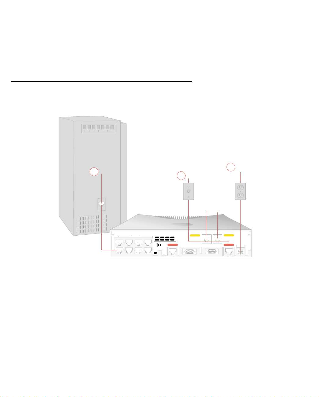
Identify the connectors and attach the cables
Identify the connectors and switches on the back panel and attach the necessary Netopia Router cables.
1 Ethernet
2 Telco
Phone
Ports
t
e
rn
e
th
E
8765
4321
Normal/Uplink
1
lc
e
T
Phone 2
ry
ilia
x
u
2
A
o
n
o
C
3 Power
Phone 1
1
r
o
e
lc
w
e
o
T
le
o
s
P
1. Connect one of the RJ-45 cables to any of the Ethernet ports on the router.
(If you are connecting the router to an existing Ethernet hub, use Ethernet port #1 on the router and set the
crossover switch to the Uplink position.)
2. Connect one end of one of the RJ-45 cables to the “T elco 1" or “Line 1" port, and the other end to your wall
outlet.
3. Connect the mini-DIN8 connector from the Power Adapter to the Power port, and plug the other end into an
electrical outlet.
You should now have: the power adapter plugged in; the Ethernet cable connected between the router and
your computer; and the telephone cables connected between the router and the wall outlets.
4. Insert your Netopia CD and follow the instructions to install an Internet browser and the Adobe Acrobat
Reader, if you don’t already have them.
Page 25
Making the Physical Connections 2-3
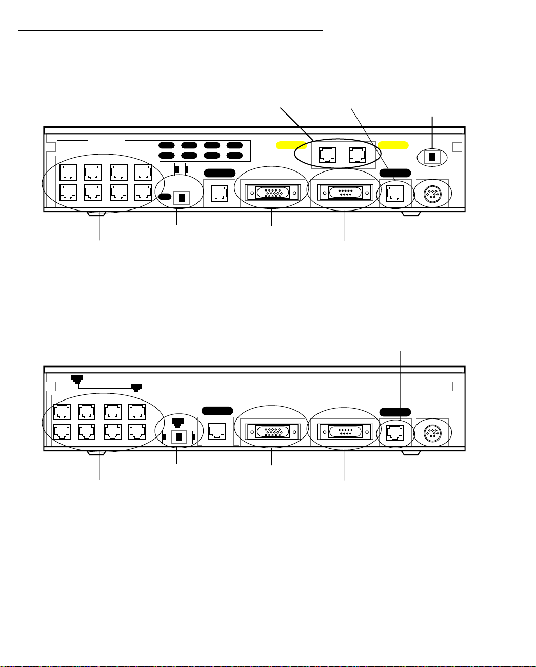
Netopia R3100 ISDN Router Back Panel Ports
The figure below displays the back of the Netopia R3100 ISDN Router (models R3100-S, SP, U, UP).
Netopia R3100 ISDN Router back panel (models R3100 -S, SP, U, and UP)
POTS ports (optional)
Line port
S/T Termination
switch
Ethernet
Crossover switch
8 port Ethernet hub
8
473
Normal/Uplink
1
625
1
Telco 2 Telco 1
Auxiliary Console Power
Auxiliary port
Console port
Phone 1Phone 2
Power port
Note: For simplicity, the remainder of this manual uses the figure above to illustrate connections.
The figure below displays the back of the Netopia R3100 Router for Copper Mountain IDSL connections
(R3100-I).
Netopia R3100 IDSL back panel (model R3100-I)
Line port
8
Ethernet
1
Crossover switch
8 port Ethernet hub
Normal
1
Uplink
Line 2
Auxiliary Console Power
Line 1
Auxiliary port
Console port
Power port
Page 26

2-4 User’s Reference Guide
The following table describes all the Netopia R3100 ISDN Router back panel ports.
Port Description
Power port A mini-DIN8 power adapter cable connection.
Line or Telco port A telephone-style jack labelled “T elco1” or “Line” for your WAN connection. Use
the “Telco 1" or “Line 1" port, NOT “Telco 2" or “Line 2."
Console port A DE-9 console port for a direct serial connection to the console screens. You
can use this if you are an experienced user and don’t want to use the preset
192.168.1.1 IP address in the router. See “Connecting a local terminal console
cable to your router” on page 6-3.
Auxiliary port An HD-15 auxiliary port for attaching an external modem or the optional
AppleTalk kit.
Crossover switch A crossover switch with Normal and Uplink positions. If you use Ethernet Port
#1 for a direct Ethernet connection between a computer and the router, set the
switch to the Normal position. If you are connecting the router to an Ethernet
hub, use Ethernet port #1 on the router and set the switch to the Uplink
position.
8-port Ethernet hub Eight Ethernet jacks. Y ou will use one of these to configure the Netopia R3100.
For a new installation, use the Ethernet connection. Y ou can either connect your
computer directly to any of the Ethernet ports on the router, or connect both
your computer and the router to an existing Ethernet hub on your LAN.
Alternatively, you can use the console connection to run console-based
management using a direct serial connection.
S/T Termination
switch
Netopia R3100 S/T models also provide an S/T termination switch. The S/T
termination switch on the Netopia R3100 back panel must be enabled to
terminate the S/T bus. To enable this parameter, the switch must be toggled to
the left.
Page 27

Port Description
2 Phone ports
(POTS models only)
Making the Physical Connections 2-5
Netopia R3100 models that support SmartPhone™ provide two RJ-11
telephone jacks for connecting analog devices, such as a telephone, facsimile
machine, or modem. * (UK users, see Note below)
The POTS ports are configured by default to support call hold, call retrieve and
the Flexible Call Offering (FCO) features known as Conference, Drop, and
Transfer.
■ While a call is active, you can initiate a single flash hook (or if your phone is
so equipped, press the Flash button) to start a second call. This will place
the first call on hold, and provide a dial tone. Two individual active calls per
channel are allowed.
■ Once the second call is established, you can switch back and forth
between the two calls by sending a single flash hook.
■ If you want to conference two calls that are active (one on hold, and one
live) send a double flash hook to activate the conference, followed by a
single flash hook to bridge the calls together. This process can be repeated
to bridge additional users to the conference, up to the maximum allowed by
the line's provisioning.
■ If a conference is active, you can drop the last call added to the conference
by issuing a double flash hook.
■ If you want to transfer an active conference (allow the two calls to continue
to talk after the Netopia R3100 has disconnected), send a single flash
hook to receive a new dial tone, followed by a double flash hook to initiate
the transfer.
For detailed configuration information, see “Using SmartPhone for Telephone
Services” on page 9-1.
* Note: Users in the United Kingdom may need to obtain a special US-to-UK style modular connector adapter.
Suitable adapters are available as follows:
Supplier Phone No Product Code
Black Box
0118 9655100 MCU9413
www.blackbox.co.uk
Maplins Electronics
01702 554000 VD36
www.maplin.co.uk
Page 28

2-6 User’s Reference Guide
Netopia R3100 ISDN Router Status Lights
The figure below represents the Netopia R3100 status light (LED) panel.
Netopia R3100 LED front panel
2 3 4 5 6 7 8 9 10 11 12 13 14 15 16171819 20 21
1
Link/Receive
Power
Management
Ready
Channel 1
WAN 1 WAN 2 Ethernet
Console
Channel 2
Auxiliary
Management
Ready
Channel 1
Channel 2
Traffic
Collision
The following table summarizes the meaning of the various LED states and colors:
When this happens... the LEDs...
Power is on 1 is green.
Data is transmitted or received over the ISDN D channel 2 flashes orange.
The WAN interface is operational 3 is green.
The WAN interface is inactive 3 is off.
The WAN interface detects a failure after line activation 3 flashes red.
Calls are setting up (voice or data) 4 and 5 flash green.
Data calls connect 4 and 5 are green.
Voice calls connect 4 and 5 flash green.
The line is carrying data traffic 4 and 5 pulse orange.
The respective Ethernet port is connected to the LAN 14 through 21 are green.
There is activity on the respective Ethernet ports 14 through 21 flash green.
Note: 8 through 11 are unused. Also, Console carrier (6) is ignored if the console is not configured for a
remote modem.
Page 29

Setting up your Router with the SmartStart Wizard 3-1
CCCChhhhaaaapppptttteeeerrrr 33
SSSSeeeettttttttiiiinnnngggg uuuupppp yyyyoooouuuurrrr RRRRoooouuuutttteeeerrrr wwwwiiiitttthhhh tttthhhheeee SSSSmmmmaaaarrrrttttSSSSttttaaaarrrrtttt WWWWiiiizzzzaaaarrrrdd
Once you’ve connected your router to your computer and your telecommunications line and installed a web
browser, you’re ready to run the Netopia SmartStart™ Wizard. The SmartStart Wizard will help you set up the
router and share the connection. The SmartStart Wizard walks you through a series of questions and based on
your responses automatically configures the router for connecting your LAN to the Internet or to your remote
corporate network.
The SmartStart Wizard will:
■ automatically check your Windows 95, 98, or NT PC’s TCP/IP configuration to be sure you can accept a
dynamically assigned IP address, and change it for you if it is not set for dynamic addressing
■ check the physical connection from your computer to your router without your having to enter an IP address
■ assign an IP address to your router
■ allow you to register with a new ISP if you don’t already have one (for analog modem and ISDN models).
For a list of ISPs that support Netopia Routers in North America, see the Netopia website at
http://www.netopia.com.
■ (for analog modem or ISDN models) allow you to enter your dial-up telephone numbers and other
information, dial up and test your connection to your chosen ISP or other remote site
This chapter covers the following topics:
33
dd
■ “Before running SmartStart” on page 2
■ “Setting up your Router with the SmartStart Wizard” on page 3
■ “Sharing the Connection” on page 10
Page 30

3-2 User’s Reference Guide
Before running SmartStart
Be sure you have connected the cables and power source as described in Step 1 “Connect the Router” guide
contained in your Netopia folio.
Before you launch the SmartStart application, make sure your computer meets the following requirements:
PC Macintosh
System
software
Connectivity
software
Connectivity
hardware
Browser
software
Notes:
• The computer running SmartStart must be on the same Ethernet cable segment as the Netopia R3100.
Repeaters, such as 10Base-T hubs between your computer and the Netopia R3100, are acceptable, but
devices such as switches or other routers are not.
• SmartStart for the PC will set your TCP/IP control panel to “Obtain an IP address automatically” if it is
not already set this way. This will cause your computer to reboot. If you have a specified IP address
configured in the computer, you should make a note of it before running SmartStart, in case you do not
want to use the dynamic addressing features built in to the Netopia Router and need to restore the fixed IP
address.
Windows 95, 98, or NT operating system MacOS 7.5 or later
TCP/IP must be installed and properly
configured. See “Configuring TCP/IP on
Windows 95, 98, or NT computers” on
page 3-10
Ethernet card (10Base-T) Either a built-in or third-party Ethernet card
Netscape Communicator™ or Microsoft Internet Explorer, included on the Netopia CD.
Required for web-based registration and web-based monitoring.
MacTCP or Open Transport TCP/IP must be
installed and properly configured. See
“Configuring TCP/IP on Macintosh
computers” on page 3-14.
(10Base-T)
Page 31

Setting up your Router with the SmartStart Wizard 3-3
Setting up your Router with the SmartStart Wizard
The SmartStart Wizard is tailored for your platform, but it works the same way on either a PC or a Macintosh.
Insert the Netopia CD, and in the desktop navigation screen that appears, launch the SmartStart Wizard
application.
SmartStart Wizard configuration screens
The screens described in this section are the default screens shipped on the Netopia CD. They
derive from two initialization (.ini) files included in the same directory as the SmartStart
application file. Your reseller or your ISP may have supplied you with customized versions of these
files.
■ If you have received a CD or diskette that has been customized by your reseller or ISP, you
can run the SmartStart Wizard directly from the CD or diskette and follow the instructions
your reseller or ISP provides. This makes your Netopia R3100 configuration even easier.
■ If you have received only the .ini files from your reseller or ISP, perform the following:
■ Copy the entire directory folder containing the SmartStart Wizard application from the
Netopia CD to your hard disk.
■ Copy the customized .ini files to the same directory folder that contains the SmartStart
Wizard application, allowing the copy process to overwrite the original .ini files.
■ Run the SmartStart Wizard from your hard disk. You can then follow the instructions your
reseller or ISP provides.
The SmartStart Wizard presents a series of screens to guide you through the preliminary configuration of a
Netopia R3100. It will then create a connection profile using the information you supply to it.
Welcome screen. The first screen welcomes you to the
SmartStart Wizard configuration utility.
Click the Next button after you have responded to the
interactive prompts in each screen.
The Help button will display useful information to assist
you in responding to the interactive prompts.
Page 32

3-4 User’s Reference Guide
Easy or Advanced options screen. Y ou can choose either
Easy or Advanced setup.
■ If you choose Easy, SmartStart automatically uses
the preconfigured IP addressing setup built into your
router. This is the best choice if you are creating a
new network or don’t already have an IP addressing
scheme on your new network.
If you choose Easy, you will see a “Connection Test
screen,” like the one shown below while SmartStart
checks the connection to your router.
■ If you choose Advanced, skip to page 3-9 now. The
SmartStart Wizard displays the “Router IP Address
screen” on page 3-9, in which you can choose ways
to modify your router’s IP address.
Easy option
Connection Test screen. SmartStart tests the
connection to the router. While it is testing the
connection, a progress indicator screen is displayed and
the router’s Ethernet LEDs flash.
When the test succeeds, SmartStart indicates success.
If the test fails, the wizard displays an error screen. If the test fails, check the following:
■ Check your cable connections. Be sure you have connected the router and the computer properly, using the
correct cables. Refer to the Step 1 “Connect the Router” sheet in your Netopia R3100 documentation folio.
■ Make sure the router is turned on and that there is an Ethernet connection between your computer and the
router.
■ Check the TCP/IP control panel settings to be sure that automatic IP Addressing (Windows) or DHCP
(Macintosh) is selected. If you are using a Windows PC, SmartStart will automatically detect a static IP
address and offer to configure the computer for automatic addressing. On a Macintosh computer, you must
manually set the TCP/IP Control Panel to DHCP. See “Configuring TCP/IP on Macintosh computers” on
page 3-14. If you currently use a static IP address outside the 192.168.1.x network, and want to continue
using it, use the Advanced option to assign the router an IP address in your target IP range. See “Advanced
option” on page 3-9.
■ If all of the above steps fail to resolve the problem, reset the router to its factory default settings and rerun
Page 33

Setting up your Router with the SmartStart Wizard 3-5
SmartStart. See the on-line User’s Reference Guide for instructions.
When the test is successful, SmartStart presents you with a different screen, depending on the type of router
you are configuring.
■ If you are configuring a router that defaults to an unswitched interface, such as IDSL, you will see the
“Additional Configuration screen,” shown below.
Additional Configuration screen. If you have a router that
has a permanent unswitched connection to your ISP, such
as an IDSL, SDSL, or Ethernet WAN interface router
attached to a cable modem, the Additional Configuration
screen appears.
You may want to do additional configuration to customize
your network environment. SmartStart lets you launch
your Telnet application. Click the Telnet button to launch
your Telnet application.
Advanced configuration options available via Telnet are
explained in “Console-based Management” on page 6-1.
However, if you need no further configuration options,
click Quit. Congratulations! You’re done!
■ If you are configuring an ISDN router, you may see the “ISDN Switch Type screen,” shown below,
displaying the possible switch types available for your region. This screen may not appear, if there is only
one switch type in use in your region or you are using a customized version of SmartStart, or the ISDN
Wizard has automatically detected your switch type.
ISDN Switch Type screen. If you have an ISDN router, the
ISDN Switch Type screen appears.
Select one of the supported ISDN switch types for your
ISDN line. Your telephone company should have provided
this information when your ISDN line was installed.
When you have done this, click Next.
Note: The switch types listed are different for different
regions. If your region has only one switch type, this
screen may not appear. In that case, skip to “Additional
ISDN Configuration screen” on page 3-6.
Page 34

3-6 User’s Reference Guide
Additional ISDN Configuration screen. For ISDN dial-up
connections, enter your Directory Numbers (DNs) and for
North America only, Service Profile Identifiers (SPIDs).
Your telephone company should have provided this
information on an information sheet when your ISDN line
was installed.
If no additional ISDN configuration information is needed,
this screen will not appear. Skip to “Manual or Automated
Connection Profile screen” on page 3-6 below.
Note: For some switch types, or if you have an
international router without the SmartPhone feature,
fewer fields are shown in this screen.
When you have done this, click Next.
The “Manual or Automated Connection Profile screen” on
page 3-6 shown below will appear.
■ If you are configuring an ISDN or a Dual Analog router, you will see the “Manual or Automated Connection
Profile screen,” shown below.
Manual or Automated Connection Profile screen. The
SmartStart Wizard asks you to select a method of
creating a connection profile. The connection profile tells
your router how to communicate with your ISP or other
remote site, such as your corporate office. Y ou can select
either ISP Automation or Manual Entry.
Options are explained below.
Make your selection and click Next.
If you select ISP Automation, SmartStart offers you the option of choosing one of several Netopia ISP
partners that support the Netopia R3100. You then see the “Internet Service Provider Selection screen” on
page 3-7.
If you select Manual Entry, you must be prepared with the following information. You must enter:
■ Your dial-up number, sometimes referred to as an ISP POP number
■ Your Login name and Password. (These are case-sensitive.)
■ Any PBX or Centrex phone system dialing prefix (such as “9” for an outside line)
■ Your PPP authentication method. Options are: PAP (Password Authentication Protocol), CHAP (Challenge
Handshake Authentication Protocol), or None. Most ISPs use PAP; this is the default.
■ Your Domain Name Server (DNS); this entry must be an IP address in dotted decimal format. (for example,
192.168.4.10, not “joe.isp.com”)
Page 35

Setting up your Router with the SmartStart Wizard 3-7
■ Optionally, an alternate DNS if your ISP provided one
If you select Manual Entry, the “Connection Profile screen,” shown below appears.
Internet Service Provider Selection screen. Select an
ISP from the list of Netopia ISP partners who have
provided information for automatic setup. Choose
Generic ISP if your ISP is not included on the list. If you
don’t already have an account with the selected ISP, call
and order service using the listed customer service
telephone number.
When you have done this, click Next.
■ Most ISPs will provide you with information for you to enter in the “Connection Profile screen” on page 3-7
(shown below) over the phone using the toll-free phone number shown in the scrolling list. Generally, they
will provide you with:
■ Your dial-up number, sometimes referred to as an ISP POP number
■ Your Login name and Password. (These are case-sensitive.)
Note: Your ISP may provide you with additional values such as “Remote IP Gateway” or “Subnet Mask.”
These entries are not required for the SmartStart Wizard to configure your router.
If you have a PBX or Centrex phone system, you may need a dialing prefix (such as “9” for an outside line).
You will enter that information in the “Connection Profile screen,” shown below.
Connection Profile screen. Enter your ISP-supplied
configuration information mentioned above. All fields
must be filled in except the Alternate DNS field if your ISP
does not provide one. If your ISP appeared in the
“Internet Service Provider Selection screen” on page 3-7
your ISP will already have provided much of the
information required for the connection, and these fields
will appear grayed-out.
When you have done this, click Next.
The “Name and Password screen” on page 3-8 appears;
this is where you enter the username and password for
your connection to your ISP.
Page 36

3-8 User’s Reference Guide
Name and Password screen. Enter the username and
password that identifies you to your ISP.
Note: Some automated profiles already specify name and
password for you. in this case, the screen is filled out for
you and automatically skipped.
When you have done this, click Next.
The SmartStart Wizard then posts your connection profile
information to your router.
Now the “Connection Profile Test screen,” (shown below)
appears. It allows you to test your connection to your ISP
using the connection profile you have just created.
Connection Profile Test screen. SmartStart tests your
connection profile by attempting to connect to your ISP.
To test the connection profile with your ISP, click Next.
While the test is running, SmartStart reports its progress
in a brief succession of dialog boxes as described below.
Available Line Test Progress screen. SmartStart tests to
see if the router can place calls on your telephone line.
While it is testing the connection, a dialog box is
displayed and the LEDs flash.
Connection Test Progress screen. SmartStart displays a
dialog box showing you that your connection profile is
being tested. If this test fails, check the physical
connections between the computer, the router, and the
wall jack or jacks. Check for errors in any manual entries
you made during the configuration process.
Final screen. When the connection tests successfully,
SmartStart displays a screen telling you that your
configuration is now complete.
In most cases, this SmartStart configuration is all that you need to get your router up and running and
connected to the Internet. However, you may want to take advantage of additional features or special
configuration options available through the console-based configuration interface. For detailed instructions, see
“Console-based Management” on page 6-1.
Page 37

Advanced option
Router IP Address screen. If you selected the Advanced
option in the “Easy or Advanced options screen” on
page 3-4, SmartStart asks you to choose between
entering the router’s current IP address and assigning an
IP address to the router.
If the router has already been assigned an IP address,
select the first radio button. If you do this, the “Known IP
Address screen,” appears (shown below.)
If you want to reconfigure the router with a new IP address
and subnet mask, select the second radio button. If you
do this, the “New IP Address screen” on page 3-10
appears.
When you have done this, click Next.
Known IP Address screen. SmartStart displays a
recommended address for the router based on the IP
address of the computer.
If you know the router has an IP address different from
the default value, enter it now. Otherwise, accept the
recommended address.
Setting up your Router with the SmartStart Wizard 3-9
When you have done this, click Next.
SmartStart tests the connection to your router.
SmartStart then returns you to an “Additional
Configuration screen” on page 3-5.
Page 38

3-10 User’s Reference Guide
New IP Address screen. If you want to change the router’s
IP address, you enter the new IP address, the subnet
mask, and the router’s serial number in this screen.
Remember, the serial number is on the bottom of the
router. It is also found in your documentation folio.
Note: Forcing a new IP address may turn off the Netopia
R3100’s IP address serving capabilities, if you assign an IP
address and subnet mask outside the router’s current IP
address serving pool. The Netopia R3100 does not allow
an invalid address to be served. Use this option with
caution.
When you have done this, click Next.
SmartStart forces the new IP address into the router, tests
the connection, and then resets the router.
SmartStart then returns you to the “Manual or Automated
Connection Profile screen” on page 3-6.
Sharing the Connection
Configuring TCP/IP on Windows 95, 98, or NT computers
Configuring TCP/IP on a Windows computer requires the following:
■ An Ethernet card (also known as a network adapter)
■ The TCP/IP protocol must be “bound” to the adapter or card
Page 39

Setting up your Router with the SmartStart Wizard 3-11
Dynamic configuration (recommended)
If you configure your Netopia R3100 using SmartStart, you can accept the dynamic IP address assigned by your
router. The Dynamic Host Configuration Protocol (DHCP) server, which enables dynamic addressing, is enabled
by default in the router. If your PC is not set for dynamic addressing, SmartStart will offer to do this for you
when you launch it. In that case, you will have to restart your PC and relaunch SmartStart. If you configure your
PC for dynamic addressing in advance, SmartStart need only be launched once. To configure your PC for
dynamic addressing do the following:
1. Go to the Start
Menu/Settings/Control
Panels and double click
the Network icon. From
the Network components
list, select the
Configuration tab.
2. Select TCP/IP-->Your Network Card. Then select
Properties. In the TCP/IP Properties screen (shown
below), select the IP Address tab. Click “Obtain an IP
Address automatically.”
3. Click on the DNS Configuration tab. Click Disable DNS.
DNS will be assigned by the router with DHCP.
4. Click OK in this window, and the next window. When
prompted, reboot the computer.
Note: Y ou can also use these instructions to configure other computers on your network to accept IP addresses
served by the Netopia R3100.
Page 40

3-12 User’s Reference Guide
Static configuration (optional)
If you are manually configuring for a fixed or static IP address, perform the following:
1. Go to Start Menu/Settings/Control Panels and double click the Network icon. From the Network
components list, select the Configuration tab.
2. Select TCP/IP-->Your Network Card. Then select Properties. In the TCP/IP Properties screen (shown
below), select the IP Address tab. Click “Specify an IP Address.”
Enter the following:
IP Address: 192.168.1.2
Subnet Mask: 255.255.255.0
This address is an example of one that can be used to configure the router with the Easy option in the
SmartStart Wizard. Your ISP or network administrator may ask you to use a different IP address and
subnet mask.
Page 41

Setting up your Router with the SmartStart Wizard 3-13
3. Click on the Gateway tab (shown below).
Under “New gateway,” enter
192.168.1.1. Click Add. This is the
Netopia R3100’s pre-assigned IP
address.
4. Click OK in this window, and the next window. When prompted, reboot the computer.
Click on the DNS Configuration tab. Click Enable DNS.
Enter the following
information:
Host: Type the name
you want to give to
this computer.
Domain: Type your
domain name. If you
don't have a domain
name, type your ISP's
domain name; for
example,
netopia.com.
DNS Server Search
Order: Type the
primary DNS IP
address given to you
by your ISP. Click
Add. Repeat this process for the secondary DNS.
Domain Suffix Search Order: Enter the same domain
name you entered above.
Note: You can also use these instructions to configure other computers on your network with manual or static
IP addresses. Be sure each computer on your network has its own IP address.
Page 42

3-14 User’s Reference Guide
Configuring TCP/IP on Macintosh computers
The following is a quick guide to configuring TCP/IP for MacOS computers. Configuring TCP/IP in a Macintosh
computer requires the following:
■ You must have either Open Transport or Classic Networking (MacTCP) installed.
Note: If you want to use the Dynamic Host Configuration Protocol (DHCP) server built into your Netopia
R3100 to assign IP addresses to your Macintoshes, you must be running Open Transport, standard in
MacOS 8, and optional in earlier system versions. You can have your Netopia R3100 dynamically assign IP
addresses using MacTCP; however, to do so requires that the optional AppleTalk kit be installed which can
only be done after the router is configured.
■ You must have built-in Ethernet or a third-party Ethernet card and its associated drivers installed in your
Macintosh.
Dynamic configuration (recommended)
If you configure your Netopia R3100 using SmartStart, you can accept the dynamic IP address assigned by your
router. The Dynamic Host Configuration Protocol (DHCP), which enables dynamic addressing, is enabled by
default in the router. To configure your Macintosh computer for dynamic addressing do the following:
1. Go to the Apple menu. Select Control Panels and then
TCP/IP.
2. With the TCP/IP window open, go to the Edit menu and
select User Mode. Choose Basic and click OK.
3. In the TCP/IP window, select “Connect via: Ethernet” and
“Configure: Using DHCP Server.”
Note: Y ou can also use these instructions to configure other computers on your network to accept IP addresses
served by the Netopia R3100.
Page 43

Setting up your Router with the SmartStart Wizard 3-15
Static configuration (optional)
If you are manually configuring for a fixed or static IP address,
perform the following:
1. Go to the Apple menu. Select Control Panels and then
TCP/IP or MacTCP.
2. With the TCP/IP window open, go to the Edit menu and
select User Mode. Choose Advanced and click OK.
Or, in the MacTCP window, select Ethernet and click the
More button.
3. In the TCP/IP window or in the MacTCP/More window, select or type information into the fields as shown in
the following table.
Option: Select/Type:
Connect via: Ethernet
Configure: Manually
IP Address: 192.168.1.2
Subnet mask: 255.255.255.0
Router address: 192.168.1.1
Name server address: Enter the primary and secondary name server
addresses given to you by your ISP
Implicit Search Path:
Starting domain name:
Enter your domain name; if you do not have a
domain name, enter the domain name of your ISP
4. Close the TCP/IP or MacTCP control panel and save the settings.
5. If you are using MacTCP, you must restart the computer. If you are using Open Transport, you do not need
to restart. These are the only fields you need to modify in this screen.
Note: You can also use these instructions to configure other computers on your network with manual or static
IP addresses. Be sure each computer on your network has its own IP address.
Page 44

3-16 User’s Reference Guide
Dynamic configuration using MacIP (optional)
If you want to use MacIP to dynamically assign IP addresses to the Macintosh computers on your network you
must install the optional AppleTalk feature set kit.
Note: You cannot use MacIP dynamic configuration to configure your Netopia R3100 ISDN Router because you
must first configure the router in order to enable AppleTalk.
Once the AppleTalk kit is installed, you can configure your Macintoshes for MacIP. To configure dynamically
using MacIP, perform the following:
Using Open Transport TCP/IP
1. Go to the Apple menu. Select Control Panels and then TCP/IP.
2. With the TCP/IP window open, go to the Edit menu and select User Mode. Choose Advanced and click OK.
3. In the TCP/IP window, select or type information into the fields as shown in the following table.
TCP/IP Option: Select/ Type:
Connect via: AppleTalk (MacIP)
Configure: Using MacIP server
MacIP Server zone: (select available zone)
Name server address: Enter the primary and secondary name server
addresses given to you by your ISP
Implicit Search Path:
Starting domain name:
Enter your domain name; if you do not have a
domain name, enter the domain name of your ISP
4. Close the TCP/IP control panel and save the settings.
These are the only fields you need to modify in these screens.
Page 45

Setting up your Router with the SmartStart Wizard 3-17
Using Classic Networking (MacTCP)
1. Go to the Apple Menu. Select Control Panels and then Network.
2. In the Network window, select EtherTalk.
3. Go back to the Apple menu. Select Control Panels and then MacTCP.
4. Select EtherTalk.
From the pull-down menu under EtherTalk, select an available zone; then click the More button.
In the MacTCP/More window select the Server radio button. If necessary, fill in the Domain Name Server
Information given to you by your administrator.
5. Restart the computer.
These are the only fields you need to modify in these screens.
Note: More information about configuring your Macintosh computer for TCP/IP connectivity through a Netopia
R3100 can be found in T echnote NIR_026, “Open T ransport and Netopia Routers,” located on the Netopia Web
site.
Page 46

3-18 User’s Reference Guide
Page 47

Connecting Your Local Area Network 4-1
CCCChhhhaaaapppptttteeeerrrr 44
CCCCoooonnnnnnnneeeeccccttttiiiinnnngggg YYYYoooouuuurrrr LLLLooooccccaaaallll AAAArrrreeeeaaaa NNNNeeeettttwwwwoooorrrrkk
This chapter describes how physically to connect the Netopia R3100 ISDN Router to your local area network
(LAN). Before you proceed, make sure the Netopia R3100 is properly configured. You can customize the
Router’s configuration for your particular LAN requirements using Console-based Management (see
“Console-based Management” on page 6-1).
This section covers the following topics:
■ “Overview” on page 4-1
■ “Readying computers on your local network” on page 4-2
■ “Connecting to an Ethernet network” on page 4-3
■ “Remote console” on page 4-5
■ “Connecting to a LocalTalk network” on page 4-6
44
kk
Overview
You can connect the Netopia R3100 to an IP or IPX network that uses Ethernet.
If you have purchased the AppleTalk feature expansion kit (order Netopia P/N TER/ATI), you can also connect
the Router to a LocalTalk network that uses PhoneNET cabling. On Netopia R3100 ISDN Routers, the AppleTalk
kit LocalTalk features require minimum firmware version 4.3.
See the sections later in this chapter for details on how to connect the Netopia R3100 to different types of
networks.
Page 48

4-2 User’s Reference Guide
Readying computers on your local network
PC and Macintosh computers must have certain components installed before they can communicate through
the Netopia R3100. The following illustration shows the minimal requirements for a typical PC or Macintosh
computer.
Application software
TCP/IP stack
Ethernet/EtherTalk/LocalTalk Driver
Your PC
or Macintosh
computer
To the Netopia R3100
Application software: This is the software you use to send e-mail, browse the World Wide Web, read
newsgroups, etc. These applications may require some configuration. Examples include the Eudora e-mail
client, and the web browsers Microsoft Internet Explorer and Netscape Navigator.
TCP/IP stack: This is the software that lets your PC or Macintosh communicate using Internet protocols.
TCP/IP stacks must be configured with some of the same information you used to configure the Netopia
R3100. There are a number of TCP/IP stacks available for PC computers. Windows 95 includes a built-in
TCP/IP stack. See “Configuring TCP/IP on Windows 95, 98, or NT computers” on page 3-10. Macintosh
computers use either MacTCP or Open Transport. See “Configuring TCP/IP on Macintosh computers” on
page 3-14.
Ethernet: Ethernet hardware and software drivers enable your PC or Macintosh computer to communicate on
the LAN.
EtherTalk and LocalTalk: These are AppleTalk protocols used over Ethernet. LocalTalk support is available as
an optional feature set upgrade.
Once the Netopia R3100 is properly configured and connected to your LAN, PC and Macintosh computers that
have their required components in place will be able to connect to the Internet or other remote IP networks.
Page 49

Connecting Your Local Area Network 4-3
Connecting to an Ethernet network
The Netopia R3100 supports Ethernet connections through its eight Ethernet ports. The Router automatically
detects which Ethernet port is in use.
You can connect either 10Base-T or 10/100 Ethernet networks to the Netopia R3100.
10Base-T
You can connect a standard 10Base-T Ethernet network to the Netopia R3100 using any of its available
Ethernet ports.
Netopia R3100 back panel
Ethernet
8
473
Normal/Uplink
1
8 port Ethernet hub
The Netopia R3100 in a 10Base-T network
625
1
Telco 2 Telco 1
Auxiliary Console Power
Ethernet
8
4
Normal/
1
Phone 1Phone 2
To connect your 10Base-T network to the Netopia R3100 through an Ethernet port, use a 10Base-T cable with
RJ-45 connectors.
Page 50

4-4 User’s Reference Guide
If you have more than eight devices to connect, you can attach additional devices using either a 10Base-T hub
or an EtherWave daisy chain, or some combination of both.
■ If you add devices connected through a 10 Base-T or 10/100 Ethernet hub, connect the hub to Ethernet
port number 1 on the Netopia R3100 and set the Normal/Uplink switch to Uplink.
When there are no more free ports on the 10Base-T hub, the network can be extended using EtherWave, a daisy-chainable
Ethernet solution from Farallon.
LaserWriter
EtherWave
Printer Adapter
EtherWave
ISA Card
MacintoshPC PC
EtherWave
NuBus Card
EtherWave
Transceiver
Ethernet
8
4
Normal/
1
10BASE-T
Hub
Page 51

Connecting Your Local Area Network 4-5
Remote console
You may want to add an external modem to your Auxiliary port. Remote modem terminal emulator setups can
dial in to the modem line and establish a remote console session. This allows an administrator with the
appropriate security to remotely configure your router for you.
Obtain the special external modem cable (Netopia Part Number TE6/DB25) either from your reseller or directly
from Netopia. Refer to the sheet of optional feature set add-ons in your Netopia R3100 documentation folio.
Netopia R3100 Auxiliary port for connecting an external modem
Ethernet
8
473
Normal/Uplink
1
625
1
Telco 2 Telco 1
Auxiliary Console Power
Phone 1Phone 2
Auxiliary connection port
HD-15 (female)
By default, the Auxiliary port on your Netopia R3100 is enabled for an external asynchronous modem. This
means that all you have to do is connect your modem to the Auxiliary port and configure its settings in the Line
Configuration screens under the WAN Configuration menu. For detailed configuration instructions see
“Auxiliary Port Configuration” on page 8-10.
For pinout information on the HD-15 to DB-25 modem cable, see “Pinouts for Auxiliary Port Modem Cable,” in
Appendix L, “Technical Specifications and Safety Information.”
Page 52

4-6 User’s Reference Guide
Connecting to a LocalTalk network
If you have purchased the AppleT alk Kit (part number TER/ATI), you can also connect the Router to an AppleT alk
network that uses either Ethernet or LocalTalk. Refer to the sheet of optional feature set add-ons in your
Netopia R3100 documentation folio.
The AppleTalk feature expansion kit includes a dual RJ-11 PhoneNET® connector that attaches to the Auxiliary
port on the Netopia R3100.
Netopia R3100 Auxiliary port for connecting to LocalTalk
Ethernet
8
473
Normal/Uplink
1
625
1
Telco 2 Telco 1
Auxiliary Console Power
Phone 1Phone 2
Auxiliary connection port
HD-15 (female)
Connect the male HD-15 end of the LocalTalk cable to the Auxiliary port on your Netopia R3100. Connect the
other end of the cable to your LocalTalk network. You can use only one connection on the Auxiliary port. You
cannot use both the PhoneNET connector and an external modem.
If your LocalTalk network is not based on standard PhoneNET cabling, use a PhoneNET-to-LocalTalk adaptor
cable available from Farallon. Connect the adaptor cable’s RJ-11 connector to the AppleTalk cable’s PhoneNet
connector. Connect the cable’s mini-DIN-3 connector to your LocalTalk network.
Be sure to observe the standard rules governing maximum cable lengths and limits on the number of nodes on
a PhoneNET network. The dual RJ-11 PhoneNET connector allows insertion in the LocalTalk daisy chain, or at
the end. If the device is connected at the end of the daisy chain, you must install the accompanying terminator.
Page 53

Wiring guidelines for PhoneNET cabling
Connecting Your Local Area Network 4-7
Topology
daisy chain n/a n/a 1800 ft.
backbone 4500 ft.
4-branch passive star* 1125 ft.
LocalTalk StarController
12-branch active star
* distance is per branch
Note: Make sure you do not connect your LocalTalk network to a Telco port or a POTS (Phone 1 and 2) port.
For detailed configuration instructions see “AppleTalk Setup” on page 13-1.
22 gauge
.642 mm
1372 m
343 m
3000 ft.
914 m
24 gauge
.510 mm
3000 ft.
229 m
750 ft.
229 m
2000 ft.
610 m
26 gauge
.403 mm
549 m
1800 ft.
549 m
450 ft.
137 m
1200 ft.
366 m
Page 54

4-8 User’s Reference Guide
Page 55

SmartView 5-1
CCCChhhhaaaapppptttteeeerrrr 55
SSSSmmmmaaaarrrrttttVVVViiiieeeeww
This chapter discusses SmartView, the Netopia R3100’s device and network web-based monitoring tool. This
tool can provide statistical information, report on current network status, record events, and help in diagnosing
and locating problems.
Topics covered in this chapter are:
■ “SmartView overview” on page 5-1
■ “General Machine information page” on page 5-2
■ “Connection Profiles page” on page 5-3
■ “Event history pages” on page 5-3
■ “Standard HTML web-based monitoring pages” on page 5-5
55
ww
SmartView overview
SmartView is a Java-based applet that runs in a Web browser window. It intermittently polls the router for
information to monitor the router’s state and event histories. SmartView should run under any Java Virtual
Machine (JVM)–enabled browser, and is therefore platform independent.
Note: The SmartView applet will only run under Java-enabled browsers. Be sure that the browser you are using
is at least Microsoft Internet Explorer Version 3.0 or higher, or Netscape Navigator Version 3.0 or Communicator
Version 4.0 or higher. If your browser does not meet this requirement, you can upgrade with a browser supplied
on the Netopia CD.
The information you can view about your router using SmartView is shown in the table below:
Machine Information
Model Profile Name Device
Firmware version Dial-out Profile WAN
Ethernet IP address Dial Number Update
Date Bandwidth Type
Time Dial Direction (In/Out)
LED status Remote Address
Connection Profile
Information
Gateway
DNS
History Logs
Page 56

5-2 User’s Reference Guide
Machine Information
Connection Profile
Information
DNS Alternate
Connect/Disconnect
History Logs
Navigating SmartView
You access the SmartView monitor by launching your web browser and entering the URL:
http://router_IP_Address/smartview.html
where router_IP_address is the address of your router. The default address is 198.162.1.1.
Once you have invoked the SmartView pages, bookmark SmartView in your browser for easy access.
General Machine information page
SmartView uses tabbed pages to categorize information and reduce the amount of information displayed at
once. Click on the tabs to display the different informational categories.
In addition to the static machine information about your router, such as model and firmware version, SmartView
displays a real-time visual representation of the Netopia R3100’s status lights (LEDs). This is particularly
useful if the router is located out of visual range, such as in a wiring closet.
Page 57

SmartView 5-3
Connection Profiles page
The Connection Profiles page displays the currently active Connection Profile, and any alternate profiles you
may have created. You can switch from one Connection Profile to another by disconnecting from one, and
connecting to another.
■ To hang up the current connection, and establish the one you select, click the Disconnect button for the
currently active Connection Profile.
■ Click the tab for the Connection Profile you want to activate.
■ Click the Connect Button for this Connection Profile.
Event history pages
The Netopia R3100 records certain relevant occurrences in event histories. Event histories are useful for
diagnosing problems because they list what happened before, during, and after a problem occurs. You can view
two different event histories: one for the router’s system and one for the WAN. The Netopia R3100’s built-in
battery backup prevents loss of event history from a shutdown or reset.
Page 58

5-4 User’s Reference Guide
The router’s event histories are structured to display the most recent events first, and to make it easy to
distinguish error messages from informational messages. Error messages are prefixed with an asterisk. Both
the WAN Event History and Device Event History pages retain records of up to 128 of the most recent events.
Which events are logged is controlled by the logging function in System Configuration. See “Logging” on
page 8-17.
Device Event History page
WAN Event History page
You can refresh the Event history logs by clicking the Update button.
Page 59

SmartView 5-5
Standard HTML web-based monitoring pages
You can also view connection profile information and event histories in the Web-based monitoring pages. These
pages are provided for users without Java-enabled browsers. Unlike the SmartView pages, they are not
dynamically updated.
You access the web-based monitoring pages by launching your web browser and entering the URL:
http://router_IP_address
where router_IP_address is the address of your router. The default address is 198.162.1.1.
■ To view your connection profile information, click the Connection Profiles icon.
■ To view event histories, click the Statistics icon.
■ To go to SmartView if your browser is Java-enabled, click the SmartView icon.
Page 60

5-6 User’s Reference Guide
Page 61

Console-based Management 6-1
CCCChhhhaaaapppptttteeeerrrr 66
CCCCoooonnnnssssoooolllleeee----bbbbaaaasssseeeedddd MMMMaaaannnnaaaaggggeeeemmmmeeeennnntt
This chapter describes how to use the Console-based management screens on your Netopia R3100 ISDN
Router. The console screens provide an alternate method for experienced users to configure their router
without using SmartStart. After completing the Easy Setup console screens, your router will be ready to connect
to the Internet or another remote site.
This chapter covers the following topics:
■ “About Console-based Management” on page 6-1
■ “Connecting through a Telnet session” on page 6-2
■ “Connecting a local terminal console cable to your router” on page 6-3
■ “Navigating through the console screens” on page 6-5
66
tt
About Console-based Management
Console-based management is a menu-driven interface for the capabilities built in to the Netopia R3100.
Console-based management provides access to a wide variety of features that the router supports. You can
customize these features for your individual setup. This section describes how to access the console-based
management screens.
Console-based management screens contain seven entry points to the Netopia Router configuration and
monitoring features. The entry points are displayed in the Main Menu shown below:
Netopia R3100-UP v4.3
Easy Setup...
WAN Configuration...
System Configuration...
Utilities & Diagnostics...
Statistics & Logs...
Quick Menus...
Quick View...
You always start from this main screen.
Page 62

6-2 User’s Reference Guide
Note about screen differences. Netopia R3100 models offering different feature sets will have variations in
the fields on certain screens. For example, there are switched (dial-up ISDN) and leased (Synchronous/Asynchronous, T1, and IDSL) line models, as well as models that offer feature subsets such as AppleTalk, SmartIP
(Network Address Translation and DHCP) and SmartPhone (Plain Old Telephone Service). Your own console
screens may look different from those illustrated in this manual.
■ The Easy Setup menus display and permit changing the values contained in the default Connection Profile
you created when you ran the SmartStart Wizard for initial configuration. Experienced users can also use
Easy Setup to initially configure the router directly through a console session without using SmartStart.
Easy Setup menus contain up to five descendant screens for viewing or altering these values. The number
of screens depends on whether you have optional features installed.
■ The WAN Configuration menu displays and permits changing your Connection Profile(s), creating or
deleting additional Connection Profiles, and configuring or reconfiguring the manner in which you may be
using the router to connect to more than one service provider or remote site.
■ The System Configuration menus display and permit changing:
■ Network Protocols Setup. See “IP Setup and Network Address Translation” on page 11-1.
■ Filter Sets (Firewalls). See “Security” on page 15-1.
■ IP Address Serving. See “IP address serving” on page 11-16.
■ Date and Time. See “Date and Time” on page 8-14.
■ Console Configuration. See “Connecting a local terminal console cable to your router” on page 6-3.
■ SNMP (Simple Network Management Protocol). See “SNMP” on page 14-12.
■ Security. See “Security” on page 15-1.
■ Upgrade Feature Set. See “Upgrade Feature Set” on page 8-16.
■ Telephone Setup. See “Using SmartPhone for Telephone Services” on page 9-1.
■ Logging. See “Logging” on page 8-17.
■ The Utilities & Diagnostics menus provide a selection of seven tools for monitoring and diagnosing the
router's behavior, as well as updating the firmware and rebooting the system. See “Utilities and
Diagnostics” on page 16-1 for detailed information.
■ The Statistics & Logs menus display nine sets of tables and device logs that show information about your
router, your network and their history. See “Statistics & Logs” on page 14-4 for detailed information.
■ The Quick Menus screen is a shortcut entry point to many of the most commonly used configuration
menus that are accessed through the other menu entry points.
■ The Quick View menu displays at a glance current real-time operating information about your router. See
“Quick View status overview” on page 14-1 for detailed information.
Connecting through a Telnet session
Features of the Netopia R3100 may be configured through the console screens.
Page 63

Console-based Management 6-3
Before you can access the console screens through Telnet, you must have:
■ a network connection locally to the router or IP access to the router through the WAN port. This could be
the same connection as the one you used with SmartStart and the "Easy" path. If you used the default
configuration for SmartStart, your IP address will be 192.168.1.1.
Note: Alternatively, you can have a direct serial console cable connection using the provided console cable
for your platform (PC or Macintosh) and the “Console” port on the back of the router. For more information
on attaching the console cable, see “Connecting a local terminal console cable to your router,” below.
■ Telnet software installed on the computer you will use to configure the router
Configuring Telnet software
If you are configuring your router using a Telnet session, your computer must be running a Telnet software
program.
■ If you connect a PC with Microsoft Windows, you can use a Windows Telnet application or simply run Telnet
from the Start menu.
■ If you connect a Macintosh computer, you can use the NCSA Telnet program supplied on the Netopia
R3100 CD. You install NCSA Telnet by simply dragging the application from the CD to your hard disk.
Connecting a local terminal console cable to your router
You can perform all of the System Configuration activities for your Netopia R3100 through a local serial console
connection using terminal emulation software, such as HyperTerminal provided with Windows 95 or 98 on the
PC, or ZTerm, included on the Netopia CD, for the Macintosh.
The Netopia R3100 back panel has a connector labeled “Console” for attaching the Router to either a PC or
Macintosh computer via the serial port on the computer. (On a Macintosh, the serial port is called the Modem
port or the Printer port.) This connection lets you use the computer to configure and monitor the Netopia R3100
via the console screens.
Ethernet
8
473
Normal/Uplink
1
625
1
Telco 2 Telco 1
Auxiliary Console Power
Phone 1Phone 2
Console connection port
DE-9 (male)
Page 64

6-4 User’s Reference Guide
To connect the Netopia R3100 to your computer for serial console communication, use the supplied dual
console cable connector end appropriate to your platform:
■ one DE-9 connector end attaches to a PC
■ the mini-DIN8 connector end attaches to a Macintosh
■ the DE-9 end of the Console cable attaches to the Netopia R3100’s Console port
If you are configuring your router via a terminal session, your computer must be running a standard terminal
emulation or communications software program, such as those used with modems.
■ If you connect a PC with Microsoft Windows 95 or NT, you can use the HyperTerminal application bundled
with the operating system.
■ If you connect a Macintosh computer, you can use the ZTerm terminal emulation program on the supplied
Netopia R3100 CD.
Launch your terminal emulation software and configure the communications software for the following values.
These are the default communication parameters that the Netopia R3100 uses.
Parameter Suggested Value
Terminal type PC: ANSI-BBS
Mac: ANSI, VT-100, or VT-200
Data bits 8
Parity None
Stop bits 1
Speed Options are: 9600, 19200, 38400, or 57600 bits per second
Flow Control None
Note: The router firmware contains an autobaud detection feature. If you are at
any screen on the serial console, you can change your baud rate and press
Return (HyperTerminal for the PC requires a disconnect). The new baud rate is
displayed at the bottom of the screen.
Page 65

Console-based Management 6-5
Navigating through the console screens
Use your keyboard to navigate the Netopia R3100’s configuration screens, enter and edit information, and
make choices. The following table lists the keys to use to navigate through the console screens.
To... Use These Keys...
Move through selectable items in a screen or pop-up menu Up, Down, Left, and
Right Arrow
To set a change to a selected item or open a pop-up menu of
options for a selected item like entering an upgrade key
Change a toggle value (Yes/No, On/Off) Tab
Restore an entry or toggle value to its previous value Esc
Move one item up Up arrow or Control + k
Move one item down Down arrow or Control + j
Display a dump of the device event log Control + e
Display a dump of the WAN event log Control + f
Refresh the screen Control + L
Go to topmost selectable item <
Go to bottom right selectable item >
To help you find your way to particular screens, some sections in this guide begin with a graphical path guide
similar to the following example:
Main
Menu
System
Configuration
Network Protocols
Setup
Return or Enter
IP Setup
This particular path guide shows how to get to the Network Protocols Setup screens. The path guide represents
these steps:
1. Beginning in the Main Menu, select the System Configuration item and press Return.
2. Select the Network Protocols item in the System Configuration screen and press Return.
3. Select the IP Setup item in the Network Protocols Setup screen and press Return.
To go back in this sequence of screens, use the Escape key.
Page 66

6-6 User’s Reference Guide
Page 67

Easy Setup 7-1
CCCChhhhaaaapppptttteeeerrrr 77
EEEEaaaassssyyyy SSSSeeeettttuuuupp
This chapter describes how to use the Easy Setup console screens on your Netopia R3100 ISDN Router. The
Easy Setup console screens provide an alternate method for experienced users to set up their router’s
Connection Profiles without using SmartStart. After completing the Easy Setup console screens, your router will
be ready to connect to the Internet or another remote site.
This chapter covers the following topics:
■ “Easy Setup console screens” on page 7-1
■ “Beginning Easy Setup” on page 7-3
■ “Configuring Frame Relay” on page 7-11
77
pp
Easy Setup console screens
Using four Easy Setup console screens, you can:
■ set up your switch type and datalink parameters
■ create or modify a Connection Profile for your Router for the connection to your ISP or remote location
■ set up IP addresses and IP address serving
■ password protect configuration access to your Netopia R3100 ISDN Router
How to access the Easy Setup console screens
To access the console screens, Telnet to the Netopia Router over your Ethernet network, or you can physically
connect with a serial console cable and access the Netopia Router with a terminal emulation program. See
“Connecting through a Telnet session” on page 6-2 or “Connecting a local terminal console cable to your
router” on page 6-3.
Note: Before continuing, make sure that you have the information that your telephone service provider, ISP, or
network administrator has given you to configure the Netopia Router.
The Netopia Router’s first console screen, Main Menu, appears in the terminal emulation window of the
attached PC or Macintosh when:
■ the Netopia Router is turned on
■ the computer is connected to the Netopia Router
■ the Telnet or terminal emulation software is running and configured correctly.
Page 68

7-2 User’s Reference Guide
A screen similar to the following appears:
Netopia R3100-UP v4.3
Easy Setup...
WAN Configuration...
System Configuration...
Utilities & Diagnostics...
Statistics & Logs...
Quick Menus...
Quick View...
Return/Enter goes to Easy Setup -- minimal configuration.
You always start from this main screen.
If you do not see the Main Menu, verify that:
■ the computer used to view the console screen has its serial port connected to the Netopia R3100’s
“Console” port or an Ethernet connection to one of its Ethernet ports. See “Connecting a local terminal
console cable to your router” on page 6-3 or “Connecting through a Telnet session” on page 6-2.
■ the Telnet or terminal emulation software is configured for the recommended values.
■ if you are connecting via the Console port, the console’s serial port is not being used by another device,
such as an internal modem, or an application. Turn off all other programs (other than your terminal
emulation program) that may be interfering with your access to the port.
■ you have entered the correct password, if necessary. Your Netopia R3100’s console access may be
password protected from a previous configuration. See your system administrator to obtain the password.
See Appendix A, “Troubleshooting,” for more suggestions.
Page 69

Beginning Easy Setup
To begin Easy Setup, select Easy Setup in the Main Menu, then press Return.
The Easy Setup screen appears. For an IDSL router, skip to “IDSL Easy Setup” on page 7-6.
ISDN Easy Setup
Circuit Type... ISDN, Switched
Switch Type... National ISDN-1 (NI-1) Detected
Directory Number 1: 5088324614 Detected
Directory Number 2: 5088324615 Detected
SPID 1: 50883246141 Pass
SPID 2: 50883246152 Pass
PBX Prefix:
Data Link Encapsulation... PPP
TO MAIN MENU NEXT SCREEN
Return/Enter to select <among/between> ...
Enter information supplied to you by your ISDN phone company.
Easy Setup 7-3
ISDN Easy Setup
Note: The ISDN Wizard is designed to automatically detect and configure most of your ISDN parameters for you,
without your having to enter anything except a PBX dialing prefix, if you need one. The steps described in this
section allow you to either accept the detected values or override them in a manual mode if you want to. As
soon as the router is physically connected to the ISDN line and powered on, it tries to detect the switch type,
directory numbers, and SPIDs. If it is successful, the screen above will be displayed with all the fields already
filled in, except the PBX Prefix field.
The Easy Setup Profile screen is where you configure the parameters that control the Netopia R3100’s
connection to a specific remote destination, usually an ISP or a corporate site.
On a Netopia R3100 ISDN Router you can add up to 15 more connection profiles, for a total of 16.
1. Select Circuit Type and press Return. From the pop-up menu, select:
ISDN, Switched if you have a switched ISDN line. This option covers the broadest range of U and ST
applications, and enables the ISDN Wizard automatic switch type and SPID detection for U interfaces and
defaults to Euro-ISDN for ST models, or
ISDN, Leased if you have a dedicated or leased (“nailed-up”) ISDN line that uses a single B channel (64K),
2B (128K), or the entire ISDN bandwidth of 2B+D (144K), or
IDSL, Ascend if your leased line service provider uses Ascend equipment (only available on U interfaces),
or
Page 70

7-4 User’s Reference Guide
IDSL, CMN if your leased line service provider uses Copper Mountain equipment (this is the default for
model R3100-I)
Note: The Switch Type, SPIDs, and Directory Numbers apply only to Switched ISDN service. If you select
either IDSL option, these fields are not displayed.
If you select ISDN, Leased as your circuit type, select Data Rate (kbps). From the pop-up menu, select the
appropriate B-channel, such as B1, B2, B1+B2, or 2B+D. Then skip to step 8.
It is possible to configure the router for any available circuit type: ISDN, Switched, ISDN, Leased,
IDSL, Ascend, or IDSL, CMN, depending on the switch gear you are connected to.
Netopia Model Default Circuit Type
Default Datalink
Encapsulation
Alternate Datalink
Encapsulation
ISDN, Switched (default) PPP Frame Relay, HDLC
ISDN, Leased PPP Frame Relay, HDLC
R3100-S and SP
IDSL, Ascend PPP None
IDSL, CMN Frame Relay ATM FUNI
ISDN, Switched (default) PPP Frame Relay, HDLC
ISDN, Leased PPP Frame Relay, HDLC
R3100-U and UP
IDSL, Ascend PPP None
IDSL, CMN Frame Relay ATM FUNI
IDSL, CMN (default) Frame Relay ATM FUNI
ISDN, Switched PPP Frame Relay, HDLC
R3100-I
ISDN, Leased PPP Frame Relay, HDLC
IDSL, Ascend PPP None
If you create a connection profile using a particular datalink encapsulation method, that profile will take
precedence whenever you connect to a line that uses that datalink encapsulation. If there is no connection
profile with the datalink encapsulation method that the line uses, the router will default to using the default
profile. See “The Default Profile” on page 8-6 for more information.
2. Select Switch Type and press Return. From the pop-up menu, select the switch protocol your ISDN service
provider uses.
North American options are:
■ Auto-Detect (the default): using this feature, the router will attempt to detect what type of switch you
are connecting to, what your directory numbers and SPIDs are, and configure itself accordingly.
If you select Auto-Detect from the popup menu, you may see the following screen if the router has not
Page 71

Easy Setup 7-5
already detected the switch type automatically. If you know your switch type, you can choose CANCEL
and select one of the other options manually. If the switch type has already been detected, the screen
(as shown on page 7-3) will so indicate. If the switch type has not been detected, the screen will indicate “Failed,” and you should select it manually from the other available options in the popup menu.
+----------------------------------------------------------------+
+----------------------------------------------------------------+
| |
| Attempting to determine Switch Type. This may take awhile. |
| If you want to proceed with manual configuration hit 'CANCEL'. |
| |
| Status: Detecting Switch Type |
| |
| CANCEL |
| |
+----------------------------------------------------------------+
■ National ISDN-1 (NI-1)
■ AT&T 5ESS Pt-to-Pt
■ AT&T 5ESS Multipoint
■ Nortel DMS100 Custom
European models: For European countries other than the United Kingdom, use the EuroISDN/ETSI setting.
United Kingdom users select United Kingdom - EuroISDN.
3. Select Directory Number 1.
The router attempted to detect your Directory Number(s) when you selected Auto-Detect in Step 1.
If it succeeded, the directory number(s) will be displayed, and the screen will indicate “Detected” (as
shown on page 7-3).
If it failed to detect your directory numbers, the fields will remain blank, and you must enter the primary
directory number as you would dial it, including area code. Do not enter access prefixes such as Centrex or
PBX prefixes like “9” (for an outside line). Press Return.
4. If you have a second directory number, select Directory Number 2 and enter the secondary directory
number as you would dial it, including area code. Press Return.
When you enter your directory number(s), the router will attempt to determine appropriate SPID numbers
for your connection. The following screen appears.
+----------------------------------------------------------------+
+----------------------------------------------------------------+
| |
| Attempting to determine SPID. This may take awhile. |
| If you want to proceed with manual configuration hit 'CANCEL'. |
| |
| Status: Detecting SPID |
| |
| CANCEL |
| |
+----------------------------------------------------------------+
Page 72

7-6 User’s Reference Guide
If the router detected your SPIDs successfully, the screen (as shown on page 7-3) displays them and
indicates “Pass,” meaning that the entered SPIDs initialized. If the SPIDs are entered incorrectly, the fields
will remain blank and the screen will indicate “Fail.” You must then re-enter them manually.
5. U models: Select SPID 1 and enter the primary SPID number. If you did not receive a SPID (AT&T 5ESS
custom point-to-point switches have no SPID), you should skip this and the following step.
Note: SPIDS and DNs may be entered with or without parentheses, commas, or dashes, as you are
accustomed to writing them.
6. U models: If you have a second SPID, select SPID 2 and enter the secondary SPID number.
Note: SPID1 and SPID2 are not displayed for switch types outside North America.
7. If you require a dialing prefix such as “9” to access an outside line on a PBX or Centrex phone system,
select PBX Prefix and enter your dialing prefix. Press Return.
8. Select Data Link Encapsulation and highlight the method of encapsulation that you want to use from the
pop-up menu. The choices offered are PPP, HDLC, or Frame Relay. The default for switched interfaces is
PPP. Press Return.
Note: If you select Frame Relay as your Datalink Encapsulation method, see “Configuring Frame Relay” on
page 7-11 for additional options and detailed instructions.
9. Select NEXT SCREEN and press Return. The “Easy Setup Profile” screen (shown on page 7-7) appears.
Any changes you make to the ISDN configuration now or in the future will take effect immediately. You do not
have to restart the router.
IDSL Easy Setup
The Easy Setup screen for an R3100-I IDSL router is different from the ISDN Easy Setup screen.
ISDN Easy Setup
Circuit Type... IDSL, CMN
+-------------+
+-------------+
Data Link Encapsulation... | Frame Relay |
| ATM FUNI |
+-------------+
TO MAIN MENU NEXT SCREEN
Page 73

Easy Setup 7-7
Choose your Data Link Encapsulation method. Frame Relay is the default. The choice of Frame relay or ATM
FUNI depends information supplied to you by your DSL service provider.
Easy Setup Profile
The Easy Setup Connection Profile screen is where you configure the parameters that control the ISDN Netopia
Router’s connection to a specific remote destination, usually another network.
Connection Profile 1: Easy Setup Profile
Number to Dial:
Address Translation Enabled: Yes
Local WAN IP Address: 0.0.0.0
Remote IP Address: 127.0.0.2
Remote IP Mask: 255.0.0.0
PPP Authentication... PAP
Send User Name:
Send Password:
PREVIOUS SCREEN NEXT SCREEN
Enter the directory number for the remote network connection.
Enter basic information about your WAN connection with this screen.
1. Select Number to Dial and enter the ISDN telephone number you received from your ISP. This is the
number the Netopia R3100 dials to reach your ISP. Enter the number as you would dial it, including any
required prefixes (such as area, access, and long-distance dialing codes).
If you selected ISDN, Leased, or either of the IDSL options, as your router’s Circuit Type in the ISDN Easy
Setup screen or if you have an IDSL router, Number to Dial will not be an available option. Other
differences include Frame Relay Management Type. For information on Frame Relay Management Type see
“Configuring Frame Relay” on page 7-11. Frame Relay is an alternative datalink encapsulation method for
use over unswitched connections. If this does not apply to your connection, you can skip the corresponding
sections.
2. To enable address translation, toggle Address Translation Enabled to Yes. For more information on
Network Address Translation, see Chapter 11, “IP Setup and Network Address Translation.”
Then select the Local WAN IP Address field. The default address is 0.0.0.0, which allows for dynamic
addressing, your ISP assigning an address each time you connect. However, you may enter another
address if you want to use static addressing.
Note: When using HDLC datalink encapsulation and Network Address Translation, you must use a static
address.
3. If your ISP uses Numbered (Interface-based Routing), select Local WAN IP Address and enter the local
WAN address your ISP gave you.
Page 74

7-8 User’s Reference Guide
When using numbered interfaces, the Netopia Router will use its local WAN IP address and subnet mask to
send packets to the remote router. Both routers have WAN IP addresses and subnet masks associated
with the connection.
If your ISP uses Unnumbered (System-based Routing) or your datalink encapsulation is not Frame Relay,
select Remote IP Address and enter the IP address your ISP gave you. Then select Remote IP Mask and
enter the IP subnet mask of the remote site you will connect to.
When using unnumbered interfaces, the Netopia Router will use either its local Ethernet IP address or its
NAT address (if so configured) and subnet mask to send packets to the remote router. Neither router has a
WAN IP address or subnet mask associated with this connection.
Note: If your ISP has not given you their IP or subnet mask addresses, then you may enter an IP address
such as 127.0.0.2, and an IP subnet mask such as 255.0.0.0. which are acceptable as defaults values,
and will typically be assigned at the time of connection.
4. For circuits with PPP enabled: Select the PPP Authentication pop-up menu and choose the type of
connection security your ISP told you to use (either None, PAP, CHAP, PAP-TOKEN, or CACHE-TOKEN). If
you choose PAP, CHAP, PAP-TOKEN, or CACHE-TOKEN, go to the next step. If your ISP does not use any of
these authentication methods, choose None and skip to the last step. When you create a connection
profile from Easy Setup, the default setting is PAP.
5. For circuits with PPP enabled: If your ISP uses PAP, select Send User Name and enter the user name your
ISP gave you to connect. Then select Send Password and enter the password.
If your ISP uses CHAP , select Send Host Name and enter the user name your ISP gave you to connect. Then
select Send Secret and enter the secret (CHAP term for password) your ISP gave you.
6. Select NEXT SCREEN and press Return. The IP Easy Setup screen appears.
Page 75

Easy Setup 7-9
IP Easy Setup
The IP Easy Setup screen is where you enter information about your Netopia Router’s:
■ IP address
■ Subnet mask
■ Default gateway IP address
■ Domain name server IP address
■ IP address serving information, such as the number of client IP addresses and the 1st client address; and
Y ou should consult with your network administrator to obtain the information you will need. For more information
about setting up IP, see “IP Setup and Network Address Translation” on page 11-1.
IP Easy Setup
Ethernet IP Address: 192.168.1.1
Ethernet Subnet Mask: 255.255.255.0
Domain Name:
Primary Domain Name Server: 192.168.1.10
Secondary Domain Name Server: 0.0.0.0
Default IP Gateway: 0.0.0.0
IP Address Serving: On
Number of Client IP Addresses: 100
1st Client Address: 192.168.1.3
PREVIOUS SCREEN NEXT SCREEN
Enter an IP address in decimal and dot form (xxx.xxx.xxx.xxx).
Set up the basic IP & IPX attributes of your Netopia in this screen.
1. Select Ethernet IP Address and enter the first IP address from the IP address range your ISP has given
you. This will be the Netopia Router’s IP address.
If Network Address Translation is enabled in the Easy Setup connection profile, the Ethernet IP Address
defaults to an address within a range reserved by the Internet address administration authority for use
within private networks, 192.168.1.1.
Because this is a private network address, it should never be directly connected to the Internet. Using NAT
for all your connection profiles will ensure this restriction. See “IP Setup and Network Address Translation”
on page 11-1 of this guide for more information.
2. Select Ethernet Subnet Mask and enter the subnet mask your ISP has given you. The Ethernet Subnet
Mask defaults to a standard class C mask, 255.255.255.0.
3. Select Domain Name and enter the domain name your ISP has given you.
4. Select Primary Domain Name Server and enter the IP address your ISP has given you.
Page 76

7-10 User’s Reference Guide
5. The Default IP Gateway defaults to the remote IP address you entered in the Easy Setup connection
profile. If the Netopia Router does not recognize the destination of any IP traffic, it forwards that traffic to
this gateway – set to 127.0.0.2 if your ISP does not otherwise specify.
Do not confuse the remote IP address and the default gateway’s IP address with the block of local IP
addresses you receive from your ISP. You use the local IP addresses for the Netopia R3100’s Ethernet port
and for IP clients on your local network. The remote IP address and the default gateway’s IP address
should point to your ISP’s router.
6. To use DHCP and (if installed) MacIP address serving, toggle IP Address Serving to On.
Note: For information about dynamic IP address serving, see “IP Setup and Network Address Translation”
on page 11-1.
7. If IP Address Serving is On, select Number of Client IP Addresses. Then enter the number of available
host addresses for the Netopia R3100 ISDN Router to allocate to the client computers on your network.
This number defaults to the balance of the subnet addresses above the Netopia Router’s address.
8. If IP Address Serving is On, select 1st Client Address and enter the first IP address in the set of allocated
served IP addresses.
Note: On a Netopia R3100 the factory default IP Address serving settings are:
1st Client Address: 192.168.1.3
Number of Client IP Addresses: unlimited models:100; limited models: number of users minus 1
(this allows for one static address at 192.168.1.2 for the server)
The values you set in this screen are displayed in the “Quick View status overview” shown on page 14-2.
9. Press Return. The Easy Setup Security Configuration screen appears.
Easy Setup Security
The Easy Setup Security Configuration screen lets you password-protect your Netopia R3100. Input your Write
Access Name and Write Access Password with names or numbers totaling up to eleven digits.
If you password protect the console screens, you will be prompted to enter the name and password you have
specified every time you log in to the console screens. Do not forget your name and password. If you do, you
will be unable to access any of the configuration screens.
Additional security features are available. See “Security” on page 15-1.
Page 77

Easy Setup 7-11
Easy Setup Security Configuration
It is strongly suggested that you password-protect configuration access to your
Netopia. By entering a Name and Password pair here, access via serial, PC Card,
Telnet, SNMP and Web Server will be password-protected.
Be sure to remember what you have typed here, because you will be prompted for
it each time you configure this Netopia.
Write Access Name:
Write Access Password:
PREVIOUS SCREEN TO MAIN MENU RESTART DEVICE
Configure a Configuration Access Name and Password here.
The final step in configuring the Easy Setup console screens is to restart the Netopia R3100, so the
configuration settings take effect.
1. Select RESTART DEVICE. A prompt asks you to confirm your choice.
2. Select CONTINUE to restart the Netopia Router and have your selections take effect.
Note: You can also restart the system at any time by using the restart utility (see “Restarting the system” on
page 16-12) or by turning the Netopia Router off and on with the power switch.
Easy Setup is now complete.
Configuring Frame Relay
Frame Relay is an alternative datalink encapsulation method for use over unswitched connections. If this does
not apply to your connection, you can skip the corresponding sections.
You can specify Frame relay as your Datalink Encapsulation method in either of two ways:
■ the “Easy Setup Frame Relay screens” on page 7-12 or
■ the “WAN Configuration Frame Relay screens” on page 7-13
Page 78

7-12 User’s Reference Guide
Easy Setup Frame Relay screens
Main
Menu
ISDN Easy Setup
Circuit Type... Switched
Switch Type... EuroISDN/ETSI
Directory Number 1: 5105776430
Directory Number 2: 5105776431
PBX Prefix: +-------------+
+-------------+
Data Link Encapsulation... | PPP |
| HDLC |
| Frame Relay |
+-------------+
TO MAIN MENU NEXT SCREEN
Easy
Setup
For IDSL routers, Frame Relay encapsulation is the default.
ISDN
Easy Setup
IDSL Easy Setup
+-------------+
+-------------+
Data Link Encapsulation... | Frame Relay |
| ATM FUNI |
+-------------+
TO MAIN MENU NEXT SCREEN
Return/Enter goes to new screen.
Enter information supplied to you by your ISDN phone company.
Page 79

Easy Setup 7-13
WAN Configuration Frame Relay screens
The ISDN Line Configuration menu also offers the options of either PPP, HDLC, or Frame Relay as your datalink
encapsulation method.
Main
Menu
ISDN Line Configuration
Circuit Type... Switched
Switch Type... EuroISDN/ETSI
Directory Number 1: 5105776430
Directory Number 2: 5105776431
PBX Prefix: +-------------+
+-------------+
Data Link Encapsulation... | PPP |
| HDLC |
| Frame Relay |
+-------------+
WAN
Configuration
For IDSL routers, Frame Relay is the default.
WAN
Setup
ISDN Line
Configuration
IDSL Line Configuration
Data Link Encapsulation... Frame Relay
Aux Serial Port... LocalTalk
Enter information supplied to you by your ISDN phone company.
Page 80

7-14 User’s Reference Guide
Frame Relay configuration
If you chose Frame Relay as your datalink encapsulation type you can now configure the Frame Relay options.
WAN Configuration
WAN (Wide Area Network) Setup...
Display/Change Connection Profile...
Add Connection Profile...
Delete Connection Profile...
Default Answer Profile...
Scheduled Connections...
Frame Relay Configuration...
Frame Relay DLCI Configuration...
Establish WAN Connection...
Disconnect WAN Connection...
Return/Enter for WAN line configuration.
From here you will configure yours and the remote sites' WAN information.
From the WAN Configuration screen, select WAN Setup, then select the Frame Relay Configuration option and
press Return. The Frame Relay Configuration screen appears.
Frame Relay Configuration
LMI Type... ANSI (Annex D)
T391 (Polling Interval in secs): 10
N391 (Polls/Full Status Cycles): 6
N392 (Error Threshold): 3
N393 (Monitored Event Window): 4
Tx Injection Management... Standard
Default CIR: 64000
Default Bc: 64000
Default Be: 0
Congestion Management Enabled: No
Maximum Tx Frame Size: 1520
Return/Enter goes to new screen.
Enter Information supplied to you by your telephone company.
Page 81

Easy Setup 7-15
Note: The default configuration for the model R3100-I is No LMI as an LMI Type and DLCI 16 is statically
configured. This is appropriate for current versions of the Copper Mountain DSLAM firmware. Future versions of
the Copper Mountain firmware may support multiple statically configured DLCIs or DLCIs other than 16, or an
LMI setting other than No LMI. In that case there may be no need to statically configure DLCIs at all since the
router may be able to detect what DLCIs are configured between it and the DSLAM. Consult your service
provider, CE200 documentation, or technical notes from Copper Mountain for DSLAM configuration.
The following configuration information is provided for options available in future versions of the Copper
Mountain firmware.
1. Select LMI Type (Link Management Type) and press Return. From the pop-up menu, highlight either ANSI
(Annex D), CCITT (Annex A), LMI, or No LMI. The default is No LMI. Press Return.
See “Frame Relay DLCI configuration” on page 7-16 for instructions.
Specifying the Link Management Type is the first step in configuring Frame Relay.
■ If you select an LMI Type (Link Management Type) other than None, the T391 option specifies the
number of seconds between the Status Enquiry messages. The default setting is 10.
■ The N391 option specifies the frequency of full status polls, in increments of the basic (T391) polling
cycle. The default setting is 6.
■ The N392 option specifies the maximum number of (link reliability, protocol, and sequence number)
error events that can occur within the N393 sliding window. If an N392 threshold is exceeded, the
switch declares the Netopia Router inactive. The default setting is 3.
■ The N393 option allows the user to specify the width of the sliding N392 monitored event window . The
default setting is 4.
2. Select Tx Injection Management and press Return. From the pop-up menu, highlight Standard if you want
the frames on your line that exceed the configured service parameters to be dropped at the router,
Buffered if you want the frames on your line that exceed the link capacity to be delayed until the link is less
busy, or None if you want all of the frames on your line to be transmitted. Press Return.
Note: If you select None as the Tx Injection Management type, the three Tx Injection Management options
listed below will remain hidden. Go to step 4.
If you select Standard or Buffered as the Tx Injection Management type, then the Default CIR, Bc, and Be
values will appear (in the corresponding fields below the Tx Injection Management field) in order for you to
define the parameters the management algorithm.
■ The Default CIR (CIR also referred to as Committed
Information Rate) represents the average capacity available to a given PVC (Permanent Virtual Circuit)
or DLCI (Data Link Connection Identifier). This setting defaults to 64000, but you may modify the
capacity rate if this setting will not be applicable to you.
■ The Default Bc (Bc also referred to as Committed Burst Size) represents the maximum amount of data
that your Frame Relay service provider agrees to transfer from a given PVC (Permanent Virtual Circuit)
or DLCI (Data Link Connection Identifier). This setting defaults to 64000, but you may change the
capacity rate if this setting needs to be modified.
■ The Default Be (Be also referred to as Excess Burst Size) represents the maximum amount of data
that your Frame Relay service provider will attempt to deliver to a given PVC (Permanent Virtual Circuit)
or DLCI (Data Link Connection Identifier). This setting defaults to 0, but you may change the capacity
rate if this setting needs to be modified.
Page 82

7-16 User’s Reference Guide
Note: Some Frame Relay service providers allow for over-subscription of the DLCIs, which occurs when the
total number of CIRs for all PVCs exceeds the line rate setup.
3. Select Congestion Management Enabled and toggle to Yes or No depending on whether you use this
selection. Press Return.
If Congestion Management is enabled, this option causes the Netopia Router to use in-bound FECNs
(Forward Explicit Congestion Notification). This feature is designed to notify you that congestion avoidance
procedures should be initiated where applicable for traffic in the same direction as the received frame. It
indicates that the frame in question, has encountered congested resources.
Note: The Congestion Management Enabled field will only appear if Standard or Buffered is selected as
the option from the Tx Injection Management field.
4. Select Maximum Tx Frame Size and press Return. The default is automatically set to a value suitable for
encapsulating a full ethernet packet’s transmission load, however you may change the Maximum Frame
Size to suit your networks transmission load. Press Return.
You are now done configuring the Frame Relay Configuration screen. Press the Escape key to return to the WAN
Configuration screen. If you need to configure your DLCIs, go to the next section.
Frame Relay DLCI configuration
If you selected None as your LMI Type then you will need to manually configure your DLCIs.
A Frame Relay DLCI is a set of parameters that tells the Netopia Router how to initially connect to a remote
destination.
The Netopia Router supports up to 16 different Frame Relay DLCI profiles.
Each Frame Relay DLCI configuration you set up allows the Netopia Router to connect your network to another
network that uses IP or IPX over Frame Relay.
Page 83

Easy Setup 7-17
To go to the Frame Relay DLCI configuration screen, select Frame Relay DLCI Configuration in the WAN
Configuration screen.
Frame Relay DLCI Configuration
Display/Change DLCIs...
Add DLCI...
Delete DLCI...
Add, delete, and modify DLCIs from here.
Displaying a Frame Relay DLCI configuration table
To display a view-only table of the Frame Relay DLCIs, select Display/Change DLCIs in the Frame Relay DLCI
Configuration screen, and press Return.
The Frame Relay DLCI Configuration table is a handy way to quickly view the DLCI names and DLCI numbers that
you attribute to your Frame Relay profiles.
Frame Relay DLCI Configuration
+-DLCI Name----------DLCI Number-+
+--------------------------------+
| |
| DLCI 16 16 |
| |
| |
| |
| |
| |
| |
| |
| |
| |
| |
| |
| |
| |
| |
+--------------------------------+
Up/Down Arrow Keys to select, ESC to dismiss, Return/Enter to Edit.
Page 84

7-18 User’s Reference Guide
Changing a Frame Relay DLCI configuration
To modify a Frame Relay DLCI configuration, select Display/Change DLCIs in the Frame Relay DLCI
Configuration screen.
Select a DLCI Name from the table and press Return to go to the Change DLCI screen. The parameters in this
screen are the same as the parameters in the Add DLCI screen. To find out how to set them, see “Adding a
Frame Relay DLCI configuration” on page 7-19.
Change DLCI
DLCI Name: DLCI 33
DLCI Enabled: Yes
DLCI Number (16-991): 32
Remote IP Address: 2.0.0.2
Page 85

Easy Setup 7-19
Adding a Frame Relay DLCI configuration
To add a new Frame Relay DLCI, select Add DLCI in the Frame Relay DLCI Configuration screen and press
Return. The Add DLCI screen appears.
Add DLCI
DLCI Name: DLCI 16
DLCI Enabled: Yes
DLCI Number (16-991): 16
Remote IP Address: 0.0.0.0
Data Flow Parameters---------------Use Default---------Value----
CIR: Yes
Bc: Yes
Be: Yes
ADD DLCI NOW CANCEL
Return accepts * ESC cancels * Left/Right moves insertion point * Del deletes.
Here you configure the parameters for a single DLCI (Data Link Circuit ID).
1. Select DLCI Name and enter a name for this individual Frame Relay DLCI profile. It can be any name you
wish. For example: the name of your ISP or remote branch your connecting to such as the corporate
headquarters of your company.
Note: The Netopia Router allows Frame Relay DLCIs to be named, so that you can easily reference and
differentiate them. This is accomplished by giving a DLCI Name to a DLCI Number.
2. Select DLCI Enabled and toggle it to Yes to activate the profile. If you disable this profile, the Netopia
Router will automatically disable and block access to a specific remote DLCI.
3. Select DLCI Number (16-991) and enter a number for this individual DLCI. Check with your Frame Relay
provider to find out what numbers are allocated for each of your DLCI profiles. The DLCI number range
should fall within the range of 16-991.
4. Select Remote IP Address and enter the remote IP address your ISP or network administrator gave you
that represents the remote sites IP address for their router. Press Return.
If you select Standard or Buffered as the Tx Injection Management type in the Frame Relay Configuration screen
go to the next bulleted item below. If you selected None in the Frame Relay Configuration screen go to step 6.
Below the Remote IP Address field, the following Data Flow Parameters appear:
■ The CIR (Committed Information Rate) represents the average capacity available to a given PVC (Per-
manent Virtual Circuit) or DLCI (Data Link Connection Identifier). The setting defaults to 64000, but
you may modify the capacity rate by toggling the selection in the Use Default field to No. You can then
enter a different capacity rate in the Value field.
■ The Bc (Committed Burst Size) represents the maximum amount of data that your Frame Relay service
provider agrees to transfer from a given PVC (Permanent Virtual Circuit) or DLCI (Data Link Connection
Page 86

7-20 User’s Reference Guide
Identifier). The setting defaults to 64000, but you may modify the committed burst size by toggling the
selection in the Use Default field to No. You can then enter a different committed burst size in the
Value field.
■ The Be (Excess Burst Size) represents the maximum amount of data that your Frame Relay service
provider will attempt to deliver to a given PVC (Permanent Virtual Circuit) or DLCI (Data Link Connection
Identifier). The setting defaults to 0, but you may modify the excess burst size by toggling the selection
in the Use Default field to No. You can then enter a different excess burst size in the Value field.
Note: Some Frame Relay service providers allow for over-subscription of the DLCIs, which occurs when the
total number of CIRs for all PVCs exceeds the line rate set up.
5. Select ADD DLCI NOW to save the current static Frame Relay DLCI profile that you have just entered, and
press Return to go back to the Frame Relay DLCI Configuration screen. Alternately, you can cancel the
Frame Relay DLCI profile you have just created by selecting CANCEL to exit the Add DLCI screen.
Deleting a Frame Relay DLCI configuration
To delete a Frame Relay DLCI configuration, select Delete DLCI in the Frame Relay DLCI Configuration screen
and press Return to display the Frame Relay DLCI configuration table.
Frame Relay DLCI Configuration
+-DLCI Name----------DLCI Number-+
+--------------------------------+
| joe 16 |
+------------------------------------------------------------------------+
+------------------------------------------------------------------------+
| |
| Are you sure you want to delete this DLCI? |
| |
| CANCEL CONTINUE |
| |
| |
+------------------------------------------------------------------------+
| |
| |
| |
| |
| |
| |
+--------------------------------+
1. Highlight the Frame Relay DLCI configuration you wish to delete. Press Return.
2. A Frame Relay DLCI Configuration table appears with a prompt asking you if you want to delete the
connection profile you have just highlighted. Select CONTINUE if you wish to delete this DLCI or CANCEL if
you do not.
You are now finished configuring the Frame Relay DLCI Configuration screen.
Page 87

PPPPaaaarrrrtttt IIIIIIII:::: AAAAddddvvvvaaaannnncccceeeedddd CCCCoooonnnnffffiiiigggguuuurrrraaaattttiiiioooonn
nn
Page 88

User’s Reference Guide
Page 89

WAN and System Configuration 8-1
CCCChhhhaaaapppptttteeeerrrr 88
WWWWAAAANNNN aaaannnndddd SSSSyyyysssstttteeeemmmm CCCCoooonnnnffffiiiigggguuuurrrraaaattttiiiioooonn
This chapter describes how to use the console-based management screens to access and configure advanced
features of your Netopia R3100 ISDN Router. Y ou can customize these features for your individual setup. These
menus provide a powerful method for experienced users to set up their router’s connection profiles and system
configuration.
This section covers the following topics:
■ “Creating a new Connection Profile” on page 8-1
■ “The Default Profile” on page 8-6
■ “Auxiliary Port Configuration” on page 8-10
■ “System Configuration screens” on page 8-11
■ “System Configuration features” on page 8-12
88
nn
Creating a new Connection Profile
Connection Profiles define the telephone and networking protocols necessary for the router to make a remote
connection. A Connection Profile is like an address book entry describing how the router is to get to a remote
site, or how to recognize and authenticate a remote user dialing in to the router. For example, to create a new
Connection Profile, you navigate to the WAN Configuration screen from the Main Menu, and select Add
Connection Profile.
Main
Menu
WAN
Configuration
Add Connection
Profile
Page 90

8-2 User’s Reference Guide
The Add Connection Profile screen appears.
Add Connection Profile
Profile Name: Profile 02
Profile Enabled: Yes
IP Enabled: Yes
IP Profile Parameters...
IPX Enabled: No
Data Link Encapsulation... PPP
Data Link Options...
Telco Options...
ADD PROFILE NOW CANCEL
Return accepts * ESC cancels * Left/Right moves insertion point * Del deletes.
Configure a new Conn. Profile. Finished? ADD or CANCEL to exit.
On a Netopia R3100 ISDN Router you can add up to 15 more connection profiles, for a total of 16.
A Netopia R3100 IDSL Router can only use one at a time.
1. Select Profile Name and enter a name for this connection profile. It can be any name you wish. For
example: the name of your ISP.
2. Toggle the Profile Enabled value to Yes or No. The default is Yes.
3. Select IP Profile Parameters and press Return. The IP Profile Parameters screen appears.
IP Profile Parameters
Address Translation Enabled: Yes
Local WAN IP Address: 0.0.0.0
Remote IP Address: 0.0.0.0
Remote IP Mask: 0.0.0.0
Filter Set...
Remove Filter Set
Receive RIP: Off
Toggle to Yes if this is a single IP address ISP account.
Configure IP requirements for a remote network connection here.
Page 91

WAN and System Configuration 8-3
4. Toggle or enter any IP Parameters you require and return to the Add Connection Profile screen by pressing
Escape. For more information, see “IP Setup and Network Address Translation” on page 11-1.
5. If you will be connecting with an IPX remote network, toggle IPX Enabled to Yes, and press Return.
Otherwise, accept the default No.
If you enable IPX routing, an IPX Profile Parameters menu item becomes available. Select IPX Profile
Parameters and press Return. The IPX Profile Parameters screen appears.
IPX Profile Parameters
Remote IPX Network: 00000000
Path Delay: 10
NetBios Packet Forwarding: Off
Incoming Packet Filter Set... <<NONE>>
Outgoing Packet Filter Set... <<NONE>>
Incoming SAP Filter Set... <<NONE>>
Outgoing SAP Filter Set... <<NONE>>
Periodic RIP Timer: 60
Periodic SAP Timer: 60
Configure IPX requirements for a remote network connection here.
6. T oggle or enter any IPX Parameters you require and return to the Add Connection Profile screen by pressing
Escape. For more information, see “IPX Setup” on page 12-1.
Page 92

8-4 User’s Reference Guide
7. Select Datalink Options and press Return. The Datalink Options screen appears.
Datalink (PPP/MP) Options
Data Compression... Ascend LZS
Send Authentication... PAP
Send User Name:
Send Password:
Receive User Name:
Receive Password:
Channel Usage... Dynamic
Bandwidth Allocation... BAP
Maximum Packet Size: 1500
In this Screen you will configure the PPP/MP specific connection params.
You can accept the defaults, or change them if you wish. Y ou can also specify user name and password for
both outgoing and incoming calls. the Send User Name/Password parameters are used to specify your
identity when dialing out to a remote location. The Receive User Name/Password parameters are used
when receiving dial-in clients such as via RAS configuration.
The Channel Usage pop-up menu allows you to choose how many lines your connections may use, and
whether or not they are preemptable. Supported options are:
Option Behavior
Dynamic 1 to 3 channels, if available, will be used, depending on traffic volume
1-Channel Only 1 channel will be used
2-Channels 2 channels will be preferred
2-Channel Preemptable 2 channels will be used, but 1 may be reallocated
Note: The Bandwidth Allocation pop-up options are: Off, Auto, BAP or MP+. BAP is the default. You should
only choose one of the other options if you are specifically advised to do so by your ISP or administrator.
Return to the Add Connection Profile screen by pressing Escape.
Page 93

WAN and System Configuration 8-5
8. Select Telco Options and press return. the Telco Options screen appears.
Note: For IDSL routers, which do not initiate dial-up connections, this option does not appear.
Telco Options
Initiate Data Service... 64 kb/sec
Dial... Dial In/Out
Number to Dial:
Alternate Site to Dial:
Dial on Demand: Yes
Idle Timeout (seconds): 300
CNA Validation Number:
Callback: No
Maximum connect time (HH:MM): 0:00
Return/Enter to select data rate/class of service.
In this Screen you configure options for the ways you will establish a link.
Select Dial and press Return. A pop-up menu appears. You can select the dialing options for this
Connection Profile as Dial In Only, Dial Out Only, or Dial In/Out.
You can:
■ select a type of data service to initiate, 64 kb/sec (the default), 56 kb/sec, or Speech
■ add the number to dial for this Connection Profile
■ add an alternate number
■ change any of the default parameter settings
■ if you have enabled Call Accounting (see “Cost control feature -- call accounting” on page 10-1) you
can set the Maximum connect time for this connection profile by entering the hours and minutes in
HH:MM format. When aggregate usage for this profile reaches this threshold, the profile becomes temporarily disabled until the limit is raised or the counters are reset (see “Viewing call accounting statis-
tics” on page 10-2). If Call Accounting is not enabled, this field does not appear.
When you are finished with these entries, press Escape to return to the Add Connection Profile screen.
9. Select ADD PROFILE NOW and press Return. Your new Connection Profile will be added.
Page 94

8-6 User’s Reference Guide
If you want to view the Connection Profiles in your router, return to the WAN Configuration screen, and
select Display/Change Connection Profile. The list of Connection Profiles is displayed in a scrolling pop-up
screen.
WAN Configuration
+-Profile Name---------------------IP Address----IPX Network-+
+------------------------------------------------------------+
| SmartStart Profile 127.0.0.2 |
| Profile 02 0.0.0.0 |
| |
| |
| |
| |
| |
| |
| |
| |
| |
| |
| |
| |
| |
| |
+------------------------------------------------------------+
Up/Down Arrow Keys to select, ESC to dismiss, Return/Enter to Edit.
It is possible to configure the router for any available circuit type: ISDN, Switched, ISDN, Leased,
IDSL, Ascend, or IDSL, CMN, depending on the switch gear you are connected to. See the table of configuration
options on page 7-4.
If you create a Connection Profile using a particular datalink encapsulation method, that profile will take
precedence whenever you connect to a line that uses that datalink encapsulation. If there is no Connection
Profile with the datalink encapsulation method that the line uses, the router will default to using the Default
Profile. See “The Default Profile,” for more information.
The Default Profile
How the default profile works
The default profile works like a guard booth at the gate to your network: it scrutinizes WAN connections. Like the
guard booth, the default profile allows connections based on a set of criteria that you define.
The main criterion used to check connections is whether they match one of the connection profiles already
defined. A connection is matched to a connection profile using the remote network’s IP address (that is, the
caller is defined as the destination of a particular connection profile).
If a connection matches an existing profile, all of the connection profile parameters are adopted for the call.
When using PPP or Cisco-HDLC datalink encapsulation on a permanent circuit, you must configure a connection
profile. Note, that you may have already configured this connection profile in Easy Setup.
See “Easy Setup” on page 7-1 for information on configuring an Easy Setup connection profile.
Page 95

WAN and System Configuration 8-7
When using Frame Relay datalink encapsulation on a permanent circuit, you may require that the frame relay
DLCIs explicitly match up to your connection profile, or you may allow your Frame Relay network to automatically
confirm this by using the Default Profile.
Customizing the Default Profile
The Default Profile screen controls whether or not an IDSL link will come up without an explicitly configured
connection profile. See “Creating a new Connection Profile” on page 8-1 for more information. You access the
Default Profile screen from the Main Menu by selecting WAN Configuration and then selecting Default Profile.
Main
Menu
WAN
Configuration
Default
Profile
The Default Profile screen appears.
Default Profile
Must Match a Defined Profile: Yes
IP Enabled: Yes
IP Parameters...
IPX Enabled: Yes
IPX Parameters...
■ You can set Must Match a Defined Profile item to Yes or No (the default). This item controls whether or
not the IDSL link will come up without an explicitly configured connection profile. If your ISP is serving you a
dynamic IP Address, you need not explicitly configure a connection profile, and the default behavior of the
router will be to connect automatically once it is powered on.
■ If Must Match a Defined Profile is set to No, then an IP Enabled item is visible. Toggling this item to Yes
(the default) or No controls whether or not IP will be supported on the IDSL link. If IP Enabled is set to Yes,
an IP Parameters item becomes visible. If you select IP Parameters the IP Parameters screen appears
(see “IP parameters (default profile) screen” on page 8-8). This screen allows you to configure various IP
parameters for IDSL connections established without an explicitly configured connection profile.
■ If Must Match a Defined Profile is set to No, then an IPX Enabled item is visible. T oggling this item to Yes
or No (the default) controls whether or not IPX will be supported on the IDSL link. If IPX Enabled is set to
Yes, an IPX Parameters item becomes visible. If you select IPX Parameters, the IPX Parameters screen
appears (see “IPX parameters (default profile) screen” on page 8-10). This screen allows you to configure
various IPX parameters for IDSL connections established without an explicitly configured connection profile.
Page 96

8-8 User’s Reference Guide
IP parameters (default profile) screen
The IP Parameters (Default Profile) screen allows you to configure various IP parameters for IDSL connections
established without an explicitly configured connection profile:
IP Parameters (Default Profile)
Default Subnet Mask: 0.0.0.0
Filter Set (Firewall)...
Remove Filter Set
Receive RIP: Both
Transmit RIP: v2 (multicast)
The Netopia R3100 ISDN Router always acts as a DHCP client on the IDSL link when using a Default Profile.
The DHCP server will supply a local IP address and subnet mask. For an IDSL link, Network Address Translation
(NAT) is enabled by default in the Default Profile and the Default Subnet Mask is set to 0.0.0.0. For details on
setting up IP Parameters see “IP Setup and Network Address Translation” on page 11-1.
Routing Information Protocol (RIP) is needed if there are IP routers on other segments of your Ethernet network
that the Netopia R3100 needs to recognize. Set to “Both” (the default) the Netopia R3100 will accept
information from either RIP v1 or v2 routers. Alternatively, select Receive RIP and select v1 or v2 from the
popup menu. With Receive RIP set to “v1,” the Netopia R3100’s Ethernet port will accept routing information
provided by RIP packets from other routers that use the same subnet mask. Set to “v2,” the Netopia R3100
will accept routing information provided by RIP packets from other routers that use different subnet masks.
If you want the Netopia R3100 to advertise its routing table to other routers via RIP, select Transmit RIP and
select v1, v2 (broadcast), or v2 (multicast) from the popup menu. With Transmit RIP v1 selected, the Netopia
R3100 will generate RIP packets only to other RIP v1 routers. With Transmit RIP v2 (broadcast) selected, the
Netopia R3100 will generate RIP packets to all other hosts on the network. With Transmit RIP v2 (multicast)
selected, the Netopia R3100 will generate RIP packets only to other routers capable of recognizing RIP v2
packets.
Page 97

WAN and System Configuration 8-9
IP Parameters (Default Profile)
Default Subnet Mask: 0.0.0.0
Filter Set (Firewall)...
Remove Filter Set
Receive RIP: +------------------+
Transmit RIP: +------------------+
TX RIP Policy... | Poison Reverse |
| Split Horizon |
| No Split Horizon |
+------------------+
If you choose to transmit RIP, the TX RIP Policy pop up menu appears. You can select Poison Reverse (the
default), Split Horizon, or No Split Horizon.
■ Poison Reverse speeds convergence but adds to network overhead. When topology changes, mentioning
routes that should not go through the router as well as those that should can speed up convergence.
■ If you select Split Horizon (“without Poison Reverse” is implied), the router omits routes learned from an
interface from RIP updates sent on that interface. Split Horizon without Poison Reverse has the advantage
of minimizing network overhead in large network configurations at the expense of slower convergence.
■ No Split Horizon is suitable for partially meshed frame relay networks. A partially meshed network is a WAN
in which one or more nodes do not have logically direct connections to all other nodes. In a star or partially
meshed Frame Relay topology, you may need to disable Split Horizon so the routers can learn about other
networks.
See “Configuring Frame Relay” on page 7-11 and Appendix G, “Understanding Frame Relay,” for more
information.
Page 98

8-10 User’s Reference Guide
IPX parameters (default profile) screen
The IPX Parameters (Default Profile) screen allows you to configure various IPX parameters for IDSL connections
established without an explicitly configured connection profile:
IPX Parameters (Default Profile)
NetBios Packet Forwarding: Off
Path Delay: 10
Incoming Packet Filter Set... <<NONE>>
Outgoing Packet Filter Set... <<NONE>>
Incoming SAP Filter Set... <<NONE>>
Outgoing SAP Filter Set... <<NONE>>
Periodic RIP Timer: 60
Periodic SAP Timer: 60
For details on setting up IPX Parameters see “IPX Setup” on page 12-1. For details on setting up Filter Sets see
“Security” on page 15-1.
Auxiliary Port Configuration
If your router supports it, the Auxiliary port can be configured through the WAN Configuration screen. IDSL
routers do not support this feature. The ISDN Easy Setup screen does not include auxiliary serial port
configuration. To configure the auxiliary port for its possible options, from the Main Menu select WAN
Configuration and then WAN setup.
Main
Menu
The ISDN Line Configuration screen appears.
WAN
Configuration
WAN
Setup
Page 99

WAN and System Configuration 8-11
ISDN Line Configuration
Circuit Type... ISDN, Switched
Switch Type... AT&T 5ESS Pt-to-Pt
Directory Number 1: 555-1234
PBX Prefix:
Data Link Encapsulation... PPP
Aux Serial Port... Async Modem
Data Rate (kbps)... 57.6
Aux Modem Init String: AT&F&C1&D2E0S0=1
Return/Enter to select <among/between> ...
Enter information supplied to you by your ISDN phone company.
By default, the auxiliary port is enabled for an asynchronous modem. You can disable the port by selecting
Unused, or if you have installed the optional AppleTalk Kit, LocalTalk becomes the default. For more
information, see Chapter 13, “AppleTalk Setup.”
You can specify the Data Rate as 19.2, 38.4, 57.6, 115.2, or 230.4. 57.6 is the default.
You can modify the modem init string to conform to your modem’s requirements. Refer to your modem’s
documentation.
Note: When used in conjunction with ISDN, the auxiliary port is only useful for WAN services when the ISDN line
is configured for PPP authentication. Also, an ISDN call will not bond with an auxiliary port asynchronous
modem call.
System Configuration screens
You can connect to the Netopia R3100’s System Configuration screens:
■ Using Telnet with the Router’s Ethernet port IP address
■ Through the console port, using a local terminal (see “Connecting a local terminal console cable to your
router” on page 6-3)
You can also retrieve the Netopia R3100’s configuration information and remotely set its parameters using the
Simple Network Management Protocol (see “SNMP” on page 14-12).
Open a Telnet connection to the IP address you set in the router with SmartStart, for example “192.168.1.1.”
Page 100

8-12 User’s Reference Guide
The console screen will open to the Main Menu, similar to the screen shown below:
Netopia R3100-UP v4.3
Easy Setup...
WAN Configuration...
System Configuration...
Utilities & Diagnostics...
Statistics & Logs...
Quick Menus...
Quick View...
Return/Enter goes to Easy Setup -- minimal configuration.
You always start from this main screen.
System Configuration features
SmartStart may be all you need to configure your Netopia R3100. Some users, however, require advanced
settings or prefer manual control over the default selections that SmartStart automatically chooses. For these
users, the Netopia R3100 provides System Configuration options.
To help you determine whether you need to use the System Configuration options, review the following
requirements. If you have one or more of these needs, use the System Configuration options described in the
later chapters.
■ Two or more outgoing connection profiles to connect to more than one remote location (for example, to
connect to the Internet and to a network at another office).
■ System Configuration of dynamic IP address distribution through DHCP, MacIP, or BootP.
■ Customized incoming call profile to control received calls.
■ Scheduled connections.
■ Greater network security through the use of filters, CallerID, callback, and SecurID.
■ System Configuration of AppleTalk LAN settings.
■ System Configuration of connections to AppleTalk networks through the Internet or any IP network, using
AURP (AppleTalk “tunneling”).
■ System Configuration of connection profiles. See the table below for a partial list of the options available
 Loading...