

Page 1

Netopia™ R310 ISDN Router
User’s Reference Guide
Page 2

Copyright
Copyright 2000, Netopia, Inc. v.0300
All rights reserved. Printed in the U.S.A.
This manual and any associated artwork, software and product designs are copyrighted with
all rights reserved. Under the copyright laws such materials may not be copied, in whole or
part, without the prior written consent of Netopia, Inc. Under the law, copying includes
translation to another language or format.
Netopia, Inc.
2470 Mariner Square Loop
Alameda, CA 94501-1010
U.S.A.
Part Number
For additional copies of this electronic manual, order Netopia part number 6161079-PF-02
Printed copies
For printed copies of this manual, order Netopia part number TER310/Doc
(P/N 6161079-00-02)
Page 3

CCCCoooonnnntttteeeennnnttttss
ss
Welcome to the Netopia R310
source for information about your Netopia R310 ISDN Router. It is intended to be viewed on-line,
using the powerful features of the Adobe Acrobat Reader. The information display has been
deliberately designed to present the maximum information in the minimum space on your screen.
You can keep this document open while you perform any of the procedures described, and find
useful information about the procedure you are performing.
This Table of Contents page you are viewing consists of hypertext links to the chapters and
headings listed. If you are viewing this on-line, just click any link below to go to that heading.
User’s Reference Guide
Configuration options for your Netopia R310 ISDN Router..............1
1. Small Office connection to the Internet........................... 2
2. Small Office connection to the Internet........................... 3
3. Direct Connection to a Corporate Office (Telecommuter) .. 4
4. Configured to accept incoming dial-up connections.......... 5
. This guide is designed to be your single
Part I: Getting Started
Chapter 1 — Introduction..........................................................1-1
Overview....................................................................... 1-1
Features and capabilities ............................................... 1-1
How to use this guide .................................................... 1-2
G
B
Chapter 2 — Making the Physical Connections..........................2-1
Find a location............................................................... 2-1
What you need .............................................................. 2-1
Identify the connectors and attach the cables.................. 2-2
Netopia R310 ISDN Router Back Panel Ports................... 2-3
Netopia R310 ISDN Router Status Lights......................... 2-4
Chapter 3 — Setting up your Router with the SmartStart Wizard 3-1
Before running SmartStart ............................................. 3-2
Setting up your Router with the SmartStart Wizard........... 3-3
SmartStart Wizard configuration screens ............... 3-3
Easy option.......................................................... 3-4
Advanced option .................................................. 3-8
Sharing the Connection.................................................. 3-9
Configuring TCP/IP on Windows 95, 98, or NT
computers ........................................................... 3-9
Page 4

iv User’s Reference Guide
Configuring TCP/IP on Macintosh computers........ 3-12
DNS Proxy and Caching Behavior......................... 3-14
Chapter 4 — Connecting Your Local Area Network.....................4-1
Readying computers on your local network....................... 4-1
Connecting to an Ethernet network.................................. 4-2
Chapter 5 — Console-based Management..................................5-1
About Console-based Management ................................. 5-1
Connecting through a Telnet session............................... 5-2
Configuring Telnet software ................................... 5-3
Connecting a local terminal console cable to your router... 5-3
Navigating through the console screens .......................... 5-5
Chapter 6 — Easy Setup...........................................................6-1
Easy Setup console screens........................................... 6-1
How to access the Easy Setup console screens ..... 6-1
Beginning Easy Setup..................................................... 6-3
ISDN Easy Setup.................................................. 6-3
Easy Setup Profile................................................ 6-5
IP Easy Setup ...................................................... 6-7
Easy Setup Security.............................................. 6-8
Part II: Advanced Configuration
Chapter 7 — WAN and System Configuration .............................7-1
Creating a new Connection Profile................................... 7-1
The Default Profile ......................................................... 7-5
How the default profile works................................ 7-5
Customizing the Default Profile.............................. 7-6
IP parameters (default profile) screen .................... 7-7
Delayed Remote Configuration Change Toggle.................. 7-8
System Configuration screens ...................................... 7-10
System Configuration features...................................... 7-11
Network Protocols Setup..................................... 7-13
Page 5

Contents v
Filter Sets (Firewalls).......................................... 7-13
IP Address Serving............................................. 7-13
Date and Time................................................... 7-13
Console Configuration......................................... 7-14
SNMP (Simple Network Management Protocol)..... 7-15
Security............................................................. 7-15
Upgrade Feature Set .......................................... 7-15
Logging ............................................................. 7-15
Chapter 8 — Call Accounting and Default Answer Profile ...........8-1
Cost control feature -- call accounting.............................. 8-1
Viewing call accounting statistics .......................... 8-2
Scheduled connections.................................................. 8-4
Viewing scheduled connections............................. 8-5
Adding a scheduled connection............................. 8-6
Set Weekly Schedule............................................ 8-7
Set Once-Only Schedule........................................ 8-8
Modifying a scheduled connection......................... 8-9
Deleting a scheduled connection........................... 8-9
Default Answer Profile.................................................... 8-9
How the Default Answer Profile works.................... 8-9
Chapter 9 — IP Setup and Network Address Translation ............9-1
Network Address Translation Overview ............................ 9-1
Features.............................................................. 9-2
Supported traffic.................................................. 9-6
MultiNAT Configuration................................................... 9-6
Basic configuration – Easy Setup Profile................. 9-6
Advanced configuration – Server Lists and
Dynamic NAT........................................................ 9-7
IP setup........................................................................ 9-7
NAT rules............................................................. 9-9
Modifying map lists............................................ 9-12
Adding Server Lists............................................ 9-15
G
Page 6

vi User’s Reference Guide
Binding Map Lists and Server Lists ..................... 9-20
NAT Associations............................................... 9-22
MultiNAT Configuration Example.................................... 9-24
Notes on the example ........................................ 9-27
IP subnets................................................................... 9-28
Static routes...................................................... 9-30
IP address serving....................................................... 9-34
DHCP NetBIOS Options....................................... 9-35
Chapter 10 — Virtual Private Networks (VPN) .........................10-1
Overview..................................................................... 10-1
About PPTP Tunnels..................................................... 10-4
PPTP configuration.............................................. 10-4
Encryption Support...................................................... 10-7
VPN Default Answer Profile........................................... 10-8
VPN QuickView ............................................................ 10-9
Dial-Up Networking for VPN......................................... 10-10
Installing Dial-Up Networking............................. 10-10
Creating a new Dial-Up Networking profile .......... 10-11
Configuring a Dial-Up Networking profile ............. 10-12
Installing the VPN Client............................................. 10-14
Windows 95 VPN installation............................. 10-14
Windows 98 VPN installation............................. 10-14
Connecting using Dial-Up Networking................. 10-15
About ATMP Tunnels................................................... 10-16
ATMP configuration........................................... 10-16
Allowing VPNs through a Firewall................................. 10-20
PPTP example.................................................. 10-21
ATMP example................................................. 10-24
Chapter 11 — Monitoring Tools...............................................11-1
Quick View status overview .......................................... 11-1
General status................................................... 11-2
Current status ................................................... 11-3
Page 7

Contents vii
Status lights...................................................... 11-3
Statistics & Logs......................................................... 11-4
General Statistics .............................................. 11-4
Event histories ............................................................ 11-5
Routing tables............................................................. 11-7
Served IP Addresses.................................................... 11-8
System Information.................................................... 11-10
SNMP....................................................................... 11-10
The SNMP Setup screen................................... 11-11
SNMP traps..................................................... 11-12
Chapter 12 — Security ...........................................................12-1
Suggested security measures....................................... 12-1
User accounts............................................................. 12-1
Dial-in Console Access................................................. 12-4
Enable SmartStart/SmartView/Web Server................... 12-4
Telnet access .............................................................. 12-5
About filters and filter sets ........................................... 12-5
What’s a filter and what’s a filter set?.................. 12-5
How filter sets work............................................ 12-5
How individual filters work................................... 12-7
Design guidelines............................................. 12-11
Working with IP filters and filter sets............................ 12-12
Adding a filter set............................................. 12-13
Viewing filter sets............................................. 12-18
Modifying filter sets.......................................... 12-18
Deleting a filter set........................................... 12-19
A sample IP filter set........................................ 12-19
Firewall tutorial.......................................................... 12-22
General Firewall Terms ......................................12-22
Basic IP Packet Components............................. 12-22
Basic Protocol Types ........................................ 12-23
Firewall design rules......................................... 12-23
G
Page 8

viii User’s Reference Guide
Filter Basics..................................................... 12-26
Example Filters ................................................ 12-27
Token Security Authentication ..................................... 12-30
Securing network environments......................... 12-30
Using the SecurID token card............................ 12-30
Security authentication components.................. 12-31
Configuring for security authentication ............... 12-31
Connecting using security authentication ........... 12-32
Chapter 13 — Utilities and Diagnostics...................................13-1
Ping............................................................................ 13-2
Telnet client................................................................. 13-4
Trace Route................................................................. 13-5
Secure Authentication Monitor...................................... 13-6
Disconnect Telnet Console Session............................... 13-7
Factory defaults........................................................... 13-7
Transferring configuration and firmware files with TFTP.... 13-7
Updating firmware .............................................. 13-8
Downloading configuration files ........................... 13-9
Uploading configuration files ............................... 13-9
Transferring configuration and firmware files with
XMODEM................................................................... 13-10
Updating firmware ............................................ 13-10
Downloading configuration files ......................... 13-11
Uploading configuration files ............................. 13-12
Restarting the system................................................ 13-12
ISDN Switch Loopback Test ........................................ 13-13
Part III: Appendixes
Appendix A — Troubleshooting..................................................A-1
Configuration problems .................................................. A-1
SmartStart Troubleshooting.................................. A-2
Console connection problems ............................... A-2
Page 9

Contents ix
Network problems................................................ A-2
Power outages............................................................... A-3
Technical support .......................................................... A-3
How to get support .............................................. A-3
Appendix B — Setting Up Telco Services ...................................B-1
Obtaining an ISDN line................................................... B-1
Finding an ISDN service provider........................... B-1
Choosing an ISDN line.......................................... B-1
Ordering an ISDN line........................................... B-1
Completing the ISDN worksheet...................................... B-2
Appendix C — Setting Up Internet Services...............................C-1
Finding an Internet service provider................................. C-1
Unique requirements............................................ C-1
Pricing and support.............................................. C-2
ISP’s Point of presence ........................................ C-2
Endorsements ..................................................... C-2
Deciding on an ISP account............................................ C-2
Setting up a Netopia R310 account....................... C-2
Obtaining an IP host address ................................ C-2
SmartIP™............................................................ C-2
Obtaining information from the ISP.................................. C-3
Local LAN IP address information to obtain............ C-3
G
Appendix D — Understanding IP Addressing ..............................D-1
What is IP?.................................................................... D-1
About IP addressing....................................................... D-1
Subnets and subnet masks .................................. D-2
Example: Using subnets on a Class C IP internet.... D-3
Example: Working with a Class C subnet................ D-5
Distributing IP addresses ............................................... D-5
Technical note on subnet masking......................... D-6
Configuration ....................................................... D-7
Page 10

x User’s Reference Guide
Manually distributing IP addresses ........................ D-8
Using address serving.......................................... D-8
Tips and rules for distributing IP addresses............ D-8
Nested IP subnets....................................................... D-10
Broadcasts.................................................................. D-12
Packet header types........................................... D-12
Appendix E — Understanding Netopia NAT Behavior...................E-1
Network Configuration.................................................... E-1
Background................................................................... E-1
Exported services................................................ E-5
Important notes................................................... E-6
Configuration................................................................. E-6
Summary...................................................................... E-8
Appendix F — Event Histories ................................................... F-1
ISDN events.................................................................. F-1
ISDN event cause codes....................................... F-2
Appendix G — ISDN Configuration Guide....................................G-1
Definitions..................................................................... G-1
Dynamic B-channel usage............................................... G-1
Other incoming call restrictions............................. G-1
Appendix H — Binary Conversion Table......................................H-1
Appendix I — Technical Specifications and Safety Information.....I-1
Description..................................................................... I-1
Power requirements .............................................. I-1
Environment ......................................................... I-1
Software and protocols.......................................... I-1
Agency approvals............................................................ I-2
Regulatory notices ................................................ I-2
Important safety instructions ................................. I-4
Glossary.......................................................................................1
Limited Warranty and Limitation of Remedies................................1
Page 11

Configuration options for your Netopia R310 ISDN Router
The Netopia R310 ISDN Router can be used in different ways depending on your needs. In
general, you will probably want to use it in one or more of the following ways: (Click on one of
these links)
■
“1. Small Office connection to the Internet” with several computers in your office sharing
a single IP address (Network Address Translation enabled)
“2. Small Office connection to the Internet” with a block of IP addresses (Network
■
Address Translation disabled),
■
“3. Direct Connection to a Corporate Office (Telecommuter)”
“4. Configured to accept incoming dial-up connections”
■
This section is intended to give you a path to the appropriate installation and configuration
instructions based on your intended use for the Netopia R310 ISDN Router.
Page 12

1. Small Office connection to the Internet
For Small Office connections to the Internet, using a single dynamic IP address with Network
Address Translation (NAT) enabled, you should use the following configuration option:
■
the SmartStart™ Wizard, included on your Netopia R310 CD.
This is the fastest and simplest way to get you up and running with the minimum
difficulty.
For instructions on this option, see “Setting up your Router with the SmartStart Wizard”
on page 3-3.
Page 13

2. Small Office connection to the Internet
For Small Office connections to the Internet, using a block of IP addresses (Network Address
Translation disabled), you use both of the following configuration tools:
■
the SmartStart™ Wizard, included on your Netopia R310 CD.
This is the fastest and simplest way to get you up and running with the minimum
difficulty.
For instructions on this option, see “Setting up your Router with the SmartStart Wizard”
on page 3-3.
■
manual configuration using console-based management. This option allows maximum
flexibility for experienced users and administrators.
For instructions on this option, see “Console-based Management” on page 5-1.
Page 14

3. Direct Connection to a Corporate Office (Telecommuter)
For direct connections to a Corporate Office, you can use either one of two configuration
options:
■
the SmartStart™ Wizard, included on your Netopia R310 CD.
For instructions on this option, see “Setting up your Router with the SmartStart Wizard”
on page 3-3.
■
manual configuration using console-based management. This option allows maximum
flexibility for experienced users and administrators.
For instructions on this option, see “Console-based Management” on page 5-1.
Page 15

4. Configured to accept incoming dial-up connections
To configure the Netopia R310 to accept incoming dial-up connections, you should use the
following configuration option:
■
use the SmartStart™ Wizard, to configure your outbound connection to an ISP.
For instructions on this option, see “Setting up your Router with the SmartStart Wizard”
on page 3-3.
■
manual configuration using console-based management. You will go to WAN configuration
and add one or more dial-in Connection Profiles.
For instructions on this option, see “Creating a new Connection Profile” on page 7-1.
Page 16

Page 17

PPPPaaaarrrrtttt IIII:::: GGGGeeeettttttttiiiinnnngggg SSSSttttaaaarrrrtttteeeedd
dd
Page 18

User’s Reference Guide
Page 19

Introduction 1-1
CCCChhhhaaaapppptttteeeerrrr 11
IIIInnnnttttrrrroooodddduuuuccccttttiiiioooonn
11
nn
Overview
The Netopia R310 ISDN Router is a full-featured, stand-alone, multiprotocol router for connecting diverse local
area networks (LANs) to the Internet and other remote networks. The Netopia R310 ISDN Router uses a high
performance telecommunications line to provide your whole network with a high-speed connection to the
outside world.
This section covers the following topics:
“Features and capabilities” on page 1-1
■
■
“How to use this guide” on page 1-2
Features and capabilities
The Netopia R310 ISDN Router provides the following features:
Support for IP routing for Internet and Intranet connectivity
■
■
IP address serving (over Ethernet or a WAN link) which allows local or remote network nodes to
automatically acquire an IP address dynamically from a designated pool of available addresses
WAN connection over an ISDN phone line, switched, or leased,
■
Support for Ethernet LANs with multiple Ethernet IP subnets
■
■
Advanced ISDN cost control through scheduled connections and call accounting of both aggregate and
per-profile statistics
Console-based Telnet client
■
UNIX syslog client
■
■
Status lights (LEDs) for easy monitoring and troubleshooting
■
SmartStart™ Wizard software for easy configuration over an Ethernet network connection. The SmartStart
Wizard may include an optional automatic registration with one of several major ISPs, making the process
as simple as completing a registration form. Using the alternate manual setting to configure the router for
an ISP that’s not listed, the software allows you to configure your internal connection by entering just five
fields: username, password, dialup number, DNS, and IP gateway.
■
Support for Console-based management
SmartIP™ for simple and economical to connect a workgroup of users to the Internet or a remote IP
■
network by using Network Address Translation and a single IP address.
■
Wall-mountable, Bookshelf (Side-stackable), or Desktop-stackable design for efficient space usage
Page 20

1-2 User’s Reference Guide
How to use this guide
In addition to the simple documentation contained in the accompanying
designed to be your single source for information about your Netopia R310 ISDN Router. It is intended to be
viewed on-line, using the powerful features of the Adobe Acrobat Reader. The information display has been
deliberately designed to present the maximum information in the minimum space on your screen. You can keep
this document open while you perform any of the procedures described, and find useful information about the
procedure you are performing.
You can also print out all of the manual, or individual sections, if you prefer to work from hard copy rather than
on-line documentation. The pages are formatted to print on standard 8 1/2 by 11 inch paper. We recommend
that you print on 3-hole punched paper, so that you can put the pages in a binder for future reference. For your
convenience, a printed copy is available from Netopia. Order part number TER310/Doc.
This guide is organized into chapters describing the Netopia R310’s advanced features. You may want to read
each chapter’s introductory section to familiarize yourself with the various features available.
Use the guide’s table of contents and index to locate informational topics.
Getting Started Guide
, this guide is
Page 21

Making the Physical Connections 2-1
CCCChhhhaaaapppptttteeeerrrr 22
MMMMaaaakkkkiiiinnnngggg tttthhhheeee PPPPhhhhyyyyssssiiiiccccaaaallll CCCCoooonnnnnnnneeeeccccttttiiiioooonnnnss
22
ss
This section tells you how to make the physical connections to your Netopia R310 ISDN Router. This section
covers the following topics:
■
“Find a location” on page 2-1
■
“What you need” on page 2-1
“Identify the connectors and attach the cables” on page 2-2
■
“Netopia R310 ISDN Router Status Lights” on page 2-4
■
Find a location
When choosing a location for the Netopia Router, consider:
■
Available space and ease of installation
■
Physical layout of the building and how to best use the physical space available in relation to connecting
your Netopia Router to the LAN
Available wiring and jacks
■
■
Distance from the point of installation to the next device (length of cable or wall wiring)
■
Ease of access to the front of the unit for configuration and monitoring
Ease of access to the back of the unit for checking and changing cables
■
■
Cable length and network size limitations when expanding networks
For small networks, install the Netopia R310 near one of the LANs. For large networks, you can install the
Netopia R310 in a wiring closet or a central network administration site.
What you need
Locate all items that you need for the installation.
Included in your router package are:
■
The Netopia R310 ISDN Router
A power adapter and cord
■
■
An Ethernet cable (RJ-45) to connect one computer to the built-in 10BaseT hub
■
An ISDN cable (RJ-45) to attach to your Telco or Line port
A cross-over cable
■
The Netopia CD containing the SmartStart Wizard, this documentation, an Internet browser, Adobe®
■
Acrobat® Reader for Windows and Macintosh, ZTerm terminal emulator software and NCSA Telnet 2.6 for
Macintosh
Page 22

2-2 User’s Reference Guide
You will need:
■
A Windows 95, 98, or NT-based PC or a Macintosh with Ethernet connectivity for configuring the Netopia
R310. This may be built-in Ethernet or an add-on card, with TCP/IP installed.
■
An ISDN telephone line.
Identify the connectors and attach the cables
Identify the connectors and switches on the back panel and attach the necessary Netopia Router cables.
1 Ethernet
2 Line
Ethernet
4
1
2
Uplink
3
Console
3
Power
Line
Power
1. Connect one of the RJ-45 cables to any of the Ethernet ports on the router.
(If you are connecting the router to an existing Ethernet hub, use Ethernet port #1/Uplink on the router and
an Ethernet crossover cable.)
2. Connect one end of one of the RJ-45 cables to the Line port, and the other end to your ISDN line wall jack.
3. Connect the Power Adapter to the Power port, and plug the other end into an electrical outlet.
You should now have: the power adapter plugged in; the Ethernet cable connected between the router and
your computer; and the telephone cables connected between the router and the ISDN line wall jack.
4. Insert your Netopia CD and follow the instructions to install an Internet browser and the Adobe Acrobat
Reader, if you don’t already have them.
Page 23

Netopia R310 ISDN Router Back Panel Ports
The figure below displays the back of the Netopia R310 ISDN Router.
Netopia R310 ISDN Router back panel
Making the Physical Connections 2-3
Ethernet
4 3 2 1
4-port Ethernet hub Console port
Uplink
Console
Line port
Line
Power
Power port
The following table describes all the Netopia R310 ISDN Router back panel ports.
Port Description
Power port A power adapter cable connection.
Line port An RJ-45 jack for your WAN connection.
Console port A DB-9 console port for a direct serial connection to the console screens. You
can use this if you are an experienced user. See Chapter 5, “Console-based
Management.”
4-port Ethernet hub Four Ethernet jacks. You will use one of these to connect to the Netopia R310
for configuration. For a new installation with SmartStart, use the Ethernet
connection. Y ou can either connect your computer directly to any of the Ethernet
ports on the router, or connect both your computer and the router to an existing
Ethernet hub on your LAN. Alternatively, you can use the console connection
with a terminal emulator application and a direct serial connection, or Telnet via
Ethernet, to run console-based management. See Chapter 5, “Console-based
Management.”
* Note: Users in the United Kingdom may need to obtain a special US-to-UK style modular connector adapter.
Suitable adapters are available as follows:
Supplier Phone No Product Code
Black Box
0118 9655100 MCU9413
www.blackbox.co.uk
Maplins Electronics
01702 554000 VD36
www.maplin.co.uk
Page 24

2-4 User’s Reference Guide
Netopia R310 ISDN Router Status Lights
The figure below represents the Netopia R310 status light (LED) panel.
Netopia R310 LED front panel
8 9 10 11 12 13 14 16 18 20
1
Power
Ready
Channel 1
Management
Channel 2
WAN Ethernet
Traffic
Collision
Link/Receive
The following table summarizes the meaning of the various LED states and colors:
When this happens... the LEDs...
Power is on 1 is green.
Data is transmitted or received over the ISDN D channel 8 flashes orange.
The WAN interface is operational 9 is green.
The WAN interface is inactive 9 is off.
The WAN interface detects a failure after line activation 9 flashes red.
Calls are setting up 10 and 11 flash green.
Data calls connect 10 and 11 are green.
The line is carrying data traffic 10 and 11 pulse orange.
The respective Ethernet port is connected to the LAN 14, 16, 18, and 20 are green.
There is activity on the respective Ethernet ports 14, 16, 18, and 20 flash green.
Note: 2 through 7, 15, 17, 19, and 21 are unused.
Page 25

Setting up your Router with the SmartStart Wizard 3-1
CCCChhhhaaaapppptttteeeerrrr 33
SSSSeeeettttttttiiiinnnngggg uuuupppp yyyyoooouuuurrrr RRRRoooouuuutttteeeerrrr wwwwiiiitttthhhh tttthhhheeee SSSSmmmmaaaarrrrttttSSSSttttaaaarrrrtttt WWWWiiiizzzzaaaarrrrdd
Once you’ve connected your router to your computer and your telecommunications line and installed a web
browser, you’re ready to run the Netopia SmartStart™ Wizard. The SmartStart Wizard will help you set up the
router and share the connection. The SmartStart Wizard walks you through a series of questions and based on
your responses automatically configures the router for connecting your LAN to the Internet or to your remote
corporate network.
The SmartStart Wizard will:
■ automatically check your Windows 95, 98, or NT PC’s TCP/IP configuration to be sure you can accept a
dynamically assigned IP address, and change it for you if it is not set for dynamic addressing
■ check the physical connection from your computer to your router without your having to enter an IP address
■ assign an IP address to your router
■ allow you to register with a new ISP if you don’t already have one
■ allow you to enter your dial-up telephone numbers and other information, dial up and test your connection
to your chosen ISP or other remote site
This chapter covers the following topics:
■ “Before running SmartStart” on page 3-2
33
dd
■ “Setting up your Router with the SmartStart Wizard” on page 3-3
■ “Sharing the Connection” on page 3-9
Page 26

3-2 User’s Reference Guide
Before running SmartStart
Be sure you have connected the cables and power source as described in “Identify the connectors and attach
the cables” on page 2-2.
Before you launch the SmartStart application, make sure your computer meets the following requirements:
PC Macintosh
System
software
Connectivity
software
Connectivity
hardware
Browser
software
Notes:
• The computer running SmartStart must be on the same Ethernet cable segment as the Netopia R310.
Repeaters, such as 10Base-T hubs between your computer and the Netopia R310, are acceptable, but
devices such as switches or other routers are not.
• SmartStart for the PC will set your TCP/IP control panel to “Obtain an IP address automatically” if it is
not already set this way. This will cause your computer to reboot. If you have a specified IP address
configured in the computer, you should make a note of it before running SmartStart, in case you do not
want to use the dynamic addressing features built in to the Netopia Router and need to restore the fixed IP
address.
Windows 95, 98, or NT operating system MacOS 7.5 or later
TCP/IP must be installed and properly
configured. See “Configuring TCP/IP on
Windows 95, 98, or NT computers” on
page 3-9
Ethernet card (10Base-T) Either a built-in or third-party Ethernet card
Netscape Communicator™ or Microsoft Internet Explorer, included on the Netopia CD.
Required for web-based registration and web-based monitoring.
MacTCP or Open Transport TCP/IP must be
installed and properly configured. See
“Configuring TCP/IP on Macintosh
computers” on page 3-12.
(10Base-T)
Page 27

Setting up your Router with the SmartStart Wizard 3-3
Setting up your Router with the SmartStart Wizard
The SmartStart Wizard is tailored for your platform, but it works the same way on either a PC or a Macintosh.
Insert the Netopia CD, and in the desktop navigation screen that appears, launch the SmartStart Wizard
application.
SmartStart Wizard configuration screens
The screens described in this section are the default screens shipped on the Netopia CD. They
derive from two initialization (.ini) files included in the same directory as the SmartStart
application file. Your reseller or your ISP may have supplied you with customized versions of these
files.
■ If you have received a CD or diskette that has been customized by your reseller or ISP, you
can run the SmartStart Wizard directly from the CD or diskette and follow the instructions
your reseller or ISP provides. This makes your Netopia R310 configuration even easier.
■ If you have received only the .ini files from your reseller or ISP, perform the following:
■ Copy the entire directory folder containing the SmartStart Wizard application from the
Netopia CD to your hard disk.
■ Copy the customized .ini files to the same directory folder that contains the SmartStart
Wizard application, allowing the copy process to overwrite the original .ini files.
■ Run the SmartStart Wizard from your hard disk. You can then follow the instructions your
reseller or ISP provides.
The SmartStart Wizard presents a series of screens to guide you through the preliminary configuration of a
Netopia R310. It will then create a connection profile using the information you supply to it.
Welcome screen. The first screen welcomes you to the
SmartStart Wizard configuration utility.
Click the Next button after you have responded to the
interactive prompts in each screen.
The Help button will display useful information to assist
you in responding to the interactive prompts.
Page 28

3-4 User’s Reference Guide
Easy or Advanced options screen. Y ou can choose either
Easy or Advanced setup.
■ If you choose Easy, SmartStart automatically uses
the preconfigured IP addressing setup built into your
router. This is the best choice if you are creating a
new network or don’t already have an IP addressing
scheme on your new network.
If you choose Easy, you will see a “Connection Test
screen,” like the one shown below while SmartStart
checks the connection to your router.
■ If you choose Advanced, skip to page 3-8 now. The
SmartStart Wizard displays the “Router IP Address
screen” on page 3-8, in which you can choose ways
to modify your router’s IP address.
Easy option
Connection Test screen. SmartStart tests the
connection to the router. While it is testing the
connection, a progress indicator screen is displayed and
the router’s Ethernet LEDs flash.
When the test succeeds, SmartStart indicates success and presents one of the screens on the next page.
If the test fails, the wizard displays an error screen. If the test fails, check the following:
■ Check your cable connections. Be sure you have connected the router and the computer properly, using the
correct cables. See “Identify the connectors and attach the cables” on page 2-2.
■ Make sure the router is turned on and that there is an Ethernet connection between your computer and the
router.
■ Check the TCP/IP control panel settings to be sure that automatic IP Addressing (Windows) or DHCP
(Macintosh) is selected. If you are using a Windows PC, SmartStart will automatically detect a static IP
address and offer to configure the computer for automatic addressing. On a Macintosh computer, you must
manually set the TCP/IP Control Panel to DHCP. See “Configuring TCP/IP on Macintosh computers” on
page 3-12. If you currently use a static IP address outside the 192.168.1.x network, and want to continue
using it, use the Advanced option to assign the router an IP address in your target IP range. See “Advanced
option” on page 3-8.
■ If all of the above steps fail to resolve the problem, reset the router to its factory default settings and rerun
SmartStart. See “Factory defaults” on page 13-7 for more information.
Page 29

Setting up your Router with the SmartStart Wizard 3-5
When the test is successful, SmartStart presents you with a different screen, depending on the type of router
you are configuring.
■ You may see the “ISDN Switch Type screen,” shown below, displaying the possible switch types available
for your region. However, this screen may not appear if there is only one switch type in use in your region,
if you are using a customized version of SmartStart, or if the ISDN Wizard has automatically detected your
switch type.
ISDN Switch Type screen. The ISDN Switch Type screen
appears.
Select one of the supported ISDN switch types for your
ISDN line. Your telephone company should have provided
this information when your ISDN line was installed.
When you have done this, click Next.
Note: The switch types listed are different for different
regions. If your region has only one switch type, this
screen may not appear.
■ Next you will see the “Manual or Automated Connection Profile screen,” shown below.
Manual or Automated Connection Profile screen. The
SmartStart Wizard asks you to select a method of
creating a connection profile. The connection profile tells
your router how to communicate with your ISP or other
remote site, such as your corporate office. Y ou can select
either ISP Automation or Manual Entry.
Options are explained below.
Make your selection and click Next.
If you select ISP Automation, SmartStart offers you the option of choosing one of several Netopia ISP
partners that support the Netopia R310. You then see the “Internet Service Provider Selection screen” on
page 3-6.
If you select Manual Entry, you must be prepared with the following information. You must enter:
■ Your dial-up number, sometimes referred to as an ISP POP number
■ Your Login name and Password. (These are case-sensitive.)
■ Any PBX or Centrex phone system dialing prefix (such as “9” for an outside line)
■ Your PPP authentication method. Options are: PAP (Password Authentication Protocol), CHAP (Challenge
Handshake Authentication Protocol), or None. Most ISPs use PAP; this is the default.
■ Your Domain Name Server (DNS); this entry must be an IP address in dotted decimal format. (for example,
192.168.4.10, not “joe.isp.com”)
Page 30

3-6 User’s Reference Guide
■ Optionally, an alternate DNS if your ISP provided one
If you select Manual Entry, the “Connection Profile screen,” shown below appears.
Internet Service Provider Selection screen. Select an
ISP from the list of Netopia ISP partners who have
provided information for automatic setup. Choose
Generic ISP if your ISP is not included on the list. If you
don’t already have an account with the selected ISP, call
and order service using the listed customer service
telephone number.
When you have done this, click Next.
■ Most ISPs will provide you with information for you to enter in the “Connection Profile screen” on page 3-6
(shown below) over the phone using the toll-free phone number shown in the scrolling list. Generally, they
will provide you with:
■ Your dial-up number, sometimes referred to as an ISP POP number
■ Your Login name and Password. (These are case-sensitive.)
Note: Your ISP may provide you with additional values such as “Remote IP Gateway” or “Subnet Mask.”
These entries are not required for the SmartStart Wizard to configure your router.
If you have a PBX or Centrex phone system, you may need a dialing prefix (such as “9” for an outside line).
You will enter that information in the “Connection Profile screen,” shown below.
Connection Profile screen. Enter your ISP-supplied
configuration information mentioned above. All fields
must be filled in except the Alternate DNS field if your ISP
does not provide one. If your ISP appeared in the
“Internet Service Provider Selection screen” on page 3-6
your ISP will already have provided much of the
information required for the connection, and these fields
will appear grayed-out.
When you have done this, click Next.
The “Name and Password screen” on page 3-7 appears;
this is where you enter the username and password for
your connection to your ISP.
Page 31

Setting up your Router with the SmartStart Wizard 3-7
Name and Password screen. Enter the username and
password that identifies you to your ISP.
Note: Some automated profiles already specify name and
password for you. in this case, the screen is filled out for
you and automatically skipped.
When you have done this, click Next.
The SmartStart Wizard then posts your connection profile
information to your router.
Now the “Connection Profile Test screen,” (shown below)
appears. It allows you to test your connection to your ISP
using the connection profile you have just created.
Connection Profile Test screen. SmartStart tests your
connection profile by attempting to connect to your ISP.
To test the connection profile with your ISP, click Next.
While the test is running, SmartStart reports its progress
in a brief succession of dialog boxes as described below.
Available Line Test Progress screen. SmartStart tests to
see if the router can place calls on your telephone line.
While it is testing the connection, a dialog box is
displayed and the LEDs flash.
Connection Test Progress screen. SmartStart displays a
dialog box showing you that your connection profile is being tested. If this test fails, check the
physical connections between the computer, the router , and the wall jack or jacks. Check for errors in
any manual entries you made during the configuration process.
Final screen. When the connection tests successfully,
SmartStart displays a screen telling you that your
configuration is now complete.
In most cases, this SmartStart configuration is all that you need to get your router up and running and
connected to the Internet. However, you may want to take advantage of additional features or special
configuration options available through the console-based configuration interface. For detailed instructions, see
“Console-based Management” on page 5-1.
Page 32

3-8 User’s Reference Guide
Advanced option
Router IP Address screen. If you selected the Advanced
option in the “Easy or Advanced options screen” on
page 3-4, SmartStart asks you to choose between
entering the router’s current IP address and assigning an
IP address to the router.
If the router has already been assigned an IP address,
select the first radio button. If you do this, the “Known IP
Address screen,” appears (shown below.)
If you want to reconfigure the router with a new IP address
and subnet mask, select the second radio button. If you
do this, the “New IP Address screen” on page 3-9
appears.
When you have done this, click Next.
Known IP Address screen. SmartStart displays a
recommended address for the router based on the IP
address of the computer.
If you know the router has an IP address different from
the default value, enter it now. Otherwise, accept the
recommended address.
When you have done this, click Next.
SmartStart tests the connection to your router.
SmartStart then returns you to the “Connection Profile
screen” on page 3-6.
Page 33

New IP Address screen. If you want to change the router’s
IP address, you enter the new IP address, the subnet
mask, and the router’s serial number in this screen.
Remember, the serial number is on the bottom of the
router.
Note: Forcing a new IP address may turn off the Netopia
R310’s IP address serving capabilities, if you assign an IP
address and subnet mask outside the router’s current IP
address serving pool. The Netopia R310 does not allow an
invalid address to be served. Use this option with caution.
When you have done this, click Next.
SmartStart forces the new IP address into the router, tests
the connection, and then resets the router.
SmartStart then returns you to the “Connection Profile
screen” on page 3-6.
Sharing the Connection
Setting up your Router with the SmartStart Wizard 3-9
Configuring TCP/IP on Windows 95, 98, or NT computers
Configuring TCP/IP on a Windows computer requires the following:
■ An Ethernet card (also known as a network adapter)
■ The TCP/IP protocol must be “bound” to the adapter or card
Dynamic configuration (recommended)
If you configure your Netopia R310 using SmartStart, you can accept the dynamic IP address assigned by your
router. The Dynamic Host Configuration Protocol (DHCP) server, which enables dynamic addressing, is enabled
by default in the router. If your PC is not set for dynamic addressing, SmartStart will offer to do this for you
when you launch it. In that case, you will have to restart your PC and relaunch SmartStart. If you configure your
PC for dynamic addressing in advance, SmartStart need only be launched once. To configure your PC for
dynamic addressing do the following:
Page 34
3-10 User’s Reference Guide
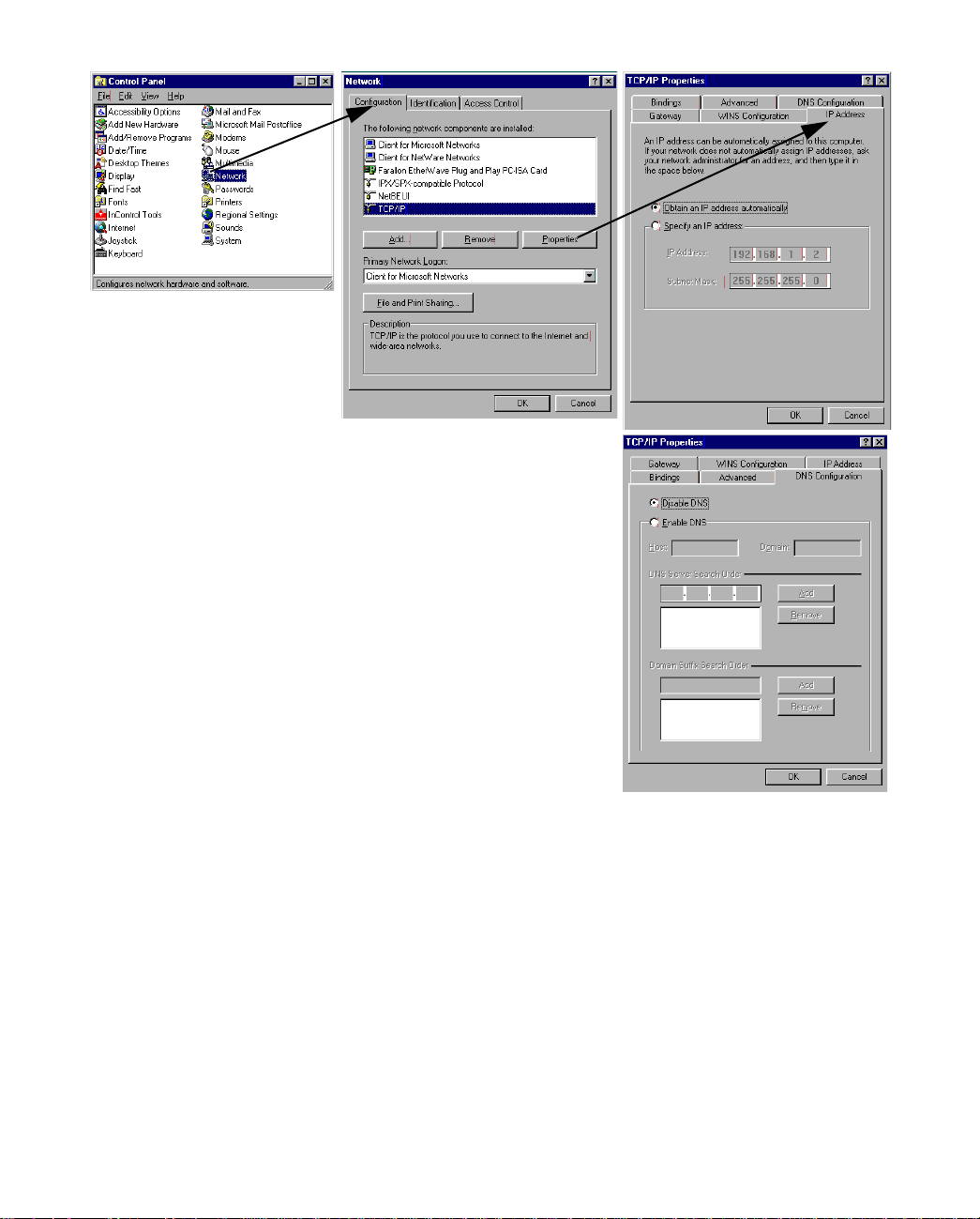
1. Go to the Start
Menu/Settings/Control
Panels and double click
the Network icon. From
the Network components
list, select the
Configuration tab.
2. Select TCP/IP-->Your Network Card. Then select
Properties. In the TCP/IP Properties screen (shown
below), select the IP Address tab. Click “Obtain an IP
Address automatically.”
3. Click on the DNS Configuration tab. Click Disable DNS.
DNS will be assigned by the router with DHCP.
4. Click OK in this window, and the next window. When
prompted, reboot the computer.
Note: Y ou can also use these instructions to configure other computers on your network to accept IP addresses
served by the Netopia R310.
Page 35

Setting up your Router with the SmartStart Wizard 3-11
Static configuration (optional)
If you are manually configuring for a fixed or static IP address, perform the following:
1. Go to Start Menu/Settings/Control Panels and double click the Network icon. From the Network
components list, select the Configuration tab.
2. Select TCP/IP-->Your Network Card. Then select Properties. In the TCP/IP Properties screen (shown
below), select the IP Address tab. Click “Specify an IP Address.”
Enter the following:
IP Address: 192.168.1.2
Subnet Mask: 255.255.255.0
This address is an example of one that can be used to configure the router with the Easy option in the
SmartStart Wizard. Your ISP or network administrator may ask you to use a different IP address and
subnet mask.
Page 36

3-12 User’s Reference Guide
3. Click on the Gateway tab (shown below).
Under “New gateway,” enter
192.168.1.1. Click Add. This is the
Click on the DNS Configuration tab. Click Enable DNS.
Enter the following
information:
Netopia R310’s pre-assigned IP address.
Host: Type the name
you want to give to
this computer.
Domain: Type your
domain name. If you
don't have a domain
name, type your ISP's
domain name; for
example,
netopia.com.
DNS Server Search
Order: Type the
primary DNS IP
address given to you
by your ISP. Click
Add. Repeat this process for the secondary DNS.
Domain Suffix Search Order: Enter the same domain
name you entered above.
4. Click OK in this window, and the next window. When prompted, reboot the computer.
Note: You can also use these instructions to configure other computers on your network with manual or static
IP addresses. Be sure each computer on your network has its own IP address.
Configuring TCP/IP on Macintosh computers
The following is a quick guide to configuring TCP/IP for MacOS computers. Configuring TCP/IP in a Macintosh
computer requires the following:
■ You must have either Open Transport or Classic Networking (MacTCP) installed.
Note: If you want to use the Dynamic Host Configuration Protocol (DHCP) server built into your Netopia
R310 to assign IP addresses to your Macintoshes, you must be running Open Transport, standard in
MacOS 8, and optional for MacOS 7.5 and above.
■ You must have built-in Ethernet or a third-party Ethernet card and its associated drivers installed in your
Macintosh.
Dynamic configuration (recommended)
If you configure your Netopia R310 using SmartStart, you can accept the dynamic IP address assigned by your
router. The Dynamic Host Configuration Protocol (DHCP), which enables dynamic addressing, is enabled by
default in the router. To configure your Macintosh computer for dynamic addressing do the following:
Page 37

Setting up your Router with the SmartStart Wizard 3-13
1. Go to the Apple menu. Select Control Panels and then
TCP/IP.
2. With the TCP/IP window open, go to the Edit menu and
select User Mode. Choose Basic and click OK.
3. In the TCP/IP window, select “Connect via: Ethernet” and
“Configure: Using DHCP Server.”
Note: Y ou can also use these instructions to configure other computers on your network to accept IP addresses
served by the Netopia R310.
Static configuration (optional)
If you are manually configuring the computer on your Local
Area Network for a fixed or static IP address, perform the
following:
1. Go to the Apple menu. Select Control Panels and then
TCP/IP or MacTCP.
2. With the TCP/IP window open, go to the Edit menu and
select User Mode. Choose Advanced and click OK.
Or, in the MacTCP window, select Ethernet and click the
More button.
Page 38

3-14 User’s Reference Guide
3. In the TCP/IP window or in the MacTCP/More window, select or type information into the fields as shown in
the following table.
Option: Select/Type:
Connect via: Ethernet
Configure: Manually
IP Address: 192.168.1.2
Subnet mask: 255.255.255.0, or for 12-user models, 255.255.255.240
Router address: 192.168.1.1
Name server
address:
Implicit Search
Path:
Enter the primary and secondary name server addresses given to
you by your ISP
Enter your domain name; if you do not have a domain name, enter
the domain name of your ISP
Starting domain
name:
4. Close the TCP/IP or MacTCP control panel and save the settings.
5. If you are using MacTCP, you must restart the computer. If you are using Open Transport, you do not need
to restart.
These are the only fields you need to modify in this screen.
Note: You can also use these instructions to configure other computers on your network with manual or static
IP addresses. Be sure each computer on your network has its own IP address.
DNS Proxy and Caching Behavior
Please note, DNS Proxying is a standard Netopia router feature. This feature operates transparently with no
configuration required.
If the Netopia R310's DNS is 0.0.0.0 the router serves itself as the DNS to DHCP client workstations that are
configured to acquire their IP addresses dynamically. If the router obtains a valid DNS supplied by the ISP, it
does one of two things:
■ either it forwards all DNS requests it receives to its DNS and remaps them when the response is received,
or
■ it constructs a DNS response if it finds the mapping in its own DNS cache.
This ensures that DHCP clients of the Netopia R310 will be able to use DNS as soon as the NetopiaR310 is
able to do so.
If the Netopia R310 is rebooted in a state wherein its DNS is non-zero, then the router will thereafter seed its
DHCP clients with the router’s DNS.
If for any reason you want to use the Netopia R310's DNS proxy feature all the time, then you manually
configure your client workstations’ IP stack so that your DNS is the Netopia R310.
Page 39

Connecting Your Local Area Network 4-1
CCCChhhhaaaapppptttteeeerrrr 44
CCCCoooonnnnnnnneeeeccccttttiiiinnnngggg YYYYoooouuuurrrr LLLLooooccccaaaallll AAAArrrreeeeaaaa NNNNeeeettttwwwwoooorrrrkk
This chapter describes how physically to connect the Netopia R310 ISDN Router to your local area network
(LAN). Before you proceed, make sure the Netopia R310 is properly configured. You can customize the Router’s
configuration for your particular LAN requirements using Console-based Management (see “Console-based
Management” on page 5-1).
This section covers the following topics:
■ “Readying computers on your local network” on page 4-1
■ “Connecting to an Ethernet network” on page 4-2
44
kk
Readying computers on your local network
PC and Macintosh computers must have certain components installed before they can communicate through
the Netopia R310. The following illustration shows the minimal requirements for a typical PC or Macintosh
computer.
Application software
TCP/IP stack
Ethernet Driver
Your PC
or Macintosh
computer
To the Netopia R310
Application software: This is the software you use to send e-mail, browse the World Wide Web, read
newsgroups, etc. These applications may require some configuration. Examples include the Eudora e-mail
client, and the web browsers Microsoft Internet Explorer and Netscape Navigator.
TCP/IP stack: This is the software that lets your PC or Macintosh communicate using Internet protocols.
TCP/IP stacks must be configured with some of the same information you used to configure the Netopia R310.
There are a number of TCP/IP stacks available for PC computers. Windows 95 includes a built-in TCP/IP stack.
See “Configuring TCP/IP on Windows 95, 98, or NT computers” on page 3-9. Macintosh computers use either
MacTCP or Open Transport. See “Configuring TCP/IP on Macintosh computers” on page 3-12.
Ethernet: Ethernet hardware and software drivers enable your PC or Macintosh computer to communicate on
the LAN.
Page 40

4-2 User’s Reference Guide
Once the Netopia R310 is properly configured and connected to your LAN, PC and Macintosh computers that
have their required components in place will be able to connect to the Internet or other remote IP networks.
Connecting to an Ethernet network
You can connect the Netopia R310 to an IP network that uses Ethernet. The Netopia R310 supports Ethernet
connections through its four Ethernet ports. The Router automatically detects which Ethernet port is in use.
You can connect a standard 10Base-T Ethernet network to the Netopia R310 using any of its available Ethernet
ports.
Netopia R310 back panel
Ethernet
4 3 2 1
4-port Ethernet hub Console port Power port
Uplink
The Netopia R310 in a 10Base-T network
Ethernet
34 12
Console
Line
Line port
Power
To connect your 10Base-T network to the Netopia R310 through an Ethernet port, use a 10Base-T cable with
RJ-45 connectors.
If you have more than four devices to connect, you can attach additional devices using a 10Base-T hub.
Page 41

Console-based Management 5-1
CCCChhhhaaaapppptttteeeerrrr 55
CCCCoooonnnnssssoooolllleeee----bbbbaaaasssseeeedddd MMMMaaaannnnaaaaggggeeeemmmmeeeennnntt
This chapter describes how to use the Console-based management screens on your Netopia R310 ISDN
Router. The console screens provide an alternate method for experienced users to configure their router
without using SmartStart. After completing the Easy Setup console screens, your router will be ready to connect
to the Internet or another remote site.
This chapter covers the following topics:
■ “About Console-based Management” on page 5-1
■ “Connecting through a Telnet session” on page 5-2
■ “Connecting a local terminal console cable to your router” on page 5-3
■ “Navigating through the console screens” on page 5-5
55
tt
About Console-based Management
Console-based management is a menu-driven interface for the capabilities built in to the Netopia R310.
Console-based management provides access to a wide variety of features that the router supports. You can
customize these features for your individual setup. This section describes how to access the console-based
management screens.
Console-based management screens contain seven entry points to the Netopia Router configuration and
monitoring features. The entry points are displayed in the Main Menu shown below:
Netopia R310 v4.6
Easy Setup...
WAN Configuration...
System Configuration...
Utilities & Diagnostics...
Statistics & Logs...
Quick Menus...
Quick View...
You always start from this main screen.
Page 42

5-2 User’s Reference Guide
Note about screen differences. Netopia R310 models offering different feature sets will have variations in the
fields on certain screens. For example, there are switched (dial-up ISDN) and leased (Synchronous/Asynchronous and T1) line models, as well as models that offer feature subsets such as SmartIP (Network Address
Translation and DHCP). Your own console screens may look different from those illustrated in this manual.
■ The Easy Setup menus display and permit changing the values contained in the default Connection Profile
you created when you ran the SmartStart Wizard for initial configuration. Experienced users can also use
Easy Setup to initially configure the router directly through a console session without using SmartStart.
Easy Setup menus contain up to five descendant screens for viewing or altering these values. The number
of screens depends on whether you have optional features installed.
■ The WAN Configuration menu displays and permits changing your Connection Profile(s), creating or
deleting additional Connection Profiles, and configuring or reconfiguring the manner in which you may be
using the router to connect to more than one service provider or remote site.
■ The System Configuration menus display and permit changing:
■ Network Protocols Setup. See “IP Setup and Network Address Translation” on page 9-1.
■ Filter Sets (Firewalls). See “Security” on page 12-1.
■ IP Address Serving. See “IP Setup and Network Address Translation” on page 9-1.
■ Date and Time. See “Date and Time” on page 7-13.
■ Console Configuration. See “Connecting a local terminal console cable to your router” on page 5-3.
■ SNMP (Simple Network Management Protocol). See “SNMP” on page 11-10.
■ Security. See “Security” on page 12-1.
■ Upgrade Feature Set. See “Upgrade Feature Set” on page 7-15.
■ Logging. See “Logging” on page 7-15.
■ The Utilities & Diagnostics menus provide a selection of seven tools for monitoring and diagnosing the
router's behavior, as well as updating the firmware and rebooting the system. See “Utilities and
Diagnostics” on page 13-1 for detailed information.
■ The Statistics & Logs menus display nine sets of tables and device logs that show information about your
router, your network and their history. See “Statistics & Logs” on page 11-4 for detailed information.
■ The Quick Menus screen is a shortcut entry point to many of the most commonly used configuration
menus that are accessed through the other menu entry points.
■ The Quick View menu displays at a glance current real-time operating information about your router. See
“Quick View status overview” on page 11-1 for detailed information.
Connecting through a Telnet session
Features of the Netopia R310 may be configured through the console screens.
Before you can access the console screens through Telnet, you must have:
■ a network connection locally to the router or IP access to the router through the WAN port. This could be
the same connection as the one you used with SmartStart and the "Easy" path. If you used the default
configuration for SmartStart, your IP address will be 192.168.1.1.
Page 43

Console-based Management 5-3
Note: Alternatively, you can have a direct serial console cable connection using the provided console cable
for your platform (PC or Macintosh) and the “Console” port on the back of the router. For more information
on attaching the console cable, see “Connecting a local terminal console cable to your router,” below.
■ Telnet software installed on the computer you will use to configure the router
Configuring Telnet software
If you are configuring your router using a Telnet session, your computer must be running a Telnet software
program.
■ If you connect a PC with Microsoft Windows, you can use a Windows Telnet application or simply run Telnet
from the Start menu.
■ If you connect a Macintosh computer, you can use the NCSA T elnet program supplied on the Netopia R310
CD. You install NCSA Telnet by simply dragging the application from the CD to your hard disk.
Connecting a local terminal console cable to your router
You can perform all of the System Configuration activities for your Netopia R310 through a local serial console
connection using terminal emulation software, such as HyperTerminal provided with Windows 95 or 98 on the
PC, or ZTerm, included on the Netopia CD, for the Macintosh.
The Netopia R310 back panel has a connector labeled “Console” for attaching the Router to either a PC or
Macintosh computer via the serial port on the computer. (On a Macintosh, the serial port is called the Modem
port or the Printer port.) This connection lets you use the computer to configure and monitor the Netopia R310
via the console screens.
Ethernet
4 3 2 1
Uplink
Console
Console port
Line
Power
T o connect the Netopia R310 to your computer for serial console communication, use the supplied dual console
cable connector end appropriate to your platform:
■ one DB-9 connector end attaches to a PC
■ the mini-DIN8 connector end attaches to a Macintosh
■ the DB-9 end of the Console cable attaches to the Netopia R310’s Console port
If you are configuring your router via a terminal session, your computer must be running a standard terminal
emulation or communications software program, such as those used with modems.
■ If you connect a PC with Microsoft Windows 95 or NT, you can use the HyperTerminal application bundled
Page 44

5-4 User’s Reference Guide
with the operating system.
■ If you connect a Macintosh computer, you can use the ZTerm terminal emulation program on the supplied
Netopia R310 CD.
Launch your terminal emulation software and configure the communications software for the following values.
These are the default communication parameters that the Netopia R310 uses.
Parameter Suggested Value
Terminal type PC: ANSI-BBS
Mac: ANSI, VT-100, or VT-200
Data bits 8
Parity None
Stop bits 1
Speed Options are: 9600, 19200, 38400, or 57600 bits per second
Flow Control None
Note: The router firmware contains an autobaud detection feature. If you are at
any screen on the serial console, you can change your baud rate and press
Return (HyperTerminal for the PC requires a disconnect). The new baud rate is
displayed at the bottom of the screen.
Page 45

Console-based Management 5-5
Navigating through the console screens
Use your keyboard to navigate the Netopia R310’s configuration screens, enter and edit information, and make
choices. The following table lists the keys to use to navigate through the console screens.
To... Use These Keys...
Move through selectable items in a screen or pop-up menu Up, Down, Left, and
Right Arrow
To set a change to a selected item or open a pop-up menu of
options for a selected item like entering an upgrade key
Change a toggle value (Yes/No, On/Off) Tab
Restore an entry or toggle value to its previous value Esc
Move one item up Up arrow or Control + k
Move one item down Down arrow or Control + j
Display a dump of the device event log Control + e
Display a dump of the WAN event log Control + f
Refresh the screen Control + L
Go to topmost selectable item <
Go to bottom right selectable item >
To help you find your way to particular screens, some sections in this guide begin with a graphical path guide
similar to the following example:
Main
Menu
System
Configuration
Network Protocols
Setup
Return or Enter
IP Setup
This particular path guide shows how to get to the Network Protocols Setup screens. The path guide represents
these steps:
1. Beginning in the Main Menu, select the System Configuration item and press Return.
2. Select the Network Protocols item in the System Configuration screen and press Return.
3. Select the IP Setup item in the Network Protocols Setup screen and press Return.
To go back in this sequence of screens, use the Escape key.
Page 46

5-6 User’s Reference Guide
Page 47

Easy Setup 6-1
CCCChhhhaaaapppptttteeeerrrr 66
EEEEaaaassssyyyy SSSSeeeettttuuuupp
This chapter describes how to use the Easy Setup console screens on your Netopia R310 ISDN Router. The
Easy Setup console screens provide an alternate method for experienced users to set up their router’s
Connection Profiles without using SmartStart. After completing the Easy Setup console screens, your router will
be ready to connect to the Internet or another remote site.
This chapter covers the following topics:
■ “Easy Setup console screens” on page 6-1
■ “Beginning Easy Setup” on page 6-3
66
pp
Easy Setup console screens
Using four Easy Setup console screens, you can:
■ set up your switch type and datalink parameters
■ create or modify a Connection Profile for your Router for the connection to your ISP or remote location
■ set up IP addresses and IP address serving
■ password protect configuration access to your Netopia R310 ISDN Router
How to access the Easy Setup console screens
To access the console screens, Telnet to the Netopia Router over your Ethernet network, or you can physically
connect with a serial console cable and access the Netopia Router with a terminal emulation program. See
“Connecting through a Telnet session” on page 5-2 or “Connecting a local terminal console cable to your
router” on page 5-3.
Note: Before continuing, make sure that you have the information that your telephone service provider, ISP, or
network administrator has given you to configure the Netopia Router.
The Netopia Router’s first console screen, Main Menu, appears in the terminal emulation window of the
attached PC or Macintosh when:
■ the Netopia Router is turned on
■ the computer is connected to the Netopia Router
■ the Telnet or terminal emulation software is running and configured correctly.
Page 48

6-2 User’s Reference Guide
A screen similar to the following appears:
Netopia R310 v4.6
Easy Setup...
WAN Configuration...
System Configuration...
Utilities & Diagnostics...
Statistics & Logs...
Quick Menus...
Quick View...
Return/Enter goes to Easy Setup -- minimal configuration.
You always start from this main screen.
If you do not see the Main Menu, verify that:
■ the computer used to view the console screen has its serial port connected to the Netopia R310’s
“Console” port or an Ethernet connection to one of its Ethernet ports. See “Connecting a local terminal
console cable to your router” on page 5-3 or “Connecting through a Telnet session” on page 5-2.
■ the Telnet or terminal emulation software is configured for the recommended values.
■ if you are connecting via the Console port, the console’s serial port is not being used by another device,
such as an internal modem, or an application. Turn off all other programs (other than your terminal
emulation program) that may be interfering with your access to the port.
■ you have entered the correct password, if necessary. Your Netopia R310’s console access may be
password protected from a previous configuration. See your system administrator to obtain the password.
See Appendix A, “Troubleshooting,” for more suggestions.
Page 49

Beginning Easy Setup
To begin Easy Setup, select Easy Setup in the Main Menu, then press Return.
The Easy Setup screen appears. EuroISDN/ETSI
ISDN Easy Setup
Circuit Type... ISDN, Switched
Switch Type... EuroISDN/ETSI Detected
Directory Number 1: 5088324614 Detected
Directory Number 2: 5088324615 Detected
PBX Prefix:
Data Link Encapsulation... PPP
TO MAIN MENU NEXT SCREEN
Return/Enter to select <among/between> ...
Enter information supplied to you by your ISDN phone company.
Easy Setup 6-3
ISDN Easy Setup
The Easy Setup Profile screen is where you configure the parameters that control the Netopia R310’s
connection to a specific remote destination, usually an ISP or a corporate site.
On a Netopia R310 ISDN Router you can add up to 15 more connection profiles, for a total of 16.
1. Select Circuit Type and press Return. From the pop-up menu, select:
ISDN, Switched if you have a switched ISDN line. This option covers the broadest range of applications and
defaults to Euro-ISDN, or
ISDN, Leased if you have a dedicated or leased (“nailed-up”) ISDN line that uses a single B channel (64K),
2B (128K), or the entire ISDN bandwidth of 2B+D (144K)
If you select ISDN, Leased as your circuit type, select Data Rate (kbps). From the pop-up menu, select the
appropriate B-channel, such as B1, B2, B1+B2, or 2B+D. Then skip to step 6.
It is possible to configure the router for any available circuit type: ISDN, Switched or ISDN, Leased
depending on the switch gear you are connected to.
If you create a connection profile using a particular datalink encapsulation method, that profile will take
precedence whenever you connect to a line that uses that datalink encapsulation. If there is no connection
profile with the datalink encapsulation method that the line uses, the router will default to using the default
profile. See “The Default Profile” on page 7-5 for more information.
Page 50

6-4 User’s Reference Guide
2. Select Switch Type and press Return. From the pop-up menu, select the switch protocol your ISDN service
provider uses.
For European countries other than the United Kingdom, use the EuroISDN/ETSI setting. United Kingdom
users select United Kingdom - EuroISDN.
3. Select Directory Number 1.
The router attempted to detect your Directory Number(s) when you selected Auto-Detect in Step 1.
If it succeeded, the directory number(s) will be displayed, and the screen will indicate “Detected” (as
shown on page 6-3).
If it failed to detect your directory numbers, the fields will remain blank, and you must enter the primary
directory number as you would dial it, including area code. Do not enter access prefixes such as Centrex or
PBX prefixes like “9” (for an outside line). Press Return.
4. If you have a second directory number, select Directory Number 2 and enter the secondary directory
number as you would dial it, including area code. Press Return.
5. If you require a dialing prefix such as “9” to access an outside line on a PBX or Centrex phone system,
select PBX Prefix and enter your dialing prefix. Press Return.
6. Select Data Link Encapsulation and highlight the method of encapsulation that you want to use from the
pop-up menu. The choices offered are PPP or HDLC. The default for switched interfaces is PPP. Press
Return.
7. Select NEXT SCREEN and press Return. The “Easy Setup Profile” screen (shown on page 6-5) appears.
Any changes you make to the ISDN configuration now or in the future will take effect immediately. You do not
have to restart the router.
Page 51

Easy Setup 6-5
Easy Setup Profile
The Easy Setup Connection Profile screen is where you configure the parameters that control the ISDN Netopia
Router’s connection to a specific remote destination, usually another network.
Connection Profile 1: Easy Setup Profile
Number to Dial:
Address Translation Enabled: Yes
Local WAN IP Address: 0.0.0.0
Remote IP Address: 127.0.0.2
Remote IP Mask: 255.0.0.0
PPP Authentication... PAP
Send User Name:
Send Password:
PREVIOUS SCREEN NEXT SCREEN
Enter the directory number for the remote network connection.
Enter basic information about your WAN connection with this screen.
1. Select Number to Dial and enter the ISDN telephone number you received from your ISP. This is the
number the Netopia R310 dials to reach your ISP. Enter the number as you would dial it, including any
required prefixes (such as area, access, and long-distance dialing codes).
If you selected ISDN or Leased as your router’s Circuit Type in the ISDN Easy Setup screen, Number to Dial
will not be an available option.
2. To enable address translation, toggle Address Translation Enabled to Yes. For more information on
Network Address Translation, see Chapter 9, “IP Setup and Network Address Translation.”
Then select the Local WAN IP Address field. The default address is 0.0.0.0, which allows for dynamic
addressing, your ISP assigning an address each time you connect. However, you may enter another
address if you want to use static addressing.
Note: When using HDLC datalink encapsulation and Network Address Translation, you must use a static
address.
3. If your ISP uses Numbered (Interface-based Routing), select Local WAN IP Address and enter the local
WAN address your ISP gave you.
When using numbered interfaces, the Netopia Router will use its local WAN IP address and subnet mask to
send packets to the remote router. Both routers have WAN IP addresses and subnet masks associated
with the connection.
If your ISP uses Unnumbered (System-based Routing), select Remote IP Address and enter the IP address
your ISP gave you. Then select Remote IP Mask and enter the IP subnet mask of the remote site you will
connect to.
Page 52

6-6 User’s Reference Guide
When using unnumbered interfaces, the Netopia Router will use either its local Ethernet IP address or its
NAT address (if so configured) and subnet mask to send packets to the remote router. Neither router has a
WAN IP address or subnet mask associated with this connection.
Note: If your ISP has not given you their IP or subnet mask addresses, then you may enter an IP address
such as 127.0.0.2, and an IP subnet mask such as 255.0.0.0. which are acceptable as defaults values,
and will typically be assigned at the time of connection.
4. For circuits with PPP enabled: Select the PPP Authentication pop-up menu and choose the type of
connection security your ISP told you to use (either None, PAP, CHAP, PAP-TOKEN, or CACHE-TOKEN). If
you choose PAP, CHAP, PAP-TOKEN, or CACHE-TOKEN, go to the next step. If your ISP does not use any of
these authentication methods, choose None and skip to the last step. When you create a connection
profile from Easy Setup, the default setting is PAP.
5. For circuits with PPP enabled: If your ISP uses PAP, select Send User Name and enter the user name your
ISP gave you to connect. Then select Send Password and enter the password.
If your ISP uses CHAP , select Send Host Name and enter the user name your ISP gave you to connect. Then
select Send Secret and enter the secret (CHAP term for password) your ISP gave you.
6. Select NEXT SCREEN and press Return. The IP Easy Setup screen appears.
Page 53

Easy Setup 6-7
IP Easy Setup
The IP Easy Setup screen is where you enter information about your Netopia Router’s:
■ IP address
■ Subnet mask
■ Default gateway IP address
■ Domain name server IP address
■ IP address serving information, such as the number of client IP addresses and the 1st client address; and
Y ou should consult with your network administrator to obtain the information you will need. For more information
about setting up IP, see “IP Setup and Network Address Translation” on page 9-1.
IP Easy Setup
Ethernet IP Address: 192.168.1.1
Ethernet Subnet Mask: 255.255.255.0
Domain Name:
Primary Domain Name Server: 192.168.1.10
Secondary Domain Name Server: 0.0.0.0
Default IP Gateway: 0.0.0.0
IP Address Serving: On
Number of Client IP Addresses: 100
1st Client Address: 192.168.1.3
PREVIOUS SCREEN NEXT SCREEN
Enter an IP address in decimal and dot form (xxx.xxx.xxx.xxx).
Set up the basic IP attributes of your Netopia in this screen.
1. Select Ethernet IP Address and enter the first IP address from the IP address range your ISP has given
you. This will be the Netopia Router’s IP address.
If Network Address Translation is enabled in the Easy Setup connection profile, the Ethernet IP Address
defaults to an address within a range reserved by the Internet address administration authority for use
within private networks, 192.168.1.1.
Because this is a private network address, it should never be directly connected to the Internet. Using NAT
for all your connection profiles will ensure this restriction. See “IP Setup and Network Address Translation”
on page 9-1 for more information.
2. Select Ethernet Subnet Mask and enter the subnet mask your ISP has given you. The Ethernet Subnet
Mask defaults to a standard class C mask, 255.255.255.0.
3. Select Domain Name and enter the domain name your ISP has given you.
4. Select Primary Domain Name Server and enter the IP address your ISP has given you.
Page 54

6-8 User’s Reference Guide
5. The Default IP Gateway defaults to the remote IP address you entered in the Easy Setup connection
profile. If the Netopia Router does not recognize the destination of any IP traffic, it forwards that traffic to
this gateway – set to 127.0.0.2 if your ISP does not otherwise specify.
Do not confuse the remote IP address and the default gateway’s IP address with the block of local IP
addresses you receive from your ISP. You use the local IP addresses for the Netopia R310’s Ethernet port
and for IP clients on your local network. The remote IP address and the default gateway’s IP address
should point to your ISP’s router.
6. To use DHCP address serving, toggle IP Address Serving to On.
7. If IP Address Serving is On, select Number of Client IP Addresses. Then enter the number of available
host addresses for the Netopia R310 ISDN Router to allocate to the client computers on your network. This
number defaults to the balance of the subnet addresses above the Netopia Router’s address.
8. If IP Address Serving is On, select 1st Client Address and enter the first IP address in the set of allocated
served IP addresses.
Note: On a Netopia R310 the factory default IP Address serving settings are:
1st Client Address: 192.168.1.3
Number of Client IP Addresses: unlimited models:100; limited models: number of users minus 1
(this allows for one static address at 192.168.1.2 for the server)
The values you set in this screen are displayed in the “Quick View status overview” on page 11-1.
9. Press Return. The Easy Setup Security Configuration screen appears.
Easy Setup Security
The Easy Setup Security Configuration screen lets you password-protect your Netopia R310. Input your Write
Access Name and Write Access Password with names or numbers totaling up to eleven digits.
If you password protect the console screens, you will be prompted to enter the name and password you have
specified every time you log in to the console screens. Do not forget your name and password. If you do, you
will be unable to access any of the configuration screens.
Additional security features are available. See Chapter 12, “Security.”
Page 55

Easy Setup 6-9
Easy Setup Security Configuration
It is strongly suggested that you password-protect configuration access to your
Netopia. By entering a Name and Password pair here, access via serial, PC Card,
Telnet, SNMP and Web Server will be password-protected.
Be sure to remember what you have typed here, because you will be prompted for
it each time you configure this Netopia.
Write Access Name:
Write Access Password:
PREVIOUS SCREEN TO MAIN MENU RESTART DEVICE
Configure a Configuration Access Name and Password here.
The final step in configuring the Easy Setup console screens is to restart the Netopia R310, so the
configuration settings take effect.
1. Select RESTART DEVICE. A prompt asks you to confirm your choice.
2. Select CONTINUE to restart the Netopia Router and have your selections take effect.
Note: You can also restart the system at any time by using the restart utility (see “Restarting the system” on
page 13-12) or by turning the Netopia Router off and on with the power switch.
Easy Setup is now complete.
Page 56

6-10 User’s Reference Guide
Page 57

PPPPaaaarrrrtttt IIIIIIII:::: AAAAddddvvvvaaaannnncccceeeedddd CCCCoooonnnnffffiiiigggguuuurrrraaaattttiiiioooonn
nn
Page 58

User’s Reference Guide
Page 59

WAN and System Configuration 7-1
CCCChhhhaaaapppptttteeeerrrr 77
WWWWAAAANNNN aaaannnndddd SSSSyyyysssstttteeeemmmm CCCCoooonnnnffffiiiigggguuuurrrraaaattttiiiioooonn
This chapter describes how to use the console-based management screens to access and configure advanced
features of your Netopia R310 ISDN Router. You can customize these features for your individual setup. These
menus provide a powerful method for experienced users to set up their router’s connection profiles and system
configuration.
This section covers the following topics:
■ “Creating a new Connection Profile” on page 7-1
■ “The Default Profile” on page 7-5
■ “The Default Profile” on page 7-5
■ “System Configuration screens” on page 7-10
■ “System Configuration features” on page 7-11
77
nn
Creating a new Connection Profile
Connection Profiles define the telephone and networking protocols necessary for the router to make a remote
connection. A Connection Profile is like an address book entry describing how the router is to get to a remote
site, or how to recognize and authenticate a remote user dialing in to the router. For example, to create a new
Connection Profile, you navigate to the WAN Configuration screen from the Main Menu, and select Add
Connection Profile.
Main
Menu
WAN
Configuration
Add Connection
Profile
Page 60

7-2 User’s Reference Guide
The Add Connection Profile screen appears.
Add Connection Profile
Profile Name: Profile 02
Profile Enabled: Yes
IP Enabled: Yes
IP Profile Parameters...
Data Link Encapsulation... PPP
Data Link Options...
Telco Options...
ADD PROFILE NOW CANCEL
Return accepts * ESC cancels * Left/Right moves insertion point * Del deletes.
Configure a new Conn. Profile. Finished? ADD or CANCEL to exit.
On a Netopia R310 ISDN Router you can add up to 15 more connection profiles, for a total of 16.
1. Select Profile Name and enter a name for this connection profile. It can be any name you wish. For
example: the name of your ISP.
2. Toggle the Profile Enabled value to Yes or No. The default is Yes.
3. Select IP Profile Parameters and press Return. The IP Profile Parameters screen appears.
IP Profile Parameters
Address Translation Enabled: Yes
Local WAN IP Address: 0.0.0.0
Remote IP Address: 0.0.0.0
Remote IP Mask: 0.0.0.0
Filter Set...
Remove Filter Set
Receive RIP: Off
Toggle to Yes if this is a single IP address ISP account.
Configure IP requirements for a remote network connection here.
Page 61

WAN and System Configuration 7-3
4. Toggle or enter any IP Parameters you require and return to the Add Connection Profile screen by pressing
Escape. For more information, see “IP Setup and Network Address Translation” on page 9-1.
5. Select Datalink Options and press Return. The Datalink Options screen appears.
Datalink (PPP/MP) Options
Data Compression... Ascend LZS
Send Authentication... PAP
Send User Name:
Send Password:
Receive User Name:
Receive Password:
Channel Usage... Dynamic
Bandwidth Allocation... BAP
Maximum Packet Size: 1500
In this Screen you will configure the PPP/MP specific connection params.
You can accept the defaults, or change them if you wish. Y ou can also specify user name and password for
both outgoing and incoming calls. the Send User Name/Password parameters are used to specify your
identity when dialing out to a remote location. The Receive User Name/Password parameters are used
when receiving dial-in clients such as via RAS configuration.
The Channel Usage pop-up menu allows you to choose how many lines your connections may use, and
whether or not they are preemptable. Supported options are:
Option Behavior
Dynamic 1 to 3 channels, if available, will be used, depending on traffic volume
1-Channel Only 1 channel will be used
2-Channels 2 channels will be preferred
2-Channel Preemptable 2 channels will be used, but 1 may be reallocated
Note: The Bandwidth Allocation pop-up options are: Off, Auto, BAP or MP+. BAP is the default. You should
only choose one of the other options if you are specifically advised to do so by your ISP or administrator.
Return to the Add Connection Profile screen by pressing Escape.
Page 62

7-4 User’s Reference Guide
6. Select Telco Options and press return. the Telco Options screen appears.
Telco Options
Initiate Data Service... 64 kb/sec
Dial... Dial In/Out
Number to Dial:
Alternate Site to Dial:
Dial on Demand: Yes
Idle Timeout (seconds): 300
CNA Validation Number:
Callback: No
Maximum connect time (HH:MM): 0:00
Return/Enter to select data rate/class of service.
In this Screen you configure options for the ways you will establish a link.
Select Dial and press Return. A pop-up menu appears. You can select the dialing options for this
Connection Profile as Dial In Only, Dial Out Only, or Dial In/Out.
You can:
■ select a type of data service to initiate, 64 kb/sec (the default), 56 kb/sec, or Speech
■ add the number to dial for this Connection Profile
■ add an alternate number
■ change any of the default parameter settings
■ if you have enabled Call Accounting (see “Cost control feature -- call accounting” on page 8-1) you can
set the Maximum connect time for this connection profile by entering the hours and minutes in
HH:MM format. When aggregate usage for this profile reaches this threshold, the profile becomes temporarily disabled until the limit is raised or the counters are reset (see “Viewing call accounting statis-
tics” on page 8-2). If Call Accounting is not enabled, this field does not appear.
When you are finished with these entries, press Escape to return to the Add Connection Profile screen.
7. Select ADD PROFILE NOW and press Return. Your new Connection Profile will be added.
Page 63

WAN and System Configuration 7-5
If you want to view the Connection Profiles in your router, return to the WAN Configuration screen, and
select Display/Change Connection Profile. The list of Connection Profiles is displayed in a scrolling pop-up
screen.
WAN Configuration
+-Profile Name---------------------IP Address----------------+
+------------------------------------------------------------+
| SmartStart Profile 127.0.0.2 |
| Profile 02 0.0.0.0 |
| |
| |
| |
| |
| |
| |
| |
| |
| |
| |
| |
| |
| |
| |
+------------------------------------------------------------+
Up/Down Arrow Keys to select, ESC to dismiss, Return/Enter to Edit.
It is possible to configure the router for any available circuit type: ISDN, Switched or ISDN, Leased, depending
on the switch gear you are connected to.
If you create a Connection Profile using a particular datalink encapsulation method, that profile will take
precedence whenever you connect to a line that uses that datalink encapsulation. If there is no Connection
Profile with the datalink encapsulation method that the line uses, the router will default to using the Default
Profile. See “The Default Profile,” for more information.
The Default Profile
How the default profile works
The default profile works like a guard booth at the gate to your network: it scrutinizes WAN connections. Like the
guard booth, the default profile allows connections based on a set of criteria that you define.
The main criterion used to check connections is whether they match one of the connection profiles already
defined. A connection is matched to a connection profile using the remote network’s IP address (that is, the
caller is defined as the destination of a particular connection profile).
If a connection matches an existing profile, all of the connection profile parameters are adopted for the call.
When using PPP or Cisco-HDLC datalink encapsulation on a permanent circuit, you must configure a connection
profile. Note, that you may have already configured this connection profile in Easy Setup.
See “Easy Setup” on page 6-1 for information on configuring an Easy Setup connection profile.
Page 64

7-6 User’s Reference Guide
Customizing the Default Profile
The Default Profile screen controls whether or not an ISDN link will come up without an explicitly configured
connection profile. See “Creating a new Connection Profile” on page 7-1 for more information. You access the
Default Profile screen from the Main Menu by selecting WAN Configuration and then selecting Default Profile.
Main
Menu
WAN
Configuration
Default
Profile
The Default Profile screen appears.
Default Profile
Must Match a Defined Profile: Yes
IP Enabled: Yes
IP Parameters...
■ You can set Must Match a Defined Profile item to Yes or No (the default). This item controls whether or
not the ISDN link will come up without an explicitly configured connection profile. If your ISP is serving you
a dynamic IP Address, you need not explicitly configure a connection profile, and the default behavior of the
router will be to connect automatically once it is powered on.
■ If Must Match a Defined Profile is set to No, then an IP Enabled item is visible. Toggling this item to Yes
(the default) or No controls whether or not IP will be supported on the ISDN link. If IP Enabled is set to Y es,
an IP Parameters item becomes visible. If you select IP Parameters the IP Parameters screen appears
(see “IP parameters (default profile) screen” on page 7-7). This screen allows you to configure various IP
parameters for ISDN connections established without an explicitly configured connection profile.
Page 65

WAN and System Configuration 7-7
IP parameters (default profile) screen
The IP Parameters (Default Profile) screen allows you to configure various IP parameters for ISDN connections
established without an explicitly configured connection profile:
IP Parameters (Default Profile)
Default Subnet Mask: 0.0.0.0
Filter Set (Firewall)...
Remove Filter Set
Receive RIP: Both
Transmit RIP: v2 (multicast)
The Netopia R310 ISDN Router always acts as a DHCP client on the ISDN link when using a Default Profile. The
DHCP server will supply a local IP address and subnet mask. For an ISDN link, Network Address Translation
(NAT) is enabled by default in the Default Profile and the Default Subnet Mask is set to 0.0.0.0. For details on
setting up IP Parameters see “IP Setup and Network Address Translation” on page 9-1.
Routing Information Protocol (RIP) is needed if there are IP routers on other segments of your Ethernet network
that the Netopia R310 needs to recognize. Set to “Both” (the default) the Netopia R310 will accept information
from either RIP v1 or v2 routers. Alternatively, select Receive RIP and select v1 or v2 from the popup menu.
With Receive RIP set to “v1,” the Netopia R310’s Ethernet port will accept routing information provided by RIP
packets from other routers that use the same subnet mask. Set to “v2,” the Netopia R310 will accept routing
information provided by RIP packets from other routers that use different subnet masks.
If you want the Netopia R310 to advertise its routing table to other routers via RIP, select Transmit RIP and
select v1, v2 (broadcast), or v2 (multicast) from the popup menu. With Transmit RIP v1 selected, the Netopia
R310 will generate RIP packets only to other RIP v1 routers. With Transmit RIP v2 (broadcast) selected, the
Netopia R310 will generate RIP packets to all other hosts on the network. With Transmit RIP v2 (multicast)
selected, the Netopia R310 will generate RIP packets only to other routers capable of recognizing RIP v2
packets.
Page 66

7-8 User’s Reference Guide
IP Parameters (Default Profile)
Default Subnet Mask: 0.0.0.0
Filter Set (Firewall)...
Remove Filter Set
Receive RIP: +------------------+
Transmit RIP: +------------------+
TX RIP Policy... | Poison Reverse |
| Split Horizon |
| No Split Horizon |
+------------------+
If you choose to transmit RIP, the TX RIP Policy pop up menu appears. You can select Poison Reverse (the
default), Split Horizon, or No Split Horizon.
■ Poison Reverse speeds convergence but adds to network overhead. When topology changes, mentioning
routes that should not go through the router as well as those that should can speed up convergence.
■ If you select Split Horizon (“without Poison Reverse” is implied), the router omits routes learned from an
interface from RIP updates sent on that interface. Split Horizon without Poison Reverse has the advantage
of minimizing network overhead in large network configurations at the expense of slower convergence.
■ No Split Horizon is suitable for partially meshed networks. A partially meshed network is a WAN in which
one or more nodes do not have logically direct connections to all other nodes. In a star or partially meshed
topology, you may need to disable Split Horizon so the routers can learn about other networks.
Delayed Remote Configuration Change Toggle
The Netopia R310 supports delaying some configuration changes until after the router is restarted.
If your router is preconfigured by your service provider, or if you are not remotely configuring the router, you can
leave this setting unchanged.
The purpose of this feature is to defer configuration changes only when remotely configuring or reconfiguring the
router to prevent premature console disconnection. When this feature is enabled, no changes to the WAN
setup, datalink encapsulation, Connection Profiles, DLCIs, or Default Gateways will take effect until after the
router is restarted. Until the router is restarted the WAN link and the routing table remain unaffected.
A single setting in the Choose Interface to Configure screen controls this feature, as shown below.
Main
Menu
WAN Configuration
Setup to Configure
Choose InterfaceWAN
Page 67

WAN and System Configuration 7-9
Choose Interface to Configure
Configuration Changes Reset WAN Connection: Yes
When you toggle Configuration Changes Reset WAN Connection using the Tab key and press Return, a pop-up
window asks you to confirm your choice.
Choose Interface to Configure
+----------------------------------------------------+
+----------------------------------------------------+
| The Router must be restarted to allow this feature |
| to function properly. |
| Are you sure you want to do this? |
| |
| CANCEL CONTINUE |
| |
+----------------------------------------------------+
Toggling from Yes to No makes the router ready to be configured. If you toggle from No to Yes, and confirm the
reboot, your changes are committed and the router comes up using the newly created configuration.
Page 68

7-10 User’s Reference Guide
System Configuration screens
ISDN Line Configuration
Circuit Type... ISDN, Switched
Switch Type... AT&T 5ESS Pt-to-Pt
Directory Number 1: 555-1234
PBX Prefix:
Data Link Encapsulation... PPP
Data Rate (kbps)... 38.4
Return/Enter to select <among/between> ...
Enter information supplied to you by your ISDN phone company.
You can connect to the Netopia R310’s System Configuration screens:
■ Using Telnet with the Router’s Ethernet port IP address
■ Through the console port, using a local terminal (see “Connecting a local terminal console cable to your
router” on page 5-3)
You can also retrieve the Netopia R310’s configuration information and remotely set its parameters using the
Simple Network Management Protocol (see “SNMP” on page 11-10).
Open a Telnet connection to the IP address you set in the router with SmartStart, for example “192.168.1.1.”
Page 69

WAN and System Configuration 7-11
The console screen will open to the Main Menu, similar to the screen shown below:
Netopia R310 v4.6
Easy Setup...
WAN Configuration...
System Configuration...
Utilities & Diagnostics...
Statistics & Logs...
Quick Menus...
Quick View...
Return/Enter goes to Easy Setup -- minimal configuration.
You always start from this main screen.
System Configuration features
SmartStart may be all you need to configure your Netopia R310. Some users, however, require advanced
settings or prefer manual control over the default selections that SmartStart automatically chooses. For these
users, the Netopia R310 provides System Configuration options.
To help you determine whether you need to use the System Configuration options, review the following
requirements. If you have one or more of these needs, use the System Configuration options described in the
later chapters.
■ Two or more outgoing connection profiles to connect to more than one remote location (for example, to
connect to the Internet and to a network at another office).
■ System Configuration of dynamic IP address distribution through DHCP, MacIP, or BootP.
■ Customized incoming call profile to control received calls.
■ Scheduled connections.
■ Greater network security through the use of filters, CallerID, callback, and SecurID.
■ System Configuration of connection profiles. See the table below for a partial list of the options available
through System Configuration.
Page 70

7-12 User’s Reference Guide
Layer Category Parameter Type Options Default settings
Protocol Layer IP Parameters Filter Sets: Basic Firewall
Datalink Layer PPP/MP Parameters Data Compression: Ascend LZS
Physical Layer Telco Parameters Dial is set to: Dial In/Out
RIP Receive/Transmit options: Off
Send Authentication: PAP
Channel Usage: Dynamic
Bandwidth Allocation: BAP
Maximum Packet Size: 1500
Dial On Demand is set to: Yes
Callback is set to: No
Idle Time-out is set for: 300 seconds
To access the System Configuration screens, select System Configuration in the Main Menu, then press
Return.
The System Configuration screen appears:
System Configuration
Network Protocols Setup...
Filter Sets (Firewalls)...
IP Address Serving...
Date and Time...
Console Configuration...
SNMP (Simple Network Management Protocol)...
Security...
Upgrade Feature Set...
Telephone Setup...
Logging...
Return/Enter to configure Networking Protocols (such as TCP/IP).
Use this screen if you want options beyond Easy Setup.
Page 71

WAN and System Configuration 7-13
Network Protocols Setup
These screens allow you to configure your network’s use of IP.
■ Details are given in “IP Setup and Network Address Translation” on page 9-1.
Filter Sets (Firewalls)
These screens allow you to configure security on your network by means of filter sets and a basic firewall.
■ Details are given in “Security” on page 12-1.
IP Address Serving
These screens allow you to configure IP Address serving on your network by means of DHCP, WANIP , and BootP.
■ Details are given in “IP Setup and Network Address Translation” on page 9-1.
Date and Time
You can set the system’s date and time in the Set Date and Time screen.
Select Date and Time in the System Configuration screen and press Return to go to the Set Date and Time
screen.
Set Date and Time
System Date Format: MM/DD/YY
Current Date (MM/DD/YY): 3/16/1998
System Time Format: AM/PM
Current Time: 10:29
AM or PM: AM
Follow these steps to set the system’s date and time:
1. Select Current Date and enter the date in the appropriate format. Use one- or two-digit numbers for the
month and day, and the last two digits of the current year. The date’s numbers must be separated by
forward slashes (/).
2. Select Current Time and enter the time in the format HH:MM, where HH is the hour (using either the
12-hour or 24-hour clock) and MM is the minutes.
Page 72

7-14 User’s Reference Guide
3. Select AM or PM and choose AM or PM.
Console Configuration
You can change the default terminal communications parameters to suit your requirements.
To go to the Console Configuration screen, select Console Configuration in the System Configuration screen.
Console Configuration
Baud Rate... 9600
Hardware Flow Control: No
SET CONFIG NOW CANCEL
Follow these steps to change a parameter’s value:
1. Select the parameter you want to change.
2. Select a new value for the parameter. Return to step 1 if you want to configure another parameter.
3. Select SET CONFIG NOW to save the new parameter settings. Select CANCEL to leave the parameters
unchanged and exit the Console Configuration screen.
Page 73

WAN and System Configuration 7-15
SNMP (Simple Network Management Protocol)
These screens allow you to monitor and configure your network by means of a standard Simple Network
Management Protocol (SNMP) agent.
■ Details are given in “SNMP” on page 11-10.
Security
These screens allow you to add users and define passwords on your network.
■ Details are given in “Security” on page 12-1.
Upgrade Feature Set
You can upgrade your Netopia R310 by adding new feature sets through the Upgrade Feature Set utility.
Vvisit the Netopia Web site at www.netopia.com for information on new feature sets, how to obtain them, and
how to install them on your Netopia R310.
Logging
You can configure a UNIX-compatible syslog client to report a number of subsets of the events entered in the
router’s WAN Event History. See “WAN Event History” on page 11-6.
Select Logging from the System Configuration menu.
The Logging Configuration screen appears.
Logging Configuration
WAN Event Log Options
Log Boot and Errors: Yes
Log Line Specific: Yes
Log Connections: Yes
Log PPP, DHCP, CNA: Yes
Log IP: Yes
Syslog Parameters
Syslog Enabled: No
Hostname or IP Address:
Facility... Local 0
Return/Enter accepts * Tab toggles * ESC cancels.
Page 74

7-16 User’s Reference Guide
By default, all events are logged in the event history.
■ By toggling each event descriptor either Yes or No, you can determine which ones are logged and which are
ignored.
■ You can enable or disable the syslog client dynamically. When enabled, it will report any appropriate and
previously unreported events.
■ You can specify the syslog server’s address either in dotted decimal format or as a DNS name up to 63
characters.
■ You can specify the UNIX syslog Facility to use by selecting the Facility pop-up.
The following screen shows a sample syslog dump of WAN events:
Nov 5 10:14:06 tsnext.netopia.com Link 1 down: PPP PAP failure
Nov 5 10:14:06 tsnext.netopia.com >>Issued Speech Setup Request from our DN: 5108645534
Nov 5 10:14:06 tsnext.netopia.com Requested Disc. from DN: 917143652500
Nov 5 10:14:06 tsnext.netopia.com Received Clear Confirm for our DN: 5108645534
Nov 5 10:14:06 tsnext.netopia.com Link 1 down: Manual disconnect
Nov 5 10:14:06 tsnext.netopia.com >>Issued Speech Setup Request from our DN: 5108645534
Nov 5 10:14:06 tsnext.netopia.com Requested Disc. from DN: 917143652500
Nov 5 10:14:06 tsnext.netopia.com Received Clear Confirm for our DN: 5108645534
Nov 5 10:14:06 tsnext.netopia.com Link 1 down: No answer
Nov 5 10:14:06 tsnext.netopia.com --Device restarted----------------------------------------Nov 5 10:14:06 tsnext.netopia.com >>Received Speech Setup Ind. from DN: (not supplied)
Nov 5 10:14:06 tsnext.netopia.com Requested Connect to our DN: 5108645534
Nov 5 10:14:06 tsnext.netopia.com ASYNC: Modem carrier detected (more) Modem reports: 26400
V34
Nov 5 10:14:06 tsnext.netopia.com >>WAN: 56K Modem 1 activated at 115 Kbps
Nov 5 10:14:06 tsnext.netopia.com Connect Confirmed to our DN: 5108645534
Nov 5 10:14:06 tsnext.netopia.com PPP: Channel 1 up, Answer Profile name: Default Profile
Nov 5 10:14:06 tsnext.netopia.com PPP: NCP up, session 1, Channel 1 Final (fallback)
negotiated auth: Local PAP , Remote NONE
Nov 5 10:14:06 tsnext.netopia.com PPP: PAP we accepted remote, Channel 1 Remote name: guest
Nov 5 10:14:06 tsnext.netopia.com PPP: MP negotiated, session 1 Remote EDO: 06 03
0000C5700624 0
Nov 5 10:14:06 tsnext.netopia.com PPP: CCP negotiated, session 1, type: Ascend LZS Local
mode: 1, Remote mode: 1
Nov 5 10:14:06 tsnext.netopia.com PPP: BACP negotiated, session 1 Local MN: FFFFFFFF, Remote
MN: 00000001
Nov 5 10:14:06 tsnext.netopia.com PPP: IPCP negotiated, session 1, rem: 192.168.10.100 local:
192.168.1.1
Nov 5 10:14:06 tsnext.netopia.com >>WAN: 56K Modem 1 deactivated
Nov 5 10:14:06 tsnext.netopia.com Received Clear Ind. from DN: 5108645534, Cause: 0
Nov 5 10:14:06 tsnext.netopia.com Issued Clear Response to DN: 5108645534
Nov 5 10:14:06 tsnext.netopia.com Link 1 down: Remote clearing
Nov 5 10:14:06 tsnext.netopia.com PPP: IPCP down, session 1
Nov 5 10:14:06 tsnext.netopia.com >>Received Speech Setup Ind. from DN: (not supplied)
Page 75

Call Accounting and Default Answer Profile 8-1
CCCChhhhaaaapppptttteeeerrrr 88
CCCCaaaallllllll AAAAccccccccoooouuuunnnnttttiiiinnnngggg aaaannnndddd DDDDeeeeffffaaaauuuulllltttt AAAAnnnnsssswwwweeeerrrr PPPPrrrrooooffffiiiillllee
You can set a Netopia Router to make scheduled connections using designated connection profiles. This is
useful for creating and controlling regularly scheduled periods when the router can be used by hosts on your
network. It is also useful for once-only connections that you want to schedule in advance.
The Netopia R310 ISDN Router can also answer calls as well as initiate them. To answer calls, the Netopia
R310 uses a Default Answer Profile. The Default Answer Profile controls how incoming calls are set up,
authenticated, filtered, and more.
Topics in this chapter include:
■ “Cost control feature -- call accounting” on page 8-1
■ “Scheduled connections” on page 8-4
■ “Default Answer Profile” on page 8-9
88
ee
Cost control feature -- call accounting
The Netopia R310 offers system-wide and per connection profile call accounting to track first minutes (an ISDN
tariff factor) and additional minutes, for initiated data and voice calls.
Main
Menu
To go to the Call Accounting screen, select Call Accounting Configuration in the WAN Configuration screen.
WAN
Configuration
Call Accounting
Configuration
Page 76

8-2 User’s Reference Guide
Call Accounting Configuration
Enable Call Accounting: On
Day for auto-reset of timers: 12
Maximum Aggregate connect time: 12:00
To enable call accounting, follow these steps:
1. Select Enable Call Accounting and toggle it to On.
2. Select Day for auto-reset of timers and enter the day of the month for the Router to reset the Call Account-
ing Statistics.
3. Select Maximum Aggregate connect time (HH:MM) and enter the total amount of time to allow for outbound calls, where HH is the hour (using either the 12-hour or 24-hour clock) and MM is the minutes.
Viewing call accounting statistics
To view call accounting statistics, go to the Statistics & Logs screen from the Main Menu and select Call
Accounting Statistics.
Main
Menu
Statistics &
Logs
Call Accounting
Statistics
Page 77

Call Accounting and Default Answer Profile 8-3
The Call Accounting Statistics screen appears.
Call Accounting Statistics
Aggregate Statistics...
Profile Statistics...
If you select Aggregate Statistics, the following screen appears.
Call Accounting Aggregate Statistics
Total First Minutes: 0
Total Additional Time (HH:MM): 0:00
Remaining Time (HH:MM): 12:00
RESET AGGREGATE MINUTE COUNTERS
Hit Return or Enter to reset Total First/Additional Time.
■ Total First Minutes displays the total number of first minutes of outbound calls placed during the recording
interval.
■ Total Additional Minutes (HH:MM) displays the total remaining time of all outbound calls placed during the
recording interval.
■ Remaining Time (HH:MM) displays how much time is left in the recording interval. If call accounting is not
enabled, the message will read, Call Accounting Disabled.
Page 78

8-4 User’s Reference Guide
■ You can reset the counters by selecting RESET AGGREGATE MINUTE COUNTERS. A dialog box will ask you
to confirm the reset. Select CONTINUE to reset the counters or CANCEL to leave them as is.
If you select Profile Statistics, the following screen appears.
Call Accounting Profile Statistics (in HHHH:MM)
Profile Name---------First Minutes----Additional Minutes-------Cutoff--Expired
----------------------------------SCROLL UP---------------------------------- Easy Setup Profile 0:00 0:00 0:00
---------------------------------SCROLL DOWN----------------------------------
You can view the individual usage statistics for each of the Connection Profiles you have defined.
Scheduled connections
To go to the Scheduled Connections screen, select Scheduled Connections in the WAN Configuration screen.
Main
Menu
WAN
Configuration
Scheduled
Connections
Page 79

Call Accounting and Default Answer Profile 8-5
Scheduled Connections
Display/Change Scheduled Connection...
Add Scheduled Connection...
Delete Scheduled Connection...
Navigate from here to add/modify/change/delete Scheduled Connections.
Viewing scheduled connections
To display a table of view-only scheduled connections, select Display/Change Scheduled Connection in the
Scheduled Connections screen. Each scheduled connection occupies one row of the table.
Scheduled Connections
+-Days----Begin At---HH:MM---When----Conn. Prof. Name----Enabled-----+
+--------------------------------------------------------------------+
| mtWtfss 08:30PM 06:00 weekly Profile 01 No |
| |
| |
| |
| |
| |
+--------------------------------------------------------------------+
The first column in the table shows a one-letter representation of the Days of the week, from Monday (M or m)
to Sunday (S or s). If a letter representing a day is capitalized, the connection will be activated on that day; a
lower-case letter means that the connection will not be activated on that day. If the scheduled connection is
configured for a once-only connection, the word “once” will appear instead of the days of the week.
Page 80

8-6 User’s Reference Guide
The other columns show:
■ The time of day that the connection will Begin At
■ The duration of the connection (HH:MM)
■ Whether it’s a recurring Weekly connection or used Once Only
■ Which connection profile (Conn. Prof.) is used to connect
■ Whether the scheduled connection is currently Enabled
The router checks the date and time set in scheduled connections against the system date and time.
Adding a scheduled connection
To add a new scheduled connection, select Add Scheduled Connection in the Scheduled Connections screen
and press Return. The Add Scheduled Connection screen appears.
Add Scheduled Connection
Scheduled Connection Enable: On
How Often... Weekly
Schedule Type... Forced
Set Weekly Schedule...
Use Connection Profile...
ADD SCHEDULED CONNECTION CANCEL
Scheduled Connections dial remote Networks on a Weekly or Once-Only basis.
Follow these steps to configure the new scheduled connection:
■ To activate the connection, select Scheduled Connection Enable and toggle it to On. You can make the
scheduled connection inactive by toggling Scheduled Connection Enable to Off.
■ Decide how often the connection should take place by selecting How Often and choosing Weekly or Once
Only from the pop-up menu.
■ The Schedule Type allows you to set the exact weekly schedule or once-only schedule.
Options are:
■ Forced Up, meaning that this connection will be maintained whether or not there is a demand call on
the line.
■ Forced Down, meaning that this connection will be torn down or blocked whether or not there is a
demand call on the line.
Page 81

Call Accounting and Default Answer Profile 8-7
■ Demand-Allowed, meaning that this schedule will permit a demand call on the line.
■ Demand-Blocked, meaning that this schedule will prevent a demand call on the line.
■ Periodic, meaning that the connection is retried several times during the scheduled time.
■ If How Often is set to Weekly, the item directly below How Often reads Set Weekly Schedule. If How Often
is set to Once Only, the item directly below How Often reads Set Once-Only Schedule.
Set Weekly Schedule
If you set How Often to Weekly, select Set Weekly Schedule and go to the Set Weekly Schedule screen.
■ Select the days for the scheduled connection to occur and toggle them to Yes.
Set Weekly Schedule
Monday: No
Tuesday: No
Wednesday: No
Thursday: No
Friday: No
Saturday: No
Sunday: No
Scheduled Window Start Time: 11:50
AM or PM: AM
Scheduled Window Duration Per Day: 00:00
■ Select Scheduled Window Start Time and enter the time to initiate the scheduled connection.
■ You must enter the time in the format H:M, where H is a one- or two-digit number representing the hour and
M is a one- or two-digit number representing the minutes. The colon is mandatory. For example, the entry
1:3 (or 1:03) would be accepted as 3 minutes after one o’clock. The entry 7:0 (or 7:00) would be accepted
as seven o’clock, exactly. The entries 44, :5, and 2: would be rejected.
■ Select AM or PM and choose AM or PM from the pop-up menu.
■ Select Scheduled Window Duration Per Day and enter the maximum duration allowed for this scheduled
connection, per call.
You are finished configuring the weekly options. Return to the Add Scheduled Connection screen to
continue.
Page 82

8-8 User’s Reference Guide
Set Once-Only Schedule
If you set How Often to Once Only, select Set Once-Only Schedule and go to the Set Once-Only Schedule
screen.
Set Once-Only Schedule
Place Call on (MM/DD/YY): 05/07/1998
Scheduled Window Start Time: 11:50
AM or PM: AM
Scheduled Window Duration: 00:00
■ Select Place Call On (Date) and enter a date in the format MM/DD/YY or MM/DD/YYYY (month, day,
year).
Note: You must enter the date in the format specified. The slashes are mandatory. For example, the entry
5/7/98 would be accepted as May 7, 1998. The entry 5/7 would be rejected.
■ Select Scheduled Window Start Time and enter the time to initiate the scheduled connection.
Note: You must enter the time in the format H:M, where H is a one- or two-digit number representing the
hour and M is a one- or two-digit number representing the minutes. The colon is mandatory. For example,
the entry 1:3 (or 1:03) would be accepted as 3 minutes after one o’clock. The entry 7:0 (or 7:00) would be
accepted as seven o’clock, exactly. The entries 44, :5, and 2: would be rejected.
■ Select AM or PM and choose AM or PM.
■ Select Scheduled Window Duration and enter the maximum duration allowed for this scheduled
connection. Use the same format restrictions noted above.
You are finished configuring the once-only options. Return to the Add Scheduled Connection screen to continue.
■ In the Add Scheduled Connection screen, select Use Connection Profile and choose from the list of
connection profiles you have already created. A scheduled connection must be associated with a
connection profile to be useful. The connection profile becomes active during the times specified in the
associated scheduled connection, if any exists.
■ Select ADD SCHEDULED CONNECTION to save the current scheduled connection. Select CANCEL to exit
the Add Scheduled Connection screen without saving the new scheduled connection.
Page 83

Call Accounting and Default Answer Profile 8-9
Modifying a scheduled connection
T o modify a scheduled connection, select Change Scheduled Connection in the Scheduled Connections screen
to display a table of scheduled connections.
Select a scheduled connection from the table and go to the Change Scheduled Connection screen. The
parameters in this screen are the same as the ones in the Add Scheduled Connection screen (except that ADD
SCHEDULED CONNECTION and CANCEL do not appear). T o find out how to set them, see “Adding a scheduled
connection” on page 8-6.
Deleting a scheduled connection
To delete a scheduled connection, select Delete Scheduled Connection in the Scheduled Connections screen
to display a table of scheduled connections.
Select a scheduled connection from the table and press the Return key to delete it. To exit the table without
deleting the selected scheduled connection, press the Escape key.
Default Answer Profile
The Netopia R310 ISDN Router can answer calls as well as initiate them. To answer calls, the Netopia R310
uses a Default Answer Profile. The Default Answer Profile controls how incoming calls are set up, authenticated,
filtered, and more.
How the Default Answer Profile works
The Default Answer Profile works like a guard booth at the gate to your network: it scrutinizes incoming calls.
Like the guard booth, the Default Answer Profile allows calls based on a set of criteria that you define.
The main criterion used to check calls is whether they match one of the Connection Profiles already defined. If
PAP or CHAP authentication is being used, the default profile checks that the incoming call’s name and password/secret match the receive name and password/secret of a Connection Profile. If P AP or CHAP is not being
used, an incoming call is matched to a Connection Profile using the remote network’s IP address (that is, the
caller is defined as the destination of a particular connection profile).
If an incoming call is matched to an existing Connection Profile, the call is accepted. All of that Connection
Profile’s parameters, except for authentication, are adopted for the call.
You could set up the Default Answer Profile to allow calls in even if they fail to match a Connection Profile.
Continuing the guard booth analogy, this would be like removing the guards or having them wave all calls in,
regardless of their source.
If an incoming call is not required to match a connection profile, and fails to do so, it is accepted as a standard
IP connection. Accepted, unmatched calls adopt the call parameter values set in the Default Answer Profile.
To determine the call parameter values that unmatched calls will adopt, customize the Default Answer Profile
parameters in the Default Answer Profile screen.
Page 84

8-10 User’s Reference Guide
Customizing the default profile
You can customize the Netopia Router’s default profile in the Default Answer Profile screen under the WAN
Configuration menu.
Main
Menu
WAN
Configuration
Default Answer
Profile
1. Select Default Answer Profile in the WAN Configuration screen. Press Return. The Default Profile screen
appears.
Default Answer Profile
Calling Number Authentication... Preferred
Force 56k on Answer: No
Must Match a Defined Profile: Yes
PPP Authentication... PAP
Bandwidth Allocation... BAP
Configure values which may be used when receiving a call in this screen.
2. To enable CNA-authentication, select Calling Number Authentication in the Default Answer Profile screen
and choose one of the following settings:
Ignored: Calling Number Authentication (CNA) is not in effect.
Preferred: This is the default setting. Authentication is attempted if the calling number is available. If
authentication fails, or the calling number is not available, the call proceeds as usual and the caller may
still connect successfully. Use this setting if you expect to receive both regular and CNA-authenticated
calls.
Required: Authentication is attempted if the calling number is available. If authentication fails, or the
calling number is not available, the Netopia R310 disconnects the caller. Use this setting if you require all
calls to be CNA-authenticated.
Calling Number Authentication (CNA), is an application of CallerID. It is a method of verifying that an
incoming call is originating from an expected site. Using CNA, you can increase the security of your network
by requiring that callers not only possess the correct PPP authentication information, but also are calling
from a particular physical location.
Page 85

Call Accounting and Default Answer Profile 8-11
CNA works by checking the calling number that the Netopia Router receives during the initial setup phase
of an incoming call against a set of stored numbers. Each number in the stored set is defined in a specific
connection profile. When a match occurs, the incoming call is handled by the connection profile containing
the matched number.
Using CNA can also provide cost savings because calls are not billed during the CNA phase. With CNA, a
caller can set up a connection to the Netopia R310 without incurring any charges by accessing a dial-back
connection profile. If the caller’s rates are higher than those charged to the Netopia R310’s return call,
then using CNA has saved the difference.
CNA should be available where CallerID services are available. Y ou will need to consult with your telephone
service provider to find out if your line is provisioned for CallerID compliant with Bellcore specifications.
Also note that if the calling side has instructed the phone company to block delivery of its caller ID, the
answering side will not be able to authenticate.
Notes:
■ If your line does not support the appropriate service, CNA may not work properly.
■ Certain European switch types do not pass a leading zero (0) in a directory number. If a caller is initiat-
ing a call from a number with a leading zero, and you have CNA set to include the leading zero, the connection may fail because the intervening telephone switch dropped the leading zero, and the calling
number mismatches your entry. A workaround would be not to use the leading zero in your CNA Validation Number entry in the Telco Options screen. See the Telco Options screen on page 7-4.
3. To force a call to be answered at 56K, toggle Force 56K on Answer to Yes. Otherwise, the default will
remain 64K.
4. To force incoming calls to match connection profiles, select Must Match a Defined Profile and toggle it to
Yes. Incoming calls that cannot be matched to a connection profile are dropped. To allow unmatched calls
to be accepted as standard IP connections, toggle Must Match a Defined Profile to No.
If Must Match a Defined Profile is set to Yes, the answer profile only accepts calls that use the same
authentication method defined in the Authentication item. If PAP or CHAP are involved, the caller must
have a name and password or secret that match one of the connection profiles. The caller must obtain
these from you or your network administrator before initiating the call.
For example, if Must Match a Defined Profile is set to Yes, and Authentication is set to PAP, then only
incoming calls that use PAP and match a connection profile will be accepted by the answer profile.
If authentication in the Default Answer Profile is set to CHAP, the value of the CHAP Challenge Name item
must be identical to the value of the Send Host Name item of the Connection Profile to be matched by the
caller.
If Must Match a Defined Profile is set to No, Authentication is assumed to be None, even if you’ve set it
to PAP or CHAP. The answer profile uses the caller’s IP address to match a connection profile. However,
the answer profile cannot discover a caller’s subnet mask; it assumes that the caller is not subnetting its
IP address:
Class A addresses are assumed to have a mask of 255.0.0.0
Class B addresses are assumed to have a mask of 255.255.0.0
Class C addresses are assumed to have a mask of 255.255.255.0. Class C address ranges are generally
the most common subnet allocated.
Page 86

8-12 User’s Reference Guide
If a remote network has a non-standard mask (that is, it uses subnetting), the only way for it to successfully
connect to the Netopia Router is by matching a connection profile. In other words, you will have to set up a
connection profile for that network.If Must Match a Defined Profile is set to No, you can also set the
following parameters for accepted calls that do not match a connection profile:
Call acceptance scenarios
The following are a few common call acceptance scenarios and information on how to configure the Netopia
R310 for those purposes.
■ To accept all calls, regardless of whether they match a connection profile:
■ Toggle Must Match a Defined Profile to No.
■ To only accept calls that match a connection profile through use of a name and password (or secret):
■ Toggle Must Match a Defined Profile to Yes, and
■ Set Authentication to PAP or CHAP.
Note: The authentication method you choose determines which connection profiles are accessible to
callers. For example, if you choose PAP, callers using CHAP or no authentication will be dropped by the
answer profile.
■ To allow calls that only match a connection profile’s remote IP address:
■ Toggle Must Match a Defined Profile to Yes, and
■ set Authentication to None.
■ To not allow any incoming calls to connect to the Netopia Router:
■ Toggle Must Match a Defined Profile to Yes, and
■ Set the Dial option in the Telco Options screen of every connection profile to Dial Out Only
5. If you select Bandwidth Allocation, you can select a value from a pop-up window. Supported options are
Off, Auto, MP+, or BAP. The Bandwidth Allocation setting will apply to all answered calls.
Note: The Bandwidth Allocation default is BAP. You should only choose one of the other options if you are
specifically advised to do so by your ISP or administrator.
Page 87

IP Setup and Network Address Translation 9-1
CCCChhhhaaaapppptttteeeerrrr 99
IIIIPPPP SSSSeeeettttuuuupppp aaaannnndddd NNNNeeeettttwwwwoooorrrrkkkk AAAAddddddddrrrreeeessssssss TTTTrrrraaaannnnssssllllaaaattttiiiioooonn
The Netopia R310 uses Internet Protocol (IP) to communicate both locally and with remote networks. This
chapter shows you how to configure the router to route IP traffic. You also learn how to configure the router to
serve IP addresses to hosts on your local network.
Netopia’s SmartIP features IP address serving and Network Address Translation. For a detailed discussion of
Network Address Translation, see Appendix E, “Understanding Netopia NAT Behavior.” This chapter describes
how to use the Network Address Translation feature of SmartIP.
Note: When you configured your Netopia R310 using SmartStart, Network Address Translation was enabled by
default. You have the option of disabling it, if you wish. This is done through the System Configuration screens
using Console-based Management.
This section covers the following topics:
■ “Network Address Translation Overview” on page 9-1
■ “MultiNAT Configuration” on page 9-6
■ “IP setup” on page 9-7
■ “MultiNAT Configuration Example” on page 9-24
■ “IP subnets” on page 9-28
99
nn
■ “IP address serving” on page 9-34
Network Address Translation Overview
NAT (Network Address Translation) is a means of mapping one or more IP addresses and/or IP service ports
into different values. This mapping serves two functions:
■ It allows the addresses of many computers on a LAN to be represented to the public Internet by only one or
a few addresses, saving you money.
■ It can be used as a security feature by obscuring the true addresses of important machines from potential
hackers on the Internet.
To help you understand some of the concepts discussed here, it may be helpful to introduce some NAT
terminology.
The term mapping refers to rules that associate one or more private addresses on the Netopia R310’s LAN to
one or more public addresses on the Netopia R310’s WAN interface (typically the Internet).
The terms private and internal refer to addresses on the Netopia R310’s LAN. These addresses are considered
private because they are protected or obscured by NAT and cannot be directly accessed from the WAN (or
Internet) side of the Netopia R310 unless specifically configured otherwise.
The terms public and external refer to the WAN (or Internet) side of the Netopia R310.
Page 88

9-2 User’s Reference Guide
Features
MultiNAT features can be divided into several categories that can be used simultaneously in different
combinations on a per-Connection Profile basis.
The following is a general description of these features:
Port Address Translation
The simplest form of classic Network Address Translation is PAT (Port Address Translation). PAT allows a group
of computers on a LAN, such as might be found in a home or small office, to share a single Internet connection
using one IP address. The computers on the LAN can surf the web, read email, download files, etc., but their
individual IP addresses are never exposed to the public network. Instead, a single IP address, the IP address of
the router, acts as the source IP address of traffic originating from the LAN. The Netopia allows you to define
multiple PAT mappings, which can be individually mapped to different public IP addresses. This offers more
control over the access permitted to users on the LAN.
A limitation of PAT is that communication must be initiated from the internal network. A user on the external
side can not access a machine behind a PAT connection. A PAT feature is the ability to define multiple PAT
mappings. Each of these can optionally map to a section or range of IP addresses of the internal network. PAT
mapping allows only internal users to initiate traffic flow between the internal and external networks.
Server lists
Server lists, previously known as exported services, make it possible to provide access from the public network
to hosts on the LAN. Server Lists allow you to define particular services, such as web, ftp, or e-mail, which are
available via a public IP address. You define the type of service you would like to make available, and the
internal IP address to which you would like to provide access. You may also define a specific public IP address
to use for this service if you want to use an IP other than the WAN IP address of the Netopia R310.
Static mapping
If you want to host your own website or provide other Internet services to the public, you need more than classic
NAT. The reason is noted above – external users cannot initiate traffic to computers on your LAN because
external users can never see the real addresses of the computers on your LAN. If you want users outside your
LAN to have access, for example, to a web or FTP server that you host, you need to make a representation of
the real IP addresses of those servers public.
Static mappings are a way to make one or more private IP addresses fully accessible from the public network
via corresponding public IP addresses. Some applications may negotiate multiple TCP connections in the
process of communication, which often does not work with traditional PAT. Static mapping offers the ability to
use these applications through NAT. Each private IP address is mapped, on a one-to-one basis, to a public IP
address that can be accessed from the Internet or public network. As with PA T mappings, you may have multiple
Static mappings to map a range of private IP addresses to a range of public IP addresses if desired.
Page 89

IP Setup and Network Address Translation 9-3
Dynamic mapping
Dynamic mapping, often referred to as Many-to-Few, offers an extension to the advantages provided by Static
mapping. Instead of requiring a one to one association of public addresses and private addresses, as is
required in Static mapping, Dynamic mapping uses a group of public IP addresses to dynamically allocate static
mappings to private hosts that are communicating with the public network. If a host on the private network
initiates a connection to the Internet, for example, the Netopia R310 automatically sets up a one-to-one
mapping of that host’s private IP address to one of the public IP addresses allocated to be used for Dynamic
NAT. As long as this host is communicating with the Internet, it will be able to use that address. When traffic
from that host ceases, and no traffic is passed from that host for five minutes, the public address is made
available again for other private hosts to use as necessary.
When addresses are returned to the group of available addresses, they are returned to the head of the group,
being the most recently used. If that same host requests a connection an hour later, and the same public
address is still available, then it will be mapped to the same private host. If a new host, which has not
previously requested a connection, initiates a connection it is allocated the last, or oldest, public address
available.
Dynamic NAT is a way of sharing a range of public, or exterior, NAT addresses among one or more groups of
private, or interior, hosts. It is generally referred to as Many-to-Few mapping. This is intended to provide
superior support for applications that traditionally have difficulty communicating through NAT. Dynamic NAT is
intended to provide functionality beyond Many-to-One and One-to-One translation. Now it is possible to have a
static mapping of one public address to one private address, thus allowing applications such as NetMeeting to
work by assuring that any traffic sent back to the source IP address is forwarded through to the internal
machine.
Static One-to-One mapping works well if you have enough IP addresses for all the workstations on your LAN. If
you do not, Dynamic NAT allows machines to make full use of the publicly routable IP addresses provided by the
ISP as necessary, on demand. When these public IP addresses are no longer being used by a particular
workstation, they are returned to a pool of available addresses for other workstations to use.
A common example is a DSL customer’s application. Most DSL ISPs only provide customers with a few IP
addresses for use on their network. For networks with more than four or five machines it is usually mandatory to
use NAT. A customer may have 15 workstations on the LAN, all of which need Internet access. The customer is
only provided five IP addresses by their ISP. The customer has eight hosts, which only need to use email and
have web access, but another seven hosts, which use NetMeeting to communicate with clients once or twice a
day. NetMeeting will not work unless a static One-to-One mapping exists for the machine running NetMeeting to
use for communication. The customer does not have enough IP addresses to create a One-to-One mapping for
each of the seven users. This is where Dynamic NAT applies.
The customer can configure four of these addresses to be used for Dynamic NAT. The fifth address is then used
for the eight other machines that do not need One-to-One mappings. As each machine configured to use
addresses from the dynamic pool tries to connect to the Internet it is allocated a public IP address to use
temporarily. Once the communication has been terminated, that IP address is freed for one of the other six
hosts to use.
Page 90

9-4 User’s Reference Guide
Available for Dynamic NAT Used for Normal NAT
172.16.1.25
172.16.1.26
172.16.1.27
172.16.1.28
172.16.1.29
WAN Network
Network Address Translation
LAN Network
192.168.1.16
192.168.1.15
192.168.1.14
192.168.1.13
192.168.1.12
192.168.1.11
192.168.1.10
192.168.1.9
192.168.1.8
192.168.1.7
192.168.1.6
192.168.1.5
192.168.1.4
192.168.1.3
192.168.1.2
Exterior addresses are allocated to internal hosts on a demand, or as-needed, basis and then made available
when traffic from that host ceases. Once an internal host has been allocated an address, it will use that
address for all traffic. Five minutes after all traffic ceases – no pings, all tcp connections closed, no DNS
requests, etc. – the address is put at the head of an available list. If an interior host needs an exterior address
an hour later, and the previously used address is still available, it will acquire the same address. If an interior
host that has not previously been allocated an exterior address needs one, it will be allocated the last, hence
the oldest, exterior address on the available list.
All NAT configurations are rule-based. This means that traffic passed through NAT from either the public or the
private network is compared to the rules and mappings configured in the Netopia R310 in a particular order.
The first rule that applies to the traffic being initiated is used.
For example, if a connection is initiated from the public network and is destined for a public IP address
configured on the Netopia R310, the following comparisons are made in this order.
■ The Netopia R310 first checks its internal NAT cache to see if the data is part of a previously initiated
connection, if not…
■ The Netopia R310 checks the configured Server Lists to see if this traffic is intended to be forwarded to an
internal host based on the type of service.
■ The Netopia R310 then checks to see if there is a Static, Dynamic, or PAT mapping for the public IP
address that the connection is being initiated to.
■ The Netopia R310 answers the request itself if the data is destined for the Netopia’s WAN interface IP
address. Otherwise the data is discarded.
Complex maps
Map Lists and Server Lists are completely independent of each other. A Connection Profile can use one or the
other or both.
MultiNAT allows complex mapping and requires seomwhat complex configuration. Multiple mapped interior
subnets are supported, and the rules for mapping each of the subnets may be different. The figure below
illustrates a possible multiNAT configuration.
Page 91

206.1.1.1
206.1.1.2
206.1.1.3
206.1.1.4
206.1.1.5
206.1.1.6
}
192.168.1.1
IP Setup and Network Address Translation 9-5
Private Addresses IP HostPublic Addresses NAT Type
192.168.1.253
192.168.1.254
192.168.1.1 – 252
192.168.1.1 – 252
Web/FTP Server
Email Server
LAN Users
LAN Users
1:1 Static
1:1 Static
1:1 Dynamic
1:Many PAT
206.1.2.1 – 6 LAN Users
192.168.1.1 – 252
1:1 Dynamic
(possible later)
In order to support this type of mapping, you define two address ranges. First, you define a public range which
contains the first and last public address to be used and the way in which these addresses should be used
(P AT, static, or dynamic). You then configure an address map which defines the private IP address or addresses
to be used and which public range they should be mapped to. You add the address map to the list of address
maps which are configured, creating a Map List. The mappings in the Map List are order-dependent and are
compared in order from the top of the list to the bottom. If a particular resource is not available, subordinate
mappings can be defined that will redirect traffic.
Additional Features
■ Multiple public addresses, none of which have to be the same as the Connection Profile WAN IP address.
Any public addresses not associated with the Connection Profile WAN IP address must have a static route
pointing to it from a router on the public network if public users are expected to be able to access the
NATed machines or services.
■ Default PAT to a DHCP- or PPP-assigned address.
■ 1:1 Dynamically Assigned NAT Mapping. This allows internal addresses to be temporarily assigned a public
IP address to use for NAT. When the private host is finished communicating, the public IP address is made
available for use by other internal hosts again.
■ 1-to-1 static NAT mapping.
An internal private address is permanently mapped to an external address. TCP and UDP port addresses
are not altered.
■ Multiple Many-to-1 PAT mappings on a single interface.
PAT addresses may be assigned to specific private address subnets; not all internal machines need to be
included on a PAT mapping list.
■ Coexistent mapped and unmapped traffic on a public interface.
If the router's IP address is not included in a NAT list, it will be invisible to the external network.
■ Mapped services (exports) may use multiple public addresses.
■ NAT maps per WAN interface, similar to the filter rules.
Page 92

9-6 User’s Reference Guide
Supported traffic
MultiNat supports the following IP protocols:
■ PAT: TCP/UDP traffic which does not carry source or destination IP addresses or ports in the data stream
(i.e., HTTP, telnet, ‘r’ commands, tftp, NFS, NTP, SMTP, NNTP, etc.).
■ Static NAT: All IP protocol traffic which does not carry or otherwise rely on the source or destination IP
addresses in the data stream.
■ Dynamic NAT: All IP protocol traffic which does not carry or otherwise rely on the source or destination IP
addresses in the data stream.
MultiNAT Configuration
You configure the MultiNAT features through the console menu:
■ For a simple 1-to-many NAT configuration (classic NAT), use the Basic configuration – Easy Setup Profile,
described below.
■ For the more advanced features, such as Server Lists and Dynamic NAT, follow the instructions in “IP
setup” on page 9-7.
Basic configuration – Easy Setup Profile
The screen below is an example. Depending on the type of router you are using, fields displayed in this screen
may vary.
Connection Profile 1: Easy Setup Profile
Number to Dial: 2125551212
Address Translation Enabled: Yes
IP Addressing... Unnumbered
Local WAN IP Address: 206.1.1.6
Local WAN IP Mask: 0.0.0.0
Remote IP Address: 127.0.0.2
Remote IP Mask: 255.255.255.255
PPP Authentication... PAP
Send User Name: tony
Send Password: *****
PREVIOUS SCREEN NEXT SCREEN
Enter the directory number for the remote network connection.
Enter basic information about your WAN connection with this screen.
The Local WAN IP Address is used to configure a NAT public address range consisting of the Local WAN IP
Address and all its ports. The public address map list is named Easy-PAT List and the port map list is named
Easy-Servers.
Page 93

IP Setup and Network Address Translation 9-7
When you exit this screen the two map lists, Easy-PAT List and Easy-Servers, are created by default and NAT
configuration becomes effective.This will map all your private addresses (0.0.0.0 through 255.255.255.255) to
your public address. These map lists are bound to the Easy Setup Profile. See “Binding Map Lists and Server
Lists” on page 9-20.
This is all you need to do if you want to continue to use a single PAT, or 1-to-many, NAT configuration.
Advanced configuration – Server Lists and Dynamic NAT
You use the advanced NAT feature sets by first defining a series of mapping rules and then grouping them into
a list. There are two kinds of lists -- Map Lists, made up of Dynamic, PAT and Static mapping rules, and Server
Lists, a list of internal services to be presented to the external world. Creating these lists is a four-step
process:
1. Define the public range of addresses that external computers should use to get to the NAT internal
machines. These are the addresses that someone on the Internet would see.
2. Create a List name that will act as a rule or server holder.
3. Create a map or rule that specifies the internal range of NATed addresses and the external range they are
to be associated with.
4. Associate the Map or Server List to your WAN interface via a Connection Profile or the Default Profile.
The three NAT features all operate completely independently of each other, although they can be used
simultaneously on the same Connection Profile.
You can configure a simple 1-to-many PAT (often referred to simply as NAT) mapping using Easy Setup. More
complex setups require configuration using the Network Address Translation item on the IP Setup screen.
An example MultiNAT configuration at the end of this chapter describes some applications for these features.
See “MultiNAT Configuration Example” on page 9-24.
In order to configure the router to make servers on your LAN visible to the Internet, you use advanced features
in the System Configuration screens, described in “IP setup,” below.
Note: There is no implicit binding between the WAN IP interface address and NAT, so you cannot disallow
configuration of NAT simply because the interface is numbered or disallow configuration of the addressing type
(numbered or unnumbered) simply because NAT is enabled.
If the router has a numbered interface, then it is addressable by the IP address. Also, MultiNAT adds the option
of true unnumbered NAT . T raffic delivered to the router on an unnumbered interface which cannot be processed
by NAT is dropped.
IP setup
To access the NAT configuration screens, from the Main Menu navigate to IP Setup:
Main
Menu
System
Configuration
Network
Protocols Setup
IP
Setup
Page 94

9-8 User’s Reference Guide
IP Setup
Ethernet IP Address: 192.168.1.1
Ethernet Subnet Mask: 255.255.255.0
Define Additional Subnets...
Default IP Gateway: 0.0.0.0
Primary Domain Name Server: 0.0.0.0
Domain Name: isp.com
Receive RIP: Both
Transmit RIP: Off
Static Routes...
IP Address Serving Setup
Network Address Translation (NAT)...
Filter Sets...
Enter an IP address in decimal and dot form (xxx.xxx.xxx.xxx).
Set up the basic IP attributes of your Netopia in this screen.
Select Network Address Translation (NAT) and press Return.
The Network Address Translation screen appears.
Network Address Translation
Add Public Range...
Show/Change Public Range...
Delete Public Range...
Add Map List...
Show/Change Map List...
Delete Map List...
Add Server List...
Show/Change Server List...
Delete Server List...
NAT Associations...
Return/Enter to configure IP Address redirection.
Public Range. defines an external address range and indicates what type of mapping to apply when using this
range. The types of mapping available are dynamic, static and pat.
Map Lists. define collections of mapping rules. A rule maps interior range addresses to exterior range
addresses by the mapping techniques defined in the map list.
Server Lists. bind internal IP addresses and ports to external IP addresses and ports so that connections
initiated from the outside can access an interior server.
Page 95

IP Setup and Network Address Translation 9-9
NAT rules
The following rules apply to assigning NAT ranges and server lists:
■ Static public address ranges must not overlap other static, PAT, public addresses or the public address
assigned to the router’s WAN interface.
■ A PAT public address must not overlap any static address ranges. It may be the same as another PAT
address or server list address, but the port range must not overlap.
You configure the ranges of exterior addresses by first adding public ranges.
Select Add Public Range and press Return.
The Add NAT Public Range screen appears.
Add NAT Public Range
Range Name: my_first_range
Type... pat
Public Address: 206.1.1.6
First Public Port: 49152
Last Public Port: 65535
ADD NAT PUBLIC RANGE CANCEL
■ Select Range Name and give a descriptive name to this range.
■ Select Type and from the pop-up menu, assign its type. Options are static, dynamic, or pat (the default).
■ If you choose pat as the range type, select Public Address and enter the exterior IP address in the
range you want to assign. Select First and Last Public Port and enter the first and last exterior ports
in the range. These are the ports that will be used for traffic initiated from the private LAN to the outside world.
Note: For P AT Map lists and Server lists, if you use the Public Address 0.0.0.0, the list will acquire its
public IP address from the WAN IP address specified by your WAN IP configuration in the Connection
Profile. If that is a static IP address, then the PAT map list and Server lists will acquire that address. If
it is a negotiated IP address, such as may be assigned via DHCP or PPP, the PAT map list and Server
lists will acquire that address each time it is negotiated.
■ If you choose dynamic as the range type, a new menu item, First Public Address, becomes visible.
Select First Public Address and enter the first exterior IP address in the range you want to assign.
Select Last Public Address and enter an IP address at the end of the range.
Page 96

9-10 User’s Reference Guide
■ If you choose static as the range type, a new menu item, First Public Address, becomes visible.
Select First Public Address and enter the first exterior IP address in the range you want to assign.
Select Last Public Address and enter an IP address at the end of the range.
■ Select ADD NAT PUBLIC RANGE and press Return. The range will be added to your list and you will be
returned to the Network Address Translation screen.
Once the public ranges have been assigned, the next step is to bind interior addresses to them. Because these
bindings occur in ordered lists, called map lists, you must first define the list, then add mappings to it.
From the Network Address Translation screen select Add Map List and press Return.
The Add NAT Map List screen appears.
Add NAT Map List
Map List Name: my_map
Add Map...
■ Select Map List Name and enter a descriptive name for this map list. A new menu item Add Map appears.
■ Select Add Map and press Return. The Add NAT Map screen appears.
Add NAT Map ("my_map")
First Private Address: 192.168.1.1
Last Private Address: 192.168.1.254
Use NAT Public Range...
ADD NAT MAP CANCEL
Page 97

IP Setup and Network Address Translation 9-11
■ Select First and Last Private Address and enter the first and last interior IP addresses you want to assign
to this mapping.
■ Select Use NAT Public Range and press Return. A screen appears displaying the public ranges you have
defined.
Add NAT Map ("my_map")
+-Public Address Range------------Type----Name-------------+
+----------------------------------------------------------+
| 0.0.0.0 -- pat Easy-PAT |
| 206.1.1.6 -- pat my_first_range |
| 206.1.1.1 206.1.1.2 static my_second_range |
| <<NEW RANGE...>> |
| |
| |
| |
| |
| |
| |
| |
| |
| |
| |
| |
| |
+----------------------------------------------------------+
Up/Down Arrow Keys to select, ESC to cancel, Return/Enter to Delete.
Select
■ From the list of public ranges you defined, select the one that you want to map to the interior range for this
mapping and press Return.
If none of your preconfigured ranges are suitable for this mapping, you can select <<NEW RANGE>> and
create a new range. If you choose <<NEW RANGE>>, the Add NAT Public Range screen displays and you
can create a new public range to be used by this map. See “Add NAT Public Range” on page 9-9.
■ The Add NAT Map screen now displays the range you have assigned.
Add NAT Map ("my_map")
First Private Address: 192.168.1.1
Last Private Address: 192.168.1.254
Use NAT Public Range... my_first_range
Public Range Type is: pat
Public Range Start Address is: 206.1.1.6
ADD NAT MAP CANCEL
Page 98

9-12 User’s Reference Guide
■ Select ADD NAT MAP and press Return. Your mapping is added to your map list.
Modifying map lists
You can make changes to an existing map list after you have created it. Since there may be more than one map
list you must select which one you are modifying.
From the Network Address Translation screen select Show/Change Map List and press Return.
■ Select the map list you want to modify from the popup menu.
Network Address Translation
+-NAT Map List Name--+
+--------------------+
Add Out| Easy-PAT List |
Show/Ch| my_map |
Delete | |
| |
Add Map| |
Show/Ch| |
Delete | |
| |
Add Ser| |
Show/Ch| |
Delete | |
| |
NAT Ass| |
| |
| |
| |
+--------------------+
Up/Down Arrow Keys to select, ESC to dismiss, Return/Enter to Edit.
The Show/Change NAT Map List screen appears.
Show/Change NAT Map List
Map List Name: my_map
Add Map...
Show/Change Maps...
Delete Map...
Move Map...
Page 99

IP Setup and Network Address Translation 9-13
■ Add Map allows you to add a new map to the map list.
■ Show/Change Maps allows you to modify the individual maps within the list.
■ Delete Map allows you to delete a map from the list.
■ Move Map allows you to change the priority order in which the map is evaluated within the list. See
“Moving maps” on page 9-14.
Selecting Show/Change Maps, Delete Map, or Move Map displays the same pop-up menu.
Show/Change NAT Map List
+---Private Address Range---------Type----Public Address Range------------+
+-------------------------------------------------------------------------+
| 192.168.1.1 192.168.1.254 pat 206.1.1.6 -- |
| 192.168.1.253 192.168.1.254 static 206.1.1.1 206.1.1.2 |
| 192.168.1.1 192.168.1.252 dynamic 206.1.1.3 206.1.1.5 |
| |
| |
| |
| |
| |
| |
| |
| |
| |
| |
| |
| |
| |
+-------------------------------------------------------------------------+
Scroll to the map you want to modify using the arrow keys and press Return.
The Change NAT Map screen appears.
Change NAT Map ("my_map")
First Private Address: 192.168.1.253
Last Private Address: 192.168.1.254
Use NAT Public Range... my_second_range
Public Range Type is: static
Public Range Start Address is: 206.1.1.1
Public Range End Address is: 206.1.1.2
CHANGE NAT MAP CANCEL
Page 100

9-14 User’s Reference Guide
Make any modifications you need and then select CHANGE NAT MAP and press Return. Your changes will
become effective and you will be returned to the Show/Change NAT Map List screen.
Moving maps
The Move Maps screen permits reordering the priority of maps in a map list. Since the maps are read from top
to bottom, those at the top have the highest priority, those at the bottom have the lowest. If you used Easy
Setup for your initial configuration, and added subsequent maps and server lists, you may need to reorder their
priority since new maps are added to the top of the list.
Show/Change NAT Map List
+---Private Address Range---------Type----Public Address Range------------+
+-------------------------------------------------------------------------+
| 192.168.1.1 192.168.1.251 pat 206.1.1.6 -- |
| 192.168.1.252 192.168.1.253 static 206.1.1.1 206.1.1.2 |
| 192.168.1.2 192.168.1.252 dynamic 206.1.1.3 206.1.1.252 |
| |
| |
| |
| |
| |
| |
| |
| |
| |
| |
| |
| |
| |
+-------------------------------------------------------------------------+
Up/Down Arrow Keys to select, ESC to dismiss, Return/Enter to Edit.
In the example screen above, you may want to reorder the priority of the maps such that the dynamic map
applies first and any additional traffic is routed via PAT or static.
All operations are done from a single pop-up menu.
■ In the Show/Change Map List screen, select Move Map. A selection mode pop-up menu appears. In this
mode you scroll to the map you want to move and press Return to select it for moving.
■ After pressing Return you are in Move mode. Arrow keys move the selected map up or down. When you
press Return again the map is put in the new location permanently and the pop-up menu is dismissed.
 Loading...