

Page 1

Netopia® R2121 Dual Analog Router
User’s Reference Guide
Page 2

Copyright
Copyright 1998, Netopia, Inc. v.1298
All rights reserved. Printed in the U.S.A.
This manual and any associated artwork, software and product designs are copyrighted with
all rights reserved. Under the copyright laws such materials may not be copied, in whole or
part, without the prior written consent of Netopia, Inc. Under the law, copying includes
translation to another language or format.
Netopia, Inc.
2470 Mariner Square Loop
Alameda, CA 94501-1010
U.S.A.
Patents
PhoneNET technology contained in Netopia is covered by U.S. Patent Numbers 4,901,342
and 5,003,579.
Other U.S. and foreign patents are pending.
Part Number
For additional copies of this electronic manual, order Netopia part number 6120328-PF-02
Printed copies
For printed copies of this manual, order Netopia part number TER2121/Doc
(P/N 6120328-00-02)
Page 3

CCCCoooonnnntttteeeennnnttttss
ss
Welcome to the Netopia R2121
source for information about your Netopia R2121 Dual Analog Router. It is intended to be viewed
on-line, using the powerful features of the Adobe Acrobat Reader. The information display has been
deliberately designed to present the maximum information in the minimum space on your screen.
You can keep this document open while you perform any of the procedures described, and find
useful information about the procedure you are performing.
This Table of Contents page you are viewing consists of hypertext links to the chapters and
headings listed. If you are viewing this on-line, just click any link below to go to that heading.
User’s Reference Guide
Configuration options for your Netopia R2121 Dual Analog Router..1
1. Small Office connection to the Internet........................... 2
2. Small Office connection to the Internet........................... 3
3. Direct Connection to a Corporate Office (Telecommuter) .. 4
4. Configured to accept incoming dial-up connections.......... 5
5. Configured for two onboard and one external modem on the
Auxiliary port................................................................ 6
. This guide is designed to be your single
Part I: Getting Started
Chapter 1 — Introduction..........................................................1-1
Overview....................................................................... 1-1
Features and capabilities ............................................... 1-1
How to use this guide .................................................... 1-2
G
B
Chapter 2 — Making the Physical Connections..........................2-1
Find a location............................................................... 2-1
What you need .............................................................. 2-1
Identify the connectors and attach the cables.................. 2-2
Netopia R2121 Dual Analog Router Back Panel Ports....... 2-4
Netopia R2121 Dual Analog Router Status Lights ............ 2-6
Chapter 3 — Setting up your Router with the SmartStart Wizard 3-1
Before running SmartStart ............................................. 3-1
Setting up your Router with the SmartStart Wizard........... 3-3
SmartStart Wizard configuration screens ............... 3-3
Easy option.......................................................... 3-4
Advanced option .................................................. 3-8
Sharing the Connection.................................................. 3-9
Page 4

ii User’s Reference Guide
Configuring TCP/IP on Windows 95, 98, or NT
computers........................................................... 3-9
Configuring TCP/IP on Macintosh computers........ 3-13
Chapter 4 — Monitoring with SmartView...................................4-1
SmartView overview ...................................................... 4-1
Navigating SmartView .................................................... 4-2
General Machine Information page ........................ 4-2
Connection Profiles page ...................................... 4-3
Event History pages ............................................. 4-3
Standard HTML Web-based monitoring pages......... 4-5
Chapter 5 — Connecting Your Local Area Network.....................5-1
Overview....................................................................... 5-1
Readying computers on your local network....................... 5-1
Connecting to an Ethernet network.................................. 5-3
10Base-T............................................................. 5-4
Adding a third modem.................................................... 5-5
Connecting to a LocalTalk network ................................. 5-6
Wiring guidelines for PhoneNET cabling.................. 5-7
Part II: Advanced Configuration
Chapter 6 — Console-based Management..................................6-1
Connecting through a Telnet session............................... 6-2
Configuring Telnet software ................................... 6-3
Connecting a local terminal console cable to your router... 6-3
Navigating through the console screens .......................... 6-4
Chapter 7 — Easy Setup...........................................................7-1
Easy Setup console screens ................................. 7-1
How to access the Easy Setup console screens ..... 7-1
Beginning Easy Setup..................................................... 7-3
Easy Setup profile................................................ 7-3
IP Easy Setup ...................................................... 7-4
Page 5

Contents iii
Easy Setup Security.............................................. 7-6
Chapter 8 — WAN and System Configuration .............................8-1
Creating a new Connection Profile................................... 8-2
Viewing or editing connection profiles .................... 8-6
Deleting connection profiles.................................. 8-7
System Configuration screens ........................................ 8-8
Navigating through the System Configuration screens....... 8-8
System Configuration features........................................ 8-9
Network Protocols Setup..................................... 8-11
Filter Sets (Firewalls).......................................... 8-11
IP Address Serving............................................. 8-11
Date and Time................................................... 8-11
Console Configuration......................................... 8-12
SNMP (Simple Network Management Protocol)..... 8-13
Security............................................................. 8-13
Upgrade Feature Set .......................................... 8-13
Logging ............................................................. 8-13
Installing the Syslog client .................................. 8-14
G
Chapter 9 — Managing Voice and Data Calls .............................9-1
Specifying telephone connections ................................... 9-2
Default Answer Profile for Dial-in Connections .................. 9-4
How the Default Answer Profile works.................... 9-4
Scheduled connections.................................................. 9-7
Cost control feature -- call accounting............................ 9-12
Viewing call accounting statistics ........................ 9-14
Chapter 10 — IP Setup, SmartIP and Network Address
Translation........................................................10-1
Network Address Translation features ........................... 10-1
Using Network Address Translation............................... 10-3
Associating port numbers to nodes..................... 10-5
Using multiple Connection Profiles....................... 10-5
Page 6

iv User’s Reference Guide
Network Address Translation guidelines............... 10-5
IP setup...................................................................... 10-6
IP subnets....................................................... 10-10
Static routes.................................................... 10-12
IP address serving..................................................... 10-16
DHCP NetBIOS Options..................................... 10-18
MacIP (Kip Forwarding) Options......................... 10-21
Chapter 11 — IPX Setup.........................................................11-1
IPX Features................................................................ 11-1
IPX Definitions............................................................. 11-1
Internetwork Packet Exchange (IPX) ..................... 11-1
IPX address....................................................... 11-2
Socket .............................................................. 11-2
Routing Information Protocol (RIP) ....................... 11-2
Service Advertising Protocol (SAP)....................... 11-2
NetBIOS............................................................ 11-3
IPX Spoofing ...................................................... 11-3
IPX setup........................................................... 11-3
IPX in the answer profile ..................................... 11-5
IPX routing tables ........................................................ 11-7
Chapter 12 — AppleTalk Setup................................................12-1
AppleTalk networks ...................................................... 12-1
AppleTalk protocol.............................................. 12-1
MacIP................................................................ 12-3
AURP................................................................. 12-3
Routers and seeding .......................................... 12-3
Installing AppleTalk ...................................................... 12-4
Configuring AppleTalk ................................................... 12-6
EtherTalk Setup.................................................. 12-6
LocalTalk Setup ................................................. 12-7
AURP setup ....................................................... 12-8
Page 7

Contents v
Chapter 13 — Monitoring Tools...............................................13-1
Quick View status overview .......................................... 13-1
General Status................................................... 13-2
Current Status ................................................... 13-3
Status lights..................................................... 13-3
Statistics & Logs......................................................... 13-4
General Statistics .............................................. 13-4
Event Histories............................................................ 13-5
Routing Tables............................................................. 13-8
Served IP Addresses.................................................. 13-11
System Information.................................................... 13-13
SNMP....................................................................... 13-13
The SNMP Setup screen................................... 13-14
SNMP traps..................................................... 13-15
Chapter 14 — Security ...........................................................14-1
Suggested security measures....................................... 14-1
User accounts............................................................. 14-2
Dial-in Console Access................................................. 14-3
Enable SmartStart/SmartView/Web Server................... 14-4
Telnet access .............................................................. 14-4
About filters and filter sets ........................................... 14-4
What’s a filter and what’s a filter set?.................. 14-4
How filter sets work............................................ 14-5
How individual filters work................................... 14-7
Design guidelines............................................. 14-11
Working with IP filters and filter sets............................ 14-12
Adding a filter set............................................. 14-13
Viewing filter sets............................................. 14-17
Modifying filter sets.......................................... 14-18
Deleting a filter set........................................... 14-18
A sample IP filter set........................................ 14-18
IPX filters .................................................................. 14-22
G
Page 8

vi User’s Reference Guide
IPX packet filters.............................................. 14-23
IPX packet filter sets ........................................ 14-24
IPX SAP filters.................................................. 14-26
IPX SAP filter sets ............................................ 14-28
Firewall tutorial.......................................................... 14-30
General Firewall Terms ..................................... 14-30
Basic IP Packet Components............................. 14-30
Basic Protocol Types ........................................ 14-30
Firewall design rules......................................... 14-31
Filter Basics..................................................... 14-33
Example Filters ................................................ 14-34
Token Security Authentication ..................................... 14-37
Securing network environments......................... 14-37
Using the SecurID token card............................ 14-37
Security authentication components.................. 14-38
Configuring for security authentication ............... 14-38
Connecting using security authentication ........... 14-39
Chapter 15 — Utilities and Diagnostics...................................15-1
Ping............................................................................ 15-2
Trace Route................................................................. 15-4
Telnet client................................................................. 15-5
Secure Authentication Monitor...................................... 15-6
Disconnect Telnet Console Session............................... 15-7
Factory defaults........................................................... 15-7
Transferring configuration and firmware files with TFTP.... 15-7
Updating firmware .............................................. 15-8
Downloading configuration files ........................... 15-9
Uploading configuration files ............................. 15-10
Transferring configuration and firmware files with
XMODEM................................................................... 15-10
Updating firmware ............................................ 15-11
Downloading configuration files ......................... 15-12
Page 9

Contents vii
Uploading configuration files ............................. 15-12
Restarting the system................................................ 15-13
Part III: Appendixes
Appendix A — Troubleshooting..................................................A-1
Configuration problems .................................................. A-1
SmartStart Troubleshooting.................................. A-2
Console connection problems ............................... A-2
Network problems................................................ A-2
Power outages............................................................... A-3
Technical support .......................................................... A-3
How to reach us................................................... A-3
Appendix B — Setting Up Internet Services...............................B-1
Finding an Internet service provider................................. B-1
Unique requirements............................................ B-2
Pricing and support.............................................. B-2
ISP’s Point of presence ........................................ B-2
Endorsements ..................................................... B-2
Deciding on an ISP account............................................ B-2
Setting up a Netopia R2121 account..................... B-2
Obtaining an IP host address ................................ B-2
SmartIP™............................................................ B-3
Obtaining information from the ISP.................................. B-3
Local LAN IP address information to obtain
(NAT enabled)...................................................... B-3
Local LAN IP address information to obtain
(NAT-disabled)...................................................... B-3
G
Appendix C — Understanding IP Addressing ..............................C-1
What is IP?.................................................................... C-1
About IP addressing....................................................... C-1
Subnets and subnet masks .................................. C-2
Example: Using subnets on a Class C IP internet.... C-3
Page 10

viii User’s Reference Guide
Example: Working with a Class C subnet................ C-5
Distributing IP addresses ............................................... C-5
Technical note on subnet masking......................... C-6
Configuration ....................................................... C-7
Manually distributing IP addresses ........................ C-8
Using address serving.......................................... C-8
Tips and rules for distributing IP addresses............ C-9
Nested IP subnets....................................................... C-11
Broadcasts.................................................................. C-13
Packet header types........................................... C-13
Appendix D — Understanding Netopia NAT Behavior...................D-1
Network Configuration.................................................... D-1
Background................................................................... D-1
Exported services................................................ D-5
Important notes................................................... D-6
Configuration................................................................. D-6
Summary...................................................................... D-8
Appendix E — Binary Conversion Table......................................E-1
Appendix F — Further Reading..................................................F-1
Appendix G — Technical Specifications and Safety Information ..G-1
Pinouts for Auxiliary Port Modem Cable........................... G-1
Description.................................................................... G-2
Power requirements ............................................. G-2
Environment ........................................................ G-2
Software and protocols......................................... G-3
Agency approvals........................................................... G-3
Regulatory notices ............................................... G-3
Important safety instructions ................................ G-5
Appendix H — About 56K Line Access.......................................H-1
Glossary..................................................................................GL-1
Page 11

Contents ix
Index ..................................................................................Index-1
Limited Warranty and Limitation of Remedies................................1
G
Page 12

x User’s Reference Guide
Page 13

Configuration options for your Netopia R2121 Dual Analog
Router
The Netopia R2121 can be used in different ways depending on your needs. In general, you
will probably want to use it in one or more of the following ways: (Click on one of these links)
■
“1. Small Office connection to the Internet” with several computers in your office sharing
a single IP address (Network Address Translation enabled)
■
“2. Small Office connection to the Internet” with a block of IP addresses (Network
Address Translation disabled),
“3. Direct Connection to a Corporate Office (Telecommuter)”
■
■
“4. Configured to accept incoming dial-up connections”
■
“5. Configured for two onboard and one external modem on the Auxiliary port”
This section is intended to give you a path to the appropriate installation and configuration
instructions based on your intended use for the Netopia R2121.
Page 14

1. Small Office connection to the Internet
For Small Office connections to the Internet, using a single dynamic IP address with Network
Address Translation (NAT) enabled, you should use the following configuration option:
■ the SmartStart™ Wizard, included on your Netopia R2121 CD.
This is the fastest and simplest way to get you up and running with the minimum
difficulty.
For instructions on this option, see “Setting up your Router with the SmartStart Wizard”
on page 3-3.
Page 15

2. Small Office connection to the Internet
For Small Office connections to the Internet, using a block of IP addresses (Network Address
Translation disabled), you should use the following configuration tool:
■ Easy Setup configuration using console-based management. This option allows maximum
flexibility for experienced users and administrators.
For instructions on this option, see “Console-based Management” on page 6-1 and
“Easy Setup” on page 7-1.
Page 16

3. Direct Connection to a Corporate Office (Telecommuter)
For direct connections to a Corporate Office, you can use either one of two configuration
options:
■ If you will be using Network Address Translation, use the SmartStart™ Wizard, included
on your Netopia R2121 CD.
For instructions on this option, see “Setting up your Router with the SmartStart Wizard”
on page 3-3.
■ If your corporate office assigns you a static IP address, use Easy Setup under
console-based management. This option allows maximum flexibility for experienced users
and administrators.
For instructions on this option, see “Console-based Management” on page 6-1 and
“Easy Setup” on page 7-1.
Page 17

4. Configured to accept incoming dial-up connections
To configure the Netopia R2121 to accept incoming dial-up connections, you should use the
following configuration method:
■ To create one or more dial-in Connection Profiles for each dial-in user, see “Creating a
new Connection Profile” on page 8-2.
You do this using console-based management.
For instructions on using console-based management, see “Console-based
Management” on page 6-1
For instructions on creating a Connection Profile to dial out to an ISP or corporate site,
see “Easy Setup” on page 7-1.
Page 18

5. Configured for two onboard and one external modem on the Auxiliary port
T o configure the Netopia R2121 to use the two onboard modems and a third external modem
on the Auxiliary serial port, you should use the following configuration options. This might be
done to allow three separate simultaneous dial-in/dial-out connections or one or two
aggregated dial-in/dial-out calls using Multilink PPP.
■ Install the special optional modem cable available from your reseller or directly from
Netopia.
■ use the SmartStart™ Wizard, to configure your outbound connection to an ISP. For
instructions on this option, see “Setting up your Router with the SmartStart Wizard” on
page 3-3.
■ manual configuration using console-based management. You simply attach your modem
using the special modem cable, and enter the telephone number and modem init string
in your WAN configuration. For instructions on this option, see “Adding a third modem” on
page 5-5.
Page 19

PPPPaaaarrrrtttt IIII:::: GGGGeeeettttttttiiiinnnngggg SSSSttttaaaarrrrtttteeeedd
dd
Page 20

User’s Reference Guide
Page 21

Introduction 1-1
CCCChhhhaaaapppptttteeeerrrr 11
IIIInnnnttttrrrroooodddduuuuccccttttiiiioooonn
11
nn
Overview
The Netopia R2121 Dual Analog Router is a full-featured, stand-alone, multiprotocol router for connecting
diverse local area networks (LANs) to the Internet and other remote networks. The Netopia R2121 Dual Analog
Router uses two 56Kbps modems communicating over standard analog telephone lines to provide your whole
network with a high-speed connection to the outside world.
This section covers the following topics:
■ “Features and capabilities” on page 1-1
■ “How to use this guide” on page 1-2
Features and capabilities
The Netopia R2121 Dual Analog Router provides the following features:
■ WAN connection over two analog phone lines using two built-in 56Kbps modems
■ Support for a third (external) modem via the Auxiliary port
■ Support for Multilink PPP to aggregate the separate analog modems into a single virtual data pipe of
112Kbps using the built-in modems or 168Kbps by adding an external 56Kbps modem
■ Support for Ethernet LANs
■ Status lights (LEDs) for easy monitoring and troubleshooting
■ SmartStart™ Wizard software for easy configuration over an Ethernet network connection. The SmartStart
Wizard may include an optional automatic registration with one of several major ISPs, making the process
as simple as completing a registration form. Using the alternate manual setting to configure the router for
an ISP that’s not listed, the software allows you to configure your internal connection by entering just five
fields: username, password, dialup number, DNS, and IP gateway.
■ Support for IP and IPX routing for Internet and Intranet connectivity
■ IP address serving (over Ethernet or a WAN link) which allows local or remote network nodes to
automatically acquire an IP address dynamically from a designated pool of available addresses
■ Support for Console-based management
■ Support for remote configuration by your reseller, your network administrator, or technicians at Netopia,
Inc.
■ Wall-mountable, Bookshelf (Side-stackable), or Desktop-stackable design for efficient space usage
■ SmartIP™ makes it simple and economical to connect a workgroup of users to the Internet or a remote IP
Page 22

1-2 User’s Reference Guide
network by using Network Address Translation and a single IP address.
■ SmartPhone™ allows the router to share telephone lines with analog telephones or facsimile machines,
saving the cost of adding separate telephone lines for these devices. More than Plain Old Telephone
Service (POTS), SmartPhone adds distinctive ringing and CallerID capabilities.
■ AppleTalk support (available as a separate add-on AppleTalk kit, including a firmware feature set
enhancement and custom HD-15 dual RJ-11 PhoneNET™ connector) allows for LocalTalk to Ethernet
routing, assigning IP addresses to Macintosh users (MacIP), IP functionality for LocalTalk users, and AURP
tunneling for connectivity between remote AppleTalk networks.
■ SmartView tool allows for real-time monitoring of router status lights (LEDs), through one or more
information forms on a web-based Java applet. Internet browsers such as Netscape Navigator™ and
Microsoft’s Internet Explorer™ may be used for SmartView.
How to use this guide
This guide is designed to be your single source for information about your Netopia R2121 Dual Analog Router.
It is intended to be viewed on-line, using the powerful features of the Adobe Acrobat Reader. The information
display has been deliberately designed to present the maximum information in the minimum space on your
screen. You can keep this document open while you perform any of the procedures described, and find useful
information about the procedure you are performing.
You can also print out all of the manual, or individual sections, if you prefer to work from hard copy rather than
on-line documentation. The pages are formatted to print on standard 8 1/2 by 11 inch paper. We recommend
that you print on 3-hole punched paper, so that you can put the pages in a binder for future reference. For your
convenience, a printed copy is available from Netopia. Order part number TER2121/Doc.
This guide is organized into chapters describing the Netopia R2121’s advanced features. You may want to read
each chapter’s introductory section to familiarize yourself with the various features available.
Use the guide’s table of contents and index to locate informational topics.
Page 23

Making the Physical Connections 2-1
CCCChhhhaaaapppptttteeeerrrr 22
MMMMaaaakkkkiiiinnnngggg tttthhhheeee PPPPhhhhyyyyssssiiiiccccaaaallll CCCCoooonnnnnnnneeeeccccttttiiiioooonnnnss
22
ss
This section tells you how to make the physical connections to your Netopia R2121 Dual Analog Router. This
section covers the following topics:
■ “Find a location” on page 2-1
■ “What you need” on page 2-1
■ “Identify the connectors and attach the cables” on page 2-2
■ “Netopia R2121 Dual Analog Router Status Lights” on page 2-6
Find a location
When choosing a location for the Netopia Router, consider:
■ Available space and ease of installation
■ Physical layout of the building and how to best use the physical space available in relation to connecting
your Netopia Router to the LAN
■ Available wiring and jacks
■ Distance from the point of installation to the next device (length of cable or wall wiring)
■ Ease of access to the front of the unit for configuration and monitoring
■ Ease of access to the back of the unit for checking and changing cables
■ Cable length and network size limitations when expanding networks
For small networks, install the Netopia R2121 near one of the LANs. For large networks, you can install the
Netopia R2121 in a wiring closet or a central network administration site.
What you need
Locate all items that you need for the installation.
Included in your router package are:
■ The Netopia R2121 with Dual Analog
■ A power adapter and cord with a mini-DIN8 connector
■ An RJ-45 Ethernet cable
■ Two standard RJ-11 telephone cables
■ A dual DE-9 and mini-DIN8 to DE-9 console cable (for a PC or a Macintosh)
■ The Netopia CD containing the SmartStart Wizard, an Internet browser, Adobe® Acrobat® Reader for
Page 24
2-2 User’s Reference Guide
Windows and Macintosh, ZTerm terminal emulator software and NCSA Telnet 2.6 for Macintosh
You will need:
■ A Windows 95-based PC or a Macintosh with Ethernet connectivity for configuring the Netopia R2121. This
may be built-in Ethernet or an add-on card, with TCP/IP installed and configured. See “Before running
SmartStart” on page 3-1.
■ Two telephone lines, each with its own jack, or a single jack wired for two phone lines.
Identify the connectors and attach the cables
Identify the connectors and switches on the back panel and attach the necessary Netopia Router cables.
1 Ethernet
8
Ethernet
1
2 Telco
Normal Uplink
Telco 2
Auxiliary
POTS Ports
Phone 2
Console
Phone 1
3
Telco 1
Power
Power
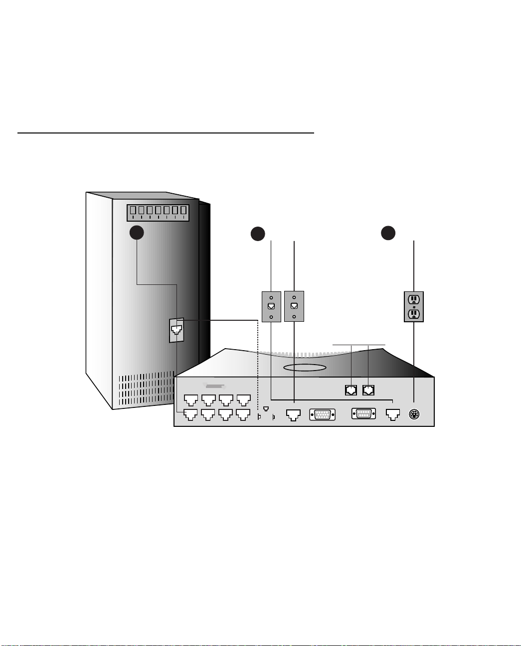
1. Connect the mini-DIN8 connector from the Power Adapter to the Power port, and plug the other end into an
electrical outlet.
2. Connect one end of one of the RJ-11 cables to the “Telco 1" port, and the other end to one of your wall
outlets.
Page 25

Making the Physical Connections 2-3
If you have two phone lines on a single wall outlet, this is the only T elco connection you need to make. The
pinout configuration for the lines on the Telco 1 port is shown in the following diagram:
1234
5678
Telco 1
Telco 2
Your first Telco number is carried on the inner pair and the second number on the outer pair.
3. If you have a second phone line with its own separate wall outlet, and want to use both built-in modems,
connect one end of one of the RJ-11 cables to the “Telco 2" port, and the other end to your second wall
outlet.
4. Connect the Ethernet cable to any of the Ethernet ports on the router.
(If you are connecting the router to an existing Ethernet hub, use Ethernet port #1 on the router and set the
crossover switch to the Uplink position.)
You should now have: the power adapter plugged in; the Ethernet cable connected between the router and
your computer; and the telephone cables connected between the router and the wall outlets.
5. Insert your Netopia CD and follow the instructions to install an Internet browser and the Adobe Acrobat
Reader, if you don’t already have them.
6. Now, run the SmartStart application.
SmartStart requires the following:
■ your computer must be Ethernet-capable, that is it must have both an Ethernet card and TCP/IP stack
software. See “Before running SmartStart” on page 3-1.
■ your computer and the Netopia R2121 are powered ON.
■ the computer running SmartStart and the Netopia R2121 to be configured must be on the same Ether-
net segment; there can be no intervening routers. Repeaters, such as 10Base-T hubs, are acceptable.
Go to the section “Setting up your Router with the SmartStart Wizard” on page 3-3 for details on running
SmartStart.
Page 26
2-4 User’s Reference Guide
Netopia R2121 Dual Analog Router Back Panel Ports
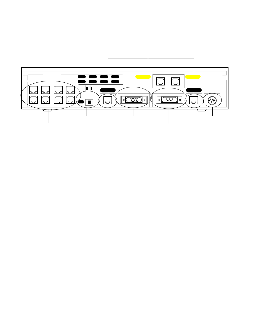
The figure below displays the back of the Netopia R2121 with Dual Analog.
Netopia R2121 with Dual Analog back panel
Telco or line ports
Ethernet
Crossover switch
8 port Ethernet hub
8
473
Normal/Uplink
1
625
1
Telco 2 Telco 1
Auxiliary Console Power
Phone 1Phone 2
Auxiliary port
Console port
Power port
Page 27

Making the Physical Connections 2-5
The following table describes all the Netopia R2121 Dual Analog Router back panel ports.
Port Description
Power port a mini-DIN8 power adapter cable connection.
Telco 1 port a red RJ-11 telephone jack labelled “Telco 1".
Console port a DE-9 Console port for a direct serial connection to the console screens. You
may use this if you are an experienced user and choose not to use SmartStart.
See “Connecting a local terminal console cable to your router” on page 6-3.
Phone 1 and 2 two yellow Phone ports above the Console port for attaching analog telephone
devices, such as phones or fax machines to share the telephone lines.
Auxiliary port an HD-15 Auxiliary port for attaching an external modem or the optional
AppleTalk kit.
Telco 2 port a red RJ-11 telephone jack labelled “Telco 2".
If you have only one telephone wall jack, supporting either one or two telephone
numbers, use the “T elco 1" port. “Telco 1" supports two phone connections on
a single line; “Telco 2" supports a single phone connection.
Crossover switch a crossover switch with Normal and Uplink positions. If Ethernet Port #1 is used
for a direct Ethernet connection between a computer and the router, set the
switch to the Normal position. If you are connecting the router to an Ethernet
hub, use Ethernet port #1 on the router and set the switch to the Uplink
position.
8-port Ethernet hub Eight Ethernet jacks. Y ou will use one of these to configure the Netopia R2121.
For a new installation, you use the Ethernet connection. SmartStart only works
over Ethernet. Later, if you want to do some advanced configuration, you can
Telnet to the Console-based management screens via the Ethernet connection.
You may also use the Console connection to run the Console-based
management using a direct serial connection. You may either connect your
computer directly to any of the Ethernet ports on the router, or connect both
your computer and the router to an existing Ethernet hub on your LAN.
Page 28
2-6 User’s Reference Guide
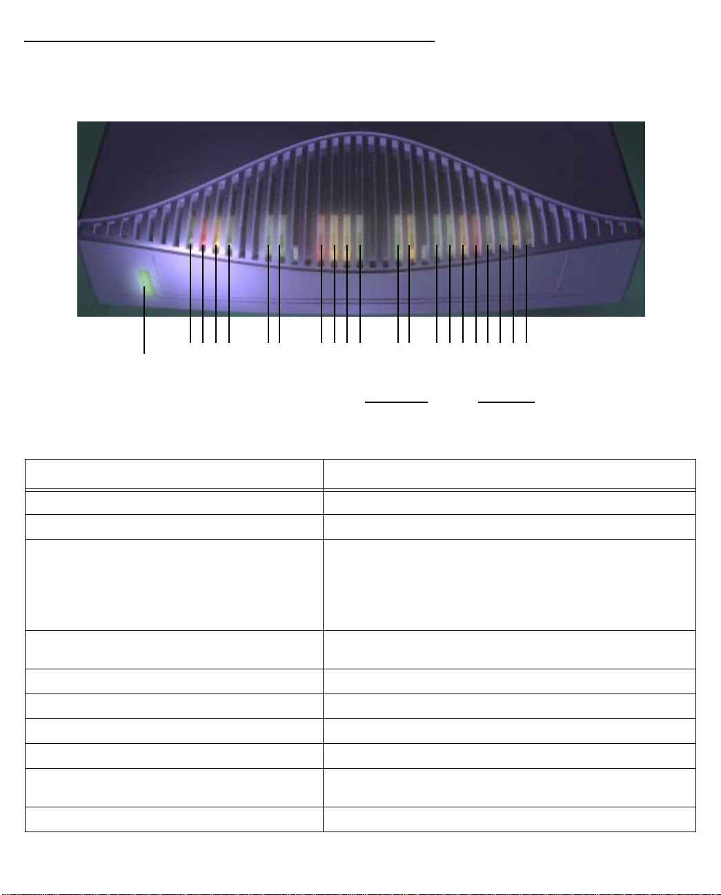
Netopia R2121 Dual Analog Router Status Lights
The figure below represents the Netopia R2121 status light (LED) panel.
Netopia R2121 LED front panel
2 3 4 5 6 7 8 9 10 11 12 13 14 15 16171819 20 21
1
Ring
Receive
Carrier
Power
Transmit
Modem 1 Modem 2 LAN
Console
Auxiliary
Ring
Receive
Carrier
Transmit
Activity
Collision
Link/Receive
Ethernet
The following table summarizes the meaning of the various LED states and colors:
When this happens... the LEDs...
when the corresponding line is ringing 2 and 8 flash yellow
when the modem has carrier 3 and 9 are green.
when the line is busy for a non-data call 3 and 9 flash red.
Includes both directly attached and extension phones. (Red,
for when the line is not connected and if the phone
extension is off the hook; orange, for when the attached
phone is off the hook.)
when the router initiates an incoming or
3 and 9 flash green
outgoing call
when data is transmitted 4 and 10 flash yellow.
when data is received 5 and 11 flash yellow.
when carrier is asserted 6 and 7 are green.
when data is transmitted or received 6 and 7 flash yellow.
when data is transmitted or received by the
12 flashes yellow.
ethernet controller
when the Ethernet interface detects a collision 13 flashes red.
Page 29

Making the Physical Connections 2-7
When this happens... the LEDs...
when link is detected 14 though 21 are solid green.
when data is received on their respective ports 14 though 21 flash green
Page 30

2-8 User’s Reference Guide
Page 31

Setting up your Router with the SmartStart Wizard 3-1
CCCChhhhaaaapppptttteeeerrrr 33
SSSSeeeettttttttiiiinnnngggg uuuupppp yyyyoooouuuurrrr RRRRoooouuuutttteeeerrrr wwwwiiiitttthhhh tttthhhheeee SSSSmmmmaaaarrrrttttSSSSttttaaaarrrrtttt WWWWiiiizzzzaaaarrrrdd
Once you’ve connected your router to your computer and your telecommunications line and installed a web
browser, you’re ready to run the Netopia SmartStart™ Wizard. The SmartStart Wizard will help you set up the
router and share the connection. The SmartStart Wizard walks you through a series of questions and based on
your responses automatically configures the router for connecting your LAN to the Internet or to your remote
corporate network.
The SmartStart Wizard will:
■ automatically check your Windows 95, 98, or NT PC’s TCP/IP configuration to be sure you can accept a
dynamically assigned IP address, and change it for you if it is not set for dynamic addressing
■ check the physical connection from your computer to your router without your having to enter an IP address
■ assign an IP address to your router
■ allow you to register with a new ISP if you don’t already have one (for analog modem and ISDN models).
For a list of ISPs that support Netopia Routers in North America, see the Netopia website at
http://www.netopia.com.
■ (for analog modem or ISDN models) allow you to enter your dial-up telephone numbers and other
information, dial up and test your connection to your chosen ISP or other remote site
33
dd
Before running SmartStart
Be sure you have connected the cables and power source as described in Step 1 “Connect the Router” guide
contained in your Netopia folio.
Before you launch the SmartStart application, make sure your computer meets the following requirements:
PC Macintosh
System
software
Connectivity
software
Connectivity
hardware
Browser
software
Windows 95, 98, or NT operating system MacOS 7.5 or later
TCP/IP must be installed and properly
configured. See “Configuring TCP/IP on
Windows 95, 98, or NT computers” on
page 3-9
Ethernet card (10Base-T) Either a built-in or third-party Ethernet card
Netscape Communicator™ or Microsoft Internet Explorer, included on the Netopia CD.
Required for web-based registration and web-based monitoring.
MacTCP or Open Transport TCP/IP must be
installed and properly configured. See
“Configuring TCP/IP on Macintosh
computers” on page 3-13.
(10Base-T)
Page 32

3-2 User’s Reference Guide
PC Macintosh
Notes:
• The computer running SmartStart must be on the same Ethernet cable segment as the Netopia R2121.
Repeaters, such as 10Base-T hubs between your computer and the Netopia R2121, are acceptable, but
devices such as switches or other routers are not.
• SmartStart for the PC will set your TCP/IP control panel to “Obtain an IP address automatically” if it is
not already set this way. This will cause your computer to reboot. If you have a specified IP address
configured in the computer, you should make a note of it before running SmartStart, in case you do not
want to use the dynamic addressing features built in to the Netopia Router and need to restore the fixed IP
address.
Page 33

Setting up your Router with the SmartStart Wizard 3-3
Setting up your Router with the SmartStart Wizard
The SmartStart Wizard is tailored for your platform, but it works the same way on either a PC or a Macintosh.
Insert the Netopia CD, and in the desktop navigation screen that appears, launch the SmartStart Wizard
application.
SmartStart Wizard configuration screens
The screens described in this section are the default screens shipped on the Netopia CD. They
derive from two initialization (.ini) files included in the same directory as the SmartStart
application file. Your reseller or your ISP may have supplied you with customized versions of
these files.
■ If you have received a CD or diskette that has been customized by your reseller or ISP , you
can run the SmartStart Wizard directly from the CD or diskette and follow the instructions
your reseller or ISP provides. This makes your Netopia R2121 configuration even easier.
■ If you have received only the .ini files from your reseller or ISP, perform the following:
■ Copy the entire directory folder containing the SmartStart Wizard application from the
Netopia CD to your hard disk.
■ Copy the customized .ini files to the same directory folder that contains the Smart-
Start Wizard application, allowing the copy process to overwrite the original .ini files.
■ Run the SmartStart Wizard from your hard disk. You can then follow the instructions
your reseller or ISP provides.
The SmartStart Wizard presents a series of screens to guide you through the preliminary configuration of a
Netopia R2121. It will then create a connection profile using the information you supply to it.
Welcome screen. The first screen welcomes you to the
SmartStart Wizard configuration utility.
Click the Next button after you have responded to the
interactive prompts in each screen.
The Help button will display useful information to assist
you in responding to the interactive prompts.
Page 34

3-4 User’s Reference Guide
Easy or Advanced options screen. Y ou can choose either
Easy or Advanced setup.
■ If you choose Easy, SmartStart automatically uses
the preconfigured IP addressing setup built into your
router. This is the best choice if you are creating a
new network or don’t already have an IP addressing
scheme on your new network.
If you choose Easy, you will see a “Connection Test
screen,” like the one shown below while SmartStart
checks the connection to your router.
■ If you choose Advanced, skip to page 3-8 now. The
SmartStart Wizard displays the “Router IP Address
screen” on page 3-8, in which you can choose ways
to modify your router’s IP address.
Easy option
Connection Test screen. SmartStart tests the
connection to the router. While it is testing the
connection, a progress indicator screen is displayed and
the router’s Ethernet LEDs flash.
When the test succeeds, SmartStart indicates success.
If the test fails, the wizard displays an error screen. If the test fails, check the following:
■ Check your cable connections. Be sure you have connected the router and the computer properly, using the
correct cables. Refer to the Step 1 “Connect the Router” sheet in your Netopia R2121 documentation folio.
■ Make sure the router is turned on and that there is an Ethernet connection between your computer and the
router.
■ Check the TCP/IP control panel settings to be sure that automatic IP Addressing (Windows) or DHCP
(Macintosh) is selected. If you are using a Windows PC, SmartStart will automatically detect a static IP
address and offer to configure the computer for automatic addressing. On a Macintosh computer, you must
manually set the TCP/IP Control Panel to DHCP. See “Configuring TCP/IP on Macintosh computers” on
page 3-13. If you currently use a static IP address outside the 192.168.1.x network, and want to continue
using it, use the Advanced option to assign the router an IP address in your target IP range. See “Advanced
option” on page 3-8.
■ If all of the above steps fail to resolve the problem, reset the router to its factory default settings and rerun
SmartStart.
Page 35

Setting up your Router with the SmartStart Wizard 3-5
When the test is successful, you will see the “Manual or Automated Connection Profile screen,” shown below.
Manual or Automated Connection Profile screen. The
SmartStart Wizard asks you to select a method of
creating a connection profile. The connection profile tells
your router how to communicate with your ISP or other
remote site, such as your corporate office. Y ou can select
either ISP Automation or Manual Entry.
Options are explained below.
Make your selection and click Next.
If you select ISP Automation, SmartStart offers you the option of choosing one of several Netopia ISP
partners that support the Netopia R2121. You then see the “Internet Service Provider Selection screen” on
page 3-5.
If you select Manual Entry, you must be prepared with the following information. You must enter:
■ Your dial-up number, sometimes referred to as an ISP POP number
■ Your Login name and Password. (These are case-sensitive.)
■ Any PBX or Centrex phone system dialing prefix (such as “9” for an outside line)
■ Your PPP authentication method. Options are: PAP (Password Authentication Protocol), CHAP (Challenge
Handshake Authentication Protocol), or None. Most ISPs use PAP; this is the default.
■ Your Domain Name Server (DNS); this entry must be an IP address in dotted decimal format. (for example,
192.168.4.10, not “joe.isp.com”)
■ Optionally, an alternate DNS if your ISP provided one
If you select Manual Entry, the “Connection Profile screen,” shown “Connection Profile screen” on page 3-6
appears.
Internet Service Provider Selection screen. Select an
ISP from the list of Netopia ISP partners who have
provided information for automatic setup. Choose
Generic ISP if your ISP is not included on the list. If you
don’t already have an account with the selected ISP, call
and order service using the listed customer service
telephone number.
When you have done this, click Next.
■ Most ISPs will provide you with information for you to enter in the “Connection Profile screen” on page 3-6
over the phone using the toll-free phone number shown in the scrolling list. Generally, they will provide you
Page 36

3-6 User’s Reference Guide
with:
■ Your dial-up number, sometimes referred to as an ISP POP number
■ Your Login name and Password. (These are case-sensitive.)
Note: Your ISP may provide you with additional values such as “Remote IP Gateway” or “Subnet Mask.”
These entries are not required for the SmartStart Wizard to configure your router.
If you have a PBX or Centrex phone system, you may need a dialing prefix (such as “9” for an outside line).
You will enter that information in the “Connection Profile screen,” shown below.
Connection Profile screen. Enter your ISP-supplied
configuration information mentioned above. All fields
must be filled in except the Alternate DNS field if your ISP
does not provide one. If your ISP appeared in the
“Internet Service Provider Selection screen” on page 3-5
your ISP will already have provided much of the
information required for the connection, and these fields
will appear grayed-out.
When you have done this, click Next.
The “Name and Password screen” on page 3-6 appears;
this is where you enter the username and password for
your connection to your ISP.
Name and Password screen. Enter the username and
password that identifies you to your ISP. Your name and
password can be up to 32 characters each.
Note: Some automated profiles already specify name and
password for you. in this case, the screen is filled out for
you and automatically skipped.
When you have done this, click Next.
The SmartStart Wizard then posts your connection profile
information to your router.
Now the “Connection Profile Test screen,” (shown below)
appears. It allows you to test your connection to your ISP
using the connection profile you have just created.
Page 37

Setting up your Router with the SmartStart Wizard 3-7
Connection Profile Test screen. SmartStart tests your
connection profile by attempting to connect to your ISP.
To test the connection profile with your ISP, click Next.
While the test is running, SmartStart reports its progress
in a brief succession of dialog boxes as described below.
Available Line Test Progress screen. SmartStart tests to
see if the router can place calls on your telephone line.
While it is testing the connection, a dialog box is
displayed and the LEDs flash.
Connection Test Progress screen. SmartStart displays a
dialog box showing you that your connection profile is
being tested. If this test fails, check the physical
connections between the computer, the router, and the
wall jack or jacks. Check for errors in any manual entries
you made during the configuration process.
Final screen. When the connection tests successfully,
SmartStart displays a screen telling you that your
configuration is now complete.
In most cases, this SmartStart configuration is all that you need to get your router up and running and
connected to the Internet. However, you may want to take advantage of additional features or special
configuration options available through the console-based configuration interface. For detailed instructions, see
“Console-based Management” on page 6-1.
Page 38
3-8 User’s Reference Guide
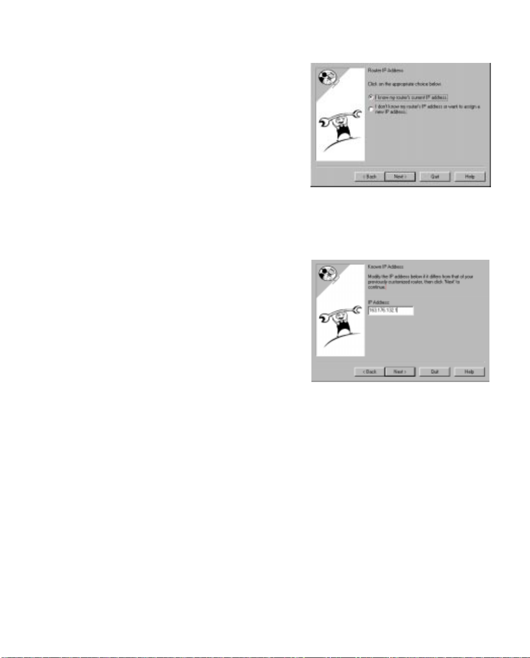
Advanced option
Router IP Address screen. If you selected the Advanced
option in the “Easy or Advanced options screen” on
page 3-4, SmartStart asks you to choose between
entering the router’s current IP address and assigning an
IP address to the router.
If the router has already been assigned an IP address,
select the first radio button. If you do this, the “Known IP
Address screen,” appears (shown below.)
If you want to reconfigure the router with a new IP address
and subnet mask, select the second radio button. If you
do this, the “New IP Address screen” on page 3-9
appears.
When you have done this, click Next.
Known IP Address screen. SmartStart displays a
recommended address for the router based on the IP
address of the computer.
If you know the router has an IP address different from
the default value, enter it now. Otherwise, accept the
recommended address.
When you have done this, click Next.
SmartStart tests the connection to your router.
SmartStart then returns you to an “Connection Profile
screen” on page 3-6.
Page 39

New IP Address screen. If you want to change the
router’s IP address, you enter the new IP address, the
subnet mask, and the router’s serial number in this
screen. Remember, the serial number is on the bottom of
the router. It is also found in your documentation folio.
Note: Forcing a new IP address may turn off the Netopia
R2121’s IP address serving capabilities, if you assign an
IP address and subnet mask outside the router’s current
IP address serving pool. The Netopia R2121 does not
allow an invalid address to be served. Use this option
with caution.
When you have done this, click Next.
SmartStart forces the new IP address into the router,
tests the connection, and then resets the router.
SmartStart then returns you to the “Manual or Automated
Connection Profile screen” on page 3-5.
Sharing the Connection
Setting up your Router with the SmartStart Wizard 3-9
Configuring TCP/IP on Windows 95, 98, or NT computers
Configuring TCP/IP on a Windows computer requires the following:
■ An Ethernet card (also known as a network adapter)
■ The TCP/IP protocol must be “bound” to the adapter or card
Page 40

3-10 User’s Reference Guide
Dynamic configuration (recommended)
If you configure your Netopia R2121 using SmartStart, you can accept the dynamic IP address assigned by your
router. The Dynamic Host Configuration Protocol (DHCP) server, which enables dynamic addressing, is enabled
by default in the router. If your PC is not set for dynamic addressing, SmartStart will offer to do this for you
when you launch it. In that case, you will have to restart your PC and relaunch SmartStart. If you configure your
PC for dynamic addressing in advance, SmartStart need only be launched once. To configure your PC for
dynamic addressing do the following:
1. Go to the Start
Menu/Settings/Control
Panels and double click
the Network icon. From
the Network components
list, select the
Configuration tab.
2. Select TCP/IP-->Your Network Card. Then select
Properties. In the TCP/IP Properties screen (shown
below), select the IP Address tab. Click “Obtain an IP
Address automatically.”
3. Click on the DNS Configuration tab. Click Disable DNS.
DNS will be assigned by the router with DHCP.
4. Click OK in this window, and the next window. When
prompted, reboot the computer.
Note: Y ou can also use these instructions to configure other computers on your network to accept IP addresses
served by the Netopia R2121.
Page 41

Setting up your Router with the SmartStart Wizard 3-11
Static configuration (optional)
If you are manually configuring for a fixed or static IP address, perform the following:
1. Go to Start Menu/Settings/Control Panels and double click the Network icon. From the Network
components list, select the Configuration tab.
2. Select TCP/IP-->Y our Network Card. Then select Properties. In the TCP/IP Properties screen (shown below),
select the IP Address tab. Click “Specify an IP Address.”
Enter the following:
IP Address: 192.168.1.2
Subnet Mask: 255.255.255.0
This address is an example of one that can be used to configure the router with the Easy option in the
SmartStart Wizard. Y our ISP or network administrator may ask you to use a different IP address and subnet
mask.
Page 42

3. Click on the Gateway tab (shown below).
Under “New gateway,” enter
192.168.1.1. Click Add. This is the
Netopia R2121’s pre-assigned IP
address.
4. Click OK in this window, and the next window. When prompted, reboot the computer.
Click on the DNS Configuration tab. Click Enable DNS.
Enter the following
information:
Host: Type the name
you want to give to
this computer.
Domain: Type your
domain name. If you
don't have a domain
name, type your ISP's
domain name; for
example,
netopia.com.
DNS Server Search
Order: Type the
primary DNS IP
address given to you
by your ISP. Click
Add. Repeat this process for the secondary DNS.
Domain Suffix Search Order: Enter the same domain
name you entered above.
Note: You can also use these instructions to configure other computers on your network with manual or static
IP addresses. Be sure each computer on your network has its own IP address.
Page 43

Setting up your Router with the SmartStart Wizard 3-13
Configuring TCP/IP on Macintosh computers
The following is a quick guide to configuring TCP/IP for MacOS computers. Configuring TCP/IP in a Macintosh
computer requires the following:
■ You must have either Open Transport or Classic Networking (MacTCP) installed.
Note: If you want to use the Dynamic Host Configuration Protocol (DHCP) server built into your Netopia
R2121 to assign IP addresses to your Macintoshes, you must be running Open Transport, standard in
MacOS 8, and optional in earlier system versions. You can have your Netopia R2121 dynamically assign IP
addresses using MacTCP; however, to do so requires that the optional AppleTalk kit be installed which can
only be done after the router is configured.
■ You must have built-in Ethernet or a third-party Ethernet card and its associated drivers installed in your
Macintosh.
Dynamic configuration (recommended)
If you configure your Netopia R2121 using SmartStart, you can accept the dynamic IP address assigned by your
router. The Dynamic Host Configuration Protocol (DHCP), which enables dynamic addressing, is enabled by
default in the router. To configure your Macintosh computer for dynamic addressing do the following:
1. Go to the Apple menu. Select Control Panels and then
TCP/IP.
2. With the TCP/IP window open, go to the Edit menu and
select User Mode. Choose Basic and click OK.
3. In the TCP/IP window, select “Connect via: Ethernet” and
“Configure: Using DHCP Server.”
Note: Y ou can also use these instructions to configure other computers on your network to accept IP addresses
served by the Netopia R2121.
Page 44

3-14 User’s Reference Guide
Static configuration (optional)
If you are manually configuring for a fixed or static IP address,
perform the following:
1. Go to the Apple menu. Select Control Panels and then
TCP/IP or MacTCP.
2. With the TCP/IP window open, go to the Edit menu and
select User Mode. Choose Advanced and click OK.
Or, in the MacTCP window, select Ethernet and click the
More button.
3. In the TCP/IP window or in the MacTCP/More window, select or type information into the fields as shown in
the following table.
Option: Select/Type:
Connect via: Ethernet
Configure: Manually
IP Address: 192.168.1.2
Subnet mask: 255.255.255.0
Router address: 192.168.1.1
Name server address: Enter the primary and secondary name
server addresses given to you by your ISP
Implicit Search Path:
Starting domain name:
4. Close the TCP/IP or MacTCP control panel and save the settings.
5. If you are using MacTCP, you must restart the computer. If you are using Open Transport, you do not need
to restart. These are the only fields you need to modify in this screen.
Note: You can also use these instructions to configure other computers on your network with manual or static
IP addresses. Be sure each computer on your network has its own IP address.
Enter your domain name; if you do not have
a domain name, enter the domain name of
your ISP
Page 45

Setting up your Router with the SmartStart Wizard 3-15
Dynamic configuration using MacIP (optional)
If you want to use MacIP to dynamically assign IP addresses to the Macintosh computers on your network you
must install the optional AppleTalk feature set kit.
Note: You cannot use MacIP dynamic configuration to configure your Netopia R2121 Dual Analog Router
because you must first configure the router in order to enable AppleTalk.
Once the AppleTalk kit is installed, you can configure your Macintoshes for MacIP. To configure dynamically
using MacIP, perform the following:
Using Open Transport TCP/IP
1. Go to the Apple menu. Select Control Panels and then TCP/IP.
2. With the TCP/IP window open, go to the Edit menu and select User Mode. Choose Advanced and click OK.
3. In the TCP/IP window, select or type information into the fields as shown in the following table.
TCP/IP Option: Select/ Type:
Connect via: AppleTalk (MacIP)
Configure: Using MacIP server
MacIP Server zone: (select available zone)
Name server address: Enter the primary and secondary name server
addresses given to you by your ISP
Implicit Search Path:
Starting domain name:
Enter your domain name; if you do not have a
domain name, enter the domain name of your ISP
4. Close the TCP/IP control panel and save the settings.
These are the only fields you need to modify in these screens.
Page 46

3-16 User’s Reference Guide
Using Classic Networking (MacTCP)
1. Go to the Apple Menu. Select Control Panels and then Network.
2. In the Network window, select EtherTalk.
3. Go back to the Apple menu. Select Control Panels and then MacTCP.
4. Select EtherTalk.
From the pull-down menu under EtherTalk, select an available zone; then click the More button.
In the MacTCP/More window select the Server radio button. If necessary, fill in the Domain Name Server
Information given to you by your administrator.
5. Restart the computer.
These are the only fields you need to modify in these screens.
Note: More information about configuring your Macintosh computer for TCP/IP connectivity through a Netopia
R2121 can be found in T echnote NIR_026, “Open T ransport and Netopia Routers,” located on the Netopia Web
site.
Page 47

Monitoring with SmartView 4-1
CCCChhhhaaaapppptttteeeerrrr 44
MMMMoooonnnniiiittttoooorrrriiiinnnngggg wwwwiiiitttthhhh SSSSmmmmaaaarrrrttttVVVViiiieeeeww
This chapter discusses SmartView, the Netopia R2121’s device and network web-based monitoring tool. This
tool can provide statistical information, report on current network status, record events, and help in diagnosing
and locating problems.
This section covers the following topics:
■ “SmartView overview” on page 4-1
■ “Navigating SmartView” on page 4-2
44
ww
SmartView overview
SmartView is a Java-based applet that runs in a web browser window. It intermittently polls the Router for
information to monitor the Router’s state and control connection and disconnection of Connection Profiles.
SmartView should run under any Java Virtual Machine (JVM)-enabled browser, and is therefore platform
independent.
Note: The SmartView applet will only run under Java-enabled browsers. Be sure that the browser you are using
is at least Microsoft Internet Explorer Version 3.0 or higher, or Netscape Navigator Version 3.0 or Communicator
Version 4.0 or higher. If your browser does not meet this requirement, you can upgrade with a browser supplied
on the Netopia CD.
Using SmartView, you can view your Router’s:
Machine Information:
Model Profile Name Device
Firmware Version Dial-out Profile WAN
Ethernet IP address Dial Number Update
Date Bandwidth Type
Time Dial Direction (In/Out)
LED status Remote Address
Connection Profile
Information:
Gateway
DNS
DNS Alternate
Connect/Disconnect
History Logs:
Page 48

4-2 User’s Reference Guide
Navigating SmartView
You access the SmartView monitor by launching your web browser and entering the URL:
“http://
where
Once you have invoked the SmartView pages, you should bookmark SmartView in your browser for easy access.
SmartView uses a tabbed view to categorize information and reduce the amount of information displayed at
once. You click on the tabs to display the different informational categories.
router_IP_Address
router_IP_address
/smartview.html”
is the address of your router.
General Machine Information page
In addition to the static machine information about your router, such as model and firmware version, SmartView
displays a real-time visual representation of the Netopia R2121’s status lights (LEDs). This is particularly
useful if the router is located out of visual range, such as in a wiring closet.
Page 49

Monitoring with SmartView 4-3
Connection Profiles page
The Connection Profiles page displays the currently active Connection Profile, and any alternate profiles you
may have created. You can switch from one Connection Profile to another by disconnecting from one, and
connecting to another.
■ To hang up the current connection, and establish the one you select, click the Disconnect button for the
currently active Connection Profile.
■ Click the tab for the Connection Profile you want to activate.
■ Click the Connect Button for this Connection Profile.
Event History pages
The Netopia R2121 records certain relevant occurrences in event histories. Event histories are useful for
diagnosing problems because they list what happened before, during, and after a problem occurs. You can view
two different event histories: one for the router’s system and one for the WAN. The Netopia R2121’s built-in
battery backup prevents loss of event history from a shut down or reset.
The Router’s event histories are structured to display the most recent events first, and to make it easy to
distinguish error messages from informational messages. Error messages are prefixed with an asterisk. Both
the WAN Event History and the Device Event History retain records of up to 128 of the most recent events. Y ou
can refresh the Event history logs by clicking the Update button.
Page 50

4-4 User’s Reference Guide
Device Event History page
WAN Event History page
Page 51

Monitoring with SmartView 4-5
Standard HTML Web-based monitoring pages
You can also view Connection Profile information and Event Histories in the web-based monitoring pages. These
pages are provided for users without Java-enabled browsers. Unlike the SmartView pages, they are not
dynamically updated.
You access the web-based monitoring pages by launching your web browser and entering the URL:
“http://
where
■ To view your Connection Profile information, click the Connection Profiles icon.
router_IP_Address
router_IP_address
”
is the address of your router.
■ To view Event Histories, click the Statistics icon.
■ To go to SmartView, if your browser is Java-enabled, click the SmartView icon.
For information on other advanced monitoring tools built into your Netopia R2121 Dual Analog Router, see
“Monitoring Tools” on page 13-1.
Page 52

4-6 User’s Reference Guide
Page 53

Connecting Your Local Area Network 5-1
CCCChhhhaaaapppptttteeeerrrr 55
CCCCoooonnnnnnnneeeeccccttttiiiinnnngggg YYYYoooouuuurrrr LLLLooooccccaaaallll AAAArrrreeeeaaaa NNNNeeeettttwwwwoooorrrrkk
This chapter describes how physically to connect the Netopia R2121 to your local area network (LAN). Before
you proceed, make sure the Netopia R2121 is properly configured. You can customize the Router’s
configuration for your particular LAN requirements using Console-based Management (see “Console-based
Management” on page 6-1).
This section covers the following topics:
■ “Overview” on page 5-1
■ “Readying computers on your local network” on page 5-1
■ “Connecting to an Ethernet network” on page 5-3
■ “Adding a third modem” on page 5-5
■ “Connecting to a LocalTalk network” on page 5-6
55
kk
Overview
You can connect the Netopia R2121 to an IP or IPX network that uses Ethernet.
If you have purchased the AppleTalk feature expansion kit, you can also connect the Router to a LocalTalk
network that uses PhoneNET cabling.
Additionally, you can connect a third (external) modem. See “Adding a third modem,” below.
Caution!
Before connecting the Netopia R2121 to any AppleTalk LANs that contain other AppleTalk routers, you should
read “Routers and seeding” on page 12-3.
See the sections later in this chapter for details on how to connect the Netopia R2121 to different types of
networks.
Readying computers on your local network
PC and Macintosh computers must have certain components installed before they can communicate through
the Netopia R2121. The following illustration shows the minimal requirements for a typical PC or Macintosh
computer.
Page 54

5-2 User’s Reference Guide
Application software
TCP/IP stack
Ethernet/EtherTalk/LocalTalk Driver
Your PC
or Macintosh
computer
To the Netopia R2121
Application software: This is the software you use to send e-mail, browse the World Wide Web, read
newsgroups, etc. These applications may require some configuration. Examples include the Eudora e-mail
client, and the web browsers Microsoft Internet Explorer and Netscape Navigator.
TCP/IP stack: This is the software that lets your PC or Macintosh communicate using Internet protocols.
TCP/IP stacks must be configured with some of the same information you used to configure the Netopia
R2121. There are a number of TCP/IP stacks available for PC computers. Windows 95 includes a built-in
TCP/IP stack. See “Configuring TCP/IP on Windows 95, 98, or NT computers” on page 3-9. Macintosh
computers use either MacTCP or Open Transport. See “Configuring TCP/IP on Macintosh computers” on
page 3-13.
Ethernet: Ethernet hardware and software drivers enable your PC or Macintosh computer to communicate on
the LAN.
EtherTalk and LocalTalk: These are AppleTalk protocols used over Ethernet.
Once the Netopia R2121 is properly configured and connected to your LAN, PC and Macintosh computers that
have their required components in place will be able to connect to the Internet or other remote IP networks.
Page 55

Connecting Your Local Area Network 5-3
Connecting to an Ethernet network
The Netopia R2121 supports Ethernet connections through its eight Ethernet ports. The Router automatically
detects which Ethernet port is in use.
You can connect either 10Base-T or EtherWave Ethernet networks to the Netopia R2121. The following table
displays some important attributes of these types of Ethernet.
Attribute EtherWave 10Base-T
Max. length of backbone,
branch, or end to end (cable
length)
Cable type
Netopia R2121 port used Ethernet Ethernet
Other restrictions
330 feet
(100 meters)
Twisted pair
(10Base-T)
Maximum 8
devices (daisy
chained)
330 feet
(100 meters)
Twisted pair
(10Base-T)
No daisy
chain
Page 56

5-4 User’s Reference Guide
10Base-T
You can connect a standard 10Base-T Ethernet network to the Netopia R2121 using any of its available
Ethernet ports.
Netopia R2121 back panel
Ethernet
8
473
Normal/Uplink
1
The Netopia R2121 in a 10Base-T network
625
1
Telco 2 Telco 1
Auxiliary Console Power
Ethernet
8
4
Normal/
1
Phone 1Phone 2
To connect your 10Base-T network to the Netopia R2121 through an Ethernet port, use a 10Base-T cable with
RJ-45 connectors.
If you have more than eight devices to connect, you can attach additional devices using either a 10Base-T hub
or an EtherWave™ daisy chain, or some combination of both.
Page 57

Connecting Your Local Area Network 5-5
■ If you add devices connected through a hub, connect the hub to Ethernet port number 1 on the Netopia
R2121 and set the Normal/Uplink switch to Uplink.
When there are no more free ports on the 10Base-T hub, the network can be extended using EtherWave, a daisy-chainable
Ethernet solution from Farallon.
LaserWriter
EtherWave
Printer Adapter
EtherWave
ISA Card
MacintoshPC PC
EtherWave
NuBus Card
EtherWave
Transceiver
Ethernet
8
4
Normal/
1
10BASE-T
Hub
Adding a third modem
You may wish to add a third (external) modem to gain additional speed for your Internet connection. You will
need to obtain the special external modem cable either from your reseller or directly from Netopia. Refer to the
sheet of optional feature set add-ons in your Netopia R2121 documentation folio.
Netopia R2121 Auxiliary port for connecting a third modem
Ethernet
8
473
Normal/Uplink
1
625
1
Telco 2 Telco 1
Auxiliary Console Power
Phone 1Phone 2
Auxiliary connection port
HD-15 (female)
By default, the Auxiliary port on your Netopia R2121 is enabled for an external asynchronous modem. This
means that all you have to do is connect your modem to the Auxiliary port and configure its settings in the Line
Configuration screens under the WAN Configuration menu. For detailed configuration instructions see
“Specifying telephone connections” on page 9-2.
Page 58

5-6 User’s Reference Guide
For pinout information on the HD-15 to DB-25 modem cable, see “Pinouts for Auxiliary Port Modem Cable,” in
Appendix G, “Technical Specifications and Safety Information.”
Connecting to a LocalTalk network
If you have purchased the AppleTalk feature expansion kit, you can also connect the Router to an AppleTalk
network that uses either Ethernet or LocalTalk. Refer to the sheet of optional feature set add-ons in your
Netopia R2121 documentation folio.
The AppleTalk feature expansion kit includes a dual RJ-11 PhoneNET® connector that attaches to the Auxiliary
port on the Netopia R2121.
Netopia R2121 Auxiliary port for connecting to LocalTalk
Ethernet
8
473
Normal/Uplink
1
625
1
Telco 2 Telco 1
Auxiliary Console Power
Phone 1Phone 2
Auxiliary connection port
HD-15 (female)
Connect the male HD-15 end of the LocalTalk cable to the Auxiliary port on your Netopia R2121. Connect the
other end of the cable to your LocalTalk network. You can use only one connection on the Auxiliary port. You
cannot use both the PhoneNET connector and an external modem.
If your LocalTalk network is not based on standard PhoneNET cabling, use a PhoneNET-to-LocalTalk adaptor
cable available from Farallon division of Netopia. Connect the adaptor cable’s RJ-11 connector to the AppleT alk
cable’s PhoneNet connector. Connect the cable’s mini-DIN-3 connector to your LocalTalk network.
Be sure to observe the standard rules governing maximum cable lengths and limits on the number of nodes on
a PhoneNET network. The dual RJ-11 PhoneNET connector allows insertion in the LocalTalk daisy chain, or at
the end. If the device is connected at the end of the daisy chain, you must install the accompanying terminator.
Page 59

Wiring guidelines for PhoneNET cabling
Connecting Your Local Area Network 5-7
Topology
daisy chain n/a n/a 1800 ft.
backbone 4500 ft.
4-branch passive star* 1125 ft.
LocalTalk StarController
12-branch active star
* distance is per branch
Note: Make sure you
For detailed configuration instructions see “AppleTalk Setup” on page 12-1.
do not
connect your LocalTalk network to a Telco port or a POTS (Phone 1 and 2) port.
22 gauge
.642 mm
1372 m
343 m
3000 ft.
914 m
24 gauge
.510 mm
3000 ft.
229 m
750 ft.
229 m
2000 ft.
610 m
26 gauge
.403 mm
549 m
1800 ft.
549 m
450 ft.
137 m
1200 ft.
366 m
Page 60

5-8 User’s Reference Guide
Page 61

PPPPaaaarrrrtttt IIIIIIII:::: AAAAddddvvvvaaaannnncccceeeedddd CCCCoooonnnnffffiiiigggguuuurrrraaaattttiiiioooonn
nn
Page 62

User’s Reference Guide
Page 63

Console-based Management 6-1
CCCChhhhaaaapppptttteeeerrrr 66
CCCCoooonnnnssssoooolllleeee----bbbbaaaasssseeeedddd MMMMaaaannnnaaaaggggeeeemmmmeeeennnntt
Console-based management is a menu-driven interface for the capabilities built in to the Netopia R2121.
Console-based management provides access to a wide variety of features that the router supports. You can
customize these features for your individual setup. This chapter describes how to access and navigate the
console-based management screens.
This section covers the following topics:
■ “Connecting through a Telnet session” on page 6-2
■ “Connecting a local terminal console cable to your router” on page 6-3
■ “Navigating through the console screens” on page 6-4
Console-based management screens contain seven entry points to the Netopia Router configuration and
monitoring features. The entry points are displayed in the Main Menu shown below:
66
tt
Netopia R2121 v4.3
Easy Setup...
WAN Configuration...
System Configuration...
Utilities & Diagnostics...
Statistics & Logs...
Quick Menus...
Quick View...
You always start from this main screen.
■ The Easy Setup menus display and permit changing the values contained in the default Connection Profile
you created when you ran the SmartStart Wizard for initial configuration. Experienced users can also use
Easy Setup to initially configure the router directly through a console session without using SmartStart.
Easy Setup menus contain up to five descendant screens for viewing or altering these values. The number
of screens depends on whether you have optional features installed.
■ The WAN Configuration menu displays and permits changing your Connection Profile(s), creating or
deleting additional Connection Profiles, and configuring or reconfiguring the manner in which you may be
Page 64

6-2 User’s Reference Guide
using the router to connect to more than one service provider or remote site.
■ The System Configuration menus display and permit changing:
■ Network Protocols Setup. See “IP Setup, SmartIP and Network Address Translation” on page 10-1.
■ Filter Sets (Firewalls). See “Security” on page 14-1.
■ IP Address Serving. See “IP address serving” on page 10-16.
■ Date and Time. See “Date and Time” on page 8-11.
■ Console Configuration. See “Connecting a local terminal console cable to your router” on page 6-3.
■ SNMP (Simple Network Management Protocol). See “SNMP” on page 13-13.
■ Security. See “Security” on page 14-1.
■ Upgrade Feature Set. See “Upgrade Feature Set” on page 8-13.
■ Logging. See “Logging” on page 8-13.
■ The Utilities & Diagnostics menus provide a selection of seven tools for monitoring and diagnosing the
router's behavior, as well as updating the firmware and rebooting the system. See “Utilities and
Diagnostics” on page 15-1 for detailed information.
■ The Statistics & Logs menus display nine sets of tables and device logs that show information about your
router, your network and their history. See “Statistics & Logs” on page 13-4 for detailed information.
■ The Quick Menus screen is a shortcut entry point to twenty-two of the most commonly used configuration
menus that are accessed through the other menu entry points.
■ The Quick View menu displays at a glance current real-time operating information about your router. See
“Quick View status overview” on page 13-1 for detailed information.
Connecting through a Telnet session
Features of the Netopia R2121 may be configured through the console screens.
Before you can access the console screens through Telnet, you must have:
■ a network connection locally to the router or IP access to the router through the WAN port. This could be
the same connection as the one you used with SmartStart.
Note: Alternatively, you can have a direct serial console cable connection using the provided console cable
for your platform (PC or Macintosh) and the “Console” port on the back of the router. For more information
on attaching the console cable, see “Connecting a local terminal console cable to your router” on
page 6-3.
■ Telnet software installed on the computer you will use to configure the router
Page 65

Console-based Management 6-3
Configuring Telnet software
If you are configuring your router using a Telnet session, your computer must be running a Telnet software
program.
■ If you connect a PC with Microsoft Windows, you can use a Windows Telnet application or simply run Telnet
from the Start menu.
■ If you connect a Macintosh computer, you can use the NCSA Telnet program supplied on the Netopia
R2121 CD. You install NCSA Telnet by simply dragging the application from the CD to your hard disk.
Connecting a local terminal console cable to your router
You can perform all of the System Configuration activities for your Netopia R2121 through a local serial console
connection using terminal emulation software, such as HyperTerminal provided with Windows95 on the PC, or
ZTerm, included on the Netopia CD, for the Macintosh.
The Netopia R2121 back panel has a connector labeled “Console” for attaching the Router to either a PC or
Macintosh computer via the serial port on the computer. (On a Macintosh, the serial port is called the Modem
port or the Printer port.) This connection lets you use the computer to configure and monitor the Netopia R2121
via the console screens.
Ethernet
8
473
Normal/Uplink
1
625
1
Telco 2 Telco 1
Auxiliary Console Power
Phone 1Phone 2
Console connection port
DE-9 (male)
To connect the Netopia R2121 to your computer for serial console communication, use the supplied dual
console cable connector end appropriate to your platform:
■ one DE-9 connector end attaches to a PC
■ the mini-DIN8 connector end attaches to a Macintosh
■ the DE-9 end of the Console cable attaches to the Netopia R2121’s Console port
If you are configuring your router via a
terminal
session, your computer must be running a standard terminal
emulation or communications software program, such as those used with modems.
■ If you connect a PC with Microsoft Windows 95 or NT, you can use the HyperTerminal application bundled
with the operating system.
■ If you connect a Macintosh computer, you can use the ZTerm terminal emulation program on the supplied
Netopia R2121 CD.
Page 66

6-4 User’s Reference Guide
Launch your terminal emulation software and configure the communications software for the following values.
These are the default communication parameters that the Netopia R2121 uses.
Parameter Suggested Value
Terminal type PC: ANSI-BBS
Mac: ANSI, VT-100, or VT-200
Data bits 8
Parity None
Stop bits 1
Speed Options are: 9600, 19200, 38400, or 57600 bits per second
Flow Control None
Note: The router firmware contains an autobaud detection feature. If you are at any screen on the
serial console, you can change your baud rate and press Return (HyperTerminal for the PC
requires a disconnect). The new baud rate is displayed at the bottom of the screen.
Navigating through the console screens
Use your keyboard to navigate the Netopia R2121’s configuration screens, enter and edit information, and
make choices. The following table lists the keys to use to navigate through the console screens.
To... Use These Keys...
Move through selectable items in a screen or pop-up menu Up, Down, Left, and
Right Arrow
To set a change to a selected item or open a pop-up menu of
options for a selected item like entering an upgrade key
Change a toggle value (Yes/No, On/Off) Tab
Restore an entry or toggle value to its previous value Esc
Move one item up Up arrow or Control + k
Move one item down Down arrow or Control + j
Display a dump of the device event log Control + e
Display a dump of the WAN event log Control + f
Refresh the screen Control + L
Go to topmost selectable item <
Go to bottom right selectable item >
Return or Enter
Page 67

Easy Setup 7-1
CCCChhhhaaaapppptttteeeerrrr 77
EEEEaaaassssyyyy SSSSeeeettttuuuupp
This chapter describes how to use the Easy Setup console screens on your Netopia R2121 Dual Analog Router.
The Easy Setup console screens provide an alternate method for experienced users to set up their router’s
Connection Profiles without using SmartStart. After completing the Easy Setup console screens, your router will
be ready to connect to the Internet or another remote site.
77
pp
Easy Setup console screens
Using three Easy Setup console screens, you can:
■ modify a Connection Profile for your Router for the connection to your ISP or remote location;
■ set up IP addresses and IP address serving;
■ password protect configuration access to your Netopia R2121 Dual Analog Router;
How to access the Easy Setup console screens
To access the console screens, Telnet to the Netopia Router over your Ethernet network, or you can physically
connect with a serial console cable and access the Netopia Router with a terminal emulation program. See
“Connecting through a Telnet session” on page 6-2 or “Connecting a local terminal console cable to your
router” on page 6-3.
Note: Before continuing, make sure that you have the information that your telephone service provider, ISP, or
network administrator has given you to configure the Netopia Router.
The Netopia Router’s first console screen, Main Menu, appears in the terminal emulation window of the
attached PC or Macintosh when:
■ the Netopia Router is turned on
■ the computer is connected to the Netopia Router
■ the Telnet or terminal emulation software is running and configured correctly.
Page 68

7-2 User’s Reference Guide
A screen similar to the following appears:
Netopia R2121 v4.3
Easy Setup...
WAN Configuration...
System Configuration...
Utilities & Diagnostics...
Statistics & Logs...
Quick Menus...
Quick View...
Return/Enter goes to Easy Setup -- minimal configuration.
You always start from this main screen.
If you do not see the Main Menu, verify that:
■ the computer used to view the console screen has its serial port connected to the Netopia R2121’s
“Console” port or an Ethernet connection to one of its Ethernet ports. See “Connecting a local terminal
console cable to your router” on page 6-3 or “Connecting through a Telnet session” on page 6-2.
■ the Telnet or terminal emulation software is configured for the recommended values.
■ if you are connecting via the Console port, the console’s serial port is not being used by another device,
such as an internal modem, or an application. Turn off all other programs (other than your terminal
emulation program) that may be interfering with your access to the port.
■ you have entered the correct password, if necessary. Your Netopia R2121’s console access may be
password protected from a previous configuration. See your system administrator to obtain the password.
See Appendix A, “Troubleshooting,” for more suggestions.
Page 69

Beginning Easy Setup
To begin Easy Setup, select Easy Setup in the Main Menu, then press Return.
The Easy Setup Profile screen appears.
Connection Profile 1: Easy Setup Profile
Number to Dial: 12345678901234567890
Address Translation Enabled: Yes
Local WAN IP Address: 0.0.0.0
Remote IP Address: 127.0.0.2
Remote IP Mask: 255.0.0.0
PPP Authentication... PAP
Send User Name:
Send Password:
PREVIOUS SCREEN NEXT SCREEN
Enter the directory number for the remote network connection.
Enter basic information about your WAN connection with this screen.
Easy Setup 7-3
Easy Setup profile
The Easy Setup Profile screen is where you configure the parameters that control the Netopia R2121’s
connection to a specific remote destination, usually an ISP or a corporate site.
On a Netopia R2121 Dual Analog Router you can add up to 15 more connection profiles, for a total of 16. See
“Creating a new Connection Profile” on page 8-2.
1. Select Number to Dial and enter the telephone number you received from your ISP. This is the number the
Netopia R2121 dials to reach your ISP. Enter the number as you would dial it, including any required
prefixes (such as area, access, and long-distance dialing codes).
Note: When placing a multi-channel call, the answering equipment must either:
■ be in a “hunt group,” where a single telephone number services multiple lines, or
■ the answering side must implement MP or BAP as a method to advise the calling side what number(s)
to use.
ISPs or corporate IS groups will meet these conditions. For other non-standard dialup connections, you
should verify that one or the other of these conditions is true.
2. To enable address translation, toggle Address Translation Enabled to Yes. For more information on
Network Address Translation, see “IP Setup, SmartIP and Network Address Translation” on page 10-1.
3. Select Local WAN IP Address and enter the local WAN address your ISP gave you.
Page 70

7-4 User’s Reference Guide
The default address is 0.0.0.0, which allows for dynamic addressing, when your ISP assigns an address
each time you connect. However, you may enter another address if you want to use static addressing.
■ When using numbered interfaces, the Netopia Router will use its local WAN IP address and subnet
mask to send packets to the remote router. Both routers have WAN IP addresses and subnet masks
associated with the connection.
■ When using unnumbered interfaces, the Netopia Router will use either its local Ethernet IP address or
its NAT address (if so configured) and subnet mask to send packets to the remote router. Neither
router has a WAN IP address or subnet mask associated with this connection.
Note: If your ISP has not given you their IP or subnet mask addresses, then you may enter an IP address
such as 127.0.0.2, and an IP subnet mask such as 255.0.0.0. With these settings the router will get this
information dynamically when it connects to the remote site.
4. If your ISP uses unnumbered (system-based routing), select Remote IP Address and enter the IP address
your ISP gave you.
Then select Remote IP Mask and enter the IP subnet mask of the remote site you will connect to.
5. Select the PPP Authentication pop-up menu and choose the type of connection security your ISP told you
to use (PAP, CHAP , P AP-TOKEN, or CACHE-TOKEN). If you choose any of these authentication methods, go
to the next step. If your ISP does not use any of these authentication methods, choose None and skip to
the last step. When you create a connection profile from Easy Setup, the default setting is PAP.
6. If your ISP uses PAP or PAP-TOKEN, select Send User Name and enter the user name your ISP gave you to
connect. If you selected PAP, select Send Password and enter your password. If you selected PAP-TOKEN,
you don’t enter the password now. Your name and password can be up to 32 characters each.
If your ISP uses CHAP , select Send Host Name and enter the user name your ISP gave you to connect. Then
select Send Secret and enter the secret (CHAP term for password) your ISP gave you.
If your ISP uses CACHE-TOKEN, select Send User Name and enter the user name your ISP gave you to
connect. Select Send Password and enter your password.
7. Select NEXT SCREEN and press Return. The IP Easy Setup screen appears.
IP Easy Setup
The IP Easy Setup screen is where you enter information about your Netopia Router’s:
■ IP address
■ Subnet mask
■ Default gateway IP address
■ Domain name server IP address
■ IP address serving information, such as the number of client IP addresses and the 1st client address; and
Y ou should consult with your network administrator to obtain the information you will need. For more information
about setting up IP, see “IP Setup, SmartIP and Network Address Translation” on page 10-1.
Page 71

Easy Setup 7-5
IP Easy Setup
Ethernet IP Address: 192.168.1.1
Ethernet Subnet Mask: 255.255.255.0
Domain Name:
Primary Domain Name Server: 0.0.0.0
Default IP Gateway: 0.0.0.0
IP Address Serving: On
Number of Client IP Addresses: 100
1st Client Address: 192.168.1.100
PREVIOUS SCREEN NEXT SCREEN
Enter an IP address in decimal and dot form (xxx.xxx.xxx.xxx).
Set up the basic IP & IPX attributes of your Netopia in this screen.
1. Select Ethernet IP Address and enter the first IP address from the IP address range your ISP has given
you. This will be the Netopia Router’s IP address.
If Network Address Translation is enabled in the Easy Setup connection profile, the Ethernet IP Address
defaults to an address within a range reserved by the Internet address administration authority for use
within private networks, 192.168.1.1.
Because this is a private network address, it should never be directly connected to the Internet. Using NAT
for all your connection profiles will ensure this restriction. See “IP Setup, SmartIP and Network Address
Translation” on page 10-1 of this guide for more information.
2. Select Ethernet Subnet Mask and enter the subnet mask your ISP has given you. The Ethernet Subnet
Mask defaults to a standard class C mask (for unlimited user models; smaller, for restricted user models).
3. Select Domain Name and enter the domain name your ISP has given you.
4. Select Primary Domain Name Server and enter the IP address your ISP has given you.
5. The Default IP Gateway defaults to the remote IP address you entered in the Easy Setup connection
profile. If the Netopia Router does not recognize the destination of any IP traffic, it forwards that traffic to
this gateway.
Do not confuse the remote IP address and the default gateway’s IP address with the block of local IP
addresses you receive from your ISP. You use the local IP addresses for the Netopia R2121’s Ethernet port
and for IP clients on your local network. The remote IP address and the default gateway’s IP address
should point to your ISP’s router.
6. To use DHCP and (if installed) MacIP address serving, toggle IP Address Serving to On.
Note: For information about dynamic IP address serving, see “IP Setup, SmartIP and Network Address
Translation” on page 10-1.
Page 72

7-6 User’s Reference Guide
7. If IP Address Serving is On, select Number of Client IP Addresses. Then enter the number of available
host addresses for the Netopia R2121 Dual Analog Router to allocate to the client computers on your
network. This number defaults to the balance of the subnet addresses above the Netopia Router’s
address.
8. If IP Address Serving is On, select 1st Client Address and enter the first IP address in the set of allocated
served IP addresses.
9. Press Return. The Easy Setup Security Configuration screen appears.
Easy Setup Security
The Easy Setup Security Configuration screen lets you password-protect your Netopia R2121. Input your Write
Access Name and Write Access Password with names or numbers totaling up to eleven digits.
If you password protect the console screens, you will be prompted to enter the name and password you have
specified every time you log in to the console screens. Do not forget your name and password. If you do, you
will be unable to access any of the configuration screens.
Additional security features are available. See “Security” on page 14-1.
Easy Setup Security Configuration
It is strongly suggested that you password-protect configuration access to your
Netopia. By entering a Name and Password pair here, access via serial,
Telnet, SNMP and Web Server will be password-protected.
Be sure to remember what you have typed here, because you will be prompted for
it each time you configure this Netopia.
You can remove an existing Name and Password by clearing both fields below.
Write Access Name:
Write Access Password:
PREVIOUS SCREEN TO MAIN MENU RESTART DEVICE
Configure a Configuration Access Name and Password here.
The final step in configuring the Easy Setup console screens is to restart the Netopia R2121, so the
configuration settings take effect.
1. Select RESTART DEVICE. A prompt asks you to confirm your choice.
2. Select CONTINUE to restart the Netopia Router and have your selections take effect.
Note: You can also restart the system at any time by using the restart utility (see “Restarting the system” on
page 15-13) or by turning the Netopia Router off and on with the power switch.
Easy Setup is now complete.
Page 73

WAN and System Configuration 8-1
CCCChhhhaaaapppptttteeeerrrr 88
WWWWAAAANNNN aaaannnndddd SSSSyyyysssstttteeeemmmm CCCCoooonnnnffffiiiigggguuuurrrraaaattttiiiioooonn
This chapter describes how to use the console-based management screens to access and configure advanced
features of your Netopia R2121 Dual Analog Router. Y ou can customize these features for your individual setup.
These menus provide a powerful method for experienced users to set up their router’s connection profiles and
system configuration.
The next chapter “Managing Voice and Data Calls” on page 9-1 explains more of the Netopia R2121’s special
features for cost control and dial-in connections.
This section covers the following topics:
■ “Creating a new Connection Profile” on page 8-2
■ “System Configuration screens” on page 8-8
■ “Navigating through the System Configuration screens” on page 8-8
■ “System Configuration features” on page 8-9
88
nn
Page 74

8-2 User’s Reference Guide
Creating a new Connection Profile
Connection Profiles define the telephone and networking protocols necessary for the router to make a remote
connection. A Connection Profile is like an address book entry describing how the router is to get to a remote
site, or how to recognize and authenticate a remote user dialing in to the router. For example, to create a new
Connection Profile, you navigate to the WAN Configuration screen from the Main Menu, and select Add
Connection Profile.
Main
Menu
The Add Connection Profile screen appears.
Add Connection Profile
Profile Name: Profile 02
Profile Enabled: Yes
IP Enabled: Yes
IP Profile Parameters...
IPX Enabled: No
Data Link Encapsulation is: PPP
Data Link Options...
Telco Options...
ADD PROFILE NOW CANCEL
Return accepts * ESC cancels * Left/Right moves insertion point * Del deletes.
Configure a new Conn. Profile. Finished? ADD or CANCEL to exit.
WAN
Configuration
Add Connection
Profile
On a Netopia R2121 Dual Analog Router you can add up to 15 more connection profiles, for a total of 16.
1. Select Profile Name and enter a name for this connection profile. It can be any name you wish. For
example: the name of your ISP.
2. Toggle the Profile Enabled value to Yes or No. The default is Yes.
3. Select IP Profile Parameters and press Return. The IP Profile Parameters screen appears.
Page 75

WAN and System Configuration 8-3
IP Profile Parameters
Address Translation Enabled: Yes
Local WAN IP Address: 0.0.0.0
Remote IP Address: 0.0.0.0
Remote IP Mask: 0.0.0.0
Filter Set...
Remove Filter Set
Receive RIP: Both
Toggle to Yes if this is a single IP address ISP account.
Configure IP requirements for a remote network connection here.
4. Toggle or enter any IP Parameters you require and return to the Add Connection Profile screen by pressing
Escape. For more information, see “IP Setup, SmartIP and Network Address Translation” on page 10-1.
5. If you will be connecting with an IPX remote network, toggle IPX Enabled to Yes, and press Return.
Otherwise, accept the default No.
If you enable IPX routing, an IPX Profile Parameters menu item becomes available. Select IPX Profile
Parameters and press Return. The IPX Profile Parameters screen appears.
IPX Profile Parameters
Remote IPX Network: 00000000
Path Delay: 10
NetBios Packet Forwarding: Off
Incoming Packet Filter Set... <<NONE>>
Outgoing Packet Filter Set... <<NONE>>
Incoming SAP Filter Set... <<NONE>>
Outgoing SAP Filter Set... <<NONE>>
Periodic RIP Timer: 60
Periodic SAP Timer: 60
Configure IPX requirements for a remote network connection here.
6. T oggle or enter any IPX Parameters you require and return to the Add Connection Profile screen by pressing
Escape. For more information, see “IPX Setup” on page 11-1.
Page 76

8-4 User’s Reference Guide
7. Select Datalink Options and press Return. The Datalink Options screen appears.
Datalink (PPP/MP) Options
Data Compression... Ascend LZS
Send Authentication... PAP
Send User Name:
Send Password:
Receive User Name:
Receive Password:
Channel Usage... Dynamic
Bandwidth Allocation... BAP
Maximum Packet Size: 1500
In this Screen you will configure the PPP/MP specific connection params.
You can accept the defaults, or change them if you wish.
Data Compression options are: Ascend LZS (the default), Standard LZS, or None.
Send Authentication options are: PAP (Password Authentication Protocol, the default), CHAP (Challenge
Handshake Authentication Protocol), the secure token protocols PAP-TOKEN and CACHE-TOKEN, or None.
For more information about token security see “Token Security Authentication” on page 14-37. If your ISP
does not use any of these authentication methods, choose None. The Send Authentication information is
used to authenticate your call to your service provider. The Receive Username and Password information is
used to authenticate attempted dial-in connections.
■ If your ISP uses P AP or P AP-TOKEN, select Send User Name and enter the user name your ISP gave you
to connect. If you selected PAP, select Send Password and enter your password. If you selected
PAP-TOKEN, you don’t enter the password now.
■ If your ISP uses CHAP, select Send Host Name and enter the user name your ISP gave you to connect.
Then select Send Secret and enter the secret (CHAP term for password) your ISP gave you.
■ If your ISP uses CACHE-TOKEN, select Send User Name and enter the user name your ISP gave you to
connect. Select Send Password and enter your password.
You can specify user name and password for both outgoing and incoming calls. Your name and password
can be up to 32 characters each.
Page 77

WAN and System Configuration 8-5
The Channel Usage pop-up menu allows you to choose how many lines your connections may use, and
whether or not they are preemptable. Supported options are:
Option Behavior
Dynamic 1 to 3 channels, if available, will be used, depending on traffic volume
1-Channel Only 1 channel will be used
2-Channels 2 channels will be preferred
2-Channel Preemptable 2 channels will be used, but 1 may be reallocated
3-Channels 3 channels will be preferred
3-Channel Preemptable 3 channels will be used, but 1 or more may be reallocated
Note: The Bandwidth Allocation pop-up options are: Off, Auto, BAP or MP+. BAP is the default. You
should only choose one of the other options if you are specifically advised to do so by your ISP or
administrator.
Return to the Add Connection Profile screen by pressing Escape.
8. Select Telco Options and press return. the Telco Options screen appears.
Telco Options
Dial... Dial In/Out
Dialing Prefix:
Number to Dial:
Alternate Site to Dial:
Dial on Demand: Yes
Idle Timeout (seconds): 300
CNA Validation Number:
Callback: No
Return/Enter to allow dialing out, dialing in, or both.
In this Screen you configure options for the ways you will establish a link.
Select Dial and press Return. A pop-up menu appears. You can select the dialing options for this
Connection Profile as Dial In Only, Dial Out Only, or Dial In/Out.
You can:
■ add a dialing prefix, such as “9” for an outside line on a PBX or Centrex phone system.
■ add the number to dial for this Connection Profile
Page 78

8-6 User’s Reference Guide
■ add an alternate number to use if the first number fails to connect
■ change any of the default parameter settings
When you are finished with these entries, press Escape to return to the Add Connection Profile screen.
9. Select ADD PROFILE NOW and press Return. Your new Connection Profile will be added.
Viewing or editing connection profiles
If you want to view or edit the connection profiles in your router, return to the WAN Configuration screen, and
select Display/Change Connection Profile. The list of Connection Profiles is displayed in a scrolling pop-up
screen.
WAN Configuration
+-Profile Name---------------------IP Address----IPX Network-+
+------------------------------------------------------------+
| Easy Setup Profile 127.0.0.2 |
| Profile 02 0.0.0.0 |
| |
| |
| |
| |
| |
| |
| |
| |
| |
| |
| |
| |
| |
| |
+------------------------------------------------------------+
Up/Down Arrow Keys to select, ESC to dismiss, Return/Enter to Edit.
Page 79

WAN and System Configuration 8-7
Select the connection profile you want to view or edit and press Return. The profile is displayed, and you can
change any of the parameters. Changes take effect immediately without rebooting the router.
Change Connection Profile
Profile Name: Profile 02
Profile Enabled: Yes
IP Enabled: Yes
IP Profile Parameters...
IPX Enabled: No
Data Link Encapsulation is PPP
Data Link Options...
Telco Options...
Return accepts * ESC cancels * Left/Right moves insertion point * Del deletes.
Modify Connection Profile here. Changes are immediate.
Deleting connection profiles
You can delete a connection profile by returning to the WAN Configuration menu and selecting Delete
Connection Profile.
A scrolling pop-up screen appears. Select the profile you want to delete and press Return. When prompted,
select CONTINUE, and the connection profile will be deleted.
WAN Configuration
+-Profile Name---------------------IP Address----IPX Network-+
+------------------------------------------------------------+
| Easy Setup Profile 127.0.0.2 |
| Profile 02 0.0.0.0 |
| |
| |
| |
| |
| |
| |
| |
| |
| |
| |
| |
| |
| |
| |
+------------------------------------------------------------+
Up/Down Arrow Keys to select, ESC to dismiss, Return/Enter to Delete.
Page 80

8-8 User’s Reference Guide
System Configuration screens
You can connect to the Netopia R2121’s System Configuration screens:
■ Using Telnet with the Router’s Ethernet port IP address
■ Through the console port, using a local terminal (see “Connecting a local terminal console cable to your
router” on page 6-3)
You can also retrieve the Netopia R2121’s configuration information and remotely set its parameters using the
Simple Network Management Protocol (see “SNMP” on page 13-13).
Open a Telnet connection to the IP address you set in the router with SmartStart, for example “192.168.1.1.”
The console screen will open to the Main Menu, similar to the screen shown below:
Netopia R2121 v4.3
Easy Setup...
WAN Configuration...
System Configuration...
Utilities & Diagnostics...
Statistics & Logs...
Quick Menus...
Quick View...
Return/Enter goes to Easy Setup -- minimal configuration.
You always start from this main screen.
Navigating through the System Configuration screens
To help you find your way to particular screens, some sections in this guide begin with a graphical path guide
similar to the following example:
Main
Menu
This particular path guide shows how to get to the Network Protocols Setup screens. The path guide represents
these steps:
1. Beginning in the Main Menu, select the System Configuration item and press Return.
System
Configuration
Network Protocols
Setup
IP Setup
Page 81

WAN and System Configuration 8-9
2. Select the Network Protocols item in the System Configuration screen and press Return.
3. Select the IP Setup item in the Network Protocols Setup screen and press Return.
To go back in this sequence of screens, use the Escape key.
System Configuration features
SmartStart may be all you need to configure your Netopia R2121. Some users, however, require advanced
settings or prefer manual control over the default selections that SmartStart automatically chooses. For these
users, the Netopia R2121 provides System Configuration options.
To help you determine whether you need to use the System Configuration options, review the following
requirements. If you have one or more of these needs, use the System Configuration options described in the
later chapters.
■ Two or more outgoing connection profiles to connect to more than one remote location (for example, to
connect to the Internet and to a network at another office).
■ System Configuration of dynamic IP address distribution through DHCP, MacIP, or BootP.
■ Customized incoming call profile to control received calls.
■ Scheduled connections.
■ Greater network security through the use of filters, CallerID, callback, and SecurID.
■ System Configuration of AppleTalk LAN settings.
■ System Configuration of connections to AppleTalk networks through the Internet or any IP network, using
AURP (AppleTalk “tunneling”).
■ System Configuration of connection profiles. See the table below for a partial list of the options available
through System Configuration.
Layer Category Parameter Type Options Default settings
Protocol Layer IP Parameters Filter Sets: Basic Firewall
NetBIOS Filter
Receive RIP: Both
Transmit RIP: Off
IPX Parameters Path Delay: 1 second
NetBios Packet Forwarding: No
Incoming/outgoing Packet &
On
SAP filter:
Periodic RIP/SAP timers: 60 seconds
Page 82

8-10 User’s Reference Guide
Layer Category Parameter Type Options Default settings
Datalink Layer PPP/MP Parameters Data Compression: Ascend LZS
Send Authentication: PAP
Channel Usage: Dynamic
Bandwidth Allocation: BAP
Maximum Packet Size: 1500
Physical Layer Telco Parameters Dial is set to: Dial In/Out
Dial On Demand is set to: Yes
Callback is set to: No
Idle Time-out is set for: 300 seconds
To access the System Configuration screens, select System Configuration in the Main Menu, then press
Return.
The System Configuration Menu screen appears:
System Configuration
Network Protocols Setup...
Filter Sets (Firewalls)...
IP Address Serving...
Date and Time...
Console Configuration...
SNMP (Simple Network Management Protocol)...
Security...
Upgrade Feature Set...
Logging...
Return/Enter to configure Networking Protocols (such as TCP/IP).
Use this screen if you want options beyond Easy Setup.
Page 83

WAN and System Configuration 8-11
Network Protocols Setup
These screens allow you to configure your network’s use of the standard networking protocols:
■ IP: details are given in “IP Setup, SmartIP and Network Address Translation” on page 10-1.
■ IPX: details are given in “IPX Setup” on page 11-1.
■ AppleTalk: details are given in “AppleTalk Setup” on page 12-1.
Note: AppleTalk requires the optional AppleTalk feature expansion kit.
Filter Sets (Firewalls)
These screens allow you to configure security on your network by means of filter sets and a basic firewall.
■ Details are given in “Security” on page 14-1.
IP Address Serving
These screens allow you to configure IP Address serving on your network by means of DHCP, W ANIP, BootP, and
with the optional AppleTalk kit, MacIP.
■ Details are given in “IP address serving” on page 10-16.
Date and Time
You can set the system’s date and time in the Set Date and Time screen.
Select Date and Time in the System Configuration screen and press Return to go to the Set Date and Time
screen.
Set Date and Time
System Date Format: MM/DD/YY
Current Date (MM/DD/YY): 3/16/1998
System Time Format: AM/PM
Current Time: 10:29
AM or PM: AM
Follow these steps to set the system’s date and time:
Page 84

8-12 User’s Reference Guide
1. Select Current Date and enter the date in the appropriate format. Use one- or two-digit numbers for the
month and day, and the last two digits of the current year. The date’s numbers must be separated by
forward slashes (/).
2. Select Current Time and enter the time in the format HH:MM, where HH is the hour (using either the
12-hour or 24-hour clock) and MM is the minutes.
3. Select AM or PM and choose AM or PM.
Console Configuration
You can change the default terminal communications parameters to suit your requirements.
To go to the Console Configuration screen, select Console Configuration in the System Configuration screen.
Console Configuration
Baud Rate... 57600
Hardware Flow Control: Yes
SET CONFIG NOW CANCEL
Follow these steps to change a parameter’s value:
1. Select the parameter you want to change.
2. Select a new value for the parameter. Return to step 1 if you want to configure another parameter.
3. Select SET CONFIG NOW to save the new parameter settings. Select CANCEL to leave the parameters
unchanged and exit the Console Configuration screen.
Page 85

WAN and System Configuration 8-13
SNMP (Simple Network Management Protocol)
These screens allow you to monitor and configure your network by means of a standard Simple Network
Management Protocol (SNMP) agent.
■ Details are given in “SNMP” on page 13-13.
Security
These screens allow you to add users and define passwords on your network.
■ Details are given in “Security” on page 14-1.
Upgrade Feature Set
You can upgrade your Netopia R2121 by adding new feature sets through the Upgrade Feature Set utility.
See the release notes that came with your router or feature set upgrade or visit the Netopia web site at
www.netopia.com for information on new feature sets, how to obtain them, and how to install them on your
Netopia R2121.
Logging
You can configure a UNIX-compatible syslog client to report a number of subsets of the events entered in the
router’s WAN Event History. See “WAN Event History” on page 13-6.The Syslog client (for the PC only) is
supplied as a .ZIP file on the Netopia CD.
Select Logging from the System Configuration menu.
The Logging Configuration screen appears.
Logging Configuration
WAN Event Log Options
Log Boot and Errors: Yes
Log Line Specific: Yes
Log Connections: Yes
Log PPP, DHCP, CNA: Yes
Log IP and IPX: Yes
Syslog Parameters
Syslog Enabled: No
Hostname or IP Address:
Facility... Local 0
Return/Enter accepts * Tab toggles * ESC cancels.
Page 86

8-14 User’s Reference Guide
By default, all events are logged in the event history.
■ By toggling each event descriptor either Yes or No, you can determine which ones are logged and which are
ignored.
■ You can enable or disable the syslog client dynamically. When enabled, it will report any appropriate and
previously unreported events.
■ You can specify the syslog server’s address either in dotted decimal format or as a DNS name up to 63
characters.
■ You can specify the UNIX syslog Facility to use by selecting the Facility pop-up.
Installing the Syslog client
The Goodies folder on the Netopia CD contains a Syslog client daemon program that can be configured to
report the WAN events you specified in the Logging Configuration screen.
To install the Syslog client daemon, exit from the graphical Netopia CD program and locate the CD directory
structure through your Windows desktop, or through Windows Explorer. Go to the Goodies directory on the CD
and locate the Sds15000.exe program. This is the Syslog daemon installer. Run the Sds15000.exe program
and follow the on screen instructions for enabling the Windows Syslog daemon.
When using syslog with a switched connection, if the host you are logging into is located on the WAN, the act of
tearing down the call generates WAN events. This requires the torn down line to come back up, effectively
making a call that will go up and down continuously. This will only occur when the router tears down the call. If
the call is cleared remotely the redial restriction takes precedence and the packets are transparently aged out
of the queue.
Page 87

WAN and System Configuration 8-15
The following screen shows a sample syslog dump of WAN events:
Nov 5 10:14:06 tsnext.farallon.com Link 1 down: PPP PAP failure
Nov 5 10:14:06 tsnext.farallon.com >>Issued Speech Setup Request from our DN: 5108645534
Nov 5 10:14:06 tsnext.farallon.com Requested Disc. from DN: 917143652500
Nov 5 10:14:06 tsnext.farallon.com Received Clear Confirm for our DN: 5108645534
Nov 5 10:14:06 tsnext.farallon.com Link 1 down: Manual disconnect
Nov 5 10:14:06 tsnext.farallon.com >>Issued Speech Setup Request from our DN: 5108645534
Nov 5 10:14:06 tsnext.farallon.com Requested Disc. from DN: 917143652500
Nov 5 10:14:06 tsnext.farallon.com Received Clear Confirm for our DN: 5108645534
Nov 5 10:14:06 tsnext.farallon.com Link 1 down: No answer
Nov 5 10:14:06 tsnext.farallon.com --Device
restarted----------------------------------------Nov 5 10:14:06 tsnext.farallon.com >>Received Speech Setup Ind. from DN: (not supplied)
Nov 5 10:14:06 tsnext.farallon.com Requested Connect to our DN: 5108645534
Nov 5 10:14:06 tsnext.farallon.com ASYNC: Modem carrier detected (more) Modem reports: 26400
V34
Nov 5 10:14:06 tsnext.farallon.com >>WAN: 56K Modem 1 activated at 115 Kbps
Nov 5 10:14:06 tsnext.farallon.com Connect Confirmed to our DN: 5108645534
Nov 5 10:14:06 tsnext.farallon.com PPP: Channel 1 up, Answer Profile name: Default Profile
Nov 5 10:14:06 tsnext.farallon.com PPP: NCP up, session 1, Channel 1 Final (fallback)
negotiated auth: Local PAP , Remote NONE
Nov 5 10:14:06 tsnext.farallon.com PPP: PAP we accepted remote, Channel 1 Remote name: guest
Nov 5 10:14:06 tsnext.farallon.com PPP: MP negotiated, session 1 Remote EDO: 06 03
0000C5700624 0
Nov 5 10:14:06 tsnext.farallon.com PPP: CCP negotiated, session 1, type: Ascend LZS Local
mode: 1, Remote mode: 1
Nov 5 10:14:06 tsnext.farallon.com PPP: BACP negotiated, session 1 Local MN: FFFFFFFF, Remote
MN: 00000001
Nov 5 10:14:06 tsnext.farallon.com PPP: IPCP negotiated, session 1, rem: 192.168.10.100
local: 192.168.1.1
Nov 5 10:14:06 tsnext.farallon.com >>WAN: 56K Modem 1 deactivated
Nov 5 10:14:06 tsnext.farallon.com Received Clear Ind. from DN: 5108645534, Cause: 0
Nov 5 10:14:06 tsnext.farallon.com Issued Clear Response to DN: 5108645534
Nov 5 10:14:06 tsnext.farallon.com Link 1 down: Remote clearing
Nov 5 10:14:06 tsnext.farallon.com PPP: IPCP down, session 1
Nov 5 10:14:06 tsnext.farallon.com >>Received Speech Setup Ind. from DN: (not supplied)
Page 88

8-16 User’s Reference Guide
Page 89

Managing Voice and Data Calls 9-1
CCCChhhhaaaapppptttteeeerrrr 99
MMMMaaaannnnaaaaggggiiiinnnngggg VVVVooooiiiicccceeee aaaannnndddd DDDDaaaattttaaaa CCCCaaaallllllllss
You can set a Netopia Router to make scheduled connections using designated connection profiles. This is
useful for creating and controlling regularly scheduled periods when the router can be used by hosts on your
network. It is also useful for once-only connections that you want to schedule in advance.
The Netopia R2121 Dual Analog Router can answer calls as well as initiate them. To answer calls, the Netopia
R2121 uses a Default Answer Profile. The Default Answer Profile controls how incoming calls are set up,
authenticated, filtered, and more.
This chapter also describes how to use the Netopia R2121’s SmartPhone™ feature. With SmartPhone, other
analog devices such as telephones, facsimile machines, or modems can connect to the Netopia R2121 and
communicate over the same lines. The Netopia R2121 with SmartPhone provides:
■ Caller ID support for call authentication
■ distinctive ring detection, primarily for party line sharing
■ parallel off-hook detection, preventing the Netopia R2121 from initiating calls when the telephone line is
otherwise busy
■ auxiliary telephone control, allowing management of whether a “downstream” phone can pre-empt or
interfere with a Netopia R2121 data call. This is also called Call Bumping and Squelch Blocking.
Topics in this chapter include:
99
ss
■ “Specifying telephone connections” on page 9-2
■ “Default Answer Profile for Dial-in Connections” on page 9-4
■ “Scheduled connections” on page 9-7
■ “Cost control feature -- call accounting” on page 9-12
Page 90

9-2 User’s Reference Guide
Specifying telephone connections
You can configure telephone connections in the WAN Configuration screen under the Main Menu. Select WAN
(Wide Area Network) Setup.
WAN Configuration
WAN (Wide Area Network) Setup...
Display/Change Connection Profile...
Add Connection Profile...
Delete Connection Profile...
Default Answer Profile...
Scheduled Connections...
Call Accounting Configuration...
Establish WAN Connection...
Disconnect WAN Connection...
Return/Enter for WAN line configuration.
From here you will configure yours and the remote sites' WAN information.
The Internal Modem Configuration screen appears.
Internal Modem Configuration
Modem Dialing Prefix: ATDT
PBX Dialing Prefix:
Line 1 Directory Number:
Answer on Ring Type... Any
Line 2 Directory Number:
Answer on Ring Type... Any
Speaker On... Always
Speaker Volume... 2-Medium
Aux Serial Port... Async Modem
Data Rate (kbps)... 57.6
Aux Modem Init String: AT&F&C1&D2E0S0=1
Aux Modem Directory Number:
Enter the dialing prefix to be sent to all modems.
Enter Information supplied to you by your telephone company.
■ You can enter a PBX or Centrex Dialing Prefix such as “9” if you are on a PBX or Centrex phone system and
Page 91

Managing Voice and Data Calls 9-3
require a prefix for an outside line.
■ Enter the optional telephone or Directory Numbers for the two onboard modems to provide the Netopia
R2121 with the information needed to establish a two-channel call using MP or BAP. This will advise the
remote side of an inbound data call how to connect to a second channel.
Note: When placing multi-channel calls, the answering equipment must either:
■ be in a “hunt group,” where a single telephone number services multiple lines, or
■ the answering side must implement MP or BAP as a method to advise the calling side what number(s)
to use.
ISPs or corporate IS groups will meet these conditions. For other non-standard dialup connections, you
should verify that one or the other of these conditions is true.
■ You may choose to selectively Answer inbound calls, based on a distinctive ring pattern, on each onboard
modem. This permits you to set up a party line configuration where a fax machine or other device shares
the line, but uses a different telephone number and ring pattern. Supported options are:
Ring Type: Description:
Any (the default) any pattern
Ring A 2.0 sec ON, 4.0 sec OFF (normal North American ring pattern)
Ring B 0.8 sec ON, 0.4 sec OFF, 0.8 sec ON, 4.0 sec OFF
Ring C 0.4 sec ON, 0.2 sec OFF, 0.4 sec ON, 0.2 sec OFF, 0.8 sec ON, 4.0 sec
OFF
Never the line will not answer to any ring pattern
■ You may choose when the Netopia R2121’s modem connection tones are audible. Supported options are:
Selection: Behavior:
Never Turns off all speaker activity and hides the Speaker Volume control.
Until Carrier The default. Allows call placement and handshaking tones to be heard.
During
Same as above, but blocks dialing tones.
Answer
Always Allows carrier tones to be heard, as well.
■ You can specify how to use the auxiliary serial port on the Netopia R2121’s back panel. By default, this
port is enabled for an external asynchronous modem. If you have installed the optional AppleTalk feature
set, then this port defaults to a LocalTalk connection. See “AppleTalk Setup” on page 12-1 for more
Page 92

9-4 User’s Reference Guide
information on how to use the optional AppleTalk feature set.
Netopia R2121 back panel
Ethernet
8
473
Normal/Uplink
1
625
1
Telco 2 Telco 1
Auxiliary Console Power
Phone 1Phone 2
Auxiliary serial port
HD-15 (female)
For external modem applications, the Data Rate pop-up offers a variety of clock rates from 9600 to
230 Kbps. The default is 57.6 kbps.
You may also specify the Modem Init String for your modem and the Directory Number of the telephone
line connected to the third port.
Note: If you change the modem init string, you must restart the system. From the Main Menu, go to
Utilities & Diagnostics and select Restart System. The router will reboot, and your changes will be in effect.
Default Answer Profile for Dial-in Connections
The Netopia R2121 Dual Analog Router can answer calls as well as initiate them. To answer calls, the Netopia
R2121 uses a Default Answer Profile. The Default Answer Profile controls how incoming calls are set up,
authenticated, filtered, and more.
How the Default Answer Profile works
The Default Answer Profile works like a guard booth at the gate to your network: it scrutinizes incoming calls.
Like the guard booth, the Default Answer Profile allows calls based on a set of criteria that you define.
The main criterion used to check calls is whether they match one of the Connection Profiles already defined. If
PAP or CHAP authentication is being used, the default profile checks that the incoming call’s name and password/secret match the receive name and password/secret of a Connection Profile. If P AP or CHAP is not being
used, an incoming call is matched to a Connection Profile using the remote network’s IP address (that is, the
caller is defined as the destination of a particular connection profile).
If an incoming call is matched to an existing Connection Profile, the call is accepted. All of that Connection
Profile’s parameters, except for authentication, are adopted for the call.
You could set up the Default Answer Profile to allow calls in even if they fail to match a Connection Profile.
Continuing the guard booth analogy, this would be like removing the guards or having them wave all calls in,
regardless of their source.
Page 93

Managing Voice and Data Calls 9-5
If an incoming call is not required to match a connection profile, and fails to do so, it is accepted as a standard
IP connection. Accepted, unmatched calls adopt the call parameter values set in the Default Answer Profile.
To determine the call parameter values that unmatched calls will adopt, customize the Default Answer Profile
parameters in the Default Answer Profile screen.
Customizing the default profile
You can customize the Netopia Router’s default profile in the Default Answer Profile screen.
1. Select Default Answer Profile in the WAN Configuration screen. Press Return. The Default Profile screen
appears.
Default Answer Profile
Calling Number Authentication... Preferred
Must Match a Defined Profile: Yes
PPP Authentication... PAP
Bandwidth Allocation... BAP
Configure values which may be used when receiving a call in this screen.
2. To enable CNA-authentication, select Calling Number Authentication in the Default Answer Profile screen
and choose one of the following settings:
Ignored: Calling Number Authentication (CNA) is not in effect.
Preferred: This is the default setting. Authentication is attempted if the calling number is available. If
authentication fails, or the calling number is not available, the call proceeds as usual and the caller may
still connect successfully. Use this setting if you expect to receive both regular and CNA-authenticated
calls.
Required: Authentication is attempted if the calling number is available. If authentication fails, or the
calling number is not available, the Netopia Router disconnects the caller. Use this setting if you require all
calls to be CNA-authenticated.
Calling Number Authentication (CNA), is an application of CallerID. It is a method of verifying that an
incoming call is originating from an expected site. Using CNA, you can increase the security of your network
by requiring that callers not only possess the correct PPP authentication information, but also are calling
from a particular physical location.
Page 94

9-6 User’s Reference Guide
CNA works by checking the calling number that the Netopia Router receives during the initial setup phase
of an incoming call against a set of stored numbers. Each number in the stored set is defined in a specific
connection profile. When a match occurs, the incoming call is handled by the connection profile containing
the matched number.
Using CNA can also provide cost savings because calls are not billed during the CNA phase. With CNA, a
caller can set up a connection to the Netopia Router without incurring any charges by accessing a dial-back
connection profile. If the caller’s rates are higher than those charged to the Netopia Router’s return call,
then using CNA has saved the difference.
CNA should be available where CallerID services are available. Y ou will need to consult with your telephone
service provider to find out if your line is provisioned for CallerID.
Also note that if the calling side has instructed the phone company to block delivery of its caller ID, the
answering side will not be able to authenticate.
If your line does not support the appropriate service, CNA may not work properly.
3. To force incoming calls to match connection profiles, select Must Match a Defined Profile and toggle it to
Yes. Incoming calls that cannot be matched to a connection profile are dropped. To allow unmatched calls
to be accepted as standard IP or IPX connections, toggle Must Match a Defined Profile to No.
If Must Match a Defined Profile is set to Yes, the answer profile only accepts calls that use the same
authentication method defined in the Authentication item. If PAP or CHAP are involved, the caller must
have a name and password or secret that match one of the connection profiles. The caller must obtain
these from you or your network administrator before initiating the call.
For example, if Must Match a Defined Profile is set to Yes, and Authentication is set to PAP, then only
incoming calls that use PAP and match a connection profile will be accepted by the answer profile.
If authentication in the Default Answer Profile is set to CHAP, the value of the CHAP Challenge Name item
must be identical to the value of the Send Host Name item of the Connection Profile to be matched by the
caller.
If Must Match a Defined Profile is set to No, Authentication is assumed to be None, even if you’ve set it
to PAP or CHAP. The answer profile uses the caller’s IP address to match a connection profile. However,
the answer profile cannot discover a caller’s subnet mask; it assumes that the caller is
IP address:
Class A addresses are assumed to have a mask of 255.0.0.0
Class B addresses are assumed to have a mask of 255.255.0.0
Class C addresses are assumed to have a mask of 255.255.255.0. Class C address ranges are generally
the most common subnet allocated.
If a remote network has a non-standard mask (that is, it uses subnetting), the only way for it to successfully
connect to the Netopia Router is by matching a connection profile. In other words, you will have to set up a
connection profile for that network.If Must Match a Defined Profile is set to No, you can also set the
following parameters for accepted calls that do not match a connection profile:
not
subnetting its
Page 95

Managing Voice and Data Calls 9-7
Call acceptance scenarios
The following are a few common call acceptance scenarios and information on how to configure the Netopia
R2121 for those purposes.
■ To accept all calls, regardless of whether they match a connection profile:
■ Toggle Must Match a Defined Profile to No.
■ To only accept calls that match a connection profile through use of a name and password (or secret):
■ Toggle Must Match a Defined Profile to Yes,
■ Set Authentication to PAP or CHAP.
and
Note: The authentication method you choose determines which connection profiles are accessible to
callers. For example, if you choose PAP, callers using CHAP or no authentication will be dropped by the
answer profile.
■ To allow calls that
■ Toggle Must Match a Defined Profile to Yes,
■ set Authentication to None.
■ To not allow
■ Toggle Must Match a Defined Profile to Yes,
■ Set the Dial option in the Telco Options screen of every connection profile to Dial Out Only
only
match a connection profile’s remote IP and/or IPX address:
and
any
incoming calls to connect to the Netopia Router:
and
4. If you select Bandwidth Allocation, you can select a value from a pop-up window. Supported options are
Off, Auto, MP+, or BAP. The Bandwidth Allocation setting will apply to all answered calls.
Note: The Bandwidth Allocation default is BAP. You should only choose one of the other options if you are
specifically advised to do so by your ISP or administrator.
Scheduled connections
Main
Menu
WAN
Configuration
Scheduled
Connections
You can set a Netopia Router to make scheduled connections using designated connection profiles. This is
useful for creating and controlling regularly scheduled periods when the router can be used by hosts on your
network. It is also useful for once-only connections that you want to schedule in advance.
To go to the Scheduled Connections screen, select Scheduled Connections in the WAN Configuration screen.
Page 96

9-8 User’s Reference Guide
Scheduled Connections
Display/Change Scheduled Connection...
Add Scheduled Connection...
Delete Scheduled Connection...
Navigate from here to add/modify/change/delete Scheduled Connections.
Viewing scheduled connections
To display a table of view-only scheduled connections, select Display/Change Scheduled Connection in the
Scheduled Connections screen. Each scheduled connection occupies one row of the table.
Scheduled Connections
+-Days----Begin At---HH:MM---When----Conn. Prof. Name----Enabled-----+
+--------------------------------------------------------------------+
| mtWtfss 08:30PM 06:00 weekly Profile 01 No |
| |
| |
| |
| |
| |
+--------------------------------------------------------------------+
The first column in the table shows a one-letter representation of the Days of the week, from Monday (M or m)
to Sunday (S or s). If a letter representing a day is capitalized, the connection will be activated on that day; a
lower-case letter means that the connection will not be activated on that day. If the scheduled connection is
configured for a once-only connection, the word “once” will appear instead of the days of the week.
Page 97

Managing Voice and Data Calls 9-9
The other columns show:
■ The time of day that the connection will Begin At
■ The duration of the connection (HH:MM)
■ Whether it’s a recurring Weekly connection or used Once Only
■ Which connection profile (Conn. Prof.) is used to connect
■ Whether the scheduled connection is currently Enabled
The router checks the date and time set in scheduled connections against the system date and time.
Adding a scheduled connection
To add a new scheduled connection, select Add Scheduled Connection in the Scheduled Connections screen
and press Return. The Add Scheduled Connection screen appears.
Add Scheduled Connection
Scheduled Connection Enable: On
How Often... Weekly
Schedule Type... Forced Up
Set Weekly Schedule...
Use Connection Profile...
ADD SCHEDULED CONNECTION CANCEL
Scheduled Connections dial remote Networks on a Weekly or Once-Only basis.
Follow these steps to configure the new scheduled connection:
■ To activate the connection, select Scheduled Connection Enable and toggle it to On. You can make the
scheduled connection inactive by toggling Scheduled Connection Enable to Off.
■ Decide how often the connection should take place by selecting How Often and choosing Weekly or Once
Page 98

9-10 User’s Reference Guide
Only from the pop-up menu.
■ The Schedule Type item directly below How Often allows you to set the type of schedule. Options are:.
Selection: Behavior:
Forced Up (the default) establishes and maintains the connection for the
schedule period specified
Forced Down tears down and prevents any connection for the schedule
period specified
Demand-Allowed permits demand calls for the schedule period specified
Demand-Blocked blocks demand calls for the schedule period specified
Periodic establishes and maintains the connection for a specified
period for the duration of the scheduled connection
■ If How Often is set to Weekly, the item directly below Schedule Type reads Set Weekly Schedule. If How
Often is set to Once Only, the item directly below How Often reads Set Once-Only Schedule.
Set Weekly Schedule
If you set How Often to Weekly, select Set Weekly Schedule and go to the Set Weekly Schedule screen.
■ Select the days for the scheduled connection to occur and toggle them to Yes.
Set Weekly Schedule
Monday: No
Tuesday: No
Wednesday: No
Thursday: No
Friday: No
Saturday: No
Sunday: No
Scheduled Window Start Time: 11:50
AM or PM: AM
Scheduled Window Duration Per Day: 00:00
■ Select Scheduled Window Start Time and enter the time to initiate the scheduled connection.
■ You must enter the time in the format H:M, where H is a one- or two-digit number representing the hour and
M is a one- or two-digit number representing the minutes. The colon is mandatory. For example, the entry
Page 99

Managing Voice and Data Calls 9-11
1:3 (or 1:03) would be accepted as 3 minutes after one o’clock. The entry 7:0 (or 7:00) would be accepted
as seven o’clock, exactly. The entries 44, :5, and 2: would be rejected.
■ Select AM or PM and choose AM or PM from the pop-up menu.
■ Select Scheduled Window Duration Per Day and enter the maximum duration allowed for this scheduled
connection, per call.
■ If you selected Periodic as your Schedule Type in the previous screen, an additional item “Every...”
appears. Set the period of time between connections, for example every 15 minutes.
You are finished configuring the weekly options. Return to the Add Scheduled Connection screen to continue.
Set Once-Only Schedule
If you set How Often to Once Only, select Set Once-Only Schedule and go to the Set Once-Only Schedule
screen.
Set Once-Only Schedule
Place Call on (MM/DD/YY): 05/07/1998
Scheduled Window Start Time: 11:50
AM or PM: AM
Scheduled Window Duration: 00:00
■ Select Place Call On (Date) and enter a date in the format MM/DD/YY or MM/DD/YYYY (month, day,
year).
Note: You must enter the date in the format specified. The slashes are mandatory. For example, the entry
5/7/98 would be accepted as May 7, 1998. The entry 5/7 would be rejected.
■ Select Scheduled Window Start Time and enter the time to initiate the scheduled connection.
Note: You must enter the time in the format H:M, where H is a one- or two-digit number representing the
hour and M is a one- or two-digit number representing the minutes. The colon is mandatory. For example,
the entry 1:3 (or 1:03) would be accepted as 3 minutes after one o’clock. The entry 7:0 (or 7:00) would be
accepted as seven o’clock, exactly. The entries 44, :5, and 2: would be rejected.
■ Select AM or PM and choose AM or PM.
■ Select Scheduled Window Duration and enter the maximum duration allowed for this scheduled
Page 100

9-12 User’s Reference Guide
connection. Use the same format restrictions noted above.
You are finished configuring the once-only options. Return to the Add Scheduled Connection screen to continue.
■ In the Add Scheduled Connection screen, select Use Connection Profile and choose from the list of
connection profiles you have already created. A scheduled connection must be associated with a
connection profile to be useful. The connection profile becomes active during the times specified in the
associated scheduled connection, if any exists.
■ Select ADD SCHEDULED CONNECTION to save the current scheduled connection. Select CANCEL to exit
the Add Scheduled Connection screen without saving the new scheduled connection.
Modifying a scheduled connection
T o modify a scheduled connection, select Change Scheduled Connection in the Scheduled Connections screen
to display a table of scheduled connections.
Select a scheduled connection from the table and go to the Change Scheduled Connection screen. The
parameters in this screen are the same as the ones in the Add Scheduled Connection screen (except that ADD
SCHEDULED CONNECTION and CANCEL do not appear). T o find out how to set them, see “Adding a scheduled
connection” on page 9-9.
Deleting a scheduled connection
To delete a scheduled connection, select Delete Scheduled Connection in the Scheduled Connections screen
to display a table of scheduled connections.
Select a scheduled connection from the table and press the Return key to delete it. To exit the table without
deleting the selected scheduled connection, press the Escape key.
Cost control feature -- call accounting
The Netopia R2121 offers system-wide and per connection profile call accounting to track first minutes and
additional minutes, for initiated data and voice calls.
Main
Menu
To go to the Call Accounting screen, select Call Accounting Configuration in the WAN Configuration screen.
WAN
Configuration
Call Accounting
Configuration
 Loading...