

Page 1

F
arall
on
Netopia ISDN Router
Reference Guide
Farallon Communications, Inc.
Page 2

Copyright notice
Copyright © 1997 Farallon Communications, Inc. v.297
All rights reserved.
This manual and any associated artwork, software, and product designs are
copyrighted with all rights reserved. Under the copyright laws this manual, artwork,
software, and product designs may not be copied, in whole or part, without the
written consent of Farallon Communications. Under the law, copying includes
translation to another language or format.
Farallon Communications, Inc.
2470 Mariner Square Loop
Alameda, CA 94501-1010
U.S.A.
Patents
EtherWave technology contained in the Netopia ISDN Router is covered by U.S.
Patent Number 5,414,708. PhoneNET technology contained in the Netopia Internet
Router is covered by U.S. Patent Numbers 4,901,342 and 5,003,579. Other U.S.
and international patents are pending.
Trademarks
Netopia, EtherWave, EtherMac, PhoneNET, Timbuktu, Farallon, and the Farallon logo
design are trademarks of Farallon Communications, Inc.
All other product names are the trademarks of their respective owners.
Part number
This reference guide is Farallon part number 6160001-00-02.
Page 3

Contents
iii
Chapter 1 — Introduction.......................................................1-1
How to use this guide............................................................. 1-2
Netopia models................................................................... 1-3
Connecting to the Advanced Configuration screens................... 1-4
Connecting a modem to the PC Card port ............................. 1-4
Navigating through the Advanced Configuration screens............ 1-6
Keyboard navigation............................................................ 1-8
G
B
Chapter 2 — Configuring ISDN Connections............................2-1
WAN setup............................................................................. 2-2
ISDN line configuration ........................................................ 2-2
Connection profiles ............................................................. 2-7
Answering calls.................................................................... 2-26
How the answer profile works............................................. 2-26
Configuring profiles for incoming calls................................. 2-30
Call acceptance scenarios................................................. 2-31
WAN IP Address Serving....................................................... 2-33
Scheduled connections......................................................... 2-34
Manually establishing connections ........................................ 2-40
Manually disconnecting connections...................................... 2-41
Chapter 3 — Connecting Your Local Network..........................3-1
Readying computers on your local network............................... 3-2
Connecting to a LocalTalk network—for 400 series models....... 3-3
Connecting to an Ethernet network.......................................... 3-4
EtherWave.......................................................................... 3-5
10Base-T............................................................................ 3-7
Thick and Thin Ethernet....................................................... 3-8
Page 4

iv Netopia ISDN Router Reference Guide
Chapter 4 — IP Setup............................................................4-1
Key Features of IP Network Address Translation (NAT)............ 4-2
Using NAT.............................................................................. 4-2
Associating port numbers to nodes ......................................... 4-4
NAT guidelines.................................................................... 4-5
IP setup................................................................................. 4-6
Static routes..................................................................... 4-13
IP address serving ............................................................... 4-18
MacIP (Kip Forwarding) Options.......................................... 4-25
Chapter 5 — IPX Setup..........................................................5-1
IPX Definitions ....................................................................... 5-1
IPX setup............................................................................ 5-4
IPX in connection profiles........................................................ 5-7
IPX in the answer profile .................................................... 5-10
IPX filters............................................................................. 5-11
IPX packet filters............................................................... 5-13
IPX packet filter sets ......................................................... 5-15
IPX SAP filters................................................................... 5-17
IPX SAP filter sets ............................................................. 5-19
IPX routing tables................................................................. 5-22
Chapter 6 — AppleTalk Setup.................................................6-1
AppleTalk setup...................................................................... 6-1
AppleTalk Networks ............................................................. 6-1
AppleTalk Setup for Small Office Models............................... 6-5
AppleTalk Setup for Corporate Models .................................. 6-9
LocalTalk.......................................................................... 6-11
AURP setup ...................................................................... 6-13
MacIP Setup..................................................................... 6-19
Page 5

Contents v
Chapter 7 — Security ............................................................7-1
Suggested security measures ................................................. 7-2
User accounts........................................................................ 7-2
Telnet access......................................................................... 7-5
Calling number authentication (CNA)........................................ 7-6
Enabling CNA...................................................................... 7-7
Configuring a connection profile for CNA................................ 7-7
About filters and filter sets...................................................... 7-9
What’s a filter and what’s a filter set?................................... 7-9
How filter sets work............................................................. 7-9
How individual filters work.................................................. 7-12
Design guidelines.............................................................. 7-18
Working with IP filters and filter sets...................................... 7-19
Adding a filter set.............................................................. 7-20
Viewing filter sets.............................................................. 7-26
Modifying filter sets........................................................... 7-26
Deleting a filter set............................................................ 7-27
A sample IP filter set......................................................... 7-27
G
B
Chapter 8 — Telephone Services............................................8-1
Telephone Setup Services (POTS)............................................ 8-1
Telephone Connections........................................................ 8-2
Priority Ringing.................................................................... 8-5
Page 6

vi Netopia ISDN Router Reference Guide
Chapter 9 — Monitoring Tools................................................9-1
Status overview ..................................................................... 9-1
Statistics............................................................................... 9-4
General Statistics ............................................................... 9-5
Event Histories ................................................................... 9-7
Routing Tables.................................................................. 9-10
SNMP.................................................................................. 9-14
sysObjectID and sysDescr.................................................. 9-14
The SNMP Setup screen.................................................... 9-16
SNMP traps...................................................................... 9-17
Setting the IP trap receivers............................................... 9-18
Chapter 10 — Utilities and Tests..........................................10-1
Setting the system date and time.......................................... 10-1
Resetting the system............................................................ 10-2
The ISDN loopback test........................................................ 10-3
Ping .................................................................................... 10-5
Console configuration........................................................... 10-9
XMODEM........................................................................ 10-10
Updating firmware ........................................................... 10-13
Downloading configuration files ........................................ 10-14
Transferring configuration and firmware files with TFTP.......... 10-16
To update Netopia’s firmware........................................... 10-17
To download a configuration file........................................ 10-18
To upload a configuration file............................................ 10-19
Appendix A — Troubleshooting...............................................A-1
Internal termination switch...................................................... A-5
Technical support................................................................... A-6
Console connection problems .............................................. A-1
ISDN problems.................................................................... A-2
Network problems............................................................... A-4
Configuration problems........................................................ A-5
How to reach us.................................................................. A-7
Page 7

Contents vii
Appendix B — Date and Time Formats....................................B-1
Appendix C — Understanding IP Addressing ...........................C-1
What is IP?............................................................................ C-1
About IP addressing ............................................................... C-2
Subnets and subnet masks ................................................. C-3
Example: Using subnets on a Class C IP internet................... C-5
Example: Working with a Class C subnet............................... C-8
Distributing IP addresses........................................................ C-9
Manually distributing IP addresses ..................................... C-10
Using address serving....................................................... C-10
Tips and rules for distributing IP addresses......................... C-11
Nested IP subnets................................................................ C-12
Broadcasts.......................................................................... C-16
Packet header types.......................................................... C-16
G
B
Appendix D — ISDN Configuration Guide.................................D-1
Definitions............................................................................. D-1
About SPIDs .......................................................................... D-2
Example SPIDs ................................................................... D-3
Second directory number........................................................ D-3
Switch-specific uses............................................................ D-3
Backup number................................................................... D-4
Dynamic B-channel usage....................................................... D-4
Other incoming call restrictions............................................ D-5
Appendix E — ISDN Events ....................................................E-1
ISDN event cause codes...................................................... E-3
Appendix F — Further Reading...............................................F-1
Glossary...............................................................................GL-1
Index ....................................................................................IN-1
Limited Warranty and Limitation of Remedies
Page 8

Chapter 1
Introduction
1-1
Your Netopia ISDN Router offers Advanced Configuration features in
addition to the Easy Setup features. The advanced feature screens
are accessed through the Main Menu of the Router’s console
configuration screen. This
Reference Guide
documents the advanced
features, including advanced testing, security, monitoring, and
configuration features. This
Reference Guide
should be used as a
companion to the Easy Setup configuration instructions in the Netopia
ISDN Router
Started
Getting Started
guide. You should read the
guide before reading this
Reference Guide
Getting
.
Receive
This chapter introduces the
Reference Guide
and tells you how to use
it efficiently. You will also learn about different methods of accessing
the configuration screens. Finally, you will learn how to locate and go
to particular configuration screens.
Go
Traffic
Go
Traffic
B1
AUI
Collision
Transmit
Link
Receive
Link
RNET
ETHE
Traffic
B2
D
Ready
ISDN
PC card
Power
Page 9

1-2 Netopia ISDN Router Reference Guide
How to use this guide
This guide is organized into chapters describing each of the Netopia
ISDN Router’s advanced features. You may want to read each
chapter’s introductory section to familiarize yourself with the various
features available.
You can also use this summary to locate relevant sections:
■
T o configure ISDN setup parameters such as Switch Type, SPIDs,
and Directory Numbers, see “ISDN Line Configuration” on
page 2-3.
■
To add or modify connection profiles, see “Adding a connection
profile” on page 2-9.
400 Netopia series
models
■
To configure the answer profile, see “Configuring profiles for
incoming calls.” on page 2-30.
■
T o put the advanced configuration changes into effect, “Resetting
the system” on page 10-2.
■
To manually establish a connection with an existing connection
profile, see “Manually initiating a connection” on page 2-40.
■
To use the AppleTalk Update-Based Routing Protocol (AURP), see
“AURP setup” on page 6-13.
■
To schedule regular or one-time connections, see “Scheduled
connections” on page 2-34.
■
To configure dynamic IP address service (DHCP, MacIP, or
BOOTP), see “IP address serving” on page 4-18.
■
For testing network connections, see “The ISDN loopback test”
on page 10-3 to test the ISDN line, and “Ping” on page 10-5 to
test connections to IP hosts.
■
For IP filters, see “About filters and filter sets” on page 7-9 and
“Working with IP filters and filter sets” on page 7-19.
■
To transfer firmware and configuration files, see “Transferring
configuration and firmware files with TFTP” on page 10-16 or
“XMODEM” on page 10-10.
Page 10

Introduction 1-3
Use the guide’s table of contents and index to locate sections on
other topics.
The appendices of this guide offer helpful information, such as troubleshooting tips and a technical support guide.
Netopia models
This
Reference Guide
However some information in this guide will only apply to a specific
model.
covers all of the Netopia ISDN Router models.
For certain models only
Throughout this
information that applies to only certain Netopia models.
The models are divided into two groups,
Small Office models include the PN430 S/T, 435, 630, and 635.
Corporate models include the PN440, 450, 455, and 640.
The models are also divided into
American
Among the Small Office and Corporate models, the 400 series models
offer
The AppleTalk models are PC and Mac compatible. However the 600
series models are for PCs only.
The Netopia ISDN Router’s model number is on the label on the unit’s
bottom side.
See the Netopia ISDN Router’s Release Notes for more information,
or call Farallon Customer Service.
Screen differences
Because different Netopia ISDN Router models offer different
features, the options shown on some screens in this
may not appear on your own particular Netopia ISDN Router’s console
screen.
.
AppleT alk
Reference Guide
service.
, you will see alerts to the left of
Small Office
North American
and
and
Corporate
Non-North
Reference Guide
.
Page 11

1-4 Netopia ISDN Router Reference Guide
Examples include:
■
ISDN Line Configuration screen: Non-North American Netopia
models do not display SPID fields.
■
Connection Profile screen: only the Small Office models display
the
Address Translation Enabled
■
AppleTalk Advanced Configuration screen: only Small Office
models with AppleTalk display
field (NAT).
AURP Partner Address or Name
Initiate Connection, Accept AURP Connections from
Interval
fields.
Connecting to the Advanced Configuration screens
, and
,
Tickle
There are three ways to connect to the Netopia ISDN Router’s
configuration screens:
■
Through the console port, using a local terminal (see the
Started
■
Using Telnet with the Router’s Ethernet port IP address (cannot
guide)
Getting
be used for initial configuration)
■
Over analog phone lines using a modem and terminal emulation
software (see “Connecting a modem to the PC Card port,” below)
You can also retrieve the Netopia ISDN Router’s configuration
information and remotely set its parameters using the Simple Network
Management Protocol (see “SNMP” on page 9-14).
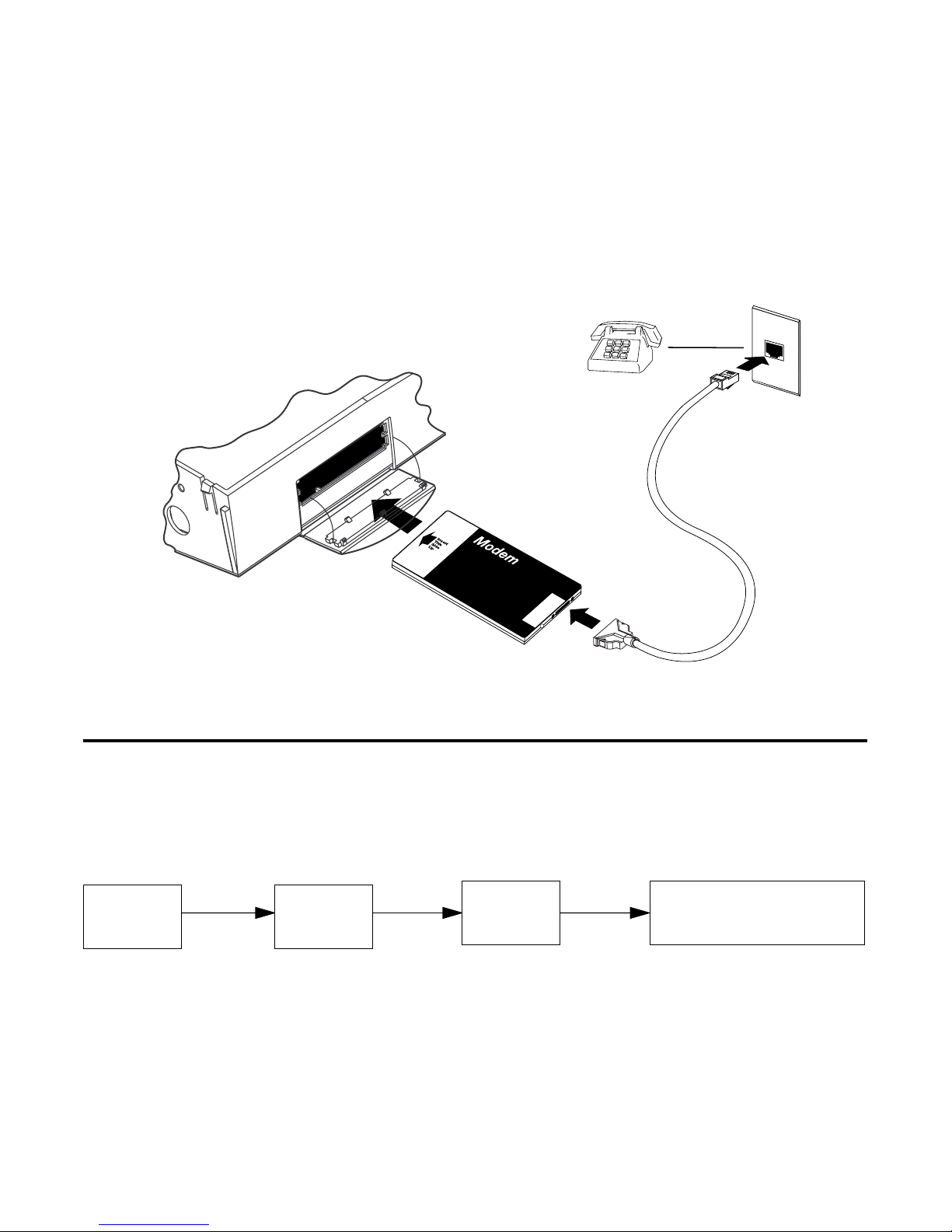
Connecting a modem to the PC Card port
The Netopia ISDN Router has a PC Card port (also known as a
PCMCIA card port) for attaching a PC Card Type II modem. The port
has two Type II slots and is located on the router’s left side behind a
pull-down cover.
Page 12

Introduction 1-5
You may want to attach a PC Card modem to the Netopia ISDN Router
to remotely configure it or to upgrade its firmware (see “To update
Netopia’s firmware” on page 10-17.)
Follow the manufacturer’s instructions when unpacking and preparing
to use the PC Card modem. A telephone cable should be included with
your modem. One end of the cable connects to your modem, while the
PC Card
(PCMCIA)
other end (RJ-11) connects to an analog telephone line wall socket
(
not
an ISDN line)
.
Page 13
1-6 Netopia ISDN Router Reference Guide
To attach the modem to the Netopia ISDN Router, pull down the door
that covers its PC Card slots and insert the modem. You can use
either slot.
Inserting a PC Card (PCMCIA) modem into the exposed PC Card slot.
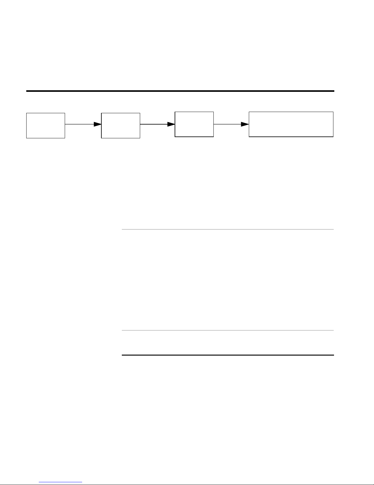
Navigating through the Advanced Configuration screens
To help you find your way to particular screens, some sections in this
guide begin with a graphical path guide similar to the following
example:
Main
Menu
Advanced
Config.
WAN
Setup
This particular path guide shows how to get to the WAN Setup
screens. The path guide represents these steps:
1. Beginning in the Main Menu, select the
item and press Return.
• ISDN Line Config.
• Connection Profiles
• Answer Profile
Advanced Configuration
Page 14

Introduction 1-7
2. Select the
W AN Setup
item in the Advanced Configuration screen
and press Return.
3. Select the
Answer Profile
ISDN Line Configuration, Connection Profiles
item in the WAN Setup screen and press Return.
To go back in this sequence of screens, use the Escape key.
, or
Page 15

1-8 Netopia ISDN Router Reference Guide
Keyboard navigation
Use your keyboard to navigate the Netopia ISDN Router’s
configuration screens, enter and edit information, and make choices.
The following table lists the navigation keys.
To... Use These Keys...
Move through selectable items in a
screen or pop-up menu
Execute action of a selected item or
open a pop-up menu of options for a
selected item
Change a toggle value
(Yes/No, On/Off)
Restore an entry or toggle value to
its previous value
Move one item up Ctrl + K
Move one item down Ctrl + J
Dump the device event log Ctrl + E
Dump the ISDN event log Ctrl + F
Refresh the screen Ctrl + L
Go to topmost selectable item <
Up, Down, Left, and
Right Arrow
Return or Enter
Tab
Esc
Go to bottom right selectable item >
Page 16

Chapter 2
Configuring ISDN Connections
This chapter shows you how to configure the Netopia ISDN Router to
make and receive network connections over its ISDN line, and how
to control those connections. There are five main sections:
■
“WAN setup,” beginning on page 2-2 shows you how to
configure your ISDN line and set up profiles for outgoing and
incoming calls.
2-1
■
“Answering calls,” beginning on page 2-26, shows you how to
set up an answer profile for incoming calls.
■
“WAN IP Address Serving,” beginning on page 2-33, discusses
how to configure the router to allocate an IP address to callers
from an address pool.
■
“Scheduled connections,” beginning on page 2-34 shows you
how to control the dates and times when connection profiles
can be used.
■
“Manually establishing connections,” beginning on page 2-40
and “Manually disconnecting connections,” beginning on
page 2-41 show you how to manually establish and disconnect
connections.
Page 17
2-2 Netopia ISDN Router Reference Guide
WAN setup
Main
Menu
Advanced
Config.
WAN
Setup
• ISDN Line Config.
• Connection Profiles
• Default Answer Profile
The WAN Setup screen has three subscreens, each involving a
different aspect of using the ISDN line to control connections to
remote IP or IPX networks.
Note: If you have completed Easy Setup (see the
Getting Started
guide), you will see the information you have already entered appear
in some of the WAN Setup subscreens.
To go to the WAN Setup screen, select WAN Setup in the Advanced
Configuration screen.
WAN Setup
ISDN Line Configuration...
Connection Profiles...
Default Answer Profile...
Return/Enter to configure Switch Type, SPIDs, and Directory Numbers.
From here you will configure yours and the remote sites' WAN
information.
ISDN line configuration
Enter the information provided by your ISDN service provider in the
ISDN Line Configuration screen.
To go to the ISDN Line Configuration screen, select ISDN Line
Configuration in the WAN Setup screen.
Page 18

Configuring ISDN Connections 2-3
Note: If your ISDN Line Configuration screen contains items that
are not discussed in this section, such as SPIDs, see Appendix D,
“ISDN Configuration Guide.”
North American models ISDN Line Configuration
+------------------------+
+------------------------+
Switch Type... | National ISDN-1 (NI-1) |
| AT&T 5ESS Pt-to-Pt |
SPID 1: | AT&T 5ESS Multipoint |
SPID 2: | Nortel DMS100 Custom |
+------------------------+
Directory Number 1:
Directory Number 2:
■ Select the Switch Type pop-up menu. The Switch Type pop-up
menu contains a list of North American specific switch
protocols. Each item in the list shows the associated switch
type and protocol. Choose the type of switch protocol your
telephone company uses.
Note: The switch type determines whether or not the SPID
fields will appear. On an AT&T point-to-point link, no SPID fields
will apprear.
National ISDN-1 (NI-1) can be used on an AT&T as well as a
Nortel DMS-100 Custom.
Page 19

2-4 Netopia ISDN Router Reference Guide
The selection you make determines the date and time format used
by the Netopia ISDN Router. Generally, the date and time format
used will be appropriate for your country. For more information, see
Appendix B, “Date and Time Formats.”
■ Select SPID 1 enter the primary SPID number exactly as
provided by the telephone company, and press the Return key.
If you did not receive a SPID (AT&T 5ESS custom point-to-point
switches have no SPID), skip this step.
If you have a second SPID, select SPID 2. Enter the secondary
SPID number and press the Return key.
Note: Note: If you experience problems related to using SPIDs,
also review Appendix A, “Troubleshooting.”
■ Select Directory Number 1, enter the primary directory number,
and press the Return key. Enter the number just as you would
dial it, including any required prefixes (such as area, access,
and long distance dialing codes).
■ If you have a second directory number, select Directory
Number 2. Enter the secondary directory number and press the
Return key. Enter the number just as you would dial it, including
any required prefixes (such as area, access, and long distance
dialing codes).
Note: In order for the changes that you have entered in the
ISDN Line Configuration screen to take effect, you must reset
the Netopia ISDN Router. Press the escape key to return to the
Main Menu. Select Statistics, Utilities, Tests and then select
Reset System.
Page 20

Configuring ISDN Connections 2-5
Non-North American
models
ISDN Line Configuration
Switch Type... Generic - EuroISDN
Directory Number 1:
Directory Number 2:
■ Select the Switch Type pop-up menu. The Switch Type pop-up
menu contains a list of country-specific switch protocols. Each
item in the list shows the name of a country (or region) and an
associated switch protocol. If the default selection corresponds
to the country in which the Netopia ISDN router is being
installed, do not change it. Otherwise, choose the type of
switch protocol your telephone company uses. The Generic -
EuroISDN protocol may be appropriate for countries not
appearing in the list.
Note: If the Netopia ISDN Router is being installed in Germany
or North America (the United States and Canada), make sure
that the correct protocol is selected. The Switch Type pop-up
menu contains more than one choice for Germany. Choose
Germany - EuroISDN unless your ISDN service provider advises
you to use the Germany - 1TR6 protocol.
The selection you make determines the date and time formats
used by the Netopia ISDN Router. Generally, the date and time
format used will be appropriate for your country. For more
information, see Appendix B, “Date and Time Formats.”
Page 21

2-6 Netopia ISDN Router Reference Guide
+-------------------------------------+
+--------------..more..---------------+
Switch Type... | France - EuroISDN| |
| Generic - EuroISDN | |
| Germany - EuroISDN |
| Germany - 1TR6 |
| Ireland - EuroISDN |
Directory Number 1: | Italy - EuroISDN |
Directory Number 2: | Japan - NTT |
| Luxembourg - EuroISDN | |
| Netherlands - EuroISDN |
| Norway - EuroISDN |
| Portugal - EuroISDN |
| Spain - EuroISDN |
| Sweden - EuroISDN |
| Switzerland - EuroISDN |
| United Kingdom - EuroISDN |
+-------------------------------------+
ISDN Line Configuration
Use up or down arrow keys to move among items. Use < or > keys to page.
■ Select Directory Number 1, enter the primary directory number,
and press the Return key. Enter the number just as you would
dial it, including any required prefixes (such as area, access,
and long distance dialing codes).
■ If you have a second directory number, select Directory
Number 2. Enter the secondary directory number and press the
Return key. Enter the number just as you would dial it, including
any required prefixes (such as area, access, and long distance
dialing codes).
Page 22

Configuring ISDN Connections 2-7
Connection profiles
A connection profile is a set of parameters that tells the Netopia
ISDN Router how to connect to a remote destination. Connection
profiles are also used to make out-bound calls and optionally to help
answer calls.
Small Office Models The Netopia ISDN Router Small Office models support up to 4
different connection profiles.
Corporate Models The Netopia ISDN Router Corporate models support up to 16
different connection profiles.
Each connection profile you set up allows the Netopia ISDN Router
to connect your network to another network that also has an ISDN
line and uses IP or IPX over the Point-to-Point Protocol (PPP).
To go to the Connection Profiles screen, select Connection Profiles
in the WAN Setup screen.
Connection Profiles
Display Connection Profiles...
Add Connection Profile...
Change Connection Profile...
Delete Connection Profile...
Establish Connection...
Return/Enter to see the list of currently defined Connection Profiles.
This Screen is the main point of navigation for Connection Profiles.
Page 23

2-8 Netopia ISDN Router Reference Guide
Displaying connection profiles
To display a view-only table of connection profiles, select Display
Connection Profiles in the Connection Profiles screen.
+-Profile Name---------------------IP Address----IPX Network-+
+------------------------------------------------------------+
| Easy Setup Profile |
| |
|
| |
| |
+------------------------------------------------------------+
Connection Profiles
To Dismiss list, hit Return/Enter.
The Connection Profiles table is a handy way to quickly see the
names and destination IP or IPX addresses of your connection
profiles.
Page 24

Configuring ISDN Connections 2-9
Adding a connection profile
To add a new connection profile, select Add Connection Profile in
the Connection Profiles screen.
Add Connection Profile
Profile Name: Profile 03
Profile Enabled: Yes
IP Enabled: Yes
IP Profile Parameters...
IPX Enabled: No
Initial naming and
activation of the
connection profile
IP configuration
parameters
Number to Dial:
Optional 2nd Number to Dial:
PPP/MP Options...
Telco Options...
Calling Number:
ADD PROFILE NOW CANCEL
■ Select Profile Name. Enter a name for the profile. For example,
if this profile is for connecting to an Internet Service Provider
(ISP), you may want to enter the ISP’s name here.
■ Select Profile Enabled and toggle it to Yes to activate the
profile.
■ Select IP Enabled and toggle it to yes or no depending on
whether you will be using TCP/IP over your ISDN connection.
This is the most common usage, and TCP/IP is required for an
Internet connection.
Page 25

2-10 Netopia ISDN Router Reference Guide
■ Select IP Profile Parameters. This is only available as an option
if IP Enabled is toggled to Yes.
Remote IP Address: 0.0.0.0
Remote IP Mask: 0.0.0.0
Address Translation Enabled: No
Filter Set...
Remove Filter Set
Receive RIP: No
IP Profile Parameters
■ Select Remote IP Address and enter the IP address of the
network being called.
Do not use an address already in use by
another connection profile.
Note: You may leave the address zero if you do not yet know
the address of the other network. The address should either be
provided by them or you can configure the Netopia ISDN Router
to provide the address from the IP Address Serving pool (see
“WAN IP Address Serving,” beginning on page 2-33. The latter
option is appropriate when the other network is an ISDN
modem or terminal adapter, or a Netopia ISDN Router using the
NAT (Network Address Translation ) feature set. See Chapter 5
in the Getting Started guide for more information on NAT.
■ Select Remote IP Mask and enter the IP mask used by the
remote network. Y ou may leave this zero if you will be assigning
a host IP address to the remote network using the method
described in step 5)
Small Office models ■ Select Address Translation Enabled. This option’s behavior will
be configured later in IP Setup in the Network Protocols Setup
section of Advanced Configuration. For more details, see
Chapter 4. IP Setup IP Network Address Translation (NAT, also
Page 26

Configuring ISDN Connections 2-11
referred to as IP Proxy).
■ Select Filter Set and then select an appropriate filter set from
the list. If you do not want to block any TCP/IP traffic, then
leave this entry blank. To define an additional filter set,see the
Filter Sets (Firewalls) section of this chapter.
Corporate Models ■ Select Receive RIP and toggle it to Yes (on) if you want the
Netopia to receive RIP information sent by remote routers that
are connected to your local area network (LAN).
Corporate Models ■ Hit Escape when you are finished configuring IP Profile
Parameters to go back to the Add Connection Profile screen.
The next section desribes how to configure the IPX parameters.
If you do not wish to enable IPX , skip to “Setting up Number to
Dial,” beginning on page 2-14.
Corporate Models
IPX configuration
parameters
■ Select Transmit RIP and toggle to Yes, if you want the Netopia
ISDN Router to send RIP information to remote routers that are
connected to your local area network (LAN)
■ From the Add Connection Profile screen select IPX Enabled and
toggle it to Yes or No depending on whether you will be using
IPX over your ISDN connection.
The IPX protocol is required to
use with other remote networks using IPX for an Intranet
connection. For more information on IPX, refer to Chapter 5,
“IPX Setup” of this Reference Guide.
Page 27

2-12 Netopia ISDN Router Reference Guide
Add Connection Profile
Profile Name: Profile 02
Profile Enabled: Yes
IP Enabled: Yes
IP Profile Parameters...
IPX Enabled: Yes
IPX Profile Parameters..
Number to Dial:
Optional 2nd Number to Dial:
PPP/MP Options...
Telco Options...
Calling Number:
ADD PROFILE NOW CANCEL
Return/Enter goes to new screen.
Configure a new Conn. Profile. Finished?
Page 28

Configuring ISDN Connections 2-13
■ Select IPX Profile Parameters. This is only available as an
option if IPX Enabled is toggled to Yes.
IPX Profile Parameters
Remote IPX Network: 00000000
Path Delay: 10
NetBios Packet Forwarding: Off
Incoming Packet Filter Set... <<NONE>>
Outgoing Packet Filter Set... <<NONE>>
Incoming SAP Filter Set... <<NONE>>
Outgoing SAP Filter Set... <<NONE>>
Periodic RIP Timer: 60
Periodic SAP Timer: 60
Configure IPX requirements for a remote network connection here.
■ Select Remote IPX Network (optional) and enter the network
address of the IPX network being called.
already in use by another connection profile.
Do not use an address
If this value is set
to zero and the Netopia is answering a call, the remote address
will be learned when the profile is active.
Note: Unlike IP, the IPX network address is never used in
matching a profile when answering a non-authenticated call.
Note: This value must be non-zero for the Netopia ISDN Router
to be able to initiate a demand connections through this profile.
■ To change the default Path Delay, select and enter a value (in
ticks; a tick is equivalent to 1/18 sec).
Page 29

2-14 Netopia ISDN Router Reference Guide
■ To enable NetBIOS Packet Forwarding, toggle the selection to
Yes.
■ Select Incoming Packet Filter Set, to attach a filter set for
filtering incoming packets and choose a filter set from the list.
■ Select Outgoing Packet Filter Set, to attach a filter set for
filtering outgoing packets and choose a filter set from the list.
■ Select Incoming SAP Filter Set,to attach a filter set for filtering
server entries within incoming Service Advertising Protocol
(SAP) packets and choose a filter set from the list.
■ Select Outgoing SAP Filter Set,to attach a filter set for filtering
server entries within outgoing Service Advertising Protocol
(SAP) packets and choose a filter set from the list.
■ Select Periodic RIP Timer, and enter a new value (in seconds)
to change the periodic RIP timers default value.
■ Select Periodic SAP Timer, and enter a new value (in seconds)
to change the periodic SAP timers default value.
■ Hit Escape to go back to the Add Connection Profile screen
when you are finished configuring IPX Profile Parameters.
For more information on creating an IPX filter set, go back to the
Advanced Configuration screen and select the Filter Sets (Firewalls)
screen. Also refer to Chapter 6. IPX Setup.
Setting up Number to Dial ■ Select Number to Dial and enter the directory number (the
number of the ISDN line) of the network being called.
Setting up authentication ■ Select PPP/MP Options and go to the PPP/MP Options screen.
Point-to-Point Protocol (PPP) and Multilink Point-to-Point Protocol
(MP) allow the Netopia ISDN Router to make adaptable and
Page 30

Configuring ISDN Connections 2-15
secure connections to other networks.
PPP/MP Options
Send Authentication... PAP
Send User Name:
Send Password:
Receive User Name:
Receive Password:
B-Channel Usage... Dynamic
Data Compression... LZS
Return/Enter for no security, PAP (password clear text), CHAP (encrypted).
In this Screen you will configure the PPP/MP specific connection params.
■ Select the Send Authentication pop-up menu and choose the
type of connection security supported by the network being
called. This should be PAP, CHAP, or None (if the remote
network does not use PAP or CHAP). If you choose PAP or
CHAP, two (2) “send” and two (2) “receive” items appear below
the Send Authentication pop-up menu. On the Netopia ISDN
Router the default authentication is set for PAP, as this is
usually the most popular security parameter that ISP’s (Internet
Service Providers) and other remote networks (set up for a
point-to-point connection) use.
Note: If you choose None, and the remote network expects to
connect to the Netopia ISDN Router using this connection
profile, you may need to set the answer profile to accept calls
using no authentication (None). See “Answering calls” on
page 2-26.
Page 31

2-16 Netopia ISDN Router Reference Guide
■ If you choose to use PAP for calling the remote network, you
will need to obtain a name and password from the remote
network’s administrator. Enter the name in Send User Name
and enter the password in Send Password. If you choose PAP,
and you want the remote network to use this connection profile
when it calls the Netopia ISDN Router, select Receive Name
and enter a name. Select Receive Password and enter a
password. You will need to give this name and password to the
remote network’s administrator.
Note: If you choose PAP, and the remote network expects to
connect to the Netopia ISDN Router using this connection
profile, you may need to set the answer profile to accept calls
using PAP. See “Answering calls” on page 2-26.
■ If you choose to use CHAP for calling the remote network,
obtain a name and secret (the CHAP term for password) from
the remote network’s administrator. Enter the name in Send
Host Name and enter the password in Send Secret. If you
choose CHAP, and you want the remote network to use this
connection profile when it calls the Netopia ISDN Router, select
Receive Host Name and enter a name. Select Receive Secret
and enter a secret. You will need to give this name and secret
to the remote network’s administrator.
Note: If you choose CHAP, and the remote network expects to
connect to the Netopia ISDN Router using this connection
profile, you may need to set the answer profile to accept calls
using CHAP. See “Answering calls” on page 2-26.
Page 32

Configuring ISDN Connections 2-17
PPP/MP Options
Send Authentication... PAP
Send User Name:
Send Password:
Receive User Name:
Receive Password: +-------------------+
+-------------------+
B-Channel Usage... | Dynamic |
| 1 B-Channel |
Data Compression... | 2 B-Channels |
| 2 B, Pre-emptable |
+-------------------+
1 or 2 B-Channels will be used, depending on traffic volume.
Other PPP/MP options
4. Select B-Channel Usage and choose how this connection
profile will use the ISDN line’s B channels. Choose:
■ Dynamic ( default setting), to allow calls to use the two B
channels in a dynamic manner. This option allows the
connection profile to use one or both channels at any time
during a call. The decision to alternately use or drop the second
B channel is based on an algorithm that looks at traffic volume
over time. With Dynamic, one B channel may be relinquished to
accept an incoming call through or when a second connection
profile is used to make a call. See Appendix D for information
on “Dynamic B-channel usage” on page D-4 for more
information.
Note: To relinquish the B channel for an incoming call requires
telco provisioning of ACO (Additional Call Offering).
■ 1 B-Channel to force a call to remain within one B channel.
(Throughput will generally be at either 56k or 64k, depending on how the local telephone company installs your ISDN
Page 33

2-18 Netopia ISDN Router Reference Guide
line. This will also depend on certain geographic locations
in North America. The standard ISDN data rate outisde of
North America is 64K. )
■ 2 B-Channels to force a call to use both B channels.
(Throughput connection will generally run at 128k.)
■ 2 B Pre-emptable to allow calls to use the 2B channels in
a dynamic, pre-emptable manner. This option is very similar to Dynamic, in that the second B channel may be relinquished to accept an incoming call or to initiate a second
outgoing call. However, 2B Pre-emptable will always try to
add a second B channel to the call when the second channel is otherwise unused, much like a fixed 2 B channel
selection.
PPP/MP Options
Send Authentication... PAP
Send User Name:
Send Password:
Receive User Name:
Receive Password:
B-Channel Usage... +--------------+
+--------------+
Data Compression... | None |
| Ascend LZS |
| Standard LZS |
+--------------+
■ Select Data Compression and choose the type of data
compression to use:
■ None to use no compression.
Page 34

Configuring ISDN Connections 2-19
■ Ascend LZS to use compression that is compatible with
the type used by Ascend Communications
. This is the
default setting as most ISP’s (Internet Service Providers)
and remote networks use Ascend’s proprietary data compression utility.
■ Standard LZS to use IETF standard LZS data compression.
Note: Using data compression can substantially increase your
ISDN line’s throughput, resulting in noticeably improved
performance for desktop communications applications.
However, if the remote network does not or cannot enable LZS
compression, the Netopia ISDN Router will not be able to use
Stac compression either, regardless of the Data Compression
parameter’s setting.
You are now finished configuring the PPP options. Return to the
Add Connection Profile screen to continue. You can navigate
back to this screen by pressing the escape key.
Dialing and call options ■ Select Telco Options and hit return to go to the Telco Options
screen. The T elco Options screen contains items that allow you
to control the calls made on the ISDN line with this particular
Page 35

2-20 Netopia ISDN Router Reference Guide
connection profile.
Dial... Dial In/Out
Dial On Demand: Yes
Initiate Data Service... 64 kb/sec
Callback: No
Idle Timeout (seconds): 300
Return/Enter to allow dialing out, dialing in, or both. In this Screen
you configure options for the way you will establish a link.
Telco Options
■ Select Dial and decide whether this connection profile will only
make calls, only receive calls, or do both. Choose from In Only
(receive calls), Out Only (make calls), or Dial In/Out (receive
and make calls).
■ Select Dial On Demand and toggle it to No to only be able to
make manual connections with this profile. The default for Dial
On Demand is Yes, which is correct for most uses. When Dial
On Demand is set to Yes, it allows the Netopia ISDN Router to
automatically make calls as the need arises, such as when a
request to connect to a host on the Internet is made by a
computer on the local network. Dial on demand also comes into
action when IP and/or IPX traffic needs to go to a route defined
by the profile attributes. Every dial on demand profile becomes
a part of the routing table. For more information see “Manually
establishing connections” on page 2-40 for more information
about manual connections.
Page 36

Configuring ISDN Connections 2-21
Telco Options
Dial... Dial In/Out
Dial On Demand: +-----------+
+-----------+
Initiate Data Service... | 64 kb/sec |
| 56 kb/sec |
Callback: | Speech |
+-----------+
Idle Timeout (seconds): 300
■ Select Initiate Data Service and choose the correct ISDN
bandwidth to use with this connection profile. In North America,
user’s are not guaranteed of having a 64k connection to their
destination; only when 64k is not available from point A to point
B should 56k be selected. The Router auto falls back to 56k
when 64k service is not available. It is advised to select 56k
when you know that the 64k service will fail. You may also
select Speech if your line is provisioned for this feature and the
call is within you local ISDN region. This may allow users to
save money, but is not guaranteed to work outside of their
switch.
■ 56K and 64K are data grade bearer capabilities. Speech is a
bearer capability that tells the telco network that the call will be
used for voice purposes. The telco network may apply echo
cancellation, compression, and other schemes that are not
appropriate for data. In addition, Netopia ISDN Router calls are
data-only; speech will not allow the Netopia to dial an analog
device.
■ Select Callback and toggle to Yes to drop incoming calls (calls
that the Netopia ISDN Router answers) and use this connection
profile to call the remote network back. (See “Answering calls”
Page 37

2-22 Netopia ISDN Router Reference Guide
on page 2-26 or “Calling number authentication (CNA)” on
page 7-6 for more information on incoming calls matching
connection profiles). The default for Callback is No.
■ Select Idle Timeout and set the time the Netopia ISDN Router
will wait before dropping a call if there is no activity on the line.
Note: The default timeout setting is 300 seconds.
You are now done configuring the Telco options. Press the
escape key to return to the Add Connection Profile screen.
Add Connection Profile
Profile Name: Profile 03
Profile Enabled: Yes
IP Enabled: Yes
IP Profile Parameters...
IPX Enabled: No
Number to Dial:
Optional 2nd Number to Dial:
PPP/MP Options...
Telco Options...
Calling Number:
ADD PROFILE NOW CANCEL
Enter the calling directory number if you want to match with CNA.
Configure a new Conn. Profile. Finished? ADD or CANCEL to exit.
■ Select Calling Number... and enter the telephone number that
your Netopia will match to incoming calls. Question marks “?”
can be used in place of numbers as wild card characters to
ensure that matches are made on different directory numbers.
Page 38

Configuring ISDN Connections 2-23
You are now done configuring the dialing and call options.
■ Select ADD PROFILE NOW to save the current connection
profile, and press return to go to the Connection Profiles
screen. You also have the option to select CANCEL to exit the
Add Connection Profile screen without saving the new profile.
Modifying a Connection Profile
To modify a connection profile, select Change Connection Profile in
the Connection Profiles screen to display a table of connection
profiles.
Select a connection profile from the table and go to the Change
Connection Profile screen. The parameters in this screen are the
same as the ones in the Add Connection Profile screen. To find out
how to set them, see “Adding a connection profile” on page 2-9.
Change Connection Profile
Profile Name: Profile 01
Profile Enabled: Yes
IP Enabled: Yes
IP Profile Parameters...
IPX Enabled: Yes
IPX Profile Parameters..
Number to Dial:
Optional 2nd Number to Dial:
PPP/MP Options...
Telco Options...
Calling Number:
Return accepts * ESC cancels * Left/Right moves insertion point * Del deletes.
Modify Connection Profile here. Changes are immediate.
Page 39

2-24 Netopia ISDN Router Reference Guide
Deleting a connection profile
To delete a connection profile, select Delete Connection Profile in
the Connection Profiles screen to display a table of connection
profiles.
Select a connection profile from the table and press the Return key
to delete it. To exit the table without deleting the selected
connection profile, press the Escape key.
+-Profile Name---------------------IP Address----IPX Network-+
+------------------------------------------------------------+
| Alameda CA 163.176.52.130 |
| |
| |
| |
| |
| |
| |
| |
+------------------------------------------------------------+
Up/Down Arrow Keys to select, ESC to cancel, Return/Enter to Delete.
Establishing a Connection
To establish a connection , select Establish Connection in the
Connection Profiles screen to display a table of connection profiles.
Page 40

Configuring ISDN Connections 2-25
Select the desired connection profile and hit return. The following
screen will appear.
Call Status
Profile Name -- Alameda CA
Connection State -- Dialing...
Channel B1 State --
Channel B2 State --
Once the established ISDN call connects to the remote network or
Internet Service Provider, a message appears indicating what rate
the connection is communicating. The diagram below indicates the
Netopia ISDN Router is able to connect to the
Alameda CA
remote
LAN on 2B channels.
Call Status
Profile Name -- Alameda CA
Connection State -- Connected.
Channel B1 State -- Up
Channel B2 State -- Up
Hit ESCAPE/RETURN/ENTER to return to previous menu.
Page 41

2-26 Netopia ISDN Router Reference Guide
Answering calls
Netopia can answer calls as well as initiate them. To answer calls,
Netopia uses an answer profile, just as it uses a connection profile
to make calls. Netopia’s answer profile controls how incoming calls
are set up, authenticated, filtered, and more.
How the answer profile works
The answer profile works like a guard booth at the gate to your
network: it only scrutinizes incoming calls. Like the guard booth, the
answer profile allows calls based on a set of criteria that you define.
The main criterion used to check calls is whether they match one of
the connection profiles already defined. If PAP or CHAP
authentication is being used, the answer profile checks that the
incoming call’s name and password/secret match the receive name
and password/secret of a connection profile. If PAP or CHAP are not
being used, an incoming call is matched to a connection profile
using the remote network’s IP address (that is, the caller is defined
as the destination of a particular connection profile).
You could instruct the answer profile to allow calls in even if they fail
to match a connection profile. Continuing the guard booth analogy,
this would be like removing the guards or having them wave all calls
in, regardless of their source.
If an incoming call is matched to an existing connection profile, the
call is accepted. All of that connection profile’s parameters, except
for authentication, are adopted for the call.
If an incoming call is not required to match a connection profile, and
fails to do so, it is accepted as a standard IP connection. Accepted,
unmatched calls adopt the call parameter values set in the answer
profile (see below).
Page 42

Configuring ISDN Connections 2-27
Customizing the default answer profile
You can customize the Netopia ISDN Router’s default answer profile
in the Default Answer Profile screen. To go to the Default Answer
Profile screen, select Default Answer Profile in the WAN Setup
screen.
WAN Setup
ISDN Line Configuration...
Connection Profiles...
Default Answer Profile...
Return/Enter to configure info about the remote site(s).
From here you will configure yours and the remote sites' WAN information.
Default Answer Profile
Calling Number Authentication... Ignored
Must Match a Defined Profile: Yes
Data Compression... Ascend LZS
Idle Timeout: 300
IP Enabled: Yes
IP Parameters...
IPX Enabled: Yes
IPX Parameters...
Configure values which may be used when receiving a call in this screen.
■ Select Calling Number Authentication... in the Default Answer
Page 43

2-28 Netopia ISDN Router Reference Guide
Profile screen and choose one of the following settings:
Ignored: Calling Number Authentication (CNA) is not in effect. This
is the default setting.
Preferred: Authentications is attempted if the calling number is
available. If authentication fails, or the calling number is not
available, the call proceeds as usual and the caller may still connect
successfully. Use this setting if you expect to receive both regular
and CNA-authenticated calls.
Required: Authentication is attempted if the calling number is
available. If authentication fails, or the calling number is not
available, the Netopia ISDN Router disconnects the caller. Use this
setting if you require all calls to be CNA-authenticated.
+-----------+
Calling Number Authentication... | Ignored |
| Preferred |
| Required |
Must Match a Defined Profile: +-----------+
Default Answer Profile
Data Compression... Ascend LZS
B-Channel Usage... Dynamic
Idle Timeout: 300
IP Enabled: Yes
IP Parameters...
IPX Enabled: Yes
IPX Parameters...
This setting requires that the calling number match a profile to
answer.
Page 44

Configuring ISDN Connections 2-29
Calling Number Authentication (CNA), is an application of caller ID.
It is a method of verifying that an incoming call is originating from an
expected site. Using CNA, you can increase the security of your
network by requiring that callers not only possess the correct PAP or
CHAP information, but also that they are calling from a particular
physical location. CNA should be available where caller ID services
are available, but you will need to consult with your ISDN service
provider to find out if your ISDN line is provisioned for caller ID.
CNA works by checking the calling number that the Netopia ISDN
Router receives during the initial setup phase of an incoming call
against the stored Calling Number defined in each connection
profile. When a match occurs, the incoming call is handled by the
connection profile containing the matched number.
Using CNA can also provide cost saving because calls are not billed
during the CNA phase. With CNA, a caller can set up a connection to
the Netopia ISDN Router without incurring any charges by accessing
a dial-back connection profile. If the callers rates are higher than
those charged to the Netopia ISDN Routers return call, then using
CNA has saved the difference.
Page 45

2-30 Netopia ISDN Router Reference Guide
Configuring profiles for incoming calls.
If the answer profile must
match...
To force incoming calls to match connection profiles, select Must
Match a Defined Profile and toggle it to Yes. Incoming calls that
cannot be matched to a connection profile are dropped. To allow
unmatched calls to be accepted as standard IP or IPX connections,
toggle Must Match a Defined Profile to No.
Note: If Must Match a Defined Profile is set to Yes, the items
below it will not appear.
If Must Match a Defined Profile is set to Yes, the answer profile
only accepts calls that use the same authentication method defined
in the Authentication item. If PAP or CHAP are involved, the caller
must have a name and password or secret that match one of the
connection profiles. The caller must obtain these from you or your
network administrator before initiating the call.
For example, if Must Match a Defined Profile is set to Yes, and
Authentication is set to PAP, then only incoming calls that use PAP
and match a connection profile will be accepted by the answer
profile.
Note: If authentication in the default answer profile is set to CHAP,
the value of the CHAP Challenge Name item must be identical to
the value of the Send Host Name item of the connection profile to
be matched by the caller.
If the answer profile
doesn’t have to match...
If Must Match a Defined Profile is set to No, Authentication is
assumed to be None, even if you’ve set it to PAP or CHAP. The
answer profile uses the caller’s IP address to match a connection
profile. However, the answer profile cannot discover a caller’s
subnet mask; it assumes that the caller is
address:
■ Class A addresses are assumed to have a mask of 255.0.0.0
■ Class B addresses are assumed to have a mask of
■ Class C addresses are assumed to have a mask of
not
subnetting its IP
255.255.0.0
255.255.255.0. Class C address ranges are generally the
Page 46

Configuring ISDN Connections 2-31
most common subnet allocated.
If a remote network has a non-standard mask (that is, it uses
subnetting), the only way for it to successfully connect to the
Netopia ISDN Router is by matching a connection profile. In other
words, you will have to set up a connection profile for that network.
The answer profile’s
default parameters
Non-North American
models only
You can set the following default parameters for incoming calls:
■ Authentication
■ Force 56K on Answer
■ LZS Data Compression
If Must Match a Defined Profile is set to No, you can also set the
following parameters for accepted calls that do not match a
connection profile:
■ B-Channel Usage
■ Idle Timeout
■ Filter Set
All of these parameters are similar to the connection profile
parameters of the same names. To find out how to set them, see
“Adding a connection profile” on page 2-9.
Call acceptance scenarios
The following are a few common call acceptance scenarios and
information on how to configure the router for those purposes.
■ To accept all calls, regardless of whether they match a
connection profile:
■ Toggle Must Match a Defined Profile to No.
■ T o only accept calls that match a connection profile through use
of a name and password (or secret):
■ Toggle Must Match a Defined Profile to Yes,
and
Page 47

2-32 Netopia ISDN Router Reference Guide
■ Set Authentication to PAP or CHAP.
Note: The authentication method you choose determines which
connection profiles are accessible to callers. For example, if you
choose PAP, callers using CHAP or no authentication will be
dropped by the answer profile.
■ To allow calls that
only
match a connection profile’s remote
IPand/or IPX address:
■ Toggle Must Match a Defined Profile to Yes,
■ set Authentication to None.
■ To not allow
any
incoming calls to connect to the Netopia ISDN
and
Router:
■ Toggle Must Match a Defined Profile to Yes,
■ Set the Dial option in the Telco Options screen of every con-
and
nection profile to Dial Out Only
Page 48

WAN IP Address Serving
Configuring ISDN Connections 2-33
Main
Menu
Advanced
Config.
IP Address
Serving
Small Office models only A new feature has been added to the Netopia ISDN Router which is
called WAN IP Address Serving. The following definition applies:
WAN IP Address Serving is utilized when the Netopia ISDN Router
serves an IP address to an incoming call from a remote site. The
incoming caller can be either a TA (Terminal Adapter), such as the
Netopia ISDN Modem or another Netopia ISDN Router with the NAT
(Network Address Translation) feature set. The incoming caller will
dynamically obtain an IP address from a pool of IP addresses that the
Netopia ISDN Router serves.
The Netopia ISDN Router serving the IP address should have a
connection profile with an IP address of 0.0.0.0 defined for the calling
TA or Router.
IP Address Serving
IP Address Serving: On
Server Name is Netopia PN435
Return accepts * Tab toggles * ESC cancels.
Configure DHCP, BOOTP, WAN IP, and/or MacIP Address Serving here.
Page 49

2-34 Netopia ISDN Router Reference Guide
To select WAN IP Address Serving, go to the IP Address Serving
screen from the Advanced Configuration menu and toggle On.
Note: WAN IP Address Serving is used for
connections
information on how to use WAN IP Address Serving.
Scheduled connections
Main
Menu
Advanced
Config.
You can set the Netopia ISDN Router to make scheduled connections
using designated connection profiles. This is useful for creating and
controlling regularly scheduled periods when the router can be used
by hosts on your network. It is also useful for once-only connections
that you want to schedule in advance.
To go to the Scheduled Connections screen, select Scheduled
Connections in the Advanced Configuration screen.
only incoming caller
. Refer to “IP address serving” on page 4-18, for more
Scheduled
Connections
Return/Enter to display currently configured Scheduled Connections.
Navigate from here to add/modify/change/delete Scheduled Connections.
Scheduled Connections
Show Scheduled Connections...
Add Scheduled Connection...
Change Scheduled Connection...
Delete Scheduled Connection...
Page 50

Configuring ISDN Connections 2-35
Viewing scheduled connections
To display a table of view-only scheduled connections, select Show
Scheduled Connections in the Scheduled Connections screen. Each
scheduled connection occupies one row of the table.
Scheduled Connections
+-Days----Begin At---HH:MM---When----Conn. Prof. Name----Enabled-----+
+--------------------------------------------------------------------+
| mtWtfss 08:30PM 06:00 weekly Profile 01No|
| |
| |
| |
| |
| |
+--------------------------------------------------------------------+
The first column in the table shows a one-letter representation of the
Days of the week, from Monday (M or m) to Sunday (S or s). If a letter
representing a day is capitalized, the connection will be activated on
that day; a lower-case letter means that the connection will not be
activated on that day. If the scheduled connection is configured for a
once-only connection, the word “once” will appear instead of the days
of the week.
The other columns show:
■ The time of day that the connection will Begin At
■ The duration of the connection (HH:MM)
■ Whether it’s a recurring Weekly connection or used Once Only
■ Which connection profile (Conn. Prof.) is used to connect
■ Whether the scheduled connection is currently Enabled
You should make sure that the Netopia ISDN Router’s system date
and time are correct (see “Setting the system date and time” on
page 10-1). The router checks the date and time set in scheduled
connections against the system date and time.
Page 51

2-36 Netopia ISDN Router Reference Guide
Adding a scheduled connection
To add a new scheduled connection, select Add Scheduled
Connection in the Scheduled Connections screen and go to the Add
Scheduled Connection screen.
Scheduled Connection Enable: On
How Often... Weekly
Set Weekly Schedule...
Use Connection Profile...
Add Scheduled Connection
Setting days, times, and
duration with the
weekly schedule
ADD SCHEDULED CONNECTION CANCEL
Return accepts * Tab toggles * ESC cancels.
Scheduled Connections dial remote Networks on a Weekly or Once-Only
basis.
Follow these steps to configure the new scheduled connection:
■ To activate the connection, select Scheduled Connection Enable
and toggle it to On. You can make the scheduled connection
inactive by toggling Scheduled Connection Enable to Off.
■ Decide how often the connection should take place by selecting
How Often and choosing Weekly or Once Only from the pop-up
menu. The item directly below How Often allows you to set the
exact weekly schedule or once-only schedule. If How Often is set
to Weekly, the item directly below How Often reads Set Weekly
Schedule. If How Often is set to Once Only, the item directly
below How Often reads Set Once-Only Schedule.
■ If you set How Often to Weekly, select Set Weekly Schedule and
go to the Set Weekly Schedule screen. If you set How Often to
Once Only, skip to step 8.
Page 52

Configuring ISDN Connections 2-37
■ Select the days for the scheduled connection to occur and toggle
them to Yes.
Set Weekly Schedule
Monday: No
Tuesday: No
Wednesday: No
Thursday: No
Friday: No
Saturday: No
Sunday: No
Place Call At (Time): 04:15
AM or PM... AM
Call Duration: 00:00
Return accepts * Tab toggles * ESC cancels.
■ Select Place Call at and enter the time to initiate the scheduled
connection. Depending on the Switch Type setting, the Netopia
ISDN Router may be using the 12- or 24-hour clock (see Appendix
B, “Date and Time Formats”).
■ You must enter the time in the format H:M, where H is a one- or
two-digit number representing the hour and M is a one- or
two-digit number representing the minutes. The colon is
mandatory. For example, the entry 1:3 (or 1:03) would be
accepted as 3 minutes after one o’clock. The entry 7:0 (or 7:00)
would be accepted as seven o’clock, exactly. The entries 44, :5,
and 2: would be rejected.
■ Select AM or PM and choose AM or PM from the pop-up menu.
■ Select Call Duration (Hours:Minutes) and enter the maximum
duration allowed for this scheduled connection, per call.
You are done configuring the weekly options. Return to the Add
Scheduled Connection screen and skip to step 13 to continue.
Page 53

2-38 Netopia ISDN Router Reference Guide
Setting a date, time, and
duration with the
once-only schedule
■ If you set How Often to Once Only, select Set Once-Only
Schedule and go to the Set Once-Only Schedule screen.
Set Once-Only Schedule
Place Call On (Date): 10/19/1996
Place Call At (Time): 05:04
AM or PM... PM
Call Duration: 00:00
Depending on the Switch Type setting, the Netopia ISDN Router
may be using one of several date and time format combinations
(see Appendix B, “Date and Time Formats”).
■ Select Place Call On (Date) and enter a date in the format
MM/DD/YY or MM/DD/YYYY (month, day, year).
Note: You must enter the date in the format specified. The
slashes are mandatory. For example, the entry 5/1/95 would be
accepted as May 1, 1995. The entry 1/6 would be rejected.
■ Select Place Call at (Time) and enter the time to initiate the
scheduled connection.
Note: You must enter the time in the format H:M, where H is a
one- or two-digit number representing the hour and M is a one- or
two-digit number representing the minutes. The colon is
mandatory. For example, the entry 1:3 (or 1:03) would be
accepted as 3 minutes after one o’clock. The entry 7:0 (or 7:00)
would be accepted as seven o’clock, exactly. The entries 44, :5,
and 2: would be rejected.
■ Select AM or PM and choose AM or PM. The AM or PM item
appears only if the time is in the 12-hour clock format.
Page 54

Configuring ISDN Connections 2-39
■ Select Call Duration (Hours:Minutes) and enter the maximum
duration allowed for this scheduled connection. Use the same
format restrictions noted above.
■ You are done configuring the once-only options. Return to the Add
Scheduled Connection screen to continue.
■ In the Add Scheduled Connection screen, select Use Connection
Profile and choose from the list of connection profiles you have
already created. A scheduled connection must be associated with
a connection profile to be useful. The connection profile becomes
active during the times specified in the associated scheduled
connection, if any exists.
■ Select ADD SCHEDULED CONNECTION to save the current
scheduled connection. Select CANCEL to exit the Add Scheduled
Connection screen without saving the new scheduled connection.
Modifying a scheduled connection
To modify a scheduled connection, select Change Scheduled
Connection in the Scheduled Connections screen to display a table of
scheduled connections.
Select a scheduled connection from the table and go to the Change
Scheduled Connection screen. The parameters in this screen are the
same as the ones in the Add Scheduled Connection screen (except
that ADD SCHEDULED CONNECTION and CANCEL do not appear). To
find out how to set them, see “Adding a scheduled connection” on
page 2-36.
Deleting a scheduled connection
To delete a scheduled connection, select Delete Scheduled
Connection in the Scheduled Connections screen to display a table of
scheduled connections.
Select a scheduled connection from the table and press the Return
key to delete it. To exit the table without deleting the selected
scheduled connection, press the Escape key.
Page 55

2-40 Netopia ISDN Router Reference Guide
Manually establishing connections
Main
Menu
Statistics, Utilities, Tests
Establish Connection
Manually initiating a connection
To manually establish a connection, select Establish Connection in
the Connection Profiles screen to display a table of connection
profiles.
Select a connection profile, then press the Return key to initiate that
profile. Press the Escape key to exit without initiating a connection.
When connections are established in this way, a call progress
notification screen appears.
Call Status
Profile Name -- Profile On
Connection State -- Connected.
Channel B1 State -- Up
Channel B2 State -- Up
Hit ESCAPE/RETURN/ENTER to return to previous menu.
The information displayed is useful for diagnosing problems with
particular connection profiles.
Page 56

Manually disconnecting connections
Configuring ISDN Connections 2-41
Main
Menu
Statistics, Utilities, Tests
Disconnect
In the Disconnect screen, you can force the Netopia ISDN Router to
hang up a current ISDN or console connection.
To go to the Disconnect screen, select Disconnect in the Statistics,
Utilities, Tests screen.
Disconnect
-----------------------------WAN CONNECTIONS--------------------------Conn--Connection Profile Name----------Rem. IP Address--State-----% Use
clear
clear
The Disconnect screen displays a table, called WAN CONNECTIONS,
listing current B-channel connection information. Select the
connection to hang up and press the Return key. The selected
connection will be dropped and the word “clear” will appear in place of
the connection information.
The WAN CONNECTIONS table has the following columns:
Conn.: The B channel being used (number 1 or number 2). If no
connection exists on a B channel, the word “clear” appears as an
entry.
Connection Profile Name: The connection profile being used for this
connection.
Rem. IP Address: The remote site’s IP address.
Page 57

2-42 Netopia ISDN Router Reference Guide
State: The connection’s status. A connection’s status can be one of
the following:
■ B1 UP (first ISDN B channel is in use)
■ B2 UP (second ISDN B channel is in use)
■ B1 & B2 UP (both ISDN B channels are in use)
■ WAITING (a connection is in the process of beginning or ending)
% Use: The percentage of bandwidth used out of the total bandwidth
available
Disconnecting console sessions
Any time there is a console connection to the Netopia ISDN Router,
the item CONSOLE CONNECTION can appear below the WAN
CONNECTIONS table. This item allows you to end the active console
session. Any one of three possible selections may appear in
CONSOLE CONNECTION, each corresponding to the connection
method used:
■ HANG UP THIS TELNET CONSOLE SESSION NOW (telnet session
from another host)
■ HANG UP THIS PC CARD CONSOLE SESSION NOW (analog
telephone line dial-in session)
■ LOG OFF THIS CONSOLE SESSION NOW (console session
through the console port; only appears when you create user
accounts to restrict access to the console)
Page 58

Chapter 3
Connecting Your Local Network
In this chapter, you will learn how to physically connect the Netopia
ISDN Router to your local area network (LAN). Before you proceed,
make sure the Netopia ISDN Router is properly configured. You
should have configured the Router using Easy Setup or with custom
settings.
3-1
Overview
You can connect the Netopia ISDN Router to an IP or IPX network
that uses Ethernet. If you have a PC LAN using IP over Ethernet, you
can connect it to the Netopia ISDN Router’s Ethernet port. You can
also connect the Router to an AppleTalk network that uses either
Ethernet or LocalTalk.
AppleT alk networks based on Ethernet cabling (EtherTalk) connect to
all models of the Router through their Ethernet ports. Apple
Macintosh computers using native IP also connect to the Router’s
Ethernet port.
AppleTalk networks based on LocalTalk cabling connect to the 400
series models through their LocalTalk ports. If you have both kinds
of AppleTalk networks, you can connect one to the Netopia ISDN
Router’s LocalTalk port and the other to its Ethernet port. AppleT alk
traffic will be routed between these two networks.
Caution! Before connecting the Netopia ISDN Router to any AppleTalk LANs
that contain other AppleTalk routers, you should read “Routers and
seeding” in “AppleTalk Networks” on page 6-1.
See the sections later in this chapter for details on how to connect
the Netopia ISDN Router to the two types of networks.
Page 59

3-2 Netopia ISDN Router Reference Guide
Readying computers on your local network
PC and Macintosh computers must have certain components
installed before they can communicate through the Netopia ISDN
Router. The following illustration shows the minimal requirements
for a typical PC or Macintosh computer.
Application software
Ethernet/EtherTalk/LocalTalk
TCP/IP stack
Your PC
or Macintosh
computer
To the Netopia ISDN Router
Application software: This is the software you use to send e-mail,
browse the World Wide Web, read newsgroups, etc. These
applications may require some configuration. Examples include the
Eudora Light e-mail client, and the web browsers Microsoft’s
Internet Explorer and Netscape Navigator.
TCP/IP stack: This is the software that lets your PC or Macintosh
communicate using Internet protocols. TCP/IP stacks must be
configured with some of the same information you used to configure
the Netopia ISDN Router. There are a number of TCP/IP stacks
available for PC computers. Windows 95 includes a built-in TCP/IP
stack. Macintosh computers use either MacTCP or Open Transport.
Ethernet: Ethernet hardware and software drivers enable your PC or
Macintosh computer to communicate on the LAN.
EtherTalk: This is the AppleTalk protocol used over Ethernet.
Page 60

Connecting Your Local Network 3-3
Once the Netopia ISDN Router is properly configured and connected
to your LAN, PC and Macintosh computers that have their required
components in place will be able to connect to the Internet or other
remote IP networks.
Connecting to a LocalTalk network—for 400 series models
Connect one end of the LocalTalk cable to the Netopia ISDN
Router’s LocalTalk port. Connect the other end of the cable to your
LocalTalk network.
If your LocalTalk network is not based on standard PhoneNET
cabling, use the PhoneNET-to-LocalTalk adaptor cable provided.
Connect the adaptor cable’s RJ-11 connector to the Netopia ISDN
Router. Connect the cable’s mini-DIN-3 connector to your LocalTalk
network.
The LocalTalk port is terminated, so the Netopia ISDN Router
should only be used at the end of your LocalT alk network. Be sure to
observe standard LocalT alk rules governing maximum cable lengths
and limits on the number of AppleTalk hosts.
Note: Make sure you
either the ISDN port or one of the EtherWave ports.
do not
connect your LocalTalk network to
Page 61

3-4 Netopia ISDN Router Reference Guide
Connecting to an Ethernet network
The Netopia ISDN Router supports an Ethernet connection to its AUI
or EtherWave ports. The Router’s autosensing feature eliminates
the need for a switch; connection to the AUI or EtherWave ports is
automatically detected and the connected port is used.
Y ou can connect several types of Ethernet networks you can connect
to the Netopia ISDN Router. Most are distinguished by the type of
cable they use. The table below displays some important attributes
of four types of Ethernet.
Attribute EtherWave 10Base-T
Max. length of backbone,
branch, or end to end (cable
length)
Cable type
Netopia ISDN Router port
used
Other restrictions
Caution! Do
10Base-2
(thin)
330 feet
(100 meters)
Twisted pair
(10Base-T)
EtherWave
Maximum 8
devices (daisy
chained)
not
connect to both the AUI and EtherWave ports. Connect to
either
the AUI port
the AUI and EtherWave ports will result in communications errors on
the networks connected to these ports.
330 feet
(100 meters)
Twisted pair
(10Base-T)
EtherWave
or AUI
No daisy
chain
or
to the EtherWave ports. Connecting to both
600 feet
(185 meters)
Flexible (thin)
coaxial
AUI AUI
No daisy
chain
10Base-5
(thick)
1500 feet
(450 meters)
Coaxial
(thick)
No daisy
chain
Page 62

Connecting Your Local Network 3-5
EtherWave
To add the Netopia ISDN Router to your EtherWave daisy chain, use
the 10Base-T cable with RJ-45 connectors included in the Netopia
ISDN Router package. The router can be connected to your
EtherWave network at any point in the daisy chain.
EtherWave
10Base-T
HUB
10Base-T
HUB
EtherWave
AAUI Transceiver
EtherWave
AAUI Transceiver
LaserWriter PCMacintosh
LaserWriter PCMacintosh
EtherWave
Printer Adapter
Netopia
SRC
EtherWave
ISA Card
Macintosh
SRC
EtherWave
NuBus Card
PC
EtherWave
Transceiver
PowerBook
The Netopia ISDN Router in the middle of an EtherWave daisy chain.
EtherWave
EtherWave
Printer Adapter
Netopia
SRC
EtherWave
ISA Card
Macintosh
SRC
EtherWave
NuBus Card
PC
EtherWave
Transceiver
EtherWave
Mac/PB
Adapter
PowerBook
EtherWave
Mac/PB
Adapter
The Netopia ISDN Router in the middle of an EtherWave daisy chain that’ s part
of a larger network.
Page 63

3-6 Netopia ISDN Router Reference Guide
You may use either or both of the EtherWave ports to connect the
Netopia ISDN Router, as needed. No termination is necessary , even
when the router is at the end of your EtherWave network.
EtherWave
Netopia
EtherWave
The Netopia ISDN Router at the end of an EtherWave daisy chain.
Page 64

Connecting Your Local Network 3-7
10Base-T
You can connect a 10Base-T Ethernet network to the Netopia ISDN
Router either through one of its EtherWave ports or through its AUI
port.
EtherWave
EtherWave
Printer Adapter
PC
SRC
EtherWave
ISA Card
10Base-T
HUB
The Netopia ISDN Router in a 10Base-T network.
To connect your 10Base-T network to the Netopia ISDN Router
through its EtherWave port, use the 10Base-T cable with RJ-45
connectors included in the Netopia ISDN Router package. You may
connect your 10Base-T network to either EtherWave port.
EtherWave
Macintosh
SRC
EtherWave
NuBus Card
When there are no more free ports on the 10Base-T hub, the network can be
extended using EtherWave.
PC
EtherWave
Transceiver
10Base-T
HUB
Page 65

3-8 Netopia ISDN Router Reference Guide
T o connect your 10Base-T network to the Netopia ISDN Router’s AUI
port, you must use a standard Ethernet 10Base-T-to-AUI transceiver
and cable.
Thick and Thin Ethernet
You can connect a 10Base-5 (Thick Ethernet) or 10Base-2 (Thin
Ethernet) network to the Netopia ISDN Router’s AUI port.
T o connect your 10Base-5 network to the Netopia ISDN Router’s AUI
port, you must use a standard Ethernet 10Base-5 transceiver and
cable.
T o connect your 10Base-2 network to the Netopia ISDN Router’s AUI
port, you must use a standard Ethernet 10Base-2 transceiver and
cable.
10Base-2
AUI
Connecting to a 10Base-2 network using Farallon’s EtherMac Transceiver.
Page 66

Chapter 4
IP Setup
4-1
The Netopia ISDN Router uses Internet Protocol (IP) to communicate
both locally and with remote networks. This chapter shows you how
to configure the Router and to effectively route IP traffic. You also
learn how to configure the Router to serve IP addresses to hosts on
your local network.
Small Office models only Small Office models of the Netopia ISDN Router also include a
special IP feature called Network Address Translation (NAT).
NAT is a powerful feature that allows the user to represent an entire
LAN to the outside world as a single IP address. Instead of having a
separate IP address for each computer on the network, users now
need only one IP address called a proxy address.
Page 67

4-2 Netopia ISDN Router Reference Guide
Key Features of IP Network Address Translation
(NAT)
■ NAT is selectable on a per connection basis, optionally allowing
real addresses to be used for intranet connections and proxied
addresses to be used for Internet connections.
■ The NAT user can use any combination of proxied and
unproxied addresses simultaneously on the two B-channels. For
instance, one unproxied address connection profile can be
used to connect to a central office, while another proxied
address connection profile can simultaneously connect the
user’s Netopia ISDN Router and LAN to the Internet.
■ The single proxy address is acquired at connection time from
the answering side. The address can be assigned by the
remote router from either a dynamic pool of addresses or a
fixed, static address.
Using NAT
■ Security is made simpler and more reliable by only having to
firewall one IP address and by obscuring the internal network
structure from the Internet.
Follow these steps to use NAT.
1. Pick a network number for your local (internal) network. This
can be any IP address range you want. For this example, we will
use 10.0.0.0.
Note: The outside world (the external network) will not see this
network number.
2. Using the internal network number, assign addresses to the
local nodes on your LAN. For example, you may assign
■ 10.0.0.1 to your Netopia ISDN Router
■ 10.0.0.2 to a node running as a World Wide Web server
■ 10.0.0.3 to an FTP server
■ 10.0.0.4 to a Macintosh computer
Page 68

IP Setup 4-3
■ 10.0.0.5 to a Windows 95 PC
3. Create a connection profile for your ISP or other remote network. See “Adding a connection profile” on page 2-9. In the IP
Profile Parameters screen, toggle Address Translation Enabled
to Yes, to turn on NAT for this profile.
4. When your Netopia ISDN Router calls the ISP, the remote router
that answers the call assigns your Netopia ISDN Router an IP
address that external users use to communicate with your network. To view this address, go to the QuickView menu and
check More Info in the Current ISDN Connection Status section
of the profile.
In the following example screen, 192.163.100.6 is assigned to
the calling Netopia ISDN Router.
Quick View
Ethernet Address -- 00-00-c5-60-04-6b Current Date -- 11/20/96 09:56:49 AM
Firmware Version -- 2.0 Last Cfg Access --
IP Address -- 10.0.0.1 AppleTalk EN Address -- 32983:150
IPX Network Address -- 00000000 AppleTalk EN Address -- 32982:149
Current ISDN Connection Status
Profile Name-------State-%Use-Remote Address-----Est.-More Info-----
ISP B1 10 IP 192.163.4.1 Lcl NAT 192.163.100.6
LED Status
-----ETHERNET----+---B1---SWITCH----B2-+-CARD-+-PWR +-----LEDS-------
LNK LNK TX COL AUI RX CON SYNC TX RX CON |'-'= Off 'E'= Error
O - - - - - O O - - - - O |'O' = On '*'= Blink
Internal users can access the Internet as they always do; the
external Internet, however, views all traffic that the computers
generate on the internal network as originating from
192.163.100.6. Similarly, all traffic your network receives is
addressed to 192.163.100.6.
Page 69

4-4 Netopia ISDN Router Reference Guide
Associating port numbers to nodes
When an IP client, such as a Netscape or Microsoft Internet Explorer
web browser, wants to establish a session with an IP server, such
as a web server, the client must know the IP address to use and the
IP port where the traffic is to be directed.
Just as an IP address specifies a particular computer on a network,
ports are addresses that specify a particular service in a computer.
There are many universally agreed-upon ports assigned to various
services. For example:
■ Web servers use port number 80.
■ FTP servers use port number 21.
■ Telnet uses port number 23.
■ SNMP uses port number 161.
The Netopia ISDN Router lets you associate these and other port
numbers to nodes on your internal LAN. See “Associating port
numbers to nodes,” beginning on page 4-4 for details on how to
accomplish this.
Page 70

IP Setup 4-5
NAT guidelines
Observe the following guidelines when using NAT.
■ Only one node per internal network can supply a specific
service. In our example, if there is more than one web server
on the 10.0.0.0 network, the Netopia ISDN Router would not be
able to differentiate incoming web traffic destined for each web
server. Similarly, external users cannot ping internal nodes,
although the Netopia ISDN Router can respond to ping
requests.
As mentioned earlier, you can enable NAT on one connection profile,
disable it on another, and use the two profiles simultaneously. The
profiles might have the following attributes:
■ A “normal” profile connects to your branch or main office. Y our
company network administrator has assigned you a local IP
address range that is consistent with the address space
assigned to your company so that you seamlessly integrate
when connected. The remote IP address and mask for this
profile define only the company’s address space, so that the
only IP traffic you send over this connection is for hosts and
servers within your company.
■ A NAT profile connects to the internet via an ISP. Even though
the ISP assigns you a dynamic address each time you connect,
there will be no conflict of address spaces, since NAT makes
the corporate address you use locally invisible to the ISP. You
enter the ISP’s remote IP address as your default IP gateway so
that any IP traffic not intended for your corporate intranet will be
directed to the ISP.
■ Associate your primary Domain Name Server with whichever
profile is more accessable. If you choose for neither profile to
be “dial-on-demand”, you may associate a secondary DNS with
the other profile.
Page 71

4-6 Netopia ISDN Router Reference Guide
IP setup
Main
Menu
Advanced
Config.
The IP Setup options screen is where you configure the Ethernet
side of the Netopia ISDN Router. The information you enter here
controls how the Router routes IP traffic.
Consult your network administrator or Internet Service Provider to
obtain the IP setup information (such as the Ethernet IP Address,
Ethernet Subnet Mask, Default IP Gateway and DNS Server IP
Address) you will need before changing any of the settings in this
screen. Changes made in this screen will only take effect after the
Netopia ISDN Router is reset.
To go to the IP Setup options screen, from the Main Menu select
Advanced Configuration and then select Network Protocols Setup
and then select IP Setup.
Note: If you have completed Easy Setup, the information you have
already entered will appear in the IP Setup options screen.
Network
Protocols
Setup
General
IP Setup
IP Options
Page 72

IP Setup 4-7
The following IP Setup
screen illustrates the
Small Office models:
IP Setup
Ethernet IP Address: 192.168.6.137
Ethernet Subnet Mask: 255.255.255.248
Default IP Gateway: 0.0.0.0
DNS Server: 0.0.0.0
Secondary DNS Server: 0.0.0.0
Domain Name:
Exported Services...
IP parameters of the Ethernet Port in this Screen.
Follow these steps to configure IP Setup for your Small Office
Netopia ISDN Router:
■ Select Ethernet IP Address and enter the IP address for the
Netopia ISDN Router’s Ethernet port.
■ Select Ethernet Subnet Mask and enter the subnet mask for
the Ethernet IP Address that you entered in the last step.
■ Select Default IP Gateway and enter the IP address for a
default gateway. This can be the address of any major router
accessible to the Netopia ISDN Router.
■ A default gateway should be able to successfully route packets
when the Netopia ISDN Router cannot recognize the intended
recipient’s IP address. A typical example of a default gateway is
the ISP’s router.
■ Select DNS Server and enter the IP address for a domain name
server. The domain name server matches the alphabetic
addresses favored by people (for example, robin.hood.com) to
the IP addresses actually used by IP routers (for example,
163.7.8.202).
Page 73

4-8 Netopia ISDN Router Reference Guide
■ If a secondary DNS server is available, select Secondary DNS
Server and enter its IP address. The secondary DNS server is
used by the Netopia ISDN Router when the primary DNS server
is inaccessible. Entering a secondary DNS is useful but it is not
necessary .
■ Select Domain Name and enter your network’s domain name
(for example, farallon.com). Entering a Domain Name is
strongly recommended.
Page 74

IP Setup 4-9
NAT models only ■ Select Exported Services. The Exported Services screen
appears with three main headings, Show/Change Exports,
Add Export, and Delete Export.
Exported Services
(Local Port to IP Address Remapping)
Show/Change Exports...
Add Export...
Delete Export...
■ Select Add Export. The Add Exported Services screen appears.
Add Exported Services
Service...
Local Server's IP Address: 0.0.0.0
ADD EXPORT NOW CANCEL
Page 75

4-10 Netopia ISDN Router Reference Guide
■ Select Service. A pop-up menu of services and ports appears.
Service... | ftp 21 |
Local Server's IP Address: | tftp 69 |
Add Exported Service
+-Type------Port-+
+----------------+
| telnet 23 |
| smtp 25 |
| gopher 70 |
| finger 79 |
| www-http 80 |
| pop2 109 |
| pop3 110 |
| snmp 161 |
| chat 531 |
| Other... |
+----------------+
ADD EXPORT NOW CANCEL
Select any of the services/ports and associate them with a
computer on your network. Press the Escape key when you are
finished configuring Exported Services to go back to the IP
Setup screen.
Page 76

The following IP Setup
screen illustrates the
Corporate models:
IP Setup 4-11
IP Setup
Ethernet IP Address: 192.168.6.137
Ethernet Subnet Mask: 255.255.255.248
Default IP Gateway: 0.0.0.0
DNS Server: 0.0.0.0
Secondary DNS Server: 0.0.0.0
Domain Name:
Receive RIP: Off
Transmit RIP: Off
Static Routes...
Enter an IP address in decimal and dot form (xxx.xxx.xxx.xxx).
Set up the basic IP attributes of your Netopia in this screen.
Follow these steps to configure IP Setup for your Corporate Netopia
ISDN Router:
■ Select Ethernet IP Address and enter the IP address for the
Netopia ISDN Router’s Ethernet port.
■ Select Ethernet Subnet Mask and enter the subnet mask for
the Ethernet IP Address that you entered in the last step.
Page 77

4-12 Netopia ISDN Router Reference Guide
■ Select Default IP Gateway and enter the IP address for a
default gateway. This can be the address of any major router
accessible to the Netopia ISDN Router.
■ A default gateway should be able to successfully route packets
when the Netopia ISDN Router cannot recognize the intended
recipient’s IP address. A typical example of a default gateway is
the ISP’s router.
■ Select DNS Server and enter the IP address for a domain name
server. The domain name server matches the alphabetic
addresses favored by people (for example, robin.hood.com) to
the IP addresses actually used by IP routers (for example,
163.7.8.202).
■ If a secondary DNS server is available, select Secondary DNS
Server and enter its IP address. The secondary DNS server is
used by the Netopia ISDN Router when the primary DNS server
is inaccessible. Entering a secondary DNS is useful but it is not
necessary .
■ Select Domain Name and enter your network’s domain name
(for example, farallon.com). Entering a Domain Name is
strongly recommended.
Corporate models ■ If there are IP routers on your Ethernet network that the Netopia
ISDN Router needs to recognize, select Receive RIP and toggle
it to On. With Receive RIP on, the Netopia ISDN Router’s
Ethernet port will accept routing information provided by
Routing Information Protocol (RIP) packets. RIP is used on the
model numbers 440 and 640.
Corporate models ■ If you want the Netopia ISDN Router to transmit its address and
the addresses of routers and subnets it recognizes, select
Transmit RIP and toggle it to On. With Transmit RIP on, the
router will generate RIP packets containing those addresses.
Corporate models ■ Select Static Routes to manually configure IP routes. See the
Page 78

IP Setup 4-13
following section.
Static routes
Static routes are IP routes that are maintained manually . Each static
route acts as a pointer that tells the Netopia ISDN Router how to
reach a particular network. However, static routes are used only if
they appear in the IP routing table, which contains all of the routes
used by the Netopia ISDN Router (see “IP routing table” on
page 9-10).
Static routes are helpful in situations where a route to a network
must be used and other means of finding the route are unavailable.
For example, static routes are useful when you cannot rely on RIP.
Corporate Models
To go to the Static Routes screen, select the Static Routes item in
the IP Setup screen.
Static Routes
Show Static Routes...
Add Static Route...
Change Static Route...
Delete Static Route...
Configure/View/Delete Static Routes from this and the following Screens.
Viewing static routes
To display a view-only table of static routes, select Show Static
Routes in the Static Routes screen.
Page 79

4-14 Netopia ISDN Router Reference Guide
+-Dest. Network---Subnet Mask-----Next Gateway----Priority-Enabled-+
+------------------------------------------------------------------+
| 0.0.0.0 0.0.0.0 163.176.8.1 Low Yes |
| |
| |
| |
| |
| |
+------------------------------------------------------------------+
Static Routes
The table has the following columns:
Dest. Network: The network IP address of the destination network.
Subnet Mask: The subnet mask used by the destination network.
Next Gateway: The IP address of the router that will be used to
reach the destination network.
Priority: Shows whether the Netopia ISDN Router will use the static
route when it conflicts with information received from RIP packets.
Enabled: Shows whether or not the static route can be installed in
the IP routing table.
Page 80

IP Setup 4-15
Adding a static route
To add a new static route, select Add Static Route in the Static
Routes screen and go to the Add Static Route screen.
Add Static Route
Static Route Enabled: Yes
Destination Network IP Address: 0.0.0.0
Destination Network Subnet Mask: 0.0.0.0
Next Gateway IP Address: 0.0.0.0
Route Priority... High
Advertise Route Via RIP: No
ADD STATIC ROUTE NOW CANCEL
Configure a new Static Route in this Screen.
■ To install the static route in the IP routing table, select Static
Route Enabled and toggle it to Yes. To remove the static route
from the IP routing table, select Static Route Enabled and
toggle it to No.
■ Be sure to read the rules on the installation of static routes in
the IP routing table. See “Rules of static route installation” on
page 4-17.
■ Select Destination Network IP Address and enter the network
IP address of the destination network.
■ Select Destination Network Subnet Mask and enter the subnet
mask used by the destination network.
■ Select Next Gateway IP Address and enter the IP address for
the router that the Netopia ISDN Router will use to reach the
destination network. This router does not necessarily have to
be part of the destination network, but it must at least know
where to forward packets destined for that network.
■ Select Route Priority and choose High or Low . High means that
the static route takes precedence over RIP information; Low
means that the RIP information takes precedence over the
Page 81

4-16 Netopia ISDN Router Reference Guide
static route.
■ If the static route conflicts with a connection profile, the
connection profile will always take precedence.
■ To make sure that the static route is known only to the Netopia
ISDN Router, select Advertise Route Via RIP and toggle it to
No. To allow other RIP-capable routers to know about the static
route, select Advertise Route Via RIP and toggle it to Yes.
When Advertise Route Via RIP is toggled to Yes, a new item
called RIP Metric appears below Advertise Route Via RIP . With
RIP Metric, you determine the number of routers that RIP
packets can traverse by setting a value from 1 to 15. Each RIP
packet begins with the initial RIP Metric value, which is then
incremented by one whenever the packet reaches a router. A
router that receives a RIP packet with a RIP Metric value of 15
will not send that packet on to the next router. Therefore, the
maximum number of routers that can be traversed is 15.
Setting RIP Metric to 1 means that each RIP packet can reach
15 routers, while setting it to 15 means that each RIP packet
can only reach the next router.
■ Select ADD STATIC ROUTE NOW to save the new static route,
or select CANCEL to discard it and return to the Static Routes
screen.
■ Up to 16 static routes can be created, but one is always
reserved for the default gateway, which is configured using
either Easy Setup or the General IP Options screen in Advanced
Configuration.
Modifying a static route
To modify a static route, select Change Static Route in the Static
Routes screen to display a table of static routes.
Select a static route from the table and go to the Change Static
Route screen. The parameters in this screen are the same as the
ones in the Add Static Route screen (see “Adding a static route” on
page 4-15).
Page 82

IP Setup 4-17
Deleting a static route
To delete a static route, select Delete Static Route in the Static
Routes screen to display a table of static routes. Select a static
route from the table and press Return to delete it. To exit the table
without deleting the selected static route, press the Escape key.
Rules of static route installation
The Netopia ISDN Router applies certain rules before installing
enabled static routes in the IP routing table. An enabled static route
will not be installed in the IP routing table if any of the following
conditions are true:
■ The static route’s Next Gateway IP Address matches the IP
address used by a connection profile or the Netopia ISDN
Router’s Ethernet port.
■ The static route’s Next Gateway IP Address matches an IP
address in the range of IP addresses being distributed by
MacIP or DHCP.
■ The static route’s Next Gateway IP Address is determined to
be unreachable by the Netopia ISDN Router.
■ The static route’s route information conflicts with a connection
profile’s route information.
■ The connection profile associated with the static route is set for
dial-in connections only, and there is no incoming call
connected to that connection profile.
■ The connection profile associated with the static route has a
disabled dial-on-demand setting, and there is no current
connection using that connection profile.
A static route is already installed in the IP routing table will be
removed if any of the conditions listed above become true for that
static route. However, an enabled static route is automatically
reinstalled once the conditions listed above are no longer true for
that static route.
Page 83

4-18 Netopia ISDN Router Reference Guide
IP address serving
Main
Menu
Advanced
Config.
IP
Address
Serving
• DHCP Setup
•BOOTP Setup
• MacIP Setup
In addition to being a router, the Netopia ISDN Router is also an IP
address server. There are four protocols it can use to distribute IP
addresses.
■ The first, called Dynamic Host Configuration Protocol (DHCP), is
widely supported on PC networks, as well as Apple Macintosh
computers using Open Transport and computers using the UNIX
operating system. Addresses assigned via DHCP are “leased” or
allocated for a short period of time; if a lease is not renewed, the
address becomes available for use by another computer. DHCP
also allows most of the IP parameters for a computer to be
configured by the DHCP server, simplifying setup of each
machine.
■ The second, called BOOTP (also known as Bootstrap Protocol), is
the predecessor to DHCP and allows older IP hosts to obtain
most of the information that a DHCP client would obtain.
However, in contrast, BOOTP address assignments are
“permanent” since there is no lease renewal mechanism in
BOOTP.
■ The third protocol, called IPCP, is part of the PPP/MP suite of
wide area protocols used for ISDN WAN connections. It allows
remote terminal adapters and NAT-enabled routers to be
assigned a temporary IP address for the duration of their
connection.
Page 84

IP Setup 4-19
■ The fourth protocol, called MacIP, is used only for computers on
AppleTalk networks. MacIP provides a protocol translation (or
gateway) function between IP and AppleTalk as well as an IP
address assignment mechanism. Like DHCP, MacIP address
assignments are normally temporary, although you may also use
static IP addresses with MacIP.
Since no two hosts can use the same IP address at the same time,
make sure that the addresses distributed by the Netopia ISDN Router,
and those that are manually configured are not the same. Each
method of distribution must have its own exclusive range of
addresses to draw from.
To go to the IP Address Serving screen, select IP Address Serving in
the Advanced Configuration screen and press Return.
IP Address Serving
Server Name is Netopia PN455 #221393
Number of Client IP Addresses: 5
1st Client Address: 163.176.56.90
Serve DHCP Clients: Yes
DHCP Serving Options...
DHCP NetBios Options...
Serve BOOTP Clients: Yes
Serve Dynamic WAN Clients Yes
Serve MacIP/KIP Clients: Yes
MacIP/KIP Static Options...
Enter the maximum number of dynamic IP clients to support.
Configure DHCP, BOOTP, WAN IP, and/or MacIP Address Serving here.
Page 85

4-20 Netopia ISDN Router Reference Guide
Follow these steps to configure IP Address Serving:
■ Server Name is lists the Netopia ISDN Router’s name, model
number and individual serial number.
Small Office models ■ To serve IP addresses to clients, select IP Address Serving and
toggle it to Yes. Activating IP Address Serving automatically
enables HP, WAN clients, and dynamic MacIP/KIP clients (if you
have an AppleTalk model).
■ Select Number of Client IP Addresses and enter the total number
of contiguous IP addresses that the Netopia ISDN Router will
distribute to the client machines on your local area network.
■ In the screen example shown above, five Client IP addresses
have been allocated.
■ Select 1st Client Address and enter the first client IP address
that you will allocate to your first client machine. For instance, on
your local area network you may first want to figure out what
machines are going to be allocated specific static IP addresses
so that you can determine the pool of IP addresses that you will
be serving addresses from via DHCP, BOOTP and or MacIP.
■ Example: Your ISP has given your Netopia ISDN Router the IP
address 192.168.6.137, with a subnet mask of
255.255.255.248. The subnet mask allocated will give you six IP
addresses to use when connecting to the ISP over the Internet
(for more information on understanding IP addressing refer to
Appendix C). Your address range will be from .137-.143. In this
example you would enter 192.168.6.138 as the 1st client
address.
Page 86

IP Setup 4-21
Corporate models ■ To enable DHCP, select Serve DHCP Clients and toggle it to Yes.
DHCP serving is automatic for Small Office models when IP
Address Serving is enabled.
Corporate models ■ If Yes is selected in Serve DHCP Clients, select DHCP Serving
Options item and press Return. The DHCP Options screen
appears.
DHCP Options
Serve Domain Name: Yes
Domain Name:
Serve Default Gateway: Yes
Default Gateway: 192.168.6.137
Serve DNS Servers: Yes
Primary DNS Server IP Addr.: 163.176.4.10
Secondary DNS Server IP Addr.: 0.0.0.0
The DHCP Options screen offers a set of parameters that can be
passed to each client requesting an IP address. These additional
parameters simplify each client’s setup.
■ Select Serve Domain Name, toggle to Yes, and press Return. By
toggling this item to Yes, once the domain name is entered the
Netopia ISDN Router will send this information to client machines
requesting it. (Note that you will need to configure each client
machine for the Netopia ISDN Router and clients to communicate
with each other).
■ In the Domain Name menu item, type in the domain name that
will be used on your network. For example: farallon.com.
■ Select Serve Default Gateway, toggle to Yes, and press Return.
■ In the Default Gateway menu item,enter the IP address of the
Netopia ISDN Router.
Page 87

4-22 Netopia ISDN Router Reference Guide
■ Select Serve DNS Servers, toggle to Yes, and press Return. By
toggling this item to Yes, once the DNS Server’s IP address or
addresses (Primary and Secondary DNS Server IP Address) are
entered the Netopia ISDN Router will automatically broadcast this
information to the client machine. (Note that you will need to
configure each client machine for the Netopia ISDN Router).
Page 88

IP Setup 4-23
■ In the Primary DNS Server IP Address menu item, the Primary
DNS Server IP Address will be automatically generated from the
connection profile screen if one has been entered.
■ In the Secondary DNS Server IP Address menu item, the
Secondary DNS Server IP Address will be automatically generated
from the connection profile screen, if an address has been
entered. (A secondary DNS IP address is not required, but may
be helpful. For instance, if the Netopia ISDN Router attempts to
communicate to the primary DNS but it is unavailable, then it will
attempt to communicate with the secondary DNS. If the
secondary DNS is available and the IP address is resolved than
the Netopia will be able to connect to the ISP or remote network.)
You are now finished setting up DHCP Options. To return to the IP
Address Serving screen press the Escape key once.
DHCP NetBIOS Options
If your network uses NetBIOS, you can enable the Netopia ISDN
Router to use DHCP to distribute NetBIOS information.
NetBIOS stands for Network Basic Input/Output System. It is a layer
of software originally developed by IBM and Sytek to link a network
operating system with specific hardware. NetBIOS has been adopted
as an industry standard. It offers LAN applications, a variety of
“hooks” to carry out inter-application communications and data
transfer. Essentially, NetBIOS is a way for application programs to talk
to the network. To run an application that works with NetBIOS, a
non-IBM network operating system or network interface card must
offer a NetBIOS emulator. Many vendors either provide a version of
NetBIOS to interface with their hardware or emulate its transport layer
communications services in their network products. A NetBIOS
emulator is a program provided by NetWare clients that allow
workstations to run applications that support IBM’s NetBIOS calls.
Page 89

4-24 Netopia ISDN Router Reference Guide
■ Select Serve NetBIOS Options and press Return. The DHCP
NetBIOS Options screen will appear.
Serve NetBios Type: Yes
NetBios Type... Type B
Serve NetBios Scope: No
NetBios Scope:
Serve NetBios Name Server: No
NetBios Name Server IP Addr: 0.0.0.0
DHCP allows you to allocate IP Addresses dynamically.
DHCP NetBios Options
■ To serve DHCP clients with the type of NetBIOS used on your
network, select Serve NetBIOS Type and toggle it to Yes.
■ From the NetBIOS Type pop-up menu, select the type of NetBIOS
used on your network.
DHCP NetBios Options
+--------+
Serve NetBios Type: +--------+
NetBios Type... | Type B |
| Type P |
Serve NetBios Scope: | Type M |
NetBios Scope: | Type H |
+--------+
Serve NetBios Name Server: No
NetBios Name Server IP Addr: 0.0.0.0
■ To serve DHCP clients with the NetBIOS scope, select Serve
NetBIOS Scope and toggle it to Yes.
Select NetBIOS Scope and enter the scope.
Page 90

IP Setup 4-25
■ To serve DHCP clients with the IP address of a NetBIOS name
server, select Serve NetBIOS Name Server and toggle it to Yes.
Select NetBIOS Name Server IP Address and enter the IP
address for the NetBIOS name server.
You are now finished setting up DHCP NetBIOS Options. To return
to the IP Address Serving screen press the Escape key once.
■ To enable BOOTP’s address serving capability, select Serve
BOOTP Clients and toggle to Yes.
Note: Addresses assigned through BOOTP are permanently
allocated from the IP Address Serving pool. To release these
addresses, toggle Serve BOOTP Clients to No and restart your
Netopia ISDN Router.
MacIP (Kip Forwarding) Options
When hosts using AppleTalk (typically those using LocalTalk) arenot
directly connected to an IP network (usually an ethernet), they must
use a MacIP (AppleTalk-IP) gateway. Such a service is provided by
AppleTalk models of the Netopia ISDN Routers. A MacIP gateway
converts network traffic into the correct format for AppleTalk or IP,
depending on the traffic’s destination. The MacIP gateway can also
distribute IP addresses to AppleTalk computers on the network.
Note: Macintosh computers that have LocalTalk or EtherTalk selected
in the MacTCP control panel, or “AppleTalk (MacIP)” selected in the
TCP/IP control panel, must use the MacIP gateway to communicate
with the Internet or any other IP network. Users should point their
MacTCP or TCP/IP control panel to look in the LocalTalk zone for the
MacIP server. Macintosh computers that have Ethernet selected in
the MacTCP or TCP/IP control panel can do their own AppleTalk-IP
conversions.
Setting up MacIP involves choosing MacIP dynamic address serving
and then configuring that type. KIP forwarding is simply a method for
distributing IP addresses to AppleTalk clients.
Page 91

4-26 Netopia ISDN Router Reference Guide
To go to the MacIP Setup screen, select MacIP/KIP Clients in the IP
Address Serving screen from the Advanced Configuration menu.
Corporate AppleTalk
models
Corporate AppleTalk
models
■ Select Serve Mac IP/KIP Clients and toggle to Yes, to enable
MacIP/KIP address serving capability. This option is
automatically enabled on Small Office models if AppleTalk and IP
Address Serving are enabled.
■ Select MacIP/KIP Static Options and press Return. The MacIP
(KIP) Forwarding Setup screen tells the Netopia ISDN Router how
many static addresses to allocate for MacIP/KIP clients. The
addresses must fall within the address pool from the previous
screen. You will need to enter the number of static MacIP
addresses to reserve in this screen. Note that the address pool
IP range will also be listed for your referral in this screen.
MacIP (KIP) Forwarding Setup
This screen tells the Netopia how many static addresses to allocate for
MacIP/KIP clients. The addresses must fall within the address pool from the
previous screen -- 163.176.56.90 to 163.176.56.94.
Number of Static Addresses: 0
First Static Client Address: 0.0.0.0
Enter the number of static MacIP addresses to reserve here.
Reserve static MacIP addresses for KIP Forwarding here.
You have finished setting up IP Setup.
Page 92

Chapter 5
IPX Setup
5-1
Internetwork Packet Exchange (IPX) is the network protocol used by
Novell NetWare networks. This chapter shows you how to configure
the Netopia ISDN Router for routing data using IPX. You also learn
how to configure the router to serve IPX network addresses.
IPX Definitions
The Netopia ISDN Router supports the following IPX features:
■ IPX RIP and SAP
■ NetBIOS broadcast packet forwarding (IPX type 20)
■ IPX packet filtering definable by source and destination IPX
address and socket number, for added security
■ IPX SAP filtering to aid in optimizing WAN bandwidth
■ Dial-on-demand features:
■ Spoofing of IPX keep-alive, SPX, and server serialization
packets
■ Configurable RIP/SAP timers on connection profiles
This section defines IPX-related protocols such as RIP, SAP and
NetBIOS, in addition to other related terms. See the next section for
setup instructions.
Page 93

5-2 Netopia ISDN Router Reference Guide
Internetwork Packet Exchange (IPX)
IPX is a datagram, connectionless protocol that Novell adapted from
Xerox Network System’s (XNS) Internet Datagram Protocol (IDP). IPX
is dynamically routed, and the routing architecture works by
“learning” network addressing automatically.
IPX address
An IPX address consists of a network number, a node number , and a
socket number. An IPX network number is composed of eight
hexadecimal digits. The network number must be the same for all
nodes on a particular physical network segment. The node number
is composed of twelve hexadecimal digits and is usually the
hardware address of the interface card. The node number must be
unique inside the particular IPX network. Socket numbers
correspond to the particular service being accessed.
Socket
A socket in IPX is the equivalent of a port in TCP/IP. Sockets route
packets to different processes within a single node. Novell has
reserved several sockets for use in the NetWare environment:
Field Value Packet Type Description
00h Unknown Packet Type Used for all packets not
classified by any other type
01h Routing Information
Packet
04h Service Advertising
Packet
05h Sequenced Packet Used for SPX packets
11h NetWare Core Protocol
Packet
14h Propagated Packet Used for Novell NetBIOS
Unused for RIP packets
Used for SAP packets
Used for NCP packets
Page 94

IPX Setup 5-3
Routing Information Protocol (RIP)
RIP, which was also derived from XNS, is a protocol that allows for
the bidirectional transfer of routing tables and provides timing
information (ticks), so that the fastest route to a destination can be
determined. IPX routers use RIP to create and dynamically maintain
which are databases of internetwork routing information. See the
last section in this chapter for more information on routing tables.
Service Advertising Protocol (SAP)
SAP is a protocol that provides servers and routers with a method
to exchange service information. Using SAP , servers advertise their
services and addresses. Routers collect this information to
dynamically update their routing tables and share it with other
routers. These broadcasts keep all routers on the internetwork
synchronized and provide real-time information on accessible
servers on the internetwork.
The following is a list of SAP server types:
Unknown 0000h
Print Queue 0003h
File Server 0004h
Job Server 0005h
Print Server 0007h
Archive Server 0009h
Remote Bridge Server 0024h
Advertising Print Server 0047h
Reserved Up To 8000h
Page 95
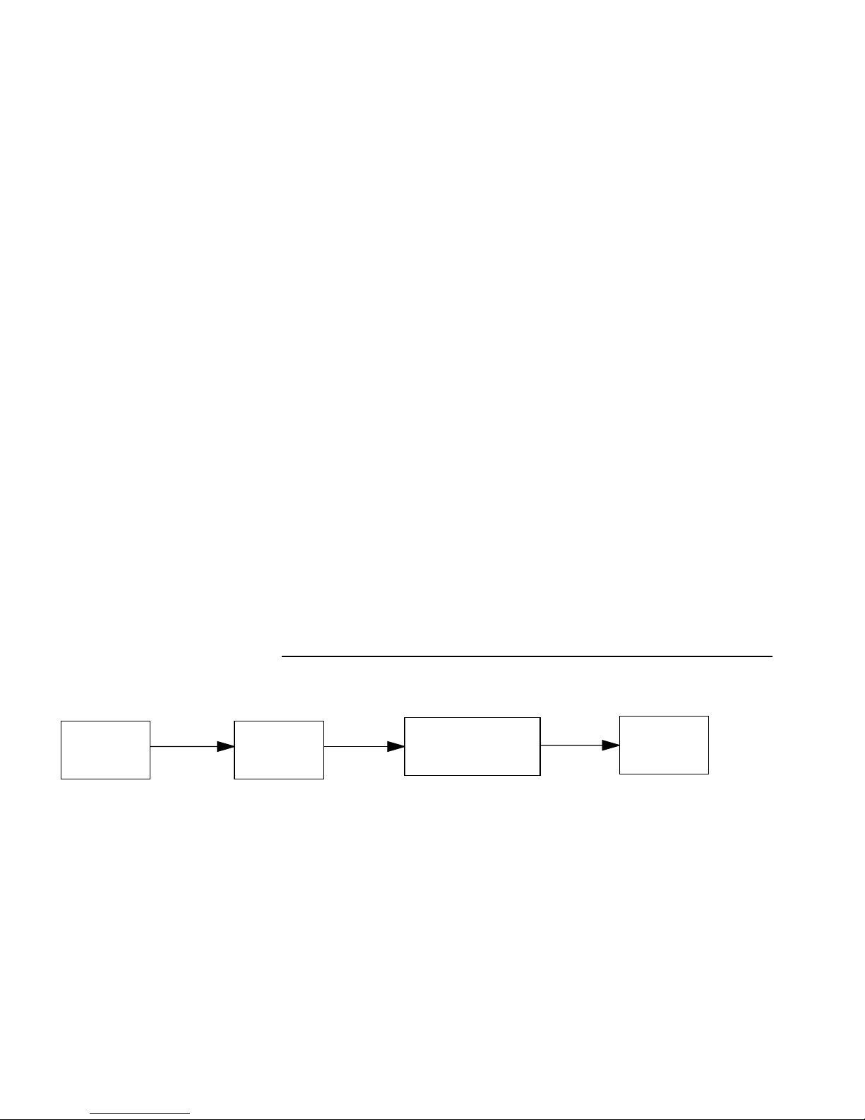
5-4 Netopia ISDN Router Reference Guide
NetBIOS
NetBIOS is a protocol that performs tasks related to the Transport
and Session layers of the OSI model. It can operate over IPX, using
a special broadcast packet known as “IPX Packet type 20” to
communicate with IPX NetBIOS servers.
IPX Spoofing
The Netopia has several IPX features designed to restrict the traffic
on the ISDN link when the unit is not sending or receiving IPX data.
When the link is idle and a user is logged into a Novell server, the
server will send “keep alive” packets to ensure the user is still
there. If the link is idle, the “keep alive” packets will be sent back to
the server by the locally connected Netopia router as though they
came back from the user without bringing up the ISDN link.
Main
Menu
Similarly, “SPX keep alive” packets are treated in this manner. IPX
RIP, and SAP messages will not be sent if the link is down. Together
these features enable the user to remain connected to a Novell
server or SPX peer without bringing up the ISDN link, except to send
and receive actual user data.
IPX setup
Advanced
Config.
The IPX Setup screen is where you configure the Ethernet side of
the Netopia ISDN Router for IPX. The information you enter here
controls how the router routes IPX traffic. Consult your network
administrator to obtain the information you will need, before
changing any of the settings.
Changes made in this screen will only take effect after the Netopia
ISDN Router is reset.
Network
Protocols Setup
IPX
Setup
Page 96

IPX Setup 5-5
To go to the IPX Setup screen, select IPX Setup in the Network
Protocols Setup screen.
IPX Setup
IPX Enabled: Yes
Ethernet Network Address: 00000150
Ethernet Encapsulation... 802.3
Ethernet Path Delay: 1
Ethernet NetBios Packet Forwarding: Yes
Ethernet Incoming SAP Filter Set... <<NONE>>
Detach Filter Set...
Default Gateway Address: 00000000
Filters and Filter Sets...
Return/Enter goes to new screen.
1. To enable IPX routing, select IPX Enabled and toggle it to Yes.
2. Select Ethernet Network Address and enter the network
address of the IPX network connected to the Netopia ISDN
Router’s Ethernet port.
Note: If the Ethernet network address is set to zero, the Router
will attempt to learn the address from any configured IPX device
on the Ethernet network or from the remote IPX network when a
call is established.
3. To change Ethernet encapsulation from the commonly used
802.3 standard, select Ethernet Encapsulation and choose a
different encapsulation method.
Page 97

5-6 Netopia ISDN Router Reference Guide
4. To change the default path delay, select Ethernet Path Delay
and enter a value (in ticks). This value is used to determine the
port cost of using the Ethernet port in IPX RIP calculations.
5. T o enable NetBIOS packet forwarding, select Ethernet NetBIOS
Packet Forwarding and toggle it to Yes. This parameter will
determine whether “IPX Packet type 20” packets are forwarded
on the Ethernet interface. These packets are used by NetBIOS
and some other applications.
6. Select Ethernet Incoming SAP Filter Set to filter incoming IPX
SAP advertisements on the Ethernet. By attaching an incoming
SAP filter on the Ethernet, you can restrict the number of SAP
entries learned on a large IPX network to only those required by
remote users connecting to the Netopia ISDN Router via the
ISDN. An Ethernet SAP filter
have so many servers advertised that the Netopia ISDN Router
would otherwise exhaust its internal memory storing server
entries.
must
be used with networks that
To attach a SAP filter set, first define the filter set using the
Filters and Filter Sets option (see step 8 below). Then select
the filter set from the Ethernet Incoming SAP Filter Set pop-up
menu. To detach the filter set, select Detach Filter Set.
7. Select Default Gateway Address, and enter the network
address of the IPX network to which all packets of unknown
destination address should be routed.
Note: The Default Gateway Address is usually set up to match
the IPX Address in your Network Connection Profile.
8. To configure filters and filter sets, select Filters and Filter Sets
and go to the IPX filters and filter sets screens. For information
on how to configure IPX filters and filter sets, see “IPX filters”
on page 5-11.
Page 98

IPX in connection profiles
IPX can be used with connection profiles to connect to remote IPX
networks. You can configure IPX in a new connection profile when
you first create it in the Add Connection Profile screen.
Profile Name: Easy Setup Profile
Profile Enabled: Yes
IP Enabled: Yes
IP Profile Parameters...
IPX Setup 5-7
Add Connection Profile
IPX Enabled: Yes
IPX Profile Parameters...
Number to Dial:
Optional 2nd Number:
PPP/MP Options...
Telco Options...
Follow these steps to configure IPX in the new connection profile:
1. To enable IPX routing in this connection profile, select IPX
Enabled and toggle it to Yes. When IPX Enabled is set to Yes,
the item IPX Profile Parameters appears below it.
2. To configure IPX routing in this connection profile, select IPX
Profile Parameters and press Return to go to the IPX Profile
Parameters screen.
Page 99

5-8 Netopia ISDN Router Reference Guide
Remote IPX Network: 00000000
Path Delay: 10
NetBios Packet Forwarding: Off
Incoming Packet Filter Set...
Outgoing Packet Filter Set...
Incoming SAP Filter Set...
Outgoing SAP Filter Set...
Detach Filter Sets...
Periodic RIP Timer: 60
Periodic SAP Timer: 60
IPX Profile Parameters
Return accepts * ESC cancels * Left/Right moves insertion point * Del
deletes.
Configure IPX requirements for a remote network connection here.
3. Select Remote IPX Network and enter the network address of
the IPX network being called. Don’t use an address already in
use by another connection profile. If this value is set to zero
and the Netopia ISDN Router is answering a call, the remote
address will be learned when the profile is active. Note that,
unlike IP, the IPX network address is never used in matching a
profile when answering a non-authenticated call. For dial on
demand to work, your Default Gateway should match one of
your IPX addresses in a defined connection profile.
4. T o change the default path delay, select Path Delay and enter a
value (in ticks).
5. To enable NetBIOS packet forwarding, select NetBIOS Packet
Forwarding and toggle it to Yes.
6. To attach a filter set for filtering incoming packets, select
Incoming Packet Filter Set and choose a filter set from the list.
7. To attach a filter set for filtering outgoing packets, select
Outgoing Packet Filter Set and choose a filter set from the list.
Page 100

IPX Setup 5-9
8. To attach a filter set for filtering incoming Service Advertising
Protocol (SAP) packet entries, select Incoming SAP Filter Set
and choose a filter set from the list.
9. To attach a filter set for filtering outgoing SAP packets, select
Outgoing SAP Filter Set and choose a filter set from the list.
10. To detach a filter set from the connection profile, select Detach
Filter Sets and press Return to go to the Detach Filter Sets
screen.
Detach Filter Sets
Incoming Packet Filter Set -- <<NONE>>
Detach Outgoing Packet Filter Set 'fire'
Incoming SAP Filter Set -- <<NONE>>
Detach Outgoing SAP Filter Set 'wall'
Return/Enter to detach Filter Set (if there is one) from this Profile.
Detach IPX Filter Sets from this screen.
11. Select a filter set and press Return to detach. If <<NONE>>
appears in place of a filter set name, no filter set is attached for
that category. Return to the IPX Profile Parameters screen by
pressing the Escape key.
12. To change the periodic RIP timer’s default value, select
Periodic RIP Timer and enter a new value (in seconds).
13. To change the periodic SAP timer’s default value, select
Periodic SAP Timer and enter a new value (in seconds).
You have finished creating the new connection profile.
 Loading...