

Page 1

Netopia™ D-Series DSL DSUs
User’s Reference Guide
D3100-I IDSL
D3232 IDSL
D7100 SDSL
D7171 SDSL
Page 2

Copyright
©2000, Netopia, Inc., v.0300
All rights reserved. Printed in the U.S.A.
This manual and any associated artwork, software, and product designs are copyrighted with
all rights reserved. Under the copyright laws such materials may not be copied, in whole or
part, without the prior written consent of Netopia, Inc. Under the law, copying includes
translation to another language or format.
Netopia, Inc.
2470 Mariner Square Loop
Alameda, CA 94501-1010
U.S.A.
Part Number
For additional copies of this electronic manual, order Netopia part number 6161076-PF-02.
Printed Copies
For printed copies of this manual, order Netopia part number TED-DSU/Doc
(P/N 6161076-00-02).
Page 3

CCCCoooonnnntttteeeennnnttttss
ss
Part I: Getting Started
Chapter 1 — Introduction..........................................................1-9
Overview....................................................................... 1-9
Features and capabilities ............................................. 1-10
In DSU mode ..................................................... 1-10
In Ethernet filtering bridge mode.......................... 1-10
About DSL Bonding...................................................... 1-10
How to use this guide .................................................. 1-11
Chapter 2 — Making the Physical Connections........................2-13
Find a location............................................................. 2-13
What you need ............................................................ 2-13
Identify the connectors and attach the cables................ 2-14
Filtering Bridge mode.......................................... 2-14
DSU mode......................................................... 2-14
Connect Line ports to mutiple DSL lines
(D3232 only) ..................................................... 2-15
Netopia D-Series DSL DSU back panel ports.................. 2-15
Netopia D-Series DSL DSU status lights........................ 2-16
G
B
Chapter 3 — Connecting to Your Local Area Network...............3-19
Netopia D-Series Configuration Modes........................... 3-19
Filtering bridge mode.......................................... 3-19
DSU mode......................................................... 3-20
Readying computers on your local network..................... 3-21
Connecting to an Ethernet network................................ 3-22
10Base-T........................................................... 3-22
Page 4

iv User’s Reference Guide
Chapter 4 — Configuring TCP/IP.............................................4-25
Configuring TCP/IP on Windows 95, 98, or NT computers 4-26
Configuring TCP/IP on Macintosh computers.................. 4-28
Part II: Advanced Configuration
Chapter 5 — Console-Based Management...............................5-33
Connecting a console cable to your Netopia D-Series...... 5-34
Connecting through a Telnet session............................. 5-35
Configuring Telnet software ................................. 5-36
Navigating through the console screens ........................ 5-36
Chapter 6 — WAN and System Configuration...........................6-37
System Configuration screens ...................................... 6-38
Navigating through the system configuration screens...... 6-39
System configuration features............................. 6-39
Management IP setup......................................... 6-40
Filter sets.......................................................... 6-41
Date and time.................................................... 6-41
Console configuration......................................... 6-41
SNMP (Simple Network Management Protocol)..... 6-42
Security............................................................. 6-42
Upgrade feature set ........................................... 6-42
Logging ............................................................. 6-42
Installing the Syslog client .................................. 6-43
DSL Bonding (iMux)...................................................... 6-44
What DSL Bonding does ..................................... 6-44
Netopia DSL Bonding.......................................... 6-45
WAN configuration........................................................ 6-45
Chapter 7 — Monitoring Tools.................................................7-49
Quick View status overview .......................................... 7-49
General status................................................... 7-50
Status lights...................................................... 7-50
Page 5

Contents v
Statistics & Logs......................................................... 7-51
General Statistics .............................................. 7-51
Event histories ............................................................ 7-52
System Information...................................................... 7-55
SNMP......................................................................... 7-55
The SNMP Setup screen..................................... 7-56
SNMP traps....................................................... 7-57
Chapter 8 — Security .............................................................8-59
Suggested security measures....................................... 8-59
User accounts............................................................. 8-59
Telnet access .............................................................. 8-61
About filters and filter sets ........................................... 8-62
What’s a filter and what’s a filter set?.................. 8-62
How filter sets work............................................ 8-62
How individual filters work................................... 8-64
Design guidelines............................................... 8-68
Filtering tutorial ........................................................... 8-69
General filtering terms........................................ 8-69
Basic IP packet components............................... 8-69
Basic protocol types........................................... 8-70
Filter basics....................................................... 8-72
Example IP filters ............................................... 8-73
Working with Filters and filter sets................................. 8-75
Adding a filter set............................................... 8-76
Adding filters to a filter set.................................. 8-78
Viewing filter sets............................................... 8-82
Modifying filter sets............................................ 8-83
Deleting a filter set............................................. 8-83
Generic filters.............................................................. 8-84
About generic filters ........................................... 8-85
G
Page 6

vi User’s Reference Guide
Chapter 9 — Utilities and Diagnostics.....................................9-89
Ping............................................................................ 9-90
Trace Route................................................................. 9-92
Telnet client................................................................. 9-93
Disconnect Telnet console session ............................... 9-94
Factory defaults........................................................... 9-94
Transferring configuration and firmware files with TFTP.... 9-94
Updating firmware .............................................. 9-95
Downloading configuration files ........................... 9-96
Uploading configuration files ............................... 9-97
Transferring configuration and firmware files
with XMODEM.............................................................. 9-97
Updating firmware .............................................. 9-98
Downloading configuration files ........................... 9-99
Uploading configuration files ............................... 9-99
Restarting the system................................................ 9-100
Part III: Appendixes
Appendix A — Troubleshooting..............................................A-103
Configuration problems .............................................. A-103
Console connection problems ........................... A-104
Network problems............................................ A-104
How to reset the Netopia D-Series to factory defaults... A-105
Power outages........................................................... A-105
Technical support ...................................................... A-106
How to reach us............................................... A-106
Appendix B — Binary Conversion Table..................................B-109
Appendix C — Further Reading..............................................C-113
Appendix D — Technical Specifications and Safety Information
............................................................................................D-117
Pinouts for V.35 DCE cable......................................... D-117
Pinouts for D3232 Splitter.......................................... D-119
Page 7

Glossary
Contents vii
Description................................................................ D-120
Power requirements ......................................... D-120
Environment .................................................... D-120
Software and protocols..................................... D-120
Agency approvals....................................................... D-120
Regulatory notices ........................................... D-121
Important safety instructions ............................ D-122
Limited Warranty and Limitation of Remedies
Index
G
Page 8

viii User’s Reference Guide
Page 9

PPPPaaaarrrrtttt IIII:::: GGGGeeeettttttttiiiinnnngggg SSSSttttaaaarrrrtttteeeedd
dd
Page 10

User’s Reference Guide
Page 11

Introduction 1-11
CCCChhhhaaaapppptttteeeerrrr 11
IIIInnnnttttrrrroooodddduuuuccccttttiiiioooonn
OOOOvvvveeeerrrrvvvviiiieeeeww
The Netopia D-Series DSL DSUs are Digital Service Units or intelligent Ethernet filtering bridges for SDSL or
IDSL connections. They feature the ability to sense the connection type (Frame Relay or RFC 1483 DSL) and
automatically configure themselves for use as a DSU to Ethernet bridge. In either configuration the Netopia
D-Series offers management features available locally or remotely, either in-band or out-of-band. The DSU mode
offers a convenient way to migrate existing DDS or T1 service that uses an external CSU/DSU to connect to
SDSL or IDSL. In the intelligent Ethernet bridge mode, the Netopia D-Series includes packet filtering for
enhanced security on the LAN and efficient use of the DSL link.
■
The Netopia D7100 and D7171 use an SDSL link to a Copper Mountain DSLAM for the WAN connection.
The Netopia D3100-I and D3232 use an ISDN Digital Subscriber Line (IDSL) to provide remote users
■
dedicated, digital access, even if they are connected to a central office via a digital loop carrier (DLC)
system or an ISDN repeater.
■
The Netopia D3232 and D7171 use DSL bonding technology, as available through Copper Mountain
DSLAMs, to effectively double or quadruple the bandwidth of the DSL link.
In DSU mode the Auxiliary port functions as a Synchronous serial port supplying a V.35 DCE interface for
connection to another router. In bridging mode the Ethernet hub bridges traffic as a proxy for the MAC address
supplied by the remote end of the DSL link.
11
nn
ww
The MAC address, or Media Access Control address is the physical address of a device connected to a network,
expressed as a 48-bit hexadecimal number. Sometimes this is called the hardware address, and is a unique
number assigned to each device by the manufacturer.
The Netopia D-Series provides an auto-sensing function that determines if the Auxiliary port or the hub is
associated with the DSL connection. In either case you can manage the device via the hub using Telnet or
SNMP, or via the serial console.
The hub effectively has two Ethernet MAC addresses in bridging mode: the proxied address that the remote end
supplied and a local IP address for management purposes.
This section covers the following topics:
“Features and capabilities” on page 1-12
■
“About DSL Bonding” on page 1-12
■
■
“How to use this guide” on page 1-13
Page 12

1-12 User’s Reference Guide
FFFFeeeeaaaattttuuuurrrreeeessss aaaannnndddd ccccaaaappppaaaabbbbiiiilllliiiittttiiiieeeess
ss
The Netopia D-Series DSL DSUs all provide the following features:
■
Status lights (LEDs) for easy monitoring and troubleshooting.
■
Support for console-based management over Telnet or serial cable connection.
Wall-mountable, bookshelf (side-stackable), or desktop-stackable design for efficient space usage.
■
IIIInnnn DDDDSSSSUUUU mmmmooooddddee
DSU mode (Frame Relay): Copper Mountain DSL to V.35 for connection to an external router using
■
ee
RFC1490 Frame Relay protocol.
■
Industry-standard V.35 interface for connection to external router.
■
Management Access: Password protected access to management tools with up to four user names and
passwords.
IIIInnnn EEEEtttthhhheeeerrrrnnnneeeetttt ffffiiiilllltttteeeerrrriiiinnnngggg bbbbrrrriiiiddddggggeeee mmmmooooddddee
Ethernet bridge or LAN extension mode (RFC 1483): Copper Mountain DSL to Ethernet for direct connection
■
ee
to a LAN using RFC 1483 protocol.
■
Inter-operates with Copper Mountain Networks Copper Edge™ access concentrator with integrated
management.
■
Connectivity to Ethernet LANs via built-in 8 port 10Base-T hub with uplink port.
Security Features (Intelligent bridge mode):
■
Packet Filters (8 user definable filter sets using up to 255 rules): IP and MAC layer packet filtering; Filter
packets on source or destination address, service or protocol; filter incoming packets for security, or
outgoing packets for more efficient use of DSL bandwidth.
Management Access: Password protected access to management tools with up to 4 user names and
passwords.
AAAAbbbboooouuuutttt DDDDSSSSLLLL BBBBoooonnnnddddiiiinnnngg
gg
DSL Bonding, also called inverse multiplexing or IMUX, technology combines the bandwidth of multiple DSL
(Digital Subscriber Line) circuits into a single virtual data pipe.
Before DSL Bonding was developed, the maximum speed of a DSL connection was dependent on the
customer's distance from the central office. DSL Bonding allows customers who are located at greater
distances from the central office to aggregate DSL circuits, in order to achieve two or more times the speed
otherwise available to them with a single line.
The premise behind DSL Bonding is to provide a cost-effective means of bridging the bandwidth gap between
relatively low network speeds and much higher rates, thereby allowing high-speed applications to use bandwidth
up to 3 Mbps.
Netopia's DSL routers and DSUs with bonding allow users with 1.5 Mbps SDSL connections to enjoy speeds of
over 3 Mbps, twice as fast as T1. They also allow customers who, because of line quality problems, were
previously limited to a 144 Kbps IDSL connection, to enjoy speeds of up to 576 Kbps using four IDSL lines.
Page 13

Introduction 1-13
HHHHoooowwww ttttoooo uuuusssseeee tttthhhhiiiissss gggguuuuiiiiddddee
This guide is designed to be your single source for information about your Netopia D-Series DSL DSU. It is
intended to be viewed on-line, using the powerful features of the Adobe Acrobat Reader. The information display
has been deliberately designed to present the maximum information in the minimum space on your screen. You
can keep this document open while you perform any of the procedures described, and find useful information
about the procedure you are performing.
If you prefer to work from hard copy rather than on-line documentation, you can also print out all of the manual,
or individual sections. The pages are formatted to print on standard 8 1/2 by 11 inch paper. We recommend
that you print on three-hole punched paper, so you can put the pages in a binder for future reference. For your
convenience, a printed copy can be purchased from Netopia. Order part number TED-DSU/Doc.
This guide is organized into chapters describing the Netopia D-Series’s advanced features. You may want to
read each chapter’s introductory section to familiarize yourself with the various features available.
Use the guide’s table of contents and index to locate informational topics.
ee
Page 14

1-14 User’s Reference Guide
Page 15

Making the Physical Connections 2-15
CCCChhhhaaaapppptttteeeerrrr 22
MMMMaaaakkkkiiiinnnngggg tttthhhheeee PPPPhhhhyyyyssssiiiiccccaaaallll CCCCoooonnnnnnnneeeeccccttttiiiioooonnnnss
22
ss
This section tells you how to make the physical connections to your Netopia D-Series DSL DSU. This section
covers the following topics:
■
“Find a location” on page 2-15
■
“What you need” on page 2-15
“Identify the connectors and attach the cables” on page 2-16
■
■
“Netopia D-Series DSL DSU back panel ports” on page 2-17
■
“Netopia D-Series DSL DSU status lights” on page 2-18
FFFFiiiinnnndddd aaaa llllooooccccaaaattttiiiioooonn
nn
When choosing a location for the Netopia D-Series, consider:
Available space and ease of installation
■
Physical layout of the building and how to best use the physical space available for connecting your Netopia
■
D-Series to the LAN or router
■
Available wiring and jacks
Distance from the point of installation to the next device (length of cable or wall wiring)
■
Ease of access to the front of the unit for configuration and monitoring
■
■
Ease of access to the back of the unit for checking and changing cables
■
Cable length and network size limitations when expanding networks
WWWWhhhhaaaatttt yyyyoooouuuu nnnneeeeeeeedd
dd
Locate all items that you need for the installation.
Included in your Netopia D-Series package are:
The Netopia D-Series DSL DSU
■
■
A power adapter and cord with a mini-DIN8 connector
■
Two RJ-45 10Base-T Ethernet or Line cables
A dual DE-9 and mini-DIN8 to DE-9 console cable (for a PC or a Macintosh)
■
■
An HD-15 to V.35 DCE interface cable
■
Two splitters (D3232 only)
The CustomerCare CD containing an Internet browser, Adobe Acrobat Reader for Windows and Macintosh,
■
ZTerm terminal emulator software and NCSA Telnet for Macintosh, and documentation
Page 16
2-16 User’s Reference Guide
You will need:
■
A Windows 95-, 98-, 2000-, or NT–based PC or a Macintosh computer with Ethernet connectivity for
configuring the Netopia D-Series. This may be built-in Ethernet or an add-on card, with TCP/IP installed and
configured. See Chapter 4, “Configuring TCP/IP.”
An SDSL or IDSL wall outlet wired for a connection to a Competitive Local Exchange Carrier (CLEC) that
■
supports Digital Subscriber Line connections.
IIIIddddeeeennnnttttiiiiffffyyyy tttthhhheeee ccccoooonnnnnnnneeeeccccttttoooorrrrssss aaaannnndddd aaaattttttttaaaacccchhhh tttthhhheeee ccccaaaabbbblllleeeess
ss
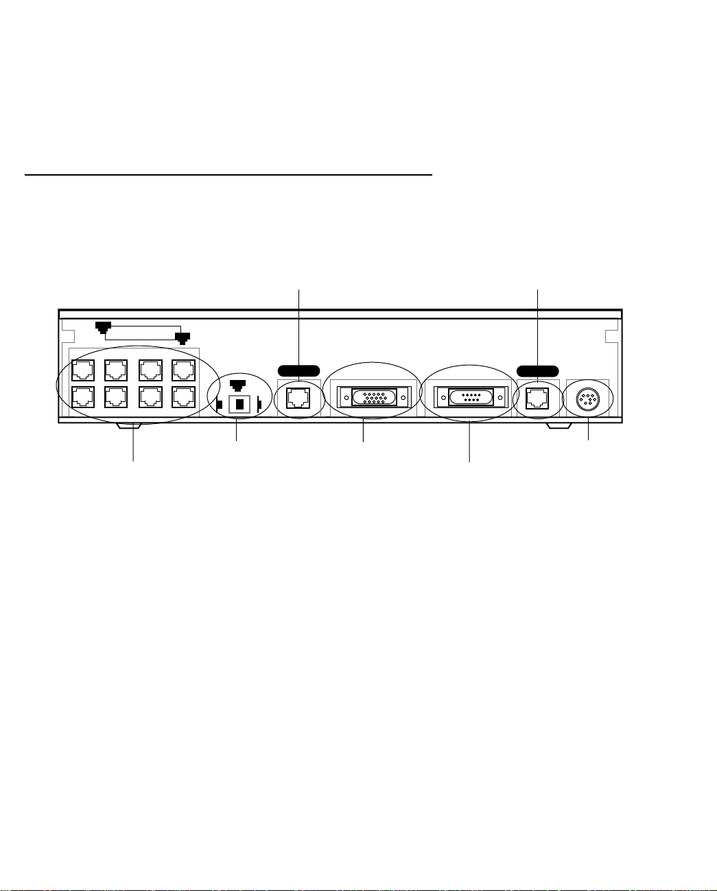
Identify the connectors and switches on the back panel and attach the necessary Netopia D-Series cables.
The figure below displays the back of the Netopia D-Series DSL DSU.
Netopia D-Series DSL DSU back panel
8
Ethernet
1
Crossover switch
8 port Ethernet hub
FFFFiiiilllltttteeeerrrriiiinnnngggg BBBBrrrriiiiddddggggeeee mmmmooooddddee
ee
Normal
1
Uplink
Line port
Line 2
Auxiliary Console Power
Auxiliary port
Console port
Line port
Line 1
Power port
1. Connect the mini-DIN8 connector from the power adapter to the power port, and plug the other end into an
electrical outlet.
2. Connect one end one of the RJ-45 cables to the Line 1 port, and the other end to your SDSL or IDSL wall
outlet.
3. Connect one end of one of the RJ-45 Ethernet cables to any of the Ethernet ports on the Netopia D-Series
and the other end to your computer or to your network.
(If you are connecting the Netopia D-Series to an existing Ethernet hub, use Ethernet port #1 on the
Netopia D-Series and set the crossover switch to the
Uplink
position.)
You should now have: the power adapter plugged in; the Ethernet cable connected between the Netopia
D-Series and your computer or network; and the SDSL or IDSL cable connected between the Netopia
D-Series and the SDSL or IDSL wall outlet.
DDDDSSSSUUUU mmmmooooddddee
ee
1. Connect the mini-DIN8 connector from the power adapter to the power port, and plug the other end into an
electrical outlet.
Page 17

Making the Physical Connections 2-17
2. Connect one end one of the RJ-45 cables to the Line 1 port, and the other end to your SDSL or IDSL wall
outlet.
3. Connect one end of one of the RJ-45 Ethernet cables to any of the Ethernet ports on the Netopia D-Series
and the other end to your computer or to your network.
(If you are connecting the Netopia D-Series to an existing Ethernet hub, use Ethernet port #1 on the
Netopia D-Series and set the crossover switch to the
management access to the Netopia D-Series.
4. Connect the HD-15 end of the supplied V .35 interface cable to the Auxiliary port and the other end to your
external Frame Relay router. The unit will auto-detect filtering bridge mode or DSU mode, based on which
cables are connected and traffic on the lines.
Uplink
position.) This connection will provide
CCCCoooonnnnnnnneeeecccctttt LLLLiiiinnnneeee ppppoooorrrrttttssss ttttoooo mmmmuuuuttttiiiipppplllleeee DDDDSSSSLLLL lllliiiinnnneeeessss ((((DDDD3333222233332222 oooonnnnllllyyyy))
On the Netopia D3232 DSU, you can connect the Line ports to up to 4 DSL lines using the splitters provided
with your equipment.
1. Connect one end of one of the RJ-45 cables to the Line 1 port, and the other end to the port on the single
end of the splitter.
2. Connect one end of another RJ-45 cable to either of the ports on the double end of the splitter, and the
other end of the RJ-45 cable to one of your SDSL or IDSL wall outlets.
3. Connect one end of another RJ-45 cable to the second port on the double end of the splitter, and the other
end of the RJ-45 cable to another of your SDSL or IDSL wall outlets.
4. Repeat steps 1-3 with the Line 2 port, the second splitter, and a third and fourth SDSL or IDSL wall outlets.
NNNNeeeettttooooppppiiiiaaaa DDDD----SSSSeeeerrrriiiieeeessss DDDDSSSSLLLL DDDDSSSSUUUU bbbbaaaacccckkkk ppppaaaannnneeeellll ppppoooorrrrttttss
The following table describes all the Netopia D-Series DSL DSU back panel ports.
Port Description
Power port A mini-DIN8 power adapter cable connection.
Line port 1 and 2 Two RJ-45 telephone-style jacks labelled Line 1 and Line 2 for your SDSL or
IDSL connections.
Console port A DE-9 console port for a direct serial connection to the console screens. You
can use this if you are an experienced user. See “Connecting a console cable to
your Netopia D-Series” on page 5-36.
Auxiliary port An HD-15 auxiliary port for attaching the V.35 interface cable to an external
Frame Relay router in DSU mode. In Filtering Bridge mode you can connect an
external modem to this port for remote out-of-band management. This
application requires separate purchase of the Async cable (Part TE6/DB25).
Crossover switch A crossover switch with Normal and Uplink positions. If you use Ethernet Port
#1 for a direct Ethernet connection between a computer and the Netopia
D-Series, set the switch to the
Netopia D-Series to an Ethernet hub, use Ethernet port #1 on the Netopia
D-Series and set the switch to the
Normal
Uplink
))
ss
position. If you are connecting the
position.
Page 18
2-18 User’s Reference Guide
Port Description
8-port Ethernet hub Eight 10Base-T Ethernet jacks. You will use one of these to configure the
Netopia D-Series. For a new installation, use the Ethernet connection.
Alternatively, you can use the console connection to run console-based
management using a direct serial connection. You can either connect your
computer directly to any of the Ethernet ports on the Netopia D-Series, or
connect both your computer and the Netopia D-Series to an existing Ethernet
hub on your LAN.
NNNNeeeettttooooppppiiiiaaaa DDDD----SSSSeeeerrrriiiieeeessss DDDDSSSSLLLL DDDDSSSSUUUU ssssttttaaaattttuuuussss lllliiiigggghhhhttttss
ss
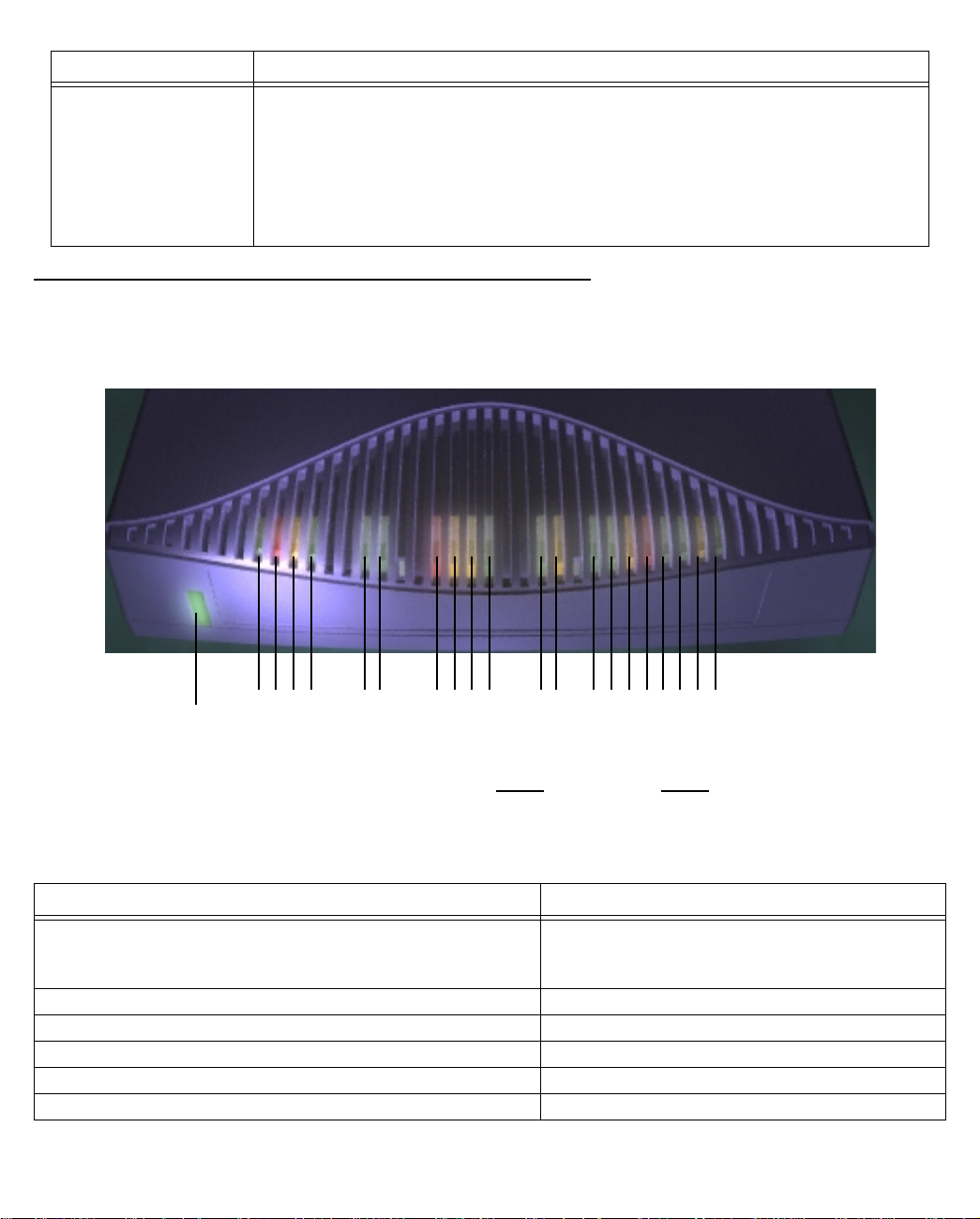
The figure below represents the Netopia D-Series status light (LED) panel.
Netopia D-Series LED front panel
2 3 4 5 6 7 8 9 1011 12 13 1415 16171819 20 21
1
y
Power
Ready
Channel 1
Management
WAN 1 WAN 2 Ethernet
Console
Channel 2
Auxiliar
Management
Ready
Channel 1
Channel 2
Traffic
Collision
Link/Receive
The following table summarizes the meaning of the various LED states and colors:
When this happens... the LEDs...
The corresponding line passes supervisory traffic between
2 or 8 flashes
yellow
the Digital Subscriber Line Access Multiplexer (DSLAM) and
the Netopia D-Series
The WAN interface is operational 3 or 9 is
The line is unavailable 3 or 9 flashes
The WAN on Channel 1 has carrier 4 or 10 is
Data is transmitted or received on the WAN on Channel 1 4 or 10 flashes
The WAN on Channel 2 has carrier 5 or 11 is
green
green
green
.
red
.
.
yellow
. (D3232 only)
.
.
Page 19

Making the Physical Connections 2-19
When this happens... the LEDs...
Data is transmitted or received on the WAN on Channel 2 5 or 11 flashes yellow. (D3232 only)
Console cable is attached and has carrier 6 and 7 are green.
Data is transmitted or received 6 and 7 flash yellow.
Data is transmitted or received by the ethernet controller 12 flashes yellow.
The Ethernet interface detects a collision 13 flashes red.
Link is detected 14 though 21 are solid green.
Data are received on their respective ports 14 though 21 flash green.
Note: Console carrier (6) is ignored if the console is not configured for a remote modem.
Page 20

2-20 User’s Reference Guide
Page 21
Connecting to Your Local Area Network 3-21
CCCChhhhaaaapppptttteeeerrrr 33
CCCCoooonnnnnnnneeeeccccttttiiiinnnngggg ttttoooo YYYYoooouuuurrrr LLLLooooccccaaaallll AAAArrrreeeeaaaa NNNNeeeettttwwwwoooorrrrkk
33
kk
This chapter describes how to physically connect the Netopia D-Series to your local area network (LAN). Before
you proceed, make sure the Netopia D-Series is properly configured. You can customize the Netopia D-Series’s
configuration for your particular LAN requirements using console-based management (see “Console-Based
Management” on page 5-35).
This section covers the following topics:
■ “Netopia D-Series Configuration Modes” on page 3-21
■ “Readying computers on your local network” on page 3-23
■ “Connecting to an Ethernet network” on page 3-24
NNNNeeeettttooooppppiiiiaaaa DDDD----SSSSeeeerrrriiiieeeessss CCCCoooonnnnffffiiiigggguuuurrrraaaattttiiiioooonnnn MMMMooooddddeeeess
ss
The Netopia D-Series DSL DSU can be used in either of two ways:
■ as an intelligent Ethernet filtering bridge for DSL connections, or
■ as a Digital Service Unit
When the appropriate cables are connected, it senses the connection type (Frame Relay or ATM FUNI) and
automatically configures itself for use as a DSU or a DSL to Ethernet bridge.
See the following sections for suggestions on how to connect the Netopia D-Series to different types of
networks.
FFFFiiiilllltttteeeerrrriiiinnnngggg bbbbrrrriiiiddddggggeeee mmmmooooddddee
ee
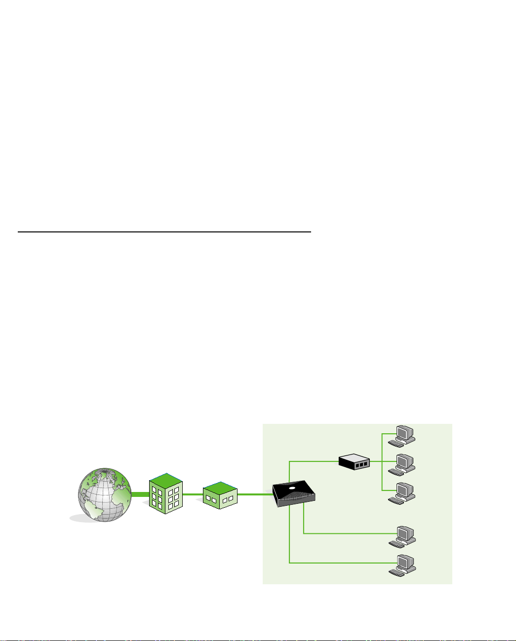
The following figure shows a typical configuration for the filtering bridge mode:
BUSINESS
Servers or
T
E
R
N
I
N
E
H
T
E
T
ISP
CENTRAL
OFFICE
SDSL
HUB
7
Netopia D
SDSL CSU/DSU
100
Workstations
Servers or
Workstations
Page 22
3-22 User’s Reference Guide
In bridge mode the Netopia D-Series performs a simple algorithm. When the Netopia D-Series receives a packet
on the Ethernet hub, the packet is examined for its destination Media Access Control (MAC) address.
The MAC address is the physical address of a device connected to a network, expressed as a 48-bit
hexadecimal number. Sometimes this is called the hardware address, and is a unique number assigned to each
device by the manufacturer.
If the destination MAC address is the Netopia D-Series’s MAC address, based on its serial number, and it is for
management purposes (Telnet or SNMP) or is an ICMP that needs response, it is accepted. If it is the MAC
address that is being proxied (supplied by the DSLAM) it is encapsulated in ATM FUNI and transmitted over the
DSL connection. A packet received from the DSL connection will be de-encapsulated and its MAC address
examined. Either it is management traffic for the Netopia D-Series, or it is encapsulated for Ethernet and
transmitted over the hub.
DDDDSSSSUUUU mmmmooooddddee
ee
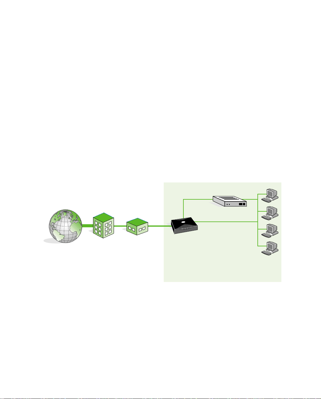
The DSU behavior is similar, except that the datalink encapsulation on the WAN is Frame Relay, and the
destination for packets from the WAN is the Auxiliary port. The Ethernet hub is only available for management
(Telnet or SNMP).
A special male HD-15 to female V.35 cable supports the Netopia D-Series as a DCE connecting the Auxiliary
port to a Frame Relay Access Device (FRAD) such as a sync serial router.
The following figure shows a typical configuration for the DSU mode:
BUSINESS
7
100
V.
T
E
R
N
I
N
E
H
T
E
T
ISP
CENTRAL
OFFICE
SDSL
Netopia D
SDSL CSU/DSU
Router
35
Ethernet (management)
Servers or
Workstations
The sections that follow refer to the filtering bridge mode only.
Page 23
Connecting to Your Local Area Network 3-23
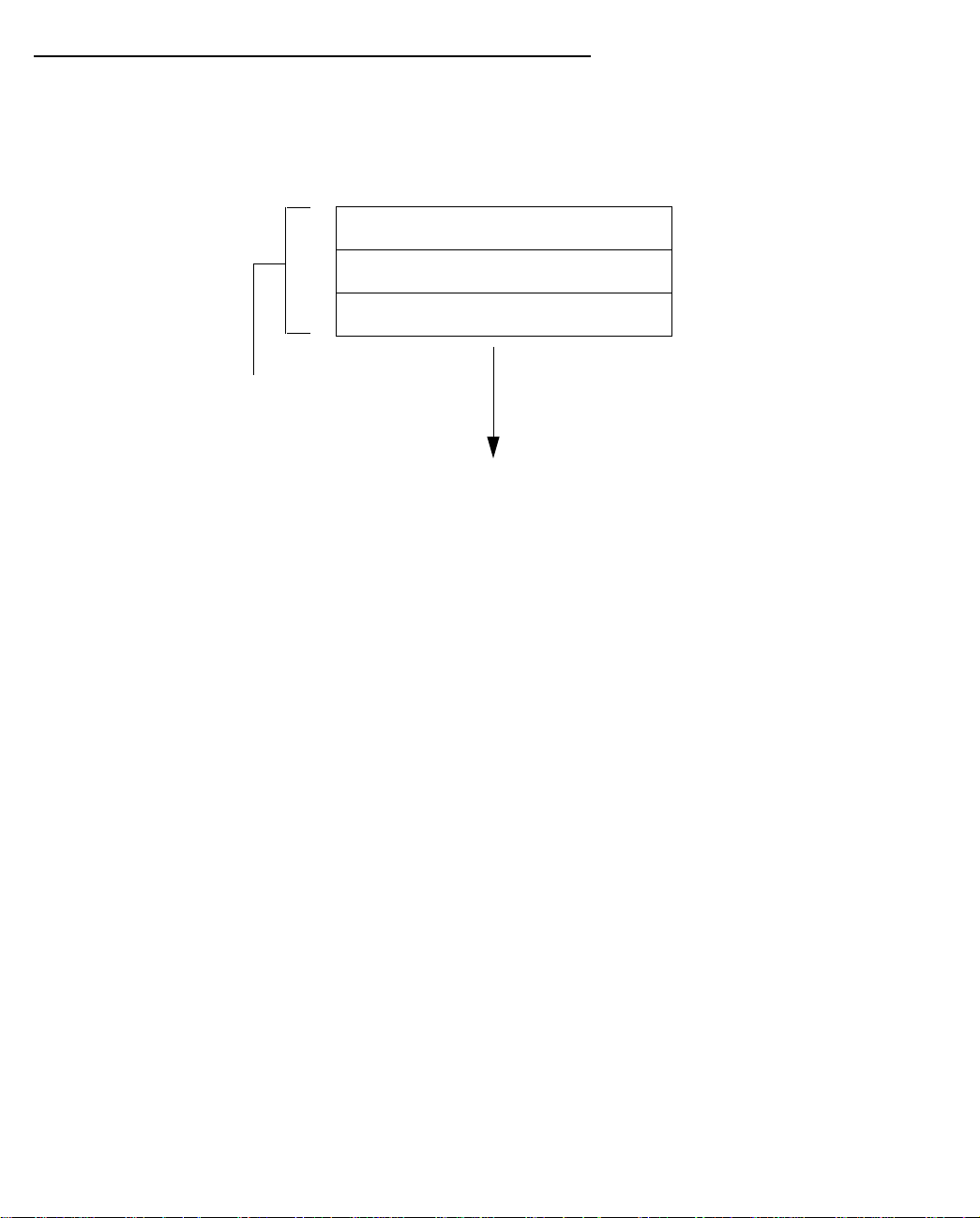
RRRReeeeaaaaddddyyyyiiiinnnngggg ccccoooommmmppppuuuutttteeeerrrrssss oooonnnn yyyyoooouuuurrrr llllooooccccaaaallll nnnneeeettttwwwwoooorrrrkk
PC and Macintosh computers must have certain components installed before they can communicate through
the Netopia D-Series. The following illustration shows the minimal requirements for a typical PC or Macintosh
computer.
Application software
TCP/IP stack
Ethernet Driver
Your PC
or Macintosh
computer
To the Netopia D-Series
Application software: This is the software you use to send e-mail, browse the World Wide Web, read
newsgroups, etc. These applications may require some configuration. Examples include the Eudora e-mail client
and the Web browsers Microsoft Internet Explorer and Netscape Navigator.
TCP/IP stack: This is the software that lets your PC or Macintosh communicate using Internet protocols.
TCP/IP stacks must be configured with some of the same information you used to configure the Netopia
D-Series. There are a number of TCP/IP stacks available for PC computers. Windows 95 includes a built-in
TCP/IP stack. See “Configuring TCP/IP on Windows 95 or 98 computers” on page 4-28. Macintosh computers
use either MacTCP or Open Transport. See “Configuring TCP/IP on Macintosh computers” on page 4-30.
kk
Ethernet: Ethernet hardware and software drivers enable your PC or Macintosh computer to communicate on
the LAN.
EtherTalk and LocalTalk: These are AppleTalk protocols used over Ethernet.
Once the Netopia D-Series is properly configured and connected to your LAN, PC and Macintosh computers that
have their required components in place will be able to connect to the Internet or other remote IP networks.
Page 24
3-24 User’s Reference Guide
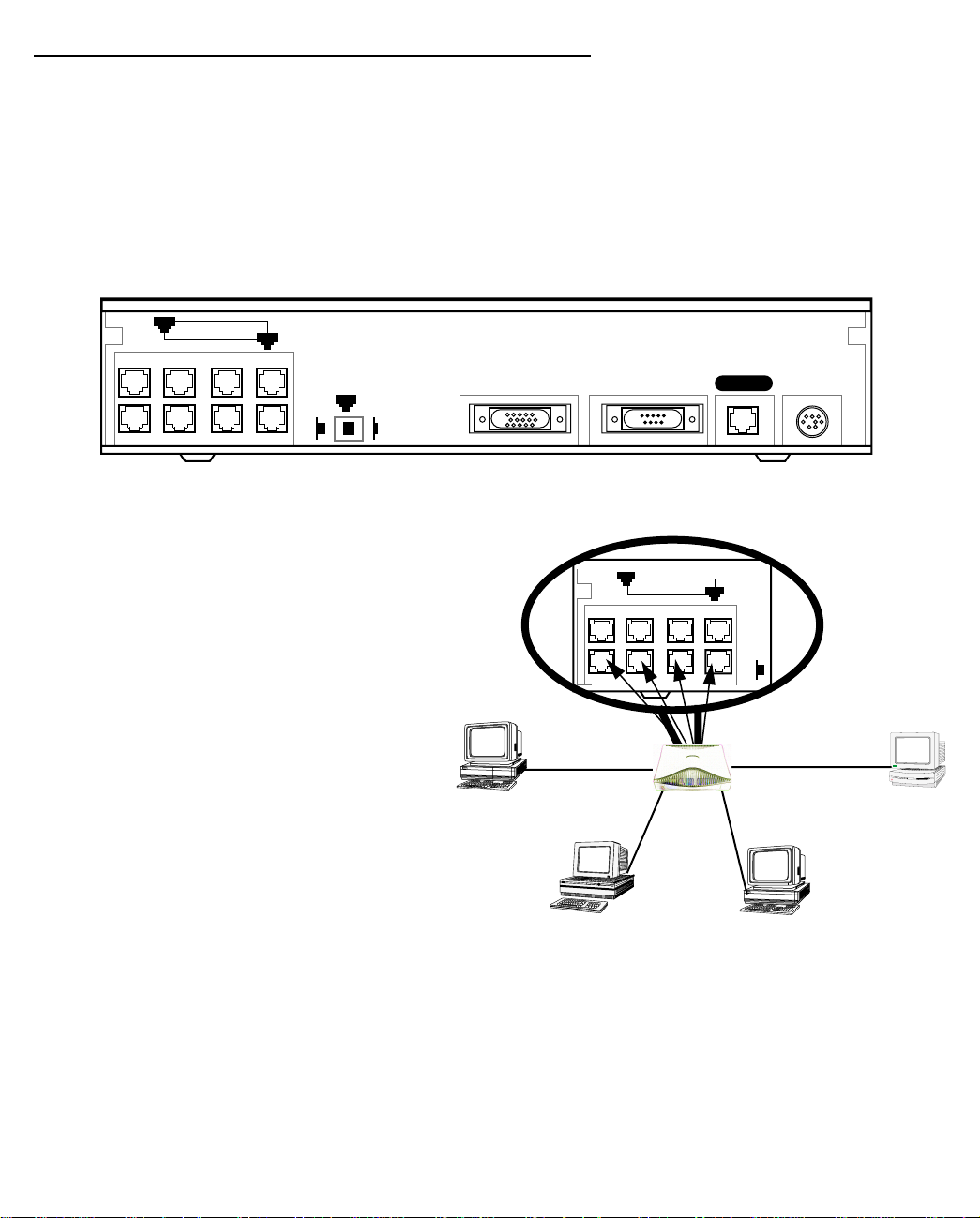
CCCCoooonnnnnnnneeeeccccttttiiiinnnngggg ttttoooo aaaannnn EEEEtttthhhheeeerrrrnnnneeeetttt nnnneeeettttwwwwoooorrrrkk
kk
The Netopia D-Series supports Ethernet connections through its eight Ethernet ports. The Netopia D-Series
automatically detects which Ethernet port is in use.
11110000BBBBaaaasssseeee----TT
TT
You can connect a standard 10Base-T Ethernet network to the Netopia D-Series using any of its available
Ethernet ports.
Netopia D-Series back panel
8
Ethernet
The Netopia D-Series in a 10Base-T network
1
Normal
1
Auxiliary Console Power
Uplink
Line
T o connect your 10Base-T network to the Netopia
D-Series through an Ethernet port, use a
10Base-T cable with RJ-45 connectors.
8
Ethernet
1
If you have more than eight devices to connect,
you can attach additional devices using another
Nor-
10Base-T hub.
Page 25
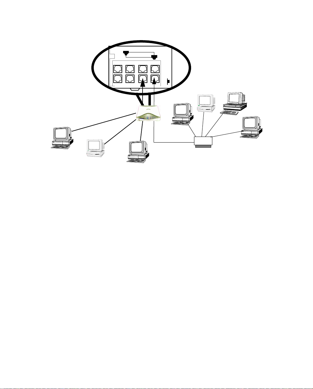
Connecting to Your Local Area Network 3-25
If you add devices connected through a hub, connect the hub to Ethernet port number 1 on the Netopia
D-Series and set the Normal/Uplink switch to Uplink.
8
Ethernet
PC
Macintosh
PC
1
Nor-
10Base-T
Hub
Page 26

3-26 User’s Reference Guide
Page 27

Configuring TCP/IP 4-27
CCCChhhhaaaapppptttteeeerrrr 44
CCCCoooonnnnffffiiiigggguuuurrrriiiinnnngggg TTTTCCCCPPPP////IIIIPP
Computers on your network must have TCP/IP installed and configured. This chapter tells you how to configure
TCP/IP on the desktop computers on your network.
This chapter covers the following topics:
■ “Configuring TCP/IP on Windows 95 or 98 computers” on page 28
■ “Configuring TCP/IP on Macintosh computers” on page 30
Note: For information on configuring TCP/IP on Windows 2000 or NT computers, please see the Microsoft
documentation.
44
PP
Page 28
4-28 User’s Reference Guide
CCCCoooonnnnffffiiiigggguuuurrrriiiinnnngggg TTTTCCCCPPPP////IIIIPPPP oooonnnn WWWWiiiinnnnddddoooowwwwssss 99995555 oooorrrr 99998888 ccccoooommmmppppuuuutttteeeerrrrss
Configuring TCP/IP on a Windows computer requires the following:
■ An Ethernet card (also known as a network adapter)
■ The TCP/IP protocol must be “bound” to the adapter or card
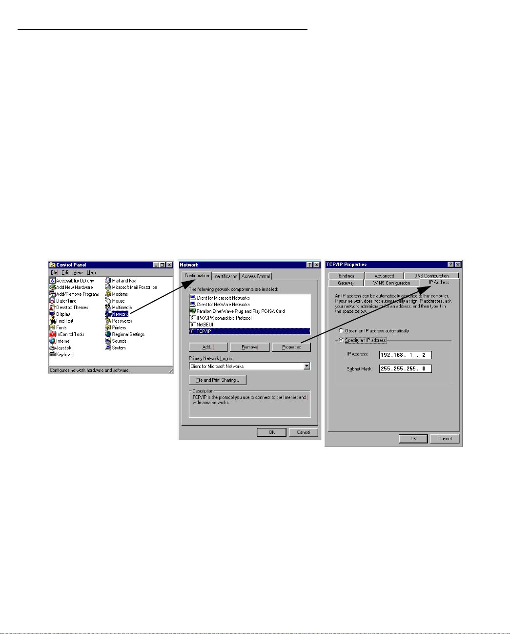
If you are manually configuring for a fixed or static IP address, perform the following:
1. Go to Start Menu/Settings/Control Panels and double click the Network icon. From the Network
components list, select the Configuration tab.
2. Select TCP/IP-->Your Network Card. Then select Properties. In the TCP/IP Properties screen (shown
below), select the IP Address tab. Click “Specify an IP Address.”
Enter the following:
IP Address: 192.168.1.2
Subnet Mask: 255.255.255.0, or for 12-user models 255.255.255.240
This address is an example of one that can be used to configure the Netopia D-Series with the Easy
option in the SmartStart Wizard. Your ISP or network administrator may ask you to use a different IP
address and subnet mask.
ss
Page 29
Configuring TCP/IP 4-29
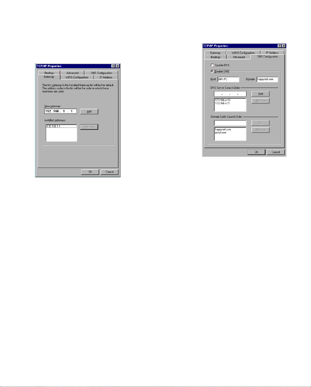
3. Click on the Gateway tab (shown below).
Under “New gateway,” enter
192.168.1.1. Click Add. This is the
Netopia D-Series’s pre-assigned IP
address.
4. Click OK in this window, and the next window. When prompted, reboot the computer.
Click on the DNS Configuration tab. Click Enable DNS.
Enter the following
information:
Host: Type the name
you want to give to
this computer.
Domain: Type your
domain name. If you
don't have a domain
name, type your ISP's
domain name; for
example,
netopia.com.
DNS Server Search
Order: Type the
primary DNS IP
address given to you
by your ISP. Click
Add. Repeat this process for the secondary DNS.
Domain Suffix Search Order: Enter the same domain
name you entered above.
Note: You can also use these instructions to configure other computers on your network with manual or static
IP addresses. Be sure each computer on your network has its own IP address.
Page 30
4-30 User’s Reference Guide
CCCCoooonnnnffffiiiigggguuuurrrriiiinnnngggg TTTTCCCCPPPP////IIIIPPPP oooonnnn MMMMaaaacccciiiinnnnttttoooosssshhhh ccccoooommmmppppuuuutttteeeerrrrss
ss
The following is a quick guide to configuring TCP/IP for MacOS computers. Configuring TCP/IP in a Macintosh
computer requires the following:
■ You must have either Open Transport or Classic Networking (MacTCP) installed.
■ You must have built-in Ethernet or a third-party Ethernet card and its associated drivers installed in your
Macintosh.
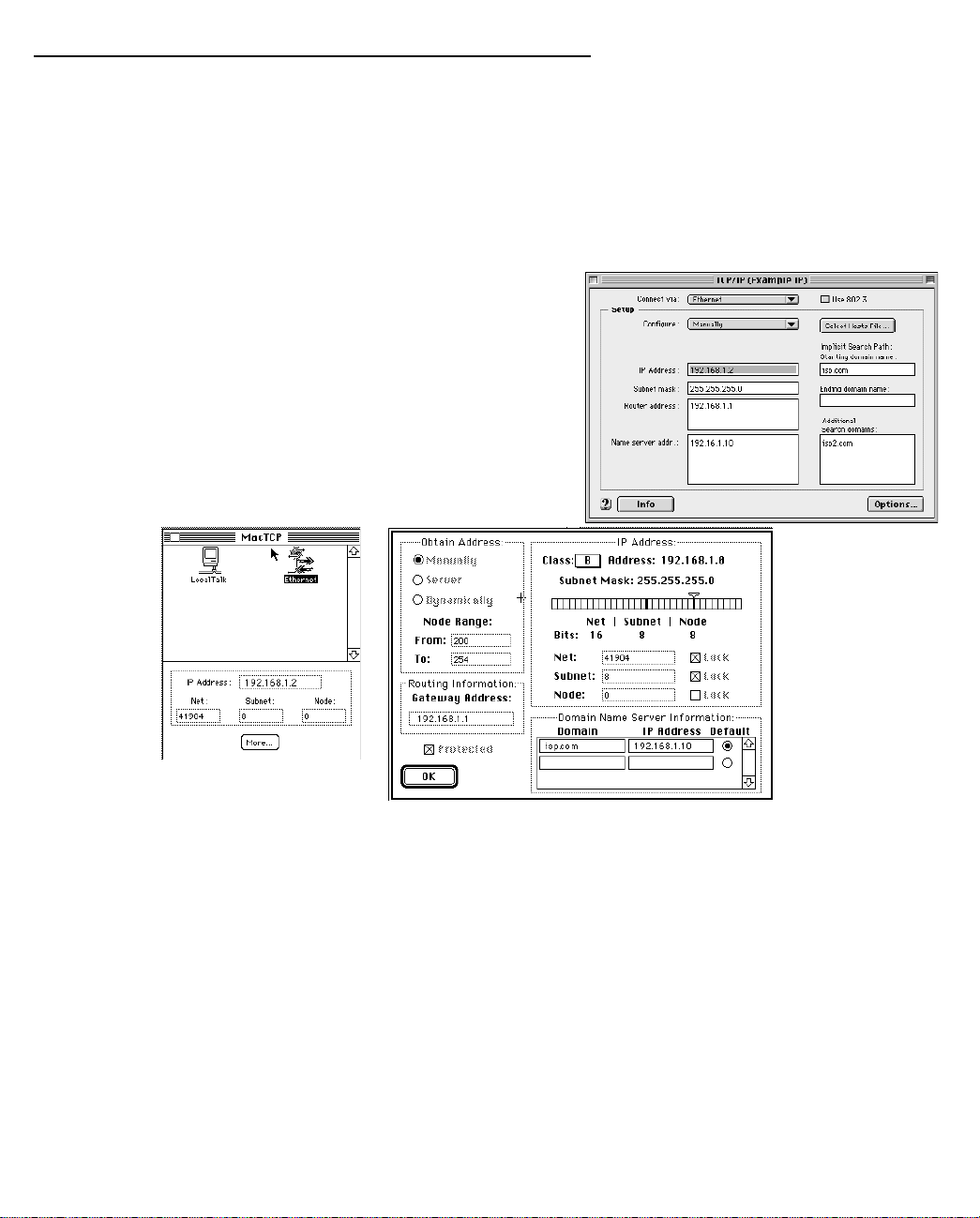
If you are manually configuring for a fixed or static IP address,
perform the following:
1. Go to the Apple menu. Select Control Panels and then
TCP/IP or MacTCP.
2. With the TCP/IP window open, go to the Edit menu and
select User Mode. Choose Advanced and click OK.
Or, in the MacTCP window, select Ethernet and click the
More button.
3. In the TCP/IP window or in the MacTCP/More window, select or type information into the fields as shown in
the following table.
Option: Select/Type:
Connect via: Ethernet
Configure: Manually
IP Address: 192.168.1.2
Subnet mask: 255.255.255.0, or for 12-user models
255.255.255.240
Router or Gateway address: 192.168.1.1
Name server address: Enter the primary and secondary name server
addresses given to you by your ISP
Page 31

Configuring TCP/IP 4-31
Option: Select/Type:
Implicit Search Path:
Starting domain name:
Enter your domain name; if you do not have a
domain name, enter the domain name of your ISP
4. Close the TCP/IP or MacTCP control panel and save the settings.
5. If you are using MacTCP, you must restart the computer. If you are using Open Transport, you do not need
to restart. These are the only fields you need to modify in this screen.
Note: You can also use these instructions to configure other computers on your network with manual or static
IP addresses. Be sure each computer on your network has its own IP address.
Page 32

4-32 User’s Reference Guide
Page 33

PPPPaaaarrrrtttt IIIIIIII:::: AAAAddddvvvvaaaannnncccceeeedddd CCCCoooonnnnffffiiiigggguuuurrrraaaattttiiiioooonn
nn
Page 34

User’s Reference Guide
Page 35

Console-Based Management 5-35
CCCChhhhaaaapppptttteeeerrrr 55
CCCCoooonnnnssssoooolllleeee----BBBBaaaasssseeeedddd MMMMaaaannnnaaaaggggeeeemmmmeeeennnntt
55
tt
Console-based management is a menu-driven interface for the capabilities built in to the Netopia D-Series.
Console-based management provides access to a wide variety of features that the Netopia D-Series supports.
You can customize these features for your individual setup. This chapter describes how to access the
console-based management screens.
This section covers the following topics:
■ “Connecting a console cable to your Netopia D-Series” on page 5-36
■ “Connecting through a Telnet session” on page 5-37
■ “Navigating through the console screens” on page 5-38
Console-based management screens contain five entry points to the Netopia D-Series configuration and
monitoring features. The entry points are displayed in the Main Menu shown below:
Netopia D3232 v4.6
WAN Configuration...
System Configuration...
Utilities & Diagnostics...
Statistics & Logs...
Quick View...
Return/Enter for WAN Line configuration.
You always start from this main screen.
Note: Although it references the Netopia D3232, this screen applies to all Netopia D-Series DSL DSUs.
■ The WAN Configuration menu displays and permit changing the following options:
■ Clock Source: Network or Internal
■ Bridge Mode Filter Set: Basic Firewall or NetBIOS Filter
■ Remove Filter Set
■ The System Configuration menus display and permit changing:
■ Management IP Setup. See “Management IP setup” on page 6-42.
Page 36

5-36 User’s Reference Guide
■ Filter Sets (Firewalls). See “Security” on page 8-61.
■ Date and time. See “Date and time” on page 6-43.
■ Console configuration. See “Connecting a console cable to your Netopia D-Series” on page 5-36.
■ SNMP (Simple Network Management Protocol). See “SNMP” on page 7-57.
■ Security. See “Security” on page 8-61.
■ Upgrade feature set. See “Upgrade feature set” on page 6-44.
■ Logging. See “Event histories” on page 7-54.
■ The Utilities & Diagnostics menus provide a selection of seven tools for monitoring and diagnosing the
Netopia D-Series's behavior, as well as for updating the firmware and rebooting the system. See “Utilities
and Diagnostics” on page 9-91 for detailed information.
■ The Statistics & Logs menus display nine sets of tables and device logs that show information about your
Netopia D-Series, your network and their history. See “Statistics & Logs” on page 7-53 for detailed
information.
■ The Quick View menu displays at a glance current real-time operating information about your Netopia
D-Series. See “Quick View status overview” on page 7-51 for detailed information.
CCCCoooonnnnnnnneeeeccccttttiiiinnnngggg aaaa ccccoooonnnnssssoooolllleeee ccccaaaabbbblllleeee ttttoooo yyyyoooouuuurrrr NNNNeeeettttooooppppiiiiaaaa DDDD----SSSSeeeerrrriiiieeeess
ss
If you will be assigning an IP address to the Netopia D-Series other than the default 192.168.1.1, it is best to
access the unit through the serial console.
You can perform all of the system configuration activities for your Netopia D-Series through a local serial
console connection using terminal emulation software, such as HyperTerminal provided with Windows95 on the
PC, or ZTerm, included on the CustomerCare CD, for Macintosh computers.
The Netopia D-Series back panel has a connector labeled “Console” for attaching the Netopia D-Series to either
a PC or Macintosh computer via the serial port on the computer. (On a Macintosh computer, the serial port is
called the Modem port or Printer port.) This connection lets you use the computer to configure and monitor the
Netopia D-Series via the console screens.
8
Ethernet
1
Normal
1
Auxiliary Console Power
Uplink
Line
Console connection port
DB-9 (male)
Page 37

Console-Based Management 5-37
To connect the Netopia D-Series to your computer for serial console communication, use the supplied dual
console cable connector end appropriate to your platform:
■ One DB-9 connector end attaches to a PC.
■ The mini-DIN8 connector end attaches to a Macintosh computer.
■ The DB-9 end of the Console cable attaches to the Netopia D-Series’s Console port.
■ If you connect a PC with Microsoft Windows 95 or NT, you can use the HyperTerminal application bundled
with the operating system.
■ If you connect a Macintosh computer, you can use the ZTerm terminal emulation program on the supplied
CustomerCare CD.
Launch your terminal emulation software and configure the communications software for the values shown in
the table below. These are the default communication parameters that the Netopia D-Series uses.
Parameter Suggested Value
Terminal type PC: ANSI-BBS
Mac: ANSI, VT-100, or VT-200
Data bits 8
Parity None
Stop bits 1
Speed 57600 bits per second
Flow Control None
Note: The Netopia D-Series firmware contains an autobaud detection feature. If you
are at any screen on the serial console, you can change your baud rate and press
Return (HyperTerminal for the PC requires a disconnect). The new baud rate is
displayed at the bottom of the screen.
CCCCoooonnnnnnnneeeeccccttttiiiinnnngggg tttthhhhrrrroooouuuugggghhhh aaaa TTTTeeeellllnnnneeeetttt sssseeeessssssssiiiioooonn
nn
Features of the Netopia D-Series can be configured through the console screens via Telnet.
Before you can access the console screens through Telnet, you must have:
■ A network connection locally to the Netopia D-Series or IP access to the Netopia D-Series.
The default IP address of the Netopia D-Series is 192.168.1.1, subnet mask 255.255.255.0. In order to
perform the initial configuration via Telnet your computer must have an IP address between 192.168.1.2
and 192.168.1.254, subnet mask 255.255.255.0.
Caution: If you change the Netopia D-Series’s IP address to some value outside of this range, you may lose
contact with the unit via Telnet.
Page 38

5-38 User’s Reference Guide
Alternatively, you can have a direct serial console cable connection using the provided console cable for
your platform (PC or Macintosh) and the Console port on the back of the Netopia D-Series. For more
information on attaching the console cable, see “Connecting a console cable to your Netopia D-Series” on
page 5-36.
■ Telnet software installed on the computer you will use to configure the Netopia D-Series
CCCCoooonnnnffffiiiigggguuuurrrriiiinnnngggg TTTTeeeellllnnnneeeetttt ssssooooffffttttwwwwaaaarrrree
If you are configuring your Netopia D-Series using a Telnet session, your computer must be running a Telnet
software program.
■ If you connect a PC with Microsoft Windows, you can use a Windows Telnet application or simply run Telnet
from the Start menu.
■ If you connect a Macintosh computer, you can use the NCSA Telnet program supplied on the CustomerCare
CD. You install NCSA Telnet by simply dragging the application from the CD to your hard disk.
NNNNaaaavvvviiiiggggaaaattttiiiinnnngggg tttthhhhrrrroooouuuugggghhhh tttthhhheeee ccccoooonnnnssssoooolllleeee ssssccccrrrreeeeeeeennnnss
Use your keyboard to navigate the Netopia D-Series’s configuration screens, enter and edit information, and
make choices. The following table lists the keys to use to navigate through the console screens.
Move through selectable items in a screen or pop-up menu Up, Down, Left, and
To set a change to a selected item or open a pop-up menu of
options for a selected item like entering an upgrade key
Change a toggle value (Yes/No, On/Off) Tab
Restore an entry or toggle value to its previous value Esc
ee
ss
To... Use These Keys...
Right Arrow
Return or Enter
Move one item up Up arrow or Control + k
Move one item down Down arrow or Control + O
Display a dump of the device event log Control + e
Display a dump of the WAN event log Control + f
Refresh the screen Control + L
Go to topmost selectable item <
Go to bottom right selectable item >
Page 39

WAN and System Configuration 6-39
CCCChhhhaaaapppptttteeeerrrr 66
WWWWAAAANNNN aaaannnndddd SSSSyyyysssstttteeeemmmm CCCCoooonnnnffffiiiigggguuuurrrraaaattttiiiioooonn
This chapter describes how to use the console-based management screens to access and configure advanced
features of your Netopia D-Series DSL DSU. You can customize these features for your individual setup. These
menus provide a powerful method for experienced users to set up their Netopia D-Series’s connection and
system configuration.
This chapter also describes DSL Bonding, or iMux, and how to configure your Netopia D-Series equipment to
use it.
This section covers the following topics:
■ “System Configuration screens” on page 6-40
■ “Navigating through the system configuration screens” on page 6-41
■ “System configuration features” on page 6-41
■ “DSL Bonding (iMux)” on page 6-46
■ “WAN configuration” on page 6-47
66
nn
Page 40

6-40 User’s Reference Guide
SSSSyyyysssstttteeeemmmm CCCCoooonnnnffffiiiigggguuuurrrraaaattttiiiioooonnnn ssssccccrrrreeeeeeeennnnssss
You can connect to the Netopia D-Series’s system configuration screens in either of two ways:
■ By using Telnet with the Netopia D-Series’s Ethernet port IP address. The default is 192.168.1.1, subnet
mask 255.255.255.0.
■ Through the console port, using a local terminal (see “Connecting a console cable to your Netopia
D-Series” on page 5-36)
You can also retrieve the Netopia D-Series’s configuration information and remotely set its parameters using
the Simple Network Management Protocol (see “SNMP” on page 7-57).
Open a Telnet connection to the Netopia D-Series’s IP address; for example, the default “192.168.1.1.”
The console screen will open to the Main Menu, similar to the screen shown below:
Netopia D3232 v4.6
WAN Configuration...
System Configuration...
Utilities & Diagnostics...
Statistics & Logs...
Quick View...
Return/Enter displays options for the system.
You always start from this main screen.
Note: Although it references the Netopia D3232, this screen applies to all Netopia D-Series DSL DSUs.
Page 41

WAN and System Configuration 6-41
NNNNaaaavvvviiiiggggaaaattttiiiinnnngggg tttthhhhrrrroooouuuugggghhhh tttthhhheeee ssssyyyysssstttteeeemmmm ccccoooonnnnffffiiiigggguuuurrrraaaattttiiiioooonnnn ssssccccrrrreeeeeeeennnnss
To help you find your way to particular screens, some sections in this guide begin with a graphical path guide
similar to the following example:
Main
Menu
This particular path guide shows how to get to the Management IP Setup screens. The path guide represents
these steps:
1. Beginning in the Main Menu, select System Configuration and press Return. The System Configuration
screen appears.
2. Select Management IP Setup and press Return. The IP Setup screen appears.
To go back in this sequence of screens, use the Escape key.
SSSSyyyysssstttteeeemmmm ccccoooonnnnffffiiiigggguuuurrrraaaattttiiiioooonnnn ffffeeeeaaaattttuuuurrrreeeess
The Netopia D-Series DSL DSU’s default settings may be all you need to configure your Netopia D-Series. Some
users, however, require advanced settings or prefer manual control over the default selections. For these users,
the Netopia D-Series provides system configuration options.
To access the system configuration screens, select System Configuration in the Main Menu, then press
Return.
System
Configuration
ss
Management IP
Setup
ss
IP Setup
The System Configuration menu screen appears:
System Configuration
Management IP Setup...
Filter Sets...
Date and Time...
Console Configuration...
SNMP (Simple Network Management Protocol)...
Security...
Upgrade Feature Set...
Logging...
Return/Enter to configure Networking Protocols (such as TCP/IP).
Use this screen if you want options beyond Easy Setup.
Options available under the System Configuration menu are described in the following sections.
Page 42

6-42 User’s Reference Guide
MMMMaaaannnnaaaaggggeeeemmmmeeeennnntttt IIIIPPPP sssseeeettttuuuupp
pp
Consult your network administrator or Internet service provider to obtain the IP setup information such as the
Ethernet IP address, Ethernet subnet mask, default IP gateway. You will need this information before changing
any of the settings in this screen. Changes made in this screen will take effect only after the Netopia D-Series
is reset.
To go to the IP Setup options screen, from the Main Menu, select System Configuration then Network
Protocols Setup, and then IP Setup.
Main
Menu
System
Configuration
Management
IP
Setup
IP Setup
The IP Setup screen appears.
This screen allows you to change the Netopia D-Series’s Ethernet IP Address, Subnet Mask, and Default IP
Gateway.
IP Setup
Ethernet IP Address: 192.168.1.1
Ethernet Subnet Mask: 255.255.255.0
Default IP Gateway: 0.0.0.0
Enter an IP address in decimal and dot form (xxx.xxx.xxx.xxx).
Set up the basic IP attributes of your Netopia in this screen.
Follow these steps to configure IP Setup for your Netopia D-Series:
■ Select Ethernet IP Address and enter the IP address for the Netopia D-Series’s Ethernet port.
■ Select Ethernet Subnet Mask and enter the subnet mask for the Ethernet IP address that you entered in
the last step.
■ Select Default IP Gateway and enter the IP address for a default gateway. This can be the address of any
major router accessible to the Netopia D-Series.
A default gateway should be able to successfully route packets when the Netopia D-Series cannot
recognize the intended recipient’s IP address. A typical example of a default gateway is the ISP’s router, in
bridge mode, or the locally attached router, in DSU mode.
Page 43

WAN and System Configuration 6-43
FFFFiiiilllltttteeeerrrr sssseeeettttss
When using the Netopia D-Series in bridge mode only, these screens allow you to configure security on your
network by means of filter sets. Details are given in “About filters and filter sets” on page 8-64.
DDDDaaaatttteeee aaaannnndddd ttttiiiimmmmee
You can set the system’s date and time in the Set Date and Time screen. Select Date and Time in the System Configuration screen and press Return. The Set Date and Time screen
appears.
ss
ee
Set Date and Time
System Date Format: MM/DD/YY
Current Date (MM/DD/YY): 3/16/1999
System Time Format: AM/PM
Current Time: 10:29
AM or PM: AM
Follow these steps to set the system’s date and time:
1. Select System Date Format. A popup allows you to choose the format used in your country or locality.
Options are: MM/DD/YY, DD/MM/YY, and YY/MM/DD.
2. Select Current Date and enter the date in the appropriate format. Use one- or two-digit numbers for the
month and day, and the last two digits of the current year. The date’s numbers must be separated by
forward slashes (/).
3. Select System Time Format. A popup allows you to choose either AM/PM or 24hr formats.
4. Select Current Time and enter the time in the format HH:MM, where HH is the hour (using either the
12-hour or 24-hour clock) and MM is the minutes.
5. If you chose AM/PM format, select AM or PM and choose AM or PM. If you chose 24hr format, this menu
item is hidden.
CCCCoooonnnnssssoooolllleeee ccccoooonnnnffffiiiigggguuuurrrraaaattttiiiioooonn
nn
Page 44

6-44 User’s Reference Guide
You can change the default terminal communications parameters to suit your requirements.
To go to the Console Configuration screen, select Console Configuration in the System Configuration screen.
Console Configuration
Baud Rate... 57600
Hardware Flow Control: No
SET CONFIG NOW CANCEL
Follow these steps to change a parameter’s value:
1. Select the parameter you want to change.
2. Select a new value for the parameter. Return to step 1 if you want to configure another parameter.
3. Select SET CONFIG NOW to save the new parameter settings. Select CANCEL to leave the parameters
unchanged and exit the Console Configuration screen.
SSSSNNNNMMMMPPPP ((((SSSSiiiimmmmpppplllleeee NNNNeeeettttwwwwoooorrrrkkkk MMMMaaaannnnaaaaggggeeeemmmmeeeennnntttt PPPPrrrroooottttooooccccoooollll))
These screens allow you to monitor and configure your network by means of a standard Simple Network
Management Protocol (SNMP) agent. Details are given in “SNMP” on page 7-57.
SSSSeeeeccccuuuurrrriiiittttyy
These screens allow you to add users and define passwords on your network. Details are given in “Security” on
page 8-61.
UUUUppppggggrrrraaaaddddeeee ffffeeeeaaaattttuuuurrrreeee sssseeeett
You can upgrade your Netopia D-Series by adding new feature sets through the Upgrade Feature Set utility.
See the release notes that came with your Netopia D-Series or feature set upgrade, or visit the Netopia Web
site at www.netopia.com for information on new feature sets, how to obtain them, and how to install them on
your Netopia D-Series.
LLLLooooggggggggiiiinnnngg
yy
tt
gg
))
Page 45

WAN and System Configuration 6-45
You can configure a UNIX-style syslog client for the PC to report a number of subsets of the events entered in
the Netopia D-Series’s WAN Event History. See “WAN Event History” on page 7-55.The Syslog client daemon
program (for the PC only) is supplied as a .ZIP file on the CustomerCare CD.
Select Logging from the System Configuration menu.
The Logging Configuration screen appears.
Logging Configuration
WAN Event Log Options
Log Boot and Errors: Yes
Log Line Specific: Yes
Syslog Parameters
Syslog Enabled: No
Hostname or IP Address:
Facility... Local 0
Return/Enter accepts * Tab toggles * ESC cancels.
By default, all events are logged in the event history.
■ By toggling each event descriptor either Yes or No, you can determine which ones are logged and which are
ignored.
■ You can enable or disable the syslog client dynamically. When enabled, it will report any appropriate and
previously unreported events.
■ You can specify the syslog server’s address either in dotted decimal format or as a DNS name up to 63
characters.
■ You can specify the UNIX syslog Facility to use by selecting the Facility pop-up.
IIIInnnnssssttttaaaalllllllliiiinnnngggg tttthhhheeee SSSSyyyysssslllloooogggg cccclllliiiieeeennnntt
tt
The Goodies folder on the CustomerCare CD contains a Syslog client daemon program that can be configured to
report the WAN events you specified in the Logging Configuration screen.
To install the Syslog client daemon, exit from the graphical CustomerCare CD program and locate the CD
directory structure through your Windows desktop, or through Windows Explorer. Go to the Goodies directory on
the CD and locate the Sds15000.exe program. This is the Syslog daemon installer. Run the Sds15000.exe
program and follow the on screen instructions for enabling the Windows Syslog daemon.
Page 46

6-46 User’s Reference Guide
The following screen shows a sample syslog dump of WAN events:
6, 152, 173.166.107.100, 3/10/99, 9:55:03 AM, RFC1483: IP up, channel 2, gateway: 163.176.107.1
6, 152, 173.166.107.100, 3/10/99, 9:55:08 AM, RFC1483-2 rate set to 576 Kbps
6, 152, 173.166.107.100, 3/10/99, 9:55:09 AM, DML-4 up
6, 152, 173.166.107.100, 3/10/99, 9:55:10 AM, RFC1483-2 rate set to 432 Kbps
6, 152, 173.166.107.100, 3/10/99, 9:55:10 AM, RFC1483-2 rate set to 432 Kbps
6, 152, 173.166.107.100, 3/10/99, 9:55:13 AM, DML-3 up
6, 152, 173.166.107.100, 3/10/99, 9:55:13 AM, DML-1 up
6, 152, 173.166.107.100, 3/10/99, 9:55:13 AM, DML-2 up
6, 152, 173.166.107.100, 3/10/99, 9:55:14 AM, >>WAN: Data link activated at 144 Kbps
6, 152, 173.166.107.100, 3/10/99, 9:55:14 AM, >>WAN: Data link activated at 144 Kbps
6, 152, 173.166.107.100, 3/10/99, 9:55:14 AM, >>WAN: Data link activated at 144 Kbps
6, 152, 173.166.107.100, 3/10/99, 9:55:15 AM, RFC1483-2 rate set to 144 Kbps
6, 152, 173.166.107.100, 3/10/99, 9:55:17 AM, RFC1483: Channel 2 up
6, 152, 173.166.107.100, 3/10/99, 9:55:20 AM, >>WAN: Data link activated at 144 Kbps
6, 152, 173.166.107.100, 3/10/99, 9:55:23 AM, BRIDGE: Line is up in ATM-Funi mode
6, 152, 173.166.107.100, 3/10/99, 9:55:24 AM, --Device restarted---------------------------6, 152, 173.166.107.100, 3/10/99, 9:55:36 AM, >>WAN: IDSL 1 activated at 1568 Kbps
6, 152, 173.166.107.100, 3/10/99, 9:55:37 AM, BRIDGE: Line is up in ATM-Funi mode
DDDDSSSSLLLL BBBBoooonnnnddddiiiinnnngggg ((((iiiiMMMMuuuuxxxx))
))
DSL Bonding, also called inverse multiplexing or IMUX, technology combines the bandwidth of multiple DSL
(Digital Subscriber Line) circuits into a single virtual data pipe.
Before DSL Bonding was developed, the maximum speed of a DSL connection was dependent on the
customer's distance from the central office. DSL Bonding allows customers who are located at greater
distances from the central office to aggregate DSL circuits, in order to achieve two or more times the speed
otherwise available to them with a single line.
The premise behind DSL Bonding is to provide a cost-effective means of bridging the bandwidth gap between
relatively low network speeds and much higher rates, thereby allowing high-speed applications to use bandwidth
up to 3 Mbps.
Netopia's DSL routers and DSUs with bonding allow users with 1.5 Mbps SDSL connections to enjoy speeds of
over 3 Mbps, twice as fast as T1. They also allow customers who, because of line quality problems, were
previously limited to a 144 Kbps IDSL connection, to enjoy speeds of up to 576 Kbps.
WWWWhhhhaaaatttt DDDDSSSSLLLL BBBBoooonnnnddddiiiinnnngggg ddddooooeeeess
ss
DSL Bonding is the opposite, or inverse, of traditional multiplexing:
■ The concept of multiplexing applies when a number of relatively small data streams are combined into a
single line with greater bandwidth, in order to increase the efficiency and maximize utilization of a higher
speed WAN connection. An example of multiplexing would be the combination of multiple DS0 links in a
single T1 or E1 circuit.
■ DSL Bonding takes a single high-speed data stream and spreads it across several lower speed physical
links, which logically form a single aggregated channel or group. Multiple SDSL or IDSL lines are combined
to create a single logical data channel that is the aggregate of the individual lines’ bandwidths, minus a
small amount used for overhead. A packet of information from a LAN, video conferencing session, or other
data application is broken down into individual bits or cells which are transmitted in a round robin fashion
across two SDSL or IDSL circuits. At the other end of the link, the bits or cells are reassembled in the
Page 47

WAN and System Configuration 6-47
same order in which they were transmitted, and the reconstructed packet is sent on to the recipient’s
networking equipment.
From the point of view of the routers or other devices connected to the inverse multiplexers, they are
communicating via a single high-speed WAN channel at some multiple of the SDSL or IDSL rate. This is
especially important when an application’s bandwidth requirements are high. But a high bandwidth service is
either difficult to obtain or too expensive. Some examples include: a university offering remote educational
services, or distance learning, may require very high bandwidth across the WAN in order to maintain acceptable
quality for its classroom video. Bringing together relatively less expensive, lower speed SDSL or IDSL circuits to
form a single high-speed link often saves a company a significant amount money. The savings can pay for the
inverse multiplexer in a few months.
NNNNeeeettttooooppppiiiiaaaa DDDDSSSSLLLL BBBBoooonnnnddddiiiinnnngg
Netopia’s DSL Bonding implementation is based on a technique used in Copper Mountain Networks
CopperEdge DSL Access Concentrators. Copper Mountain’s approach conforms with the Multi-link Frame Relay
(MFR) protocol. However, where DML operates between the CPE and DSLAM, MFR would more likely operate
between the CPE and Frame Relay terminator (potentially the ISP’s router).
Currently, the D-Series equipment does not support the potential use of more than one ISDN U-BRI channel for
switched ISDN applications – the additional BRIs available on a single or dual WAN module configuration can
only be bonded to the first BRI in IDSL DML mode.
The Copper Mountain approach allows the bonding of multiple physical DSL links into a single logical channel.
The logical channel may use RFC1483 FUNI, RFC1490 and/or Q.922 Frame Relay, or RFC1661/1662 PPP data
link encapsulations. In addition, the physical links support Copper Mountain’s control protocol (CMCP).
WWWWAAAANNNN ccccoooonnnnffffiiiigggguuuurrrraaaattttiiiioooonn
To configure your Wide Area Network (WAN) connection and DSL link, navigate to the WAN Configuration screen
from the Main Menu and select WAN Configuration, then Choose Interface to Configure.
Note: On the Netopia D7100, select WAN Configuration, then SDSL Line Configuration. Skip to page 6-49.
Main
Menu
gg
nn
Configuration
WAN
WAN
Setup
Choose Interface
to Configure
The Choose Interface to Configure screen appears.
Page 48

6-48 User’s Reference Guide
The screen below shows the ISDN/IDSL option for the WAN to be configured on the D3100-I or D3232.
Choose Interface to Configure
ISDN/IDSL (Wan Module 1 and 2) Setup...
Auxiliary Serial Port Setup...
The screen below shows the D7171’s SDSL option.
Choose Interface to Configure
CMN SDSL (Wan Module 1 and 2) Setup...
Auxiliary Serial Port Setup...
These screens show the dual WAN interfaces as a single bonded interface, and you configure them together by
selecting (Wan Module 1 and 2) Setup... and pressing Return.
Page 49

WAN and System Configuration 6-49
The Line Configuration screen appears, IDSL Line Configuration for the D3100-I or D3232,
IDSL Line Configuration
+----------+
+----------+
Clock Source... | Network |
| Internal |
+----------+
Bridge Mode Filter Set... Filter Set 1
Remove Filter Set
Return/Enter goes to new screen.
or SDSL Line Configuration for the D7100.
SDSL Line Configuration
+----------+
+----------+
Clock Source... | Network |
| Internal |
+----------+
Bridge Mode Filter Set... Filter Set 1
Remove Filter Set
Return/Enter goes to new screen.
or SDSL Line Configuration for the D7171.
SDSL Line Configuration
Clock Source... Network
Data Link Encapsulation... RFC1483
Prioritize Delay-Sensitive Data: No
Enter Information supplied to you by your telephone company.
Page 50

6-50 User’s Reference Guide
■ The Clock Source may be either Network or Internal. If you select Network (the default), the Netopia
D-Series IDSL interface functions in customer premise equipment (CPE) mode. This mode is the normal
mode for communicating with an ISP. If you select Internal, the Netopia D-Series functions in central office
equipment (COE) mode, simulating a DSLAM. This allows for back-to-back short haul applications with
another Netopia IDSL device operating in CPE mode.
■ A Data Rate pop-up item is available only if the clock source is Internal. This item allows you to set the
data rate for the DSL link (and the attached CPE device).
■ A Bridge Mode Filter Set pop-up item allows you to select a filter set to make active on the IDSL or SDSL
link. See “About filters and filter sets” on page 8-64 for more information.
■ You can deactivate any previously selected filter set by selecting Remove Filter Set and pressing Return.
■ A Data Link Encapsulation pop-up item allows you to select an ecapsulation type for the link.
■ Prioritize Delay-Sensitive Data may be either Yes or No. The default is No.
Page 51

Monitoring Tools 7-51
CCCChhhhaaaapppptttteeeerrrr 77
MMMMoooonnnniiiittttoooorrrriiiinnnngggg TTTToooooooollllss
This chapter discusses the Netopia D-Series’s device and network monitoring tools. These tools can provide
statistical information, report on current network status, record events, and help in diagnosing and locating
problems.
This section covers the following topics:
■ “Quick View status overview” on page 7-51
■ “Statistics & Logs” on page 7-53
■ “Event histories” on page 7-54
■ “System Information” on page 7-57
■ “SNMP” on page 7-57
QQQQuuuuiiiicccckkkk VVVViiiieeeewwww ssssttttaaaattttuuuussss oooovvvveeeerrrrvvvviiiieeeeww
You can get a useful, overall status report from the Netopia D-Series in the Quick View screen. To go to the
Quick View screen, select Quick View in the Main Menu.
77
ss
ww
Main
Menu
The Quick View screen has three status sections:
■ General status
■ Current WAN Connection Status
■ LED Status
Note: The status sections vary according to the interface of your Netopia D-Series.
Quick View
Page 52

7-52 User’s Reference Guide
GGGGeeeennnneeeerrrraaaallll ssssttttaaaattttuuuuss
Quick View 11/5/1999 12:42:24 PM
Default IP Gateway: 0.0.0.0 CPU Load: 10% Unused Memory: 228 KB
Domain Name Server: 0.0.0.0 WAN Interface Group -- ISDN/IDSL
Domain Name: None Provided
----------------MAC Address--------IP Address-------IPX Address-------------- Ethernet Hub: 00-00-c5-70-03-48 192.168.1.1
DSL Bond: 00-00-c5-70-03-4a 0.0.0.0
Current Frame Relay Status
--DLCIs In Use--Bytes Rx----Bytes Tx---Frames Rx---Frames Tx---FECNs+BECNs--- 0 0 0 0 0 0
LED Status
PWR-+-----WAN1------+--CON--AUX--+-----WAN2------+--EN--+--------LEDS-------- LNK RDY CH1 CH2 LNK LNK LNK RDY CH1 CH2 DATA | '-'= Off 'G'= Green
G - R - - Y - - R - - - | ’R’= Red ’Y’= Yellow
ss
Current Date: The current date; this can be set with the Date and Time utility (see “Date and time” on
page 6-43).
Default IP Gateway: The Netopia D-Series’s default gateway, which must be manually configured. If you are
using the Netopia D-Series’s defaults this value will be 0.0.0.0. If you have assigned an IP address as your
default gateway, it is shown here.
CPU Load: Percentage of the system’s resources being used by all current transmissions.
Unused Memory: The total remaining system memory available for use.
IP Address: The Netopia D-Series’s IP address, entered in the IP Setup screen.
MAC Address: The Netopia D-Series’s hardware address, for each MAC layer interface.
SSSSttttaaaattttuuuussss lllliiiigggghhhhttttss
ss
This section shows the current real-time status of the Netopia D-Series’s status lights (LEDs). It is useful for
remotely monitoring the Netopia D-Series’s status. The Quick View screen’s arrangement of LEDs corresponds
to the physical arrangement of LEDs on the Netopia D-Series.
-PWR-+-----WAN1------+--CON--AUX--+-----WAN2------+--EN--+--------LEDS-------- LNK RDY CH1 Ch2 LNK LNK LNK RDY CH1 CH2 DATA | '-'= Off 'G'= Green
G - G - - Y - - - - - - | 'R'= Red 'Y'= Yellow
Each LED representation can report one of four states:
–: A dash means the LED is off.
Page 53

Monitoring Tools 7-53
R: The letter “R” means the LED is red.
G: The letter “G” means the LED is green.
Y: The letter “Y” means the LED is yellow.
The section “Netopia D-Series DSL DSU status lights” on page 2-18 describes the meanings of the colors for
each LED.
SSSSttttaaaattttiiiissssttttiiiiccccssss &&&& LLLLooooggggss
Main
Menu
When you are troubleshooting your Netopia D-Series, the Statistics & Logs screens provide insight into the
recent event activities of the Netopia D-Series.
From the Main Menu go to Statistics & Logs and select one of the options described in the sections below.
GGGGeeeennnneeeerrrraaaallll SSSSttttaaaattttiiiissssttttiiiiccccss
To go to the General Statistics screen, select General Statistics and press Return. The General Statistics screen appears.
General Statistics
Physical I/F----Rx Bytes---Tx Bytes---Rx Pkts---Tx Pkts----Rx Err----Tx Err
Ethernet Hub 123456789 123456789 12345678 12345678 12345678 12345678
Aux Sync 123456789 123456789 12345678 12345678 12345678 12345678
IDSL 1 123456789 123456789 12345678 12345678 12345678 12345678
ss
General StatisticsStatistics & Logs
ss
Network----------Rx Bytes---Tx Bytes---Rx Pkts---Tx Pkts----Rx Err----Tx Err
IP 123456789 123456789 12345678 12345678 12345678 12345678
The General Statistics screen displays information about data traffic on the Netopia D-Series’s data ports. This
information is useful for monitoring and troubleshooting your LAN. Note that the counters roll over at their
maximum field width, that is, they restart again at 0.
Page 54

7-54 User’s Reference Guide
PPPPhhhhyyyyssssiiiiccccaaaallll IIIInnnntttteeeerrrrffffaaaaccccee
ee
The top left side of the screen lists total packets received and total packets transmitted for the following data
ports:
■ Ethernet Hub
■ Aux Sync
■ IDSL 1 or SDSL 1
NNNNeeeettttwwwwoooorrrrkkkk IIIInnnntttteeeerrrrffffaaaaccccee
ee
The bottom left side of the screen lists total packets received and total packets transmitted for the following
protocols:
■ IP (IP packets on the Ethernet)
The right side of the table lists the total number of occurrences of each of six types of communication
statistics:
Rx Bytes. The number of bytes received
Tx Bytes. The number of bytes transmitted
Rx Packets: The number of packets received
Tx Pkts. The number of packets transmitted
Rx Err: The number of bad Ethernet packets received
Tx Err: An error occurring when Ethernet packets are transmitted simultaneously by nodes on the LAN
EEEEvvvveeeennnntttt hhhhiiiissssttttoooorrrriiiieeeess
ss
The Netopia D-Series records certain relevant occurrences in event histories. Event histories are useful for
diagnosing problems because they list what happened before, during, and after a problem occurs. You can view
two different event histories: one for the Netopia D-Series’s system and one for the WAN. The Netopia
D-Series’s built-in battery backup prevents loss of event history from a shutdown or reset.
The Netopia D-Series’s event histories are structured to display the most recent events first, and to make it
easy to distinguish error messages from informational messages. Error messages are prefixed with an
asterisk. Both the WAN Event History and Device Event History retain records of the 128 most recent events.
In the Statistics & Logs screen, select WAN Event History. The WAN Event History screen appears.
Main
Menu • Device Event History
Statistics & Logs
• WAN Event History
Page 55

Monitoring Tools 7-55
WWWWAAAANNNN EEEEvvvveeeennnntttt HHHHiiiissssttttoooorrrryy
yy
The WAN Event History screen lists a total of 128 events on the WAN. The most recent events appear at the
top.
WAN Event History
Current Date -- 11/5/99
11:48:19 AM
-Date-----Time-----Event------------------------------------------------------
----------------------------------SCROLL UP---------------------------------- 11/04/99 17:46:21 RFC1483: IP up, channel 2, gateway: 163.176.107.1
11/04/99 17:46:17 RFC1483-2 rate set to 576 Kbps
11/04/99 17:46:17 DML-4 up
11/04/99 17:46:17 RFC1483-2 rate set to 432 Kbps
11/04/99 17:46:17 RFC1483-2 rate set to 432 Kbps
11/04/99 17:46:17 DML-3 up
11/04/99 17:46:17 DML-1 up
11/04/99 17:46:17 DML-2 up
11/04/99 17:46:15 >>WAN: Data link activated at 144 Kbps
11/04/99 17:46:15 >>WAN: Data link activated at 144 Kbps
11/04/99 17:46:15 >>WAN: Data link activated at 144 Kbps
11/04/99 17:46:15 RFC1483-2 rate set to 144 Kbps
11/04/99 17:46:15 RFC1483: Channel 2 up
11/04/99 17:46:15 >>WAN: Data link activated at 144 Kbps
---------------------------------SCROLL DOWN--------------------------------- Clear History...
Return/Enter on event item for details or SCROLL [UP/DOWN] item for scrolling.
Each entry in the list contains the following information:
Time: Time of the event.
Date: Date of the event.
Event: A brief description of the event.
Ch.: The channel involved in the event.
Dir. Number: The directory number (number dialed) involved in the event (switched circuit models only).
The first event in each call sequence is marked with double arrows (>>).
Failures are marked with an asterisk (*).
If the event history exceeds the size of the screen, you can scroll through it by using the SCROLL UP and
SCROLL DOWN items.
T o scroll up, select SCROLL UP at the top of the list and press Return. T o scroll down, select SCROLL DOWN at
the bottom of the list and press Return.
To get more information about any event listed in the WAN Event History, select the event and then press
Return. A dialog box containing more information about the selected event will appear. Press Return or Escape
to dismiss the dialog box.
To clear the event history, select Clear History at the bottom of the history screen and press Return.
Page 56

7-56 User’s Reference Guide
DDDDeeeevvvviiiicccceeee EEEEvvvveeeennnntttt HHHHiiiissssttttoooorrrryy
yy
The Device Event History screen lists a total of 128 port and system events, giving the time and date for each
event, as well as a brief description. The most recent events appear at the top.
In the Statistics & Logs screen, select Device Event History. The Device Event History screen appears.
Device Event History
Current Date -- 3/10/99 10:41:49 AM
-Date-----Time-----Event------------------------------------------------------
----------------------------------SCROLL UP---------------------------------- 03/10/99 10:22:48 Telnet connection up, address 192.168.1.2
03/10/99 10:15:56 --BOOT: Cold start v4.6 ------------------------------ 03/09/99 16:43:07 --BOOT: Warm start v4.6 ------------------------------ 03/09/99 16:34:20 --BOOT: Cold start v4.6 ------------------------------ 03/09/99 11:10:12 --BOOT: Cold start v4.6 ------------------------------ 03/08/99 18:06:19 BOOT: Reverted to default configuration
03/08/99 18:06:19 --BOOT: Warm start v4.6 -------------------------------
---------------------------------SCROLL DOWN--------------------------------- Clear History...
Return/Enter on event item for details or SCROLL [UP/DOWN] item for scrolling.
If the event history exceeds the size of the screen, you can scroll through it by using SCROLL UP and SCROLL
DOWN.
T o scroll up, select SCROLL UP at the top of the list and press Return. T o scroll down, select SCROLL DOWN at
the bottom of the list and press Return.
To obtain more information about any event listed in the Device Event History, select the event and then press
Return. A dialog box containing more information about the selected event appears. Press Return or Escape to
dismiss the dialog box.
To clear the Device Event History, select Clear History and press Return.
Page 57

Monitoring Tools 7-57
SSSSyyyysssstttteeeemmmm IIIInnnnffffoooorrrrmmmmaaaattttiiiioooonn
nn
The System Information screen gives a summary view of the general system level values in the Netopia
D-Series DSL DSU.
From the Statistics & Logs menu select System Information. The System Information screen appears.
System Information
Serial Number 70-03-48 (7340872)
Firmware Version 4.6
Processor Speed (MHz) 33
Flash ROM Capacity (MBytes) 1
DRAM Capacity (MBytes) 4
Ethernet 8 Port 10Base-T
Auxiliary Serial Port Switched Async
WAN 1 Interface CMN SDSL, fw v1.40.13
WAN 2 Interface CMN SDSL, fw v1.40.13
AppleTalk Feature Set Not Installed
Analog Dial-In Kit Installed
IMUX Support Installed
Note: The information display varies by model, firmware version, feature set, and so on.
You can tell at a glance your particular system configuration.
SSSSNNNNMMMMPP
PP
The Netopia D-Series includes a Simple Network Management Protocol (SNMP) agent, allowing monitoring and
configuration by a standard SNMP manager.
The Netopia D-Series supports the following management information base (MIB) documents:
■ MIB II (RFC 1213)
■ Interface MIB (RFC 1229)
■ Ethernet MIB (RFC 1643)
■ Netopia MIB
These MIBs are on the CustomerCare CD included with the Netopia D-Series. Load these MIBs into your SNMP
management software in the order they are listed here. Follow the instructions included with your SNMP
manager on how to load MIBs.
Page 58
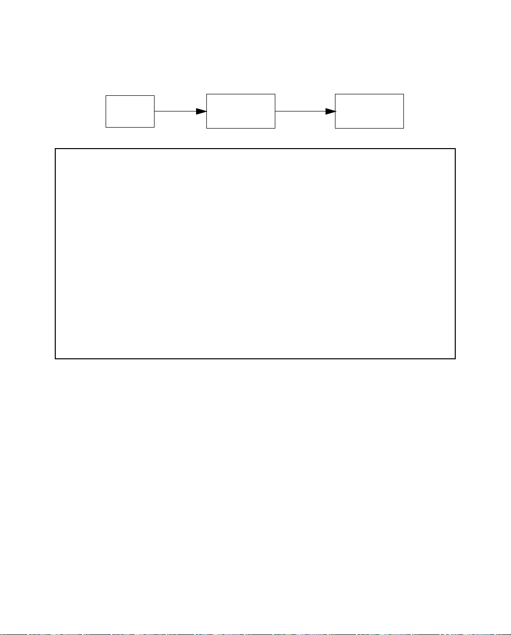
7-58 User’s Reference Guide
TTTThhhheeee SSSSNNNNMMMMPPPP SSSSeeeettttuuuupppp ssssccccrrrreeeeeeeenn
nn
From the Main Menu, select SNMP in the System Configuration screen and press Return. The SNMP Setup
screen appears.
Main
Menu
SNMP Setup
System Name:
System Location:
System Contact:
Read-Only Community String: public
Read/Write Community String: private
Authentication Traps Enable: Off
IP Trap Receivers...
System
Configuration
SNMP
Configure optional SNMP parameters from here.
Follow these steps to configure the first three items in the screen:
1. Select System Name and enter a descriptive name for the Netopia D-Series’s SNMP agent.
2. Select System Location and enter the Netopia D-Series’s physical location (room, floor, building, etc.).
3. Select System Contact and enter the name of the person responsible for maintaining the Netopia
D-Series.
System Name, System Location, and System Contact set the values returned by the Netopia D-Series SNMP
agent for the SysName, SysLocation, and SysContact objects, respectively, in the MIB II system group. Although
optional, the information you enter in these items can help a system administrator manage the network more
efficiently.
CCCCoooommmmmmmmuuuunnnniiiittttyyyy ssssttttrrrriiiinnnnggggss
ss
The Read-Only Community String and the Read/W rite Community String are like passwords that must be used
by an SNMP manager querying or configuring the Netopia D-Series. An SNMP manager using the Read-Only
Community String can examine statistics and configuration information from the Netopia D-Series, but cannot
modify the Netopia D-Series’s configuration. An SNMP manager using the Read/Write Community String can
both examine and modify configuration parameters.
Page 59

Monitoring Tools 7-59
By default, the read-only and read/write community strings are set to “public” and “private,” respectively. You
should change both of the default community strings to values known only to you and trusted system administrators.
To change a community string, select it and enter a new value.
Setting the Read-Only and Read-Write community strings to the empty string will block all SNMP requests to the
Netopia D-Series. (The Netopia D-Series may still send SNMP Traps if those are properly enabled.)
This allows the administrator to block SNMP access to the Netopia D-Series, and to provide more granular
control over the allowed SNMP operations to the Netopia D-Series.
■ Setting only the Read-Write community string to the empty string will block SNMP Set Requests to the
Netopia D-Series, but Get Requests and Get-Next Requests will still be honored using the Read-Only
community string (assuming that is not the empty string).
■ Setting only the Read-Only community string to the empty string will not block Get Requests or Get-Next
Requests since those operations (and Set Requests) are still allowed using the (non-empty) Read-Write
community string.
Even if you decide not to use SNMP, you should change the community strings. This prevents unauthorized
access to the Netopia D-Series through SNMP. For more information on security issues, see “Security” on
page 8-61.
SSSSNNNNMMMMPPPP ttttrrrraaaappppss
ss
An SNMP trap is an informational message sent from an SNMP agent (in this case, the Netopia D-Series) to a
manager. When a manager receives a trap, it may log the trap as well as generate an alert message of its own.
Standard traps generated by the Netopia D-Series include the following:
■ An authentication failure trap is generated when the Netopia D-Series detects an incorrect community
string in a received SNMP packet. Authentication Traps Enable must be On for this trap to be generated.
■ A cold start trap is generated after the Netopia D-Series is reset.
■ An interface down trap (ifDown) is generated when one of the Netopia D-Series’s interfaces, such as a
port, stops functioning or is disabled.
■ An interface up trap (ifUp) is generated when one of the Netopia D-Series’s interfaces, such as a port,
begins functioning.
The Netopia D-Series sends traps using UDP (for IP networks).
You can specify which SNMP managers are sent the IP traps generated by the Netopia D-Series. Up to eight
receivers can be set. You can also review and remove IP traps.
To go to the IP Trap Receivers screen, select IP Trap Receivers. The IP Trap Receivers screen appears.
Page 60

7-60 User’s Reference Guide
IP Trap Receivers
Display/Change IP Trap Receiver...
Add IP Trap Receiver...
Delete IP Trap Receiver...
Return/Enter to modify an existing Trap Receiver.
Navigate from here to view, add, modify and delete IP Trap Receivers.
SSSSeeeettttttttiiiinnnngggg tttthhhheeee IIIIPPPP ttttrrrraaaapppp rrrreeeecccceeeeiiiivvvveeeerrrrss
ss
1. Select Add IP Trap Receiver.
2. Select Receiver IP Address or Domain Name. Enter the IP address or domain name of the SNMP manager
you want to receive the trap.
3. Select Community String if you enabled one in the SNMP Setup screen, and enter the appropriate
password.
4. Select Add Trap Receiver Now and press Return. You can add up to seven more receivers.
VVVViiiieeeewwwwiiiinnnngggg IIIIPPPP ttttrrrraaaapppp rrrreeeecccceeeeiiiivvvveeeerrrrss
ss
To display a view-only table of IP trap receivers, select Display/Change IP Trap Receiver in the IP Trap
Receivers screen.
MMMMooooddddiiiiffffyyyyiiiinnnngggg IIIIPPPP ttttrrrraaaapppp rrrreeeecccceeeeiiiivvvveeeerrrrss
ss
1. To edit an IP trap receiver, select Display/Change IP Trap Receiver in the IP Trap Receivers screen.
2. Select an IP trap receiver from the table and press Return.
3. In the Change IP Trap Receiver screen, edit the information as needed and press Return.
DDDDeeeelllleeeettttiiiinnnngggg IIIIPPPP ttttrrrraaaapppp rrrreeeecccceeeeiiiivvvveeeerrrrss
ss
1. To delete an IP trap receiver, select Delete IP Trap Receiver in the IP Trap Receivers screen.
2. Select an IP trap receiver from the table and press Return.
3. In the dialog box, select Continue and press Return.
Page 61

Security 8-61
CCCChhhhaaaapppptttteeeerrrr 88
SSSSeeeeccccuuuurrrriiiittttyy
The Netopia D-Series provides a number of security features to help protect its configuration screens and your
local network from unauthorized access. Although these features are optional, it is strongly recommended that
you use them.
This section covers the following topics:
■ “Suggested security measures” on page 8-61
■ “User accounts” on page 8-61
■ “Telnet access” on page 8-63
■ “About filters and filter sets” on page 8-64
■ “Filtering tutorial” on page 8-71
■ “Working with Filters and filter sets” on page 8-77
■ “Generic filters” on page 8-86
SSSSuuuuggggggggeeeesssstttteeeedddd sssseeeeccccuuuurrrriiiittttyyyy mmmmeeeeaaaassssuuuurrrreeeess
In addition to setting up user accounts, T elnet access, and filters (all of which are covered later in this chapter),
there are other actions you can take to make the Netopia D-Series and your network more secure:
88
yy
ss
■ Change the SNMP community strings (or passwords). The default community strings are universal and
could easily be known to a potential intruder.
■ Configure the Netopia D-Series through the serial console port to ensure that your communications cannot
be intercepted.
UUUUsssseeeerrrr aaaaccccccccoooouuuunnnnttttss
When you first set up and configure the Netopia D-Series, no passwords are required to access the
configuration screens. Anyone could tamper with the Netopia D-Series’s configuration by simply connecting it to
a console.
However, by adding user accounts, you can protect the most sensitive screens from unauthorized access. User
accounts are composed of name/password combinations that can be given to authorized users.
Caution!
Y ou are strongly encouraged to add protection to the configuration screens. Unprotected screens could allow an
unauthorized user to compromise the operation of your entire network.
Once user accounts are created, users who attempt to access protected screens will be challenged. Users who
enter an incorrect name or password are returned to a screen requesting a name/password combination to
access the Main Menu.
ss
Page 62

8-62 User’s Reference Guide
To set up user accounts, in the System Configuration screen select Security and press Return.
Main
Menu
The Security Options screen appears.
Security Options
Enable Telnet Console Access: Yes
Enable Telnet Access to SNMP Screens: Yes
Show Users...
Add User...
Delete User...
Password for This Screen (11 chars max):
Return/Enter accepts * Tab toggles * ESC cancels.
Set up configuration access options here.
System
Configuration
Security
PPPPrrrrooootttteeeeccccttttiiiinnnngggg tttthhhheeee SSSSeeeeccccuuuurrrriiiittttyyyy OOOOppppttttiiiioooonnnnssss ssssccccrrrreeeeeeeenn
nn
The first screen you should protect is the Security Options screen, because it controls access to the
configuration screens. Access to the Security Options screen can be protected with a password.
Select Password for This Screen in the Security Options screen and enter a password. Make sure this
password is secure and is different from any of the user account passwords.
PPPPrrrrooootttteeeeccccttttiiiinnnngggg tttthhhheeee ccccoooonnnnffffiiiigggguuuurrrraaaattttiiiioooonnnn ssssccccrrrreeeeeeeennnnss
ss
You can protect the configuration screens with user accounts. You can administer the accounts from the
Security Options screen. You can create up to four accounts.
To display a view-only list of user accounts, select Show Users in the Security Options screen.
Page 63

Security 8-63
To add a new user account, select Add User in the Security Options screen and press Return. The Add Name
With Write Access screen appears.
Add Name With Write Access
Enter Name:
Enter Password (11 characters max):
ADD NAME/PASSWORD NOW CANCEL
Follow these steps to configure the new account:
1. Select Enter Name and enter a descriptive name (for example, the user’s first name).
2. Select Enter Password and enter a password.
3. To accept the new name/password combination, select ADD NAME/PASSWORD NOW. To exit the Add
Name With Write Access screen without saving the new account, select CANCEL. You are returned to the
Security Options screen.
To delete a user account, select Delete User to display a list of accounts. Select an account from the list and
press Return to delete it. To exit the list without deleting the selected account, press Escape.
TTTTeeeellllnnnneeeetttt aaaacccccccceeeessssss
Telnet is a TCP/IP service that allows remote terminals to access hosts on an IP network. The Netopia D-Series
supports Telnet access to its configuration screens.
Caution!
You should consider password-protecting or restricting Telnet access to the Netopia D-Series if you suspect
there is a chance of tampering.
To restrict Telnet access, select Security in the Advanced Configuration menu. The Security Options screen will
appear. There are two levels of Telnet restriction available:
To restrict Telnet access to the SNMP screens, select Enable Telnet Access to SNMP Screens and toggle it to
No. (See “SNMP traps” on page 7-59.)
ss
Page 64

8-64 User’s Reference Guide
To restrict Telnet access to all of the configuration screens, select Enable Telnet Console Access and toggle it
to No.
AAAAbbbboooouuuutttt ffffiiiilllltttteeeerrrrssss aaaannnndddd ffffiiiilllltttteeeerrrr sssseeeettttss
ss
Important Note: The Netopia D-Series’s filter sets only work when the unit is in bridge mode. They have no
effect when the unit is in DSU mode.
Security should be a high priority for anyone administering a network connected to the Internet. Using packet
filters to control network communications can greatly improve your network’s security.
The Netopia D-Series’s packet filters are designed to provide security for the Internet connections made to and
from your network. You can customize the Netopia D-Series’s filter sets for a variety of packet filtering
applications. Typically, you use filters to selectively admit or refuse TCP/IP connections from certain remote
networks and specific hosts. You will also use filters to screen particular types of connections. This is
commonly called firewalling your network.
Before creating filter sets, you should read the next few sections to learn more about how these powerful
security tools work.
WWWWhhhhaaaatttt’’’’ssss aaaa ffffiiiilllltttteeeerrrr aaaannnndddd wwwwhhhhaaaatttt’’’’ssss aaaa ffffiiiilllltttteeeerrrr sssseeeetttt??
??
A filter is a rule that lets you specify what sort of data can flow in and out of your network. A particular filter can
be either an input filter—one that is used on data (packets) coming in to your network from the Internet—or an
output filter—one that is used on data (packets) going out from your network to the Internet.
A filter set is a group of filters that work together to check incoming or outgoing data. A filter set can consist of
a combination of input and output filters.
HHHHoooowwww ffffiiiilllltttteeeerrrr sssseeeettttssss wwwwoooorrrrkk
kk
A filter set acts like a team of customs inspectors. Each filter is an inspector through which incoming and
outgoing packages must pass. The inspectors work as a team, but each inspects every package individually.
Each inspector has a specific task. One inspector’s task may be to examine the destination address of all
outgoing packages. That inspector looks for a certain destination—which could be as specific as a street
address or as broad as an entire country—and checks each package’s destination address to see if it matches
that destination.
INSPECTOR
FROM:
TO:
APPROVED
FROM:
TO:
A filter inspects data packets like a customs inspector scrutinizing packages.
FROM:
TO:
Page 65

Security 8-65
FFFFiiiilllltttteeeerrrr pppprrrriiiioooorrrriiiittttyy
yy
Continuing the customs inspectors analogy, imagine the inspectors lined up to examine a package. If the
package matches the first inspector’s criteria, the package is either rejected or passed on to its destination,
depending on the first inspector’s particular orders. In this case, the package is never seen by the remaining
inspectors.
packet
first
filter
match?
yes
pass or
discard?
no
send
to next
filter
discard
(delete)
pass
to network
If the package does not match the first inspector’s criteria, it goes to the second inspector, and so on. You can
see that the order of the inspectors in the line is very important.
For example, let’s say the first inspector’s orders are to send along all packages that come from Rome, and the
second inspector’s orders are to reject all packages that come from France. If a package arrives from Rome,
the first inspector sends it along without allowing the second inspector to see it. A package from Paris is
ignored by the first inspector, rejected by the second inspector, and never seen by the others. A package from
London is ignored by the first two inspectors, so it’s seen by the third inspector.
In the same way, filter sets apply their filters in a particular order. The first filter applied can pass or discard a
packet before that packet ever reaches any of the other filters. If the first filter can neither pass nor discard the
packet (because it cannot match any criteria), the second filter has a chance to pass or reject it, and so on.
Because of this hierarchical structure, each filter is said to have a priority . The first filter has the highest priority,
and the last filter has the lowest priority.
Page 66

8-66 User’s Reference Guide
HHHHoooowwww iiiinnnnddddiiiivvvviiiidddduuuuaaaallll ffffiiiilllltttteeeerrrrssss wwwwoooorrrrkk
kk
As described above, a filter applies criteria to an IP packet and then takes one of three actions:
AAAA ffffiiiilllltttteeeerrrr’’’’ssss aaaaccccttttiiiioooonnnnss
■ Passes the packet to the local or remote network
■ Blocks (discards) the packet
■ Ignores the packet
ss
A filter passes or blocks a packet only if it finds a match after applying its criteria. When no match occurs, the
filter ignores the packet.
AAAA ffffiiiilllltttteeeerrrriiiinnnngggg rrrruuuullllee
ee
The criteria are based on information contained in the packets. A filter is simply a rule that prescribes certain
actions based on certain conditions. For example, the following rule qualifies as a filter:
Block all Telnet attempts that originate from the remote host 199.211.211.17.
This rule applies to Telnet packets that come from a host with the IP address 199.211.211.17. If a match
occurs, the packet is blocked.
Here is what this rule looks like when implemented as a filter on the Netopia D-Series:
+-#--Source IP Addr--Dest IP Addr-----Proto-Src.Port-D.Port--On?-Fwd-+
+--------------------------------------------------------------------+
| 1 199.211.211.17 0.0.0.0 TCP 23 Yes No |
+--------------------------------------------------------------------+
To understand this particular filter, look at the parts of an IP filter.
PPPPaaaarrrrttttssss ooooffff aaaannnn IIIIPPPP ffffiiiilllltttteeeerr
rr
There are two types if filters and filter sets: IP filters and Generic filters. The following discussion applies only to
IP filters and filter sets.
An IP filter consists of criteria based on packet attributes. A typical IP filter can match a packet on any one of
the following attributes:
■ The source IP address (where the packet was sent from)
■ The destination IP address (where the packet is going)
■ The type of higher-layer Internet protocol the packet is carrying, such as TCP or UDP
PPPPoooorrrrtttt nnnnuuuummmmbbbbeeeerrrrss
ss
An IP filter can also match a packet’s port number attributes. The filter can be configured to match the
following:
■ The source port number (the port on the sending host that originated the packet)
■ The destination port number (the port on the receiving host that the packet is destined for)
Page 67

Security 8-67
By matching on a port number, an IP filter can be applied to selected services, such as Telnet, FTP, and World
Wide Web. The tables below show a few common services and their associated port numbers.
Internet service TCP port Internet service TCP port
FTP 20/21 Finger 79
Telnet 23 World Wide Web 80
SMTP (mail) 25 News 144
Gopher 70 rlogin 513
Internet service UDP port Internet service UDP port
Who Is 43 AppleTalk Routing
Maintenance (at-rtmp)
World Wide Web 80 AppleTalk Name Binding
(at-nbp)
SNMP 161 AURP (AppleTalk) 387
TFTP 69 who 513
PPPPoooorrrrtttt nnnnuuuummmmbbbbeeeerrrr ccccoooommmmppppaaaarrrriiiissssoooonnnnss
An IP filter can also use a comparison option to evaluate a packet’s source or destination port number. The
comparison options are:
No Compare: No comparison of the port number specified in the filter with the packet’s port number.
Not Equal To: For the filter to match, the packet’s port number cannot equal the port number specified in the
filter.
Less Than: For the filter to match, the packet’s port number must be less than the port number specified in the
filter.
Less Than or Equal: For the filter to match, the packet’s port number must be less than or equal to the port
number specified in the filter.
Equal: For the filter to match, the packet’s port number must equal the port number specified in the filter.
Greater Than: For the filter to match, the packet’s port number must be greater than the port number specified
in the filter.
ss
202
202
Greater Than or Equal: For the filter to match, the packet’s port number must be greater than or equal to the
port number specified in the filter.
Page 68

8-68 User’s Reference Guide
OOOOtttthhhheeeerrrr ffffiiiilllltttteeeerrrr aaaattttttttrrrriiiibbbbuuuutttteeeess
ss
There are three other attributes to each filter:
■ The filter’s order (i.e., priority) in the filter set
■ Whether the filter is currently active
■ Whether the filter is set to pass (forward) packets or to block (discard) packets
PPPPuuuuttttttttiiiinnnngggg tttthhhheeee ppppaaaarrrrttttssss ttttooooggggeeeetttthhhheeeerr
rr
When you display a filter set, its filters are displayed as rows in a table:
+-#---Source IP Addr---Dest IP Addr-----Proto-Src.Port-D.Port--On?-Fwd-+
+----------------------------------------------------------------------+
| 1 192.211.211.17 0.0.0.0 TCP 0 23 Yes No |
| 2 0.0.0.0 0.0.0.0 TCP NC =6000 Yes No |
| 3 0.0.0.0 0.0.0.0 ICMP -- -- Yes Yes |
| 4 0.0.0.0 0.0.0.0 TCP NC >1023 Yes Yes |
| 5 0.0.0.0 0.0.0.0 UDP NC >1023 Yes Yes |
| |
| |
| |
| |
| |
| |
| |
| |
| |
| |
| |
+----------------------------------------------------------------------+
The table’s columns correspond to each filter’s attributes:
#: The filter’s priority in the set. Filter number 1, with the highest priority, is first in the table.
Source IP Addr: The packet source IP address to match.
Dest IP Addr: The packet destination IP address to match.
Proto: The protocol to match. This can be entered as a number (see the table below) or as TCP or UDP if those
protocols are used.
Protocol Number to use Full name
N/A 0 Ignores protocol type
ICMP 1 Internet Control Message Protocol
TCP 6 Transmission Control Protocol
UDP 17 User Datagram Protocol
Page 69

Security 8-69
Src. Port: The source port to match. This is the port on the sending host that originated the packet.
D. Port: The destination port to match. This is the port on the receiving host for which the packet is intended.
On?: Displays Yes when the filter is in effect or No when it is not.
Fwd: Shows whether the filter forwards (Yes) a packet or discards (No) it when there’s a match.
FFFFiiiilllltttteeeerrrriiiinnnngggg eeeexxxxaaaammmmpppplllleeee ####11
11
Returning to our filtering rule example from above (see page 8-67), look at how a rule is translated into an IP
filter. Start with the rule, then fill in the filter’s attributes:
1. The rule you want to implement as a filter is:
Block all Telnet attempts that originate from the remote host 199.211.211.17.
2. The host 199.211.211.17 is the source of the Telnet packets you want to block, while the destination
address is any IP address.
The Source IP Address Mask and Destination IP Address Mask fields indicate how many bits in the
corresponding address the filter rule applies to.
How these IP addresses are masked determines what the final match will be, although the mask is not
displayed in the table that displays the filter sets (you set it when you create the filter). In fact, since the
mask for the destination IP address is 0.0.0.0, the address for Dest IP Addr could have been anything. The
mask for Source IP Addr must be 255.255.255.255 since an exact match is desired.
■ Source IP Addr = 199.211.211.17
■ Source IP address mask = 255.255.255.255
■ Dest IP Addr = 0.0.0.0
■ Destination IP address mask = 0.0.0.0
3. Using the tables on page 8-67, find the destination port and protocol numbers (the Telnet port):
■ Proto = TCP (or 6)
■ D. Port = 23
4. The filter should be enabled and instructed to block the Telnet packets containing the source address
shown in step 2:
■ On? = Yes
■ Fwd = No
This four-step process is how we produced the following filter from the original rule:
+-#---Source IP Addr---Dest IP Addr-----Proto-Src.Port-D.Port--On?-Fwd-+
+----------------------------------------------------------------------+
| 1 192.211.211.17 0.0.0.0 ANY -- -- Yes No |
| |
+----------------------------------------------------------------------+
Page 70

8-70 User’s Reference Guide
FFFFiiiilllltttteeeerrrriiiinnnngggg eeeexxxxaaaammmmpppplllleeee ####22
22
Suppose a filter is configured to block all incoming IP packets with the source IP address of 200.233.14.0,
regardless of the type of connection or its destination. The filter would look like this:
+-#---Source IP Addr---Dest IP Addr-----Proto-Src.Port-D.Port--On?-Fwd-+
+----------------------------------------------------------------------+
| 1 200.233.14.0 0.0.0.0 ANY -- -- Yes No |
| |
+----------------------------------------------------------------------+
This filter blocks any packets coming from a remote network with the IP network address 200.233.14.0. The 0
at the end of the address signifies any host on the class C IP network 200.233.14.0. If, for example, the filter
is applied to a packet with the source IP address 200.233.14.5, it will block it.
In this case, the mask, which does not appear in the table, must be set to 255.255.255.0. This way, all
packets with a source address of 200.233.14.x will be matched correctly, no matter what the final address byte
is.
Note: The protocol attribute for this filter is 0 by default. This tells the filter to ignore the IP protocol or type of
IP packet.
DDDDeeeessssiiiiggggnnnn gggguuuuiiiiddddeeeelllliiiinnnneeeess
ss
Careful thought must go into designing a new filter set. You should consider the following guidelines:
■ Be sure the filter set’s overall purpose is clear from the beginning. A vague purpose can lead to a faulty
set, and that can actually make your network less secure.
■ Be sure each individual filter’s purpose is clear.
■ Determine how filter priority will affect the set’s actions. Test the set (on paper) by determining how the
filters would respond to a number of different hypothetical packets.
■ Consider the combined effect of the filters. If every filter in a set fails to match on a particular packet, the
packet is:
■ Passed if all the filters are configured to discard (not forward)
■ Discarded if all the filters are configured to pass (forward)
■ Discarded if the set contains a combination of pass and discard filters
DDDDiiiissssaaaaddddvvvvaaaannnnttttaaaaggggeeeessss ooooffff ffffiiiilllltttteeeerrrrss
ss
Although using filter sets can greatly enhance network security, there are disadvantages:
■ Filters are complex. Combining them in filter sets introduces subtle interactions, increasing the likelihood
of implementation errors.
■ Enabling a large number of filters can have a negative impact on performance. Processing of packets will
take longer if they have to go through many checkpoints.
■ Too much reliance on packet filters can cause too little reliance on other security methods. Filter sets are
not a substitute for password protection, effective safeguarding of passwords, caller ID, the “must match”
option in the answer profile, PAP or CHAP in connection profiles, callback, and general awareness of how
Page 71

your network may be vulnerable.
Security 8-71
AAAAnnnn aaaapppppppprrrrooooaaaacccchhhh ttttoooo uuuussssiiiinnnngggg ffffiiiilllltttteeeerrrrss
The ultimate goal of network security is to prevent unauthorized access to the network without compromising
authorized access. Using filter sets is part of reaching that goal.
Each filter set you design will be based on one of the following approaches:
■ “That which is not expressly permitted is prohibited.”
■ “That which is not expressly prohibited is permitted.”
The first rule is far more secure, and is the best approach to filter design. It is far easier (and more secure) to
allow in or out only certain services and deny anything else. If the other rule is used, you would have to figure
out everything that you want to disallow, now and in the future.
FFFFiiiilllltttteeeerrrriiiinnnngggg ttttuuuuttttoooorrrriiiiaaaall
GGGGeeeennnneeeerrrraaaallll ffffiiiilllltttteeeerrrriiiinnnngggg tttteeeerrrrmmmmss
Filter rule: A filter set is comprised of individual filter rules.
Filter set: A grouping of individual filter rules.
Firewall: A component or set of components that restrict access between a protected network and the Internet,
or between two networks.
Host: A workstation on the network.
Packet: Unit of communication on the Internet.
ss
ll
ss
Packet filter: Packet filters allow or deny packets based on source or destination IP addresses, TCP or UDP
ports, or the TCP ACK bit.
Port: A number that defines a particular type of service.
BBBBaaaassssiiiicccc IIIIPPPP ppppaaaacccckkkkeeeetttt ccccoooommmmppppoooonnnneeeennnnttttss
All IP packets contain the same basic header information, as follows:
ss
Source IP Address 163.176.132.18
Destination IP Address 163.176.4.27
Source Port 2541
Destination Port 80
Protocol TCP
ACK Bit Yes
DATA User Data
Page 72

8-72 User’s Reference Guide
This header information is what the packet filter uses to make filtering decisions. It is important to note that an
IP packet filter does not look into the IP data stream (the User Data from above) to make filtering decisions.
Generic filters can look into the data.
BBBBaaaassssiiiicccc pppprrrroooottttooooccccoooollll ttttyyyyppppeeeess
TCP: Transmission Control Protocol. TCP provides reliable packet delivery and has a retransmission
mechanism (so packets are not lost). RFC 793 is the specification for TCP.
UDP: User Datagram Protocol. Unlike TCP, UDP does not guarantee reliable, sequenced packet delivery. If data
does not reach its destination, UDP does not retransmit the data. RFC 768 is the specification for UDP.
There are many more ports defined in the Assigned Addresses RFC. The tables on page 8-66 show some of
these port assignments.
FFFFiiiilllltttteeeerrrr LLLLooooggggiiiicc
Filter design is a test of logic, and filter rule ordering is critical. If a packet is passed through a series of filter
rules and then the packet matches a rule, the appropriate action is taken. The packet will not pass through the
remainder of the filter rules.
For example, if you had the following filter set...
Allow WWW access;
Allow FTP access;
Allow SMTP access;
Deny all other packets.
and a packet goes through these rules destined for FTP, the packet would pass through the first rule (WWW), go
through the second rule (FTP), and match this rule; the packet is allowed through.
If you had this filter set for example....
cc
ss
Allow WWW access;
Allow FTP access;
Deny FTP access;
Deny all other packets.
and a packet goes through these rules destined for FTP, the packet would pass through the first filter rule
(WWW), match the second rule (FTP), and the packet is allowed through. Even though the next rule is to deny all
FTP traffic, the FTP packet will never make it to this rule.
BBBBiiiinnnnaaaarrrryyyy rrrreeeepppprrrreeeesssseeeennnnttttaaaattttiiiioooonn
It is easiest when doing filtering to convert the IP address and mask in question to binary. This will allow you to
perform the logical AND to determine whether a packet matches a filter rule.
LLLLooooggggiiiiccccaaaallll AAAANNNNDDDD ffffuuuunnnnccccttttiiiioooonn
When a packet is compared (in most cases) a logical AND function is performed. First the IP addresses and
subnet masks are converted to binary and then combined with AND. The rules for the logical use of AND are as
follows:
nn
nn
Page 73

0 AND 0 = 0
0 AND 1 = 0
1 AND 0 = 0
1 AND 1 = 1
For example:
Filter rule:
Deny
IP: 163.176.1.15BINARY: 10100011.10110000.00000001.00001111
Mask: 255.255.255.255BINARY:11111111.11111111.11111111.11111111
Incoming Packet:
IP 163.176.1.15BINARY: 10100011.10110000.00000001.00001111
If you put the incoming packet and subnet mask together with AND, the result is:
10100011.10110000.00000001.00001111
which matches the IP address in the filter rule and the packet is denied.
Security 8-73
IIIImmmmpppplllliiiieeeedddd rrrruuuulllleeeess
With a given set of filter rules, there is an Implied rule that may or may not be shown to the user. The implied
rule tells the filter set what to do with a packet that does not match any of the filter rules. An example of implied
rules is as follows:
EEEEssssttttaaaabbbblllliiiisssshhhheeeedddd ccccoooonnnnnnnneeeeccccttttiiiioooonnnnss
The TCP header contains one bit called the ACK bit (or TCP Ack bit). This ACK bit appears only with TCP, not
UDP. The ACK bit is part of the TCP mechanism that guaranteed the delivery of data. The ACK bit is set
whenever one side of a connection has received data from the other side. Only the first TCP packet will not have
the ACK bit set; once the TCP connection is in place, the remainder of the TCP packets with have the ACK bit
set.
The ACK bit is helpful for filter design and reduces the number of potential filter rules. A filter rule could be
created just allowing incoming TCP packets with the ACK bit set, since these packets had to be originated from
the local network.
ss
Implied Meaning
Y+Y+Y=N If all filter rules are YES, the implied rule is NO.
N+N+N=Y If all filter rules are NO, the implied rule is YES.
Y+N+Y=N If a mix of YES and NO filters, the implied rule is NO.
ss
Page 74

8-74 User’s Reference Guide
EEEExxxxaaaammmmpppplllleeee IIIIPPPP FFFFiiiilllltttteeeerrrr sssseeeetttt ssssccccrrrreeeeeeeenn
This is an example of the Netopia Filter set screen:
Change Input Filter 1
Enabled: Yes
Forward: No
Type... IP
Source IP Address: 0.0.0.0
Source IP Address Mask: 0.0.0.0
Dest. IP Address: 0.0.0.0
Dest. IP Address Mask: 0.0.0.0
Protocol Type: TCP
Source Port Compare... No Compare
Source Port ID: 0
Dest. Port Compare... Equal
Dest. Port ID: 2000
Established TCP Conns. Only: No
Return/Enter accepts * Tab toggles * ESC cancels.
Enter the packet specific information for this filter.
FFFFiiiilllltttteeeerrrr bbbbaaaassssiiiiccccss
In the source or destination IP address fields, the IP address that is entered must be the network address of
the subnet. A host address can be entered, but the applied subnet mask must be 32 bits (255.255.255.255).
ss
nn
EEEExxxxaaaammmmpppplllleeee nnnneeeettttwwwwoooorrrrkk
kk
Incoming
Packet Filter
Netopia
Internet
IP: 200.1.1.??
DATA
Page 75

Security 8-75
EEEExxxxaaaammmmpppplllleeee IIIIPPPP ffffiiiilllltttteeeerrrrss
EEEExxxxaaaammmmpppplllleeee 1111
Write a filter rule that blocks the class C subnet represented by 200.1.1.0/25 from accessing the net.
Incoming packet has the source address of 200.1.1.28
To determine if the packet will match on the filter, perform a Boolean AND on the source IP address and the
filter’s source IP mask:
IP Address Binary Representation of
200.1.1.28 00011100 (Source address in incoming IP packet)
AND
ss
Filter Rule: 200.1.1.0 (Source IP Network Address)
255.255.255.128 (Source IP Mask)
Forward = No (What happens on match)
the last byte of the IP
address
255.255.255.128 10000000 (Perform the logical AND)
00000000 (Logical AND result)
This incoming IP packet has a source IP address that matches the network address in the Source IP Address
field (whose last byte is binary 00000000) in the Netopia D-Series. This will not forward this packet.
EEEExxxxaaaammmmpppplllleeee 2222
Incoming packet has the source address of 200.1.1.184.
Filter Rule: 200.1.1.0 (Source IP Network Address)
255.255.255.128 (Source IP Mask)
Forward = No (What happens on match)
IP Address Binary Representation
200.1.1.184 10111000 (Source address in incoming IP packet)
AND
Page 76

8-76 User’s Reference Guide
255.255.255.128 10000000 (Perform the logical AND)
10000000 (Logical AND result)
This incoming IP packet (10000000) has a source IP address that does not match the network address in the
Source IP Address field (00000000) in the Netopia D-Series. This rule will forward this packet because the
packet does not match.
EEEExxxxaaaammmmpppplllleeee 33
Incoming packet has the source address of 200.1.1.184.
Since the Source IP Network Address in the Netopia D-Series’s filter rule is 01100000 (=96 decimal), and the
source IP address after the logical AND is 1011000, this rule does not match and this packet will be passed.
EEEExxxxaaaammmmpppplllleeee 44
33
Filter Rule: 200.1.1.96 (Source IP Network Address)
255.255.255.240 (Source IP Mask)
Forward = No (What happens on match)
IP Address Binary Representation of
last byte
200.1.1.184 10111000 (Source address in incoming IP packet)
AND
255.255.255.240 11110000 (Perform the logical AND)
10110000 (Logical AND result)
44
Filter Rule: 200.1.1.96 (Source IP Network Address)
255.255.255.240 (Source IP Mask)
Forward = No (What happens on match)
Incoming packet has the source address of 200.1.1.104.
IP Address Binary Representation
200.1.1.104 01101000 (Source address in incoming IP packet)
AND
Page 77

Security 8-77
255.255.255.240 11110000 (Perform the logical AND)
01100000 (Logical AND result)
Since the Source IP Network Address in the Netopia D-Series’s filter rule is 01100000 (=96 decimal), and the
source IP address after the logical AND is 01100000, this rule does match and this packet will not be passed.
EEEExxxxaaaammmmpppplllleeee 55
Incoming packet has the source address of 200.1.1.96.
Since the Source IP Network Address in the Netopia D-Series is 01100000, and the source IP address after the
logical AND is 01100000, this rule does match and this packet will NOT be passed. This rule masks off a
single IP address.
55
Filter Rule: 200.1.1.96 (Source IP Network Address)
255.255.255.255 (Source IP Mask)
Forward = No (What happens on match)
IP Address Binary Representation
200.1.1.96 01100000 (Source address in incoming IP packet)
AND
255.255.255.255 11111111 (Perform the logical AND)
01100000 (Logical AND result)
WWWWoooorrrrkkkkiiiinnnngggg wwwwiiiitttthhhh FFFFiiiilllltttteeeerrrrssss aaaannnndddd ffffiiiilllltttteeeerrrr sssseeeettttss
This section covers Filters and filter sets.
Main
Menu
To work with filters and filter sets, begin by accessing the filter set screens.
Note: Make sure you understand how filters work before attempting to use them. Read the section “About
filters and filter sets,” beginning on page 8-64.
ss
System
Configuration
Filter
Sets
Page 78

8-78 User’s Reference Guide
Filter Sets
Add Filter Set...
Display/Change Filter Set...
Delete Filter Set...
Return/Enter to modify an existing Filter Set.
Set Up IP Filter Sets (Firewalls) from this and the following Menus.
The procedure for creating and maintaining filter sets is as follows:
1. Add a new filter set.
2. Create the filters for the new filter set.
3. View, change, or delete individual filters and filter sets.
The following sections explain how to execute these steps.
AAAAddddddddiiiinnnngggg aaaa ffffiiiilllltttteeeerrrr sssseeeett
tt
You can create up to 255 filter rules. You can use them in any combination of input or output in up to eight filter
sets.
To add a new filter set, select Add Filter Set in the Filter Sets screen and press Return. The Add Filter Set
screen appears.
Page 79

Add Filter Set...
Filter Set Name: Filter Set 1
ADD FILTER SET CANCEL
Configure the Filter Set name and its associated Filters.
Security 8-79
NNNNaaaammmmiiiinnnngggg aaaa nnnneeeewwww ffffiiiilllltttteeeerrrr sssseeeett
tt
All new filter sets have a default name. The first filter set you add will be called Filter Set 1, the next filter will be
Filter Set 2, and so on.
To give a new filter set a different name, select Filter Set Name and enter a new name for the filter set.
To save the filter set, select ADD FILTER SET. The saved filter set is empty (contains no filters), but you can
return to it later to add filters (see “Modifying filter sets” on page 8-85). Or you can add filters to your new set
before saving it (see “Adding filters to a filter set” on page 8-80).
T o leave the Add Filter Set screen without saving the new filter set Select CANCEL. You are returned to the Filter
Sets screen.
Page 80

8-80 User’s Reference Guide
IIIInnnnppppuuuutttt aaaannnndddd oooouuuuttttppppuuuutttt ffffiiiilllltttteeeerrrrssss————ssssoooouuuurrrrcccceeee aaaannnndddd ddddeeeessssttttiiiinnnnaaaattttiiiioooonn
There are two kinds of filters you can add to a filter set: input and output. Input filters check packets received
from the Internet, destined for your network. Output filters check packets transmitted from your network to the
Internet.
packet
WAN
output filter
The Netopia D7100
Packets in the Netopia D-Series pass through an input filter if they originate in the WAN and through an output filter if they’re
being sent out to the WAN.
The process for adding input and output filters is exactly the same. The main difference between the two
involves their reference to source and destination. From the perspective of an input filter, your local network is
the destination of the packets it checks, and the remote network is their source. From the perspective of an
output filter, your local network is the source of the packets, and the remote network is their destination.
nn
input filter
LAN
packet
Type of filter “Source” means “Destination” means
Input filter The remote network The local network
Output filter The local network The remote network
AAAAddddddddiiiinnnngggg ffffiiiilllltttteeeerrrrssss ttttoooo aaaa ffffiiiilllltttteeeerrrr sssseeeett
In this section you’ll learn how to add an input filter to a filter set. Adding an output filter works exactly the same
way, providing you keep the different source and destination perspectives in mind.
To add an input filter, navigate to the Display/Change Filter Set screen and select Display/Change Filter Set.
Main
Menu
A popup menu displays a list of the filter sets you have created.
Select the one you want to edit.
tt
System
Configuration
Filter
Sets
Display/Change
Filter Set
Page 81

The Display/Change Filter Set screen appears.
Display/Change Filter Set...
Filter Set Name: Filter Set 1
Add Input Filter to Filter Set...
Display/Change Input Filter...
Delete Input Filter...
Move Input Filter...
Add Output Filter to Filter Set...
Display/Change Output Filter...
Delete Output Filter...
Move Output Filter...
To add an input filter, select Add Input Filter to Filter Set.
The Add Filter screen appears. (To add an output filter, select Add Output Filter.)
Security 8-81
Add Filter
Enabled: Yes
Forward: No
Type... IP
Source IP Address: 0.0.0.0
Source IP Address Mask: 0.0.0.0
Dest. IP Address: 0.0.0.0
Dest. IP Address Mask: 0.0.0.0
Protocol Type: UDP
Source Port Compare... No Compare
Source Port ID: 0
Dest. Port Compare... No Compare
Dest. Port ID: 0
ADD THIS FILTER NOW CANCEL
Return/Enter to set comparison of packet Port ID and Filter Port ID.
Enter the IP specific information for this filter.
1. T o make the filter active in the filter set, select Enabled and toggle it to Yes. If Enabled is toggled to No, the
filter can still exist in the filter set, but it will have no effect.
2. If you want the filter to forward packets that match its criteria to the destination IP address, select Forward
and toggle it to Yes. If Forward is toggled to No, packets matching the filter’s criteria will be discarded.
Page 82

8-82 User’s Reference Guide
3. Select Type. A popup menu offers the option of either IP or Generic. If you choose IP , continue with the next
step. If you choose Generic filtering, skip to the section “Generic filters” on page 8-86.
Warning: Changing the filter Type clears the filter values if any were previously entered.
4. Select Source IP Address and enter the source IP address this filter will match on. You can enter a subnet
or a host address.
5. Select Source IP Address Mask and enter a mask for the source IP address. This allows you to further
modify the way the filter will match on the source address. Enter 0.0.0.0 to force the filter to match on all
source IP addresses, or enter 255.255.255.255 to match the source IP address exclusively.
6. Select Dest. IP Address and enter the destination IP address this filter will match on. You can enter a
subnet or a host address.
7. Select Dest. IP Address Mask and enter a mask for the destination IP address. This allows you to further
modify the way the filter will match on the destination address. Enter 0.0.0.0 to force the filter to match on
all destination IP addresses.
8. Select Protocol Type and enter ICMP, TCP, UDP, Any, or the number of another IP transport protocol (see
the table on page 8-68).
Note: If Protocol Type is set to TCP or UDP , the settings for port comparison that you configure in steps 9.
and 10. will appear. These settings only take effect if the Protocol Type is TCP or UDP.
9. Select Source Port Compare and choose a comparison method for the filter to use on a packet’s source
port number. Then select Source Port ID and enter the actual source port number to match on (see the
table on page 8-67).
10. Select Dest. Port Compare and choose a comparison method for the filter to use on a packet’s destination
port number. Then select Dest. Port ID and enter the actual destination port number to match on (see the
table on page 8-67).
11. When you are finished configuring the filter, select ADD THIS FILTER NOW to save the filter in the filter set.
Select CANCEL to discard the filter and return to the Add Filter Set screen.
Page 83

Security 8-83
MMMMoooovvvviiiinnnngggg ffffiiiilllltttteeeerrrrss
ss
The Move Input/Output Filter permits reordering of rules in a filter set.
+#----Source IP Addr---Dest IP Addr-----Proto-Src.Port-D.Port--On?-Fwd-+
+----------------------------------------------------------------------+
| 1 1.1.1.1 0.0.0.0 ANY -- -- Yes No |
| 2 000000000000 000000000000 0 = No Yes No |
| 3 4.4.4.4 0.0.0.0 ANY -- -- Yes No |
| 4 3.3.3.3 0.0.0.0 ANY -- -- Yes No |
| 5 5.5.5.5 0.0.0.0 ANY -- -- Yes No |
| |
| |
| |
| |
| |
| |
| |
| |
| |
| |
| |
+----------------------------------------------------------------------+
Arrows move filter. RETURN/ENTER to accept new filter location. ESC aborts.
All operations are done from a single popup.
■ In the Display/Change Filter Set screen, select Move Input Filter (or Move Output Filter). A selection mode
popup appears. In this mode you scroll to the rule you want to move and press Return on a rule to select it
for moving.
The help text tells you what is expected.
■ After pressing Return you are in Move mode. Arrow keys move the selected rule up or down. When you
press Return again the rule is put in the new location permanently and the popup is dismissed. You can
press Escape at any time in the popup to abort the move and restore the filter set to its original ordering.
VVVViiiieeeewwwwiiiinnnngggg ffffiiiilllltttteeeerrrrss
ss
To display a view-only table of input (output) filters, select Display/Change Input Filter or Display/Change
Output Filter in the Display/Change Filter Set screen.
MMMMooooddddiiiiffffyyyyiiiinnnngggg ffffiiiilllltttteeeerrrrss
ss
To modify a filter, select Display/Change Input Filter or Display/Change Output Filter in the Display/Change
Filter Set screen to display a table of filters.
Select a filter from the table and press Return. The Change Filter screen appears. The parameters in this
screen are set in the same way as the ones in the Add Filter screen (see “Adding filters to a filter set” on
page 8-80).
Page 84

8-84 User’s Reference Guide
Change Filter
Enabled: No
Forward: No
Source IP Address: 0.0.0.0
Source IP Address Mask: 0.0.0.0
Dest. IP Address: 0.0.0.0
Dest. IP Address Mask: 0.0.0.0
Protocol Type: 0
Source Port Compare... No Compare
Source Port ID: 0
Dest. Port Compare... No Compare
Dest. Port ID: 0
Enter the IP specific information for this filter.
DDDDeeeelllleeeettttiiiinnnngggg ffffiiiilllltttteeeerrrrss
ss
T o delete a filter , select Delete Input Filter or Delete Output Filter in the Add Filter Set screen to display a table
of filters.
Select the filter from the table and press Return to delete it. Press Escape to exit the table without deleting the
filter.
VVVViiiieeeewwwwiiiinnnngggg ffffiiiilllltttteeeerrrr sssseeeettttss
ss
To display a view-only list of filter sets, select Display/Change Filter Set in the Filter Sets screen.
Page 85

Security 8-85
MMMMooooddddiiiiffffyyyyiiiinnnngggg ffffiiiilllltttteeeerrrr sssseeeettttss
ss
To modify a filter set, select Display/Change Filter Set in the Filter Sets screen to display a list of filter sets.
Select a filter set from the list and press Return. The Change Filter Set screen appears. The items in this
screen are the same as the ones in the Add Filter screen (see “Adding filters to a filter set” on page 8-80).
Display/Change Filter Set...
Filter Set Name: Filter Set 1
Add Input Filter to Filter Set...
Display/Change Input Filter...
Delete Input Filter...
Move Input Filter...
Add Output Filter to Filter Set...
Display/Change Output Filter...
Delete Output Filter...
Move Output Filter...
DDDDeeeelllleeeettttiiiinnnngggg aaaa ffffiiiilllltttteeeerrrr sssseeeett
tt
Note: If you delete a filter set, all of the filters it contains are deleted as well. To reuse any of these filters in
another set, before deleting the current filter set you’ll have to note their configuration and then recreate them.
To delete a filter set, select Delete Filter Set in the Filter Sets screen to display a list of filter sets.
Select a filter set from the list and press Return to delete it. Press Escape to exit the list without deleting the
filter set.
Page 86

8-86 User’s Reference Guide
GGGGeeeennnneeeerrrriiiicccc ffffiiiilllltttteeeerrrrss
ss
If you chose Generic filtering in step 3. on page 8-82, the Add Filter screen changes as shown:
Add Filter
Enabled: Yes
Forward: No
Type... Generic
Value: 000000000000
Mask: 000000000000
Offset: 0
Compare: Equal
Chain to Next Filter: No
ADD THIS FILTER NOW CANCEL
Enter the IP specific information for this filter.
Note: Generic filters are more complicated to use than IP filters. If you plan to filter only IP traffic, we
recommend that you use IP filters instead.
Generic filters are performed on packets as a whole, after layer 2 encapsulation is removed (ATM-FUNI or Frame
Relay). You configure them in much the same way as the IP version.
■ The Value and Mask fields can be 8 bytes in length, two characters per byte, so for example a MAC
address is 6 bytes: 00-00-C5-60-34-74.
The Value, Mask, and Offset are used together to determine if the packet matches the filter. The Value is
logically ANDed with the Mask; the Offset specifies the number of bytes into the packet where the Value
ANDed with the Mask must be present. If these match, the filter matches the packet.
■ Several Generic Filters can be ANDed together by toggling Chain to Next Filter to Yes. In this case all the
filters chained must match the packet, and the last filter in the chain determines the Forwarding decision.
The Compare field works as it does in the Filter version
Page 87

Security 8-87
AAAAbbbboooouuuutttt ggggeeeennnneeeerrrriiiicccc ffffiiiilllltttteeeerrrrss
ss
One of the more difficult aspects of writing Generic filter sets is determining how many bytes into the packet
(the Offset) the value you want to test is. In order to find the Offset value a good understanding of packet
formats is helpful. The following figure depicts a typical packet format structure for purposes of this example.
Destination
Address
Source
Address
Frame Type Frame Data CRC
6 octets 6 octets 2 octets 64 - 1500 octets 4 octets
0 1 2 3
0 1 2 3 4 5 6 7 8 9 0 1 2 3 4 5 6 7 8 9 0 1 2 3 4 5 6 7 8 9 0 1
+-+-+-+-+-+-+-+-+-+-+-+-+-+-+-+-+-+-+-+-+-+-+-+-+-+-+-+-+-+-+-+-+
|Version| IHL |Type of Service| Total Length |
+-+-+-+-+-+-+-+-+-+-+-+-+-+-+-+-+-+-+-+-+-+-+-+-+-+-+-+-+-+-+-+-+
| Identification |Flags| Fragment Offset |
+-+-+-+-+-+-+-+-+-+-+-+-+-+-+-+-+-+-+-+-+-+-+-+-+-+-+-+-+-+-+-+-+
| Time to Live | Protocol | Header Checksum |
+-+-+-+-+-+-+-+-+-+-+-+-+-+-+-+-+-+-+-+-+-+-+-+-+-+-+-+-+-+-+-+-+
| Source Address |
+-+-+-+-+-+-+-+-+-+-+-+-+-+-+-+-+-+-+-+-+-+-+-+-+-+-+-+-+-+-+-+-+
| Destination Address |
+-+-+-+-+-+-+-+-+-+-+-+-+-+-+-+-+-+-+-+-+-+-+-+-+-+-+-+-+-+-+-+-+
| Options | Padding |
+-+-+-+-+-+-+-+-+-+-+-+-+-+-+-+-+-+-+-+-+-+-+-+-+-+-+-+-+-+-+-+-+
| data |
+-+-+-+-+-+-+-+-+-+-+-+-+-+-+-+-+-+-+-+-+-+-+-+-+-+-+-+-+-+-+-+-+
IP Header Format
Note that one tick mark represents one bit position.
0 1 2 3
0 1 2 3 4 5 6 7 8 9 0 1 2 3 4 5 6 7 8 9 0 1 2 3 4 5 6 7 8 9 0 1
+-+-+-+-+-+-+-+-+-+-+-+-+-+-+-+-+-+-+-+-+-+-+-+-+-+-+-+-+-+-+-+-+
| Source Port | Destination Port |
+-+-+-+-+-+-+-+-+-+-+-+-+-+-+-+-+-+-+-+-+-+-+-+-+-+-+-+-+-+-+-+-+
| Sequence Number |
+-+-+-+-+-+-+-+-+-+-+-+-+-+-+-+-+-+-+-+-+-+-+-+-+-+-+-+-+-+-+-+-+
| Acknowledgment Number |
+-+-+-+-+-+-+-+-+-+-+-+-+-+-+-+-+-+-+-+-+-+-+-+-+-+-+-+-+-+-+-+-+
| Data | |U|A|P|R|S|F| |
| Offset| Reserved |R|C|S|S|Y|I| Window |
| | |G|K|H|T|N|N| |
+-+-+-+-+-+-+-+-+-+-+-+-+-+-+-+-+-+-+-+-+-+-+-+-+-+-+-+-+-+-+-+-+
| Checksum | Urgent Pointer |
+-+-+-+-+-+-+-+-+-+-+-+-+-+-+-+-+-+-+-+-+-+-+-+-+-+-+-+-+-+-+-+-+
| Options | Padding |
+-+-+-+-+-+-+-+-+-+-+-+-+-+-+-+-+-+-+-+-+-+-+-+-+-+-+-+-+-+-+-+-+
| data |
+-+-+-+-+-+-+-+-+-+-+-+-+-+-+-+-+-+-+-+-+-+-+-+-+-+-+-+-+-+-+-+-+
TCP Header Format
Note that one tick mark represents one bit position.
Observe that the first six bytes of the packet (frame) are used to indicate the destination MAC address and the
next six are used define the source MAC address. So, for example, to write a Generic filter set that would block
all incoming traffic to Mac address 00-00-c8-e3-95 you could create a filter rule like this:
Page 88

8-88 User’s Reference Guide
Add Input Filter
Enabled: Yes
Forward: No
Type... Generic
Value: 0000C8E395000000
Mask: FFFFFFFFFF000000
Offset: 6
Compare: Equal
Chain to Next Filter: No
ADD THIS FILTER NOW CANCEL
Enter the packet specific information for this filter.
Note the Offset is set to look at a value six bytes into the packet, the Value is 0000C8E395000000 and
the Mask is set to match only the hexidecimal digits we're interested in -- the ones that represent the MAC
address.
■ The next item that's commonly evaluated in a Generic filter is the frame type. The frame type is located at
an offset of twelve bytes. For IP packets it has a value of 0800 (hex) and for ARP the value is 0806 (hex).
So a filter set summary to block all incoming IP and ARP packets looks like this:
+-#----Value-------------Mask--------------Offst-Compare--Chain---On?-Fwd-+
+-------------------------------------------------------------------------+
| 1 0800000000000000 FFFF000000000000 12 = No Yes No |
| 2 0806000000000000 FFFF000000000000 12 = No Yes No |
| |
| |
A filter set blocking all incoming IPX requires two filter rules. One to verify the byte with offset of 12 bytes is
less than 600 (hex) ANDed (chained with) a filter that verifies the byte offset by 14 is not equal to FFFF.
■ The filter set should look like this (with the first filter rule's chain field set to “Yes” because the packet has
to match both rules to be qualified as an IPX packet.)
+-#----Value-------------Mask--------------Offst-Compare--Chain---On?-Fwd-+
+-------------------------------------------------------------------------+
| 1 0600000000000000 FFFF000000000000 12 < Yes Yes |
| 2 FFFF000000000000 FFFF000000000000 14 = No Yes No |
| |
Page 89

Security 8-89
The following example further illustrates filter rule chaining, different sized masks and the full 8 bytes of the
Value field.
Create a filter set designed to block telnet access from a given external node (the example below uses
176.163.52.18) to a given internal node (176.163.107.254).
The filter rule summary (input) should look like this:
+-#----Value-------------Mask--------------Offst-Compare--Chain---On?-Fwd-+
+-------------------------------------------------------------------------+
| 1 0500000000000000 0F00000000000000 14 = No Yes No |
| 2 0800000000000000 FFFF000000000000 12 = Yes Yes |
| 3 0600000000000000 FF00000000000000 23 = Yes Yes |
| 4 B0A33412B0A3B0FE FFFFFFFFFFFFFFFF 26 = Yes Yes |
| 5 0017000000000000 FFFF000000000000 36 = No Yes No |
| |
■ Filter #1 checks that the IHL has a size of 5. This is a useful security check to verify a potential hacker has
not padded the packet with options that would then throw off following filter rule checks on bytes further
into the packet.
■ Filter #2 checks the incoming packet is IP.
■ Filter #3 checks that the packet is using TCP.
■ Filter #4 simultaneously checks the source IP address is 176.163.52.18 (= B0A33412 in hex) and the
destination IP address is 176.163.107.254 (= B0A3B0FE in hex).
■ Filter #5 checks the TCP port address is telnet (= 23 decimal = 17 hex).
Note: This filter set is presented only to illustrate how Generic filtering works. You are strongly advised to
actually use IP filters to block IP only traffic.
Page 90

8-90 User’s Reference Guide
Page 91

Utilities and Diagnostics 9-91
CCCChhhhaaaapppptttteeeerrrr 99
UUUUttttiiiilllliiiittttiiiieeeessss aaaannnndddd DDDDiiiiaaaaggggnnnnoooossssttttiiiiccccss
99
ss
A number of utilities and tests are available for system diagnostic and control purposes.
This section covers the following topics:
■ “Ping” on page 9-92
■ “Trace Route” on page 9-94
■ “Telnet client” on page 9-95
■ “Disconnect Telnet console session” on page 9-96
■ “Factory defaults” on page 9-96
■ “Transferring configuration and firmware files with TFTP” on page 9-96
■ “Transferring configuration and firmware files with XMODEM” on page 9-99
■ “Restarting the system” on page 9-102
Note: These utilities and tests are accessible only through the console-based management screens. See
Chapter 5, “Console-Based Management,” for information on accessing the console-based management
screens.
You access the Utilities & Diagnostics screens from the Main Menu.
Utilities & Diagnostics
Ping...
Trace Route...
Telnet...
Disconnect Telnet Console Session...
Trivial File Transfer Protocol (TFTP)...
X-Modem File Transfer...
Revert to Factory Defaults...
Restart System...
Page 92

9-92 User’s Reference Guide
gg
PPPPiiiinnnngg
The Netopia D-Series includes a standard Ping test utility. A Ping test generates IP packets destined for a
particular (Ping-capable) IP host. Each time the target host receives a Ping packet, it returns a packet to the
original sender.
Ping allows you to see whether a particular IP destination is reachable from the Netopia D-Series. You can also
ascertain the quality and reliability of the connection to the desired destination by studying the Ping test’s
statistics.
In the Utilities & Diagnostic screen, select Ping and press Return. The ICMP Ping screen appears.
ICMP Ping
Name of Host to Ping:
Packets to Send: 5
Data Size: 56
Delay (seconds): 1
START PING
Status:
Packets Out: 0
Packets In: 0
Packets Lost: 0 (0%)
Round Trip Time
(Min/Max/Avg): 0.000 / 0.000 / 0.000 secs
Enter the IP Address/Domain Name of a host to ping.
Send ICMP Echo Requests to a network host.
To configure and initiate a Ping test, follow these steps:
1. Select Name of Host to Ping and enter the destination domain name or IP address.
2. Select Packets to Send to change the default setting. This is the total number of packets to be sent during
the Ping test. The default setting is adequate in most cases, but you can change it to any value from 1 to
4,294,967,295.
3. Select Data Size to change the default setting. This is the size, in bytes, of each Ping packet sent. The
default setting is adequate in most cases, but you can change it to any value from 0 (only header data) to
1664.
4. Select Delay (seconds) to change the default setting. The delay, in seconds, determines the time between
Ping packets sent. The default setting is adequate in most cases, but you can change it to any value from
0 to 4,294,967. A delay of 0 seconds forces packets to be sent immediately, one after another.
5. Select START PING and press Return to begin the Ping test. While the test is running, the START PING
item becomes STOP PING. To manually stop the Ping test, select STOP PING and press Return or Escape.
While the Ping test is running and when it is over, a status field and a number of statistical items are active on
the screen. These are described below.
Page 93

Utilities and Diagnostics 9-93
Status: The current status of the Ping test. This item can display the status messages shown in the table
below:
Message Description
Resolving host name Finding the IP address for the domain name-style address
Can’t resolve host name IP address can’t be found for the domain name–style name
Pinging Ping test is in progress
Complete Ping test was completed
Cancelled by user Ping test was cancelled manually
Destination unreachable from
w.x.y.z
Ping test was able to reach the router with IP address w.x.y .z, which
reported that the test could not reach the final destination
Couldn’t allocate packet buffer Couldn’t proceed with Ping test; try again or reset system
Couldn’t open ICMP port Couldn’t proceed with Ping test; try again or reset system
Packets Out: The number of packets sent by the Ping test.
Packets In: The number of return packets received from the target host. To be considered “on time,” return
packets are expected back before the next packet in the sequence of Ping packets is sent. A count of the
number of late packets appears in parentheses to the right of the Packets In count.
In the example that follows, a Netopia D-Series is sending Ping packets to another host, which responds with
return Ping packets. Note that the second return Ping packet is considered to be late because it is not received
by the Netopia D-Series before the third Ping packet is sent. The first and third return Ping packets are on time.
time
Netopia
Netopia
Netopia
Netopia
send Ping packet 1
receive Ping packet 1
send return Ping packet 1
receive return Ping packet 1
send Ping packet 2
receive Ping packet 2
send return Ping packet 2
send Ping packet 3
host
host
host
host
Netopia
Netopia
receive return Ping packet 2
receive Ping packet 3
send return Ping packet 3
receive return Ping packet 3
host
host
Page 94

9-94 User’s Reference Guide
Packets Lost: The number of packets unaccounted for, shown in total and as a percentage of total packets
sent. This statistic may be updated during the Ping test, and may not be accurate until after the test is over.
However, if an escalating one-to-one correspondence is seen between Packets Out and Packets Lost, and
Packets In is noticeably lagging behind Packets Out, the destination is probably unreachable. In this case, use
STOP PING.
Round Trip Time (Min/Max/Avg): Statistics showing the minimum, maximum, and average number of
seconds elapsing between the time each Ping packet was sent and the time its corresponding return Ping
packet was received.
The time-to-live (TTL) value for each Ping packet sent by the Netopia D-Series is 255, the maximum allowed. The
TTL value defines the number of IP routers that the packet can traverse. Ping packets that reach their TTL value
are dropped, and a “destination unreachable” notification is returned to the sender (see the table on the
previous page). This ensures that no infinite routing loops occur. The TTL value can be set and retrieved using
the SNMP MIB-II ip group’s ipDefaultTTL object.
TTTTrrrraaaacccceeee RRRRoooouuuuttttee
You can count the number of routers between your Netopia D-Series and a given destination with the Trace
Route utility.
In the Statistics & Diagnostics screen, select Trace Route and press Return. The Trace Route screen appears.
Trace Route
Host Name or IP Address:
Maximum Hops: 30
Timeout (seconds): 5
Use Reverse DNS: Yes
START TRACE ROUTE
Enter the IP Address/Domain Name of a host.
Trace route to a network host.
ee
To trace a route, follow these steps:
1. Select Host Name or IP Address and enter the name or address of the destination you want to trace.
2. Select Maximum Hops to set the maximum number of routers to count between the Netopia D-Series and
the destination router, up to the maximum of 64. The default is 30 hops.
3. Select Timeout (seconds) to set when the trace will timeout for each hop, up to 10 seconds. The default is
3 seconds.
Page 95

Utilities and Diagnostics 9-95
4. Select Use Reverse DNS to learn the names of the routers between the Netopia D-Series and the
destination router. The default is Yes.
5. Select START TRACE ROUTE and press Return. A scrolling screen will appear that lists the destination,
number of hops, IP addresses of each hop, and DNS names, if selected.
6. Cancel the trace by pressing Escape. Return to the Trace Route screen by pressing Escape twice.
TTTTeeeellllnnnneeeetttt cccclllliiiieeeennnntt
tt
The Telnet client mode replaces the normal menu mode. Telnet sessions can be cascaded, that is, you can
initiate a Telnet client session when using a Telnet console session. To activate the Telnet client, select Telnet
from the Utilities & Diagnostics menu.
The Telnet client screen appears.
Telnet
Host Name or IP Address:
Control Character to Suspend: Q
START A TELNET SESSION
Enter the IP Address/Domain Name of a host.
■ Enter the host name or the IP address in dotted decimal format of the machine you want to telnet into and
press Return.
■ Either accept the default control character “Q” used to suspend the Telnet session, or type a different one.
■ START A TELNET SESSION becomes highlighted.
■ Press Return and the Telnet session will be initiated.
■ To suspend the session, press Control-Q, or whatever other control character you specified.
Two new options will appear in the Telnet screen (not shown):
Resume Suspended Session – select this one if you want to go back to your Telnet session
Terminate Suspended Session – select this one if you want to end the session
Page 96

9-96 User’s Reference Guide
DDDDiiiissssccccoooonnnnnnnneeeecccctttt TTTTeeeellllnnnneeeetttt ccccoooonnnnssssoooolllleeee sssseeeessssssssiiiioooonn
If you want to close your Telnet Console session, select Disconnect Telnet Console Session and press Return. A dialog box appears asking you to cancel or continue your selection.
Utilities & Diagnostics
+------------------------------------------------------+
+------------------------------------------------------+
| |
| Are you sure you want to close this Console Session? |
| |
| CANCEL CONTINUE |
| |
| |
+------------------------------------------------------+
X-Modem File Transfer...
Revert to Factory Defaults...
Restart System...
If you select Continue, you will immediately terminate your session.
nn
FFFFaaaaccccttttoooorrrryyyy ddddeeeeffffaaaauuuullllttttss
You can reset the Netopia D-Series to its factory default settings. In the Utilities & Diagnostics screen, select
Revert to Factory Defaults and press Return. Select CONTINUE in the dialog box and press Return. The
Netopia D-Series will reboot and its settings will return to the factory defaults, deleting your configurations.
If you lose your password and are unable to access the console screens, you can manually reset the Netopia
D-Series in an emergency. See “How to reset the Netopia D-Series to factory defaults,” in Appendix A, “Trouble-
shooting.”
Note: Reset to factory defaults with caution. You will need to reconfigure all of your settings in the Netopia
D-Series.
TTTTrrrraaaannnnssssffffeeeerrrrrrrriiiinnnngggg ccccoooonnnnffffiiiigggguuuurrrraaaattttiiiioooonnnn aaaannnndddd ffffiiiirrrrmmmmwwwwaaaarrrreeee ffffiiiilllleeeessss wwwwiiiitttthhhh TTTTFFFFTTTTPP
Trivial File Transfer Protocol (TFTP) is a method of transferring data over an IP network. TFTP is a client-server
application, with the Netopia D-Series as the client. T o use the Netopia D-Series as a TFTP client, a TFTP server
must be available. Netopia, Inc. has a public access TFTP server on the Internet where you can obtain the latest
firmware versions.
To use TFTP, select Trivial File Transfer Protocol (TFTP) in the Statistics & Diagnostics screen and press
Return. The Trivial File Transfer Protocol (TFTP) screen appears.
ss
PP
Page 97

Utilities and Diagnostics 9-97
Trivial File Transfer Protocol (TFTP)
TFTP Server Name:
Firmware File Name:
GET ROUTER FIRMWARE FROM SERVER...
GET WAN MODULE FIRMWARE FROM SERVER...
Config File Name:
GET CONFIG FROM SERVER...
SEND CONFIG TO SERVER...
TFTP Transfer State -- Idle
TFTP Current Transfer Bytes -- 0
The sections below describe how to update the Netopia D-Series’s firmware and how to download and upload
configuration files.
UUUUppppddddaaaattttiiiinnnngggg ffffiiiirrrrmmmmwwwwaaaarrrree
ee
Firmware updates may be available periodically from Netopia or from a site maintained by your organization’s
network administrator.
There are two types of firmware in the Netopia D-Series DSL DSU: router firmware and WAN module firmware.
The router firmware governs how the Netopia D-Series communicates with your network and the WAN module;
the WAN module firmware governs how the WAN module communicates with the remote site. WAN module
firmware is included on your CustomerCare CD for XMODEM transfer and later updates will be available on the
Netopia website. Router firmware updates are also periodically posted on the Netopia website.
To update either the Netopia D-Series’s or the internal WAN module’s firmware, follow these steps:
■ Select TFTP Server Name and enter the server name or IP address of the TFTP server you will use. The
server name or IP address is available from the site where the server is located.
■ Select Firmware File Name and enter the name of the file you will download. The name of the file is
available from the site where the server is located. You may need to enter a file path along with the file
name (for example, bigroot/config/myfile).
■ Select GET ROUTER FIRMWARE FROM SERVER or GET WAN MODULE FIRMWARE FROM SERVER and
Page 98

9-98 User’s Reference Guide
press Return. You will see the following dialog box:
+-----------------------------------------------------------+
+-----------------------------------------------------------+
| |
| Are you sure you want to read the firmware now? |
| The device will reset when the transfer is complete. |
| |
| CANCEL CONTINUE |
| |
+-----------------------------------------------------------+
■ Select CANCEL to exit without downloading the file, or select CONTINUE to download the file. The system
will reset at the end of the file transfer to put the new firmware into effect. While the system resets, the
LEDs will blink on and off.
Caution!
■ Be sure the firmware update you load onto your Netopia D-Series is the correct version for your particular
model. Some models do not support all firmware versions. Loading an incorrect firmware version can
permanently damage the unit.
■ Do not manually power down or reset the Netopia D-Series while it is automatically resetting or it could be
damaged.
■ If you choose to download the firmware, the TFTP Transfer State item will change from Idle to Reading
Firmware. The TFTP Current Transfer Bytes item will reflect the number of bytes transferred.
DDDDoooowwwwnnnnllllooooaaaaddddiiiinnnngggg ccccoooonnnnffffiiiigggguuuurrrraaaattttiiiioooonnnn ffffiiiilllleeeess
ss
The Netopia D-Series can be configured by downloading a configuration file using TFTP. Once downloaded, the
file reconfigures all of the Netopia D-Series’s parameters as if someone had manually done so through the
console port.
To download a configuration file, follow these steps:
■ Select TFTP Server Name and enter the server name or IP address of the TFTP server you will use. The
server name or IP address is available from the site where the server is located.
■ Select Config File Name and enter the name of the file you will download. The name of the file is available
from the site where the server is located. You may need to enter a file path along with the file name (for
example, bigroot/config/myfile).
Page 99

Utilities and Diagnostics 9-99
■ Select GET CONFIG FROM SERVER and press Return. You will see the following dialog box:
+-----------------------------------------------------------+
+-----------------------------------------------------------+
| |
| Are you sure you want to read the configuration now? |
| The device will reset when the transfer is complete. |
| |
| CANCEL CONTINUE |
| |
+-----------------------------------------------------------+
■ Select CANCEL to exit without downloading the file, or select CONTINUE to download the file. The system
will reset at the end of the file transfer to put the new configuration into effect.
■ If you choose to download the configuration file, the TFTP Transfer State item will change from Idle to
Reading Config. The TFTP Current Transfer Bytes item will reflect the number of bytes transferred.
UUUUppppllllooooaaaaddddiiiinnnngggg ccccoooonnnnffffiiiigggguuuurrrraaaattttiiiioooonnnn ffffiiiilllleeeess
ss
Using TFTP, you can send a file containing a snapshot of the Netopia D-Series’s current configuration to a TFTP
server. The file can then be downloaded by a different Netopia D-Series unit to configure its parameters (see
“Downloading configuration files” on page 9-98). This is useful for configuring a number of routers with identical
parameters, or just for creating configuration backup files.
Uploading a file can also be useful for troubleshooting purposes. The uploaded configuration file can be tested
on a different Netopia D-Series unit by Netopia or your network administrator.
To upload a configuration file, follow these steps:
1. Select TFTP Server Name and enter the server name or IP address of the TFTP server you will use. The
server name or IP address is available from the site where the server is located.
2. Select Config File Name and enter a name for the file you will upload. The file will appear with the name you
choose on the TFTP server. You may need to enter a file path along with the file name (for example,
Mypc/Netopia/myfile).
3. Select SEND CONFIG TO SERVER and press Return. Netopia will begin to transfer the file.
4. The TFTP Transfer State item will change from Idle to Writing Config. The TFTP Current Transfer Bytes
item will reflect the number of bytes transferred.
TTTTrrrraaaannnnssssffffeeeerrrrrrrriiiinnnngggg ccccoooonnnnffffiiiigggguuuurrrraaaattttiiiioooonnnn aaaannnndddd ffffiiiirrrrmmmmwwwwaaaarrrreeee ffffiiiilllleeeessss wwwwiiiitttthhhh XXXXMMMMOOOODDDDEEEEMM
MM
You can transfer configuration and firmware files with XMODEM through the Netopia D-Series’s console port. Be
sure your terminal emulation program supports XMODEM file transfers.
To go to the X-Modem File Transfer screen, select it in the Utilities & Diagnostics menu.
Note: The X-Modem File Transfer screen is only available if you are connected via the Console port.
Page 100

9-100 User’s Reference Guide
X-Modem File Transfer
Send Firmware to Netopia...
Send Config to Netopia...
Receive Config from Netopia...
Send Firmware to Netopia WAN module...
WAN module Firmware Status: IDLE
UUUUppppddddaaaattttiiiinnnngggg ffffiiiirrrrmmmmwwwwaaaarrrree
ee
Firmware updates may be available periodically from Netopia or from a site maintained by your organization’s
network administration. The procedure below applies whether you are using the console or the WAN interface
module.
Follow these steps to update the Netopia D-Series’s firmware:
1. Make sure you have the firmware file on disk and know the path to its location.
2. Select Send Firmware to Netopia (or Send Firmware to Netopia WAN module) and press Return. The
following dialog box appears:
+--------------------------------------------------------------------+
+--------------------------------------------------------------------+
| |
| Are you sure you want to send a firmware file to your Netopia? |
| If so, when you hit Return/Enter on the CONTINUE button, you will |
| have 10 seconds to begin the transfer from your terminal program. |
| |
| CANCEL CONTINUE |
| |
+--------------------------------------------------------------------+
3. Select CANCEL to exit without downloading the file, or select CONTINUE to download the file.
If you choose CONTINUE, you will have ten seconds to use your terminal emulation software to initiate an
XMODEM transfer of the firmware file. If you fail to initiate the transfer in that time, the dialog box will
disappear and the terminal emulation software will inform you of the transfer’s failure. You can then try
again.
 Loading...