

Page 1
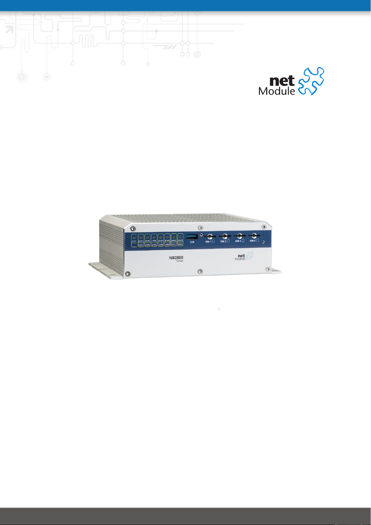
NetModule Router NB2800
User Manual for Software Version 4.2
Manual Version 1.12
NetModule AG, Switzerland
November 28, 2018
Page 2

NetModule Router NB2800
This manual covers all variants of the NB2800 product type.
The specifications and information regarding the products in this manual are subject to change without notice.
We would like to point out that NetModule makes no representation or warranties with respect to the contents
herein and shall not be responsible for any loss or damage caused to the user by the direct or indirect use of
this information This document may contain information about third party products or processes. Such third
party information is generally out of influence of NetModule and therefore NetModule shall not be responsible
for the correctness or legitimacy of this information. Users must take full responsibility for their application of
any products.
Copyright ©2018 NetModule AG, Switzerland All rights reserved
This document contains proprietary information of NetModule. No parts of the work described herein may be
reproduced. Reverse engineering of the hardware or software is prohibited and protected by patent law. This
material or any portion of it may not be copied in any form or by any means, stored in a retrieval system, adopted
or transmitted in any form or by any means (electronic, mechanical, photographic, graphic, optic or otherwise),
or translated in any language or computer language without the prior written permission of NetModule.
A large amount of the source code to this product is available under licenses which are both free and open
source. Most of it is covered by the GNU General Public License which can be obtained from www.gnu.org. The
remainder of the open source software which is not under the GPL, is usually available under one of a variety of
more permissive licenses. A detailed license information for a particular software package can be provided on
request.
All other products or company names mentioned herein are used for identification purposes only and may be
trademarks or registered trademarks of their respective owners. The following description of software, hardware or process of NetModule or other third party provider may be included with your product and will be
subject to the software, hardware or other license agreements.
Contact
www.netmodule.com/support
NetModule AG Tel +41 31 985 25 10
Meriedweg 11 Fax +41 31 985 25 11
CH-3172 Niederwangen [email protected]
Switzerland http://www.netmodule.com
Page 3

Contents
1. Welcome to NetModule . . . . . . . . . . . . . . . . . . . . . . . . . . . . . . . . . 1
2. Conformity . . . . . . . . . . . . . . . . . . . . . . . . . . . . . . . . . . . . . . . . 2
2.1. Safety Instructions . . . . . . . . . . . . . . . . . . . . . . . . . . . . . . . . . . 2
2.2. Declaration of Conformity . . . . . . . . . . . . . . . . . . . . . . . . . . . . . . 4
2.3. Waste Disposal . . . . . . . . . . . . . . . . . . . . . . . . . . . . . . . . . . . . 4
2.4. National Restrictions . . . . . . . . . . . . . . . . . . . . . . . . . . . . . . . . . 4
2.5. Open Source Software . . . . . . . . . . . . . . . . . . . . . . . . . . . . . . . . 5
3. Specifications . . . . . . . . . . . . . . . . . . . . . . . . . . . . . . . . . . . . . . . 6
3.1. Appearance . . . . . . . . . . . . . . . . . . . . . . . . . . . . . . . . . . . . . . 6
3.2. Features . . . . . . . . . . . . . . . . . . . . . . . . . . . . . . . . . . . . . . . . 7
3.3. Type Label . . . . . . . . . . . . . . . . . . . . . . . . . . . . . . . . . . . . . . . 7
3.4. Environmental Conditions . . . . . . . . . . . . . . . . . . . . . . . . . . . . . . 8
3.5. Interfaces . . . . . . . . . . . . . . . . . . . . . . . . . . . . . . . . . . . . . . . 9
3.5.1. Overview . . . . . . . . . . . . . . . . . . . . . . . . . . . . . . . . . . . . . 9
3.6. LED Indicators . . . . . . . . . . . . . . . . . . . . . . . . . . . . . . . . . . . . 10
3.6.1. Reset . . . . . . . . . . . . . . . . . . . . . . . . . . . . . . . . . . . . . . . 11
3.6.2. Mobile . . . . . . . . . . . . . . . . . . . . . . . . . . . . . . . . . . . . . . 13
3.6.3. WLAN . . . . . . . . . . . . . . . . . . . . . . . . . . . . . . . . . . . . . . . 14
3.6.4. GNSS . . . . . . . . . . . . . . . . . . . . . . . . . . . . . . . . . . . . . . . 15
3.6.5. USB 3.0 Host Port . . . . . . . . . . . . . . . . . . . . . . . . . . . . . . . . 16
3.6.6. RJ45 Ethernet Connectors . . . . . . . . . . . . . . . . . . . . . . . . . . . 16
3.6.7. 6 Pin Terminal Block . . . . . . . . . . . . . . . . . . . . . . . . . . . . . . 17
3.6.8. Extension Port . . . . . . . . . . . . . . . . . . . . . . . . . . . . . . . . . . 19
3.7. Data Storage (Option Dx) . . . . . . . . . . . . . . . . . . . . . . . . . . . . . . 24
4. Installation . . . . . . . . . . . . . . . . . . . . . . . . . . . . . . . . . . . . . . . . 27
4.1. Installation of Micro-SIM Cards . . . . . . . . . . . . . . . . . . . . . . . . . . . 27
4.2. Installation of the GSM/UMTS/LTE Antennas . . . . . . . . . . . . . . . . . . . 27
4.3. Installation of the WLAN Antennas . . . . . . . . . . . . . . . . . . . . . . . . . 28
4.4. Installation of the GNSS Antenna . . . . . . . . . . . . . . . . . . . . . . . . . . 29
4.5. Installation of the Local Area Network . . . . . . . . . . . . . . . . . . . . . . . 30
4.6. Installation of the Power Supply & Delayed Power Off . . . . . . . . . . . . . . 30
4.7. Installation of the Audio Interface . . . . . . . . . . . . . . . . . . . . . . . . . 30
5. Configuration . . . . . . . . . . . . . . . . . . . . . . . . . . . . . . . . . . . . . . . 31
5.1. First Steps . . . . . . . . . . . . . . . . . . . . . . . . . . . . . . . . . . . . . . . 31
5.1.1. Initial Access . . . . . . . . . . . . . . . . . . . . . . . . . . . . . . . . . . . 31
5.1.2. Recovery . . . . . . . . . . . . . . . . . . . . . . . . . . . . . . . . . . . . . 32
5.2. HOME . . . . . . . . . . . . . . . . . . . . . . . . . . . . . . . . . . . . . . . . . 34
5.3. INTERFACES . . . . . . . . . . . . . . . . . . . . . . . . . . . . . . . . . . . . . . 37
5.3.1. WAN . . . . . . . . . . . . . . . . . . . . . . . . . . . . . . . . . . . . . . . 37
5.3.2. Ethernet . . . . . . . . . . . . . . . . . . . . . . . . . . . . . . . . . . . . . 44
5.3.3. Mobile . . . . . . . . . . . . . . . . . . . . . . . . . . . . . . . . . . . . . . 50
5.3.4. WLAN . . . . . . . . . . . . . . . . . . . . . . . . . . . . . . . . . . . . . . . 55
5.3.5. Software Bridges . . . . . . . . . . . . . . . . . . . . . . . . . . . . . . . . 64
5.3.6. USB . . . . . . . . . . . . . . . . . . . . . . . . . . . . . . . . . . . . . . . . 65
5.3.7. Serial Port . . . . . . . . . . . . . . . . . . . . . . . . . . . . . . . . . . . . 68
3
Page 4

NB2800 User Manual 4.2
5.3.8. Audio . . . . . . . . . . . . . . . . . . . . . . . . . . . . . . . . . . . . . . . 72
5.3.9. GNSS . . . . . . . . . . . . . . . . . . . . . . . . . . . . . . . . . . . . . . . 73
5.4. ROUTING . . . . . . . . . . . . . . . . . . . . . . . . . . . . . . . . . . . . . . . 76
5.4.1. Static Routes . . . . . . . . . . . . . . . . . . . . . . . . . . . . . . . . . . . 76
5.4.2. Extended Routing . . . . . . . . . . . . . . . . . . . . . . . . . . . . . . . . 78
5.4.3. Multipath Routes . . . . . . . . . . . . . . . . . . . . . . . . . . . . . . . . 79
5.4.4. Mobile IP . . . . . . . . . . . . . . . . . . . . . . . . . . . . . . . . . . . . . 80
5.4.5. Quality Of Service . . . . . . . . . . . . . . . . . . . . . . . . . . . . . . . . 83
5.4.6. Multicast . . . . . . . . . . . . . . . . . . . . . . . . . . . . . . . . . . . . . 85
5.4.7. OSPF . . . . . . . . . . . . . . . . . . . . . . . . . . . . . . . . . . . . . . . 86
5.4.8. BGP . . . . . . . . . . . . . . . . . . . . . . . . . . . . . . . . . . . . . . . . 87
5.5. FIREWALL . . . . . . . . . . . . . . . . . . . . . . . . . . . . . . . . . . . . . . . 88
5.5.1. Administration . . . . . . . . . . . . . . . . . . . . . . . . . . . . . . . . . 88
5.5.2. Adress/Port Groups . . . . . . . . . . . . . . . . . . . . . . . . . . . . . . . 88
5.5.3. Rules . . . . . . . . . . . . . . . . . . . . . . . . . . . . . . . . . . . . . . . 89
5.5.4. NAPT . . . . . . . . . . . . . . . . . . . . . . . . . . . . . . . . . . . . . . . 91
5.6. VPN . . . . . . . . . . . . . . . . . . . . . . . . . . . . . . . . . . . . . . . . . . 94
5.6.1. OpenVPN . . . . . . . . . . . . . . . . . . . . . . . . . . . . . . . . . . . . 94
5.6.2. IPsec . . . . . . . . . . . . . . . . . . . . . . . . . . . . . . . . . . . . . . . 100
5.6.3. PPTP . . . . . . . . . . . . . . . . . . . . . . . . . . . . . . . . . . . . . . . 106
5.6.4. GRE . . . . . . . . . . . . . . . . . . . . . . . . . . . . . . . . . . . . . . . . 109
5.6.5. Dial-In . . . . . . . . . . . . . . . . . . . . . . . . . . . . . . . . . . . . . . 110
5.7. SERVICES . . . . . . . . . . . . . . . . . . . . . . . . . . . . . . . . . . . . . . . 112
5.7.1. SDK . . . . . . . . . . . . . . . . . . . . . . . . . . . . . . . . . . . . . . . . 112
5.7.2. DHCP Server . . . . . . . . . . . . . . . . . . . . . . . . . . . . . . . . . . . 121
5.7.3. DNS Server . . . . . . . . . . . . . . . . . . . . . . . . . . . . . . . . . . . . 123
5.7.4. NTP Server . . . . . . . . . . . . . . . . . . . . . . . . . . . . . . . . . . . . 125
5.7.5. Dynamic DNS . . . . . . . . . . . . . . . . . . . . . . . . . . . . . . . . . . 126
5.7.6. E-Mail . . . . . . . . . . . . . . . . . . . . . . . . . . . . . . . . . . . . . . . 128
5.7.7. Events . . . . . . . . . . . . . . . . . . . . . . . . . . . . . . . . . . . . . . 129
5.7.8. SMS . . . . . . . . . . . . . . . . . . . . . . . . . . . . . . . . . . . . . . . . 130
5.7.9. SSH/Telnet Server . . . . . . . . . . . . . . . . . . . . . . . . . . . . . . . . 132
5.7.10.SNMP Agent . . . . . . . . . . . . . . . . . . . . . . . . . . . . . . . . . . . 134
5.7.11.Web Server . . . . . . . . . . . . . . . . . . . . . . . . . . . . . . . . . . . 139
5.7.12.Discovery . . . . . . . . . . . . . . . . . . . . . . . . . . . . . . . . . . . . 140
5.7.13.Redundancy . . . . . . . . . . . . . . . . . . . . . . . . . . . . . . . . . . . 141
5.7.14.Voice Gateway . . . . . . . . . . . . . . . . . . . . . . . . . . . . . . . . . . 143
5.8. SYSTEM . . . . . . . . . . . . . . . . . . . . . . . . . . . . . . . . . . . . . . . . 149
5.8.1. System . . . . . . . . . . . . . . . . . . . . . . . . . . . . . . . . . . . . . . 149
5.8.2. Authentication . . . . . . . . . . . . . . . . . . . . . . . . . . . . . . . . . . 155
5.8.3. Software Update . . . . . . . . . . . . . . . . . . . . . . . . . . . . . . . . 158
5.8.4. Module Firmware Update . . . . . . . . . . . . . . . . . . . . . . . . . . . 159
5.8.5. Software Profiles . . . . . . . . . . . . . . . . . . . . . . . . . . . . . . . . 160
5.8.6. Configuration . . . . . . . . . . . . . . . . . . . . . . . . . . . . . . . . . . 161
5.8.7. Troubleshooting . . . . . . . . . . . . . . . . . . . . . . . . . . . . . . . . . 164
5.8.8. Keys and Certificates . . . . . . . . . . . . . . . . . . . . . . . . . . . . . . 167
5.8.9. Licensing . . . . . . . . . . . . . . . . . . . . . . . . . . . . . . . . . . . . . 172
4
Page 5

NB2800 User Manual 4.2
5.8.10.Legal Notice . . . . . . . . . . . . . . . . . . . . . . . . . . . . . . . . . . . 173
5.9. LOGOUT . . . . . . . . . . . . . . . . . . . . . . . . . . . . . . . . . . . . . . . . 174
6. Command Line Interface . . . . . . . . . . . . . . . . . . . . . . . . . . . . . . . . 175
6.1. General Usage . . . . . . . . . . . . . . . . . . . . . . . . . . . . . . . . . . . . 175
6.2. Print Help . . . . . . . . . . . . . . . . . . . . . . . . . . . . . . . . . . . . . . . 176
6.3. Getting Config Parameters . . . . . . . . . . . . . . . . . . . . . . . . . . . . . 177
6.4. Setting Config Parameters . . . . . . . . . . . . . . . . . . . . . . . . . . . . . . 177
6.5. Checking Config Completed . . . . . . . . . . . . . . . . . . . . . . . . . . . . . 177
6.6. Getting Status Information . . . . . . . . . . . . . . . . . . . . . . . . . . . . . 177
6.7. Scanning Networks . . . . . . . . . . . . . . . . . . . . . . . . . . . . . . . . . . 178
6.8. Sending E-Mail or SMS . . . . . . . . . . . . . . . . . . . . . . . . . . . . . . . . 178
6.9. Updating System Facilities . . . . . . . . . . . . . . . . . . . . . . . . . . . . . . 179
6.10. Manage keys and certificates . . . . . . . . . . . . . . . . . . . . . . . . . . . . 179
6.11. Restarting Services . . . . . . . . . . . . . . . . . . . . . . . . . . . . . . . . . . 180
6.12. Debug System . . . . . . . . . . . . . . . . . . . . . . . . . . . . . . . . . . . . . 180
6.13. Resetting System . . . . . . . . . . . . . . . . . . . . . . . . . . . . . . . . . . . 181
6.14. Rebooting System . . . . . . . . . . . . . . . . . . . . . . . . . . . . . . . . . . 181
6.15. Running Shell Commands . . . . . . . . . . . . . . . . . . . . . . . . . . . . . . 181
6.16. Working with History . . . . . . . . . . . . . . . . . . . . . . . . . . . . . . . . . 182
6.17. CLI-PHP . . . . . . . . . . . . . . . . . . . . . . . . . . . . . . . . . . . . . . . . 182
A. Appendix . . . . . . . . . . . . . . . . . . . . . . . . . . . . . . . . . . . . . . . . . 187
A.1. Abbrevations . . . . . . . . . . . . . . . . . . . . . . . . . . . . . . . . . . . . . 187
A.2. System Events . . . . . . . . . . . . . . . . . . . . . . . . . . . . . . . . . . . . 189
A.3. Factory Configuration . . . . . . . . . . . . . . . . . . . . . . . . . . . . . . . . 191
A.4. SNMP VENDOR MIB . . . . . . . . . . . . . . . . . . . . . . . . . . . . . . . . . 192
A.5. SDK Examples . . . . . . . . . . . . . . . . . . . . . . . . . . . . . . . . . . . . . 211
5
Page 6

List of Figures
5.1. Initial Login . . . . . . . . . . . . . . . . . . . . . . . . . . . . . . . . . . . . . . 32
5.2. Home . . . . . . . . . . . . . . . . . . . . . . . . . . . . . . . . . . . . . . . . . 34
5.3. WAN Links . . . . . . . . . . . . . . . . . . . . . . . . . . . . . . . . . . . . . . 37
5.4. WAN Settings . . . . . . . . . . . . . . . . . . . . . . . . . . . . . . . . . . . . . 41
5.5. Link Supervision . . . . . . . . . . . . . . . . . . . . . . . . . . . . . . . . . . . 42
5.6. Ethernet Ports . . . . . . . . . . . . . . . . . . . . . . . . . . . . . . . . . . . . 44
5.7. Ethernet Link Settings . . . . . . . . . . . . . . . . . . . . . . . . . . . . . . . . 45
5.8. VLAN Management . . . . . . . . . . . . . . . . . . . . . . . . . . . . . . . . . . 46
5.9. LAN IP Configuration . . . . . . . . . . . . . . . . . . . . . . . . . . . . . . . . 48
5.10. SIMs . . . . . . . . . . . . . . . . . . . . . . . . . . . . . . . . . . . . . . . . . . 50
5.11. WWAN Interfaces . . . . . . . . . . . . . . . . . . . . . . . . . . . . . . . . . . 53
5.12. WLAN Management . . . . . . . . . . . . . . . . . . . . . . . . . . . . . . . . . 55
5.13. WLAN Configuration . . . . . . . . . . . . . . . . . . . . . . . . . . . . . . . . . 59
5.14. WLAN IP Configuration . . . . . . . . . . . . . . . . . . . . . . . . . . . . . . . 63
5.15. USB Administration . . . . . . . . . . . . . . . . . . . . . . . . . . . . . . . . . 65
5.16. USB Device Management . . . . . . . . . . . . . . . . . . . . . . . . . . . . . . 66
5.17. Serial Port Administration . . . . . . . . . . . . . . . . . . . . . . . . . . . . . . 68
5.18. Serial Port Settings . . . . . . . . . . . . . . . . . . . . . . . . . . . . . . . . . . 69
5.19. Static Routing . . . . . . . . . . . . . . . . . . . . . . . . . . . . . . . . . . . . . 76
5.20. Extended Routing . . . . . . . . . . . . . . . . . . . . . . . . . . . . . . . . . . 78
5.21. Multipath Routes . . . . . . . . . . . . . . . . . . . . . . . . . . . . . . . . . . . 79
5.22. Mobile IP . . . . . . . . . . . . . . . . . . . . . . . . . . . . . . . . . . . . . . . 82
5.23. Firewall Groups . . . . . . . . . . . . . . . . . . . . . . . . . . . . . . . . . . . . 88
5.24. Firewall Rules . . . . . . . . . . . . . . . . . . . . . . . . . . . . . . . . . . . . . 89
5.25. Masquerading . . . . . . . . . . . . . . . . . . . . . . . . . . . . . . . . . . . . 91
5.26. Inbound NAPT . . . . . . . . . . . . . . . . . . . . . . . . . . . . . . . . . . . . 92
5.27. OpenVPN Administration . . . . . . . . . . . . . . . . . . . . . . . . . . . . . . 94
5.28. OpenVPN Configuration . . . . . . . . . . . . . . . . . . . . . . . . . . . . . . . 95
5.29. OpenVPN Client Management . . . . . . . . . . . . . . . . . . . . . . . . . . . 99
5.30. IPsec Administration . . . . . . . . . . . . . . . . . . . . . . . . . . . . . . . . . 101
5.31. IPsec Configuration . . . . . . . . . . . . . . . . . . . . . . . . . . . . . . . . . 102
5.32. PPTP Administration . . . . . . . . . . . . . . . . . . . . . . . . . . . . . . . . . 106
5.33. PPTP Tunnel Configuration . . . . . . . . . . . . . . . . . . . . . . . . . . . . . 107
5.34. PPTP Client Management . . . . . . . . . . . . . . . . . . . . . . . . . . . . . . 108
5.35. Dial-in Server Settings . . . . . . . . . . . . . . . . . . . . . . . . . . . . . . . . 110
5.36. SDK Administration . . . . . . . . . . . . . . . . . . . . . . . . . . . . . . . . . 116
5.37. SDK Jobs . . . . . . . . . . . . . . . . . . . . . . . . . . . . . . . . . . . . . . . . 117
5.38. DHCP Server . . . . . . . . . . . . . . . . . . . . . . . . . . . . . . . . . . . . . 121
5.39. DNS Server . . . . . . . . . . . . . . . . . . . . . . . . . . . . . . . . . . . . . . 123
5.40. NTP Server . . . . . . . . . . . . . . . . . . . . . . . . . . . . . . . . . . . . . . 125
5.41. Dynamic DNS Settings . . . . . . . . . . . . . . . . . . . . . . . . . . . . . . . . 126
5.42. E-Mail Settings . . . . . . . . . . . . . . . . . . . . . . . . . . . . . . . . . . . . 128
5.43. SMS Configuration . . . . . . . . . . . . . . . . . . . . . . . . . . . . . . . . . . 130
5.44. SSH and Telnet Server . . . . . . . . . . . . . . . . . . . . . . . . . . . . . . . . 132
6
Page 7

NB2800 User Manual 4.2
5.45. SNMP Agent . . . . . . . . . . . . . . . . . . . . . . . . . . . . . . . . . . . . . 135
5.46. Web Server . . . . . . . . . . . . . . . . . . . . . . . . . . . . . . . . . . . . . . 139
5.47. VRRP Configuration . . . . . . . . . . . . . . . . . . . . . . . . . . . . . . . . . 141
5.48. Voice Gateway Administration . . . . . . . . . . . . . . . . . . . . . . . . . . . 143
5.49. System . . . . . . . . . . . . . . . . . . . . . . . . . . . . . . . . . . . . . . . . 149
5.50. Regional settings . . . . . . . . . . . . . . . . . . . . . . . . . . . . . . . . . . . 152
5.51. User Accounts . . . . . . . . . . . . . . . . . . . . . . . . . . . . . . . . . . . . 155
5.52. Remote Authentication . . . . . . . . . . . . . . . . . . . . . . . . . . . . . . . 156
5.53. Manual File Configuration . . . . . . . . . . . . . . . . . . . . . . . . . . . . . . 161
5.54. Automatic File Configuration . . . . . . . . . . . . . . . . . . . . . . . . . . . . 162
5.55. Factory Configuration . . . . . . . . . . . . . . . . . . . . . . . . . . . . . . . . 163
5.56. Log Viewer . . . . . . . . . . . . . . . . . . . . . . . . . . . . . . . . . . . . . . 165
5.57. Tech Support File . . . . . . . . . . . . . . . . . . . . . . . . . . . . . . . . . . . 166
5.58. Keys and certificates . . . . . . . . . . . . . . . . . . . . . . . . . . . . . . . . . 167
5.59. Certificate Configuration . . . . . . . . . . . . . . . . . . . . . . . . . . . . . . 169
5.60. Licensing . . . . . . . . . . . . . . . . . . . . . . . . . . . . . . . . . . . . . . . 172
7
Page 8

List of Tables
3.1. Environmental Conditions . . . . . . . . . . . . . . . . . . . . . . . . . . . . . . 8
3.2. NB2800 Interfaces . . . . . . . . . . . . . . . . . . . . . . . . . . . . . . . . . . 10
3.3. NB2800 Status Indicators . . . . . . . . . . . . . . . . . . . . . . . . . . . . . . 11
3.4. Ethernet Status Indicators . . . . . . . . . . . . . . . . . . . . . . . . . . . . . 11
3.5. Mobile Interface . . . . . . . . . . . . . . . . . . . . . . . . . . . . . . . . . . . 13
3.6. Mobile Antenna Port Specification . . . . . . . . . . . . . . . . . . . . . . . . . 13
3.7. IEEE 802.11 Standards . . . . . . . . . . . . . . . . . . . . . . . . . . . . . . . . 14
3.8. WLAN Antenna Port Specification . . . . . . . . . . . . . . . . . . . . . . . . . 14
3.9. GNSS Specifications option G . . . . . . . . . . . . . . . . . . . . . . . . . . . . 15
3.10. GNSS Specifications option Ge . . . . . . . . . . . . . . . . . . . . . . . . . . . 15
3.11. GNSS / GPS Antenna Port Specification . . . . . . . . . . . . . . . . . . . . . . 15
3.12. USB 3.0 Host Port Specification . . . . . . . . . . . . . . . . . . . . . . . . . . . 16
3.13. Ethernet Port Specification . . . . . . . . . . . . . . . . . . . . . . . . . . . . . 16
3.14. Pin Assignments of RJ45 Ethernet Connectors . . . . . . . . . . . . . . . . . . 17
3.15. 6 Pin Terminal Block Specifications . . . . . . . . . . . . . . . . . . . . . . . . . 17
3.16. Pin Assignments of Terminal Block . . . . . . . . . . . . . . . . . . . . . . . . . 17
3.17. Power Specifications . . . . . . . . . . . . . . . . . . . . . . . . . . . . . . . . . 18
3.18. RS-232 Port Specification . . . . . . . . . . . . . . . . . . . . . . . . . . . . . . 18
3.19. Audio Port Specification . . . . . . . . . . . . . . . . . . . . . . . . . . . . . . . 20
3.20. Pin Assignments of RJ45 Audio Connector . . . . . . . . . . . . . . . . . . . . . 20
3.21. CAN Port Specification . . . . . . . . . . . . . . . . . . . . . . . . . . . . . . . . 21
3.22. Pin Assignments of RJ45 CAN Connector . . . . . . . . . . . . . . . . . . . . . 21
3.23. Isolated RS-232 Port Specification . . . . . . . . . . . . . . . . . . . . . . . . . 22
3.24. Pin Assignments of RJ45 RS-232 Connector . . . . . . . . . . . . . . . . . . . . 22
3.25. RS-485 Port Specification . . . . . . . . . . . . . . . . . . . . . . . . . . . . . . 23
3.26. Pin Assignments of RJ45 RS-485 Connector . . . . . . . . . . . . . . . . . . . . 23
3.27. Storage Specifications . . . . . . . . . . . . . . . . . . . . . . . . . . . . . . . . 24
3.28. Common PTT Specification . . . . . . . . . . . . . . . . . . . . . . . . . . . . . 25
3.29. Audio Port Specification . . . . . . . . . . . . . . . . . . . . . . . . . . . . . . . 25
3.30. Digital Input Specification . . . . . . . . . . . . . . . . . . . . . . . . . . . . . . 25
3.31. Digital Output Specification . . . . . . . . . . . . . . . . . . . . . . . . . . . . . 26
3.32. Pin Assignments of RJ45 Audio-PTT Connector . . . . . . . . . . . . . . . . . . 26
4.1. LTE/UMTS antenna port types . . . . . . . . . . . . . . . . . . . . . . . . . . . 28
4.2. WLAN antenna port types . . . . . . . . . . . . . . . . . . . . . . . . . . . . . . 29
5.20. IEEE 802.11 Network Standards . . . . . . . . . . . . . . . . . . . . . . . . . . 56
5.44. Static Route Flags . . . . . . . . . . . . . . . . . . . . . . . . . . . . . . . . . . 77
5.90. SMS Control Commands . . . . . . . . . . . . . . . . . . . . . . . . . . . . . . 120
5.100. SMS Number Expressions . . . . . . . . . . . . . . . . . . . . . . . . . . . . . . 131
5.142. Certificate Sections . . . . . . . . . . . . . . . . . . . . . . . . . . . . . . . . . . 168
5.143. Certificate Operations . . . . . . . . . . . . . . . . . . . . . . . . . . . . . . . . 168
A.1. Abbreviations . . . . . . . . . . . . . . . . . . . . . . . . . . . . . . . . . . . . . 188
A.2. System Events . . . . . . . . . . . . . . . . . . . . . . . . . . . . . . . . . . . . 190
8
Page 9

NB2800 User Manual 4.2
A.3. SDK Examples . . . . . . . . . . . . . . . . . . . . . . . . . . . . . . . . . . . . 213
9
Page 10

1. Welcome to NetModule
Thank you for purchasing a NetModule Router. This document should give you an introduction to the router and its features. The following chapters describe any aspects of commissioning the device, installation procedure and provide helpful information towards configuration and maintenance.
Please find further imformation such as sample SDK script or configuration samples in our
wiki on http://wiki.netmodule.com.
1
Page 11
2. Conformity
This chapter provides general information for putting the router into operation.
2.1. Safety Instructions
Please carefully observe all safety instructions in the manual that are marked with the sym-
bol .
Compliance information: The NetModule routers must be used in compliance with any and all applicable national and international laws and with any
special restrictions regulating the utilization of the communication module in
prescribed applications and environments.
Information about the accessories / changes to the device:
• Please only use original accessories to prevent injuries and health risks.
• Changes made to the device or the use of non-authorized accessories will
render the warranty null and void and potentially invalidate the operating
license.
• NetModule routers must not be opened (SIM cards may be used according
to the instructions).
2
Page 12
NB2800 User Manual 4.2
Information about the device interfaces:
• All systems that are connected to the NetModule router interfaces must meet
the requirements for SELV (Safety Extra Low Voltage) systems.
• Interconnections must not leave the building nor penetrate the body shell of
a vehicle.
• Connections for antennas may only exit the building or the vehicle hull if
transient overvoltages (according to IEC 62368-1) are limited by external protection circuits down to 1 500 Vpeak. All other connections must remain within
the building or the vehicle hull.
• Always keep a distance of more than 40 cm from the antenna in order to
reduce exposure to electromagnetic fields below the legal limits.
• Devices with a WLAN interface may be operated only with applicable Regulatory Domain configured. Special attention must be paid to country, number
of antennas and the antenna gain (see also chapter 5.3.4). The maximum
allowed gain is 3dBi in the relevant frequency range. WLAN antennas with a
higher amplification may be used with the NetModule router "Enhanced-RFConfiguration" software license and the antenna gain and cable attenuation
that have been correctly configured by certified specialized personnel. A misconfiguration will lead to loss of the approval.
• Cellular antennas attached to the router must have an antenna gain of equal
or less than 2.5 dBi. The user is responsible for the compliance with the legal
regulations.
• Only CE-compliant power supplies with a current-limited SELV output voltage
range may be used with the NetModule routers.
3
Page 13

NB2800 User Manual 4.2
General safety instructions:
• Observe the usage limitations of radio units at filling stations, in chemical
plants, in systems with explosives or potentially explosive locations.
• The devices may not be used in airplanes.
• Exercise particular caution near personal medical aids, such as pacemakers
and hearing aids.
• The NetModule routers may also cause interference in the nearer distance of
TV sets, radio receivers and personal computers.
• Never perform work on the antenna system during a thunderstorm.
• The devices are generally designed for normal indoor use. Do not expose the
devices to extraordinary environmental conditions worse than IP40.
• Protect them against aggressive chemical atmospheres and humidity or temperatures outside specifications.
• We highly recommended creating a copy of a working system configuration.
It can be easily applied to a newer software release afterwards.
2.2. Declaration of Conformity
NetModule hereby declares that under our own responsibility that the
routers comply with the relevant standards following the provisions of the
RED Directive 2014/53/EU. The signed version of the Declaration of Conformity can be obtained from http://www.netmodule.com/downloads
2.3. Waste Disposal
In accordance with the requirements of the Council Directive 2012/19/EU
regarding Waste Electrical and Electronic Equipment (WEEE), you are
urged to ensure that this product will be segregated from other waste
at end-of-life and delivered to the WEEE collection system in your country
for proper recycling.
2.4. National Restrictions
This product may be generally used in all EU countries (and other countries following the
RED Directive 2014/53/EU) without any limitation. Please refer to our WLAN Regulatory
Database for getting further national radio interface regulations and requirements for a
particular country.
4
Page 14

NB2800 User Manual 4.2
2.5. Open Source Software
We inform you that NetModule products may contain in part open-source software. We
are distributing such open-source software to you under the terms of GNU General Public
License (GPL)1, GNU Lesser General Public License (LGPL)2or other open-source licenses3.
These licenses allow you to run, copy, distribute, study, change and improve any software
covered by GPL, Lesser GPL, or other open-source licenses without any restrictions from us
or our end user license agreement on what you may do with that software. Unless required
by applicable law or agreed to in writing, software distributed under open-source licenses
is distributed on an "AS IS" basis, WITHOUT WARRANTIES OR CONDITIONS OF ANY KIND,
either express or implied.
To obtain the corresponding open source codes covered by these licenses, please contact
our technical support at [email protected].
Acknowledgements
This product includes:
• PHP, freely available from http://www.php.net
• Software developed by the OpenSSL Project for use in the OpenSSL Toolkit (http://www.openssl.org)
• Cryptographic software written by Eric Young ([email protected])
• Software written by Tim Hudson ([email protected])
• Software written Jean-loup Gailly and Mark Adler
• MD5 Message-Digest Algorithm by RSA Data Security, Inc.
• An implementation of the AES encryption algorithm based on code released by Dr
Brian Gladman
• Multiple-precision arithmetic code originally written by David Ireland
• Software from The FreeBSD Project (http://www.freebsd.org)
1
Please find the GPL text under http://www.gnu.org/licenses/gpl-2.0.txt
2
Please find the LGPL text under http://www.gnu.org/licenses/lgpl.txt
3
Please find the license texts of OSI licenses (ISC License, MIT License, PHP License v3.0, zlib License) under
http://opensource.org/licenses
5
Page 15
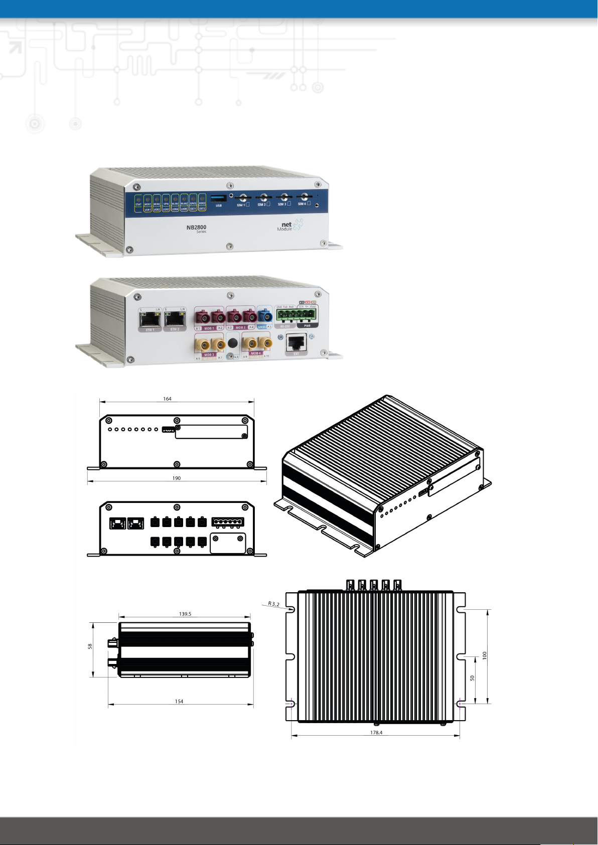
3. Specifications
3.1. Appearance
6
Page 16

NB2800 User Manual 4.2
3.2. Features
All models of NB2800 have following standard functionalities:
• Power input with Ingition Sense
• 2 Ethernet ports (10/100/1000 Mbit/s)
• 1 serial port (RS-232)
• 1 USB 3.0 host port
• 4 micro SIM card slots
• Extension port
The NB2800 can be equipped with the following options:
• LTE
• LTE 450MHz
• LTE US
• CDMA 450MHz
• WLAN IEEE 802.11ac
• GPS/GNSS
• RS-232
• RS-485
• IBIS
• CAN
• Audio
• Audio-PTT
• 1 TB internal storage
• Software Key Virtualization
• Software Key Server
• Software Key Voice
Note: All LTE models include support for UMTS/EDGE/GPRS.
Due to its modular approach, the NB2800 router and its hardware components can be
arbitrarily assembled according to its indented usage or application. Please contact us in
case of special project requirements.
3.3. Type Label
The type label of the NB2800 router is located on the bottom side of the enclosure.
7
Page 17

NB2800 User Manual 4.2
3.4. Environmental Conditions
Parameter Rating
Input Voltage 12 VDC to 48 VDC (±25%)
main board: −40◦C to +85◦C
Operating Temperature Range
Storage Temperature Range −40◦C to +85◦C
Humidity 0 to 95% (non-condensing)
Altitude up to 4000m
Over-Voltage Category I
Pollution Degree 2
Ingress Protection Rating IP40 (with SIM and USB covers mounted)
Table 3.1.: Environmental Conditions
UMTS: −25◦C to +70◦C
LTE: −25◦C to +70◦C
WLAN: −25◦C to +70◦C
8
Page 18
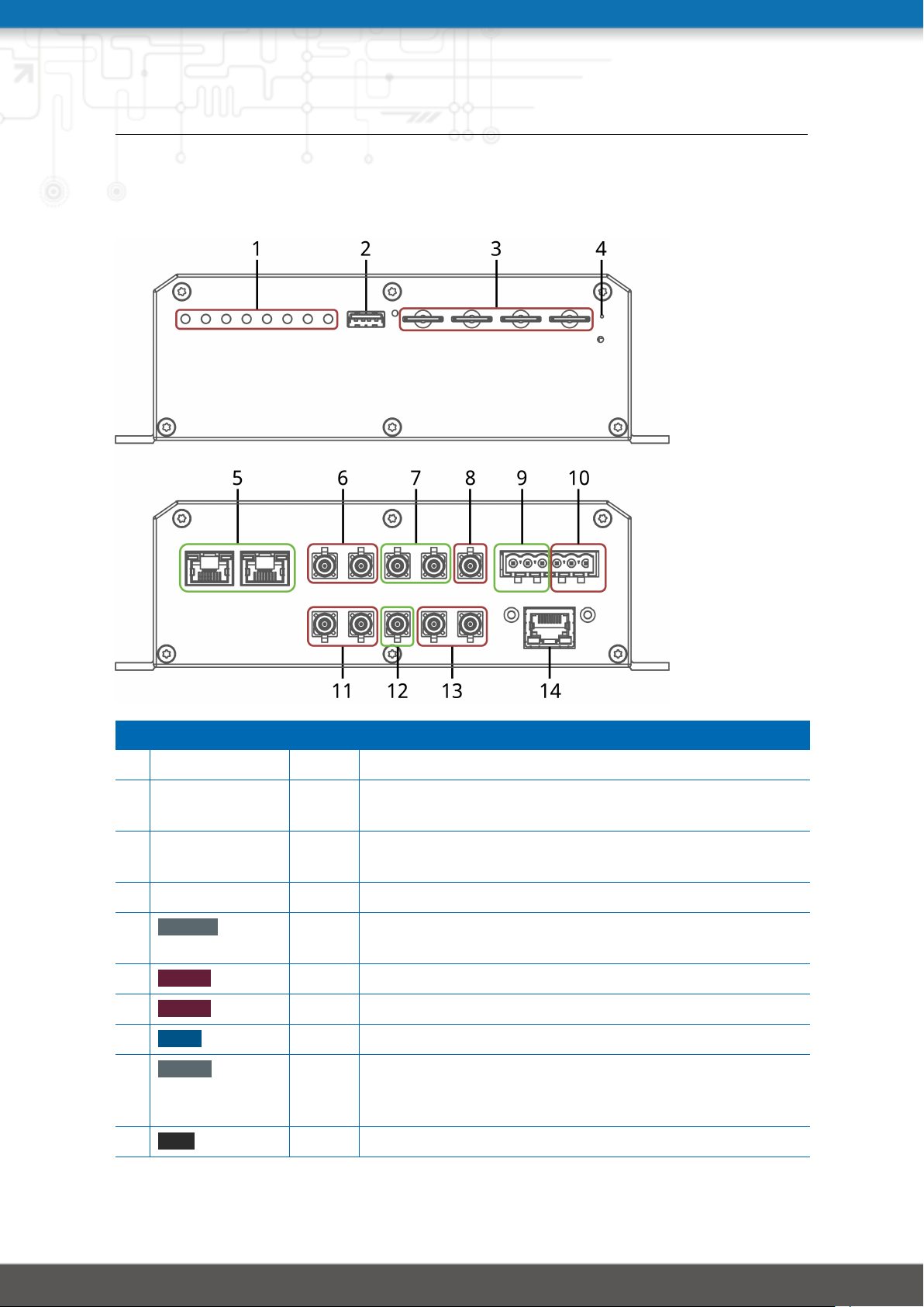
3.5. Interfaces
3.5.1. Overview
NB2800 User Manual 4.2
Nr. Label Panel Function
1 LED Indicators Front LED Indicators for the different interfaces
2 USB Front USB 2.0 host port, can be used for software/configuration
updates.
3 SIM 1-4 Front SIM 1-4, they can be assigned dynamically to any modem
by configuration.
4 Reset Front Reboot and factory reset button
5 ETH 1-2 Rear Gigabit Ethernet ports, can be used as LAN or WAN inter-
face.
6 MOB 1 Rear 2 FAKRA coding D jacks for MIMO LTE antenna
7 MOB 2 Rear 2 FAKRA coding D jacks for MIMO LTE antenna
8 GNSS Rear FAKRA coding C jack for GNSS antenna
9 RS-232 Rear Non-isolated serial RS-232 interface (Pins 4 to 6) which
can be used for console administration, serial device
server or other serial based communication applications.
10 PWR Rear Power supply 12-48 VDC (Pins 1 and 2) and Ignition (Pin 3)
9
Page 19

NB2800 User Manual 4.2
Nr. Label Panel Function
11 MOB 3/
WLAN 2
Rear 2 FAKRA coding I/D jacks for MIMO WLAN 2 or MIMO LTE
antenna
12 A8 Rear Auxiliary port
13 MOB 4/
WLAN 1
Rear 2 FAKRA coding I/D jacks for MIMO WLAN or MIMO LTE
antenna
14 EXT Rear Audio/CAN/IBIS/RS-232/RS-485/Audio-PTT extension.
Table 3.2.: NB2800 Interfaces
3.6. LED Indicators
The following table describes the NB2800 status indicators.
Label Color State Function
STAT l blinking The device is busy due to startup, software or configura-
tion update.
l on The device is ready. The captions of the top bank apply.
l on The device is ready. The captions of the bottom bank ap-
ply.
MOB1 lll
[1]
on Mobile connection 1 is up.
l blinking Mobile connection 1 is being established.
m off Mobile connection 1 is down.
MOB2 lll
[1]
on Mobile connection 2 is up.
l blinking Mobile connection 2 is being established.
m off Mobile connection 2 is down.
VPN l on VPN connection is up.
m off VPN connection is down.
WLAN1 lll
[1]
on WLAN 1 connection is up.
l blinking WLAN 1 connection is being established.
m off WLAN 1 connection is down.
WLAN2 lll
[1]
on WLAN 2 connection is up.
l blinking WLAN 2 connection is being established.
m off WLAN 2 connection is down.
10
Page 20

NB2800 User Manual 4.2
Label Color State Function
GNSS l on GNSS is turned on and a valid NMEA stream is available.
l blinking GNSS is searching for satellites.
m off GNSS is turned off or no valid NMEA stream is available.
VOICE l on A voice call is currently active.
m off No voice call is active.
USR1-
l on User defined.
5
m off User defined.
EXT1 l on Extension port 1 is on.
m off Extension port 1 is off.
EXT2 l on Extension port 2 is on.
m off Extension port 2 is off.
[1]
The color of the LED represents the signal quality for wireless links.
l red means low
l yellow means moderate
l green means good or excellent
Table 3.3.: NB2800 Status Indicators
Ethernet LEDs
The following table describes the Ethernet status indicators.
Label Color State Function
ETH1-2 l on Link on (10 Mbit/s, 100 Mbit/s or 1000 Mbit/s)
l blinking Activity
m off no Link
Table 3.4.: Ethernet Status Indicators
3.6.1. Reset
The reset button has two functions:
1. Reboot the system:
Press at least 3 seconds to release a system reboot.
The reboot is indicated with the red blinking STAT LED.
2. Factory reset:
Press at least 10 seconds to release a factory reset.
11
Page 21

NB2800 User Manual 4.2
The start of the factory reset is confirmed by all LEDs lighting up for a second.
12
Page 22

NB2800 User Manual 4.2
3.6.2. Mobile
The various variants of the NB2800support multiple multimode modules for mobile communication.
Standard Bands Data rate
4G (LTE/FDD) B1(2100), B2(1900), B3(1800), B5(850),
B7(2600), B8(900), B20(800)
3G (DC-HSPA+/UMTS) B5(850), B8(900), B2(1900), B1(2100) Downlink: 42 Mbit/s
2G (EDGE/GPRS/GSM) B9(900), B3(1800), B2(1900) Downlink: 236.8 kbit/s
LTE450 LTE Band 3 (1800 MHz), LTE Band 7
(2600 MHz), LTE Band 20 (800 MHz),
LTE Band 31 (450 MHz), UMTS Band 1
(2100 MHz), UMTS Band 8 (900 MHz)
CDMA450 Band Class 5 Block Designators A + B Downlink: 14.7 Mbit/s
LTE Advanced Cat. 6 B30 (2300 WCS), B41 (TDD 2500), B29
(US 700de Lower), B26 (US 850 Ext), B25
(1900), B5 (850), B20 (800DD), B13 (700c),
B12 (700ac), B7 (2600), B4 (AWS), B3
(1800), B2 (1900), B1 (2100)
Table 3.5.: Mobile Interface
Downlink: 100 Mbit/s
Uplink: 50 Mbit/s
Uplink: 5.76 Mbit/s
Uplink: 236.8 kbit/s
Downlink: 100 Mbit/s
Uplink: 50 Mbit/s
Uplink: 5.4 Mbit/s
Downlink: 300 Mbit/s
Uplink: 50 Mbit/s
Note: This enumeration is not meant to be exhaustive.
The LTE modules support 2x2 MIMO.
The mobile antenna ports have the following specification:
Feature Specification
Max. allowed cable length 30 m
Max. allowed antenna gain
including cable attenuation
Min. distance between collocated
radio transmitter antennas
Min. distance between people and
antenna
Connector type Option Jf: FAKRA (Standard)
Table 3.6.: Mobile Antenna Port Specification
2.5 dBi
20 cm
40 cm
Option Js: SMA
13
Page 23

NB2800 User Manual 4.2
3.6.3. WLAN
The variants of the NB2800 support up to 2 802.11 a/b/g/n/ac WLAN modules. Each can
operate either as client or access point.
Standard Frequencies Bandwidth Data Rate
802.11a 5 GHz 20 MHz 54 Mbit/s
802.11b 2.4 GHz 20 MHz 11 Mbit/s
802.11g 2.4 GHz 20 MHz 54 Mbit/s
802.11n 2.4/5 GHz 20/40 MHz 300 Mbit/s
802.11ac 5 GHz 20/40/80 MHz 866.7 Mbit/s
Table 3.7.: IEEE 802.11 Standards
Note: 802.11n and 802.11ac support 2x2 MIMO
The WLAN antenna ports have the following specification:
Feature Specification
Max. allowed cable length 30 m
Max. allowed antenna gain
3.0 dBi
1
including cable attenuation
Min. distance between collocated
20 cm
radio transmitter antennas
(Example: WLAN1 to MOB1)
Min. distance between people and
40 cm
antenna
Connector type Option Jf: FAKRA (Standard)
Option Js: SMA
Table 3.8.: WLAN Antenna Port Specification
1
Note: WLAN antennas with a higher amplification may be used with the NetModule router "Enhanced-RF-
Configuration" software license and the antenna gain and cable attenuation that have been correctly configured by certified specialized personnel.
14
Page 24

NB2800 User Manual 4.2
3.6.4. GNSS
GNSS (Option G)
The GNSS is used from a WWAN Module.
Feature Specification
Systems GPS/GLONASS
Data stream JSON or NMEA
Tracking sensitivity -154 dBm
Supported antennas Active and passive
Table 3.9.: GNSS Specifications option G
GNSS (Option Ge)
The GNSS module supports Dead Reckoning with onboard 3D accelerometer and 3D gyroscope.
Feature Specification
Systems GPS/GLONASS/BeiDu/Galileo ready
Data stream NMEA or UBX
Tracking sensitivity -160 dBm
Channels 72
Accuracy 2m
Supported antennas Active and passive
Table 3.10.: GNSS Specifications option Ge
The GNSS antenna port have the following specification:
Feature Specification
Max. allowed cable length 30 m
Max. allowed antenna gain 3.0 dBi
Min. distance between collocated
radio transmitter antennas
(Example: WLAN1 to MOB1)
20 cm
Connector type Option Jf: FAKRA (Standard)
Option Js: SMA
Table 3.11.: GNSS / GPS Antenna Port Specification
15
Page 25
NB2800 User Manual 4.2
3.6.5. USB 3.0 Host Port
The USB 3.0 host port has the following specification:
Feature Specification
Speed Low, Full, Hi & Super-Speed
Current max. 950 mA
Max. cable length 3 m
Cable shield mandatory
Connector type Type A
Table 3.12.: USB 3.0 Host Port Specification
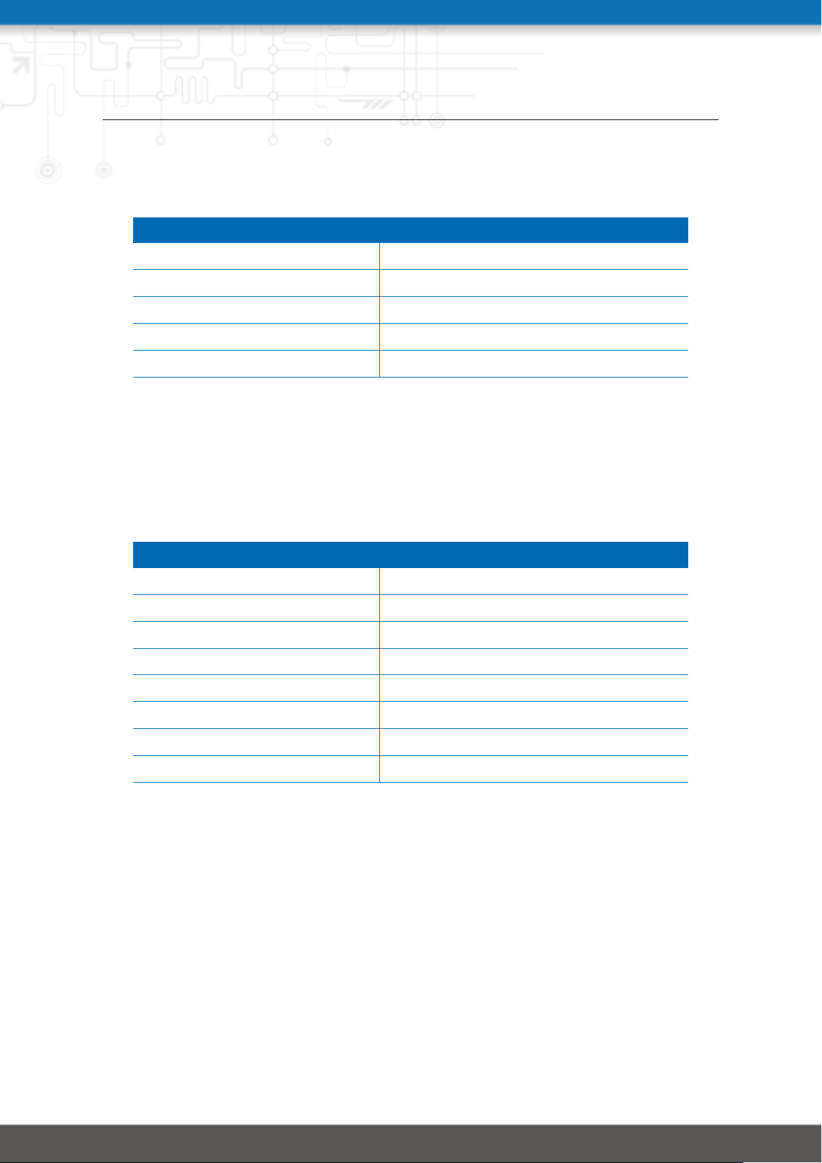
3.6.6. RJ45 Ethernet Connectors
Specification
The Ethernet ports have following specification:
Feature Specification
Isolation to enclosure 1500 VDC
Speed 10/100/1000 Mbit/s
Mode Half- & Full-Duplex
Crossover Automatic MDI/MDI-X
Max. cable length 100 m
Cable type CAT5e or better
Cable shield mandatory
Connector type RJ45
Table 3.13.: Ethernet Port Specification
16
Page 26

Pin Assignment
Pin Signal
1 M0+
2 M0−
3 M1+
4 M2+
5 M2−
6 M1−
7 M3+
8 M3−
Table 3.14.: Pin Assignments of RJ45 Ethernet Connectors
3.6.7. 6 Pin Terminal Block
NB2800 User Manual 4.2
Connector
The power supply and the serial interface shares the 6 pin terminal block.
Feature Specification
Connector pitch 5.00 mm
Connector in router Phoenix Contact MSTBA 2,5/6-G
Mating part on cable Phoenix Contact MSTB 2,5/6-ST
Table 3.15.: 6 Pin Terminal Block Specifications
Pin Assignment
Pin Name Description
1 VGND Power Ground
2 V+ Power Input (12 VDC to 48 VDC)
PWR
3 IGN Ignition Input (12 VDC to 48 VDC)
4 RxD RS-232 RxD (non-isolated)
5 TxD RS-232 TxD (non-isolated)
RS232
6 GND RS-232 GND (non-isolated)
Table 3.16.: Pin Assignments of Terminal Block
17
Page 27

NB2800 User Manual 4.2
Power Supply
NB2800 routers provide a non-isolated power supply input. The power port has the following specifications:
Feature Specification
Power supply nominal voltages 12 VDC, 24 VDC, 36 VDC and 48 VDC
Voltage range 12 VDC to 48 VDC (±25%)
Max. power consumption 20 W
12V: max. 0.23 mA / 2.8 mW
Off-state power consumption (V+)
Max. cable length 30 m
Cable shield not required
Table 3.17.: Power Specifications
RS-232
The RS-232 port is specified as follows (bold characters show the default configuration):
Feature Specification
Protocol 3-wire RS-232: GND, TXD, RXD
Baud rate 300, 1 200, 2 400, 4 800, 9 600, 19200,
Data bits 7 bit, 8 bit
Parity none, odd, even
24V: max. 0.34 mA / 8.1 mW
36V: max. 0.44 mA / 15.6 mW
48V: max. 0.56 mA / 27.1 mW
38 400, 57 600, 115 200, 230 400, 460 800
Stop bits 1, 2
Software flow control none, XON/XOFF
Hardware flow control none
Galvanic isolation to enclosure none
Max. cable length 10 m
Cable shield not required
Table 3.18.: RS-232 Port Specification
18
Page 28

NB2800 User Manual 4.2
3.6.8. Extension Port
Available Options
The NB2800 has an optional RJ45 extension connector with 8 pins. On this connector one of
the following interfaces may be present:
• Audio (Option A)
• CAN (Option C)
• IBIS (Option I)
• Isolated RS-485 (Option Sa)
• Isolated RS-232 (Option Sb)
• Audio PTT (Option Ap)
19
Page 29

NB2800 User Manual 4.2
Audio Port Specification (Option A)
The Audio port has the following specification:
Feature Specification
Protocol Audio Line In/Out
Input reference level 0dBFS Signal level 1.9 Vpp
Input Impedance 21 kΩ
Input bandwidth 100 Hz- 15 kHz
Input galvanic isolation to enclosure
Output voltage @ 0dBFS 600 Ω, signal level 3.7 Vpp
Output bandwidth 300 Hz- 4 kHz
Output galvanic isolation to enclosure
Max. cable length 30 m
Cable shield mandatory
Connector type RJ45
Table 3.19.: Audio Port Specification
Pin Signal
1 Input Left Channel +
2 Input Left Channel −
3 Input Right Channel +
4 Output Right Channel +
functional (max. 100 VDC)
functional (max. 100 VDC)
5 Common Output Right Channel −
6 Input Right Channel −
7 Output Left Channel +
8 Common Output Left Channel −
Table 3.20.: Pin Assignments of RJ45 Audio Connector
Note: In the case of mono operation the left channels are used.
20
Page 30

NB2800 User Manual 4.2
CAN Port Specification (Option C)
The CAN port has the following specification:
Feature Specification
Protocol CAN V2.0B
Speed Up to 1 Mbit/s
Default: 125 kbit/s
Galvanic isolation to enclosure 1500 VDC
Internal bus termination none
External bus termination
2
120 Ω
Max. cable length 100 m
Cable shield mandatory
Cable type twisted pair
Connector type RJ45
Max. number of nodes 110
Reactionless Option Cb: CAN-Passive (monotioring only)
Option Ca: CAN-Active (rx and tx enabled)
Table 3.21.: CAN Port Specification
Pin Signal
1 CAN_H
2 CAN_L
3 CAN_GND
4 -
5 -
6 -
7 CAN_GND
8 -
Table 3.22.: Pin Assignments of RJ45 CAN Connector
2
Note: On each end of the CAN bus is a 120 Ω termination mandatory
21
Page 31

NB2800 User Manual 4.2
Isolated 3-wire RS-232 Port Specification (Option Sb)
The isolated 3-wire RS-232 port has the following specification (bold characters show the
default configuration):
Feature Specification
Protocol 3-wire RS-232: GND, TXD, RXD
Baud rate 600, 1 200, 2 400, 4 800, 9 600, 19200,
38 400, 57 600, 115 200, 230 400, 460 800,
921 600
Data bits 7 bit, 8 bit
Parity none, odd, even
Stop bits 1, 2
Software flow control none, XON/XOFF
Hardware flow control none
Galvanic isolation to enclosure 1500 VDC
Max. cable length 10 m
Cable shield mandatory
Connector type RJ45
Table 3.23.: Isolated RS-232 Port Specification
Pin Signal
1 RTS (output)
2 -
3 TXD (output)
4 GND
5 GND
6 RXD (input)
7 -
8 CTS (input)
Table 3.24.: Pin Assignments of RJ45 RS-232 Connector
22
Page 32

NB2800 User Manual 4.2
RS-485 Port Specification (Option Sa)
The RS-485 port has the following specification (bold characters show the default configuration):
Feature Specification
Protocol 3-wire RS-485 (GND, A, B)
Baud rate 600, 1 200, 2 400, 4 800, 9 600, 19200,
38 400, 57 600, 115 200, 230 400, 460 800
Data bits 7 bit, 8 bit
Parity none, odd, even
Stop bits 1, 2
Software flow control none, XON/XOFF
Hardware flow control none
Galvanic isolation to enclosure 1500 VDC
Internal bus termination none
Max. cable length 10 m
Cable shield mandatory
Cable type Twisted Pair
Connector type RJ45
Max. number of transceivers on
bus
Max. number of nodes 256
Table 3.25.: RS-485 Port Specification
Pin Signal
1 -
2 -
3 -
4 RxD/TxD (B)
5 RxD/TxD (A)
256
6 -
7 -
8 RS485_GND
Table 3.26.: Pin Assignments of RJ45 RS-485 Connector
23
Page 33

NB2800 User Manual 4.2
3.7. Data Storage (Option Dx)
The integrated mass storage works independently of any router functionalities and is dedicated for customer applications such as data collection or passenger entertainment. The
storage can be accessed via the SDK. Please refer to SDK API Manual for further details,
section 2.2 Media Mount.
The following options are available:
Option Capacity
Da 32 GB Flash
Db 64 GB Flash
Dc 128 GB SSD
Dd 256 GB SSD
De 512 GB SSD
Df 1 TB SSD
Table 3.27.: Storage Specifications
24
Page 34

NB2800 User Manual 4.2
Autio-PTT Specification (Option Ap)
The Audio-PTT (push to talk) has the following specification in common:
Feature Specification
Isolation to enclosure/GND functional (max. 100 VDC)
Max. cable length 30 m
Cable shield mandatory
Connector type RJ45
Table 3.28.: Common PTT Specification
The Audio signal have the following specification:
Feature Specification
Number of ports 1x Line In / 1x Line Out
Input reference level 0dBFS Signal level 1.9 Vpp
Input impedance 21 kΩ
Input bandwidth 100 Hz- 15 kHz
Output voltage @ 0dBFS 600 Ω, signal level 3.7 Vpp
Output bandwidth 300 Hz- 4 kHz
Table 3.29.: Audio Port Specification
The Digital Input signal have the following specification:
Feature Specification
Number of ports 1x Digital In
Max. input voltage 60 VDC
Max. input current 2 mA
Reverse polarity protection Yes
Min. voltage for Level 1 (set) 7.2 VDC
Max. voltage for level 0 (not set) 5.0 VDC
Table 3.30.: Digital Input Specification
Note: A negative input voltage is not recognized.
25
Page 35
NB2800 User Manual 4.2
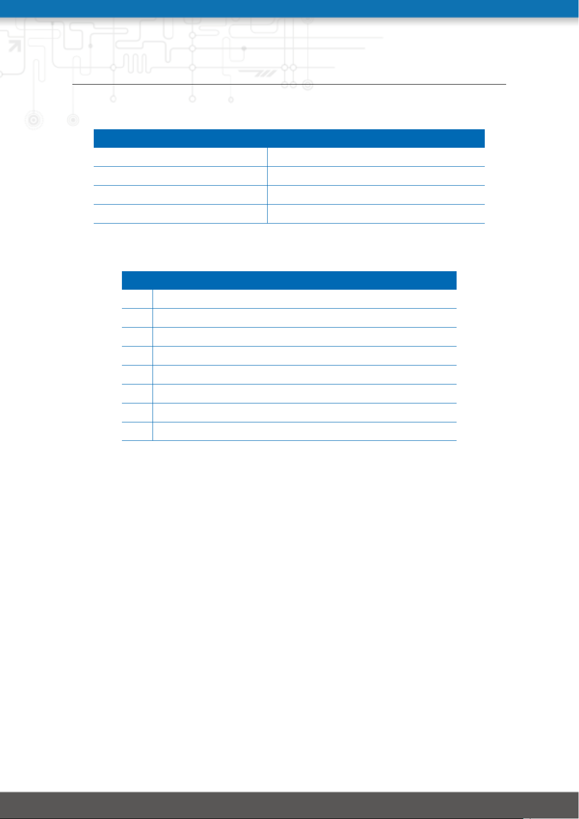
The Digital Output signal have the following specification:
Feature Specification
Number of ports 1x Digital Out (NO)
Max. continuous output current 1A
Max. switching output voltage 60VDC, 42 VAC ( Vrms)
Max. switching capacity 60W
Table 3.31.: Digital Output Specification
Pin Signal
1 Line IN +
2 Line IN −
3 Digital IN +
4 Digital OUT +
5 Digital OUT −
6 Digital IN −
7 Line OUT +
8 Line OUT −
Table 3.32.: Pin Assignments of RJ45 Audio-PTT Connector
26
Page 36
4. Installation
The NB2800 is designed for mounting it on a worktop or wall. Please consider the safety
instructions in chapter 2 and the environmental conditions in chapter 3.4.
The following precautions must be taken before installing a NB2800 router:
• Avoid direct solar radiation
• Protect the device from humidity, steam and aggressive fluids
• Guarantee sufficient circulation of air around the device
• The device is for indoor use only
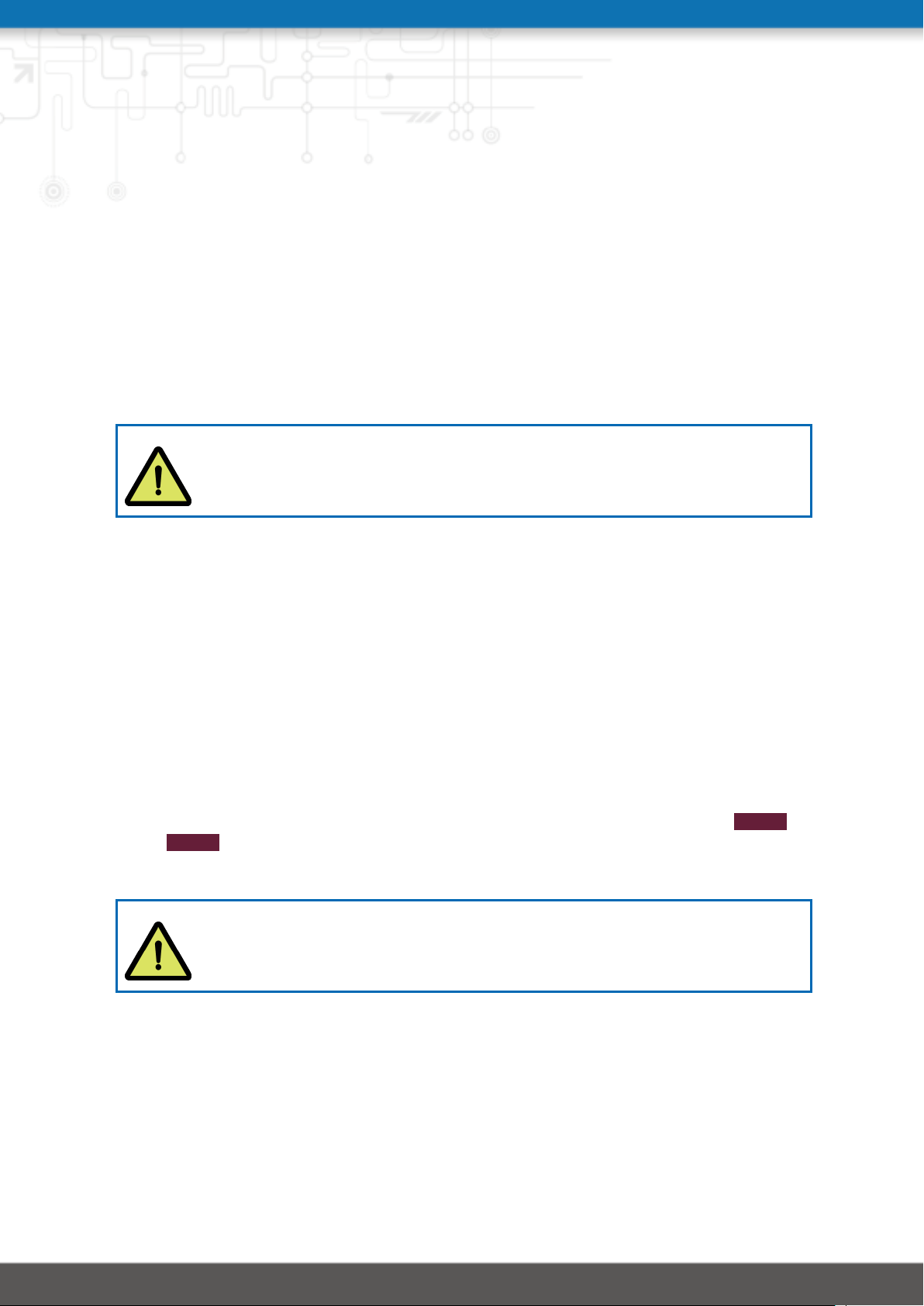
Attention: NetModule routers are not intended for the end consumer market.
The device must be installed and commissioned by a certified expert.
4.1. Installation of Micro-SIM Cards
Up to four Micro-SIM cards can be inserted in a NB2800 router.
SIM cards can be inserted by sliding it into one of the designated slots on the front panel.
You have to push the SIM card using a small paper clip (or similar) until it snaps into place.
To remove the SIM, you will need to push it again in the same manner. The SIM card will
then rebounce and can be pulled out.
SIMs can be assigned flexibly to any modem in the system. It is also possible to switch a
SIM to a different modem during operation, for instance if you want to use another provider
upon a certain condition. However, a SIM switch usually takes about 10-20 seconds which
can be bypassed (e.g. at bootup) if SIMs are installed reasonably. Using only a single SIM
with one modem, it should be preferably placed into the SIM 1 holder. For systems which
should operate two modems with two SIMs in parallel, we recommend to assign MOB 1 to
SIM 1, MOB 2 to SIM 2 and so on.
Further information about SIM configuration can be found in chapter 5.3.3.
Attention: After a SIM Switch the SIM Cover of the NB2800 router has to be
mounted again and screwed to get IP40 protection class.
4.2. Installation of the GSM/UMTS/LTE Antennas
NetModule routers will only operate efficiently in the cellular network if there is a good signal. A stub antenna will be suitable for most applications. However, in some circumstances
it might be necessary to use remote antennas together with an extended cable to reach a
27
Page 37
NB2800 User Manual 4.2
better location offering an adequate signal. In doubt, please contact us and we would be
pleased to assist you in figuring out the best matching antenna setup for your application.
Keep in mind that effects caused by Faraday cages such as large metal surfaces (elevators,
machine housings, etc.), close meshed iron constructions and others may reduce signal reception significantly.
The mounted antennas or antenna cables should be fixed with a wrench.
The following table shows how to connect the LTE/UMTS antennas. Generally, LTE antennas
use both, main and auxiliary ports, but UMTS requrires only main ports.
Antenna Port Type
MOB 1 A1 Main
MOB 1 A2 Auxiliary
MOB 2 A3 Main
MOB 2 A4 Auxiliary
MOB 3 A6 Main
MOB 3 A7 Auxiliary
MOB 4 A9 Main
MOB 4 A10 Auxiliary
Table 4.1.: LTE/UMTS antenna port types
Attention: Following points must be observed when installing the antennas:
• A minimum clearance of at least 40 cm between people and the antennas
must always be ensured.
• If one mobile inerface transmit simultaneously with other collocated radio
transmitters the separation distance of 20 cm between the antennas must
be maintained at all times.
• Antennas which are installed outside a building or the vehicle hull must limit
transient overvoltages (according to IEC 62368-1) to below a peak of 1500 V
through external protection circuits.
• Mobile communications antennas may have an amplification of maximum
2.5dBi, including the cable attenuation, in the relevant frequency range.
4.3. Installation of the WLAN Antennas
The following table shows how to connect the WLAN antennas. The number of attached
antennas can be configured in the software. If only one antenna is used, it must be attached
to the main port. However, for better diversity and thus better throughput and coverage,
we highly recommend using two antennas.
28
Page 38
NB2800 User Manual 4.2
Antenna Port Type
WLAN 1 A9 Main
WLAN 1 A10 Auxiliary
WLAN 2 A6 Main
WLAN 2 A7 Auxiliary
Table 4.2.: WLAN antenna port types
Attention: Following points must be observed when installing the antennas:
• A minimum clearance of at least 40 cm between people and the antennas
must always be ensured.
• If one WLAN inerface transmit simultaneously with other collocated radio
transmitters the separation distance of 20 cm between the antennas must
be maintained at all times.
• WLAN antennas must only be installed in buildings or within vehicle hulls.
• WLAN antennas may have an amplification of maximum 3dBi in the rele-
vant frequency range. WLAN antennas with a higher amplification may be
used with the NetModule router "Enhanced-RF-Configuration" software license and the antenna gain and cable attenuation that have been correctly
configured by certified specialized personnel.
4.4. Installation of the GNSS Antenna
The GNSS antenna must be mounted to the connector GNSS. Whether the antenna is an
active or passive GNSS antenna has to be configured in the software. We recommend active
GNSS antennas for highly accurate GNSS tracking.
Attention: Following points must be observed when installing the antenna:
• A minimum clearance of at least 40 cm between people and the antenna
must always be ensured.
• Antennas which are installed outside a building or the vehicle hull must limit
transient overvoltages (according to IEC 62368-1) to below a peak of 1500 V
through external protection circuits.
29
Page 39
NB2800 User Manual 4.2
4.5. Installation of the Local Area Network
Up to two 10/100/1000 Mbps Ethernet devices can be directly connected to the router, further devices can be attached via an addtional Ethernet switch. Please ensure that the connector has been plugged in properly to ETH and remains in a fixed state, you might otherwise experience sporadical link loss during operation. The Link/Act LED will lit up as soon as
the device has synced. If not, it might be necessary to configure a different link setting as
described in chapter 5.3.2.By default, the router is configured as a DHCP server and has the
IP address 192.168.1.1.
Attention:
Only a shielded Ethernet cable may be used.
4.6. Installation of the Power Supply & Delayed Power Off
The router can be powered with an external source supplying between 12 VDC and 48 VDC. It
is to be used with a certified (CE or equivalent) power supply, which must have a limited and
SELV circuit output. The router is now ready for getting engaged.
When no "delayed power off" is required, connect the supply voltage to both IGN and V+
pin. When using the "delayed power off" function, the V+ is connected directly to the battery
circuit and IGN is connected to the ignition circuit of the vehicle. Using this feature, the
router powers off a defined time (SW configurable) after the vehicle is turned off, instead of
an immediate shut down.
4.7. Installation of the Audio Interface
The audio interface (line out) is available on the PTT (Option Ap) and the Audio (Option A)
extension.
Attention:
Risk of hearing damage: Avoid the use of earphones or Headphones at high
volumes or over one longer period.
30
Page 40
5. Configuration
The following chapters give information about setting up the router and configuring its features as provided with system software 4.2.
NetModule provides regularly updated router software with new functions, bug
fixes and closed vulnerabilities. Please keep your router software up to date.
ftp://share.netmodule.com/router/public/system-software/
5.1. First Steps
NetModule routers can be easily set up by using the HTTP-based configuration interface,
called the Web Manager. It is supported by the latest web browsers (e.g. Microsoft Internet
Explorer 11, Mozilla Firefox 28.0, Safari 7 and many others). Please ensure to have JavaScript
turned on.
Any submitted configuration via the Web Manager will be applied immediately to the system
when pressing the Apply button. When configuring subsystems which require multiple steps
(for instance WLAN) you can use the Continue button to store any settings temporarily and
apply them at a later time. Please note, that those settings will be neglected at logout unless
applied.
You may also upload configuration files via SNMP, SSH, HTTP or USB in case you intend
to deploy a larger numbers of routers. Advanced users may also use the Command Line
Interface (CLI) and set configuration parameters directly.
The IP address of Ethernet1 is 192.168.1.1 and the Dynamic Host Configuration Protocol
(DHCP) is activated on the interface by default. The following steps need to be taken to
establish your first Web Manager session:
1. Connect the Ethernet port of your computer to the ETH 1 (Gigabit Ethernet) port of the
router using a shielded CAT6 cable with RJ45 connector.
2. If not yet activated, enable DHCP on your computer’s Ethernet interface so that an
IP address can be obtained automatically from the router. This usually takes a short
amount of time until your PC has received the corresponding parameters (IP address,
subnet mask, default gateway, name server). You may track the progress by having a
look to your network control panel and check whether your PC has correctly retrieved
an IP address of the range 192.168.1.100 to 192.168.1.199.
3. Launch your favorite web browser and point it to the IP address of the router (the URL
is http://192.168.1.1).
4. Please follow the instructions of the Web Manager for configuring the router. Most of
the menus are self-explanatory, further details are given in the following chapters.
5.1.1. Initial Access
In factory state you will be prompted for a new administrator password. Please choose a
password which is both, easy to remember but also robust against dictionary attacks (such
31
Page 41
NB2800 User Manual 4.2
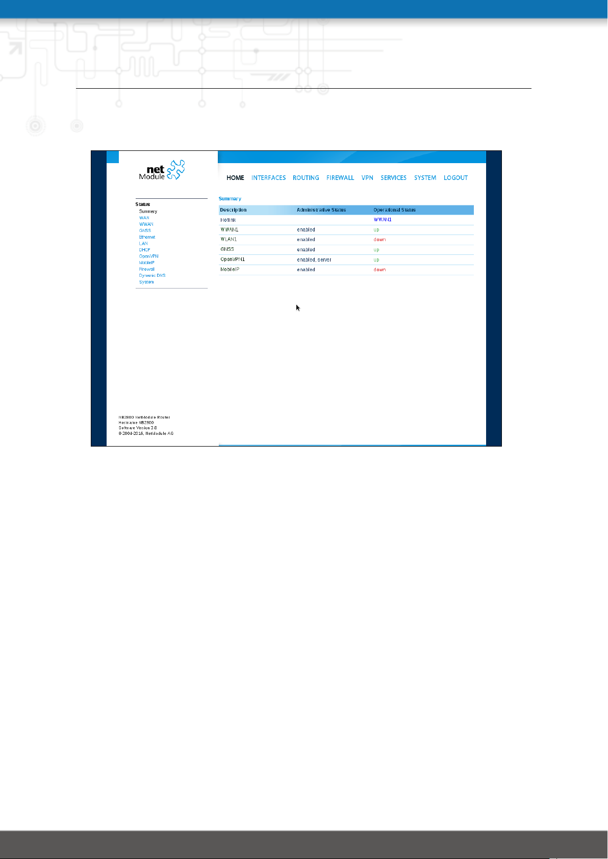
as one that contains numbers, letters and punctuation characters). The password shall have
a minimum length of 6 characters. It shall contain a minimum of 2 numbers and 2 letters.
Figure 5.1.: Initial Login
Please note that the admin password will be also applied for the root user which can be
used to access the device via the serial console, telnet, SSH or to enter the bootloader. You
may also configure additional users which will only be granted to access the summary page
or retrieve status information but not to set any configuration parameters.
A set of services (USB Autorun, CLI-PHP) are by default activated in factory state and will be
disabled as soon as the admin password has been set. They can be enabled again afterwards
in the relevant sections. Other services (SSH, Telnet, Console) can be accessed in factory
state by providing an empty or no password.
5.1.2. Recovery
Following actions might be taken in case the router has been misconfigured and cannot be
reached anymore:
1. Factory Reset: You can initiate a reset back to factory settings via the Web Manager,
by running the command factory-reset or by pressing the reset button. The latter
would require a slim needle or paper clip which must be inserted into the hole to
the right of the SIM 4 slot . The button must be hold pressed for up to 5 seconds
until all LEDs flash up.
2. Serial Console Login: It is also possible to log into the system via the serial port. This
32
Page 42

NB2800 User Manual 4.2
would require a terminal emulator (such as PuTTY or HyperTerminal) and an RS232
connection (115200 8N1) attached to the serial port of your local computer. You will
also see the kernel messages at bootup there.
3. Recovery Image: In severe cases we can provide a recovery image on demand which
can be loaded into RAM via TFTP and executed. It offers a minimal system image for
running a software update or doing other modifications. You will be provided with two
files, recovery-image and recovery-dtb, which must be placed in the root directory of a
TFTP server (connected via LAN1 and address 192.168.1.254). The recovery image can
be launched from the boot-loader using a serial connection. You will have to stop the
boot process by pressing s and enter the bootloader. You can then issue run recovery
to load the image and start the system which can be accessed via HTTP/SSH/Telnet and
its IP address 192.168.1.1 afterwards. This procedure can be also initiated by holding
the factory reset button longer than 15 seconds.
33
Page 43
NB2800 User Manual 4.2
5.2. HOME
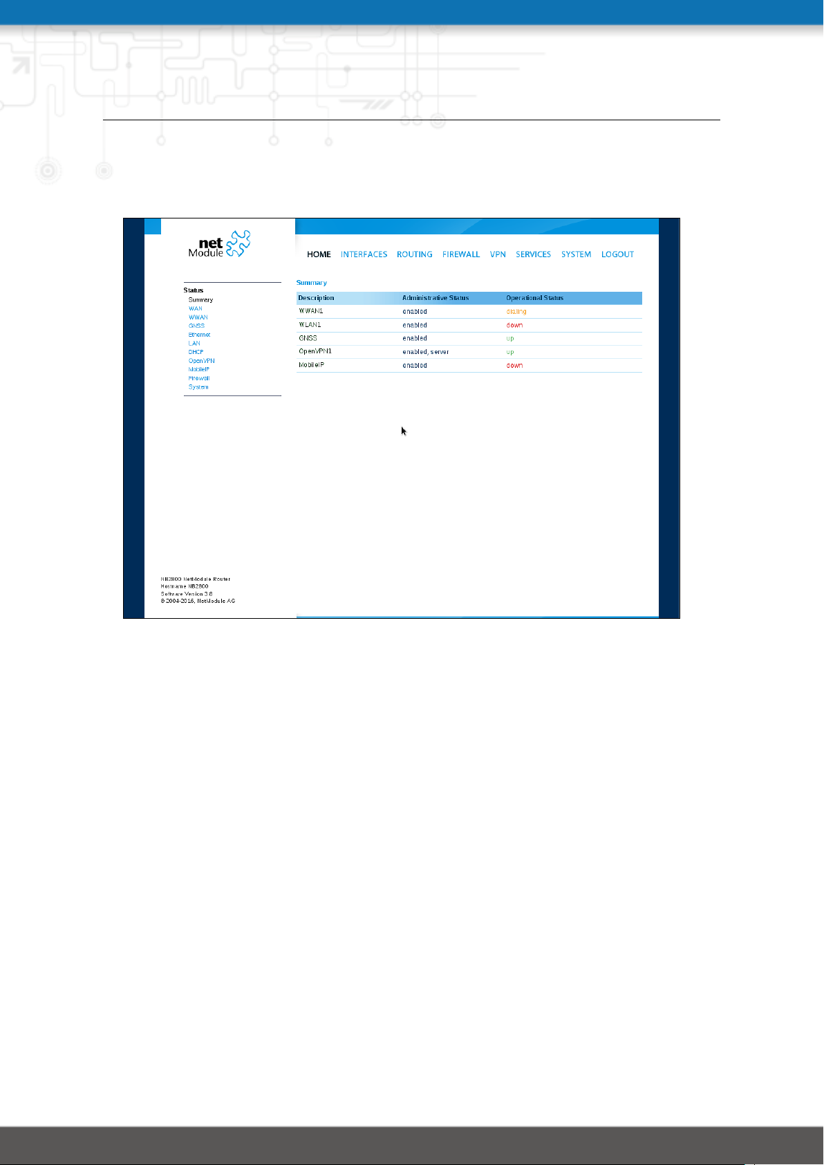
This page provides a status overview of enabled features and connections.
Figure 5.2.: Home
Summary
This page offers a short summary about the administrative and operational status of the
router’s interfaces.
WAN
This page offers details about any enabled Wide Area Network (WAN) links (such as the IP
addresses, network information, signal strength, etc.) The information about the amount of
downloaded/uploaded data is stored in non-volatile memory, thus survive a reboot of the
system.
The counters can be reset by pressing the Reset button.
WWAN
This page shows information about modems and their network status.
WLAN
The WLAN page offers details about the enabled WLAN interfaces when operating in accesspoint mode. This includes the SSID, IP and MAC address and the currently used frequency
and transmit power of the interface as well as the list of associated stations.
34
Page 44

NB2800 User Manual 4.2
GNSS
This page displays the position status values, such as latitude/longitude, the satellites in view
and more details about the used satellites.
Ethernet
This page shows information about the Ethernet interfaces and packet statistics information.
LAN
This page shows information about the LAN interfaces plus the neighborhood information.
DHCP
This page offers details about any activated DHCP service, including a list of issued DHCP
leases.
OpenVPN
This page provides information about the OpenVPN tunnel status.
IPSec
This page provides information about the IPsec tunnel status.
PPTP
This page provides information about the PPTP tunnel status.
GRE
This page provides information about the GRE tunnel status.
MobileIP
This page provides information about Mobile IP connections.
Firewall
This page offers information about any firewall rules and their matching statistics. It can be
used to debug the firewall.
QoS
This page provides information about the used QoS queues.
BGP
This page provides information about the Border Gateway Protocol.
OSPF
This page provides information about the Open Shortest Path First routing protocol.
DynDNS
This page provides information about Dynamic DNS.
35
Page 45

NB2800 User Manual 4.2
System Status
The system status page displays various details of your NB2800 router, including system
details, information about mounted modules and software release information.
SDK
This section will list all webpages generated by SDK scripts.
36
Page 46
NB2800 User Manual 4.2
5.3. INTERFACES
5.3.1. WAN
Link Management
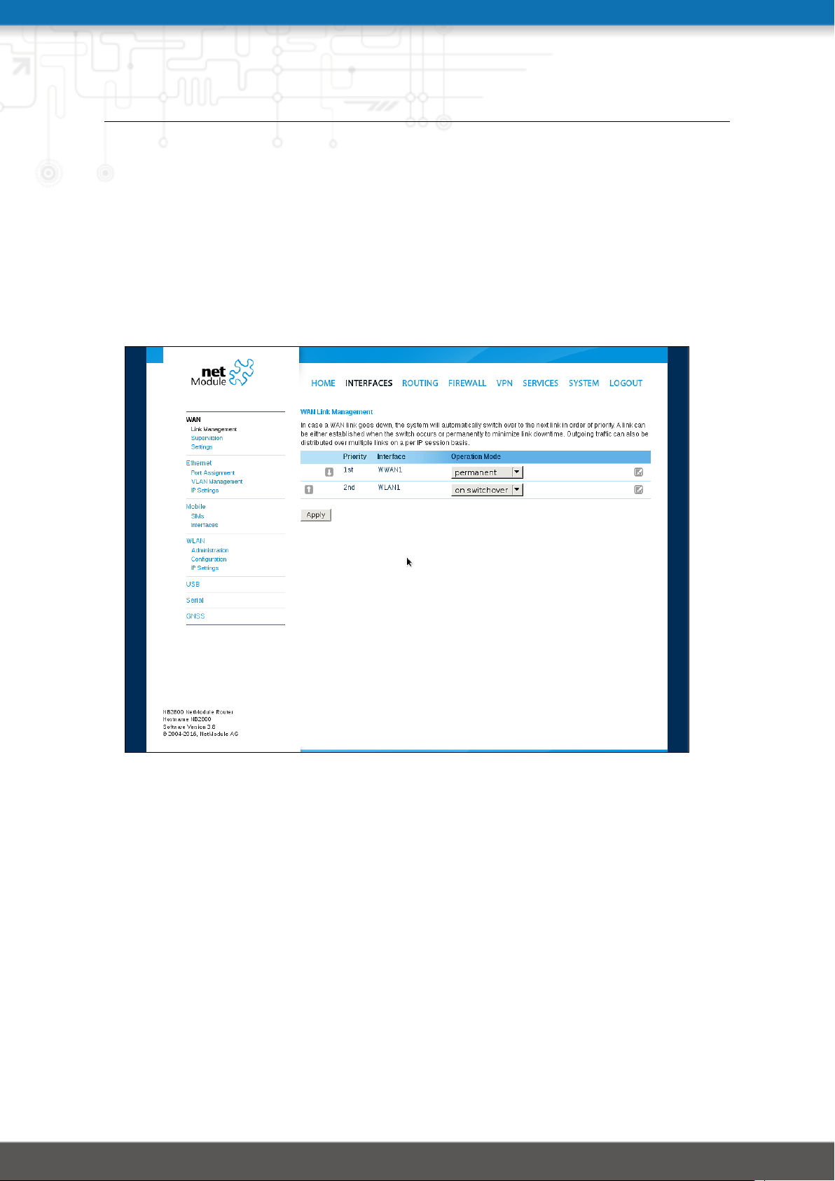
Depending on your hardware model, WAN links can be made up of either Wireless Wide Area
Network (WWAN), Wireless LAN (WLAN), Ethernet or PPP over Ethernet (PPPoE) connections.
Please note that each WAN link has to be configured and enabled in order to appear on this
page.
Figure 5.3.: WAN Links
37
Page 47

NB2800 User Manual 4.2
In general, a link will be only dialed or declared as up if the following prerequisites are met:
Condition WWAN WLAN ETH PPPoE
Modem is registered X
Registered with valid service type X
Valid SIM state X
Sufficient signal strength X X
Client is associated X
Client is authenticated X
Valid DHCP address retrieved X X X X
Link is up and holds address X X X X
Ping check succeeded X X X X
The menu can be used further to prioritize your WAN links. The highest priority link which
has been established successfully will become the so-called hotlink which holds the default
route for outgoing packets.
In case a link goes down, the system will automatically switch over to the next link in the
priority list. You can configure each link to be either established when the switch occurs or
permanently in order to minimize link downtime.
Parameter WAN Link Priorities
1st priority The primary link which will be used whenever possible.
2nd priority The first fallback link, it can be enabled permanently or being
dialed as soon as Link 1 goes down.
3rd priority The second fallback link, it can be enabled permanently or be-
ing dialed as soon as Link 2 goes down.
4th priority The third fallback link, it can be enabled permanently or being
dialed as soon as Link 3 goes down.
Links are being triggered periodically and put to sleep in case it was not possible to establish
them within a certain amount of time. Hence it might happen that permanent links will
be dialed in background and replace links with lower priority again as soon as they got
established. In case of interfering links sharing the same resources (for instance in dual-SIM
operation) you may define a switch-back interval after which an active hotlink is forced to go
down in order to let the higher-prio link getting dialed again.
We recommend to use the permanent operation mode for WAN links in general. However, in
case of time-limited mobile tariffs for instance, the switchover mode might be applicable.
By using the distributed mode, it is possible to distribute outgoing traffic over multiple
WAN links based on their weight ratio.
38
Page 48
NB2800 User Manual 4.2
Attention:
You can have concurrent WWAN links which share a common recource like one
WWAN module using SIM cards of different providers. In that case it would
not be possible to find out if the link with the higher priority is available without putting down the low priority link. Therefor such a link will behave like a
switchover even if configured as permanent.
For mobile links, it is further possible to pass through the WAN address towards a local host
(also called Drop-In or IP Pass-through). In particular, the first DHCP client will receive the
public IP address. More or less, the system acts like a modem in such case which can be
helpful in case of firewall issues. Once established, the Web Manager can be reached over
port 8080 using the WAN address but still over the LAN1 interface using port 80.
Parameter WAN Link Operation Modes
disabled Link is disabled
permanent Link is being established permanently
on switchover Link is being established on switchover, it will be dialled if pre-
vious links failed
distributed Link is member of a load distribution group
Parameter WAN Link Settings
Operation mode The operation mode of the link
Weight The weight ratio of a distributed link
Switch-back Specifies the switch-back condition of a switchover link and the
time after an active hotlink will be teared down
Bridging interface
1
If WLAN client, the LAN interface to which the WAN link should
be bridged.
NetModule routers provide a feature called IP pass-through (aka Drop-In mode). If enabled,
the WAN address will be be passed-through to the first DHCP client of the specified LAN
interface. As Ethernet-based communication requires additional addresses, we pick an appropriate subnet to talk to the LAN host. In case this overlaps with other addresses of your
WAN network, you may optionally specify the network given by your provider to avoid any
address conflicts.
Parameter IP Pass-Through Settings
IP Pass-through Enables or disables IP pass-through
1
This options requires an Access Point with four address frame format support.
39
Page 49

NB2800 User Manual 4.2
Parameter IP Pass-Through Settings
Interface Specifies the interface on which the address shall be passed-
through
WAN network Specifies the WAN network
WAN netmask Specifies the WAN netmask
40
Page 50

NB2800 User Manual 4.2
WAN Settings
This page can be used to configure WAN specific settings like the Maximum Segment Size
(MSS). The MSS corresponds to the largest amount of data (in bytes) that the router can
handle in a single, unfragmented TCP segment. In order to avoid any negative side effects
the number of bytes in the data segment and the headers must not add up to more than the
number of bytes in the Maximum Transmission Unit (MTU). The MTU can be configured per
each interface and corresponds to the largest packet size that can be transmitted.
Figure 5.4.: WAN Settings
Parameter TCP MSS Settings
MSS adjustment Enable or disable MSS adjustment on WAN interfaces.
Maximum segment size Maximum number of bytes in a TCP data segment.
41
Page 51
NB2800 User Manual 4.2
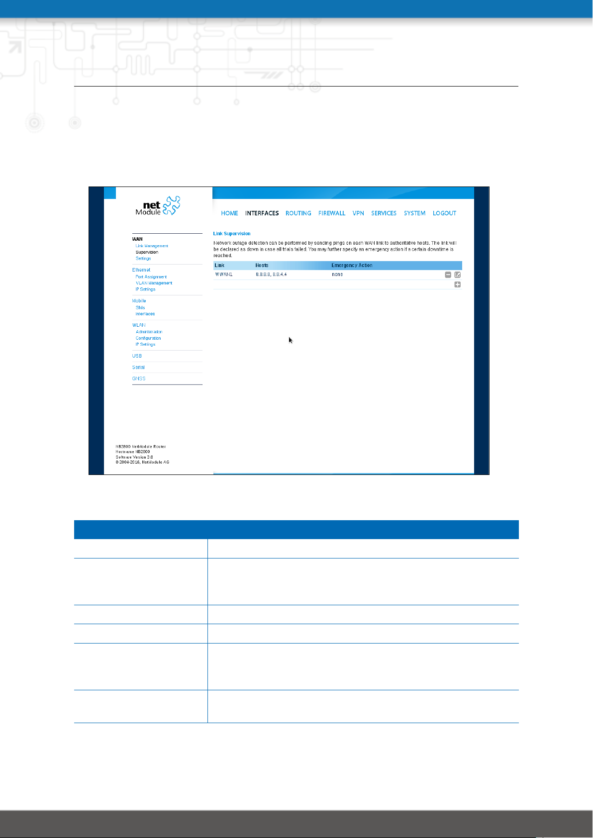
Supervision
Network outage detection on a per-link basis can be performed by sending pings on each
link to some authoritative hosts. A link will be declared as down in case all trials have failed
and only as up if at least one host can be reached.
Figure 5.5.: Link Supervision
Parameter Supervision Settings
Link The WAN link to be monitored (can be ANY)
Mode Specifies whether the link shall only be monitored if being up
(e.g. for using a VPN tunnel) or if connectivity shall be also
validated at connection establishment (default)
Primary host The primary host to be monitored
Secondary host The secondary host to be monitored (optional)
Ping timeout The amount of time in milliseconds a response for a single
ping can take, consider to increase this value in case of slow
and tardy links (such as 2G connections)
Ping interval The interval in seconds at which pings are transmitted on each
interface
42
Page 52
NB2800 User Manual 4.2
Parameter Supervision Settings
Retry interval The interval in seconds at which pings are re-transmitted in
case a first ping failed
Max. number of failed trials
Emergency action The emergency action which should be taken after a maximum
The maximum number of failed ping trials until the link will be
declared as down
downtime has been reached. Using reboot would perform a
reboot of the system, restart link services will restart all
link-related applications including a reset of the modem.
43
Page 53
NB2800 User Manual 4.2
5.3.2. Ethernet
NB2800 routers ship with 2 dedicated Gigabit Ethernet ports (ETH1 and ETH2) and an additional extension port which can be linked via RJ45 connectors.
ETH1 usually forms the LAN1 interface which should be used for LAN purposes. Other interfaces can be used to connect other LAN segments or for configuring a WAN link. The LAN10
interface will be available as soon as a pre-configured USB Ethernet device has been plugged
in.
Ethernet Port Assignment
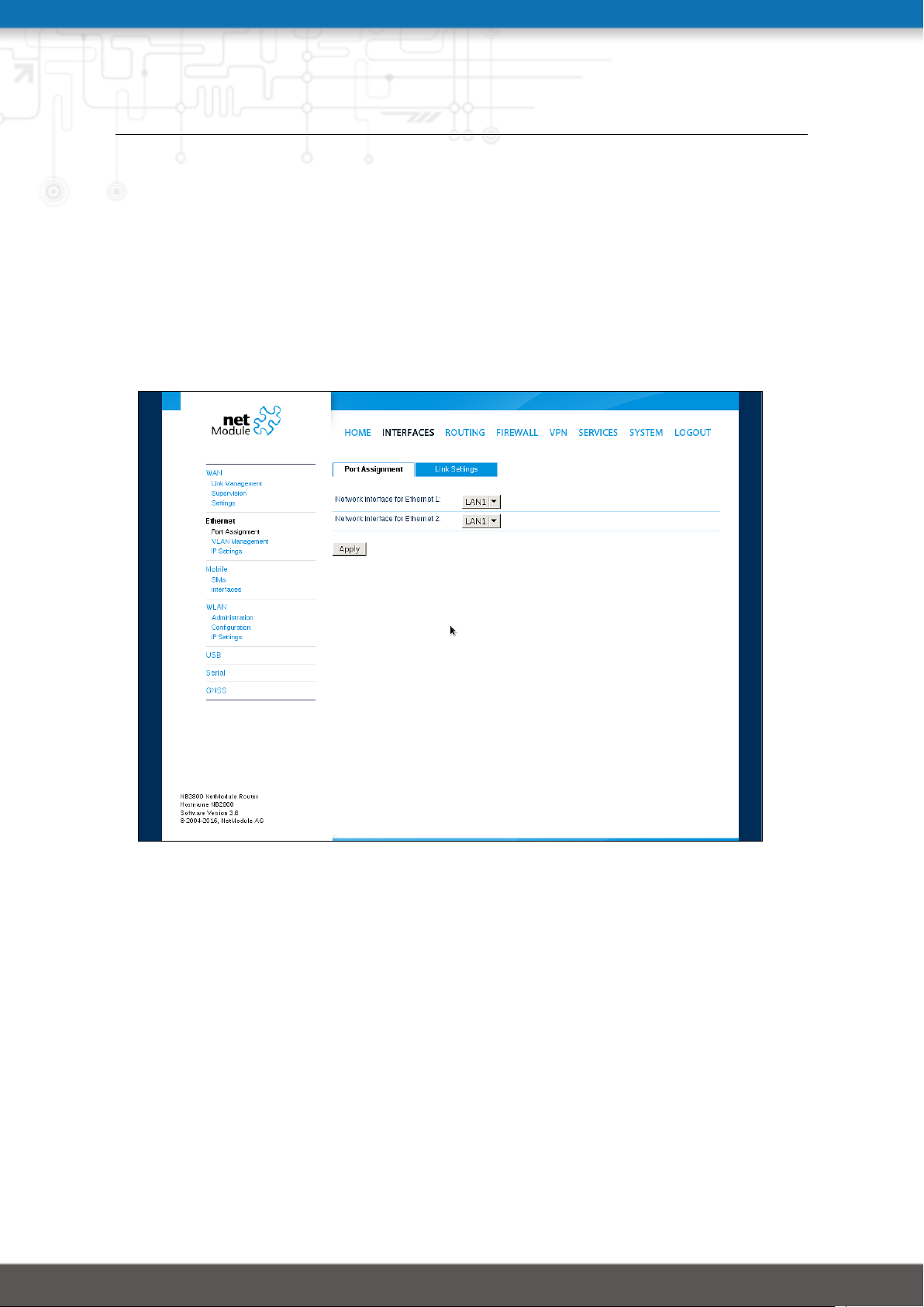
Figure 5.6.: Ethernet Ports
This menu can be used to individually assign each Ethernet port to a LAN interface, just in
case you want to have different subnets per port or use one port as WAN interface. You may
assign multiple ports to the same interface.
44
Page 54
NB2800 User Manual 4.2
Please note that NB2800 routers don’t have a switch but single PHY ports. If both ports are
assigned to the same LAN interface the ports will be bridged by software.
The following options exist:
Parameter Ethernet Softbridge Settings
Enable bridge filtering If enabled, the firewall rules will also match packets between
the ports
Enable RSTP If enabled, the Rapid Spanning Tree Protocol (IEEE 802.1D-
2004) rather than the Spanning Tree Protocol will be activated
Ethernet Link Settings
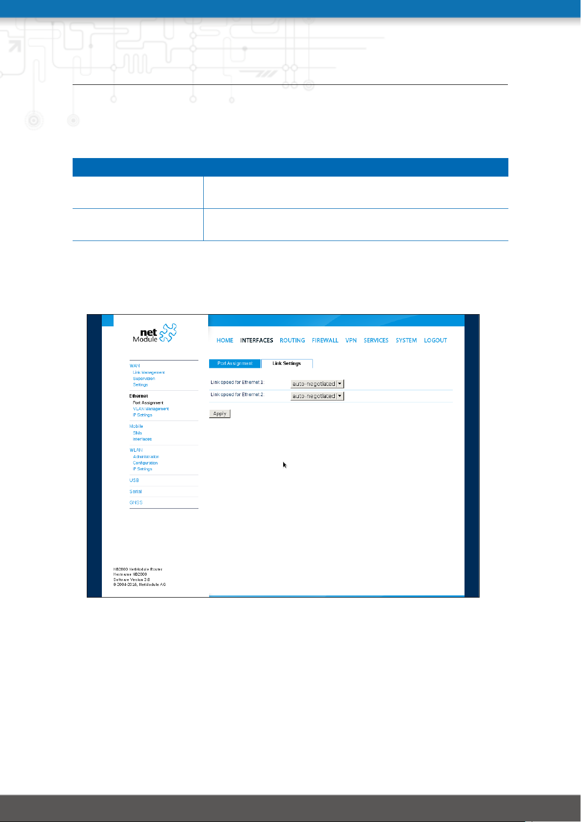
Figure 5.7.: Ethernet Link Settings
Link negotiation can be set for each Ethernet port individually. Most devices support autonegotiation which will configure the link speed automatically to comply with other devices
in the network. In case of negotiation problems, you may assign the modes manually but it
has to be ensured that all devices in the network utilize the same settings then.
45
Page 55
NB2800 User Manual 4.2
VLAN Management
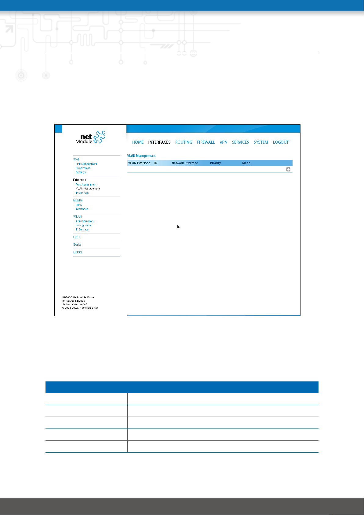
NetModule routers support Virtual LAN according to IEEE 802.1Q which can be used to create virtual interfaces on top of an Ethernet interface. The VLAN protocol inserts an additional
header to Ethernet frames carrying a VLAN Identifier (VLAN ID) which is used for distributing
the packets to the associated virtual interface. Any untagged packets, as well as packets with
an unassigned ID, will be distributed to the native interface.
Figure 5.8.: VLAN Management
In order to form a distinctive subnet, the network interface of a remote LAN host must be
configured with the same VLAN ID as defined on the router. Further, 802.1P introduces a
priority field which influences packet scheduling in the TCP/IP stack.
The following priority levels (from lowest to highest) exist:
Parameter VLAN Priority Levels
0 Background
1 Best Effort
2 Excellent Effort
3 Critical Applications
4 Video (< 100 ms latency and jitter)
46
Page 56

NB2800 User Manual 4.2
Parameter VLAN Priority Levels
5 Voice (< 10 ms latency and jitter)
6 Internetwork Control
7 Network Control
47
Page 57
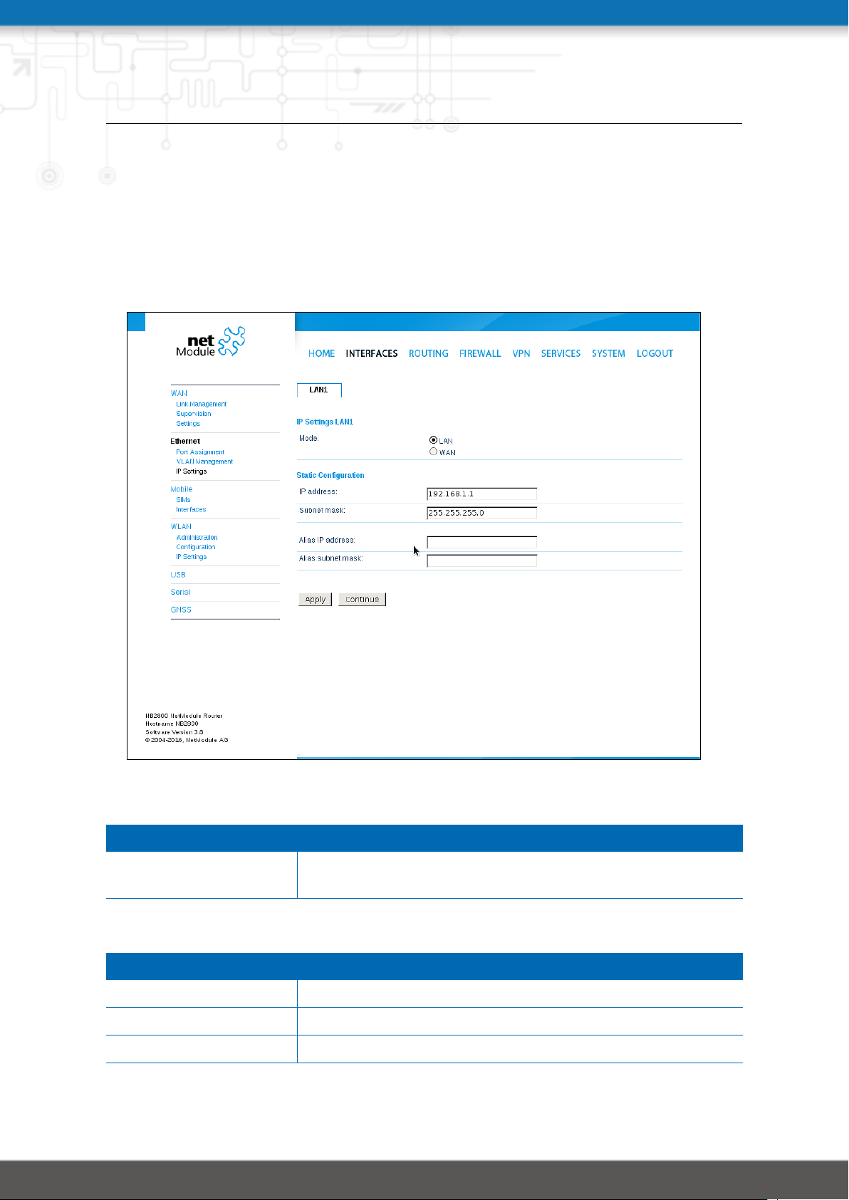
NB2800 User Manual 4.2
IP Settings
This page can be used to configure IP addressing for your LAN/WAN Ethernet interfaces. In
addition to the primary IP address/subnet mask you may define an additional IP address
alias on the interface.
Please keep in mind that the DNS servers can be set globally in the DNS server configuration
menu. But as soon as a link comes up it will use the interface-specific name-servers (e.g. the
ones being retrieved over DHCP) and update the resolver configuration accordingly.
Figure 5.9.: LAN IP Configuration
Parameter LAN IP Settings
Mode Defines whether this interface is being used as LAN or WAN
interface
When running in LAN mode, the interface may be configured with the following settings:
Parameter LAN IP Settings
IP address The IP interface address
Subnet mask The subnet mask for this interface
Alias IP address The alias IP interface address
48
Page 58

NB2800 User Manual 4.2
Parameter LAN IP Settings
Alias subnet mask The alias subnet mask for this interface
When running in WAN mode, the interface may be configured with the following settings:
Parameter WAN IP Settings
WAN mode The WAN operation mode, defines whether the interface
should run as DHCP client, statically configured or over PPPoE.
MTU The Maximum Transmission Unit for the interface, if provided
it will specify the largest size of a packet transmitted on the
interface.
When running as DHCP client, no further configuration is required because all IP-related
settings (address, subnet, gateway, DNS server) will be retrieved from a DHCP server in the
network. You may also define static values but caution has to be taken to assign an unique
IP address as it would otherwise raise IP conflicts in the network.
PPPoE is commonly used when communicating with another WAN access device (like a DSL
modem). The following settings can be applied:
Parameter PPPoE Configuration
User name PPPoE user name for authenticating at the access device
Password PPPoE password for authenticating at the access device
Service name Specifies the service name set of the access concentrator and
can be left blank unless you have multiple services on the
same physical network and need to specify the one you want
to connect to.
Access concentrator
name
The name of the concentrator (the PPPoE client will connect to
any access concentrator if left blank)
49
Page 59
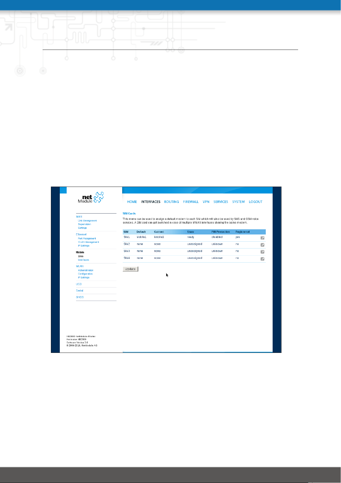
NB2800 User Manual 4.2
5.3.3. Mobile
Modems
Configuration
This page lists all available WWAN modems. They can be disabled on demand.
Query
This page allows you to send Hayes AT commands to the modem. Besides the 3GPP-conforming
AT command-set further modem-specific commands can be applicable which we can provide
on demand. Some modems also support running Unstructured Supplementary Service Data
(USSD) requests, e.g. for querying the available balance of a prepaid account.
SIMs
Figure 5.10.: SIMs
The SIM page gives an overview about the available SIM cards, their assigned modems and
the current state. Once a SIM card has been inserted, assigned to a modem and successfully
unlocked, the card should remain in state ready and the network registration status should
have turned to registered. If not, please double-check your PIN.
Please keep in mind that registering to a network usually takes some time and depends on
signal strength and possible radio interferences. You may hit the Update button at any time
in order to restart PIN unlocking and trigger another network registration attempt.
50
Page 60

NB2800 User Manual 4.2
Under some circumstances (e.g. in case the modem flaps between base stations) it might
be necessary to set a specific service type or assign a fixed operator. The list of operators
around can be obtained by initiating a network scan (may take up to 60 seconds). Further
details can be retrieved by querying the modem directly, a set of suitable commands can be
provided on request.
51
Page 61

NB2800 User Manual 4.2
Configuration
A SIM card is generally assigned to a default modem but might be switched, for instance if
you set up two WWAN interfaces with one modem but different SIM cards.
Close attention has to be paid when other services (such as SMS or Voice) are operating on
that modem, as a SIM switch will naturally affect their operation.
The following settings can be applied:
Parameter WWAN SIM Configuration
PIN code The PIN code for unlocking the SIM card
PUK code The PUK code for unlocking the SIM card (optional)
Default modem The default modem assigned to this SIM card
Preferred service The preferred service to be used with this SIM card. Remem-
ber that the link manager might change this in case of different
settings. The default is to use automatic, in areas with interfering base stations you can force a specific type (e.g. 3G-only)
in order to prevent any flapping between the stations around.
Registration mode The desired registration mode
Network selection Defines which network shall be selected. This can be bound
to a specific LAI which can be retrieved by running a network
scan.
52
Page 62
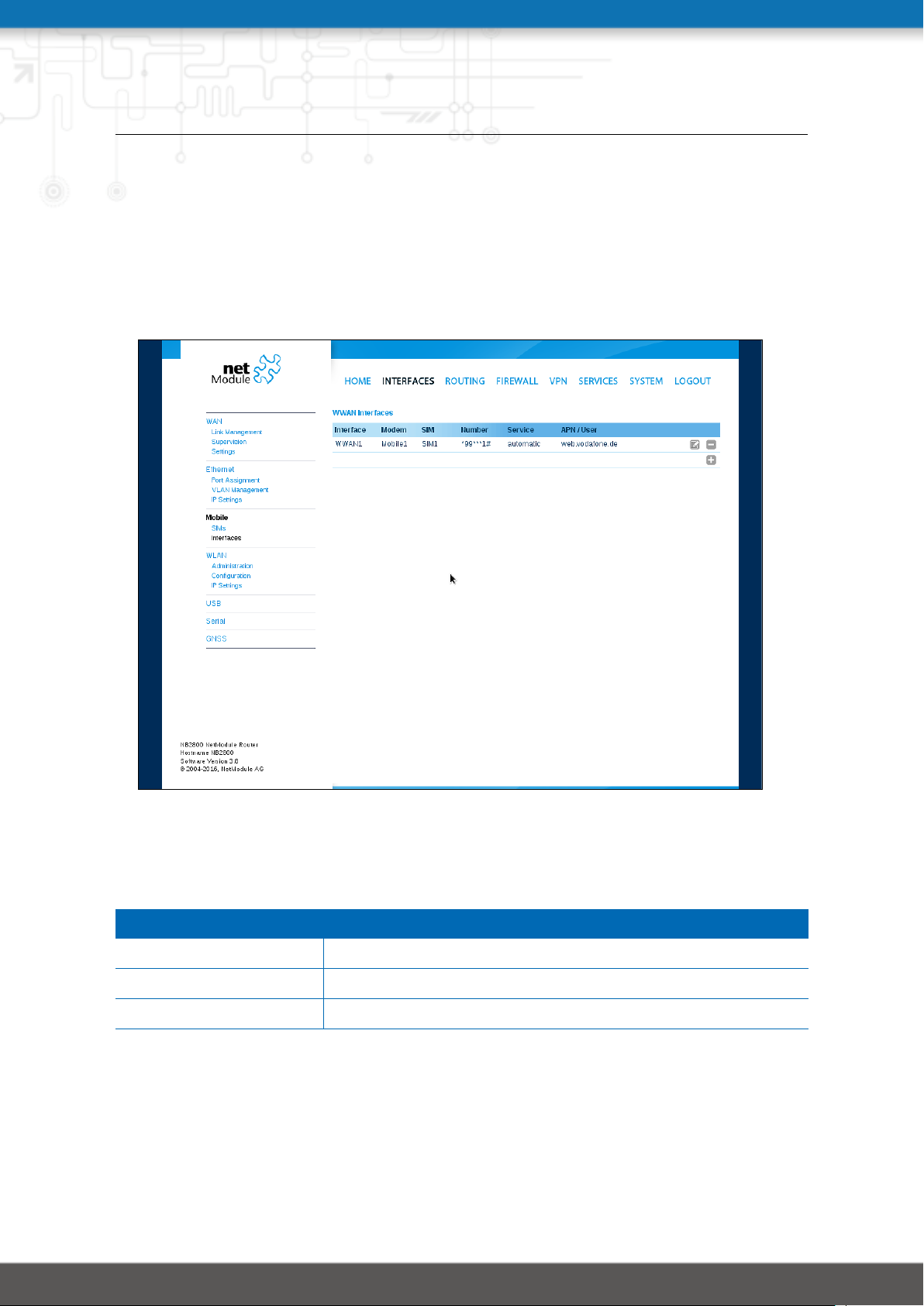
NB2800 User Manual 4.2
WWAN Interfaces
This page can be used to manage your WWAN interfaces. The resulting link will pop up
automatically as WAN link once an interface has been added. Please refer to chapter 5.3.1
for how to manage them.
The Mobile LED will be blinking during the connection establishment process and goes on
as soon as the connection is up. Refer to section 5.8.7 or consult the system log files for
troubleshooting the problem in case the connection did not come up.
Figure 5.11.: WWAN Interfaces
The following mobile settings are required:
Parameter WWAN Mobile Parameters
Modem The modem to be used for this WWAN interface
SIM The SIM card to be used for this WWAN interface
Service type The required service type
Please note that these settings supersede the general SIM based settings as soon as the link
is being dialed.
53
Page 63

NB2800 User Manual 4.2
Generally, the connection settings are derived automatically as soon as the modem has
registered and the network provider has been found in our database. Otherwise, it will be
required to configure the following settings manually:
Parameter WWAN Connection Parameters
Phone number The phone number to be dialed, for 3G+ connections this com-
monly refers to be *99***1#. For circuit-switched 2G connections you can enter the fixed phone number to be dialed in
international format (e.g. +41xx).
Access point name The access point name (APN) being used
Authentication The authentication scheme being used, if required this can be
PAP or/and CHAP
Username The user-name used for authentication
Password The password used for authentication
Furtheron, you may configure the following advanced settings:
Parameter WAN Advanced Parameters
Required signal strength Sets a minimum required signal strength before the connec-
tion is dialed
Home network only Determines whether the connection should only be dialed
when registered to a home network
Negotiate DNS Specifies whether the DNS negotiation should be performed
and the retrieved name-servers should be applied to the system
Call to ISDN Has to be enabled in case of 2G connections talking to an ISDN
modem
Header compression Enables or disables 3GPP header compression which may im-
prove TCP/IP performance over slow serial links. Has to be
supported by your provider.
Data compression Enables or disables 3GPP data compression which shrinks the
size of packets to improve throughput. Has to be supported
by your provider.
Client address Specifies a fixed client IP address if assigned by the provider
MTU The Maximum Transmission Unit for this interface
54
Page 64
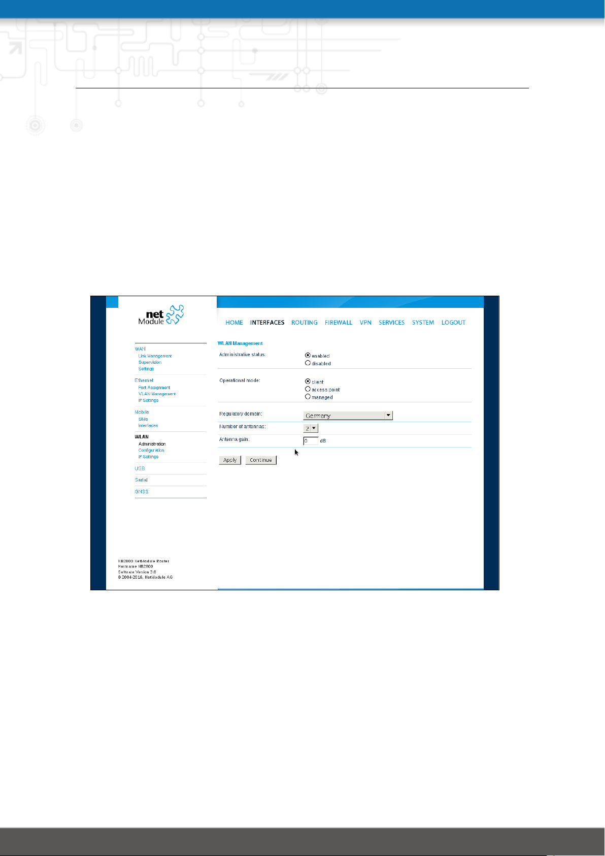
NB2800 User Manual 4.2
5.3.4. WLAN
WLAN Management
In case your router is shipping with a WLAN (or Wi-Fi) module you can operate it either
as client, access point, mesh point or certain dual modes. As a client it can create an
additional WAN link which for instance can be used as backup link. As access point, it can
form another LAN interface which can be either bridged to an Ethernet-based LAN interface or create a self-contained IP interface which can be used for routing and to provide
services (such as DHCP/DNS/NTP) in the same way like an Ethernet LAN interface does. As
mesh point, it can create a wireless mesh network to provide a backhaul connectivity with
dynamic path selection. As dual mode, it is possible to run access point and client or mesh
point and access point functionality on the same radio module.
Figure 5.12.: WLAN Management
If the administrative status is set to disabled, the module will be powered off in order to
reduce the overall power consumption. Regarding antennas, we generally recommend using
two antennas for better coverage and throughput. A second antenna is definitely mandatory
if you want to achieve higher throughput rates as in 802.11n.
A WLAN client and a mesh point will automatically became a WAN link and can be managed as described in chapter 5.3.1.
55
Page 65
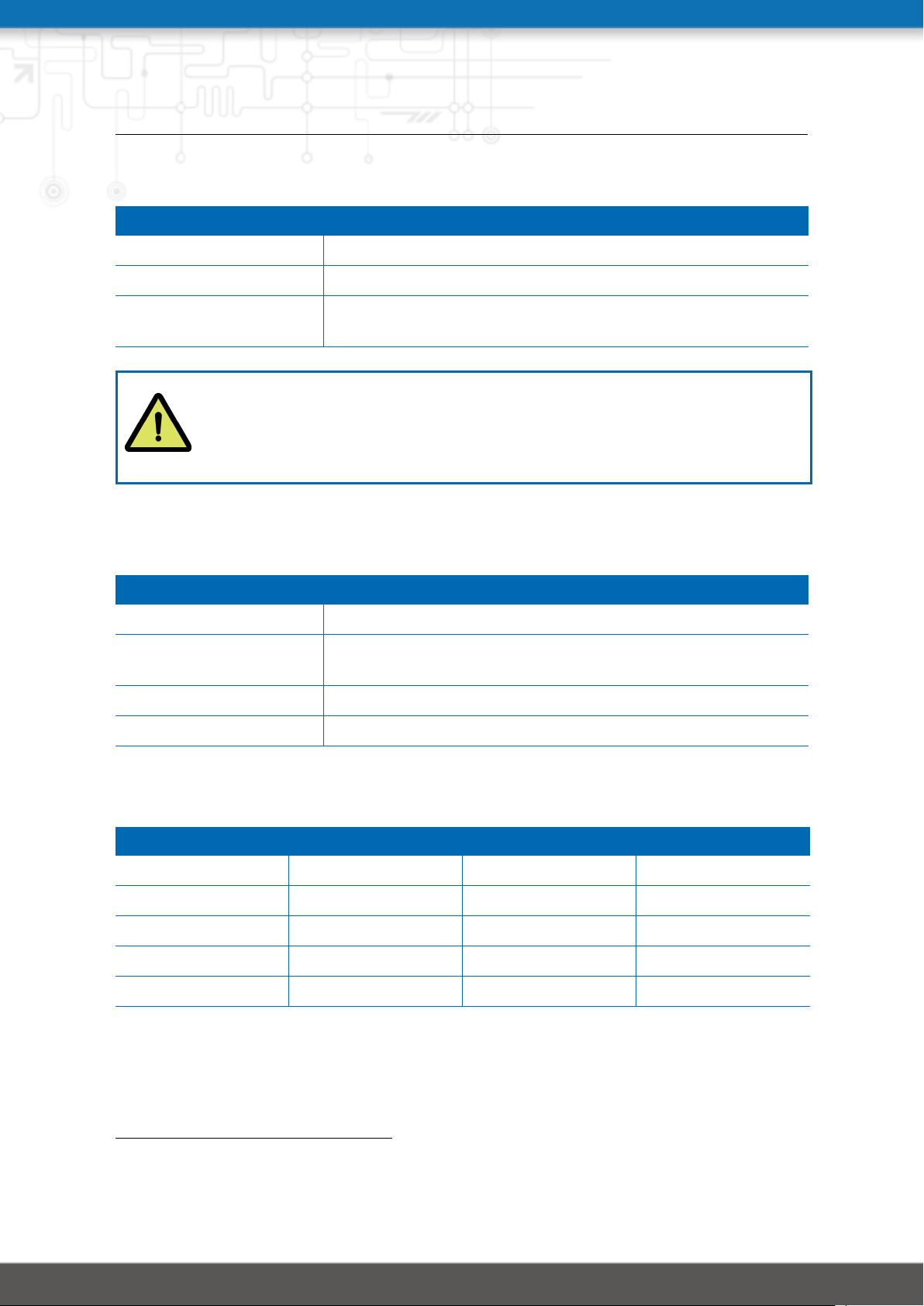
NB2800 User Manual 4.2
Configurable parameters for access-point, client mode, mesh point and any dual mode:
Parameter WLAN Management
Regulatory Domain Select the country the Router operates in
Number of antennas Set the number of connected antennas
Antenna gain Specify the antenna gain for the connected antennas. Please
refer to the antennas datasheet for the correct gain value.
Warning
Please be aware that any inappropriate parameters can lead to an infringement
of conformity regulations.
Running as access point or dual mode, you can further configure the following settings:
Parameter WLAN Management
Operation type Specifies the desired IEEE 802.11 operation mode
Radio band Selects the radio band to be used for connections, depending
on your module it could be 2.4 or 5 GHz
Bandwidth Specify the channel bandwidth operation mode
Channel Specifies the channel to be used
Available operation modes are:
Standard Frequencies Bandwidth Data Rate
802.11a 5 GHz 20 MHz 54 Mbit/s
802.11b 2.4 GHz 20 MHz 11 Mbit/s
802.11g 2.4 GHz 20 MHz 54 Mbit/s
802.11n 2.4/5 GHz 20/40 MHz 300 Mbit/s
802.11ac
2
5 GHz 20/40/80 MHz 866.7 Mbit/s
Table 5.20.: IEEE 802.11 Network Standards
2
Only available for NetModule Routers NB2800, NB3701, NB3711 and NB3800
56
Page 66
NB2800 User Manual 4.2
Running as mesh point, you can further configure the following settings:
Parameter WLAN Mesh-Point Management
Operation type Specifies the desired IEEE 802.11 operation mode
Radio band Selects the radio band to be used for connections, depending
on your module it could be 2.4 or 5 GHz
Channel Specifies the channel to be used
Note: NetModule Routers with 802.11n and 802.11ac support 2x2 MIMO
57
Page 67

NB2800 User Manual 4.2
Prior to setting up an access point, it is always a good idea to run a network scan for getting
a list of neighboring WLAN networks and then choose the less interfering channel. Please
note that two adequate channels are required for getting good throughputs with 802.11n
and a bandwidth of 40 MHz.
WLAN Configuration
Running in client mode, it is possible to connect to one ore more remote access-points.
The system will switch to the next network in the list in case one goes down and return to
the highest-prioritized network as soon as it comes back. You can perform a WLAN network
scan and pick the settings from the discovered information directly. The authentication
credentials have to be obtained by the operator of the remote access point.
Parameter WLAN Client Configuration
SSID The network name (called SSID)
Security mode The desired security mode
WPA/WPA2 mixed mode WPA2 should be preferred over WPA1, running WPA/WPA2
mixed-mode offers both.
WPA cipher The WPA cipher to be used, the default is to run both (TKIP and
CCMP)
Identity The identity used for WPA-RADIUS and WPA-EAP-TLS
Passphrase The passphrase used for authentication with WPA-PSK, other-
wise the key passphrase for WPA-EAP-TLS
Force PMF Enables Protected Management Frames
Required signal strength Required signal strength to esablish the connection
58
Page 68
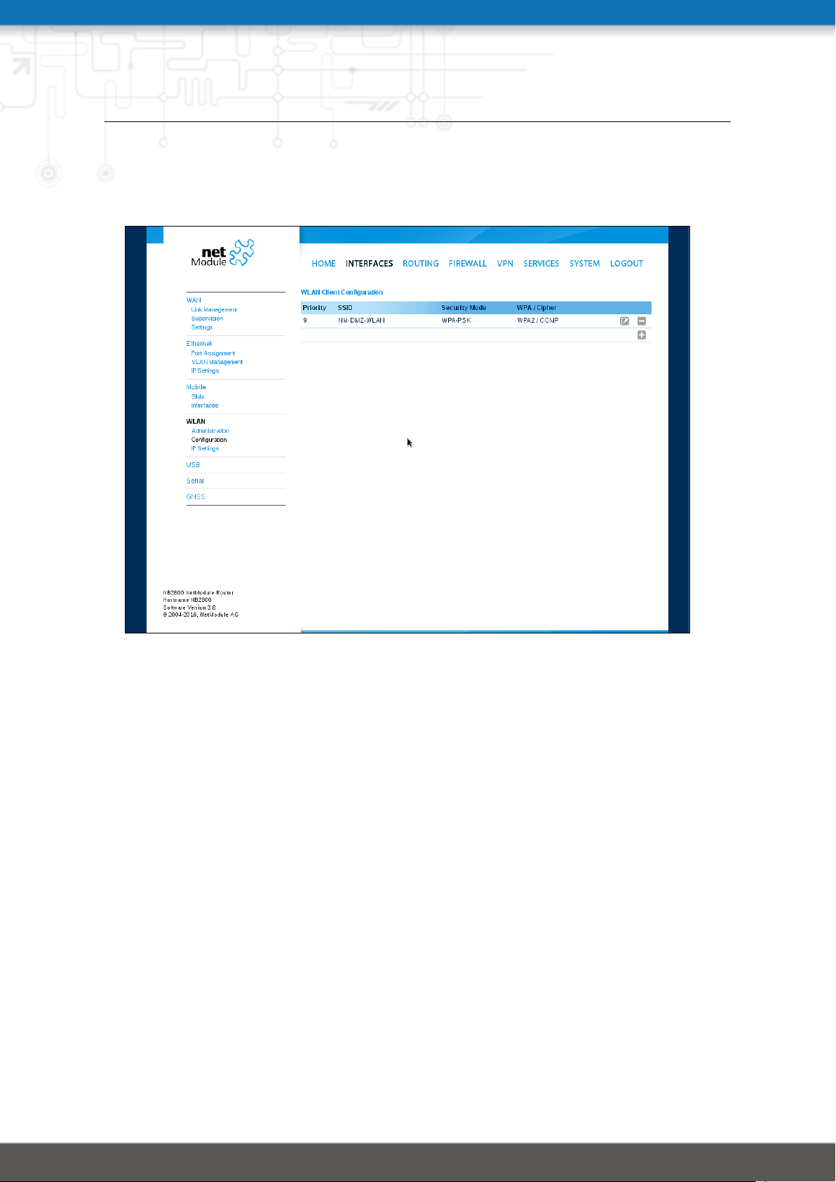
NB2800 User Manual 4.2
Running in access-point mode you can create up to 4 SSIDs with each running their own
network configuration. The networks can be individually bridged to a LAN interface or operate as dedicated interface in routing-mode.
Figure 5.13.: WLAN Configuration
59
Page 69

NB2800 User Manual 4.2
This section can be used to configure security-related settings.
Parameter WLAN Access-Point Configuration
SSID The network name (called SSID)
Security mode The desired security mode
WPA/WPA2 mixed mode WPA2 should be preferred over WPA1, running WPA/WPA2
mixed-mode offers both.
WPA cipher The WPA cipher to be used, the default is to run both (TKIP and
CCMP)
Identity The identity used for WPA-RADIUS and WPA-EAP-TLS
Passphrase The passphrase used for authentication with WPA-PSK, other-
wise the key passphrase for WPA-EAP-TLS
Force PMF Enables Protected Management Frames
Hide SSID Hides the SSID
Isolate clients Disables client-to-client communication
Accounting Sets accounting profile
The following security modes can be configured:
Parameter WLAN Security Modes
Off SSID is disabled
None No authentication, provides an open network
WEP WEP (is nowadays discouraged)
WPA-PSK WPA-PSK (TKIP, CCMP) aka WPA-Personal/Enterprise, provides
password-based authentication
WPA-RADIUS EAP-PEAP/MSCHAPv2, can be used to authenticate against
a remote RADIUS server which can be configured in chapter 5.8.2
WPA-TLS EAP-TLS, performs authentication using certificates which can
be configured in chapter 5.8.8
60
Page 70
NB2800 User Manual 4.2
Running in mesh point mode, it is possible to connect to one or more mesh points within
the mesh network at the same time. The system will automatically join the wireless network, connect to the other mesh partners with the same ID and sercurtiy credentials. The
authentication credentials have to be obtained by the operator of the mesh network.
Parameter WLAN Mesh-Point Configuration
MESHID The network name (called MESHID)
Security mode The desired security mode
enable gate announcements
To enable gate announcments for the mesh network
61
Page 71

NB2800 User Manual 4.2
The following security modes can be configured:
Parameter WLAN Mesh-Point Security Modes
Off MESHID is disabled
None No authentication, provides an open network
SAE SAE (Simultaneous Authentication of Equals) is a secure
password-based authentication and key establishment protocol
62
Page 72
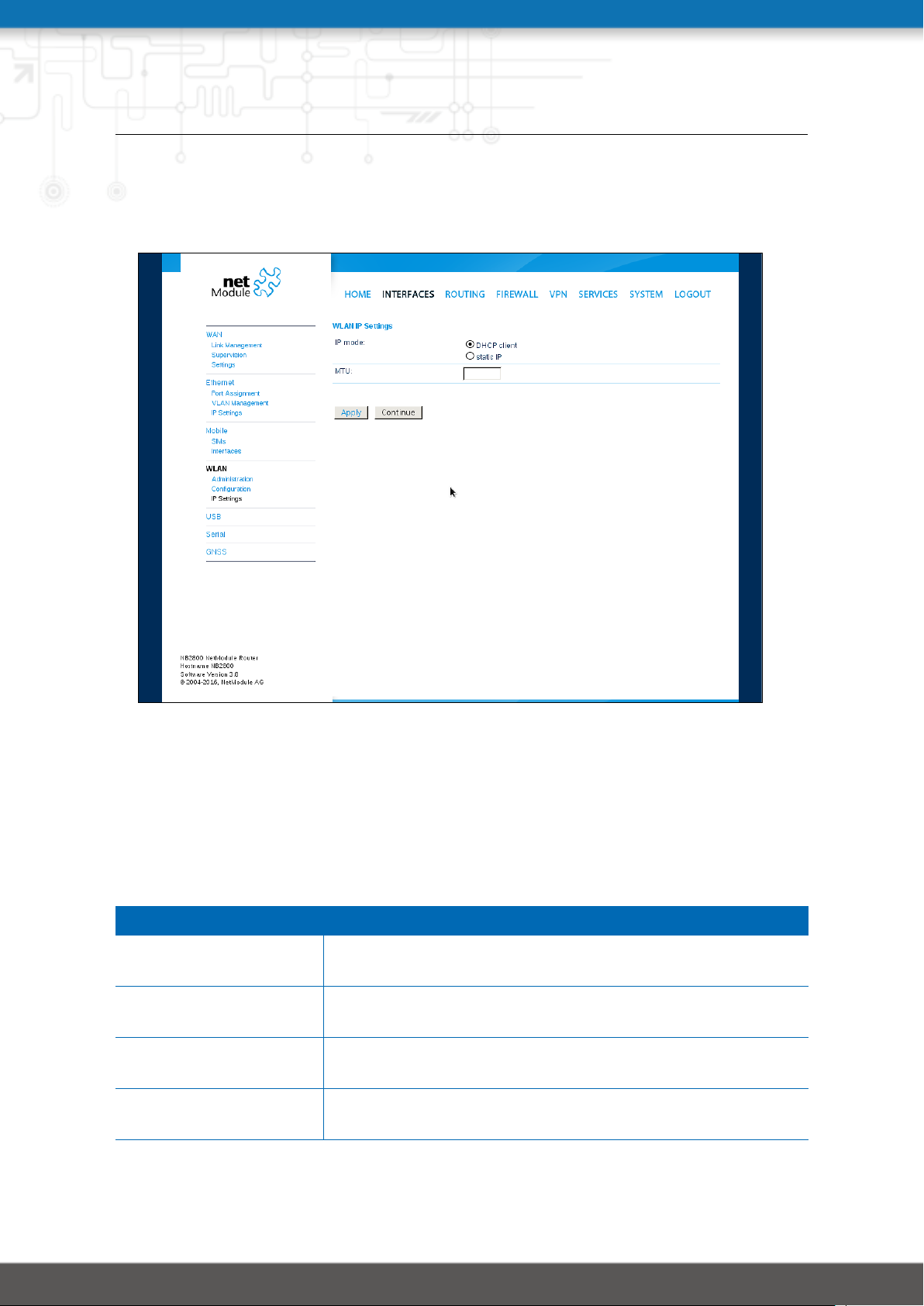
NB2800 User Manual 4.2
WLAN IP Settings
This section lets you configure the TCP/IP settings of your WLAN network. A client interface
can be run over DHCP or with a statically configured address and default gateway.
Figure 5.14.: WLAN IP Configuration
The access point networks can be bridged to any LAN interface for letting WLAN clients
and Ethernet hosts operate in the same subnet. However, for multiple SSIDs we strongly
recommend to set up separated interfaces in routing-mode in order to avoid unwanted
access and traffic between the interfaces. The corresponding DHCP server for each network
can be configured in afterwards as described in chapter 5.7.2.
Parameter WLAN IP Settings
Network mode Choose whether the interface shall be operated bridged or in
routing-mode
Bridge interface If bridged, the LAN interface to which the WLAN network
should be bridged
Bridging features If bridged, additional bridging features(e.g. IAPP, 4 address
frame) which can be en- or disabled
IP address / netmask In routing-mode, the IP address and netmask for this WLAN
network
63
Page 73

NB2800 User Manual 4.2
5.3.5. Software Bridges
Software bridges can be used to bridge layer-2 devices like OpenVPN TAP, GRE or WLAN
interfaces without the need for a physical LAN interface.
Bridge Settings
This page can be used to enable/disable software bridges.
It can be configured as follows:
Parameter Bridge Settings
Administrative status Enables or disables the bridge interface. If you need an inter-
face to the local system you need to define an IP address for
the local device.
IP Address IP address of the local interface (available only if "Enabled with
local interface" was selected
Netmask Netmask of the local interface (available only if "Enabled with
local interface" was selected
MTU Optional MTU size for the local interface (available only if "En-
abled with local interface" was selected
64
Page 74
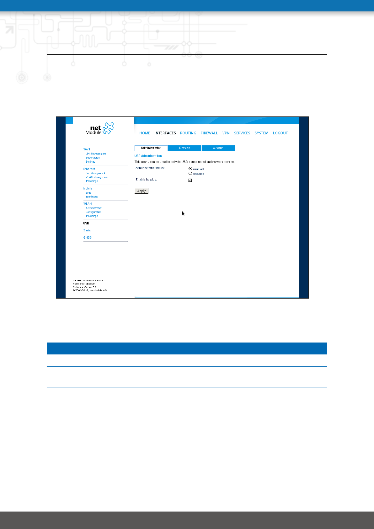
NB2800 User Manual 4.2
5.3.6. USB
NetModule routers ship with a standard USB host port which can be used to connect a
storage, network or serial USB device. Please contact our support in order to get a list of
supported devices.
Figure 5.15.: USB Administration
USB Administration
Parameter USB Administration
Administrative status Specifies whether devices shall be recognized
Enable hotplug Specifies whether device shall be recognized if plugged in dur-
ing runtime or only at bootup
Enable USB/IP device
server
If the USB/IP device server has been enabled you can discover the mounted USB devices
and attach them to the USB/IP server. Enabled devices can now be exported to a remote
host. You will need an additional driver on the client for which we provide Windows or Linux
drivers. Further installation instructions can be provided on demand.
Specifies if devices shall be exported over IP
65
Page 75
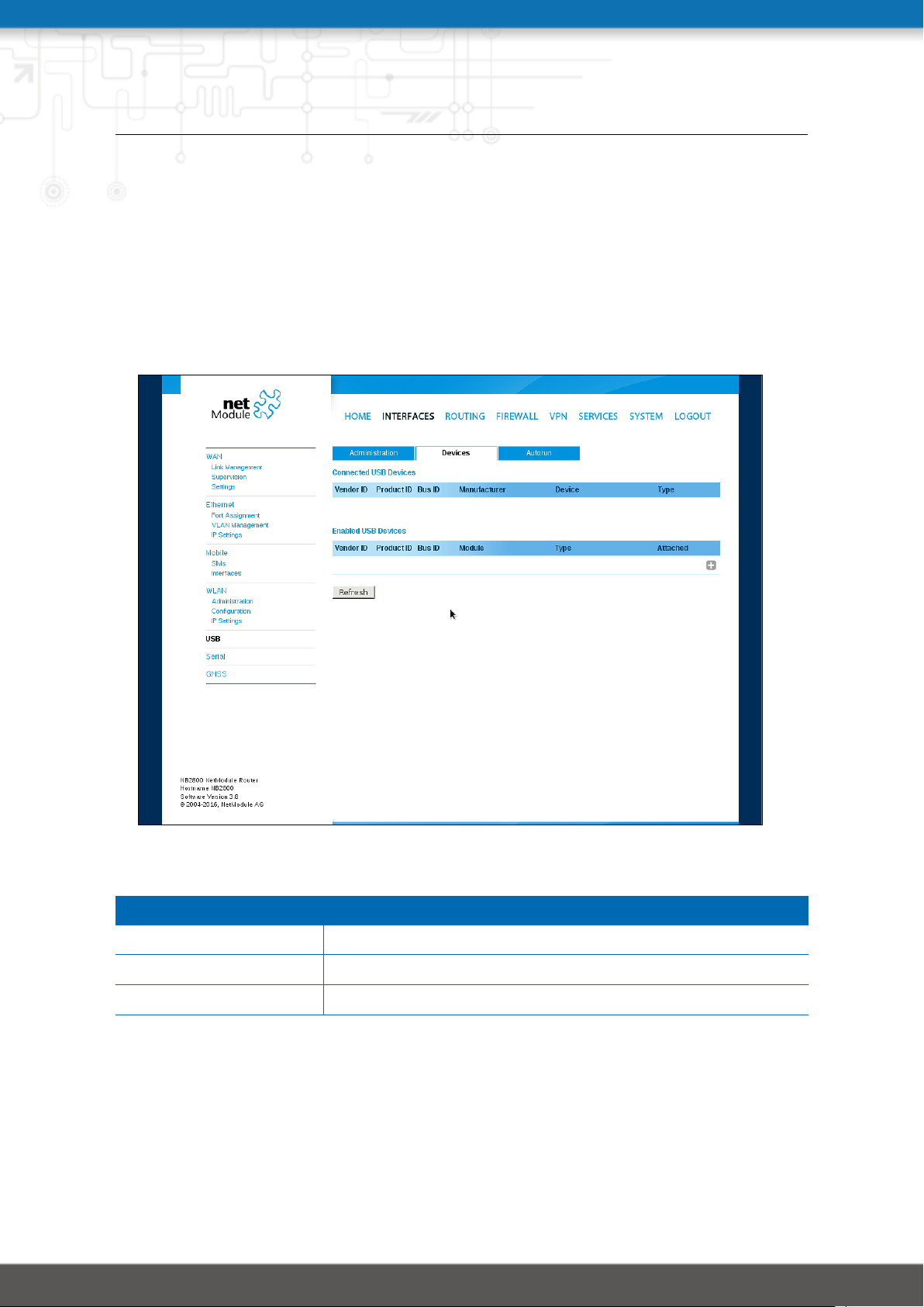
NB2800 User Manual 4.2
Please note that some USB devices behave latency-sensitive which may raise problems when
operating over a slow IP connection. Some devices may generally not work with the USB/IP
driver. Please contact our support in case of compatibility issues.
USB Devices
This page show the currently connected devices and it can be used to enable a specific device
based on its Vendor and Product ID. Only enabled devices will be recognized by the system
and raise additional ports and interfaces.
Figure 5.16.: USB Device Management
Parameter USB Devices
Vendor ID The USB Vendor ID of the device
Product ID The USB Product ID of the device
Module The USB module and type of driver to be applied for this device
Any ID must be specified in hexadecimal notation, wildcards are supported (e.g. AB[0-1][2-3]
or AB*) A USB network device will be referenced as LAN10.
66
Page 76

NB2800 User Manual 4.2
USB Autorun
This feature can be used to automatically launch a shell script or perform a software/config
update as soon as an USB storage stick has been plugged in. For authentication, a file called
autorun.key must exist in the root directory of a FAT16/32 formatted stick. It can be downloaded from that page and holds the SHA256 hash key of the admin password. The file can
hold multiple hashes which will be processed line-by-line during authentication which can
be used for setting up more systems with different admin passwords.
For new devices with an empty password the hash key
e3b0c44298fc1c149afbf4c8996fb92427ae41e4649b934ca495991b7852b855
can be used.
The hash keys can be generated by running the command echo -n "<admin-password>" |
sha256sum on a Linux system or an Internet hash key generator (search for "sha-256 hash
calculator").
Once authentication has succeeded, the system scans for other files in the root directory
which can perform the following actions:
1. For running a script: autorun.sh
2. For a configuration update: cfg-<SERIALNO>.zip (e.g. cfg-00112B000815.zip), or if
not available cfg.zip
3. For a software update: sw-update.img
67
Page 77
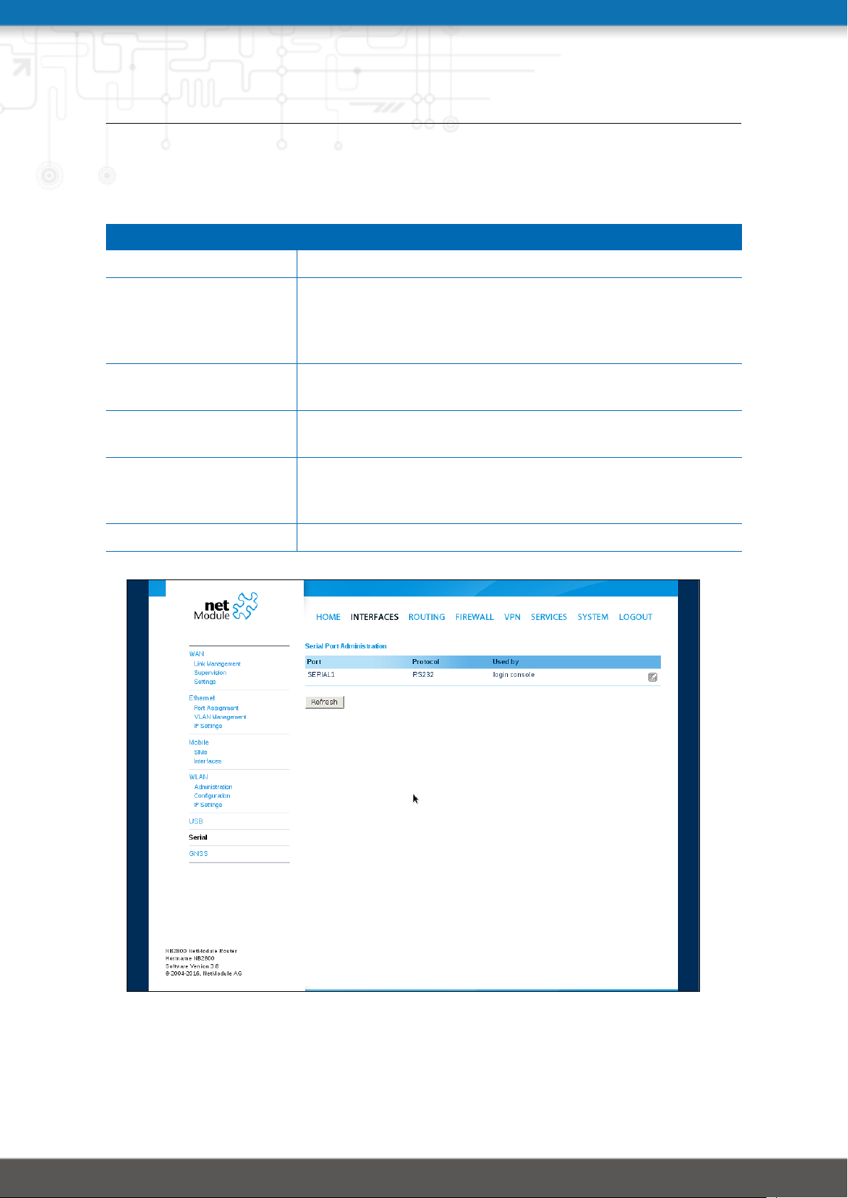
NB2800 User Manual 4.2
5.3.7. Serial Port
This page can be used to manage your serial ports. A serial port can be used by:
Parameter Serial Port Usage
none The serial port is not used
login console The serial port is used to open a console which can be accessed
with a serial terminal client from the other side. It will provide
helpful bootup and kernel messages and spawns a login shell,
so that users can login to the system.
device server The serial port will be exposed over a TCP/IP port and can be
used to implement a Serial/IP gateway.
modem bridge Bridges the Serial Interface to the Modem TTY of an inter-
grated WWAN Modem.
modem emulator Emulates a classical AT command driven modem on the se-
rial interface. See http://wiki.netmodule.com/app-notes/
hayes-modem-at-simulator for detailed information.
SDK The serial port will be reserved for SDK scripts.
Figure 5.17.: Serial Port Administration
68
Page 78
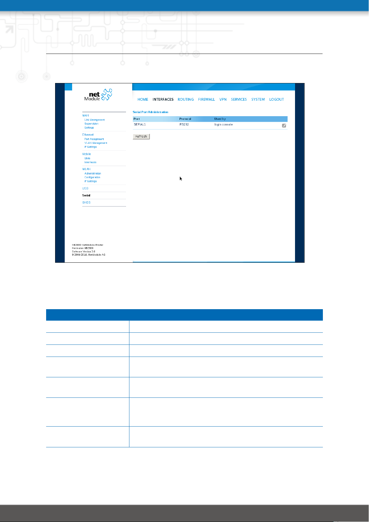
NB2800 User Manual 4.2
Running a device server, the following settings can be applied:
Figure 5.18.: Serial Port Settings
Parameter Serial Settings
Physical protocol Selects the desired physical protocol on the serial port
Baud rate Specifies the baud rate run on the serial port
Data bits Specifies the number of data bits contained in each frame
Parity Specifies the parity used for every frame that is transmitted or
received
Stop bits Specifies the number of stop bits used to indicate the end of a
frame
Software flow control Defines the software flow control for the serial port, XOFF will
send a stop, XON a start character to the other end to control
the rate of any incoming data
Hardware flow control You may enable RTS/CTS hardware flow control, so that the
RTS and CTS lines are used to control the flow of data
69
Page 79

NB2800 User Manual 4.2
Parameter Serial Settings
Protocol on TCP/IP You may choose the IP protocols Telnet or TCP raw for the
device server
Port The TCP port for the device server
Timeout The timeout until a client is declared as disconnected
Parameter Server Settings
Protocol on IP port Selects the desired IP protocol (TCP or Telnet)
Port Specifies the TCP port on which the server will be available
Timeout The time in seconds before the port will be disconnected if
there is no activity on it. A zero value disables this function.
Allow remote control Allow remote control (ala RFC 2217) of the serial port
Show banner Show a banner when clients connect
Stop bits Specifies the number of stop bits used to indicate the end of a
frame
Allow clients from Specifies which clients are allowed to connect to the server
Please note that the device server does not provide authentication or encryption and clients
will be able connect from everywhere. Please consider to restrict access to a limited network/host or block packets by using the firewall.
70
Page 80
NB2800 User Manual 4.2
When running the serial port as AT modem emulator the following settings can be applied:
Parameter Serial Port Settings
Physical protocol Selects the desired physical protocol on the serial port
Baud rate Specifies the baud rate run on the serial port
Hardware flow control You may enable RTS/CTS hardware flow control, so that the
RTS and CTS lines are used to control the flow of data
Parameter Incoming connections via Telnet
Port The TCP port for the device server
Parameter Phonebook Entries
Number Phone number that will get an alias
IP address IP address the number will become
Port Port value for the IP address
71
Page 81
NB2800 User Manual 4.2
5.3.8. Audio
Audio Administration
This page can be used to pre-configure the audio module. It can be later used for the voice
gateway.
It can be configured as follows:
Parameter Audio Settings
Volume level Default volume level for line-out
Audio Testing
This page can be used to play or record an audio sample.
72
Page 82

NB2800 User Manual 4.2
5.3.9. GNSS
Administration
The GNSS page lets you enable or disable the GNSS modules present in the system and
can be used to configure the daemon that can be used to share access to receivers without
contention or loss of data and to respond to queries with a format that is substantially easier
to parse than the NMEA 0183 emitted directly by the GNSS device.
We are currently running the Berlios GPS daemon (version 3.15), supporting the new JSON
format. Please navigate to http://www.catb.org/gpsd/ for getting more information about
how to connect any clients to the daemon remotely. The position values can also be queried
by the CLI and used in SDK scripts.
Parameter GNSS Module Configuration
Administrative status Enable or disable the GNSS module
Operation mode The mode of operation, either standalone or assisted (for A-
GPS)
Antenna type The type of the connected GPS antenna, either passive or ac-
tively 3 volt powered
Accuracy The desired accuracy in meters
Fix frame interval The amount of time to wait between fix attempts
Parameter GNSS Server Configuration
Server port The TCP port on which the daemon is listening for incoming
connections
Allow clients from Specifies where clients can connect from, can be either
everywhere or from a specific network
Clients start mode Specifies how data transferal is accomplished when a client
connects. You can specify on request which typically requires
an R to be sent. Data will be sent instantly in case of raw mode
which will provide NMEA frames or super-raw which includes
the original data of the GPS receiver. If the client supports the
JSON format (i.e. newer libgps is used) the json mode can be
specified.
Please consider to restrict access to the server port, either by a specifying a dedicated client
network or by using a firewall rule.
73
Page 83

NB2800 User Manual 4.2
Position
This pages provides further information about the satellites in view and values derived from
them:
Parameter GNSS Information
Latitude The geographic coordinate specifying the north-south position
Longitude The geographic coordinate specifying the east-west position
Altitude The height above sea level of the current location
Satellites in view The number of satellites in view as stated in GPGSV frames
Speed The horizontal and vertical speed in meter per second as
stated in GPRMC frames
Satellites used The number of satellites used for calculating the position as
stated in GPGGA frames
Dilution of precision The dilution of precision as stated in GPGSA frames
Furtheron, each satellite also comes with the following details:
Parameter GNSS Satellite Information
PRN The PRN code of the satelitte (also referred as satellite ID) as
stated in GPGSA frames
Elevation The elevation (up-down angle between the dish pointing direc-
tion) in degrees as stated in GPGSV frames
Azimuth The azimuth (rotation around the vertical axis) in degrees as
stated in GPGSV frames
SNR The SNR (Signal to Noise Ratio), often referred as signal
strength
Please note that the values are shown as calculated by the daemon, their accuracy might be
suggestive.
Supervision
Parameter GNSS Supervision
Administrative status Enable or disable GNSS supervision
Mode Specifies whether to monitor the NMEA stream or GPS fixes
Max. downtime The period of time without valid NMEA stream or GPS fix after
which an emergency action shall be taken
74
Page 84

NB2800 User Manual 4.2
Parameter GNSS Supervision
Emergency action The corresponding emergency action. You can either let just
restart the server, which will also re-initialize the GPS function
on the module, or reset the module in severe cases. Please
note that this may have effects on any running WWAN/SMS
services.
75
Page 85
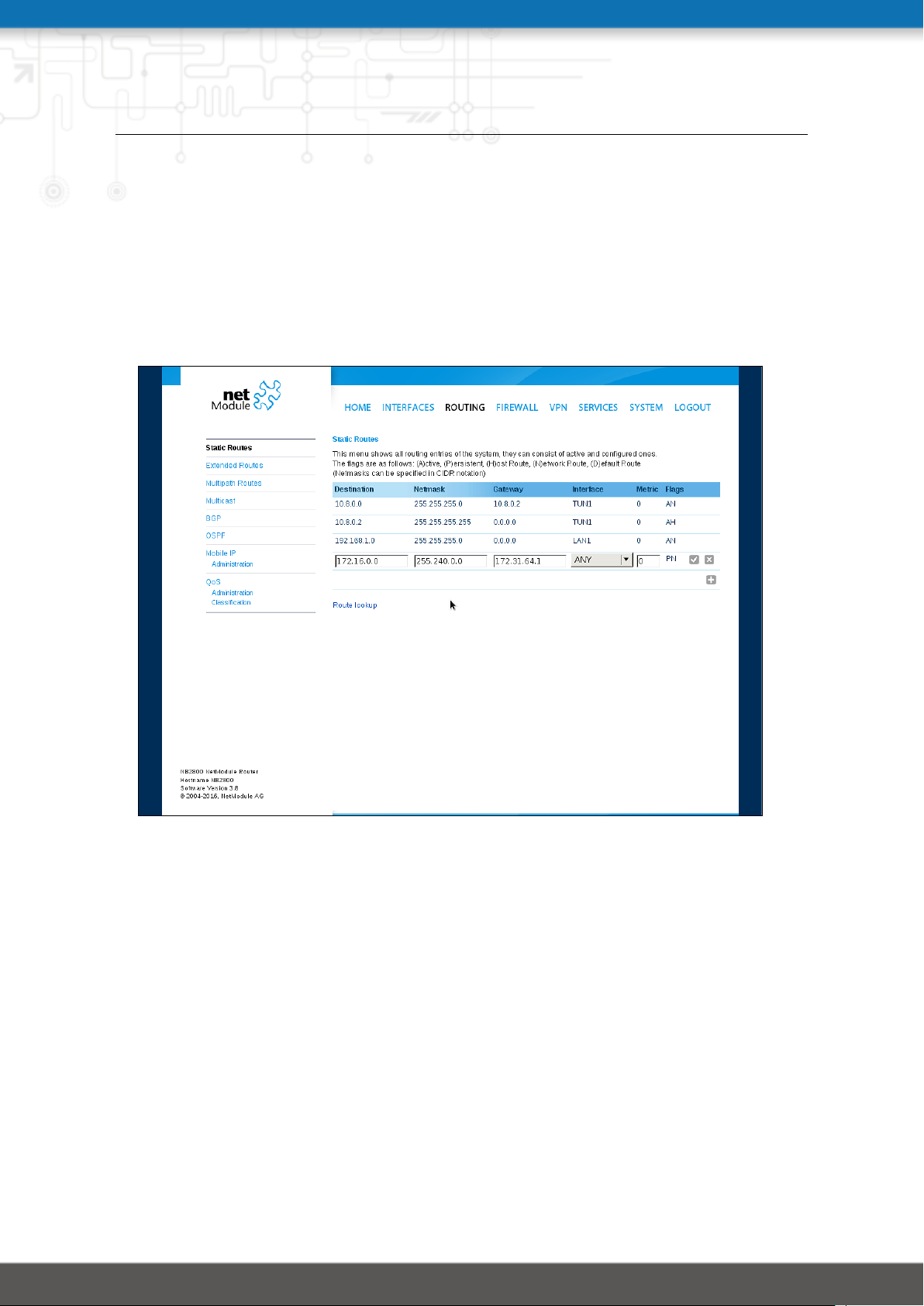
NB2800 User Manual 4.2
5.4. ROUTING
5.4.1. Static Routes
This menu shows all routing entries of the system. They are typically formed by an address/netmask couple (represented in IPv4 dotted decimal notation) which specify the destination of a packet. The packets can be directed to either a gateway or an interface or both.
If interface is set to ANY, the system will choose the route interface automatically, depending
on the best matching network configured for an interface.
Figure 5.19.: Static Routing
In general, host routes precede network routes and network routes precede default routes.
Additionally, a metric can be used to determine the priority of a route, a packet will go in the
direction with the lowest metric in case a destination matches multiple routes.
Netmasks can be specified in CIDR notation (i.e. /24 expands to 255.255.255.0).
76
Page 86

NB2800 User Manual 4.2
Parameter Static Route Configuration
Destination The destination address of a packet
Netmask The subnet mask which forms, in combination with the des-
tination, the network to be addressed. A single host can be
specified by a netmask of 255.255.255.255, a default route corresponds to 0.0.0.0.
Gateway The next hop which operates as gateway for this network (can
be omitted on peer-to-peer links)
Interface The network interface on which a packet will be transmitted in
order to reach the gateway or network behind it
Metric The routing metric of the interface (default 0), higher metrics
have the effect of making a route less favorable
Flags (A)ctive, (P)ersistent, (H)ost Route, (N)etwork Route, (D)efault
Route
The flags obtain the following meanings:
Flag Description
A The route is considered active, it might be inactive if the interface for this route
is not yet up.
P The route is persistent, which means it is a configured route, otherwise it corre-
sponds to an interface route.
H The route is a host route, typically the netmask is set to 255.255.255.255.
N The route is a network route, consisting of an address and netmask which forms
the subnet to be addressed.
D The route is a default route, address and netmask are set to 0.0.0.0, thus match-
ing any packet.
Table 5.44.: Static Route Flags
77
Page 87
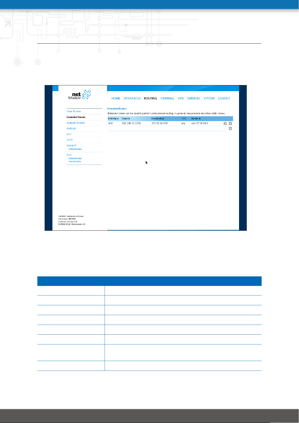
NB2800 User Manual 4.2
5.4.2. Extended Routing
Extended routes can be used to perform policy-based routing, they generally precede static
routes.
Figure 5.20.: Extended Routing
In contrast to statis routes, extended routes can be made up, not only of a destination
address/netmask, but also a source address/netmask, incoming interface and the type of
service (TOS) of packets.
Parameter Extended Route Configuration
Source address The source address of a packet
Source netmask The source address of a packet
Destination address The destination address of a packet
Destination netmask The destination address of a packet
Incoming interface The interface on which the packet enters the system
Type of service The TOS value within the header of the packet
Route to Specifies the target interface or gateway to where the packet
should get routed to
discard if down Discard packets if the specified interface is down
78
Page 88
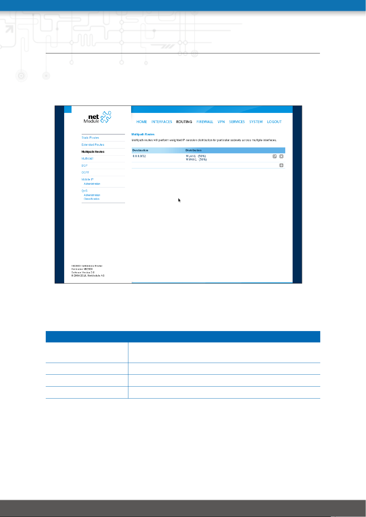
NB2800 User Manual 4.2
5.4.3. Multipath Routes
Multipath routes will perform weighted IP-session distribution for particular subnets across
multiple interfaces.
Figure 5.21.: Multipath Routes
At least two interfaces have to be defined to establish multipath routing. Additional interfaces can be added by pressing the plus sign.
Parameter Add Multipath Routes
Target network/netmask Defines the target network for which multipath routing shall
be applied
Interface Selects the interface for one path
Weight Weight of the interface in relation to the others
NextHop Overrides the default gateway of this interface
79
Page 89

NB2800 User Manual 4.2
5.4.4. Mobile IP
Mobile IP (MIP) can be used to enable seamless switching between different kinds of WAN
links (e.g. WWAN/WLAN). The mobile node hereby remains reachable via the same IP address (home address) at any time, independently of the WAN link being used. Effectively,
any WAN link switch causes very small outages during switchover while keeping all IP connections alive.
Moreover, NetModule routers also support NAT-Traversal for mobile nodes running behind
a firewall (performing NAT), which makes mobile nodes even there accessible from a central
office via their home address, and thus, bypassing any complicated VPN setups.
The home agent accomplishes this by establishing a tunnel (similar to a VPN tunnel) between itself and the mobile node. WAN link switching works by telling the home agent that
the WAN IP address (called the care-of address in MIP terms) of the mobile node has
changed. The home agent will then encapsulate packets destined to a mobile node’s home
address into a tunnel packet containing the current care-of address of the mobile node as
its destination address.
To prevent problems with firewalls and private IP addressing, the MIP implementation always employs reverse tunneling, which means that all traffic sent by a mobile node is relayed via the tunnel to the home agent instead of directly being conveyed to the final destination. This fact also empowers MIP to be used as a lightweight VPN replacement (without
payload secrecy).
The MIP implementation supports RFCs 3344, 5177, 3024 and 3519. For applications requiring vast numbers of mobile nodes, interoperability with the Cisco 2900 Series home agent
implementation has been verified. However, since NetModule routers implement a mobile
node as well as a home agent, a MIP network with up to 10 mobile nodes can be implemented without requiring expensive third party routers.
If MIP is run as a mobile node, the following settings can be configured:
Parameter Mobile IP Configuration
Primary home agent address
Secondary home agent
address
Home address The permanent home address of the mobile node which can
The address of the primary home agent
The address of the secondary home agent. The mobile node
will try to register with this home agent, if the primary home
agent is not reachable.
be used to reach the mobile router at any time
80
Page 90

NB2800 User Manual 4.2
Parameter Mobile IP Configuration
SPI The Security Parameter Index (SPI) identifying the security
context for the mobile IP tunnel between the mobile node and
the home agent. This is used to distinguish mobile nodes from
each other. Therefore each mobile node needs to be assigned
a unique SPI. This is a 32-bit hexadecimal value.
Authentication type The used authentication algorithm. This can be prefix-suffix-
md5 (default for MIP) or hmac-md5.
Shared secret The shared secret used for authentication of the mobile node
at the home agent. This can be either a 128-bit hexadecimal
value or a random length ASCII string.
Life time The lifetime of security associations in seconds
UDP encapsulation Specifies whether UDP encapsulation shall be used or not. To
allow NAT traversal, UDP encapsulation must be enabled.
Mobile network address Optionally specifies a subnet which should be routed to the
mobile node. This information is forwarded via Network Mobility (NEMO) extensions to the home agent. The home agent
can then automatically add IP routes to the subnet via the
mobile node. Note that this feature is not supported by all
third party home agent implementations.
Mobile network mask The network mask for the optional routed network
81
Page 91
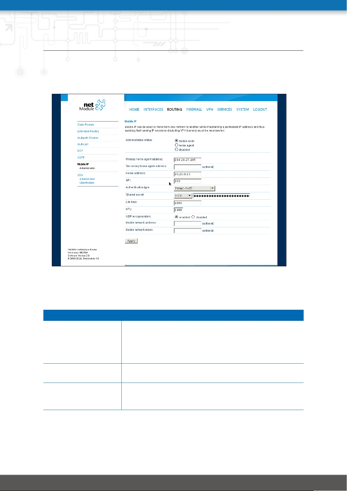
NB2800 User Manual 4.2
If MIP is run as a home agent, you will have to set up a home address and network mask for
the home agent first. Then you will need to add the configuration for all mobile nodes which
is made up of the following settings:
Figure 5.22.: Mobile IP
Parameter Mobile IP Node Configuration
SPI The Security Parameter Index (SPI) identifying the security
context for the tunnel between the mobile node and the home
agent. This is used to distinguish mobile nodes from each
other. Therefore each mobile node needs to be assigned a
unique SPI. This is a 32-bit hexadecimal value.
Authentication type The used authentication algorithm. This can be prefix-suffix-
md5 (default for mobile IP) or hmac-md5.
Shared secret The shared secret used for authentication of the mobile node
at the home agent. This can be either a 128-bit hexadecimal
value or a random length ASCII string.
82
Page 92

NB2800 User Manual 4.2
5.4.5. Quality Of Service
NetModule routers are able to prioritize and shape certain kinds of IP traffic. This is currently
limited on egress, which means that only outgoing traffic can be stipulated.
The current QoS solution is using Stochastic Fairness Queueing (SFQ) classes in combination
with Hierarchy Token Bucket (HTB) qdiscs. Its principle of operation can be summarized as
ceiling the max. throughput per link and shaping traffic by reflecting the specified queue
priorities. In general, the lowest priority number of a queue gets most out of the available
bandwidth.
In case of demands for other class or qdisc algorithms please contact our support team in
order to evaluate the best approach for your application.
QoS Administration
The administration page can be used to enable and disable QoS.
QoS Classification
The classification section can be used to define the WAN interfaces on which QoS should be
active.
Parameter QoS Interface Parameters
Interface The WAN interface on which QoS should be active
Bandwidth congestion The bandwidth congestion method. In case of auto the system
will try to apply limits in a best-effort way. However, it is suggested to set fixed bandwidth limits as they also offer a way of
tuning the QoS behaviour.
Downstream bandwidth The available bandwidth for incoming traffic
Upstream bandwidth The available bandwidth for outgoing traffic
IP to ping (primary) An IP, which answers ICMP echo requests to determine the
bandwidth of the link
IP to ping (secondary) An IP, which answers ICMP echo requests to determine the
bandwidth of the link
When defining limits, you should consider bandwidth limits which are at least possible as
most shaping and queues algorithms will not work correctly if the specified limits cannot
be achieved. In particular, any WWAN interfaces operating in a mobile environment are
suffering variable bandwidths, thus rather lower values should be used.
83
Page 93

NB2800 User Manual 4.2
In case an interface has been activated, the system will automatically create the following
queues:
Parameter QoS Default Queues
high A high priority queue which may hold any latency-critical ser-
vices (such as VoIP)
default A default queue which will handle all other services
low A low priority queue which may hold less-critical services for
which shaping is intended
Each queue can be configured as follows:
Parameter QoS Queue Parameters
Name The name of the QoS queue
Priority A numerical priority for the queue, lower values indicate
higher priorities
Bandwidth The maximum possible bandwidth for this queue in case the
total bandwidth of all queues exceeds the set upstream bandwidth of "QoS Interface Parameters"
Set TOS The TOS/DiffServ value to set on matching packets
You can now configure and assign any services to each queue. The following parameters
apply:
Parameter QoS Service Parameters
Interface The QoS interface of the queue
Queue The QoS queue to which this service shall be assigned
Source Specifies a network address and netmask used to match the
source address of packets
Destination Specifies a network address and netmask used to match the
destination (target) address of packets
Protocol Specifies the protocol for packets to be matched
Source Port Specifies the source port for packets to be matched
Destination Port Specifies the destination port for packets to be matched
Type of Service Specifies the TOS/DiffServ for packets to be matched
84
Page 94

NB2800 User Manual 4.2
5.4.6. Multicast
Multicast routing (MCR) can be configured and managed by a daemon. Only one MCR daemon can be used at a time.
NetModule routers ship with two different MCR daemons to select from depending on your
dependencies:
Parameter Administrative Status
IGMP proxy Forwarding of multicast messages that are dynamically de-
tected on a given interface to another interface
static routes List of MCR rules to forward messages of dedicated source and
group from a given interface to another
disabled Disable routing of multicast messages
IGMP proxy
IGMP proxy which is able to maintain multicast groups on a particular interface and distribute incoming multicast packets towards the downstream interfaces on which hosts have
joined the groups.
Parameter Multicast Routing Settings
Administrative status Specifies whether multicast routing is active
Incoming interface The upstream interface on which multicast groups are joined
and on which multicast packets come in
Distribute to Specifies the downstream interfaces to which multicast pack-
ets will be forwarded
Static Routes
Routes multicast messages in different directions depending on their origin and group based
on a given set of MCR rules:
Parameter Static Multicast Route
Group IP address of MCR group
Source Source-IP of the packets
Incoming interface Interface to listen on for messages of given group and source
Outgoing interface Interface to forward the messages to
85
Page 95

NB2800 User Manual 4.2
5.4.7. OSPF
The OSPF tab allows the NetModule router to be added to a network of OSPF routers.
Parameter OSPF General Settings
OSPF status Specifies whether the OSPF routing protocol is active
Redistribute connected
routes
Redistribute local routes Redistribute routes from the NetModule router’s own routing
Redistribute BGP routes Redistribute routes learned via the BGP routing protocol
Redistribute default
route
Disable BGP when VRRP
slave
The interfaces tab is used to define OSPF specific settings for the IP interfaces of the router.
If no settings are defined for a specific interface, default settings will be used.
Parameter OSPF Interfaces
Interface The name of the interface for which settings shall be defined
Authentication The authentication protocol to be used on the interface to au-
Key The key to be used for authentication
Redistribute routes to networks which are directly connected
to the NetModule router
table
Redistribute the routers default route
Disables the OSPF protocol when the router is set to slave
mode by the VRRP redundancy protocol
thenticate OSPF packets
Key ID The ID of the key to be used for authentication (1-255)
Cost The cost for sending packets via this interface. If not specified
or set to 0 OSPF defaults are used.
Passive Do not send out OSPF packets on this interface
The networks tab defines the IP networks to be handled in OSPF as well as to which routing
area they belong.
Parameter OSPF Networks
Prefix Prefix of the network
Prefix length Length of the prefix
Area Routing area to which this interface belongs (0-65535, 0 means
backbone)
86
Page 96

NB2800 User Manual 4.2
5.4.8. BGP
The BGP tab allows to set up peerings of the NetModule router with other Border Gateway
Protocol enabled routers.
Parameter BGP General Settings
BGP status Specifies whether the BGP routing protocol is active
AS number The number of the autonomous system to which the NetMod-
ule router belongs (1-4294967295)
Redistribute connected
routes
Redistribute local routes Redistribute routes from the NetModule router’s own routing
Redistribute OSPF routes Redistribute routes learned via the OSPF routing protocol
Disable BGP when VRRP
slave
The neighbors tab is used to configure all the BGP routers to peer with.
Parameter BGP Neighbors
IP address IP address of the peer router
As number Autonomous system number of the peer router (1-
Password Password for authentication with the peer router. If left blank
Multihop Allow multiple hops between this router and the peer router
Redistribute routes to networks which are directly connected
to the NetModule router
table
Disables the BGP protocol when the router is set to slave mode
by the VRRP redundancy protocol
4294967295)
authentication is disabled.
instead of requiring the peer to be directly connected.
The Networks tab allows to add IP network prefixes that shall be distributed via BGP in
addition to the networks that are redistributed from other sources as defined on the general
tab.
Parameter BGP Networks
Prefix Prefix of the network to be distributed
Prefix length Length of the prefix to be distributed
87
Page 97
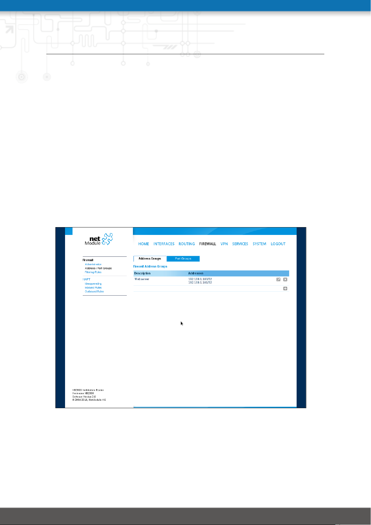
NB2800 User Manual 4.2
5.5. FIREWALL
5.5.1. Administration
NetModule routers use Linux’s netfilter/iptables firewall framework
(see http://www.netfilter.org for more information) which supports stateful inspection,
that is, granting the same permissions for inherited connections within an IP session (e.g.
FTP which builds up a control and data connection).
The administration page can be used to enable and disable firewalling. When turning it on, a
shortcut can be used to generate a predefined set of rules which allow administration (over
HTTP, HTTPS, SSH or TELNET) by default but block any other packets coming from the WAN
interface.
5.5.2. Adress/Port Groups
This menu can be used to form address or port groups which can be later used for firewall
rules in order to reduce the number of rules. If address or port groups have been referenced, packets will match if one of the configured entities apply to the packet.
Figure 5.23.: Firewall Groups
88
Page 98
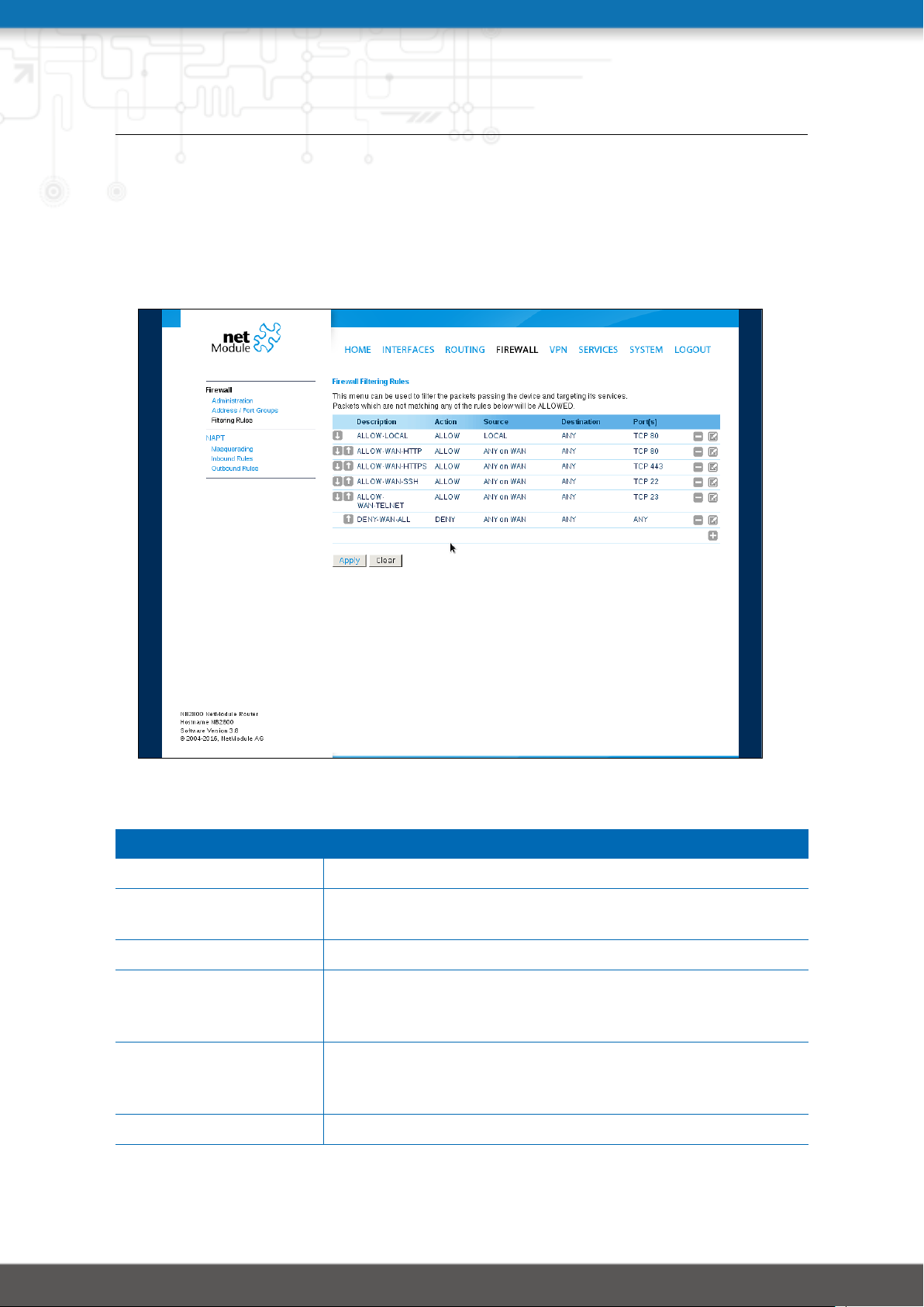
NB2800 User Manual 4.2
5.5.3. Rules
In general, the firewall is set up of a range of rules which control each packet’s permission
to pass the router. Please note that the rules are processed by order, that means traversing
the list from top to bottom until a matching rule is found. Packets which are not matching
any of the rules configured will be ALLOWED.
Figure 5.24.: Firewall Rules
Parameter Firewall Rule Configuration
Description A meaningful description about the purpose of this rule
Action Specifies whether the packets of this rule should be allowed or
denied
log matches Throw a syslog message if rule matches
Source The source address of matching packets, can be any or speci-
fied by address/network. Selecting on source MAC addreses is
possible as well.
Destination The destination address of matching packets, can be any, local
(addressed to the system itself) or specified by address/network
Incoming interface The interface on which matching packets are received
89
Page 99

NB2800 User Manual 4.2
Parameter Firewall Rule Configuration
Protocol The used IP protocol of matching packets (UDP, TCP or ICMP)
Destination port(s) The destination port of matching packets, which can be speci-
fied by a single port or a range of ports (only UDP/TCP).
The statistics page can be used to figure out if rules have matched any packets and provides
a convenient way to debug your firewall setup.
90
Page 100
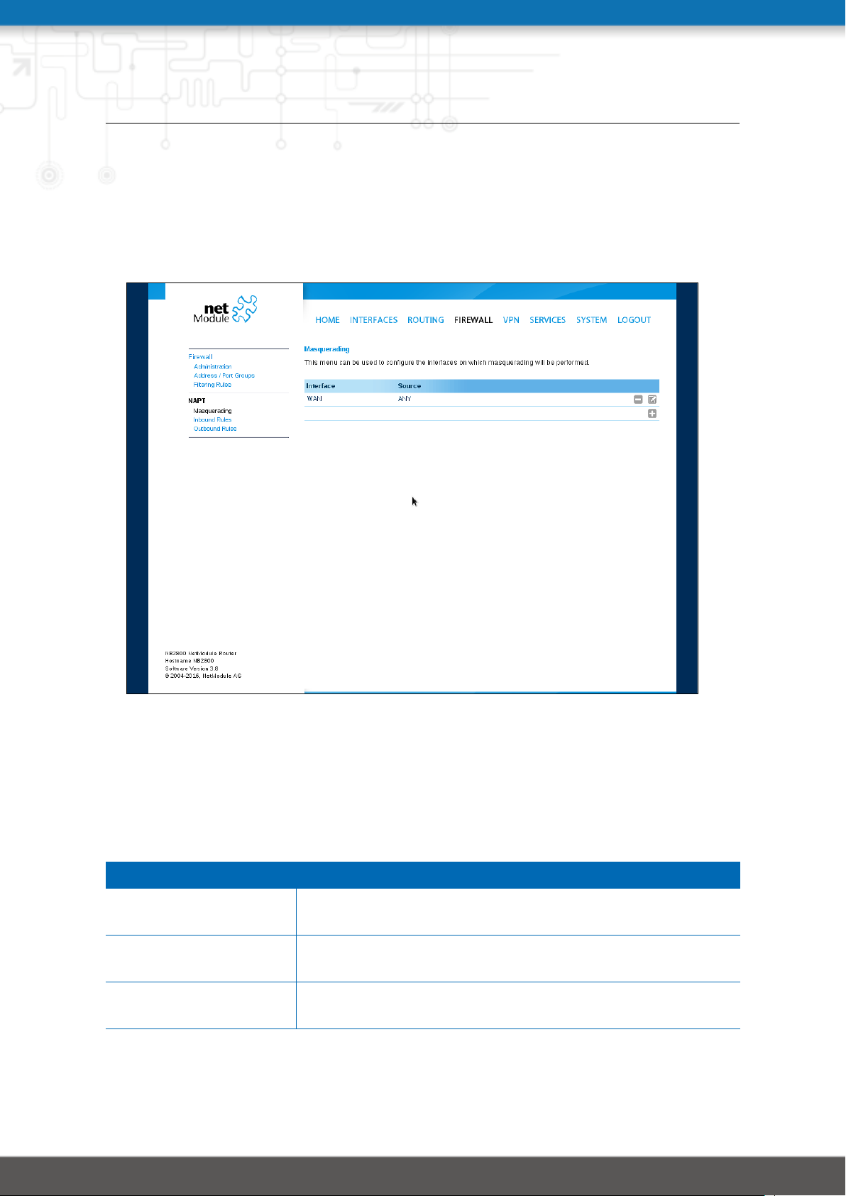
NB2800 User Manual 4.2
5.5.4. NAPT
This page can be used to configure Network Address and Port Translation (NAPT) for packets
traversing the system. NAPT hereby modifies IP addresses or/and TCP/UDP ports in matching IP packets. By tracking those connections, it will also automatically adjust the returning
packets of an IP session.
Figure 5.25.: Masquerading
The administration page lets you specify the interfaces on which masquerading will be performed. NAT will hereby use the address of the selected interface and choose a random
source port for outgoing connections and thus enables communication between hosts from
a private local area network towards hosts on the public network.
Parameter Masqerading Rules
Interface The outgoing interface on which connections will be masquer-
aded
Source address The source address or network from which matching packets
are masqueraded
Source netmask The source netmask of the network from which matching pack-
ets are masqueraded
91
 Loading...