

Page 1

NetModule Router NB2700
User Manual
Manual Version 1.0
NetModule AG, Switzerland
November 28, 2012
WWW.INFOPULSAS.LT / [email protected]
Page 2

Contents
1 Welcome to NetModule 8
2 Conformity 9
2.1 Safety Instructions . . . . . . . . . . . . . . . . . . . . . . . . . . . . . . 9
2.2 Declaration of Conformity . . . . . . . . . . . . . . . . . . . . . . . . . . 10
2.3 Waste Disposal . . . . . . . . . . . . . . . . . . . . . . . . . . . . . . . . 10
2.4 National Restrictions . . . . . . . . . . . . . . . . . . . . . . . . . . . . . 10
2.4.1 France . . . . . . . . . . . . . . . . . . . . . . . . . . . . . . . . . 10
2.4.2 Italy . . . . . . . . . . . . . . . . . . . . . . . . . . . . . . . . . . 11
2.4.3 Latvia . . . . . . . . . . . . . . . . . . . . . . . . . . . . . . . . . 11
2.4.4 Luxembourg . . . . . . . . . . . . . . . . . . . . . . . . . . . . . . 11
2.4.5 Norway . . . . . . . . . . . . . . . . . . . . . . . . . . . . . . . . 11
2.4.6 Russian Federation . . . . . . . . . . . . . . . . . . . . . . . . . . 11
2.4.7 Turkey . . . . . . . . . . . . . . . . . . . . . . . . . . . . . . . . . 12
3 Specifications 13
3.1 Operating Elements . . . . . . . . . . . . . . . . . . . . . . . . . . . . . . 13
3.2 Interfaces . . . . . . . . . . . . . . . . . . . . . . . . . . . . . . . . . . . 15
3.2.1 Overview . . . . . . . . . . . . . . . . . . . . . . . . . . . . . . . 15
3.2.2 USB 2.0 Host Port . . . . . . . . . . . . . . . . . . . . . . . . . . 16
3.2.3 RJ45 Ethernet Connectors . . . . . . . . . . . . . . . . . . . . . . 16
3.2.4 13 Pin Terminal Block . . . . . . . . . . . . . . . . . . . . . . . . 17
4 Installation 20
4.1 Environmental Conditions . . . . . . . . . . . . . . . . . . . . . . . . . . 20
4.2 Installation of the Router . . . . . . . . . . . . . . . . . . . . . . . . . . 20
4.3 Installation of SIM Cards . . . . . . . . . . . . . . . . . . . . . . . . . . . 20
4.4 Installation of the GSM/UMTS Antenna . . . . . . . . . . . . . . . . . . 21
4.5 Installation of the WLAN Antennas . . . . . . . . . . . . . . . . . . . . . 21
4.6 Installation of the Local Area Network . . . . . . . . . . . . . . . . . . . 21
4.7 Installation of the Power Supply . . . . . . . . . . . . . . . . . . . . . . . 22
5 Configuration 23
2
Page 3

NB2700 User Manual
5.1 First Steps . . . . . . . . . . . . . . . . . . . . . . . . . . . . . . . . . . . 23
5.1.1 Initial Access . . . . . . . . . . . . . . . . . . . . . . . . . . . . . 23
5.1.2 Recovery . . . . . . . . . . . . . . . . . . . . . . . . . . . . . . . . 24
5.2 HOME . . . . . . . . . . . . . . . . . . . . . . . . . . . . . . . . . . . . . 25
5.3 INTERFACES . . . . . . . . . . . . . . . . . . . . . . . . . . . . . . . . 26
5.3.1 WAN . . . . . . . . . . . . . . . . . . . . . . . . . . . . . . . . . . 26
5.3.2 Ethernet . . . . . . . . . . . . . . . . . . . . . . . . . . . . . . . . 30
5.3.3 Mobile . . . . . . . . . . . . . . . . . . . . . . . . . . . . . . . . . 33
5.3.4 WLAN . . . . . . . . . . . . . . . . . . . . . . . . . . . . . . . . . 37
5.3.5 USB . . . . . . . . . . . . . . . . . . . . . . . . . . . . . . . . . . 41
5.3.6 Serial Port . . . . . . . . . . . . . . . . . . . . . . . . . . . . . . . 43
5.3.7 Digital I/O . . . . . . . . . . . . . . . . . . . . . . . . . . . . . . 45
5.3.8 GPS . . . . . . . . . . . . . . . . . . . . . . . . . . . . . . . . . . 46
5.4 ROUTING . . . . . . . . . . . . . . . . . . . . . . . . . . . . . . . . . . . 48
5.4.1 Static Routes . . . . . . . . . . . . . . . . . . . . . . . . . . . . . 48
5.4.2 Extended Routing . . . . . . . . . . . . . . . . . . . . . . . . . . 50
5.4.3 Bridging . . . . . . . . . . . . . . . . . . . . . . . . . . . . . . . . 51
5.4.4 Mobile IP . . . . . . . . . . . . . . . . . . . . . . . . . . . . . . . 52
5.5 FIREWALL . . . . . . . . . . . . . . . . . . . . . . . . . . . . . . . . . . 55
5.5.1 Administration . . . . . . . . . . . . . . . . . . . . . . . . . . . . 55
5.5.2 Rules . . . . . . . . . . . . . . . . . . . . . . . . . . . . . . . . . . 55
5.5.3 NAPT . . . . . . . . . . . . . . . . . . . . . . . . . . . . . . . . . 56
5.6 VPN . . . . . . . . . . . . . . . . . . . . . . . . . . . . . . . . . . . . . . 59
5.6.1 OpenVPN . . . . . . . . . . . . . . . . . . . . . . . . . . . . . . . 59
5.6.2 IPsec . . . . . . . . . . . . . . . . . . . . . . . . . . . . . . . . . . 63
5.6.3 PPTP . . . . . . . . . . . . . . . . . . . . . . . . . . . . . . . . . 67
5.6.4 Dial-In . . . . . . . . . . . . . . . . . . . . . . . . . . . . . . . . . 69
5.7 SERVICES . . . . . . . . . . . . . . . . . . . . . . . . . . . . . . . . . . 70
5.7.1 SDK . . . . . . . . . . . . . . . . . . . . . . . . . . . . . . . . . . 70
5.7.2 DHCP Server . . . . . . . . . . . . . . . . . . . . . . . . . . . . . 79
5.7.3 DNS Server . . . . . . . . . . . . . . . . . . . . . . . . . . . . . . 81
5.7.4 DynDNS . . . . . . . . . . . . . . . . . . . . . . . . . . . . . . . . 82
5.7.5 E-Mail . . . . . . . . . . . . . . . . . . . . . . . . . . . . . . . . . 83
5.7.6 Events . . . . . . . . . . . . . . . . . . . . . . . . . . . . . . . . . 84
5.7.7 SMS . . . . . . . . . . . . . . . . . . . . . . . . . . . . . . . . . . 85
5.7.8 SSH/Telnet Server . . . . . . . . . . . . . . . . . . . . . . . . . . 88
5.7.9 SNMP Agent . . . . . . . . . . . . . . . . . . . . . . . . . . . . . 89
5.7.10 Web Server . . . . . . . . . . . . . . . . . . . . . . . . . . . . . . 92
5.7.11 Redundancy . . . . . . . . . . . . . . . . . . . . . . . . . . . . . . 93
5.7.12 Voice Gateway . . . . . . . . . . . . . . . . . . . . . . . . . . . . 95
5.8 SYSTEM . . . . . . . . . . . . . . . . . . . . . . . . . . . . . . . . . . . 98
5.8.1 System . . . . . . . . . . . . . . . . . . . . . . . . . . . . . . . . . 98
3
Page 4

5.8.2 Authentication . . . . . . . . . . . . . . . . . . . . . . . . . . . . 100
5.8.3 Software Update . . . . . . . . . . . . . . . . . . . . . . . . . . . 102
5.8.4 Configuration . . . . . . . . . . . . . . . . . . . . . . . . . . . . . 103
5.8.5 Troubleshooting . . . . . . . . . . . . . . . . . . . . . . . . . . . . 105
5.8.6 Keys and Certificates . . . . . . . . . . . . . . . . . . . . . . . . . 107
5.8.7 Licensing . . . . . . . . . . . . . . . . . . . . . . . . . . . . . . . 110
5.9 LOGOUT . . . . . . . . . . . . . . . . . . . . . . . . . . . . . . . . . . . 111
6 Command Line Interface 112
6.1 General Usage . . . . . . . . . . . . . . . . . . . . . . . . . . . . . . . . . 112
6.2 Print Help . . . . . . . . . . . . . . . . . . . . . . . . . . . . . . . . . . . 113
6.3 Getting Config Parameters . . . . . . . . . . . . . . . . . . . . . . . . . . 114
6.4 Setting Config Parameters . . . . . . . . . . . . . . . . . . . . . . . . . . 114
6.5 Getting Status Information . . . . . . . . . . . . . . . . . . . . . . . . . . 115
6.6 Sending E-Mail or SMS . . . . . . . . . . . . . . . . . . . . . . . . . . . . 115
6.7 Updating System Facilities . . . . . . . . . . . . . . . . . . . . . . . . . . 116
6.8 Restarting Services . . . . . . . . . . . . . . . . . . . . . . . . . . . . . . 116
6.9 Resetting System . . . . . . . . . . . . . . . . . . . . . . . . . . . . . . . 117
6.10 Rebooting System . . . . . . . . . . . . . . . . . . . . . . . . . . . . . . . 117
6.11 Running Shell Commands . . . . . . . . . . . . . . . . . . . . . . . . . . 117
6.12 CLI-PHP . . . . . . . . . . . . . . . . . . . . . . . . . . . . . . . . . . . 118
7 Technical Support 123
8 Legal Notice 124
A Appendix 126
A.1 Abbrevations . . . . . . . . . . . . . . . . . . . . . . . . . . . . . . . . . 126
A.2 System Events . . . . . . . . . . . . . . . . . . . . . . . . . . . . . . . . . 128
A.3 Factory Configuration . . . . . . . . . . . . . . . . . . . . . . . . . . . . 130
A.4 SNMP VENDOR MIB . . . . . . . . . . . . . . . . . . . . . . . . . . . . 131
A.5 SDK Examples . . . . . . . . . . . . . . . . . . . . . . . . . . . . . . . . 138
A.6 SDK Sample SMS Control . . . . . . . . . . . . . . . . . . . . . . . . . . 140
List of Figures
5.1 Home . . . . . . . . . . . . . . . . . . . . . . . . . . . . . . . . . . . . . 25
5.2 WAN Links . . . . . . . . . . . . . . . . . . . . . . . . . . . . . . . . . . 27
4
Page 5

NB2700 User Manual
5.3 WAN Settings . . . . . . . . . . . . . . . . . . . . . . . . . . . . . . . . . 28
5.4 Link Supervision . . . . . . . . . . . . . . . . . . . . . . . . . . . . . . . 29
5.5 LAN Ports . . . . . . . . . . . . . . . . . . . . . . . . . . . . . . . . . . . 30
5.6 LAN Link Settings . . . . . . . . . . . . . . . . . . . . . . . . . . . . . . 31
5.7 LAN IP Configuration . . . . . . . . . . . . . . . . . . . . . . . . . . . . 32
5.8 SIMs . . . . . . . . . . . . . . . . . . . . . . . . . . . . . . . . . . . . . . 33
5.9 WWAN Interfaces . . . . . . . . . . . . . . . . . . . . . . . . . . . . . . . 35
5.10 WLAN Management . . . . . . . . . . . . . . . . . . . . . . . . . . . . . 37
5.11 WLAN Scan . . . . . . . . . . . . . . . . . . . . . . . . . . . . . . . . . . 38
5.12 WLAN Interfaces . . . . . . . . . . . . . . . . . . . . . . . . . . . . . . . 39
5.13 WLAN Configuration . . . . . . . . . . . . . . . . . . . . . . . . . . . . . 40
5.14 WLAN IP Configuration . . . . . . . . . . . . . . . . . . . . . . . . . . . 41
5.15 USB Device Server . . . . . . . . . . . . . . . . . . . . . . . . . . . . . . 42
5.16 Serial Port . . . . . . . . . . . . . . . . . . . . . . . . . . . . . . . . . . . 43
5.17 Static Routing . . . . . . . . . . . . . . . . . . . . . . . . . . . . . . . . . 48
5.18 Extended Routing . . . . . . . . . . . . . . . . . . . . . . . . . . . . . . . 50
5.19 Bridging . . . . . . . . . . . . . . . . . . . . . . . . . . . . . . . . . . . . 51
5.20 Mobile IP . . . . . . . . . . . . . . . . . . . . . . . . . . . . . . . . . . . 53
5.21 NAPT Administration . . . . . . . . . . . . . . . . . . . . . . . . . . . . 56
5.22 Inbound NAPT . . . . . . . . . . . . . . . . . . . . . . . . . . . . . . . . 57
5.23 Outbound NAPT . . . . . . . . . . . . . . . . . . . . . . . . . . . . . . . 58
5.24 OpenVPN Administration . . . . . . . . . . . . . . . . . . . . . . . . . . 59
5.25 OpenVPN Configuration . . . . . . . . . . . . . . . . . . . . . . . . . . . 61
5.26 OpenVPN Client Management . . . . . . . . . . . . . . . . . . . . . . . . 62
5.27 IPsec Administration . . . . . . . . . . . . . . . . . . . . . . . . . . . . . 64
5.28 IPsec Configuration . . . . . . . . . . . . . . . . . . . . . . . . . . . . . . 65
5.29 PPTP Administration . . . . . . . . . . . . . . . . . . . . . . . . . . . . 67
5.30 PPTP Tunnel Configuration . . . . . . . . . . . . . . . . . . . . . . . . . 68
5.31 PPTP Client Management . . . . . . . . . . . . . . . . . . . . . . . . . . 69
5.32 Dial-in Server Settings . . . . . . . . . . . . . . . . . . . . . . . . . . . . 70
5.33 SDK Administration . . . . . . . . . . . . . . . . . . . . . . . . . . . . . 75
5.34 SDK Jobs . . . . . . . . . . . . . . . . . . . . . . . . . . . . . . . . . . . 77
5.35 SDK Testing . . . . . . . . . . . . . . . . . . . . . . . . . . . . . . . . . . 78
5.36 DHCP Leases . . . . . . . . . . . . . . . . . . . . . . . . . . . . . . . . . 79
5.37 DHCP Server . . . . . . . . . . . . . . . . . . . . . . . . . . . . . . . . . 80
5.38 DNS Server . . . . . . . . . . . . . . . . . . . . . . . . . . . . . . . . . . 81
5.39 Dynamic DNS Settings . . . . . . . . . . . . . . . . . . . . . . . . . . . . 82
5.40 E-Mail Settings . . . . . . . . . . . . . . . . . . . . . . . . . . . . . . . . 83
5.41 Event Notification Settings . . . . . . . . . . . . . . . . . . . . . . . . . . 84
5.42 SMS Configuration . . . . . . . . . . . . . . . . . . . . . . . . . . . . . . 85
5.43 SSH and Telnet Server . . . . . . . . . . . . . . . . . . . . . . . . . . . . 88
5.44 SNMP Agent . . . . . . . . . . . . . . . . . . . . . . . . . . . . . . . . . 91
5
Page 6

5.45 Web Server . . . . . . . . . . . . . . . . . . . . . . . . . . . . . . . . . . 92
5.46 VRRP Configuration . . . . . . . . . . . . . . . . . . . . . . . . . . . . . 93
5.47 Voice Gateway . . . . . . . . . . . . . . . . . . . . . . . . . . . . . . . . 95
5.48 Voice Client Configuration . . . . . . . . . . . . . . . . . . . . . . . . . . 97
5.49 System . . . . . . . . . . . . . . . . . . . . . . . . . . . . . . . . . . . . . 98
5.50 Regional settings . . . . . . . . . . . . . . . . . . . . . . . . . . . . . . . 99
5.51 System information . . . . . . . . . . . . . . . . . . . . . . . . . . . . . . 100
5.52 User Accounts . . . . . . . . . . . . . . . . . . . . . . . . . . . . . . . . . 101
5.53 Remote Authentication . . . . . . . . . . . . . . . . . . . . . . . . . . . . 102
5.54 Manual File Configuration . . . . . . . . . . . . . . . . . . . . . . . . . . 103
5.55 Automatic File Configuration . . . . . . . . . . . . . . . . . . . . . . . . 104
5.56 Factory Configuration . . . . . . . . . . . . . . . . . . . . . . . . . . . . 105
5.57 Log Viewer . . . . . . . . . . . . . . . . . . . . . . . . . . . . . . . . . . 106
5.58 Tech Support File . . . . . . . . . . . . . . . . . . . . . . . . . . . . . . . 107
5.59 Keys and certificates management . . . . . . . . . . . . . . . . . . . . . . 109
5.60 Licensing . . . . . . . . . . . . . . . . . . . . . . . . . . . . . . . . . . . . 110
5.61 Logout . . . . . . . . . . . . . . . . . . . . . . . . . . . . . . . . . . . . . 111
List of Tables
3.1 NB2700 Status Indicators . . . . . . . . . . . . . . . . . . . . . . . . . . 14
3.2 NB2700 Interfaces . . . . . . . . . . . . . . . . . . . . . . . . . . . . . . . 15
3.3 USB 2.0 Host Port Specification . . . . . . . . . . . . . . . . . . . . . . . 16
3.4 Ethernet Port Specification . . . . . . . . . . . . . . . . . . . . . . . . . 16
3.5 Pin Assignments of RJ45 Ethernet Connectors . . . . . . . . . . . . . . . 16
3.6 Power Specifications . . . . . . . . . . . . . . . . . . . . . . . . . . . . . 17
3.7 RS-232 Port Specification . . . . . . . . . . . . . . . . . . . . . . . . . . 17
3.8 Isolated Digital Outputs Specification . . . . . . . . . . . . . . . . . . . . 18
3.9 Isolated Digital Inputs Specification . . . . . . . . . . . . . . . . . . . . . 18
3.10 Pin Assignments of Terminal Block . . . . . . . . . . . . . . . . . . . . . 19
4.1 Operating Conditions . . . . . . . . . . . . . . . . . . . . . . . . . . . . . 20
5.1 WAN Link Prerequisites . . . . . . . . . . . . . . . . . . . . . . . . . . . 26
5.2 Static Route Flags . . . . . . . . . . . . . . . . . . . . . . . . . . . . . . 49
5.5 SMS Control Commands . . . . . . . . . . . . . . . . . . . . . . . . . . . 78
5.6 SMS Number Expressions . . . . . . . . . . . . . . . . . . . . . . . . . . 86
6
Page 7

NB2700 User Manual
5.7 Certificate/Key Terms . . . . . . . . . . . . . . . . . . . . . . . . . . . . 108
5.8 Certificate Attributes . . . . . . . . . . . . . . . . . . . . . . . . . . . . . 108
A.1 Abbreviations . . . . . . . . . . . . . . . . . . . . . . . . . . . . . . . . . 127
A.2 System Events . . . . . . . . . . . . . . . . . . . . . . . . . . . . . . . . . 129
A.3 SDK Examples . . . . . . . . . . . . . . . . . . . . . . . . . . . . . . . . 139
7
Page 8

1. Welcome to NetModule
Thank you for purchasing a NetModule Router. This document should give you an
introduction to the router and its features. The following chapters describe any aspects
of commissioning the device, installation procedure and provide helpful information
towards configuration and maintenance.
8
Page 9

2. Conformity
This chapter provides general information for putting the router into operation.
2.1. Safety Instructions
NetModule routers must be used in compliance with any and all applicable national
and international laws and with any special restrictions regulating the utilization of the
communication module in prescribed applications and environments.
We would like to point out that only the original accessories, shipping with the router,
must be used in order to prevent possible injury to health and damage to appliances and
to ensure that all the relevant provisions have been complied with. Unauthorized modifications or utilization of unapproved accessories may void the warranty. The routers
must not be opened. However, it is possible to replace any pluggable SIM cards even
during operation.
All circuits connected to the interfaces of the router must comply with the requirements
of Safety Extra Low Voltage (SELV) circuits and have to be designed for indoor use only.
Interconnections must not leave the building nor penetrate the body shell of a vehicle.
Possible antenna circuits must be limited to over-voltage transient levels below 1500
Volts according to IEC 60950-1, TNV-1 circuit levels using safety approved components.
NB2700 routers shall be only used with certified (CSA or equivalent) power supply,
which must have a limited and SELV circuit output. They are basically designed for
indoor use. Do not expose the communication module to extreme ambient conditions
and protect the communication module against dust, moisture and high temperature.
We remind the user of the duty to observe the restrictions concerning the utilization of
radio devices at petrol stations, in chemical facilities or in the course of blasting works
in which explosives are used. Switch off the communication module when traveling by
plane.
You need to pay heightened attention when using the communication module close to
personal medical devices, such as cardiac pacemakers or hearing aids. NetModule routers
may also cause interference in the nearer distance of TV sets, radio receivers and personal
computers.
Avoid any installation of the antenna during a lightning. Always keep a distance of more
than 40 cm from the antenna in order to reduce exposure to electromagnetic fields below
the legal limits. This distance applies to
λ
4
- and
λ
2
-antennas. Larger distances may apply
to antennas with higher gain.
Any Ethernet cabling must be shielded, the Ethernet section of this manual provides
9
Page 10

NB2700 User Manual
more information.
We highly recommended creating a copy of a working system configuration. It can
be downloaded using the Web Manager and easily applied to a newer software release
afterwards as we generally guarantee backward compatibility.
2.2. Declaration of Conformity
NetModule hereby declares that under our own responsibility that the
routers comply with the relevant standards following the provisions of
the Council Directive 1999/5/EC. The signed version of the Declara-
tions of Conformity can be found at: http://www.netmodule.com/
products
2.3. Waste Disposal
In accordance with the requirements of the Council Directive
2002/96/EC regarding Waste Electrical and Electronic Equipment
(WEEE), you are urged to ensure that this product will be segregated
from other waste at end-of-life and delivered to the WEEE collection
system in your country for proper recycling.
2.4. National Restrictions
This product may be generally used in all EU countries (and other countries following
the EU directive 1999/5/EC) without any limitation except for the countries mentioned
below.
2.4.1. France
In case the product is used outdoors, the output power is restricted at some parts of the
band. See the table below or check http://www.art-telecom.fr/ for more details.
Frequency Power (EIRP) Restrictions
2400-2454 MHz 100 mW (20 dBm) Only for indoor applications
2454-2483.5 MHz 10 mW (10 dBm) If used outdoors
5470-5725 MHz Relevant provisions for the implementa-
tion of DFS mechanism described
10
Page 11

NB2700 User Manual
2.4.2. Italy
This product meets the national radio interface regulations and requirements specified
in the National Frequency Allocation Table for Italy. Unless operating within the bound-
aries of the owner’s property, the use of this Wireless LAN product requires a general
authorization. Please check http://www.comunicazioni.it for more details.
2.4.3. Latvia
The outdoor usage within the 2.4-GHz band requires authorization from the Electronic
Communications Office. Please check http://www.esd.lv for more details.
2.4.4. Luxembourg
General authorization required for network and service apply.
2.4.5. Norway
Frequency Restrictions
2400.0-2483.5 MHz This band range cannot be operated in any geographical
areas within a radius of 20km away from the center of NyÅlesund
2.4.6. Russian Federation
Frequency Power (EIRP) Restrictions
2400.0-2483.5 MHz 100 mW (20 dBm) Only for indoor applications
5150-5250 MHz 100 mW (20 dBm) Permitted to use only for indoor appli-
cations, closed industrial/warehouse areas
and on board of aircrafts
5250-5350 MHz 100 mW (20 dBm) 1. Permitted to use for local networks of
crew service communications on board of
aircrafts in the area of the airport and at
all stages of the flight. 2. Permitted to use
for public wireless access local networks on
board of a aircraft during the flight but at
a altitude of not less than 3000 m
11
Page 12
NB2700 User Manual
Frequency Power (EIRP) Restrictions
5650-5825 MHz 100 mW (20 dBm) Permitted to use on board of the aircraft
during a flight at a altitude not less than
3000 m
2.4.7. Turkey
Frequency Restrictions
5470-5725 MHz Not implemented
12
Page 13

3. Specifications
There are currently three different models of NB2700 available:
• NB2700 Mobile
• NB2700 Mobile & WLAN
• NB2700 WLAN
3.1. Operating Elements
The following table describes the NB2700 status indicators. The color of the LED
represents the signal quality for wireless links.
l red means low
l yellow means moderate
l green means good or excellent
Label Color State Function
Status l blinking The device is busy due to startup, software or configu-
ration update.
l on The device is ready. The captions of the top bank apply.
l on The device is ready. The captions of the bottom bank
apply.
Mob1 lll on Mobile connection 1 is up.
l blinking Mobile connection 1 is being established.
m off Mobile connection 1 is down.
Mob2 lll on Mobile connection 2 is up.
l blinking Mobile connection 2 is being established.
m off Mobile connection 2 is down.
VPN l on VPN connection is up.
m off VPN connection is down.
WLAN lll on WLAN connection is up.
l blinking WLAN connection is being established.
13
Page 14

NB2700 User Manual
Label Color State Function
m off WLAN connection is down.
GPS l on GPS is turned on and a valid NMEA stream is available.
m off GPS is turned off or no valid NMEA stream is available.
Voice l on A voice call is currently active.
m off No voice call is active.
DO1 l on Normally open output port 1 is closed.
m off Normally open output port 1 is open.
DO2 l on Normally closed output port 2 is closed.
m off Normally closed output port 2 is open.
DI1 l on Input port 1 is set.
m off Input port 1 is not set.
DI2 l on Input port 2 is set.
m off Input port 2 is not set.
Table 3.1.: NB2700 Status Indicators
14
Page 15

NB2700 User Manual
3.2. Interfaces
3.2.1. Overview
Label Panel Function
SIM 1 Front SIM 1, it can be assigned dynamically to any modem by
configuration.
SIM 2 Front SIM 2, it can be assigned dynamically to any modem by
configuration.
USB Front USB 2.0 host port, can be used as USB device server or for
software/configuration updates.
Ethernet 1-4 Rear Ethernet switch ports, can be used for LAN/WAN.
Ethernet 5 Rear Additional Ethernet port, can be used for LAN/WAN.
Mob 1 Rear SMA female connector for GSM/UMTS/LTE antenna 1
Mob 2 Rear SMA female connector for GSM/UMTS/LTE antenna 2,
corresponds to the main antenna of the second GSM/UTMS/LTE module (if present) or the receive diversity antenna
input (if no second module present).
GPS Rear SMA female connector for GPS antenna
WLAN1 Rear SMA female connector for first WLAN antenna (main)
WLAN2 Rear SMA female connector for second WLAN antenna (diver-
sity)
Power Rear Power supply 12-48 VDC (Pins 1 and 2)
RS-232 Rear Non-isolated serial RS-232 interface (Pins 3 to 5) which can
be used for console administration, serial device server or
other serial based communication applications.
Outputs Rear Galvanically isolated digital outputs (Pins 6 to 9)
Inputs Rear Galvanically isolated digital inputs (Pins 10 to 13)
Reset Front Reset button, press at least 3 seconds for reboot and at least
5 second for a factory reset. The start of the factory reset is
confirmed by all LEDs lighting up for a second. The button
can be released then again.
Table 3.2.: NB2700 Interfaces
15
Page 16

NB2700 User Manual
3.2.2. USB 2.0 Host Port
The USB 2.0 host port has the following specification:
Feature Specification
Speed Low, Full & Hi-Speed
Current max. 500mA
Table 3.3.: USB 2.0 Host Port Specification
3.2.3. RJ45 Ethernet Connectors
Specification
The Ethernet ports are specified as follows:
Feature Specification
Isolation 1500 Vrms
Speed 10/100 Mbps
Mode Half- & Full-Duplex
Crossover Automatic MDI/MDI-X
Table 3.4.: Ethernet Port Specification
Pin Assignment
Pin Signal
1 Tx+
2 Tx−
3 Rx+
4 5 6 Rx−
7 8 -
Table 3.5.: Pin Assignments of RJ45 Ethernet Connectors
16
Page 17

NB2700 User Manual
3.2.4. 13 Pin Terminal Block
Power Supply
NB2700 routers provide a non-isolated power supply input. The power port has the
following specifications:
Feature Specification
Power supply nominal voltages 12 VDC, 24 VDC, 36 VDC and 48 VDC
Voltage range 12 VDC to 48 VDC (−15% / +20%)
Max. power consumption 10 W
Table 3.6.: Power Specifications
RS-232
The RS-232 port is specified as follows:
Feature Specification
Protocol 3-wire RS-232 (TXD, RXD, GND)
Baud rate 300, 1 200, 2 400, 4 800, 9 600, 19 200,
38 400, 57 600, 115 200
Data bits 7 bit, 8 bit
Parity none, odd, even
Stop bits 1, 2
Software flow control None, XON/XOFF
Hardware flow control None
Table 3.7.: RS-232 Port Specification
Isolated Outputs
The isolated digital output ports have the following specification:
Feature Specification
Number of outputs 2
Limiting continuous current 1 A
Maximum switching voltage 60 VDC, 42 VAC ( Vrms)
17
Page 18

NB2700 User Manual
Feature Specification
Maximum switching capacity 60 W
Table 3.8.: Isolated Digital Outputs Specification
Isolated Inputs
The isolated digital input ports have the following specification:
Feature Specification
Number of inputs 2
maximum input voltage 40 VDC
Minimum voltage for level 1
(set) 7.2 VDC
Maximum voltage for level 0
(not set) 5.0 VDC
Table 3.9.: Isolated Digital Inputs Specification
Note: A negative input voltage is not recognized.
Pin Assignment
Pin Signal
1 VGND
2 V+ (12 VDC to 48 VDC)
3 RS232 RxD (non-isolated)
4 RS232 TxD (non-isolated)
5 RS232 GND (non-isolated)
6 DO1: Dry contact relay normally open
7 DO1: Dry contact relay normally open
8 DO2: Dry contact relay normally closed
9 DO2: Dry contact relay normally closed
10 DI1−
11 DI1+
18
Page 19

NB2700 User Manual
Pin Signal
12 DI2−
13 DI2+
Table 3.10.: Pin Assignments of Terminal Block
19
Page 20

4. Installation
4.1. Environmental Conditions
The following precautions must be taken before installing a NB2700 router:
• Avoid direct solar radiation
• Protect the device from humidity, steam and aggressive fluids
• Guarantee sufficient circulation of air around the device
• The device is for indoor use only
Parameter Rating
Input Voltage 12 VDC to 48 VDC (−15% / +20%)
Operating Temperature Range main board: −40◦C to +80◦C, LTE:
−25◦C to +60◦C, UMTS/WLAN: −25◦C
to +70◦C
Humidity 0 to 95% (non-condensing)
Altitude up to 4000m
Over-Voltage Category II
Pollution Degree 2
Ingress Protection Rating IP40 (with SIM and USB covers mounted)
Table 4.1.: Operating Conditions
4.2. Installation of the Router
The NB2700 is designed for mounting it on a worktop or wall. Please consider the safety
instructions and the environmental conditions in chapter 2.
4.3. Installation of SIM Cards
SIM cards can be inserted by sliding it into one of the designated holes on the front
panel. By using a small paper clip (or similar) you will need to press it a bit until it
snaps into place. For removing the SIM, you will need to push it again in the same
manner. The SIM card will then rebounce and can be pulled out.
20
Page 21

NB2700 User Manual
SIMs can be assigned flexibly to any modem in the system. It is also possible to switch
a SIM to a different modem during operation, for instance if you want to use another
provider upon a certain condition. However, a SIM switch usually takes about 10-20
seconds which can be bypassed (e.g. at bootup) if SIMs are installed reasonably. Using
only a single SIM with one modem, it should be preferably placed into the SIM 1 holder.
For systems which should operate two modems with two SIMs in parallel, we recommend
to assign Mobile 1 to SIM 1 and Mobile 2 to SIM 2.
Further information about SIM configuration can be found in chapter 5.3.3.
4.4. Installation of the GSM/UMTS Antenna
NetModule routers will only operate efficiently in the cellular network if there is a good
signal. The stub antenna will be suitable for most applications. However, in some
circumstances it might be necessary to use remote antennas together with an extended
cable to reach a better location offering an adequate signal. In doubt, please contact us
and we would be pleased to assist you in figuring out the best matching antenna setup
for your application.
Keep in mind that effects caused by Faraday cages such as large metal surfaces (elevators,
machine housings, etc.), close meshed iron constructions and others may reduce signal
reception significantly.
The antenna or antenna cable has to be mounted to the Mobile 1 connector and
should be fixed with a wrench. The antenna for the second modem (if present) should
be connected to Mobile 2 .
4.5. Installation of the WLAN Antennas
Any WLAN antennas must be mounted to the connectors WLAN1 and WLAN2 . The
number of attached antennas can be configured in the software. If only one antenna is
used, it must be attached to WLAN1 . However, for better diversity and thus better
throughput and coverage, we highly recommend using two antennas.
4.6. Installation of the Local Area Network
Up to two 10/100 Mbps Ethernet devices can be directly connected to the router, further devices can be attached via an addtional Ethernet switch. Please ensure that the
connector has been plugged in properly and remains in a fixed state, you might otherwise experience sporadical link loss during operation. The Link/Act LED will lit up as
soon as the device has synced. If not, it might be necessary to configure a different link
setting as described in chapter 5.3.2.
21
Page 22

NB2700 User Manual
4.7. Installation of the Power Supply
The router can be powered with an external source supplying between 12 VDC and 48 VDC.
It is to be used with a certified (CE or equivalent) power supply, which must have a
limited and SELV circuit output. The router is now ready for getting engaged.
22
Page 23

5. Configuration
The following chapters give information about setting up the router and configuring its
features as provided with system software 3.6.
5.1. First Steps
NetModule routers can be easily set up by using the HTTP-based configuration interface,
called the Web Manager. Advanced users may also use the Command Line Interface
(CLI) and set configuration parameters directly.
You may also upload configuration files via SNMP, SSH, HTTP or USB in case you
intend to deploy a larger numbers of routers.
The Web Manager is supported by the latest web browsers (e.g. Microsoft Internet Explorer 9, Mozilla Firefox 15.0 and many others). Please ensure to have JavaScript turned
on. The IP address of Ethernet1 is 192.168.1.1 and the Dynamic Host Configuration
Protocol (DHCP) is activated on the interface by default. The following steps need to
be taken to establish your first Web Manager session:
1. Connect the Ethernet port of your computer to the Ethernet1 port of the router
using a standard CAT5 cable with RJ45 (or M12) connectors.
2. If not yet activated, enable DHCP on your computer’s Ethernet interface so that
an IP address can be obtained automatically from the router. This usually takes a
short amount of time until your PC has received the corresponding parameters (IP
address, subnet mask, default gateway, name server). You may track the progress
by having a look to your network control panel and check whether your PC has
correctly retrieved an IP address of the range 192.168.1.100 to 192.168.1.199.
3. Launch your favorite web browser and point it to the IP address of the router (the
URL is http://192.168.1.1).
4. Please follow the instructions of the Web Manager for configuring the router. Most
of the menus are self-explanatory, further details are given in the following chapters.
5.1.1. Initial Access
In factory state you will be prompted for a new administrator password. Please choose
a password which is both, easy to remember but also robust against dictionary attacks
(such as one that contains numbers, letters and punctuation characters). The password
shall have a minimum length of 6 characters. It shall contain a minimum of 2 numbers
and 2 letters.
23
Page 24

NB2700 User Manual
Please note that the admin password will be also applied for the root user which can be
used to access the device via the serial console, telnet, SSH or to enter the bootloader.
You may also configure additional users which will only be granted to access the summary
page or retrieve status information but not to set any configuration parameters.
A set of services (USB Autorun, CLI-PHP) are by default activated in factory state and
will be disabled as soon as the admin password has been set. They can be enabled again
afterwards in the relevant sections.
5.1.2. Recovery
Following actions might be taken in case the router has been misconfigured and cannot
be reached anymore:
1. Factory Reset: You can initiate a reset back to factory settings via the Web Manager, by running the command factory-reset or by pressing the reset button.
The latter would require a slim needle or paper clip which must be inserted into
the hole below the USB port. The button must be hold pressed for up to 5 seconds
until all LEDs flash up.
2. Serial Console Login: It is also possible to log into the system via the serial port.
This would require a terminal emulator (such as PuTTY or HyperTerminal) and an
RS232 connection (115200 8N1) attached to the serial port of your local computer.
3. Recovery Image: In severe cases we can provide a recovery image on demand which
can be loaded into RAM via TFTP and executed. It offers a minimal system image
for running a software update or doing other modifications. You will be provided
with two files, recovery-image and recovery-dtb, which must be placed in the root
directory of a TFTP server (connected via LAN1 and address 192.168.1.254). The
recovery image can be launched from the boot-loader over a serial connection, you
will have to stop the boot process by pressing s and enter the bootloader. You
can then issue run recovery to load the image and start the system which can
be accessed via HTTP/SSH/Telnet and its IP address 192.168.1.1 afterwards.
24
Page 25
NB2700 User Manual
5.2. HOME
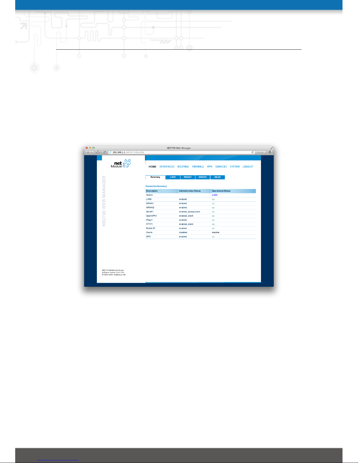
This page provides a status overview of established connections and enabled features.
It offers a summary about the administrative and operational status of the router’s
interfaces. Further details about any enabled Wide Area Network (WAN) links (such as
the IP addresses, network information, signal strength, etc.) will be shown on additional
tabs. The information about the amount of downloaded/uploaded data is stored in nonvolatile memory, thus survive a reboot of the system.
The counters can be reset by pressing the Reset button.
Figure 5.1.: Home
25
Page 26

NB2700 User Manual
5.3. INTERFACES
5.3.1. WAN
Link Management
Depending on your hardware model, WAN links can be made up of either Wireless
Wide Area Network (WWAN), Wireless LAN (WLAN), Ethernet or PPP over Ethernet
(PPPoE) connections. Please note that each WAN link has to be configured and enabled
in order to appear on this page.
Generally, a link will be only dialed or declared as up if the following prerequisites are
met:
Condition WWAN WLAN ETH PPPoE
Modem is registered X
Registered with valid service type X
Valid SIM state X
Sufficient signal strength X X
Client is associated X
Client is authenticated X
Valid DHCP address retrieved X X X X
Link is up and holds address X X X X
Ping check succeeded X X X X
Table 5.1.: WAN Link Prerequisites
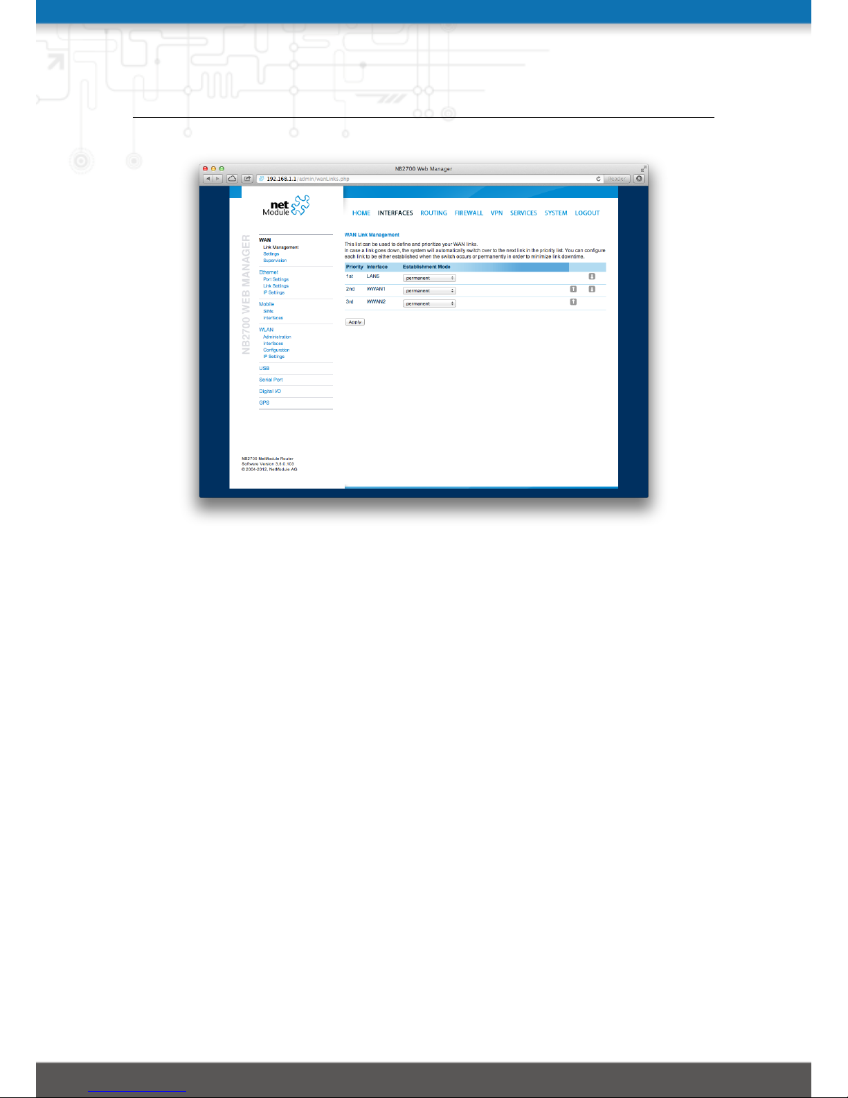
The menu can be used further to prioritize your WAN links. The highest priority link
which has been established successfully will become the so-called hotlink which holds
the default route for outgoing packets.
In case a link goes down, the system will automatically switch over to the next link in
the priority list. You can configure each link to be either established when the switch
occurs or permanently in order to minimize link downtime.
1st priority: The primary link which will be used whenever possible.
2nd priority: The first fallback link, it can be enabled permanently or being dialed as
soon as Link 1 goes down.
3rd priority: The second fallback link, it can be enabled permanently or being dialed as
soon as Link 2 goes down.
4th priority: The third fallback link, it can be enabled permanently or being dialed as
26
Page 27
NB2700 User Manual
Figure 5.2.: WAN Links
soon as Link 3 goes down.
Links are being triggered periodically and put to sleep in case it was not possible to
establish them within a certain amount of time. Hence it might happen that permanent
links will be dialed in background and, as soon as they got established, replace lowpriority links again.
We recommend to use the permanent option for WAN links in general. However, in case
of time-limited mobile tariffs for instance, the switchover option might be applicable.
Settings
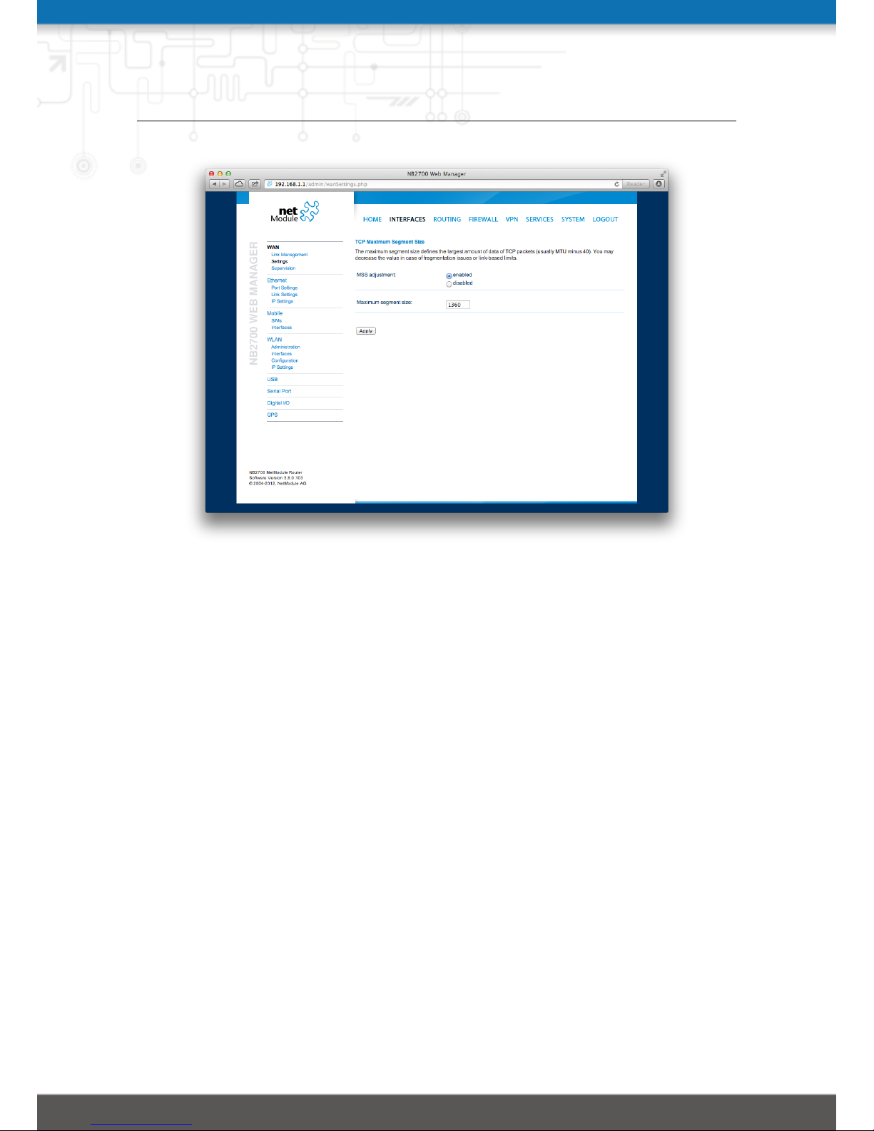
This page can be used to configure WAN specific settings like the Maximum Segment Size
(MSS). The MSS corresponds to the largest amount of data (in bytes) that the router
can handle in a single, unfragmented TCP segment. In order to avoid any negative side
effects the number of bytes in the data segment and the headers must not add up to
more than the number of bytes in the Maximum Transmission Unit (MTU). The MTU
can be configured per each interface and corresponds to the largest packet size that can
be transmitted.
MSS adjustment: Enable or disable MSS adjustment on WAN interfaces.
Maximum segment size: Maximum number of bytes in a TCP data segment.
27
Page 28
NB2700 User Manual
Figure 5.3.: WAN Settings
Supervision
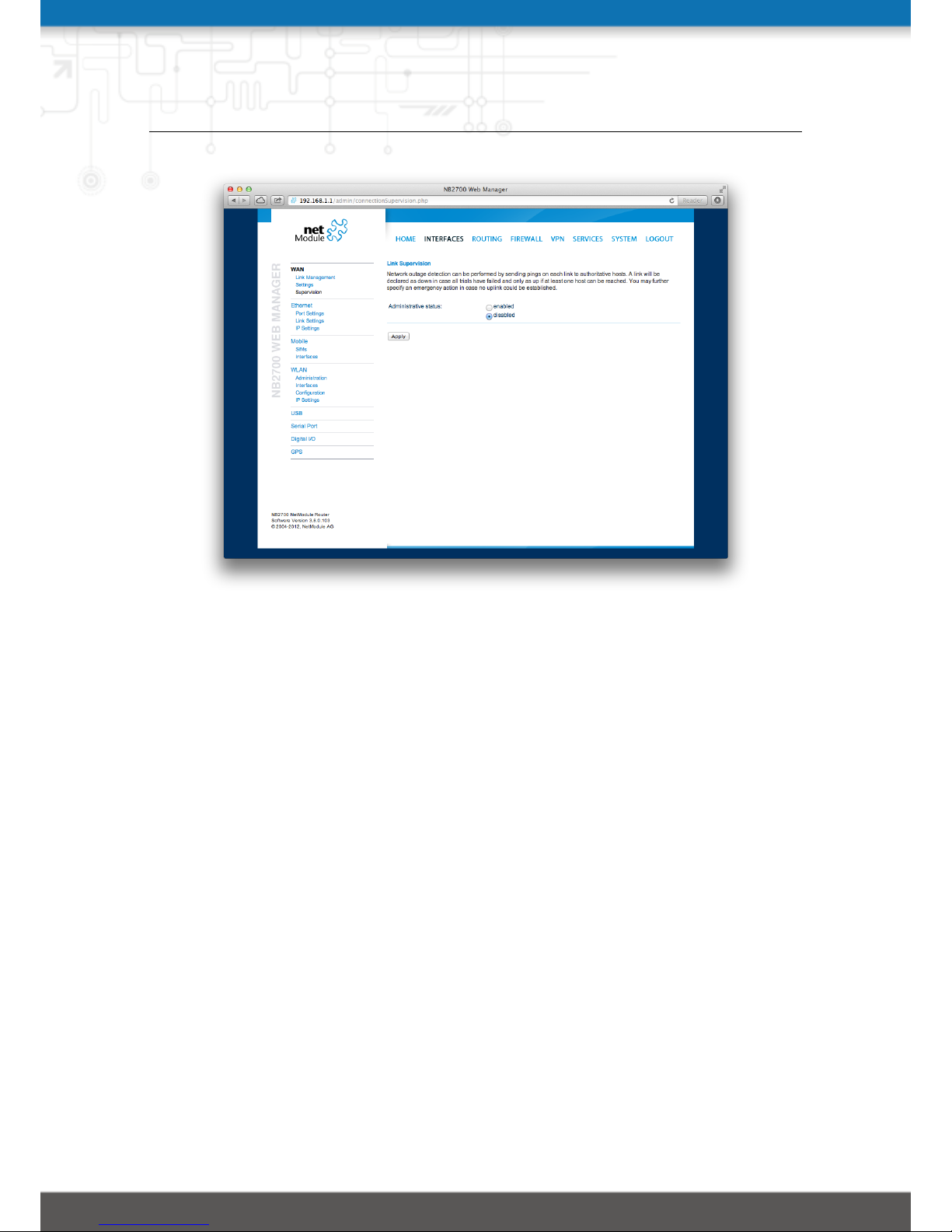
Network outage detection can be performed by sending pings on each link to some
authoritative hosts. A link will be declared as down in case all trials have failed and
only as up if at least one host can be reached.
Administrative status: Enable or disable link supervision
Primary host: The primary host which will be monitored
Secondary host: The secondary host which will be monitored (optional)
Ping timeout: The amount of time in milliseconds a response for a single ping can
take. Consider to increase this value in case of slow and tardy links (such as 2G
connections)
Ping interval: The interval in seconds at which pings are transmitted on each interface
Max. number of failed trials: The maximum number of failed ping trials until the ping
check will be declared as failed
You may further specify an emergency action in case no uplink can be established at
all. You can choose between rebooting the system or restarting all involved link services
after a specific maximum downtime is reached.
Emergency action: The emergency action which should be taken after max. downtime
reached. Using reboot would perform a reboot of the system, restart services
28
Page 29
NB2700 User Manual
Figure 5.4.: Link Supervision
will restart all link-related applications including a reset of the modems.
Maximum downtime: The maximum amount of downtime in minutes for which no
WAN link could be established
29
Page 30
NB2700 User Manual
5.3.2. Ethernet
Port Settings
Figure 5.5.: LAN Ports
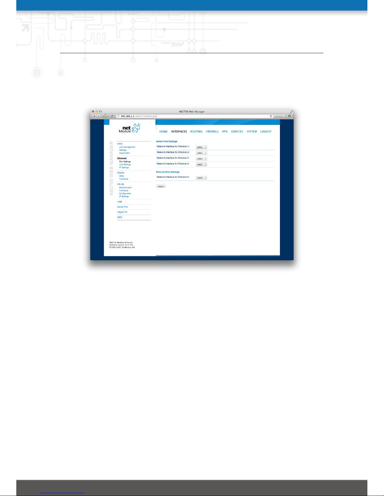
This menu can be used to individually assign each Ethernet port to a LAN interface, just
in case you want to have different subnets per port or use one port as WAN interface. You
may assign multiple ports to the same interface. Please note that on systems without
an Ethernet switch, the ports will be bridged by software then and operated by running
the Spanning Tree Protocol (STP).
Link Settings
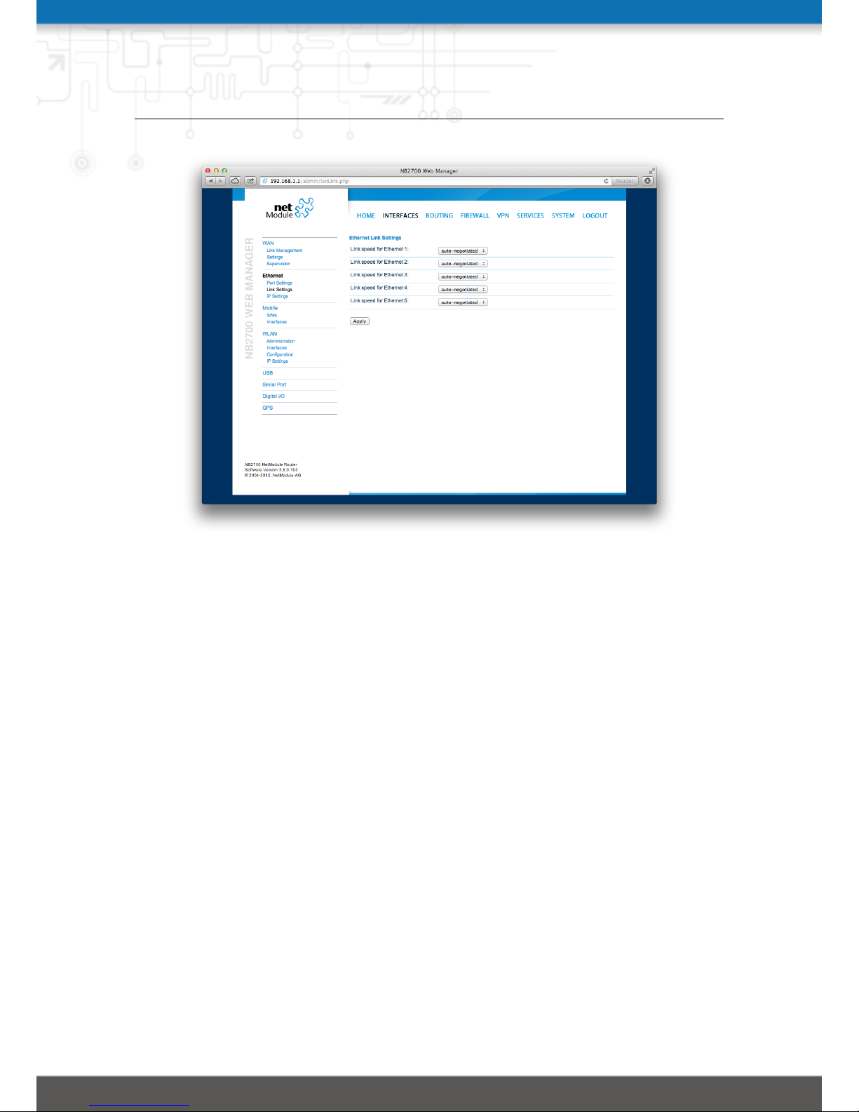
Link negotiation can be set for each Ethernet port individually. Most devices support
auto-negotiation which will configure the link speed automatically to comply with other
devices in the network. In case of negotiation problems, you may assign the modes
manually but it has to be ensured that all devices in the network utilize the same
settings then.
IP Settings
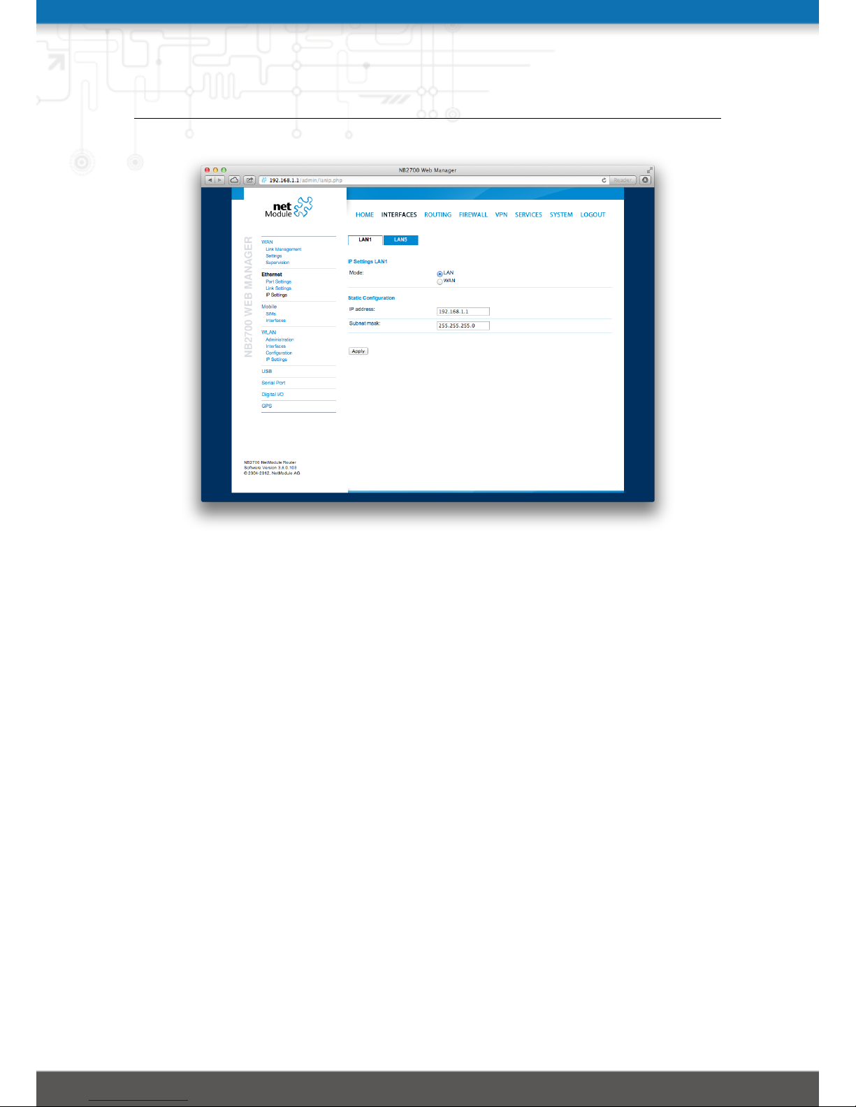
This page can be used to configure IP addressing for your LAN/WAN Ethernet interfaces.
30
Page 31
NB2700 User Manual
Figure 5.6.: LAN Link Settings
Please keep in mind that the DNS servers can be set globally in the DNS server configuration menu. But as soon as a link comes up it will use the interface-specific nameservers (e.g. the ones being retrieved over DHCP) and update the resolver configuration
accordingly.
Mode: Defines whether this interface is being used as LAN or WAN interface
When running in LAN mode the interface accepts the following static settings:
IP address: The IP interface address
Subnet mask: The subnet mask for this interface
When running in WAN mode the interface may be configured with the following settings:
WAN mode: The WAN operation mode, defines whether the interface should run as
DHCP client, statically configured or over PPPoE
MTU: The maximum transfer unit for the interface, if provided it will specify the largest
size of a packet
When running as DHCP client, no further configuration is required because all IP-related
settings (address, subnet, gateway, DNS server) will be retrieved from a DHCP server
31
Page 32
NB2700 User Manual
Figure 5.7.: LAN IP Configuration
in the network. You may also define static values but caution has to be taken to assign
an unique IP address as it would otherwise raise IP conflicts in the network.
PPPoE is commonly used when communicating with another WAN access device (like
a DSL modem). The following settings can be applied:
User name: PPPoE user name for authenticating at the access device
Password: PPPoE password for authenticating at the access device
Service name: Specifies the service name set of the access concentrator and can be left
blank unless you have multiple services on the same physical network and need to
specify the one you want to connect to
Access concentrator name: The name of the concentrator (the PPPoE client will con-
nect to any access concentrator if left blank)
32
Page 33
NB2700 User Manual
5.3.3. Mobile
SIMs
Figure 5.8.: SIMs
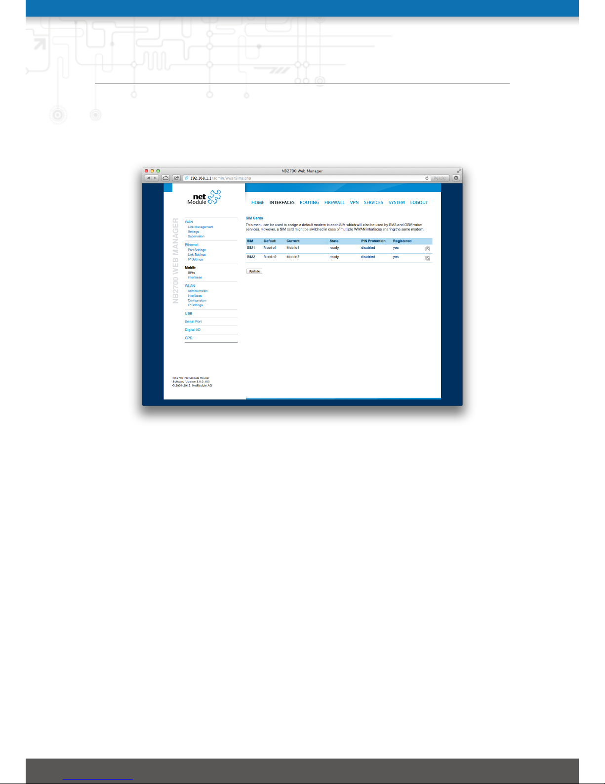
The SIM page gives an overview about the available SIM cards, their assigned modems
and the current state. Once a SIM card has been inserted, assigned to a modem and
successfully unlocked, the card should remain in state ready and the network registration
status should have turned to registered. If not, please double-check your PIN.
Please keep in mind that registering to a network usually takes some time and depends
on signal strength and possible radio interferences. You may hit the Update button
at any time in order to restart PIN unlocking and trigger another network registration
attempt.
Under some circumstances (e.g. in case the modem flaps between base stations) it
might be necessary to set a specific service type or assign a fixed operator. The list
of operators around can be obtained by initiating a network scan (may take up to 60
seconds). Further details can be retrieved by querying the modem directly, a set of
suitable commands can be provided on request.
Configuration
33
Page 34

NB2700 User Manual
A SIM card is generally assigned to a default modem but might be switched, for instance
if you set up two WWAN interfaces with one modem but different SIM cards.
Close attention has to be paid when other services (such as SMS or Voice) are operating
on that modem, as a SIM switch will naturally affect their operation.
The following settings can be applied:
Default modem: The default modem assigned to this SIM card
Service type: The service type to be used by default with this SIM card. Remember
that the link manager might change this in case of different settings. The default
is to use automatic, in areas with interfering base stations you can force a specific
type (e.g. 3G-only) in order to prevent any flapping between the stations around.
PIN protection: Depending on the used card, it can be necessary to unlock the SIM
with a PIN code. Please check the account details associated with your purchased
SIM and figure out whether it is protected with a PIN.
PIN code: The PIN code for unlocking the SIM card
SMS gateway: The service center number for sending short messages. It is generally
retrieved automatically from your SIM card but you may define a fix number here.
Network
This page provides information about the current network status, signal strength and
the Local Area Identifier (LAI) to which the modem has been registered. An LAI is
a globally unique number that identifies the country, network provider and Local Area
Code (LAC, group of base stations) of any given location area. It can be used to force
the modem to register to a particular mobile cell in case of competing stations.
You may further initiate a mobile network scan for getting networks in range and assign
an LAI manually.
Query
This page allows you to send Hayes AT commands to the modem. Besides the 3GPPconforming AT command-set further modem-specific commands can be applicable which
we can provide on demand. Some modems also support running Unstructured Supplementary Service Data (USSD) requests, e.g. for querying the available balance of a
prepaid account.
34
Page 35
NB2700 User Manual
WWAN Interfaces
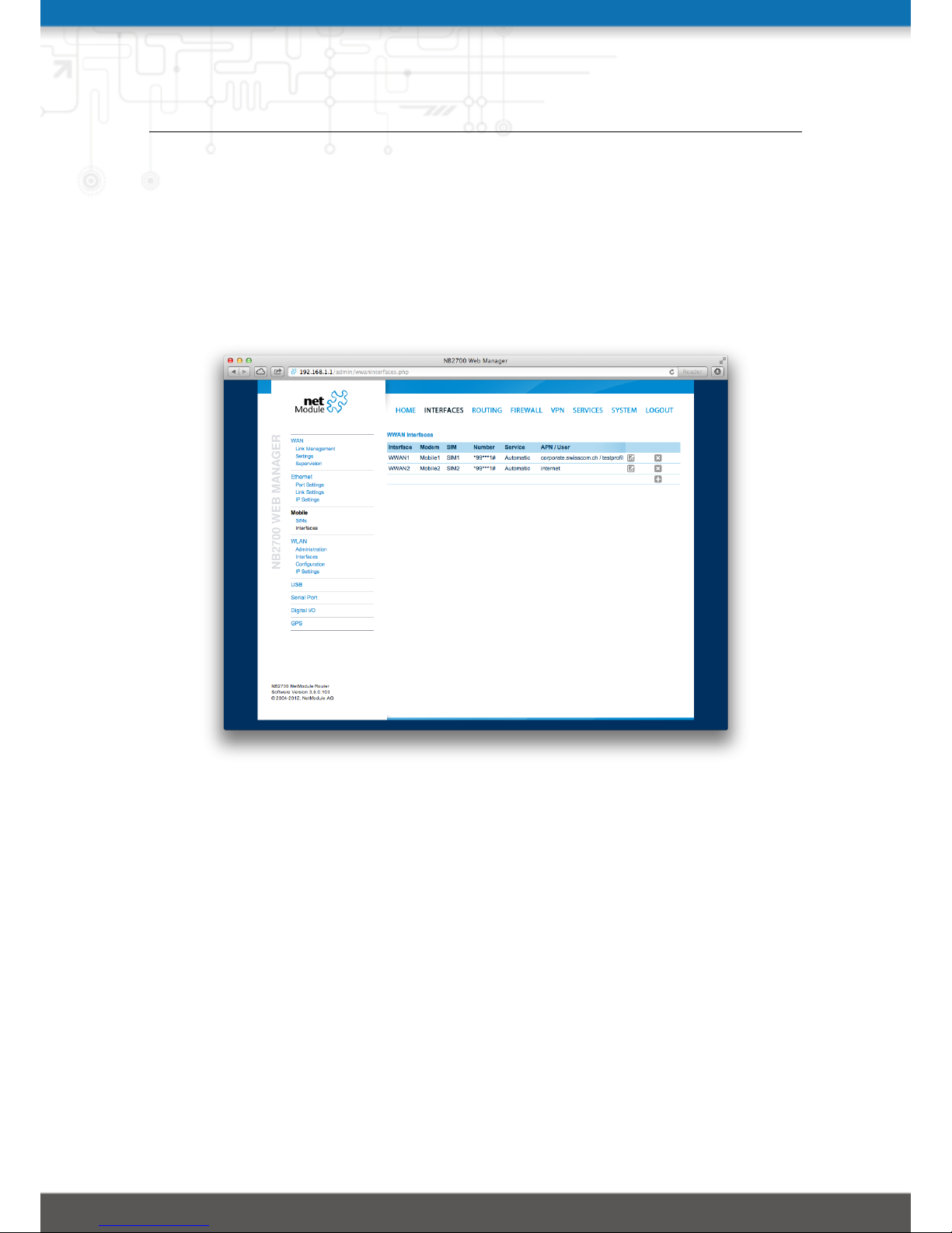
This page can be used to manage your WWAN interfaces. The resulting link will pop
up automatically as WAN link once an interface has been added. Please refer to chapter 5.3.1 for how to manage them.
The Mobile LED will be blinking during the connection establishment process and goes
on as soon as the connection is up. Refer to section 5.8.5 or consult the system log files
for troubleshooting the problem in case the connection did not come up.
Figure 5.9.: WWAN Interfaces
The following mobile settings are required:
Modem: The modem to be used for this WWAN interface
SIM: The SIM card to be used for this WWAN interface
Service type: The required service type
Please note that these settings supersede the general SIM based settings as soon as the
link is being dialed.
Generally, the connection settings are derived automatically as soon as the modem has
registered and the network provider has been found in our database. Otherwise, it will
be required to configure the following settings manually:
Phone number: The phone number to be dialed, for 3G+ connections this commonly
refers to be *99***1#. For circuit-switched 2G connections you can enter the fixed
35
Page 36

NB2700 User Manual
phone number to be dialed in international format (e.g. +41xx).
Access point name: The access point name (APN) being used
Authentication: The authentication scheme being used, if required this can be PAP
or/and CHAP
Username: The user-name used for authentication
Password: The password used for authentication
Furtheron, you may configure the following advanced settings:
Required signal strength: Sets a minimum required signal strength before the connec-
tion is dialed
Home network only: Determines whether the connection should only be dialed when
registered to a home network
Negotiate DNS: Specifies whether the DNS negotiation should be performed and the
retrieved name-servers should be applied to the system
Call to ISDN: Has to be enabled in case of 2G connections talking to an ISDN modem
IP header compression: Enables or disables Van Jacobson TCP/IP Header Compres-
sion for PPP-based connections. This feature will improve TCP/IP performance
over slow serial links. Has to be supported by your provider.
Software compression: Enables or disables data compression for PPP-based connec-
tions. Software compression reduces the size of packets to improve throughput.
Has to be supported by your provider.
Client address: Specifies a fixed client IP address on the mobile interface
MTU: The Maximum Transmission Unit represents the largest amount of data that can
be transmitted within one IP packet and can be defined for any WAN interface.
36
Page 37
NB2700 User Manual
5.3.4. WLAN
WLAN Management
In case your router is shipping with a WLAN (or Wi-Fi) module you can operate it
either as client or access point. As a client it can create an additional WAN link
which for instance can be used as backup link. As access point, it can form another LAN
interface which can be either bridged to an Ethernet-based LAN interface or create a
self-contained IP interface which can be used for routing and to provide services (such
as DHCP/DNS/NTP) in the same way like an Ethernet LAN interface does.
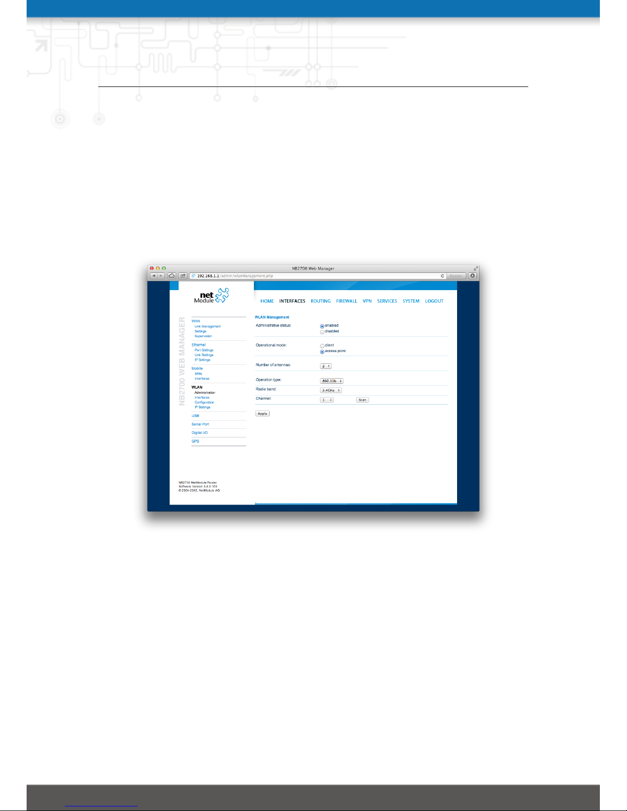
Figure 5.10.: WLAN Management
If the administrative status is set to disabled, the module will be powered off in order
to reduce the overall power consumption. Regarding antennas, we generally recommend
using two antennas for better coverage and throughput. A second antenna is definitely
mandatory if you want to achieve higher throughput rates in 802.11n.
A WLAN client will automatically became a WAN link and can be managed as described in chapter 5.3.1.
Running as access point, you can further configure the following settings:
Operation type: Specifies the desired IEE 802.11 operation mode, 802.11a can be used
in the 5 GHz band, higher throughput in 20/40 MHz mode can be achieved with
37
Page 38
NB2700 User Manual
802.11n
Radio band: Selects the radio band to be used for connections, depending on your
module it could be 2.4 or 5 GHz
Channel: Specifies the channel to be used
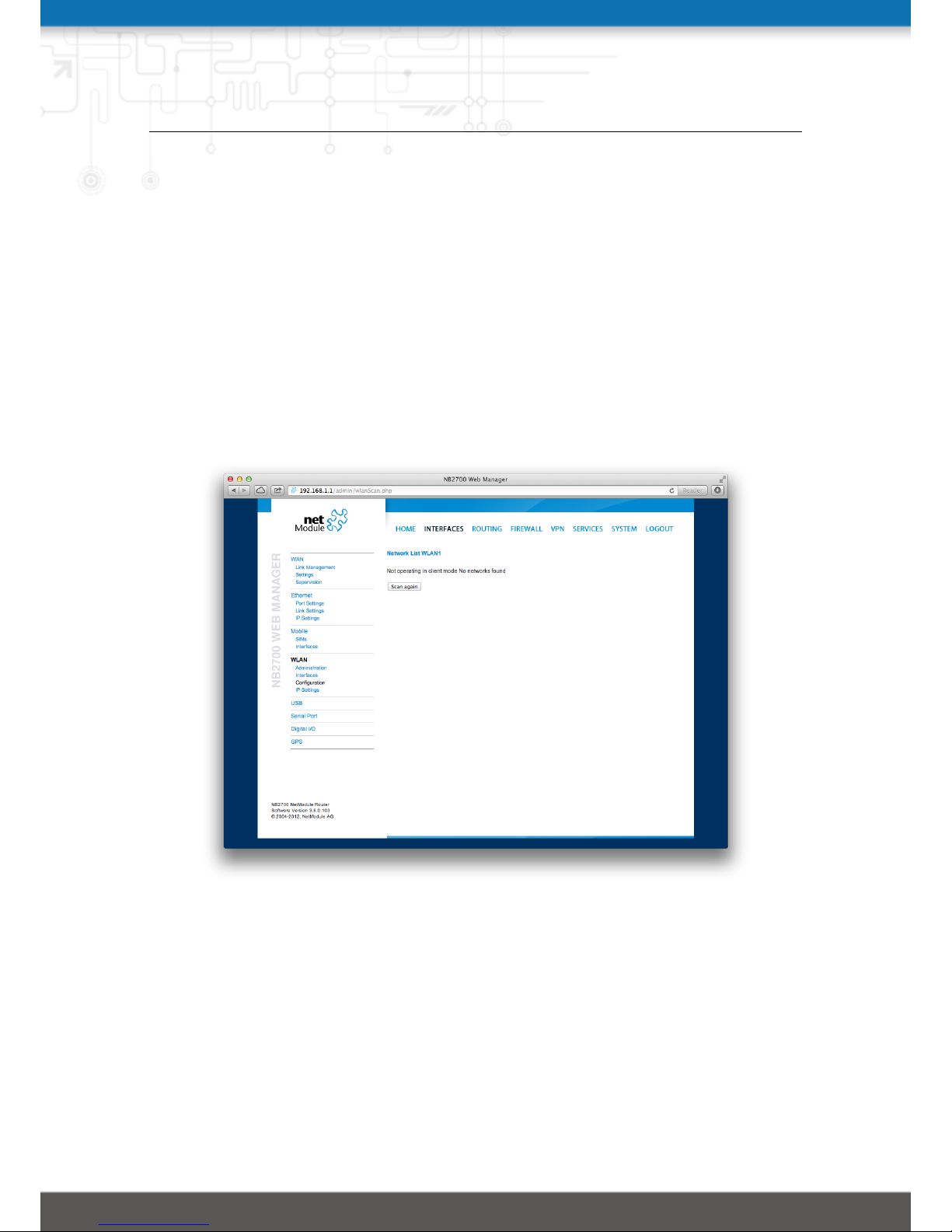
Prior to setting up an access point, it is always a good idea to run a network scan
for getting a list of neighboring WLAN networks and then choose the less interfering
channel. Please keep in mind that two adequate channels are required for getting good
throughputs with 802.11n in the 40 MHz radio band.
Running in client mode, you can select the network to which you want to connect to
and enter the required authentication settings. You may also perform a WLAN network
scan and pick the settings from the discovered information directly. The credentials can
be obtained by the operator of your WLAN access point.
Figure 5.11.: WLAN Scan
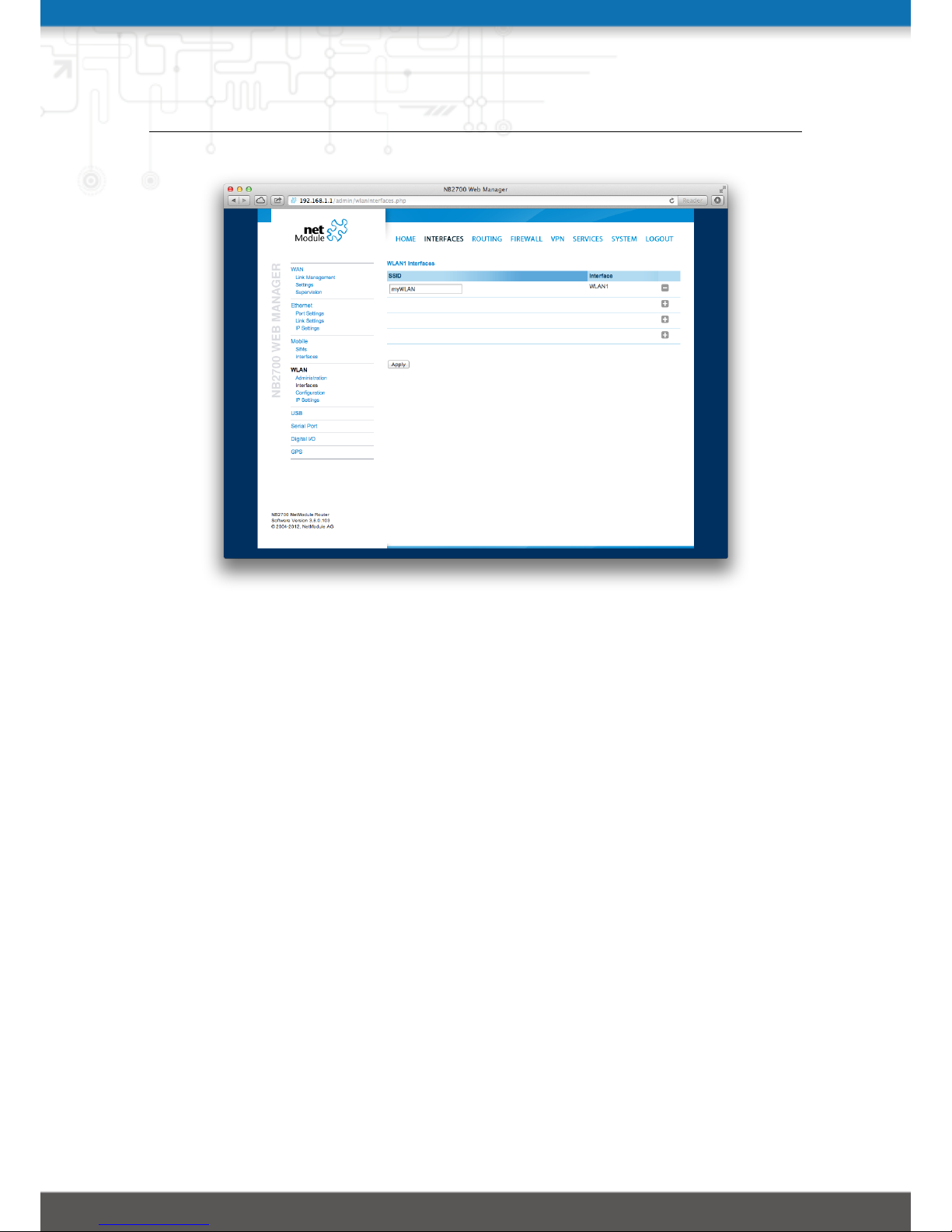
WLAN Interfaces
An access point can define up to 4 networks being broadcasted. The networks can
be individually bridged to a LAN interface or operate as dedicated interface in routingmode.
38
Page 39
NB2700 User Manual
Figure 5.12.: WLAN Interfaces
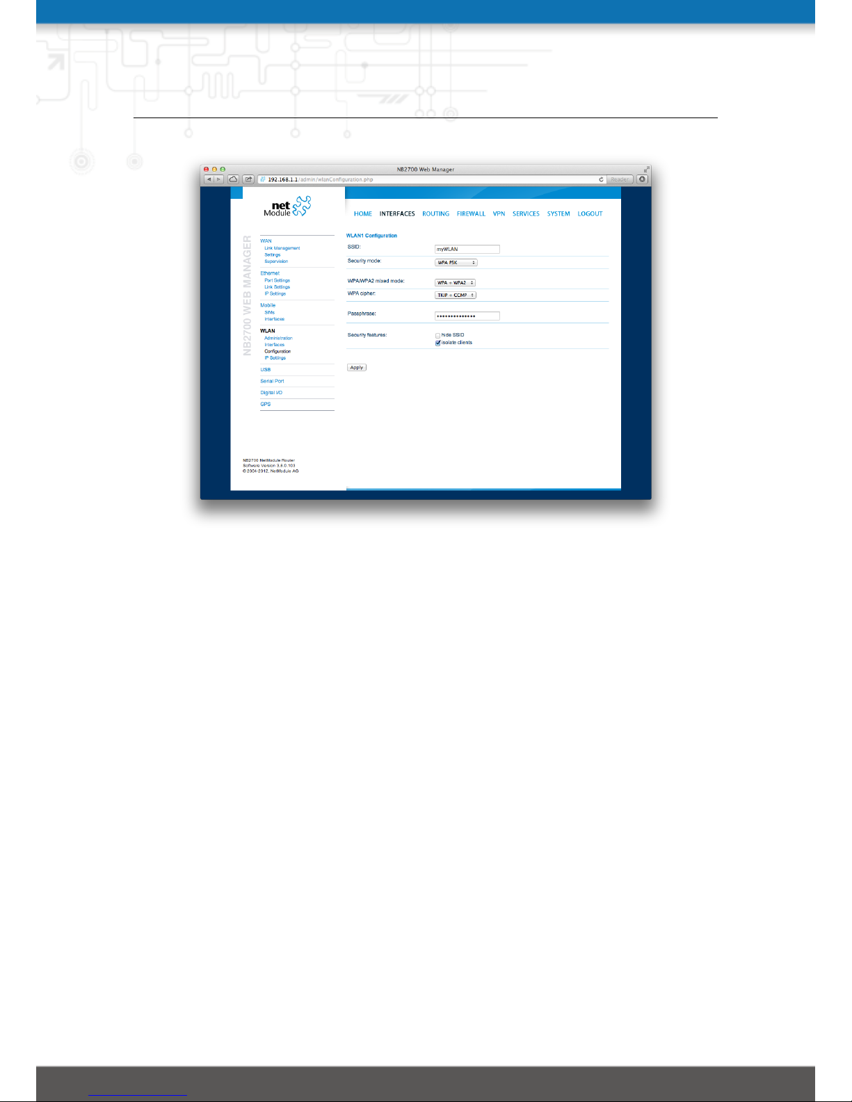
WLAN Configuration
Running in access point mode you can define up to 4 SSIDs with each running their
own network configuration. This section can be used to configure security-related settings.
SSID: The network name (called SSID)
Security mode: The desired security mode (such as WPA PSK), WPA (802.1x) can be
used to authenticate against a remote RADIUS server which can be configured in
chapter 5.8.2
WPA/WPA2 mixed mode: WPA2 should be preferred over WPA1, running WPA/WPA2
mixed-mode offers both
WPA cipher: The WPA cipher to be used, the default is to run both (TKIP and CCMP)
Passphrase: The passphrase used for authentication
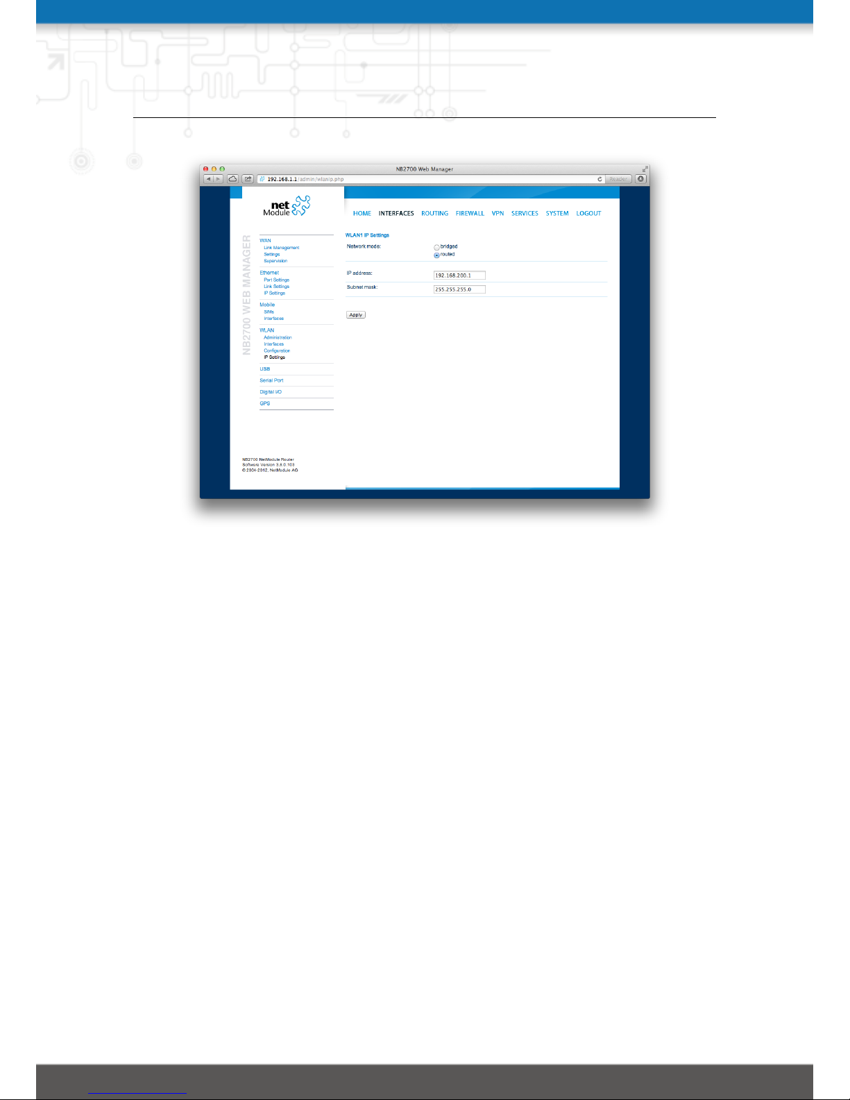
WLAN IP Settings
This section lets you configure the TCP/IP settings of your WLAN network.
A client interface can be run over DHCP or with a statically configured address and
default gateway.
The access point networks can be bridged to any LAN interface for letting WLAN
39
Page 40
NB2700 User Manual
Figure 5.13.: WLAN Configuration
clients and Ethernet hosts operate in the same subnet. However, for multiple SSIDs we
strongly recommend to set up separated interfaces in routing-mode in order to avoid
unwanted access and traffic between the interfaces. The corresponding DHCP server for
each network can be configured in afterwards as described in chapter 5.7.2.
Network mode: Choose whether the interface shall be operated bridged or in routing-
mode
Bridge interface: If bridged, the LAN interface to which the WLAN network should be
bridged
IP address / netmask: In routing-mode, the IP address and netmask for this WLAN
network
40
Page 41
NB2700 User Manual
Figure 5.14.: WLAN IP Configuration
5.3.5. USB
NetModule routers ship with a standard USB 2.0 host port which can be used to connect
any arbitrary USB device.
USB Autorun
This feature can be used to automatically launch a shell script or perform a software/config update as soon as an USB storage stick has been plugged in. For authentication, a
file called autorun.key must exist in the root directory of a FAT16/32 formatted stick.
It can be downloaded from that page and corresponds to the SHA256 Hash of the admin
password. The file can hold multiple hashes which will be processed line-by-line during authentication which can be used for setting up more systems with different admin
passwords.
Once authentication has succeeded, the system scans for other files in the root directory
which can perform the following actions:
1. For running a script: autorun.sh
2. For a configuration update: cfg-<SERIALNO>.zip (e.g. cfg-00112B000815.zip)
3. For a software update: sw-update.img
41
Page 42
NB2700 User Manual
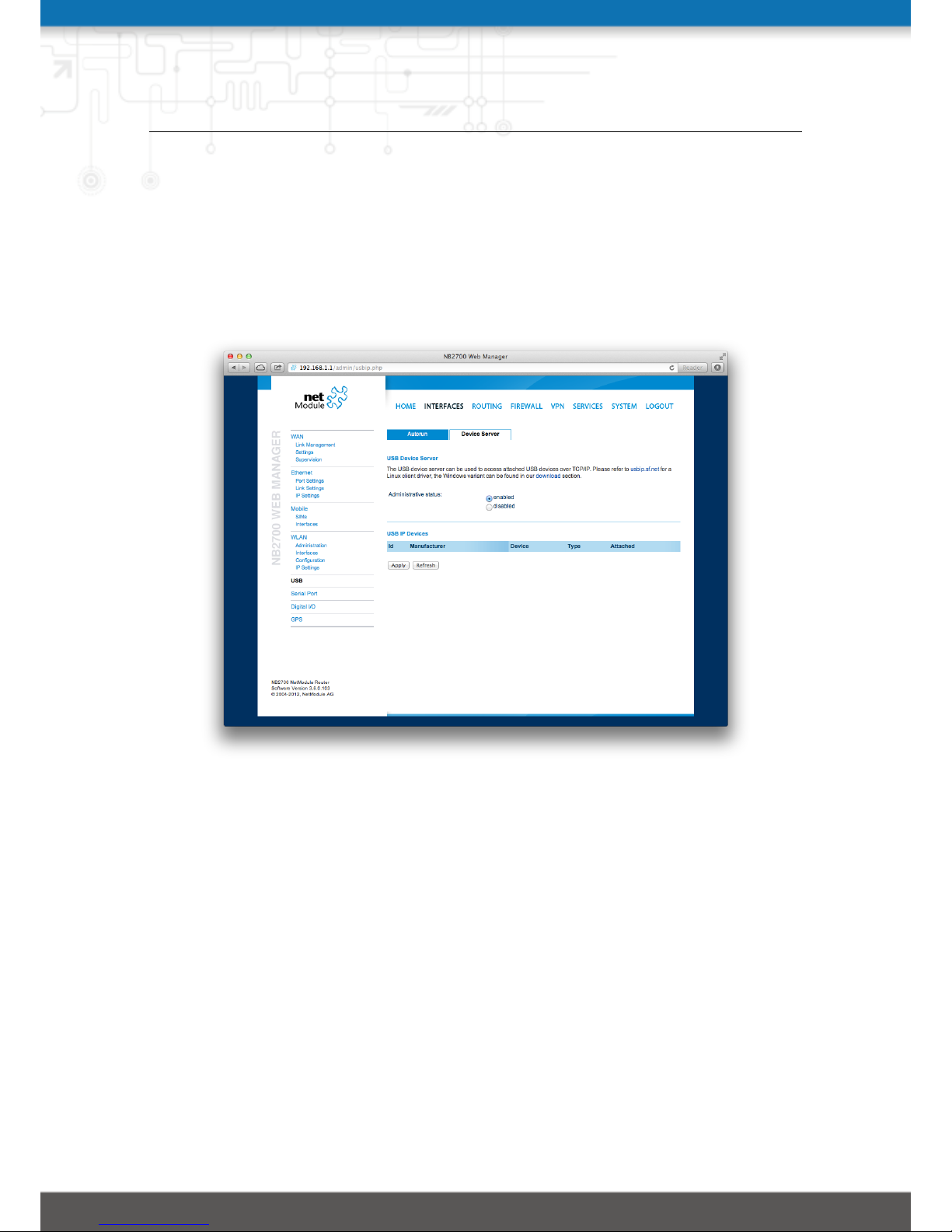
USB Device Server
As soon as the USB device server has been enabled you can refresh the discovered USB
devices plugged in and attach them to the USB/IP server. Enabled devices can now
be exported to a remote host. You will need an additional driver on the remote site
(a pre-packed Windows driver package can be obtained from http://www.netmodule.
com/products) and further installation instructions which we will happily provide on
demand.
Figure 5.15.: USB Device Server
Please note, that some USB devices behave latency-sensitive which may raise problems
when run over a slow IP connection. In addition, it may also happen that the device
driver is not able to work with the USB/IP driver. Please contact our support in case
of compatibility issues.
42
Page 43
NB2700 User Manual
5.3.6. Serial Port
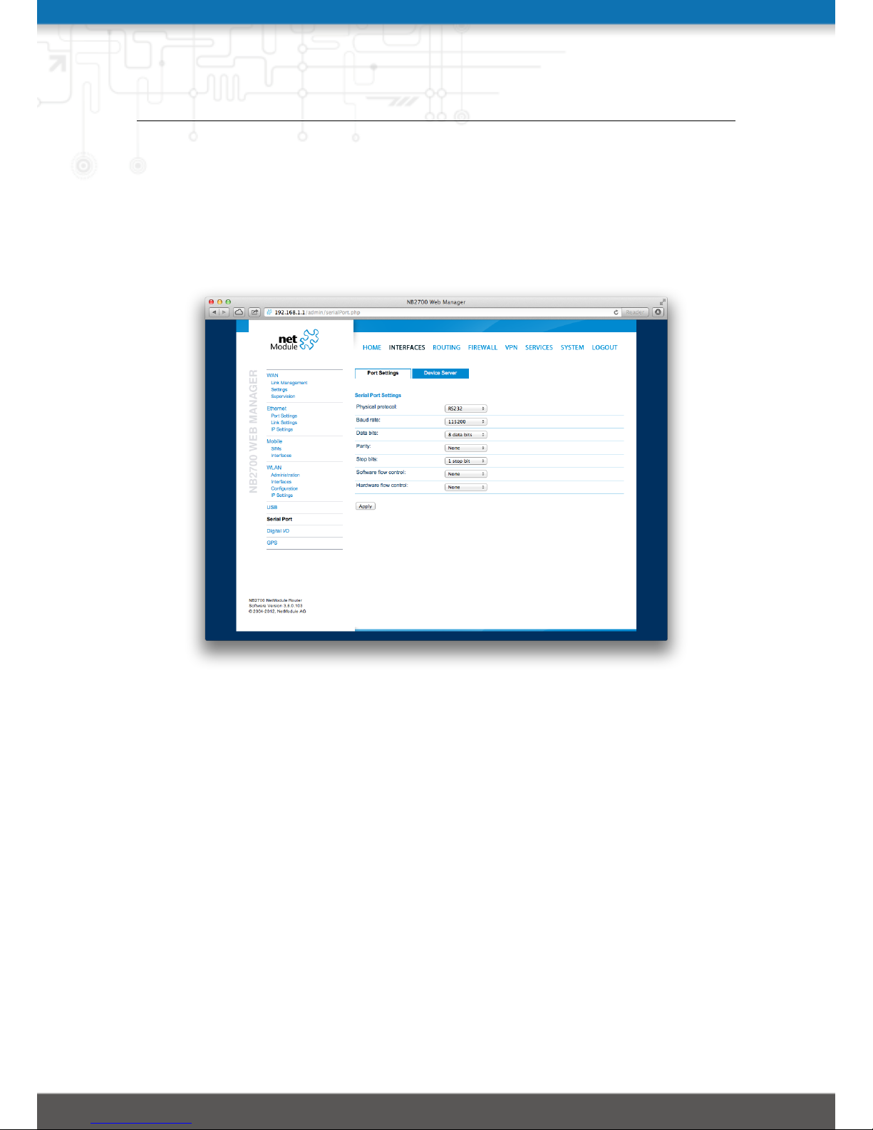
This page can be used to manage your serial ports. They can be used for various purposes
on the system. When set to none it will be disabled, when set to login console you
would be able to get a login shell when connecting to the serial port (115200 8N1). You
may also mark them as reserved for SDK scripts.
Figure 5.16.: Serial Port
Furtheron, a device server can be run for each port which can be used to control the
serial device via IP.
It can be configured as follows:
Physical protocol: Selects the desired physical protocol on the serial port
Baud rate: Specifies the baud rate run on the serial port
Data bits: Specifies the number of data bits contained in each frame
Parity: Specifies the parity used for every frame that is transmitted or received
Stop bits: Specifies the number of stop bits used to indicate the end of a frame
Software flow control: Defines the software flow control for the serial port, XOFF will
send a stop, XON a start character to the other end to control the rate of any
incoming data
Hardware flow control: You may enable RTS/CTS hardware flow control, so that the
43
Page 44

NB2700 User Manual
RTS and CTS lines are used to control the flow of data
Protocol on TCP/IP: You may choose the IP protocols Telnet or TCP raw for the
device server
Port: The TCP port for the device server
Timeout: The timeout until a client is declared as disconnected
44
Page 45

NB2700 User Manual
5.3.7. Digital I/O
The Digital I/O page displays the current status of the I/O ports and can be used to
turn output ports on or off.
You can apply the following settings:
DO1 after reboot: Initial status of DO1 after system has booted
DO2 after reboot: Initial status of DO2 after system has booted
Besides on and off you may keep the default status as the hardware has initialized it
after power-up.
The digital inputs and outputs can also be monitored and controlled by SDK scripts.
45
Page 46

NB2700 User Manual
5.3.8. GPS
Administration
The GPS page lets you enable or disable the GPS modules present in the system and can
be used to configure the daemon that can be used to share access to receivers without
contention or loss of data and to respond to queries with a format that is substantially
easier to parse than the NMEA 0183 emitted directly by the GPS device.
We are currently running the Berlios GPS daemon (version 2.37), please navigate to
http://gpsd.berlios.de for getting more information about how to incorporate it.
The GPS values can also be queried by the CLI and used in SDK scripts.
Administrative status: Enable or disable GPS reception
Antenna type: The type of the connected GPS antenna, either active or passive
Server port: The TCP port on which the daemon is listening for incoming connections
Allow clients from: Specifies where clients can connect from, can be either everywhere
or from a specific network
Clients start mode: Specifies how client reception is started upon connect. You can
specify on request, which typically requires an R to be sent, or raw/super-raw
mode which will transmit NMEA frames to the client instantly
Position
This page shows the current position of the box together with a location map.
Information
This pages provides further information about the satellites in view and values derived
from them:
Latitude: The geographic coordinate specifying the north-south position
Longitude: The geographic coordinate specifying the east-west position
Altitude: The height above sea level of the current location
Satellites in view: The number of satellites in view as stated in GPGSV frames
Speed: The horizontal and vertical speed in meter per second as stated in GPRMC
frames
Satellites used: The number of satellites used for calculating the position as stated in
GPGGA frames
Dilution of precision: The dilution of precision as stated in GPGSA frames
Furtheron, each satellite also comes with the following details:
PRN: The PRN code of the satelitte (also referred as satellite ID) as stated in GPGSA
frames
Elevation: The elevation (up-down angle between the dish pointing direction) in degrees
as stated in GPGSV frames
46
Page 47

NB2700 User Manual
Azimuth: The azimuth (rotation around the vertical axis) in degrees as stated in GPGSV
frames
SNR: The SNR (Signal to Noise Ratio), often referred as signal strength
Please note that the values are shown as calculated by the daemon, their accuracy might
be suggestive.
47
Page 48
NB2700 User Manual
5.4. ROUTING
5.4.1. Static Routes
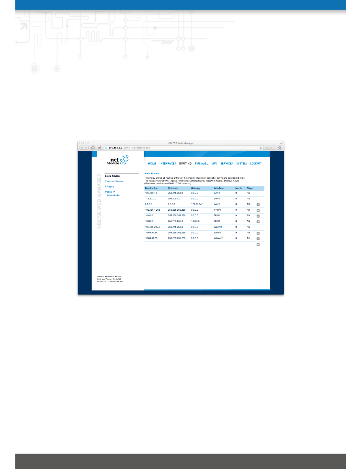
This menu shows all routing entries of the system. They are typically formed by an
address/netmask couple (represented in IPv4 dotted decimal notation) which specify
the destination of a packet. The packets can be directed to either a gateway or an
interface or both. If interface is set to ANY, the system will choose the route interface
automatically, depending on the best matching network configured for an interface.
Figure 5.17.: Static Routing
In general, host routes precede network routes and network routes precede default routes.
Additionally, a metric can be used to determine the priority of a route, a packet will go
in the direction with the lowest metric in case a destination matches multiple routes.
Netmasks can be specified in CIDR notation (i.e. /24 expands to 255.255.255.0).
Destination: The destination address of a packet
Netmask: The subnet mask which forms, in combination with the destination, the net-
work to be addressed. A single host can be specified by a netmask of 255.255.255.255,
a default route corresponds to 0.0.0.0.
Gateway: The next hop which operates as gateway for this network (can be omitted on
peer-to-peer links)
48
Page 49

NB2700 User Manual
Interface: The network interface on which a packet will be transmitted in order to reach
the gateway or network behind it
Metric: The routing metric of the interface (default 0), higher metrics have the effect
of making a route less favorable
Flags: (A)ctive, (P)ersistent, (H)ost Route, (N)etwork Route, (D)efault Route
The flags obtain the following meanings:
Flag Description
A The route is considered active, it might be inactive if the
interface for this route is not yet up.
P The route is persistent, which means it is a configured route,
otherwise it corresponds to an interface route.
H The route is a host route, typically the netmask is set to
255.255.255.255.
N The route is a network route, consisting of an address and
netmask which forms the subnet to be addressed.
D The route is a default route, address and netmask are set
to 0.0.0.0, thus matching any packet.
Table 5.2.: Static Route Flags
49
Page 50
NB2700 User Manual
5.4.2. Extended Routing
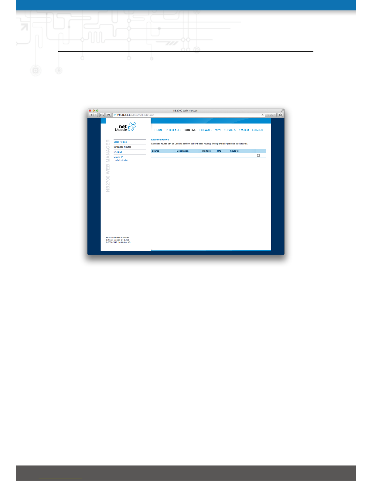
Extended routes can be used to perform policy-based routing, they generally precede
static routes.
Figure 5.18.: Extended Routing
In contrast to statis routes, extended routes can be made up, not only of a destination
address/netmask, but also a source address/netmask, incoming interface and the type
of service (TOS) of packets.
Source address: The source address of a packet
Source netmask: The source address of a packet
Destination address: The destination address of a packet
Destination netmask: The destination address of a packet
Incoming interface: The interface on which the packet enters the system
Type of service: The TOS value within the header of the packet
Route to: Specifies the target interface or gateway to where the packet should get routed
to
50
Page 51
NB2700 User Manual
5.4.3. Bridging
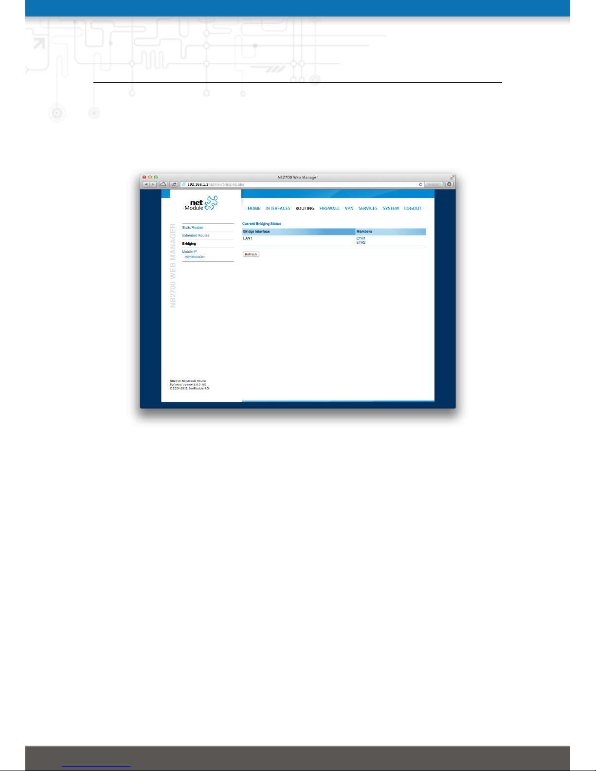
This menu shows the currently configured bridge groups and their interface members.
Please refer to section A.1 for a list of interface abbrevations.
Figure 5.19.: Bridging
51
Page 52

NB2700 User Manual
5.4.4. Mobile IP
Mobile IP (MIP) can be used to enable seamless switching between different kinds of
WAN links (e.g. WWAN/WLAN). The mobile node hereby remains reachable via the
same IP address (home address) at any time, independently of the WAN link being
used. Effectively, any WAN link switch causes very small outages during switchover
while keeping all IP connections alive.
Moreover, NetModule routers also support NAT-Traversal for mobile nodes running
behind a firewall (performing NAT), which makes mobile nodes even there accessible
from a central office via their home address, and thus, bypassing any complicated VPN
setups.
The home agent accomplishes this by establishing a tunnel (similar to a VPN tunnel)
between itself and the mobile node. WAN link switching works by telling the home
agent that the WAN IP address (called the care-of address in MIP terms) of the
mobile node has changed. The home agent will then encapsulate packets destined to
a mobile node’s home address into a tunnel packet containing the current care-of
address of the mobile node as its destination address.
To prevent problems with firewalls and private IP addressing, the MIP implementation
always employs reverse tunneling, which means that all traffic sent by a mobile node is
relayed via the tunnel to the home agent instead of directly being conveyed to the final
destination. This fact also empowers MIP to be used as a lightweight VPN replacement
(without payload secrecy).
The MIP implementation supports RFCs 3344, 5177, 3024 and 3519. For applications
requiring vast numbers of mobile nodes, interoperability with the Cisco 2900 Series home
agent implementation has been verified. However, since NetModule routers implement
a mobile node as well as a home agent, a MIP network with up to 10 mobile nodes
can be implemented without requiring expensive third party routers.
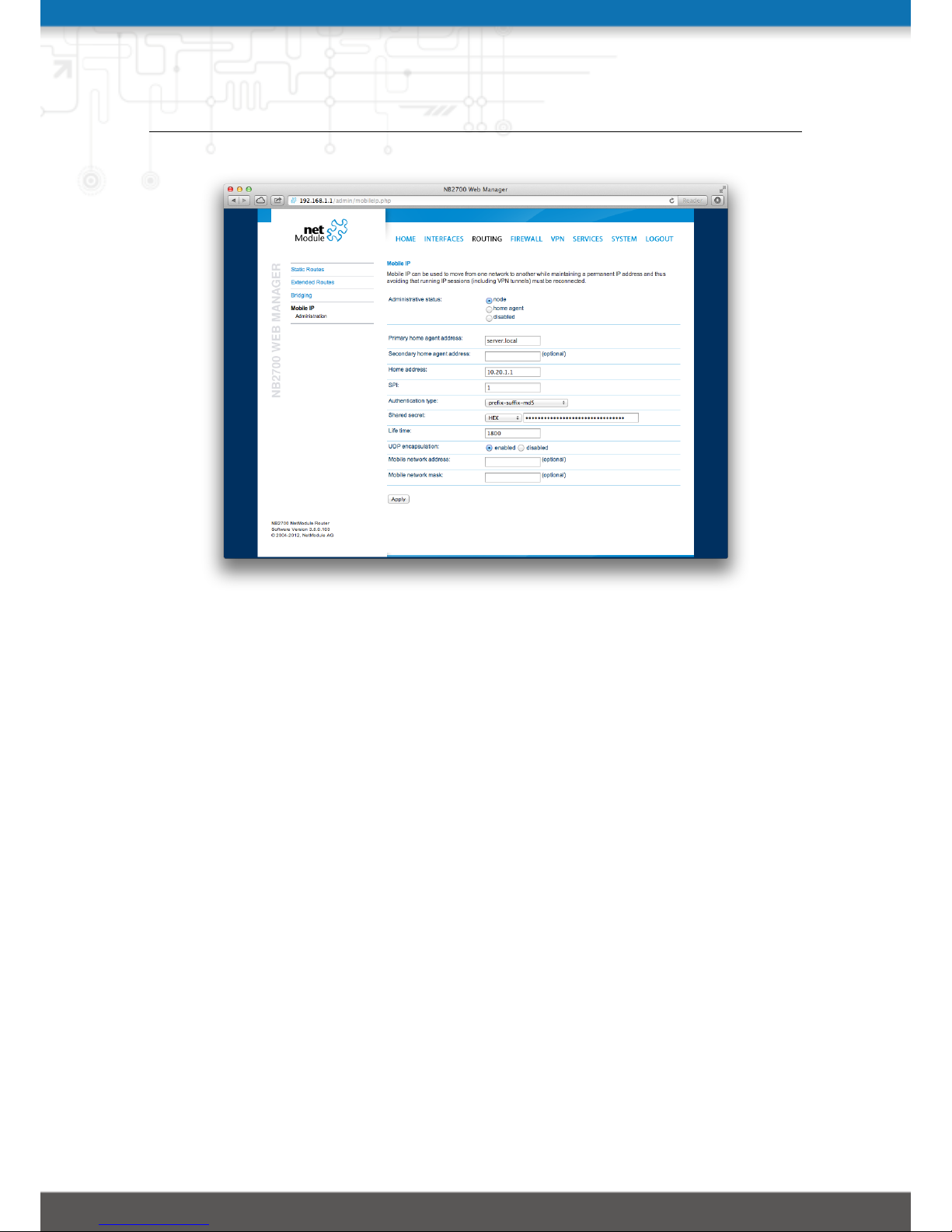
If MIP is run as a mobile node, the following settings can be configured:
Primary home agent address: The address of the primary home agent
Secondary home agent address: The address of the secondary home agent. The mo-
bile node will try to register with this home agent, if the primary home agent is
not reachable.
Home address: The permanent home address of the mobile node which can be used
to reach the mobile router at any time
SPI: The Security Parameter Index (SPI) identifying the security context for the mo-
bile IP tunnel between the mobile node and the home agent. This is used to
distinguish mobile nodes from each other. Therefore each mobile node needs to be
assigned a unique SPI. This is a 32-bit hexadecimal value.
Authentication type: The used authentication algorithm. This can be prefix-suffix-
md5 (default for MIP) or hmac-md5.
52
Page 53
NB2700 User Manual
Figure 5.20.: Mobile IP
Shared secret: The shared secret used for authentication of the mobile node at the
home agent. This can be either a 128-bit hexadecimal value or a random length
ASCII string.
Life time: The lifetime of security associations in seconds
UDP encapsulation: Specifies whether UDP encapsulation shall be used or not. To
allow NAT traversal, UDP encapsulation must be enabled.
Mobile network address: Optionally specifies a subnet which should be routed to the
mobile node. This information is forwarded via Network Mobility (NEMO) extensions to the home agent. The home agent can then automatically add IP routes
to the subnet via the mobile node. Note that this feature is not supported by all
third party home agent implementations.
Mobile network mask: The network mask for the optional routed network
If MIP is run as a home agent, you will have to set up a home address and network
mask for the home agent first. Then you will need to add the configuration for all mobile
nodes, which is made up of the following settings:
SPI: The Security Parameter Index (SPI) identifying the security context for the tunnel
between the mobile node and the home agent. This is used to distinguish mobile
nodes from each other. Therefore each mobile node needs to be assigned a unique
53
Page 54

NB2700 User Manual
SPI. This is a 32-bit hexadecimal value.
Authentication type: The used authentication algorithm. This can be prefix-suffix-
md5 (default for mobile IP) or hmac-md5.
Shared secret: The shared secret used for authentication of the mobile node at the
home agent. This can be either a 128-bit hexadecimal value or a random length
ASCII string.
54
Page 55

NB2700 User Manual
5.5. FIREWALL
5.5.1. Administration
NetModule routers use Linux’s netfilter/iptables firewall framework (see http://www.
netfilter.org for more information) which supports stateful inspection, that is, grant-
ing the same permissions for inherited connections within an IP session (e.g. FTP which
builds up a control and data connection).
The administration page can be used to enable and disable firewalling. When turning it
on, a shortcut can be used to generate a predefined set of rules which allow administration
(over HTTP, HTTPS, SSH or TELNET) by default but block any other packets coming
from the WAN interface.
5.5.2. Rules
In general, the firewall is set up of a range of rules which control each packet’s permission to pass the router. Please note that the rules are processed by order, that means
traversing the list from top to bottom until a matching rule is found. Packets which are
not matching any of the rules configured will be ALLOWED.
Description: A meaningful description about the purpose of this rule
Mode: Specifies whether the packets of this rule should be allowed or denied
Source: The source address of matching packets, can be any or specified by an ad-
dress/network
Destination: The destination address of matching packets, can be any, local (addressed
to the system itself) or specified by an address/network
Incoming interface: The interface on which matching packets are received
Protocol: The used IP protocol of matching packets, can be UDP, TCP or ICMP
Destination port(s): The destination port of matching packets, which can be specified
by a single port or a range of ports (only UDP/TCP)
The statistics page can be used to figure out if rules have matched any packets and
provides a convenient way to debug your firewall setup.
55
Page 56
NB2700 User Manual
5.5.3. NAPT
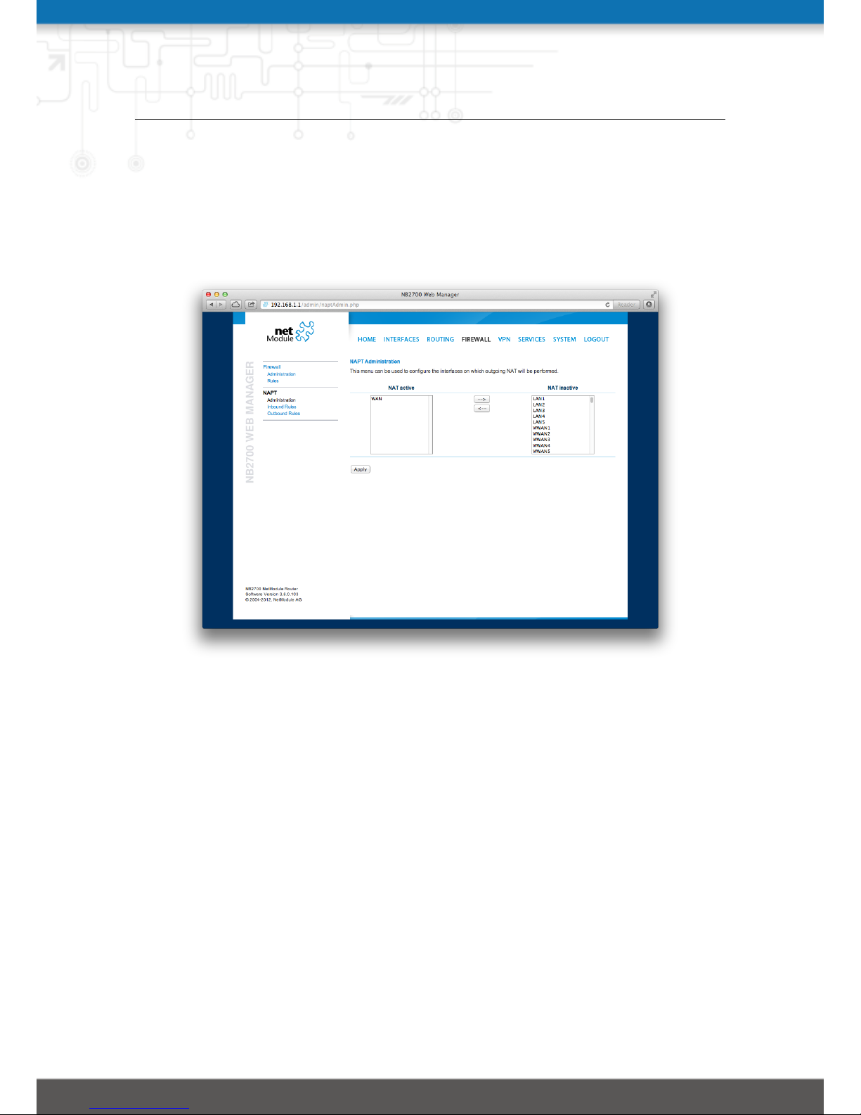
This page can be used to configure Network Address and Port Translation (NAPT) for
packets traversing the system. NAPT hereby modifies IP addresses or/and TCP/UDP
ports in matching IP packets. By tracking those connections, it will also automatically
adjust the returning packets of an IP session.
Figure 5.21.: NAPT Administration
The administration page lets you specify the interfaces on which outgoing NAT (also
called Masquerading) will be performed. NAT will hereby use the address of the selected
interface and choose a random source port for outgoing connections and thus enables
communication between hosts from a private local area network towards hosts on the
public network.
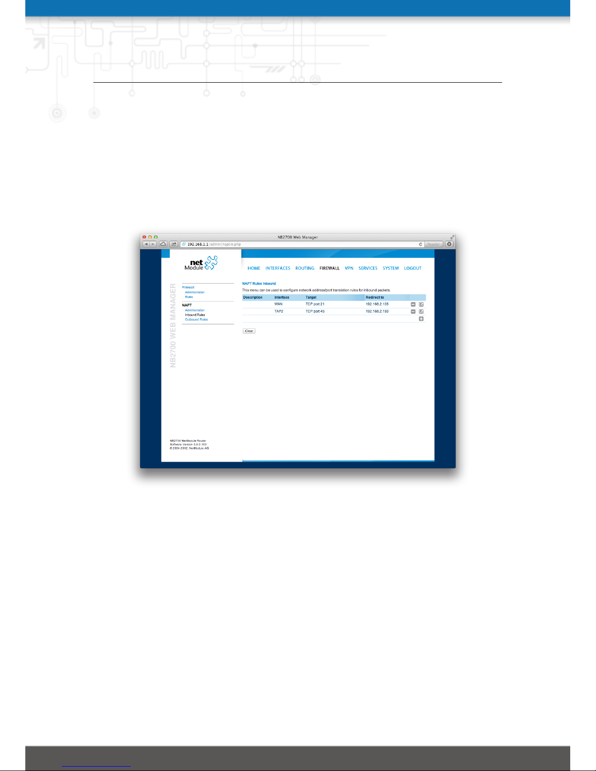
NAPT Inbound Rules
Inbound rules can be used to modify the target section of IP packets and, for instance,
forward a service or port to an internal host. By doing so, you can expose that service
and make it available from the Internet. You may also establish 1:1 NAT mapping for
a single host using additional outbound rules.
Please note that the specified rules are processed by order, that means, traversing the
list from top to bottom until a matching rule is found. If there is no matching rule
found, the packet will pass as is.
56
Page 57
NB2700 User Manual
Description: A meaningful description of this rule
Incoming interface: The interface from which matching packets are received
Target address: The destination address of matching packets (optional)
Protocol: The used protocol of matching packets
Ports: The used UDP/TCP port of matching packets
Redirect to: The address to which matching packets shall be redirected
Redirect port: The port to which matching packets will be redirected
Figure 5.22.: Inbound NAPT
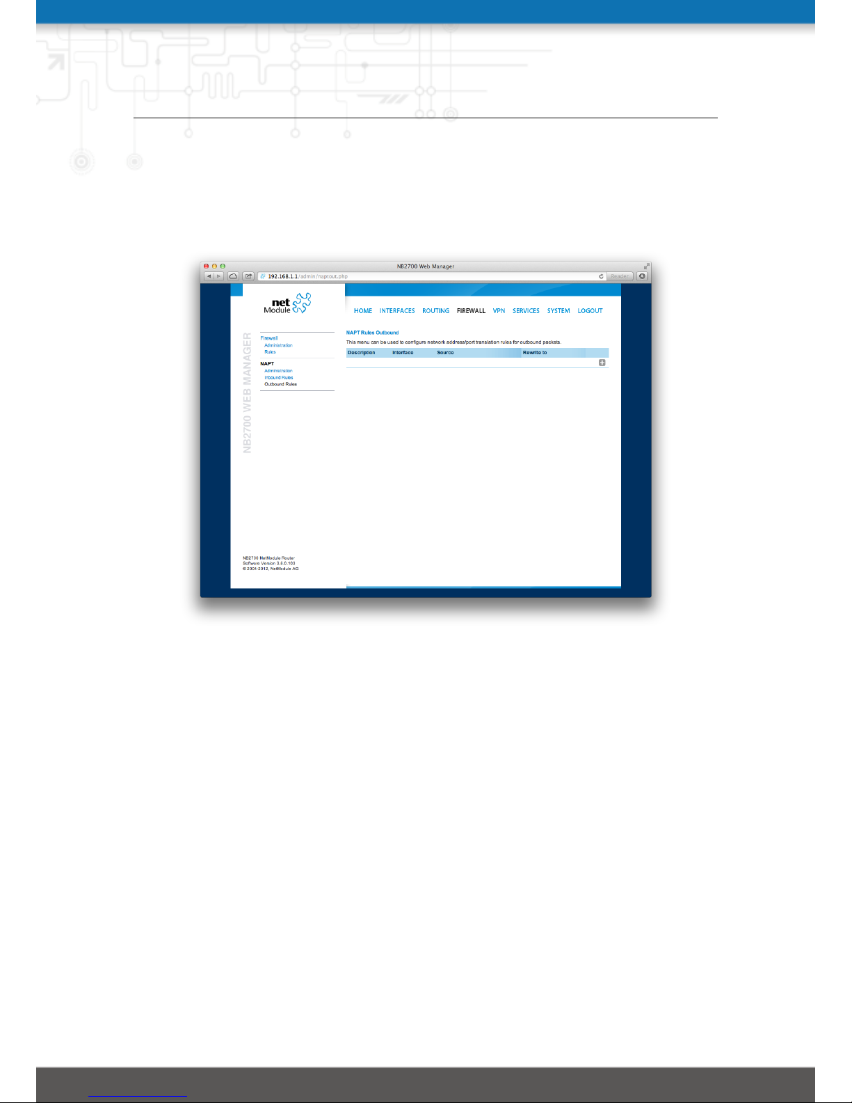
NAPT Outbound Rules
Outbound rules will modify the source section of IP packets and can be used to establish
1:1 NAT mappings but also to redirect packets to a specific service.
Description: A meaningful description of this rule
Incoming interface: The outgoing interface on which matching packets are leaving the
router
Source address: The source address of matching packets (optional)
Protocol: The used protocol of matching packets
Ports: The used UDP/TCP port of matching packets
57
Page 58
NB2700 User Manual
Rewrite source address: The address to which the source address of matching packets
shall be rewritten
Rewrite source port: The port to which the source port of matching packets shall be
rewritten
Figure 5.23.: Outbound NAPT
58
Page 59
NB2700 User Manual
5.6. VPN
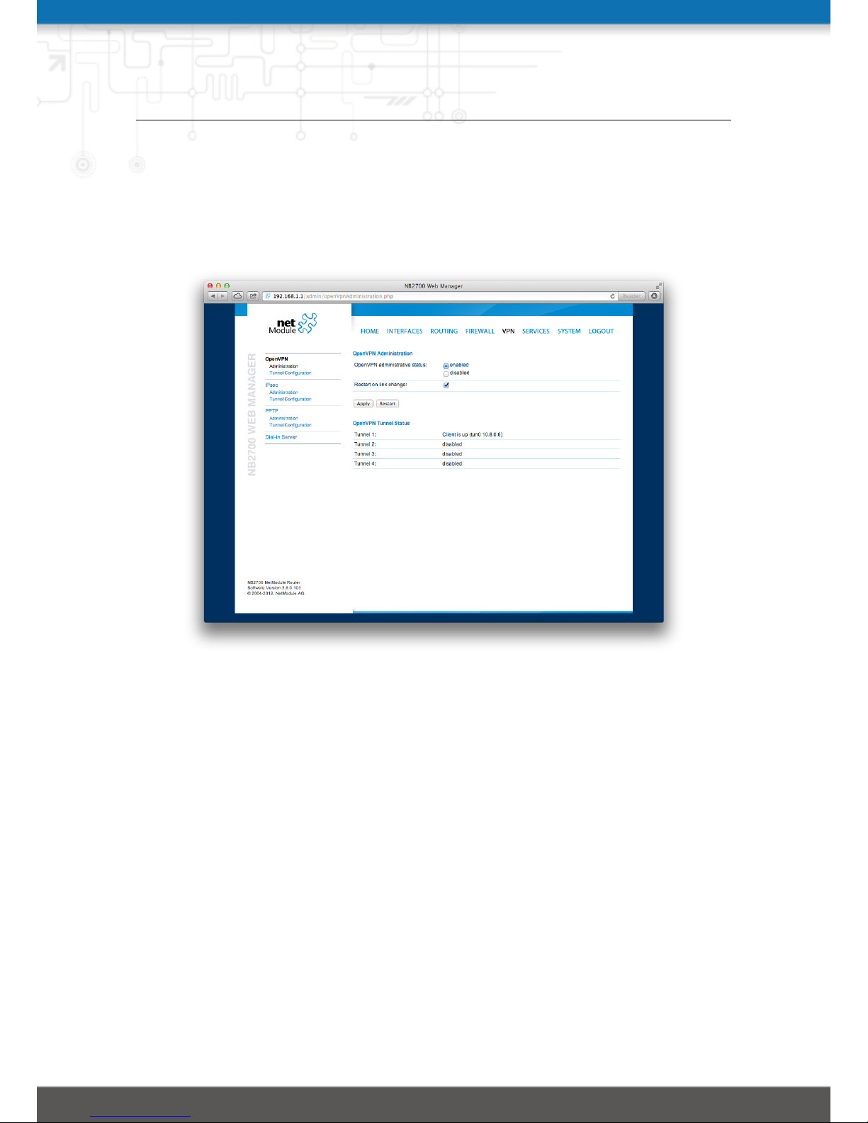
5.6.1. OpenVPN
OpenVPN Administration
Figure 5.24.: OpenVPN Administration
Tunnel Configuration
NetModule routers support one single server tunnel and up to four client tunnels. You
can specify tunnel parameters either in standard configuration or upload an expert mode
file which has been created in advance. Refer to chapter 5.6.1 to learn more about how
to manage clients and generate the files.
If the tunnel is operated in client mode, the following settings can be applied:
Operation mode: Specifies whether client or server mode should be used for this tunnel
Primary server address: The address of the primary server
Primary server port: The port of the primary server (1194 by default)
Secondary server address: The address of the secondary server address (optional) which
will be used in case the primary address cannot be reached
Secondary server port: The port of the secondary server (optional)
59
Page 60

NB2700 User Manual
Setting up a tunnel server just requires the server port to be set, the settings mentioned
below apply for both, server and client tunnels:
Type: The encapsulation type for this tunnel which can be either TUN (typically used
for routed connections) or TAP (needed for bridged networks)
Network mode: Defines how the packets should be forwarded, which can be either
routed or bridged from/to a particular LAN interface
Cipher: The required cipher mechanism used for encryption
Use compression: Enable or disable packet compression
Use keepalive: Can be used to send a periodic keepalive packet in order to keep the
tunnel up despite of inactivity
Redirect gateway: By redirecting the gateway, all packets will be directed to the VPN
tunnel. Please ensure that essential services (such as DNS or NTP servers) can be
reached at the network behind the tunnel. In doubt, create an extra static route
pointing to the correct interface.
Protocol: The tunnel protocol to be used for the transport connection
Authentication: You can choose between no authentication, credential-based (where
you have to specify a username and password) as well as based on keys and certificates. Note that keys/certificates have to be created or uploaded for making the
tunnel work.
ExpertConfiguration
OpenVPN Expert Configuration (Client)
The expert configuration mode offers a straightforward way to configure a tunnel by simply uploading a package containing the required configuration and optionally key/certificate files. A client tunnel usually consists of the following files:
client.conf: OpenVPN configuration file (see http://www.openvpn.net for available
options)
ca.crt: aoot certificate authority file
client.crt: Certificate file
client.key: Private key file
Please note that you may specify arbitrary file names, however, the configuration file
suffix must be .conf and all files referred in the configuration file must correspond to
relative path names.
OpenVPN Expert Configuration (Server) A server tunnel typically requires the following files:
server.conf: OpenVPN configuration file
ca.crt: Root certificate authority file
60
Page 61
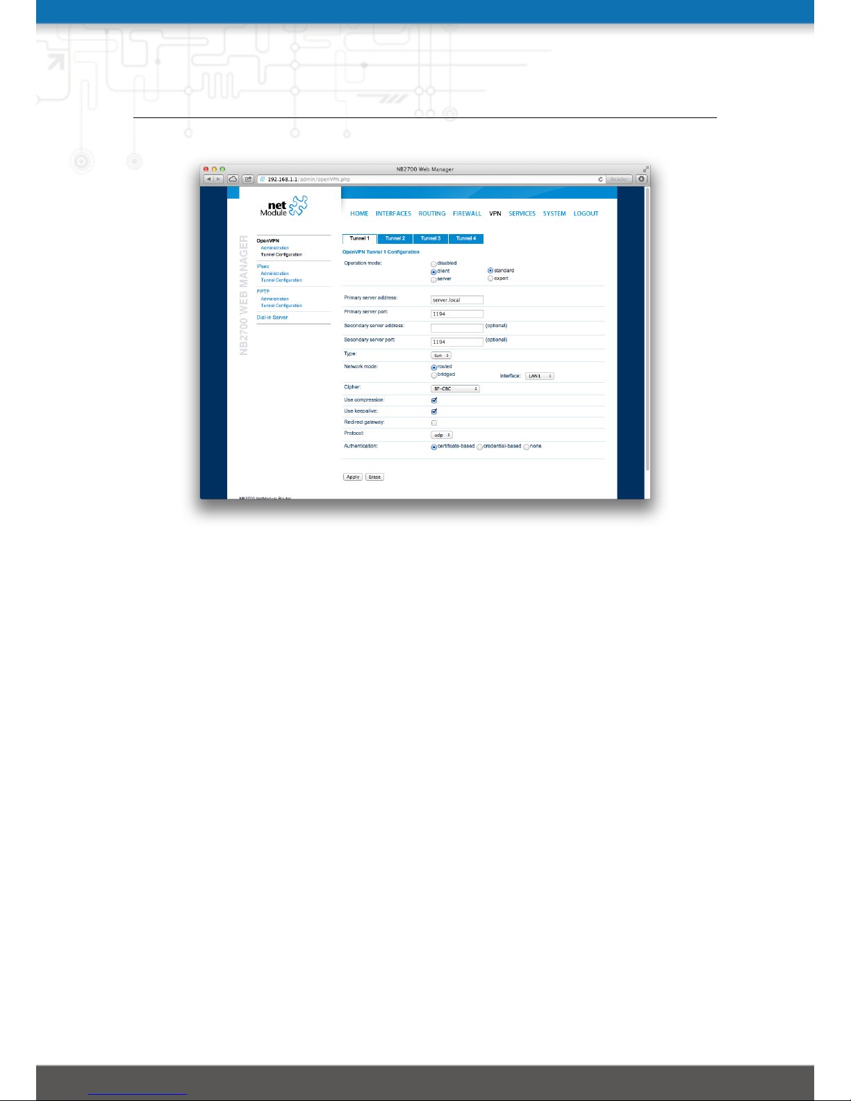
NB2700 User Manual
Figure 5.25.: OpenVPN Configuration
server.crt: Certificate file
server.key: Private key file
dh1024.pem: Diffie-Hellman parameters file
ccd: A directory containing client-specific configuration files
Keep in mind that a certificate becomes valid once its validity time has been reached,
thus an accurate system has to be set prior to creating certificates and establishing a
tunnel connection. Please ensure that all NTP servers are reachable. Using host names
also requires a working DNS server.
Client Management
Once you have successfully set up an OpenVPN server tunnel, you can manage and
enable clients connecting to your service. Currently connected clients can be seen on
this page, including the connect time and IP address. You may kick connected clients
by disabling them.
In the Networking section you can specify a fixed tunnel endpoint address for each client
as well as the network behind it. This can be used for routing purposes.
You may also define further routes to be pushed to each client in case you want to
redirect traffic for particular networks towards the server. Routing between the clients
is generally not allowed but you can enable it if desired.
61
Page 62
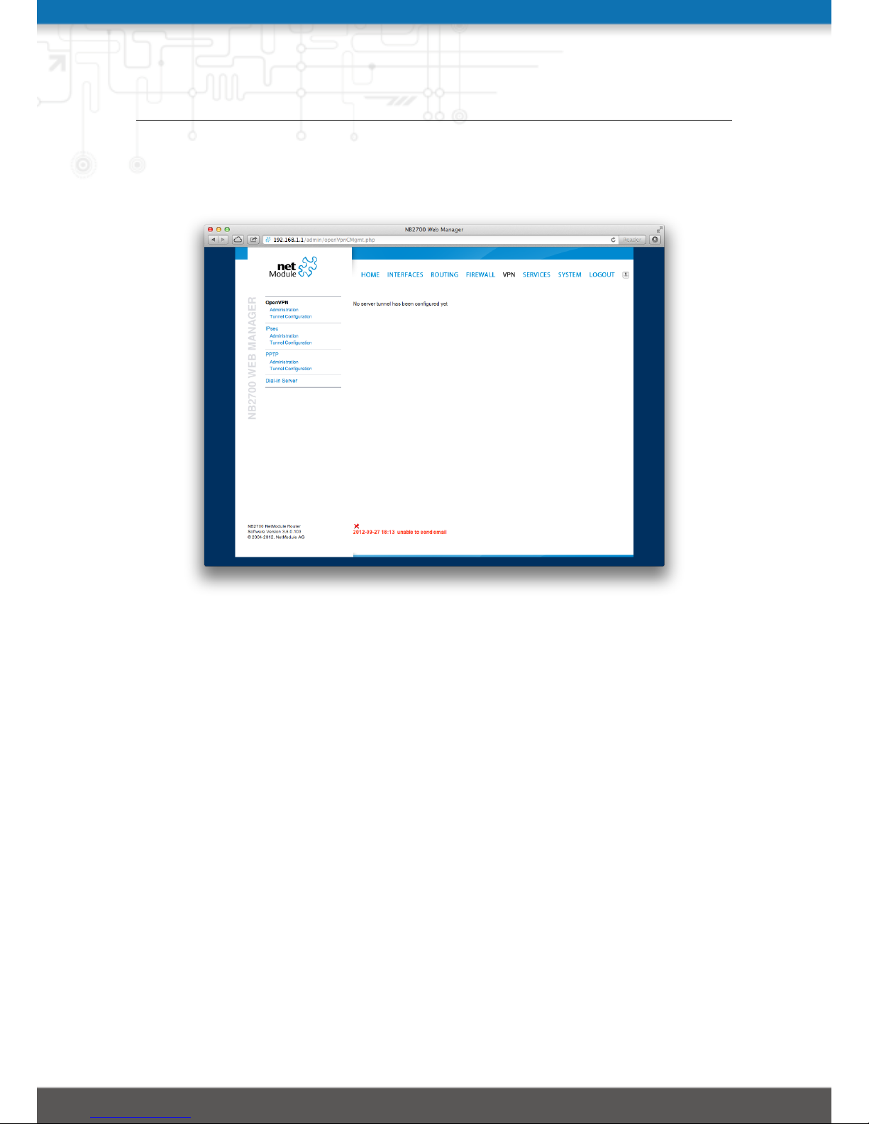
NB2700 User Manual
Finally, you can generate and download all expert mode files for enabled clients which
can be used to easily populate each client.
Figure 5.26.: OpenVPN Client Management
62
Page 63

NB2700 User Manual
5.6.2. IPsec
IPsec is a protocol suite for securing IP communications by authenticating and encrypting each packet of a communication session and thus establishing a secure virtual private
network.
IPsec includes various cryptographic protocols and ciphers for key exchange and data
encryption and can be seen as one of the strongest VPN technologies in terms of security.
It uses the following mechanisms:
Mechanism Description
AH Authentication Headers (AH) provide connectionless in-
tegrity and data origin authentication for IP datagrams and
ensure protection against replay attacks.
ESP Encapsulating Security Payloads (ESP) provide confiden-
tiality, data-origin authentication, connectionless integrity,
an anti-replay service and limited traffic-flow confidentiality.
SA Security Associations (SA) provide a secure channel and a
bundle of algorithms that provide the parameters necessary
to operate the AH and/or ESP operations. The Internet
Security Association Key Management Protocol (ISAKMP)
provides a framework for authenticated key exchange.
Negotating keys for encryption and authentication is generally done by the Internet Key
Exchange protocol (IKE) which consists of two phases:
Phase Description
IKE phase 1 IKE authenticates the peer during this phase for setting up
an ISAKMP secure association. This can be carried out by
either using main or aggressive mode. The main mode approach utilizes the Diffie-Hellman key exchange and authentication is always encrypted with the negotiated key.The
aggressive mode just uses hashes of the pre-shared key and
therefore represents a less-secure mechanism which should
generally be avoided as it is prone to dictionary attacks.
IKE phase 2 IKE finally negotiates IPSec SA parameters and keys and
sets up matching IPSec SAs in the peers which is required
for AH/ESP later on.
63
Page 64
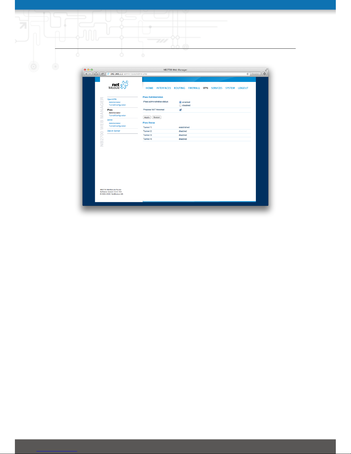
NB2700 User Manual
Figure 5.27.: IPsec Administration
Administration
This page can be used to enable/disable IPsec, you may also specify whether NATTraversal should be used.
NAT-Traversal is mainly used for connections which traverse a path where a router
modifies the IP address/port of packets. It encapsulates packets in UDP and therefore
requires a slight overhead which has to be taken into account when running over smallsized MTU interfaces.
Please note that running NAT-Traversal makes IKE using UDP port 4500 rather than
500 which has to be taken into account when setting up firewall rules.
General
For setting up the tunnel you will have to configure the following parameters first:
Remote peer: IP address or host name of the remote IPsec peer (aka responder or
server)
DPD Status: Specifies whether Dead Peer Detection (see RFC 3706) shall be used.
DPD will detect any broken IPSec connections, in particular the ISAKMP tunnel, and refresh the corresponding SAs (Security Associations) and SPIs (Security
Payload Identifier) for a faster re-establishment of the tunnel.
Detection cycle): The delay (in seconds) between DPD keepalives that are sent for this
64
Page 65
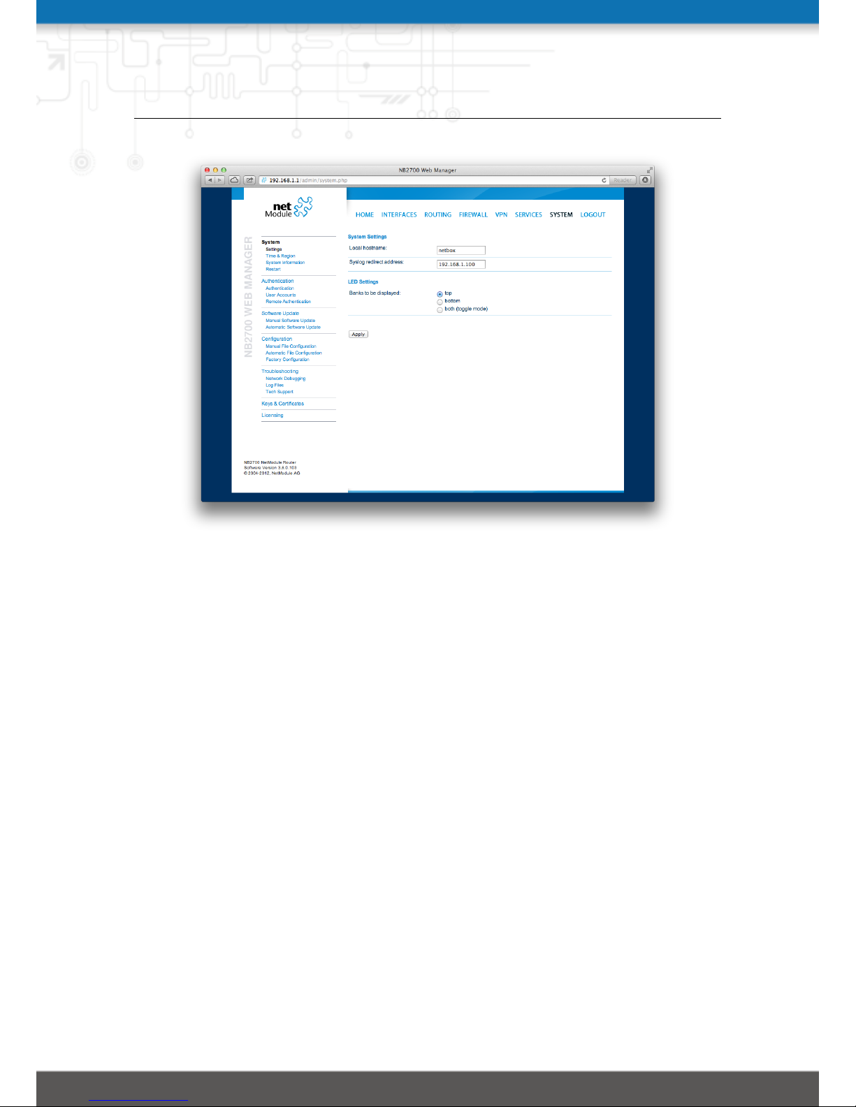
NB2700 User Manual
Figure 5.28.: IPsec Configuration
connection (default 30 seconds)
Failure threshold: The number of unanswered DPD requests until the IPsec peer is
considered dead (the router will then try to re-establish a dead connection automatically)
IKE Authentication
NetModule routers support IKE authentication through pre-shared keys (PSK) or certificates within a public key infrastructure.
Using PSK requires the following settings:
PSK: The pre-shared key used to authenticate at the peer
Local ID Type: The type of identification for the local ID which can be a FQDN, username@FQDN
or IP address
Local ID: The local ID value
Local ID Type: The type of identification for the remote ID
Remote ID: The remote ID value
When using certificates you would need to specify the operation mode. When run as
PKI client you can create a Certificate Signing Request (CSR) in the certificates section
which needs to be submitted at your Certificate Authority and imported to the router
65
Page 66

NB2700 User Manual
afterwards. In PKI server mode the router represents the Certificate Authority and
issues the certificates for remote peers.
IKE Proposal
This section can be used to configure the phase 1 settings:
Negotiation mode: Choose the desired negotiation mode. Preferably, main mode should
be used but aggressive mode might be applicable when dealing with dynamic
endpoint addresses.
Encryption algorithm: The desired IKE encryption method (we recommend AES256)
Authentication algorithm: The desired IKE authentication method (we prefer SHA1
over MD5)
IKE Diffie-Hellman Group: The IKE Diffie-Hellman Group
SA life time: The lifetime of Security Associations
Perfect Forward Secrecy: Specifies whether Perfect Forward Secrecy (PFS) should be
used. This feature increases security as PFS avoids penetration of the key-exchange
protocol and prevents compromisation of previous keys.
IPsec Proposal
This section can be used to configure the phase 2 settings:
Encapsulation mode: The desired encapsulation mode (Tunnel or Transport)
IPsec protocol: The desired IPsec protocol (AH or ESP)
Encryption algorithm: The desired IKE encryption method (we recommend AES256)
Authentication algorithm: The desired IKE authentication method (we prefer SHA1
over MD5)
SA life time: The lifetime of Security Associations
Networks
When creating Security Associations, IPsec will keep track of routed networks within
the tunnel. Packets will be only transmitted when a valid SA with matching source and
destination network is present. Therefore, you may need to specify the networks right
and left of the endpoints by applying the following settings:
Local network address: The address of your local area network
Local network mask: The netmask of your local area network
Peer network address: The address of the remote network behind the peer
Peer network mask: The netmask of the remote network behind the peer
NAT address: Optionally, you can apply NAT (masquerading) for packets coming from
a different local network. The NAT address must reside in the network previously
specified as local network.
66
Page 67
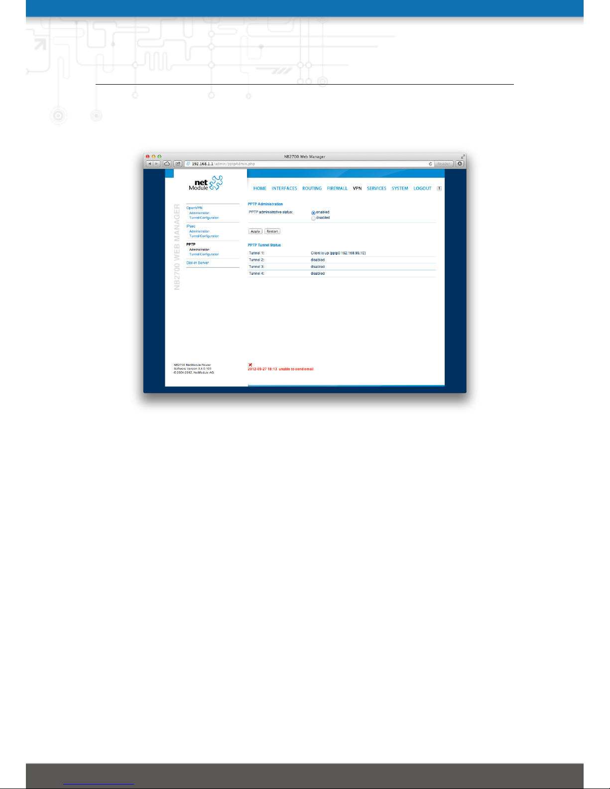
NB2700 User Manual
5.6.3. PPTP
Figure 5.29.: PPTP Administration
The Point-to-Point Tunneling Protocol (PPTP) is a method for implementing virtual
private networks between two hosts. PPTP is easy to configure and widely deployed
amongst Microsoft Dial-up networking servers. However, due to its weak encryption
algorithms, it is nowadays considered insecure but it still provides a straightforward way
for establishing tunnels.
When setting up a PPTP tunnel, you would need to choose between server or client. A
client tunnel requires the following parameters to be set:
Server address: The address of the remote server
Username: The user-name used for authentication
Password: The password used for authentication
Setting up a server requires the following settings:
Listen address: Specifies on which IP address should be listened for incoming client
connections
Server address: The server address within the tunnel
Client address range: Specifies a range of IP addresses assigned to each client
67
Page 68
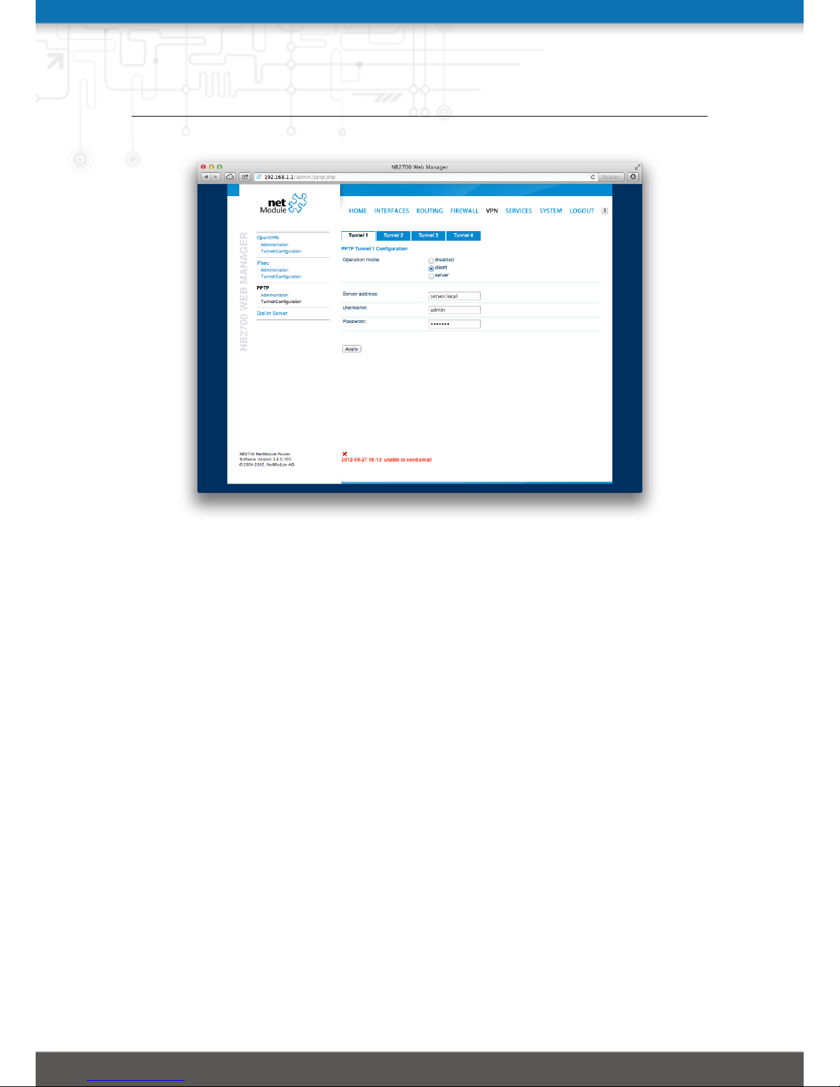
NB2700 User Manual
Figure 5.30.: PPTP Tunnel Configuration
PPTP Client Management
PPTP clients for a server tunnel need to be configured here. They are made up of username and password. A fixed IP address can be assigned to them which can be used to
point any routes to a dedicated tunnel.
68
Page 69
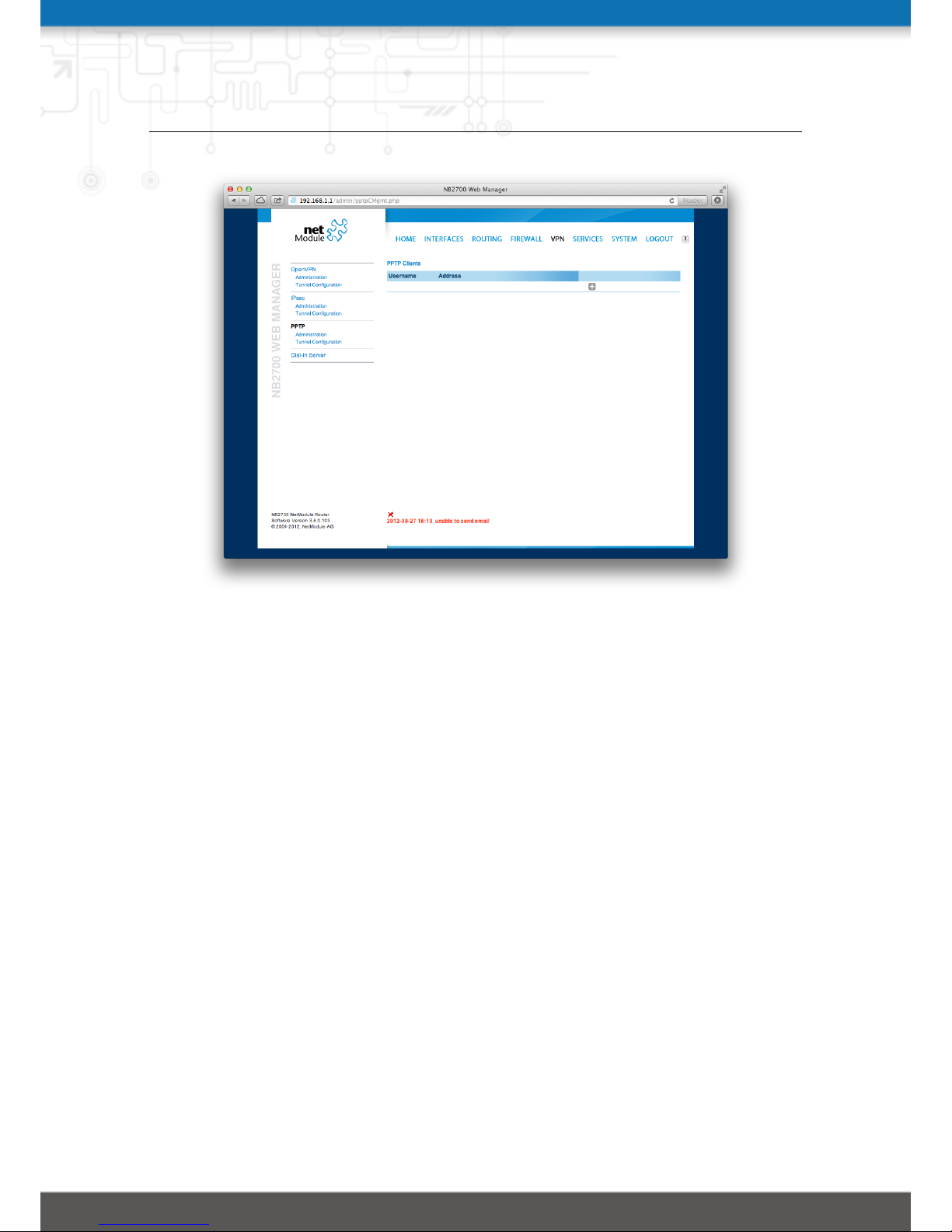
NB2700 User Manual
Figure 5.31.: PPTP Client Management
5.6.4. Dial-In
On this page you can configure the Dial-In server in order to establish a data connection
over GSM calls. Thus, one would generally apply a required service type of 2G-only, so
that the modem registers to GSM only. Naturally, a concurrent use of outgoing WWAN
interfaces and Dial-In connection is not possible.
The following settings can be set:
Administrative status: Specifies whether incoming calls shall be answered or not
Modem: Specifies the modem on which calls can come in
Address range start: Start of the IP address range assigned to incoming clients
Address range size: Number of addresses for client IP address range
Besides the admin account you can configure further users in the user accounts section
which shall be allowed to dial-in.
Please note that Dial-In connections are generally discouraged. As they are implemented
as GSM voice calls, they suffer from unreliability and poor bandwidth.
69
Page 70
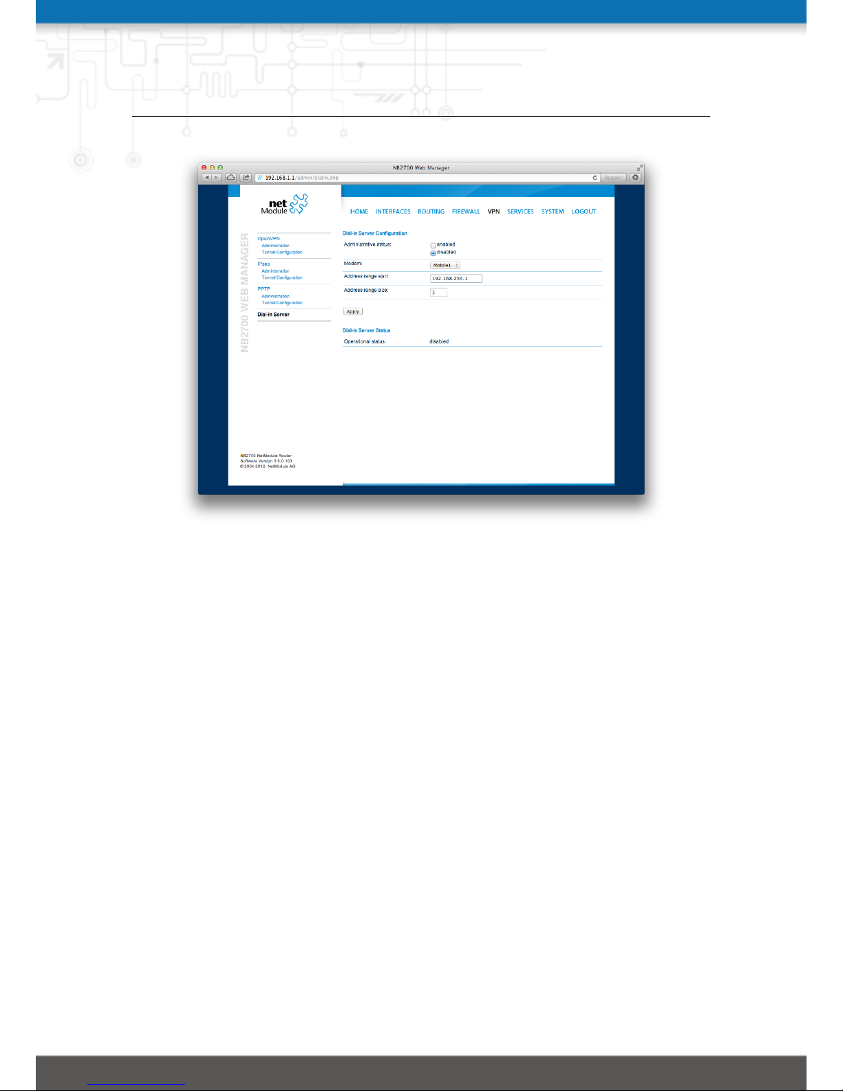
NB2700 User Manual
Figure 5.32.: Dial-in Server Settings
5.7. SERVICES
5.7.1. SDK
NetModule routers are shipping with a Software Development Kit (SDK) which offers
a simple and fast way to implement customer-specific functions and applications. It
consists of:
1. An SDK host which defines the runtime environment (a so-called sandbox), that
is, controlling access to system resources (such as memory, storage and CPU) and,
by doing so, catering for the right scalability
2. An interpreter language called arena, a light-weight scripting language optimized
for embedded systems, which uses a syntax similar to ANSI-C but adds support
for exceptions, automatic memory management and runtime polymorphism on top
of that
3. A NetModule-specific Application Programming Interface (API), which ships with
a comprehensive set of functions for accessing hardware interfaces (e.g. digital IO
ports, GPS, external storage media, serial ports) but also for retrieving system
status parameters, sending E-Mail or SMS messages or simply just to configure
the router
70
Page 71

NB2700 User Manual
Anyone, reasonably experienced in the C language, will find an environment that is easy
to dig in. However, feel free to contact us via [email protected] and we
will happily support you in finding a programming solution to your specific problem.
The Language
The arena scripting language offers a broad range of POSIX functions (like printf
or open) and provides, together with tailor-made API functions, a simple platform for
implementing any sort of applications to interconnect your favourite device or service
with the router.
Here comes a short example:
71
Page 72

NB2700 User Manual
/* We a re g oin g to eav e sd r op on the firs t s e ria l po r t
* and turn on li g hts via a dig i ta l I/ O out p ut po r t ,
* o t he r wi s e w e ' d ha v e to send a sho r t m e ss a ge .
*/
f o r ( a t te m pt s = 0; a tt e mp t s < 3 ; at t em p ts + + ) {
if ( n b _s e ri al _ re a d ( " s er i al0 " ) == " Kn o ck Knoc k ! " ) {
nb _ se ri a l_ w r i te ( " ser ial 0 " , " Who 's ther e ? ") ;
if ( nb _s e ri al _ re a d ( " s er i al0 " ) == " Sa n ta " ) {
pri n tf ( " H ur r ay !\ n" );
nb _ di o _s e t ( " o u t1 " , 1 ) ;
}
}
}
nb _ sm s _s e nd ( " +1 2 34 567 89 " , "No pre s en t s this year :( " )
A set of example scripts can be downloaded directly from the router, you can find a list
of them in the appendix. The manual at http://www.netmodule.com/store/sdk gives a
detailed introduction of the language, including a description of all available functions.
SDK API Functions
The current range of API functions can be used to implement the following features:
1. Send/Retrieve SMS
2. Send E-mail
3. Read/Write from/to serial device
4. Control digital input/output ports
5. Run TCP/UDP servers
6. Run IP/TCP/UDP clients
7. Access files of mounted media (e.g. an USB stick)
8. Retrieve status information from the system
9. Get or set configuration parameters
10. Write to syslog
11. Transfer files over HTTP/FTP
12. Get system events / Reboot system
13. Control the LEDs
The SDK API manual at http://www.netmodule.com/store/sdk provides an overview
but also explains all functions in detail.
72
Page 73
NB2700 User Manual
Please note that some functions require the corresponding services (e.g. E-Mail, SMS)
to be properly configured prior to utilizing them in the SDK.
Let’s now pay some attention to the very powerful API function nb_status. It can
be used to query the router’s status values in the same manner as they can be shown
with the CLI. It returns a structure of variables for a specific section (a list of available
sections can be obtained by running cli status -h).
By using the dump function you can figure out the content of the returned structure:
/* d u mp cur r ent l o cat ion */
dump ( n b _s t at u s ( " l oc a ti o n ") );
The script will then generate lines like maybe these:
struct(8): {
.LOCATION_STREET = string[11]: "Bahnhofquai"
.LOCATION_CITY = string[10]: "Zurich"
.LOCATION_COUNTRY_CODE = string[2]: "ch"
.LOCATION_COUNTRY = string[11]: "Switzerland"
.LOCATION_POSTCODE = string[4]: "8001"
.LOCATION_STATE = string[6]: "Zurich"
.LOCATION_LATITUDE = string[9]: "47.3778058"
.LOCATION_LONGITUDE = string[8]: "8.5412757"
}
In combination with the nb_config_set function, it is possible to start a re-configuration
of any parts of the system upon status changes. You may query possible sections and
parameters again with the CLI:
~ $ cli get -c wanlink.0
Showing configuration sections (matching ’wanlink.0’):
wanlink.0.mode
wanlink.0.name
wanlink.0.prio
wanlink.0.weight
Running the CLI in interactive mode, you will be also able to step through possible
configuration parameters by the help of the TAB key.
73
Page 74
NB2700 User Manual
Here is an example how one might adopt those functions:
/* c h eck cu r re n t ci ty an d e n abl e the se c ond WAN li nk * /
lo c ati on = nb_ sta tus ( " lo c at i on " ) ;
if ( lo c at i on ) {
city = st r uc t _g et ( lo c a tion , " L OC A TI O N_ CI T Y " ) ;
if ( city == " Wo n de r la nd " ) {
f o r ( led = 0; led < 5; led ++) {
nb _ le d _s e t ( l ed , L ED _ BL I N K _F A ST | L ED _ C O LO R _R E D ) ;
}
} e l s e {
pri n tf ( " Y o u 'll neve r wa l k a lon e in % s ...\ n " , c i ty );
nb _ co n f i g_ s et ( " wa n lin k .1. m ode =1 " ) ;
}
}
Running SDK
In the SDK, we are speaking of scripts and triggers which form jobs.
Any arena script can be uploaded to the router or imported by using dedicated user
configuration packages. You may also edit the script directly at the Web Manager or
select one of our examples. You will further have a testing section on the router which
can be used to check your syntax or doing test runs.
Once uploaded, you will have to specify a trigger, that is, telling the router when the
script is to be executed. This can be either time-based (e.g. each Monday) or triggered by
one of the pre-defined system events (e.g. wan-up) as described in Events chapter 5.7.6.
With both, a script and a trigger, you can finally set up an SDK job now. The test
event usually serves as a good facility to check whether your job is doing well. The
admin section also offers facilities to troubleshoot any issues and control running jobs.
The SDK host (sdkhost) corresponds to the daemon managing the scripts and their
operations and thus avoiding any harm to the system. In terms of resources, it will
limit CPU and memory for running scripts and also provide a pre-defined portion of
the available flash storage. You may, however, extend it by external USB storage or
(depending on your model) SD cards.
Files written to /tmp will be hold in memory and will be cleared upon a restart of the
script. As your scripts operate in the sandbox, you will have no access to tools on the
system (such as ifconfig).
74
Page 75
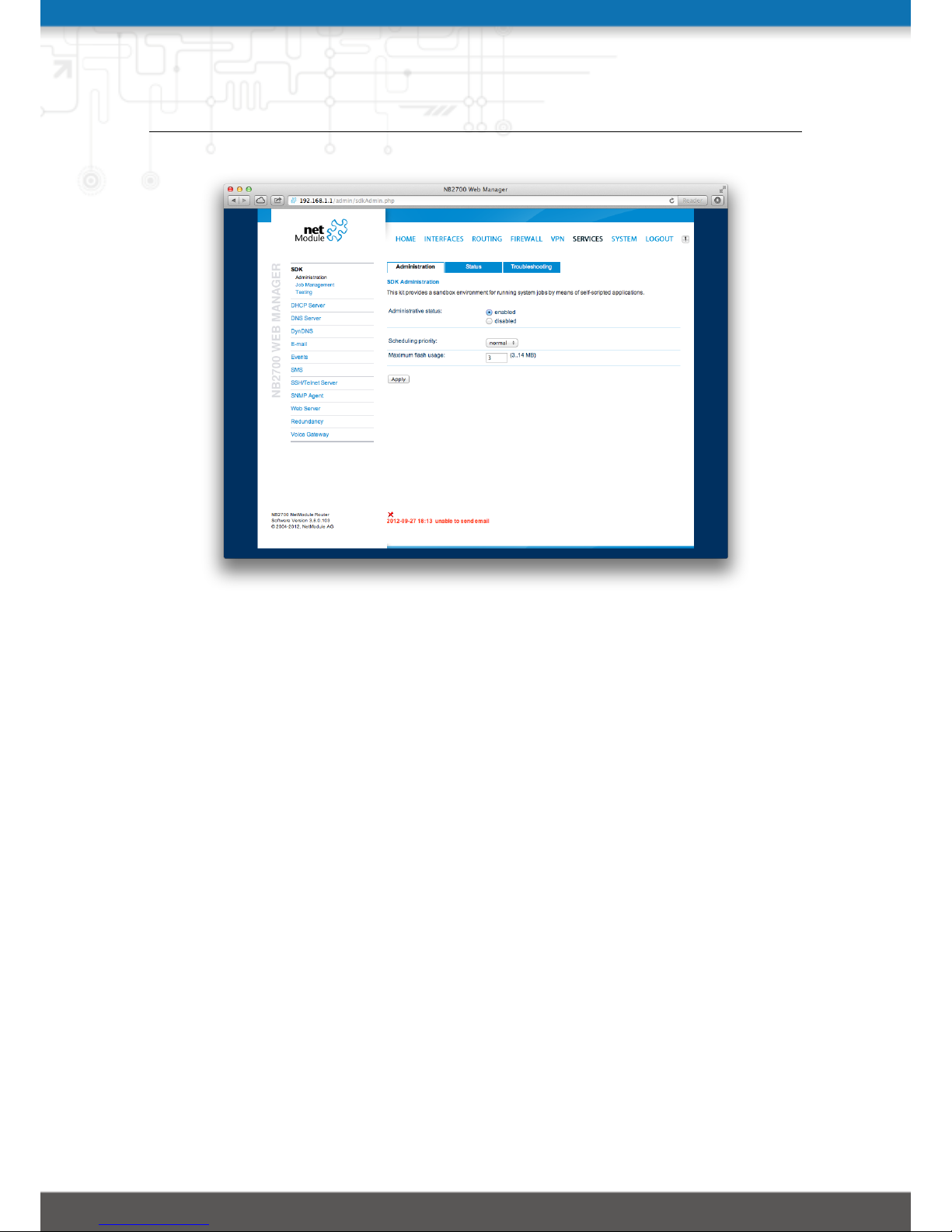
NB2700 User Manual
Figure 5.33.: SDK Administration
Administration
This page can be used to control the SDK host and apply the following settings:
Parameter: Description
Administrative status: Specifies whether SDK scripts should run or not
Scheduling priority: Specifies the process priority of the sdkhost, higher priorities will
speed up scheduling your scripts, lower ones will have less impact to the host
system
Maximum flash usage: The maximum amount of MBytes your scripts can write to the
internal flash
The status page informs you about the current status of the SDK. It provides an overview
about any finished jobs, you can also stop a running job there and view the script output
in the troubleshooting section where you will also find links for downloading the manuals
and examples.
Job Management
This page can be used to set up scripts, triggers and jobs. It is usually a good idea to
create a trigger first which is made up by the following parameters:
Name: A meaningful name to identify the trigger
75
Page 76

NB2700 User Manual
Type: The type of the trigger, either time-based or event-based
Condition: Specifies the time condition for time-based triggers (e.g. hourly)
Timespec: The time specification which, together with the condition, specifies the
time(s) when the trigger should be pulled
Event: The system event upon which the trigger should be pulled
You can now add your personal script to the system by applying the following parame-
ters:
Name: A meaningful name to identify the script
Description: An optional description of the script
Arguments: An optional set of arguments passed to the script (supports quoting)
Action: You may either edit a script, upload it to the system or select one of the example
scripts or an already uploaded script
You are ready to set up a job afterwards, it can be created by using the following
parameters:
Name: A meaningful name to identify the job
Trigger: Specifies the trigger that should launch the job
Script: Specifies the script to be executed
Arguments: Defines arguments which can be passed to the script (supports quoting),
they will precede the arguments you formerly may have assigned to the script itself
Testing
The testing page offers an editor and an input field for optional arguments which can be
used to perform test runs of your script or test dedicated portions of it. Please note that
you might need to quote arguments as they will otherwise be separated by white-spaces.
/* a rg u me n ts : ' s c hni c k sch n ac k "s c h n u c k" '
for ( i = 0; i < ar g c ; i + + ) {
pri n tf (" a rgv % d : %s \n ", a rgv [ i ]) ;
}
/* g en e ra t es :
* ar g v0 : s cr i pt n am e
* ar g v1 : s chn i ck
* ar g v2 : s chn a ck
* ar g v3 : s c h n u c k
*/
In case of syntax errors, arena will usually print error messages as follows (indicating
the line and position where the parsing error occurred):
76
Page 77
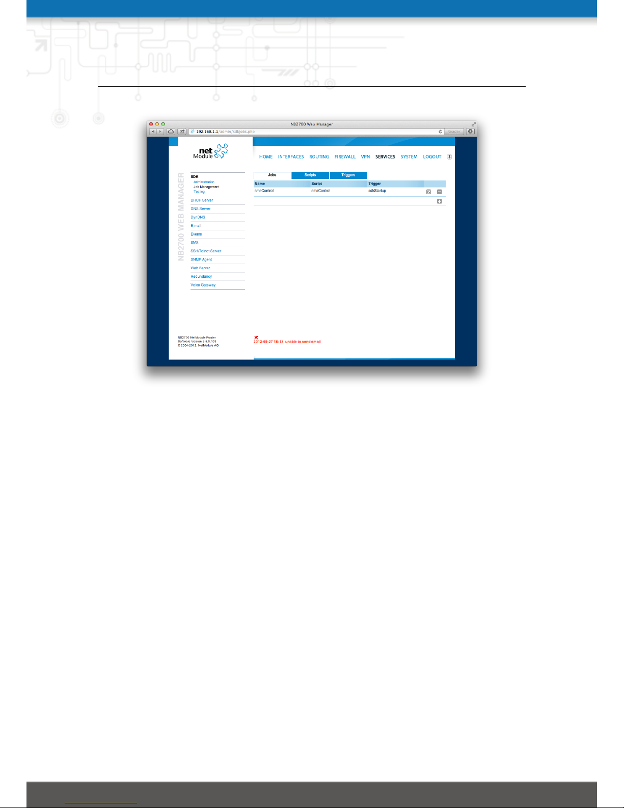
NB2700 User Manual
Figure 5.34.: SDK Jobs
/scripts/testrun:2:10:FATAL: parse error, unexpected $, expecting ’;’
SDK Sample Application
As an introduction, you can step through a sample application, namely the SMS control
script, which implements remote control over short messages and can be used to send a
status of the system back to the sender. The source code is listed in the appendix.
Once enabled, you can send a message to the phone number associated with a SIM /
modem. It generally requires a password to be given on the first line and a command
on the second, such as:
admin01
status
We strongly recommend to use authentication in order to avoid any unintended access,
however you may pass noauth as argument to disable it. You can then skip the first line
containing the password. Having a closer look to the script, you will see that you will
also be able to restrict the list of permitted senders. Please inspect the system log for
troubleshooting any issues.
The following commands are supported:
77
Page 78
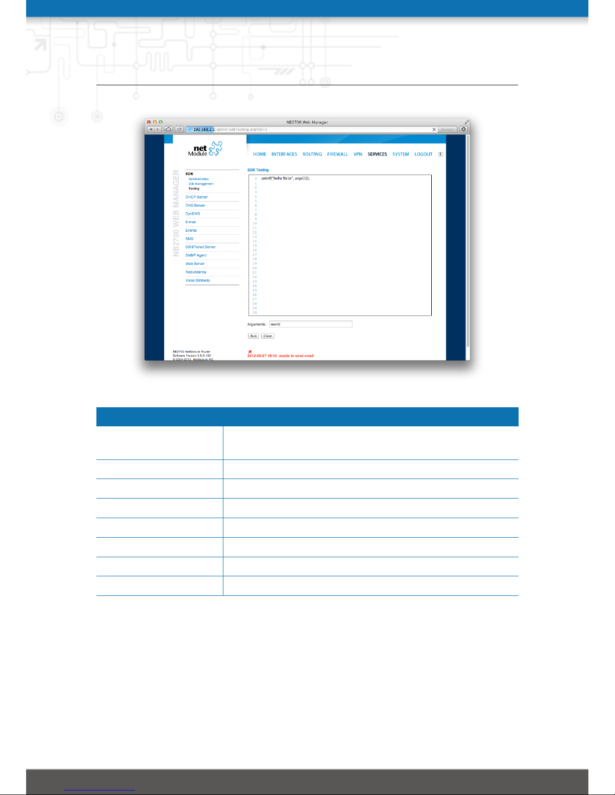
NB2700 User Manual
Figure 5.35.: SDK Testing
Command Action
status Will reply a message to the sender including a short system
overview
connect Will enable the first WAN link configured on the system
disconnect Will disable the first WAN link configured on the system
reboot Initiates a reboot of the system
output 1 on Turns on the first digital output port
output 1 off Turns off the first digital output port
output 2 on Turns on the second digital output port
output 2 off Turns off the second digital output port
Table 5.5.: SMS Control Commands
A response to the status command typically looks like:
System: NB2700 hostname (00:11:22:AA:BB:CC)
WAN1: WWAN1 is up (10.0.0.1, Mobile1, UMTS, -83 dBm, LAI 12345)
GPS: lat 47.377894, lon 8.540055, alt 282.200
OVPN: client on tun0 is up (10.0.8.4)
DIO: IN1=off, IN2=off, OUT1=on, OUT2=off
78
Page 79
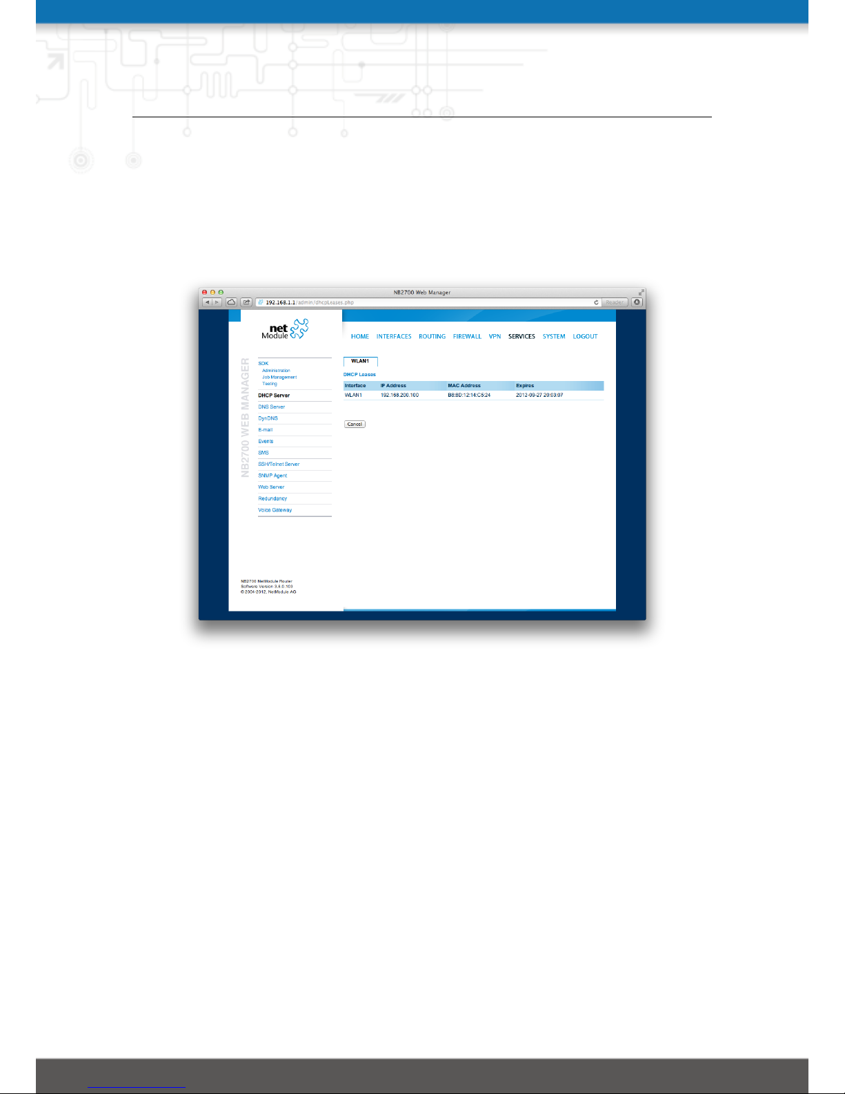
NB2700 User Manual
5.7.2. DHCP Server
This section can be used to individually configure the Dynamic Host Configuration
Protocol (DHCP) service for each LAN interface which will serve dynamic IP addresses
to hosts in the local network. You may also have a look to the leases page where you
can find an overview about negotiated client addresses.
Figure 5.36.: DHCP Leases
Please note that WLAN interfaces (for each SSID) will pop up here as well in case you
have configured an access point respectively.
The following settings for each interface can be applied then:
Administrative status: Specifies whether the DHCP server is enabled or not
First lease address: The first address out of the range of IP addresses given to hosts
Last lease address: The last address out of this range
Lease duration: Number of seconds how long a given lease shall be valid until it has to
be requested again
Persistent leases: By turning on this option the router will remember issued leases
even after a reboot. This can be used to ensure that the same IP address will be
assigned to a particular host.
DHCP options: By default the DHCP will hand out the interface address as default
79
Page 80
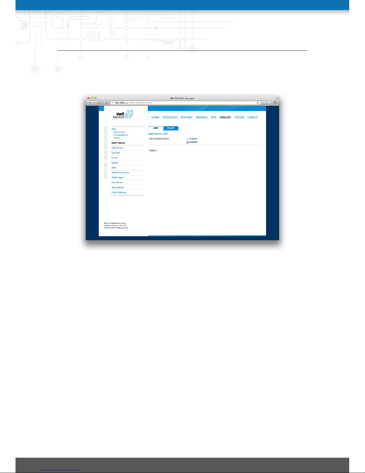
NB2700 User Manual
gateway and the current DNS server addresses if not configured elsewise. You can
specify fixed addresses here.
Figure 5.37.: DHCP Server
80
Page 81
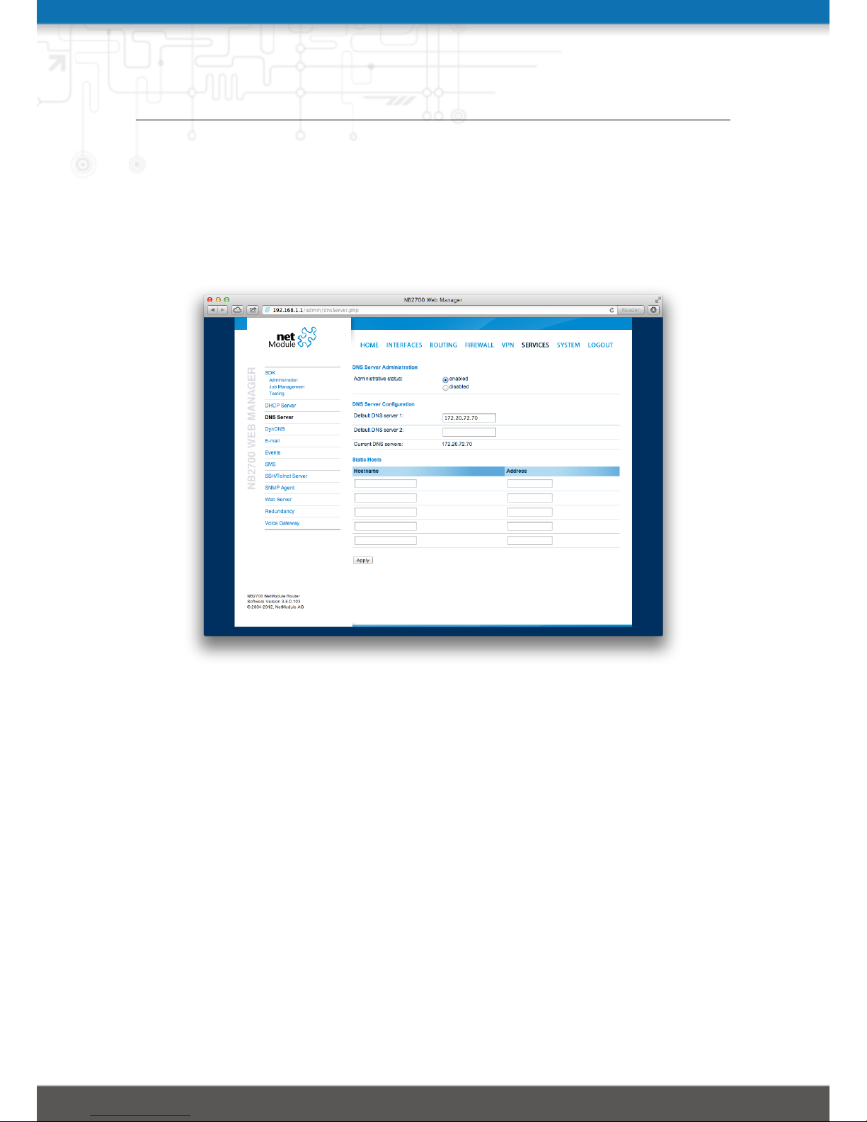
NB2700 User Manual
5.7.3. DNS Server
The DNS server can be used to proxy DNS requests towards servers on the net which have
for instance been negotiated during WAN link negotiation. By pointing DNS requests to
the router, one can reduce outbound DNS traffic as it is caching already resolved names
but it can be also used for serving fixed addresses for particular host names.
Figure 5.38.: DNS Server
The following settings can be applied:
Administrative status: Enables or disables the DNS server
Default DNS server 1: The primary default DNS server which will be used if no other
service can be negotiated
Default DNS server 2: The secondary server which will be used in case the primary
server is not available
You may further configure static hosts for serving fixed IP addresses for various hostnames. Please remember to point local hosts to the router’s address for resolving them.
81
Page 82
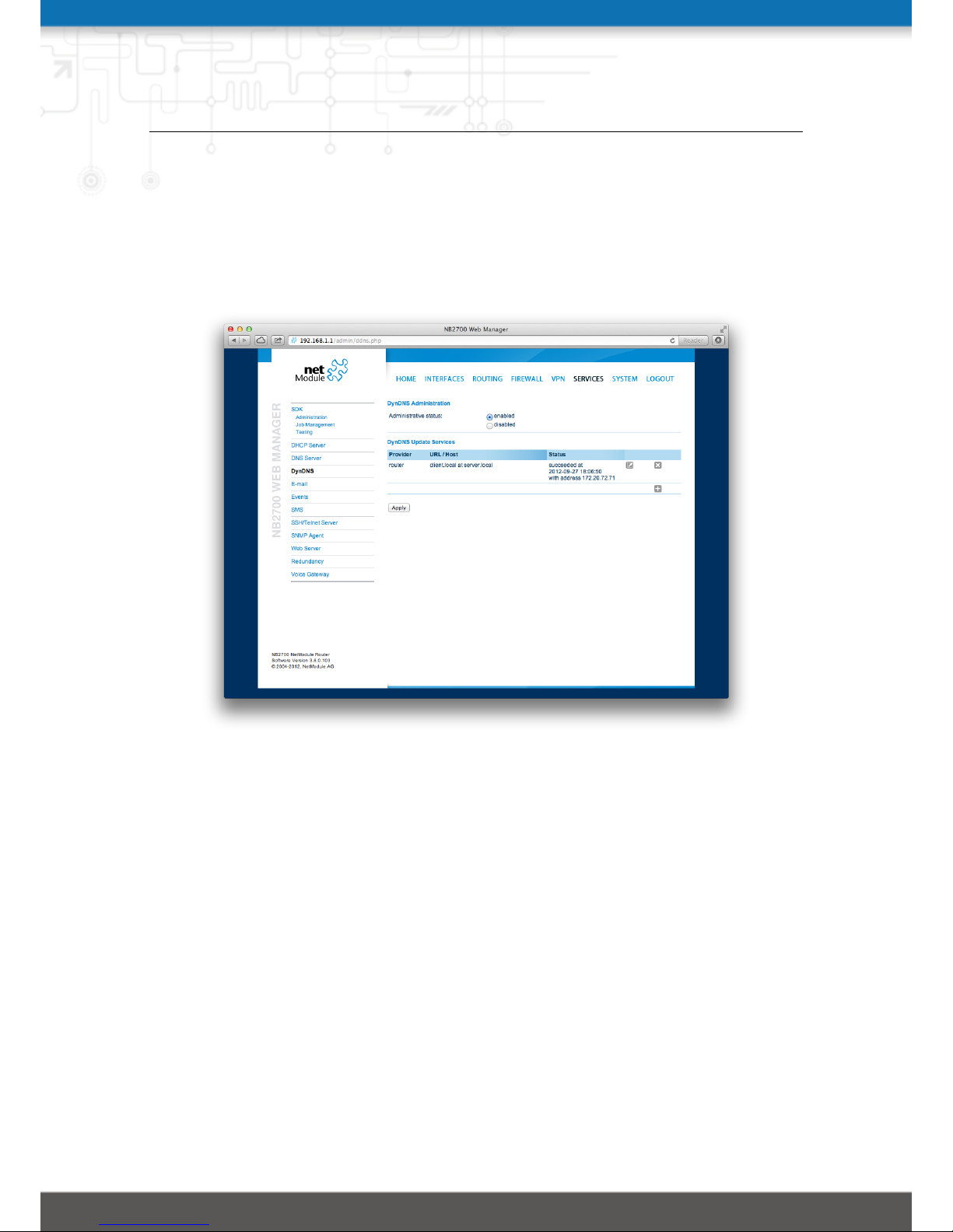
NB2700 User Manual
5.7.4. DynDNS
The dynamic DNS client on this box can be used to tell one or more DynDNS providers
the current WAN address of this system. This address can be either derived from the
current hot-link address or by querying an HTTP service in the Internet for the current
Internet address. The latter might be applicable in NAT scenarios.
Figure 5.39.: Dynamic DNS Settings
Each service can be configured as follows:
Provider: You can choose one of the listed providers or provide a custom URL
Dynamic address: Specifies whether the address is derived from the hot-link or via an
external service
Hostname: The host-name provided by your DynDNS service (e.g. mybox.dyndns.org)
Port: The HTTP port of the service (typically 80)
Username: The user-name used for authenticating at the service
Password: The password used for authentication
Please note that your NetModule router can operate as DynDNS service as well, provided
that you hold a valid SERVER license and have your hosts pointed to the DNS service
of the router.
82
Page 83
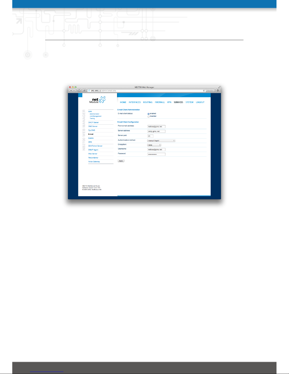
NB2700 User Manual
5.7.5. E-Mail
The E-Mail client can be used to send notifications to a particular E-Mail address upon
certain events or by SDK scripts.
Figure 5.40.: E-Mail Settings
It can be enabled by applying the following settings.
E-mail client status: Administrative status of the E-Mail client
From e-mail address: E-Mail address of the sender
Server address: SMTP server address
Server port: SMTP server port (typically 25)
Authentication method: Select the required authentication method which will be used
to authenticate against the SMTP server
Username: User name used for authentication
Password: Password used for authentication
83
Page 84
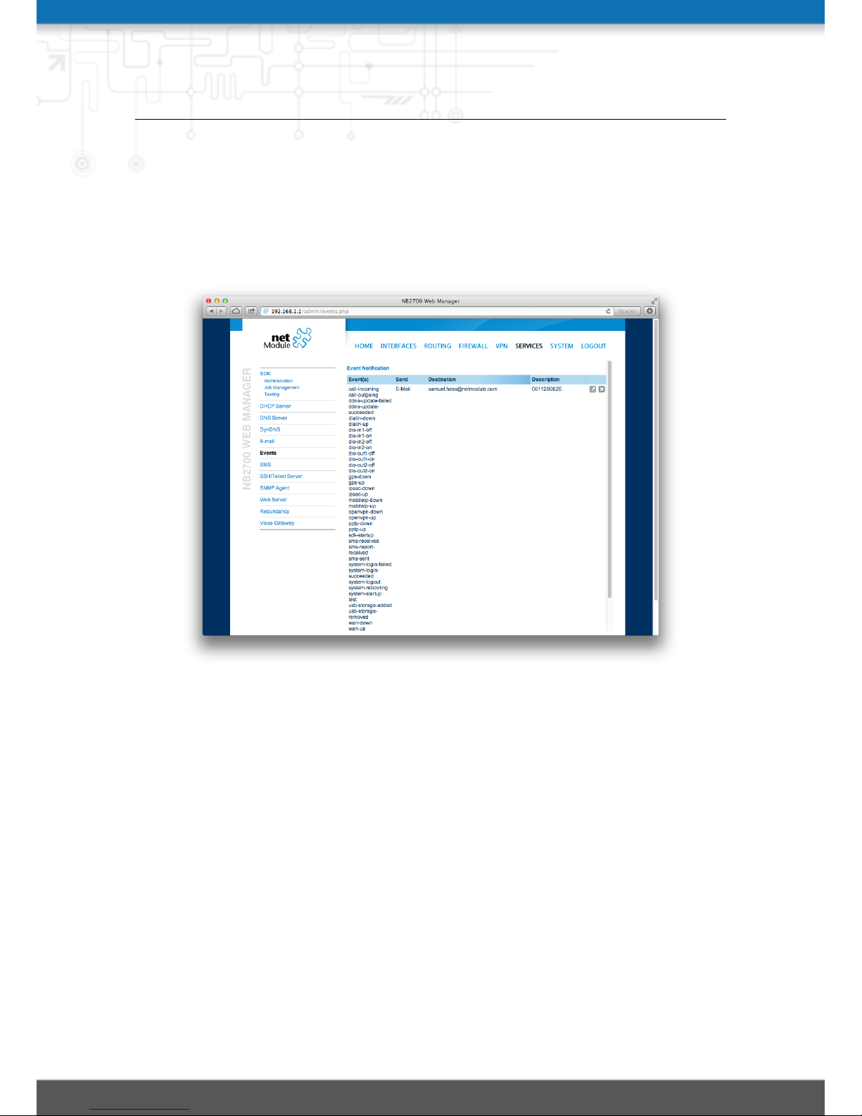
NB2700 User Manual
5.7.6. Events
By using the event manager you can notify one or more recipients by SMS or E-Mail
upon certain system events. The messages will contain a description provided by you
and a short system info.
A list of all system events can be found in the appendix A.2.
Figure 5.41.: Event Notification Settings
84
Page 85
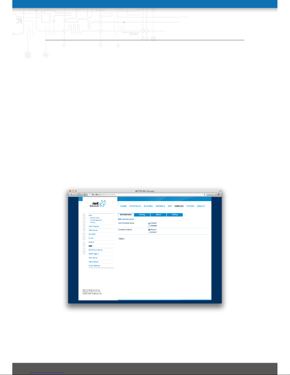
NB2700 User Manual
5.7.7. SMS
Administration
On NetModule routers it is possible to receive or send short messages (SMS) over each
mounted modem (depending on the assembly options). Messages are received by querying the SIM card over a modem, so prior to that, the required assignment of a SIM card
to a modem needs to be specified on the SIMs page.
Please bear in mind, in case you are running multiple WWAN interfaces sharing the
same SIM, that the system may switch SIMs during operation which will also result in
different settings for SMS communication.
Received messages are pulled from the SIMs and temporarily stored on the router but
get cleared after a system reboot. Please consider to consult an SDK script in case you
want to process or copy them.
Sending messages heavily depends on the registration state of the modem and whether
the provided SMS Center service works and may fail. You may use the sms-report-received
event to figure out whether a message has been successfully sent.
Please do not forget that modems might register roaming to foreign networks where
other fees may apply. You can manually assign a fixed network (by LAI) in the SIMs
section.
Figure 5.42.: SMS Configuration
85
Page 86

NB2700 User Manual
The relevant page can be used to enable the SMS service and specify on which it should
operate.
Routing & Filtering
By using SMS routing you can specify outbound rules which will be applied whenever
message are sent. On the one hand, you can forward them to an enabled modem. For
a particular number, you can for instance enforce messages being sent over a dedicated
SIM. Phone numbers can also be specified by regular expressions, here are some examples:
Number Result
+12345678
Specifies a fixed number
+1* Specifies any numbers starting with +1
+1*9 Specifies any numbers starting with +1 and ending with 9
+[12]* Specifies any numbers starting with either +1 or 2
Table 5.6.: SMS Number Expressions
Please note that numbers have to be entered in international format including a valid
prefix.
On the other hand, you can also define rules to drop outgoing messages, for instance,
when you want to avoid using any expensive service or international numbers.
Both types of rules form a list will be processed by order, forwarding outgoing messages
over the specified modem or dropping them. Messages which are not matching any of
the rules below will be dispatched to the first available modem.
Filtering serves a concept of firewalling incoming messages, thus either dropping or
allowing them on a per-modem basis. The created rules are processed by order and in
case of matches will either drop or forward the incoming message before entering the
system. All non-matching messages will be allowed.
Status
The status page can be used to the current modem status and get information about
any sent or received messages. There is a small SMS inbox reader which can be used to
view or delete the messages. Please note that the inbox will be cleared each midnight
in case it exceeds 512 kBytes of flash usage.
Testing
86
Page 87

NB2700 User Manual
This page can be used to test whether SMS sending in general or filtering/routing rules
works. The maximum length per message part is limited to 160 characters, we also
suggest to exclusively use characters which are supported by the GSM 7-bit alphabet.
87
Page 88
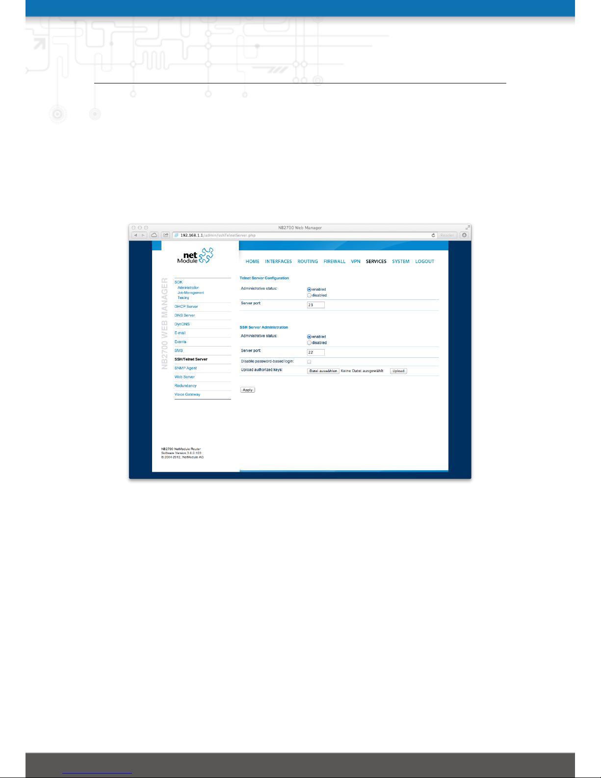
NB2700 User Manual
5.7.8. SSH/Telnet Server
Apart from the Web Manager, the SSH and Telnet services can be used to log into the
system. Valid users include root and admin as well as additional users as they can be
created in the User Accounts section. Please note, that a regular system shell will only
be provided for the root user, the CLI will be launched for any other user whereas normal
users will only be able to view status values, the admin user will obtain privileges to
modify the system.
Figure 5.43.: SSH and Telnet Server
Please note that these services will be accessible from the WAN interface also. In doubt,
please consider to disable or restrict access to them by applying applicable firewall rules.
The following parameters can be applied to the Telnet service:
Administrative status: Whether the Telnet service is enabled or disabled
Server port: The TCP port of the service (usually 23)
The following parameters can be applied to the SSH service:
Administrative status: Whether the SSH service is enabled or disabled
Server port: The TCP port of the service (usually 22)
Disable password-based login: By turning on this option, all users will have to authen-
ticate by SSH keys which can be uploaded to the router.
88
Page 89

NB2700 User Manual
5.7.9. SNMP Agent
NetModule routers are equipped with an SNMP daemon, supporting basic MIB tables
(such as ifTable), plus additional enterprise MIBs to manage multiple systems. The
corresponding VENDOR MIB can be found in the appendix or downloaded from the
router.
Setting MIB values is limited to SNMPv3 and only the admin user is entitled to trigger
the extensions. They offer facilities for:
• rebooting the device
• updating to a new system software via FTP/TFTP/HTTP
• updating to a new system configuration via FTP/TFTP/HTTP
• getting WWAN/GNSS/WLAN/DIO information
The SNMP extensions can be read and triggered as follows:
Listing 5.1: Getting the software version of the system:
snm p g et −v 3 −u admin −n "" −l authNoPriv −a MD5 −x DES −A ←-
admin01admi n 0 1 1 9 2 . 1 6 8 . 1 . 1 1 . 3 . 6 . 1 . 4 . 1 . 3 1 4 9 6 . 1 0 . 4 0 . 1 . 0
Listing 5.2: Getting the kernel version:
snm p g et −v 3 −u admin −n "" −l authNoPriv −a MD5 −x DES −A ←-
admin01admi n 0 1 1 9 2 . 1 6 8 . 1 . 1 1 . 3 . 6 . 1 . 4 . 1 . 3 1 4 9 6 . 1 0 . 4 0 . 2 . 0
Listing 5.3: Getting the serial number:
snm p g et −v 3 −u admin −n "" −l authNoPriv −a MD5 −x DES −A ←-
admin01admi n 0 1 1 9 2 . 1 6 8 . 1 . 1 1 . 3 . 6 . 1 . 4 . 1 . 3 1 4 9 6 . 1 0 . 4 0 . 3 . 0
Listing 5.4: Restarting the device:
snm p s et −v 3 −u admin −n "" −l authNoPriv −a MD5 −x DES −A ←-
admin01admi n 0 1 1 9 2 . 1 6 8 . 1 . 1 1 . 3 . 6 . 1 . 4 . 1 . 3 1 4 9 6 . 1 0 . 4 0 . 1 0 . 0 i 1
Listing 5.5: Running a configuration update:
snm p s et −v 3 −u admin −n "" −l authNoPriv −a MD5 −x DES −A ←-
admin01admi n 0 1 1 9 2 . 1 6 8 . 1 . 1 1 . 3 . 6 . 1 . 4 . 1 . 3 1 4 9 6 . 1 0 . 4 0 . 1 1 . 0 s
"htt p :// s e rver / directory"
89
Page 90

NB2700 User Manual
You can use TFTP, HTTP, HTTPS and FTP URLs, specifying a username/password
or a port is not yet supported. Please note that config updates expect a zip-file named
<serial-number>.zip in the specified directory.
Listing 5.6: Getting the configuration update status:
snm p g et −v 3 −u snmpadmin −n "" −l a u t h N o P r i v −a MD5 −x DES −A ←-
snm p a d m i n 1 9 2 . 1 6 8 . 1 . 1 1 . 3 . 6 . 1 . 4 . 1 . 3 1 4 9 6 . 1 0 . 4 0 . 1 2 . 0
The return value can be one of: succeeded (1), failed (2), inprogress (3), notstarted
(4).
Listing 5.7: Running a software update:
snm p s et −v 3 −u admin −n "" −l authNoPriv −a MD5 −x DES −A ←-
admin01admi n 0 1 1 9 2 . 1 6 8 . 1 . 1 1 . 3 . 6 . 1 . 4 . 1 . 3 1 4 9 6 . 1 0 . 4 0 . 1 3 . 0 s
"http:// s e r ver / directory"
Listing 5.8: Getting the software update status:
snm p g et −v 3 −u snmpadmin −n "" −l a u t h N o Priv −a MD5 −x DES −A ←-
snm p a d m i n 1 9 2 . 1 6 8 . 1 . 1 1 . 3 . 6 . 1 . 4 . 1 . 3 1 4 9 6 . 1 0 . 4 0 . 1 4 . 0
The return value can be one of: succeeded (1), failed (2), inprogress (3), notstarted
(4).
The following parameters can be used to set up the SNMP agent:
SNMP agent status: Enable or disable the SNMP agent
Listening Port: SNMP agent port
Community: An SNMP community string corresponding to the group that devices and
management stations running SNMP belong to
Contact: System maintainer/contact information
Location: Location of the device
Trap target host: The host where the traps will be sent to
Trap target port: The port where the traps will be sent to
Signal strength trap threshold: A trap will be sent, if signal strength falls below this
threshold.
Signal strength trap reactivation threshold: No further traps will be sent as long as
signal strength his not higher than this value.
Attention must be paid to the fact that SNMP passwords have to be more than 8
characters long. Shorter passwords will be doubled for SNMP (e.g. admin01 becomes
admin01admin01).
90
Page 91
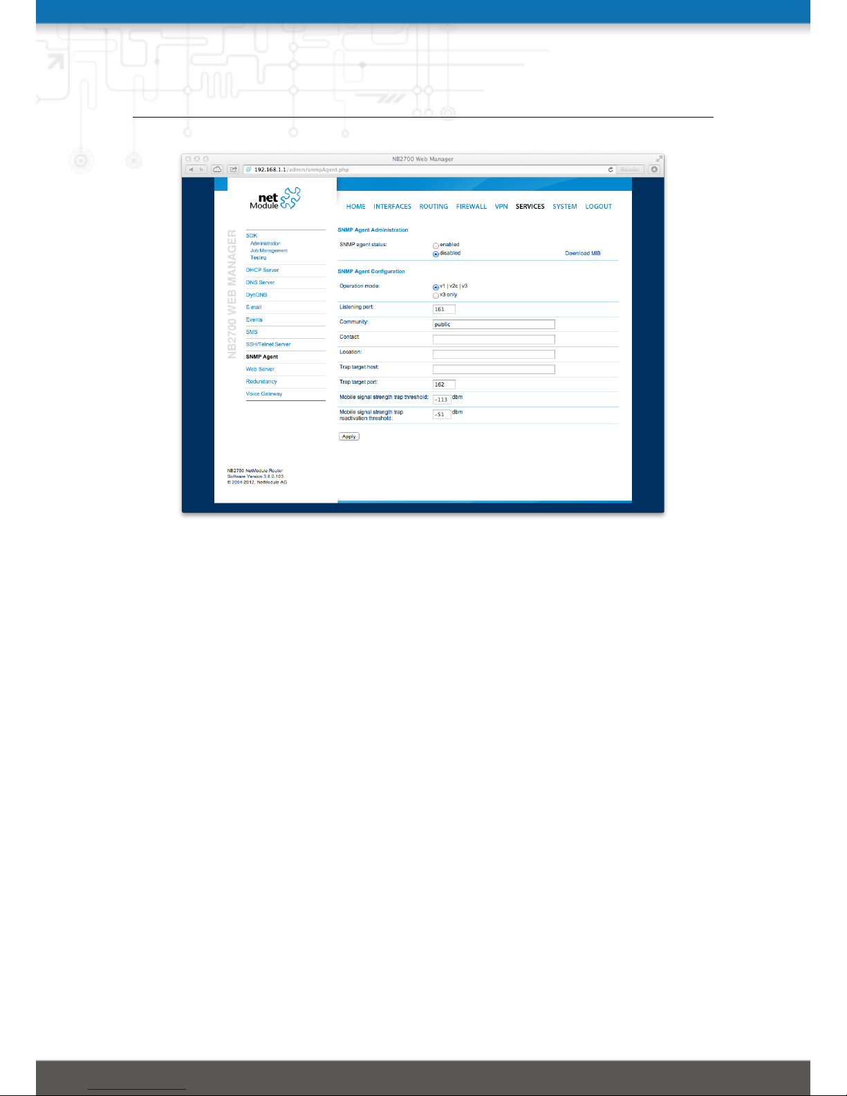
NB2700 User Manual
Figure 5.44.: SNMP Agent
Once the SNMP agent is enabled, SNMP traps are generated in case of the following
events:
• Start-up of the box
• Shutdown of the box
• VPN connected
• VPN disconnected
• Signal strength fell below the strength trap threshold
The start-up trap is implemented using the standard cold start & warm start traps. The
system-shutdown trap is sent, when the system is rebooted via the reboot function of
the web interface or when the watchdog reboots the system.
91
Page 92
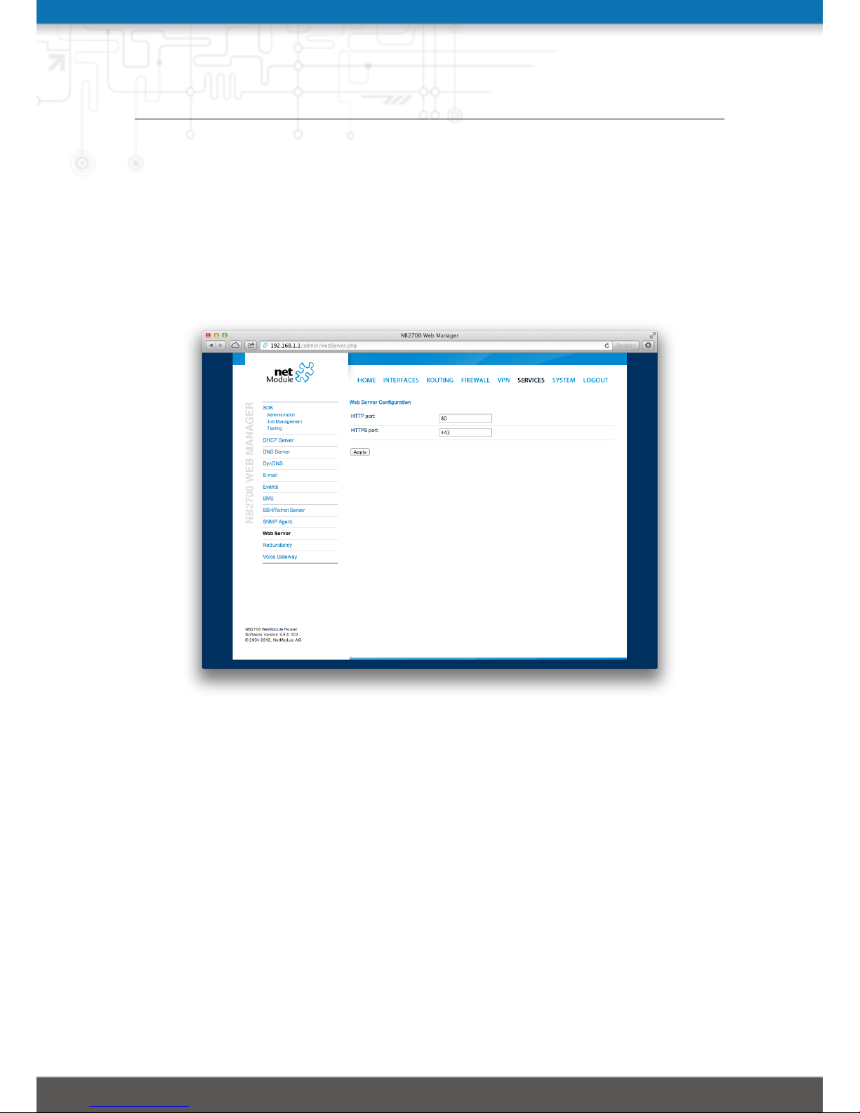
NB2700 User Manual
5.7.10. Web Server
This page can be used to configure different ports for accessing the Web Manager via
HTTP/HTTPS. We strongly recommend to use HTTPS when accessing the web service
via a WAN interface as the communication will be encrypted and thus avoids any misuse
of the system.
In order to enable HTTPS you would need to generate or upload a server certificate in
the section 5.8.6.
Figure 5.45.: Web Server
HTTP port: Web server port for HTTP connections
HTTPS port: Web server port for HTTPS connections
92
Page 93
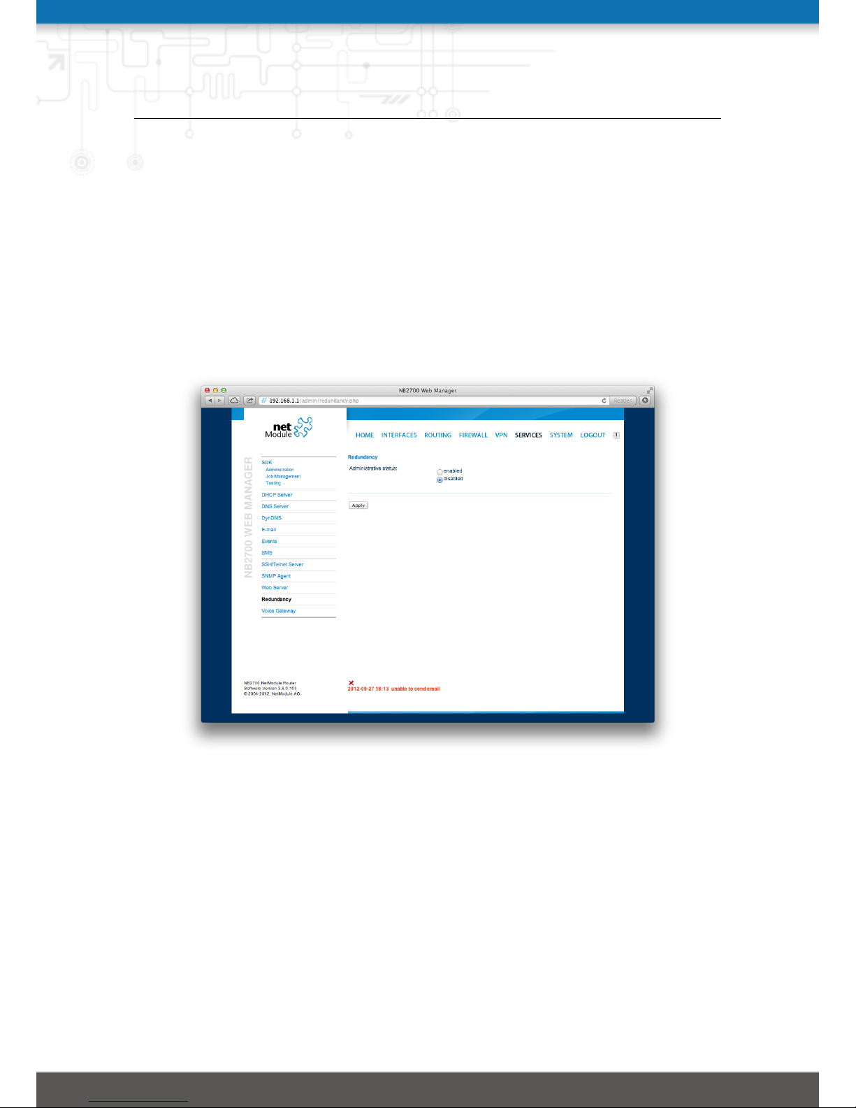
NB2700 User Manual
5.7.11. Redundancy
This page can be used to set up a redundant pair of NetModule routers (or other systems)
by running the Virtual Router Redundancy Protocol (VRRP) between them. A typical
VRRP scenario defines a first host playing the master and another the backup device,
they both define a virtual gateway IP address which will be distributed by gratuitous
ARP messages for updating the ARP cache of all LAN hosts and thus redirecting the
packets accordingly. A takeover will happen within approximately 3 seconds as soon as
the partner is not reachable anymore (checked via multicast packets). This may happen
when one device is rebooting or the Ethernet link went down. Same applies when the
WAN link goes down.
Figure 5.46.: VRRP Configuration
In case DHCP has been activated, please keep in mind that you will need to reconfigure
the DHCP gateway address offered by the server and let them point to the virtual
gateway address. In order to avoid conflicts you may turn off DHCP on the backup
device or even better, split the DHCP lease range across both routers in order to prevent
any lease duplication.
Administrative status: Administrative status
Role: The role of this system (either master or backup)
VID: The Virtual Router ID (you can theoretically run multiple instances)
93
Page 94

NB2700 User Manual
Interface: Interface on which VRRP should be performed
Virtual gateway address: The virtual gateway address formed by the participating
hosts
We assign a priority of 100 to the master and 1 to the backup router. Please adapt the
priority of your third-party device appropriately.
94
Page 95
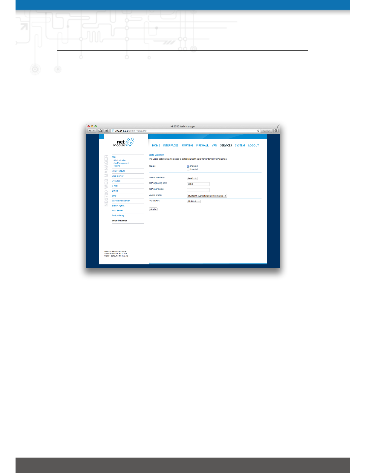
NB2700 User Manual
5.7.12. Voice Gateway
Depending on your hardware, you can set up a voice gateway on the router which can
be connected by any VoIP client from the local network capable of the SIP protocol. It
hereby listens for arriving SIP calls and forwards them as a GSM call on the modem
which has been configured. Due to this nature only one concurrent call is possible.
Figure 5.47.: Voice Gateway
The following parameters can be used to set it up:
Administrative status: Specifies whether the gateway shall be enabled or disabled
SIP interface: Specifies the local interface (LAN or WLAN) to which should be listened
for incoming calls
SIP port: Specifies the port on which should be listened
SIP user name: reserved for future use
Audio profile: Selects the audio profile which should be applied to outgoing calls. This
parmeter influences echo cancelation. For nomal use select Bluetooth
Voice port: Selects the modem on which GSM calls shall be established
Please bear in mind, in case you are running multiple WWAN interfaces sharing the
same SIM, that the system may switch SIMs during operation which will also result in
different settings for voice communication.
95
Page 96

NB2700 User Manual
Client Configuration
The sip client should be configured to use the router as a voice gateway. The easiest
way to achieve this is to configure the router as proxy. The Voice Gateway does not
require authenticationi however it may be necessary to fill in dummy values as user ID,
Domain and Password. Any SIP client with access to the SIP IP Interface can use the
router as a voice gateway.
Sample configuration for the Counter Path X-Lite client (Version 5.0.0 build 67284)
96
Page 97
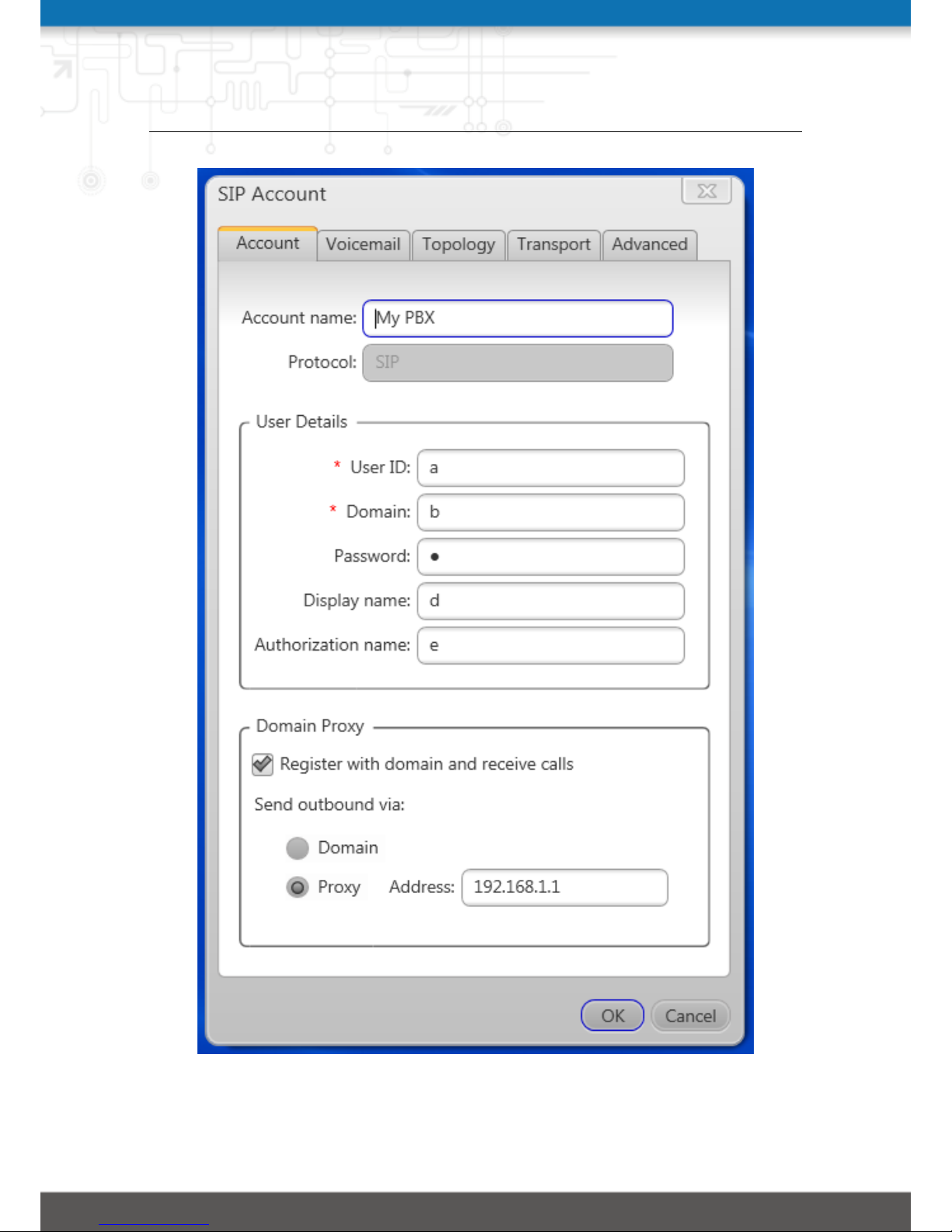
NB2700 User Manual
Figure 5.48.: Voice Client Configuration
97
Page 98
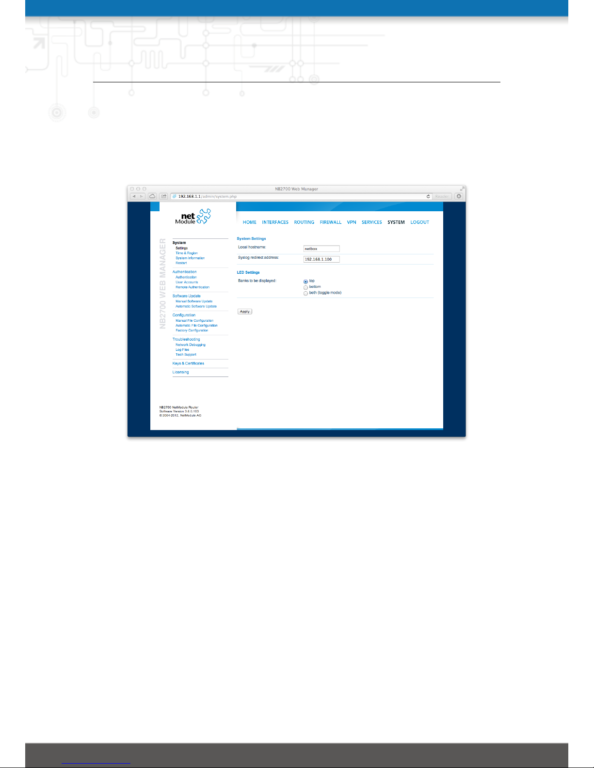
NB2700 User Manual
5.8. SYSTEM
5.8.1. System
System Settings
Figure 5.49.: System
The following system parameters can be set:
Local hostname: The hostname of the system
Syslog redirect address: Specifies an IP address to which system log messages should
be redirected to. A tiny system log server for Windows is included in TFTP32
which can be downloaded from our website.
Syslog max. file size: The maximum size of message log files in kilobytes until they
will be rotated
Reboot delay: The number of seconds which will be waited before regular system re-
boots (might be needed for system-rebooting events)
Banks to be displayed: You can configure the behavior of the status LEDs on the front
panel of your device. They are usually divided into two banks (top/ bottom) and
are either indicating the connection status or the digital IO port status. You may
configure toggle mode, so that the LEDs periodically cycle between the two states.
98
Page 99
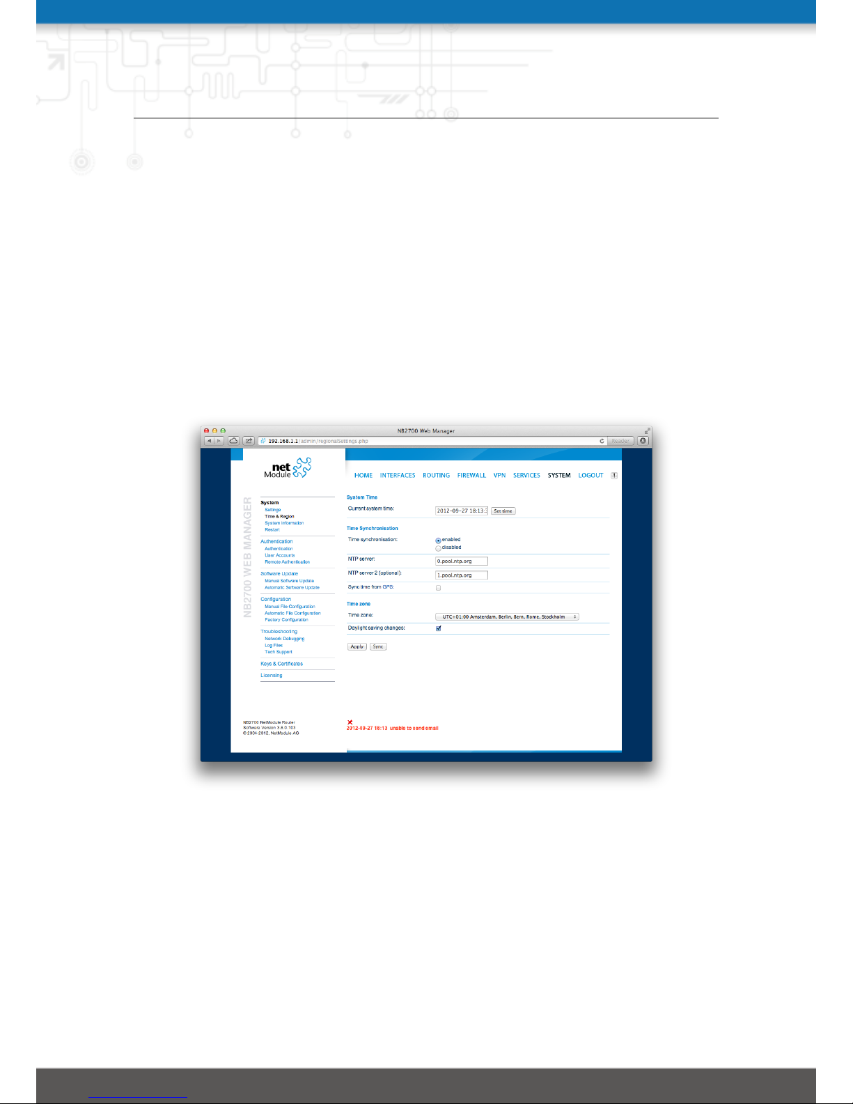
NB2700 User Manual
Time & Region
This page can be used for setting the system time and configuring the time zone. You
may further enable daylight saving changes (e.g. automatically switching from summer
to winter time) for your specific time zone.
NetModule routers can synchronize their system time by using one or more servers
by the help of the Network Time Protocol (NTP) or via GPS. If enabled, the time
synchronization is usually triggered after a WAN link has come up but before starting
any VPN connections. Further time synchronization cycles are scheduled in background.
Time Synchronisation: Enable/disable time synchronization
NTP server: Address of the primary NTP server
NTP server 2: Optionally, the address of a second NTP server
Sync time from GPS: Derive time from first GPS device (if enabled)
Figure 5.50.: Regional settings
System Information
The system information page displays various details of your NB2700, including system
details, information about mounted modules and software release information.
Restart
This link can be used to perform a restart of the system.
99
Page 100
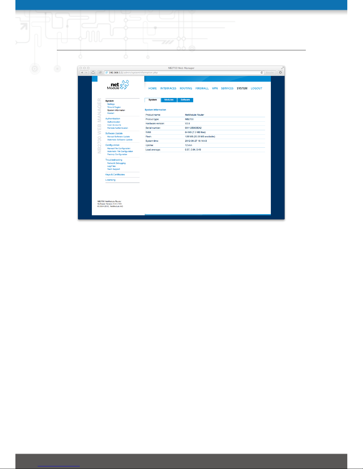
NB2700 User Manual
Figure 5.51.: System information
5.8.2. Authentication
This pages offers a simple shortcut to only allow secure connections (SSH, HTTPS) for
managing the router.
User Accounts
By using this page you can manage the user accounts on the system. The standard
admin user is a built-in power user that has permission to access the Web Manager and
other administrative services and is used by several services as default user. Keep in
mind that the admin password will be also applied to the root user which is able to
enter a system shell.
Any other user represents a user with lower privileges, for instance it has only permission
to view the status page or retrieve status values when using the CLI.
User name: The name of the user (avoid whitespaces or special chars)
Password: The password of the user
Password confirmation: The confirmed password of the user
You will be able to modify or delete existing users here as well.
100
 Loading...