

Page 1

Video Matrix Switcher
VS4X4
The NetMedia VS4X4 Video Matrix Switcher sends 4 video inputs to 4 different outputs. Each output can show a
single input or a rotating combination of inputs. The selected inputs and combinations may be the same or different for each output. To use as a 4-way video distribution amplifier, setup Input 1 as the only source for all 4 outputs.
To setup one or more outputs as a sequencer, enable multiple inputs and select rotation mode. To setup one or
more outputs as a manual switcher, deselect rotation mode and choose the desired input.
Product Includes:
1. Video Switcher Assembly (4 Video Input Connectors, 4 Input LED’s, Input Select Button,
Rotation LED, 4 Video Output Connectors, 4 Output LED’s, Output Select Button, Dwell Time
LED, 10 Sec/Plus Button, 1 Sec/Minus Button, Label Area, Power Connector, Factory Pins).
1
2V DC 300mA Power Transformer (Center Conductor Positive).
2.
4 inputs with 4 programmable outputs
Label Area
Provides space for input
and output designators.
Input Select Button
Chooses rotation mode or
individual input to
view/enable/disable.
Rotation LED
Indicates that selected
output is in rotation mode.
Power Connector
12V DC 300mA, center positive.
Input 1 LED
Indicates the selected
input and its status.
Output Select Button
Selects output to
program/enable/disable.
Video Output 1
Connects output device for
Output 1 LED
(2,3,4 follow).
Output 1 LED
Indicates the selected
output and its status.
Video Input 1
Connects input device for
Input 1 LED
(2,3,4 follow).
Dwell Time LED
Lights for 10 sec after
Rotation LED selected to
set dwell time.
1 Sec/
Minus Button
Adds 1 sec to dwell time or
disables inputs and outputs.
10 Sec/
Plus Button
Adds 10 sec to dwell time or
enables inputs and outputs.
Factory Pins
For factory use only.
FEATURES
Selects 1-4 inputs for 1-4 separate outputs
Works as video switcher or splitter
Manual or automatic switching
Microprocessor controlled
Supports NTSC or PAL in color and B/W
Setup retained during power outage
Tough aluminum housing
Includes power supply
1 year limited warranty
NetMedia, Inc., 10940 N. Stallard Place, Tucson, Arizona 85737 (520) 544-4567 Fax: (520) 544-0800 Email: sales@netmedia.com www.netmedia.com
SPECIFICATIONS
Dwell Time:
Video Bandwidth:
Video Crosstalk:
Video Output Connectors:
Video Input Connectors:
Power Requirement:
Power Connector:
Housing Size:
Weight:
1 to 255 seconds
12MHz
-70 db
4 - Female RCA, 75 Ohm
4 - Female RCA, 75 Ohm
12V DC, 300mA
5.5mm OD, 2.1mm ID, center positive
5.5“ long x 3.5” wide x 0.9“ high
8.5 oz.
(subject to change without notice)
MAN-VS4X4 REV0705A
VS4X4
Page 2
VS4X4
Installation Procedures:
1. Connect video sources to Video Input Connectors (Input 4 is furthest from Power Connector).
2. Connect video destinations to Video Output Connectors (Output 1 is closest to Power Connector).
3. Connect the 12V DC 300mA power supply to an AC outlet.
4. Press Output Select Button until desired Output LED is lit. Press 10 Sec/Plus Button to enable output (LED
on). Press 1 Sec/Minus Button to disable output (LED flashes).
5. Press Input Select Button until desired Input LED is lit. Press 10 Sec/Plus Button to enable input (LED on).
Press 1 Sec/Minus Button to disable input (LED flashes). Repeat for each input.
6. To enable rotation mode, press Input Select Button until Rotation LED is lit. To set/change dwell time,
press 10 Sec/Add or 1 Sec/Remove Buttons while Dwell Set LED is lit (time starts from 0 once program
ming begins). To disable rotation mode, press the Input Select Button until desired Input LED is lit.
7. Repeat steps 4 - 6 for each output. Settings are automatically saved every 10 seconds after a change (all
lit LED’s quickly flash once).
-
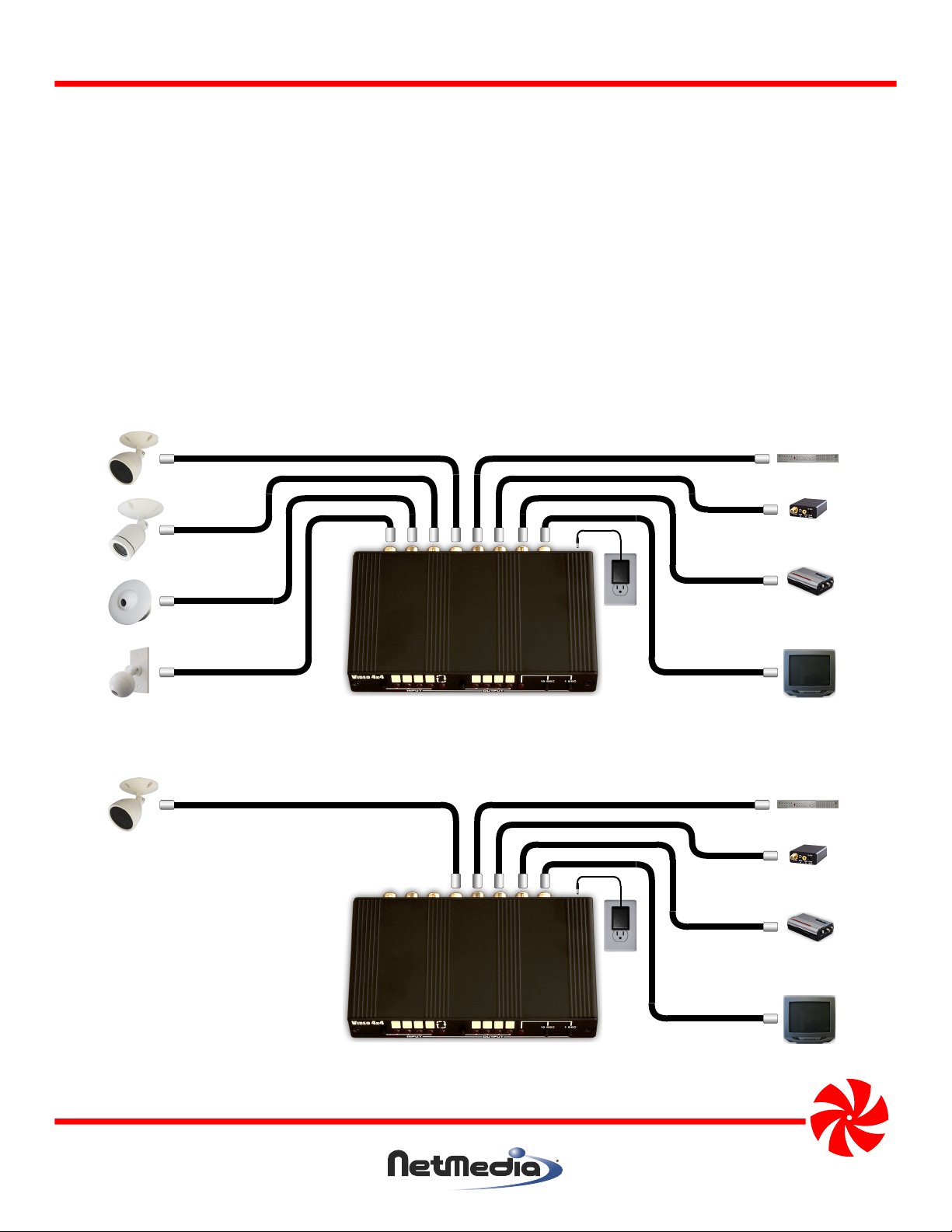
DVR
Modulator
MPEG-4
Web Server
Monitor or
Television
Input 2
Input 3
Input 4
Output 4Input 1
Output 3
1 12 23 34 4
Output 2
Power
Output 1
Figure 1 - Connecting the switcher to 4 video sources and 4 video destinations. Each destination can view any
manually switchable input or different automatically sequencing combinations of inputs.
Input 1
Output 4
Output 3
1 1234
Output 2
DVR
Modulator
MPEG-4
Web Server
Power
Output 1
Monitor or
Television
Figure 2 - Connecting the switcher to 1 video source and 4 video destinations. Switcher performs as simple video
distribution amplifier.
NetMedia, Inc., 10940 N. Stallard Place, Tucson, Arizona 85737 (520) 544-4567 Fax: (520) 544-0800 Email: sales@netmedia.com www.netmedia.com
VS4X4
MAN-VS4X4 REV0705A
Page 3

FCC Information (U.S.A.):
Important: This product, when installed as specified below,
meets FCC requirements. Modifications not expressly
approved by NetMedia may void your authority, granted by
the FCC, to use the product. Failure to follow all installation
instructions could void your FCC authorization to use the
product in the USA.
Modulators:
FCC compliance requires operating the switcher with both
end caps securely closed and fastened.
Compliance Information Statement
(Declaration of Conformity Procedure)
We,
NetMedia, Inc.
10940 N. Stallard Pl.
Tucson, AZ 85737
(520-544-4567)
declare under our sole responsibility that the following products,
Type of Equipment: Video Switcher
Video Matrix Switcher
4 inputs with 4 programmable outputs
Model: VS4X4
to which this declaration relates are in conformity with the Title 47
of the US Code of Federal Regulations, Part 15 covering Class B digital devices.
Operation is subject to the following two conditions:
(1) this device may not cause harmful interference, and
(2) this device must accept any interference received, including interference that may cause undesired operation.
NOTE: This equipment has been tested and found to comply with the limits for a class B digital device, pursuant to Part15 of the FCC rules.
These limits are designed to provide reasonable protection against harmful interference in a residential installation. This equipment
generates, uses, and can radiate radio frequency energy and, if not installed and used in accordance with the instructions, may cause
harmful interference to radio or television communications. However, there is no guarantee that the interference will not occur in a
particular installation. If this equipment does cause harmful interference to radio or television reception, which can be determined by
turning the equipment off and on, the user is encouraged to try to correct the interference by one or more of the following measures:
* Reorient or relocate the receiving antenna.
* Increase the separation between the equipment and receiver.
* Connect the equipment to a different outlet on a circuit other than the one the receiver is connected to.
* Consult the dealer or an experienced radio/TV technician for help.
One Year Limited Warranty
NetMedia, Inc. warrants this product to be free from defects in materials and workmanship under normal use and service for One Year
from the date of purchase or NetMedia will repair or, at its option, replace the defective product. Please keep your purchase receipt. In the
unlikely event that you need warranty service, call NetMedia at 1-520-544-4567 for a Return Material Authorization (RMA) number. Then,
return the product, with the RMA number clearly marked on the package, by a traceable method with freight pre-paid and accompanied
by a copy of the purchase receipt to:
Attn: Customer Service, NetMedia, Inc. 10940 N. Stallard Place, Tucson, AZ 85737-9527
No expressed or implied warranty is made for any defects in this product which result from accident, abuse, failure to operate the product
in accordance with relevant instructions, neglect, immersion in or exposure to chemicals or liquid, extreme climate, excessive wear and
tear and defect resulting from other extraneous causes such as unauthorized disassembly, repair and or modification. Any implied
warranty arising from the sale of this product, including implied warranties of merchantability and fitness for a particular purpose, are
limited to the warranty stated above. NetMedia shall not be responsible for any loss, damages or expenses, whether direct, consequential
or incidental that arise from the use or inability to use this product. Some states do not allow limitation of incidental or consequential
damages, so the above limitations and exclusions may not apply to you. This warranty gives you specific legal rights, and you may have
other rights, which vary from state to state.
MAN-VS4X4 REV0705A
VS4X4
Page 4

Frequently Asked Questions
Q- Why isn’t there any video on some/all inputs under some/all outputs?
A-
First, make sure all the connections are correct. The front LED positions are not in line with the rear connector positions
(see Figure 3). Second, make sure all the Output LED’s are enabled (on solid and not flashing); press the 10 Sec/Plus
Button to enable each one when lit. Third, make sure all the inputs are enabled and rotating under each output. Cycle
through every input to verify that it is enabled (on solid and not flashing); press the 10 Sec/Plus Button to enable each
one when lit. Then press the Input Select Button until the Rotation LED is lit. Immediately press the 1 Sec/Minus Button
twice. Repeat this third step for every output. Wait at least 10 seconds if you must unplug the unit. This technique turns
all inputs and outputs on with a 2 second rotation. It is good for testing. If there is still a problem then make sure the
video sources are powered up and working correctly. Once proper functioning is established you may proceed with
your custom setup.
Q- Why is the rotation order scrambled?
A- Make sure all the connections are correct. The front LED positions are not in line with the rear connector positions.
Output 1 is nearest the Power Connector. Input 4 is furthest from the Power Connector (see Figure 3).
Q- Why isn’t it rotating?
A- Make sure you are programming the same output that you are viewing on your monitor; press the Output Select Button
until the correct Output LED is lit. Make sure that the output is in rotation mode; press the Input Select Button until the
Rotation LED is lit. If it is already in rotation mode then either there is only one input enabled or the dwell time is too long.
Make sure more than one input is enabled (Input LED’s solid) and/or reset the dwell time to something short like 2 or 3
seconds.
Q- Why is it still rotating after I deselected the Rotation LED?
A- Make sure you are programming the same output that you are viewing on your monitor; press the Output Select Button
until the correct Output LED is lit. Then deselect rotation mode by pressing the Input Select Button until one of the Input
LED’s is lit (Rotation LED is off).
Q- Why isn’t one of my cameras in the rotation?
A- The input is probably disabled under the output you are viewing. Press the Output Select Button until the desired
Output LED is lit. Press the Input Select Button until the desired Input LED is lit. If it is flashing then press the 10 Sec/Plus
Button to enable the input. If it is not flashing then make sure you have selected the proper output. If you see a blank or
black screen instead of the camera then make sure the camera is properly functioning.
Q- Why doesn’t the video change after I select a different output with the Output Select Button?
A- The Output Select Button only selects an output for programming; it does not select which output is connected to your
monitor. All outputs are always active unless disabled (LED flashes). The only way to see an output’s display is to
connect to its Output Connector on the back.
Q- How do I decrement the dwell/rotation time?
A- There is no way to move the time down. You can only start over and select a shorter dwell time. The dwell time always
restarts at 0 whenever you begin new programming. If it was set for 5 seconds and you want to reduce it to 4 then follow
these steps. Press the Output Select Button until the desired Output LED is lit. Press the Input Select Button until the
Rotation and Dwell Time LED’s are lit. If they were already lit then press the Input Select Button until they are both lit
again. Press the 1 Sec/Minus button 4 times. After the Dwell Time LED goes out, you must also follow the same general
procedure to increment the time.
Q- Why didn’t it remember the settings after it was unplugged?
A- It was unplugged before the settings were saved. Don’t unplug the unit for several seconds after making a change. All
the lit LED’s will briefly flash to indicate that a save was automatically performed.
Inputs
4
3
2
1
Front LED Numbering
Outputs
3
2
1
Power
4
Outputs
4
3
2
1
Rear Connector Numbering
1
Inputs
2
4
3
Figure 3 - Identifying the correct Input and Output connectors; they are not in the same positions as the front LED’s.
NetMedia, Inc., 10940 N. Stallard Place, Tucson, Arizona 85737 (520) 544-4567 Fax: (520) 544-0800 Email: sales@netmedia.com www.netmedia.com
VS4X4
MAN-VS4X4 REV0705A
 Loading...