

Page 1
Video Switcher
VS4X1
The NetMedia VS4X1 Video Switcher sequences 2, 3, or 4 video inputs through 1 output. Select the
number of inputs and set the dwell time from 1 to 63 seconds. It is compatible with CCTV video cam
eras including all NetMedia UTP/CAT5 and Power Over Coax models. View the output on a monitor or
modulate it for distribution to multiple televisions.
Product Includes:
1. Video Switcher Assembly (4 - Video Input Connectors, Video Output Connector,
Power Connector, End Plate, Switch Bank).
1
2V DC 100mA Power Transformer (Center Conductor Positive).
2.
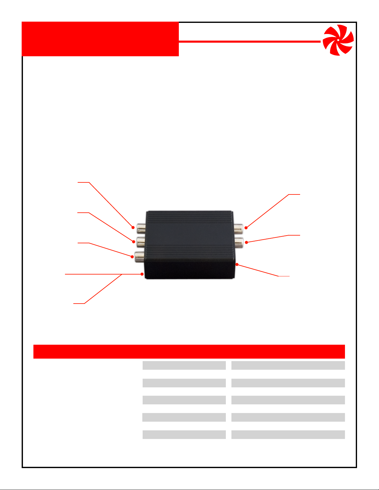
Video Input 2
Yellow connector for
input device 2.
Video Input 3
Yellow connector for
input device 3.
2-4 inputs with 1 output
Video Output
Black connector for
output device.
-
Video Input 4
Yellow connector for
input device 4.
End Plate
Remove to access
Switch Bank.
Switch Bank
Behind End Plate - sets dwell
time and number of inputs.
FEATURES
Selectable for 2 to 4 inputs
Selectable for 1 to 63 second dwell
Microprocessor controlled
Supports NTSC or PAL in color and B/W
Setup retained during power outage
Tough aluminum housing
Includes power supply
1 year limited warranty
SPECIFICATIONS
Dwell Time:
Video Bandwidth:
Video Crosstalk:
Video Output Connector:
Video Input Connectors:
Power Requirement:
Power Connector:
Housing Size:
Weight:
Video Input 1
Yellow connector for
input device 1.
Power Connector
12V DC 100mA,
center positive.
1 to 63 seconds
12MHz
-70 db
Female RCA, 75 Ohm
4 - Female RCA, 75 Ohm
12V DC, 100mA
5.5mm OD, 2.1mm ID, center positive
3.25“ long x 2.2” wide x 0.9“ high
3.5 oz.
(subject to change without notice)
VS4X1
NetMedia, Inc., 10940 N. Stallard Place, Tucson, Arizona 85737 (520) 544-4567 Fax: (520) 544-0800 Email: sales@netmedia.com www.netmedia.com
MAN-VS4X1 REV0704A
Page 2
VS4X1
Installation Procedures:
1. If changing the default setup from 4 inputs rotating at 4 seconds each, disconnect power and remove End Plate opposite Power Connector. Slide out circuit
board to access Switch Bank: switches 1-6 set the dwell time; switches 7-8 set
input sources (Figures 1 & 2). Replace End Plate when finished.
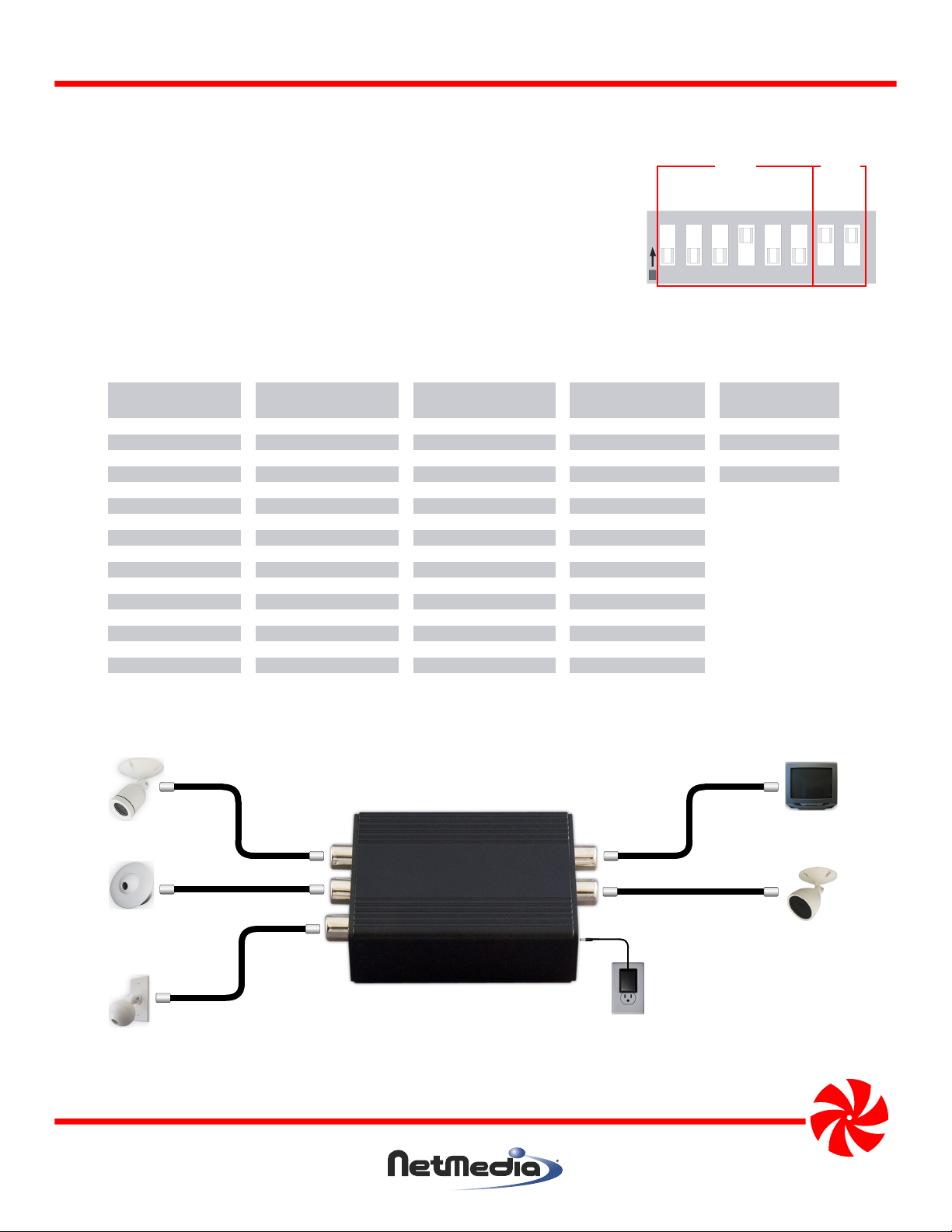
2. Connect video sources to yellow Video Input Connectors (Input 1 is next to
Power Connector).
3. Connect video destination to black Video Output Connector (next to Input 1).
4. Connect 12V DC 100mA power supply to an AC outlet and Power Connector.
5. Switcher output is now available for viewing on monitoring device.
Switch
123456
000000 N/A 010000 16 100000 32 110000 48
000001 1 010001 17 100001 33 110001 49
000010 2 010010 18 100010 34 110010 50
000011 3 010011 19 100011 35 110011 51
000100 4 010100 20 100100 36 110100 52
000101 5 010101 21 100101 37 110101 53
000110 6 010110 22 100110 38 110110 54
000111 7 010111 23 100111 39 110111 55
001000 8 011000 24 101000 40 111000 56
001001 9 011001 25 101001 41 111001 57
001010 10 011010 26 101010 42 111010 58
001011 11 011011 27 101011 43 111011 59
001100 12 011100 28 101100 44 111100 60
001101 13 011101 29 101101 45 111101 61
001110 14 011110 30 101110 46 111110 62
001111 15 011111 31 101111 47 111111 63
Dwell
Seconds
Switch
123456
Dwell
Seconds
Switch
123456
Dwell
Seconds
Switch
123456
Dwell
OF F OFF O FF ON O FF OF F ON ON
Inputs
0 0 0 1 0 0 1 1
O
N
DIP
1 2 3 4 5 6 7 8
Figure 1 - Switch Bank default setup
4 inputs @ 4 sec. each.
Dwell
Seconds
Switch
78
Sources
00 N/A
01 2
10 3
11 4
Input
Figure 2 - DIP Switch Bank settings for dwell time and input sources (0 = OFF and 1 = ON).
Video Switcher
Camera
Camera
Camera
Input 2
Input 3
Input 4
Output
Input 1
Power
Monitor or
Television
Camera
Figure 3 - Connecting the switcher to 4 video sources and a monitor.
NetMedia, Inc., 10940 N. Stallard Place, Tucson, Arizona 85737 (520) 544-4567 Fax: (520) 544-0800 Email: sales@netmedia.com www.netmedia.com
VS4X1
MAN-VS4X1 REV0704A
Page 3

FCC Information (U.S.A.):
Important: This product, when installed as specified below,
meets FCC requirements. Modifications not expressly
approved by NetMedia may void your authority, granted by
the FCC, to use the product. Failure to follow all installation
instructions could void your FCC authorization to use the
product in the USA.
Modulators:
FCC compliance requires operating the switcher with both
end caps securely closed and fastened.
Compliance Information Statement
(Declaration of Conformity Procedure)
We,
NetMedia, Inc.
10940 N. Stallard Pl.
Tucson, AZ 85737
(520-544-4567)
declare under our sole responsibility that the following products,
Type of Equipment: Video Switcher
Video Switcher
2-4 inputs with 1 output
Model: VS4X1
to which this declaration relates are in conformity with the Title 47
of the US Code of Federal Regulations, Part 15 covering Class B digital devices.
Operation is subject to the following two conditions:
(1) this device may not cause harmful interference, and
(2) this device must accept any interference received, including interference that may cause undesired operation.
NOTE: This equipment has been tested and found to comply with the limits for a class B digital device, pursuant to Part15 of the FCC rules.
These limits are designed to provide reasonable protection against harmful interference in a residential installation. This equipment
generates, uses, and can radiate radio frequency energy and, if not installed and used in accordance with the instructions, may cause
harmful interference to radio or television communications. However, there is no guarantee that the interference will not occur in a
particular installation. If this equipment does cause harmful interference to radio or television reception, which can be determined by
turning the equipment off and on, the user is encouraged to try to correct the interference by one or more of the following measures:
* Reorient or relocate the receiving antenna.
* Increase the separation between the equipment and receiver.
* Connect the equipment to a different outlet on a circuit other than the one the receiver is connected to.
* Consult the dealer or an experienced radio/TV technician for help.
One Year Limited Warranty
NetMedia, Inc. warrants this product to be free from defects in materials and workmanship under normal use and service for One Year
from the date of purchase or NetMedia will repair or, at its option, replace the defective product. Please keep your purchase receipt. In the
unlikely event that you need warranty service, call NetMedia at 1-520-544-4567 for a Return Material Authorization (RMA) number. Then,
return the product, with the RMA number clearly marked on the package, by a traceable method with freight pre-paid and accompanied
by a copy of the purchase receipt to:
Attn: Customer Service, NetMedia, Inc. 10940 N. Stallard Place, Tucson, AZ 85737-9527
No expressed or implied warranty is made for any defects in this product which result from accident, abuse, failure to operate the product
in accordance with relevant instructions, neglect, immersion in or exposure to chemicals or liquid, extreme climate, excessive wear and
tear and defect resulting from other extraneous causes such as unauthorized disassembly, repair and or modification. Any implied
warranty arising from the sale of this product, including implied warranties of merchantability and fitness for a particular purpose, are
limited to the warranty stated above. NetMedia shall not be responsible for any loss, damages or expenses, whether direct, consequential
or incidental that arise from the use or inability to use this product. Some states do not allow limitation of incidental or consequential
damages, so the above limitations and exclusions may not apply to you. This warranty gives you specific legal rights, and you may have
other rights, which vary from state to state.
MAN-VS4X1 REV0704A
VS4X1
Page 4

Frequently Asked Questions
Q- Why isn’t there any video on some or all inputs?
A- Make sure all the connections are correct (see Figure 4). The Output Connector is black; it
must be connected to your monitoring device. Make sure all your inputs are connected and
enabled (switches 7-8). Make sure the dwell time is properly set (switches 1-6).
Q- Why is the rotation order scrambled?
A- The inputs rotate in numerical order 1, 2, 3, 4.
Figure 4).
Q- Why isn’t one of my cameras in the rotation?
A- The input may be disabled; make sure switches 7-8 are properly set (both ON enables all
inputs). Make sure all the connections are correct (see Figure 4). Make sure the camera is
properly functioning.
Q- Can I set it up for only 1 input?
A- No, 2 inputs is the minimum.
Make sure all the connections are correct (see
Q- Can I stop the rotation on 1 input?
A- No, the unit is always in rotation mode
.
Q- Why does it seem like it’s stuck on one input? Why isn’t it rotating?
A- The dwell time may be set for a long duration (up to 63 seconds); make sure switches 1-6 are
properly set. Try 1-4 OFF and 5-6 ON for 3 second dwell
.
Q- Why doesn’t the dwell time or input number change after I move the switches?
A- Power must be re-cycled before any change in switch settings take effect. If you disconnect
power before removing the End Plate or handling the circuit board and manipulating the
switches then you will not have this problem; the changes will take effect as soon as you
reconnect power. Applying power with the case open and the circuit board exposed also
increases the risk of damage to the unit.
Video Switcher
Input 2 (yellow)
Input 3 (yellow)
Input 4 (yellow)
Output (black)
Input 1 (yellow)
Power Connector
Figure 4 - Identifying the correct Input and Output connectors.
NetMedia, Inc., 10940 N. Stallard Place, Tucson, Arizona 85737 (520) 544-4567 Fax: (520) 544-0800 Email: sales@netmedia.com www.netmedia.com
VS4X1
MAN-VS4X1 REV0704A
 Loading...