

Page 1
NM-VIDEYE
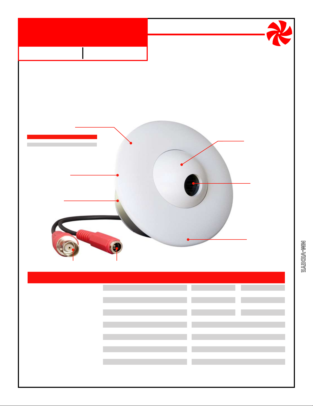
Security Video Camera
Indoor Low Profile Eyeball
Color
This general purpose security camera mounts in a round 2.7 inch diameter hole and is viewed with a security
monitor. To view the camera on a single standard television, use the TV’s composite RCA Video Input jack.
Product Includes:
1. Camera Assembly (Camera Eyeball, Interior Base, Exterior Ring,
Mounting Ring, Video Connector; Power Connector).
12V DC 300mA Power Transformer, Center Conductor Positive.
2.
Mounting hardware (Mounting Screws, Grounding Strap and Grounding Screw).
3.
Camera Assembly
Available in choice of colors:
Color camera Day/Night Color Housing
NM-VIDEYE-CW
NM-VIDEYE-CN
Mounting Ring
Not Shown - Secures internal
base to mounting surface.
Interior Base
Installs in round
2.7” dia. x 2.5” deep hole.
NM-VIDEYE-DW
NM-VIDEYE-DN
White
Nickel
Color
Camera Eyeball
Adjust for desired
field of view
Camera Lens
Comes prefocused from
factory but can be adjusted
by rotating in either direction.
Day/Night
Exterior Ring
Covers mounting ring
and secures camera
eyeball position.
Video Connector
Female BNC connector.
FEATURES
Excellent image quality
Tough billet aluminum housing
Internally routed cables
Mounts directly to walls and ceilings
Works in low light conditions
Adjustable camera angles
Tamper resistant wiring
Includes power supply
One year limited warranty
NetMedia, Inc., 10940 N. Stallard Place, Tucson, Arizona 85737 (520) 544-4567 Fax: (520) 544-0800 Email: sales@netmedia.com www.netmedia.com
Power Connector
12V DC 300mA, center positive.
SPECIFICATIONS Color Day/Night Color
Camera Lens:
Image Sensor:
Resolution:
Field of View:
Min Illumination:
Infrared Sensitivity:
Output Connector:
Power Requirement:
Power Connector:
Assembly Size:
Exterior Size:
Hole Size:
Mounting Holes:
Weight:
3.7mm
1/4” CCD
470 lines
54˚ Horizontal
0.5 Lux
No
Female BNC, 75 Ohm
12V DC, 300mA
5.5mm OD, 2.1mm ID, center positive
4.6” dia. x 3” long
4.6“ dia. x 1.5” high
2.65“ dia. x 2.5” deep
3.5” centers
1 lb.
(subject to change without notice)
3.6mm
1/3” CCD
540 lines
72˚ Horizontal
0.1 Lux
Yes
MAN-VIDEYE REV1002A
NM-VIDEYE
Page 2
NM-VIDEYE
DO NOT CUT OR SPLICE THE CAMERA’S CABLES. MODIFYING THE UNIT IN ANY WAY WILL VOID THE WARRANTY.
Installation Procedures:
1. Ensure that the camera is grounded with the ground strap as shown in the FCC Information.
2. Connect a grounded video cable from the viewing device (monitor, Quad, DVR, modulator, etc.) to the camera’s
Video Connector. Adapters, such as BNC to F or RCA, may be used as necessary.
3. Connect the 12V DC 300mA Power Transformer from an AC outlet to the camera’s Power Input Connector.
4. Insert the Interior Base through the 2.65” hole of the mounting surface and fasten with the Mounting Ring. Adjust
the Camera Eyeball for proper viewing and tighten the Exterior Ring.
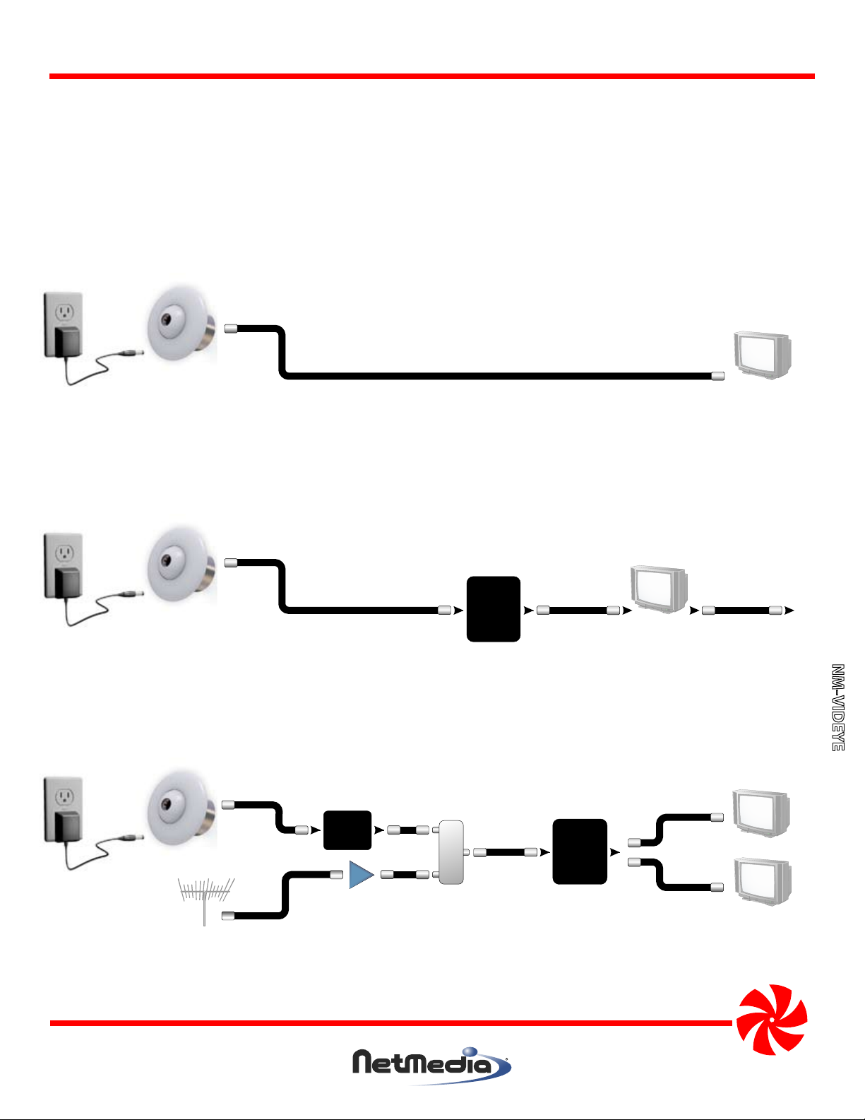
Camera
Video Cable
Monitor
Television
Figure 1 - Connecting the camera to a security monitor or standard television. Use the TV’s composite RCA Video In
jack and view through its video or line input. The picture will not be available on a channel.
Quad.
Sequencer
or
DVR
Camera
Monitor
or
Television
Figure 2 - Connecting the camera to multiple pieces of video equipment. Every piece except the last must have a
loopback or video output jack.
or
To Next
Device
NM-VIDEYE
Distribution
Panel
or Splitter
Camera
Main cable or
antenna
Modulator
AMP
Amplifier
Splitter/
Combiner
Figure 3 - Connecting the camera to a modulator for whole house distribution and standard television viewing on
the modulated channel. The modulator can also be the last piece of equipment in Figure 2.
NetMedia, Inc., 10940 N. Stallard Place, Tucson, Arizona 85737 (520) 544-4567 Fax: (520) 544-0800 Email: sales@netmedia.com www.netmedia.com
Television
Television
MAN-VIDEYE REV1002A
Page 3

FCC Information (U.S.A.):
Important: This product, when installed as specified below,
meets FCC requirements. Modifications not expressly
approved by NetMedia may void your authority, granted by
the FCC, to use the product. Failure to follow all installation
instructions could void your FCC authorization to use the
product in the USA.
Security Cameras:
FCC compliance requires fastening the included grounding
strap and ring from the camera’s BNC connector to the
camera’s base as shown in Figure 4. The connecting cable’s
shielding must be grounded. If the cable is not grounded, the
camera base must be mounted in a grounded metal electrical
junction box.
Compliance Information Statement
(Declaration of Conformity Procedure)
We,
NetMedia, Inc.
10940 N. Stallard Pl.
Tucson, AZ 85737
(520-544-4567)
declare under our sole responsibility that the following products,
Security Video Camera
Indoor/Outdoor Weather Resistant
Type of Equipment: Security Camera
Model: NM-VIDEYE-CW Model: NM-VIDEYE-DW
Model: NM-VIDEYE-CN Model: NM-VIDEYE-DN
to which this declaration relates are in conformity with the Title 47
of the US Code of Federal Regulations, Part 15 covering Class B digital devices.
Operation is subject to the following two conditions:
(1) this device may not cause harmful interference, and
(2) this device must accept any interference received, including interference that may cause undesired operation.
NOTE: This equipment has been tested and found to comply with the limits for a class B digital device, pursuant to Part15 of the FCC rules.
These limits are designed to provide reasonable protection against harmful interference in a residential installation. This equipment
generates, uses, and can radiate radio frequency energy and, if not installed and used in accordance with the instructions, may cause
harmful interference to radio or television communications. However, there is no guarantee that the interference will not occur in a
particular installation. If this equipment does cause harmful interference to radio or television reception, which can be determined by
turning the equipment off and on, the user is encouraged to try to correct the interference by one or more of the following measures:
* Reorient or relocate the receiving antenna.
* Increase the separation between the equipment and receiver.
* Connect the equipment to a different outlet on a circuit other than the one the receiver is connected to.
* Consult the dealer or an experienced radio/TV technician for help.
Figure 4 - Grounding the camera through the
base with a grounded coax (base
may vary according to model).
One Year Limited Warranty
NetMedia, Inc. warrants this product to be free from defects in materials and workmanship under normal use and service for One Year
from the date of purchase or NetMedia will repair or, at its option, replace the defective product. Please keep your purchase receipt. In the
unlikely event that you need warranty service, call NetMedia at 1-520-544-4567 for a Return Material Authorization (RMA) number. Then,
return the product, with the RMA number clearly marked on the package, by a traceable method with freight pre-paid and accompanied
by a copy of the purchase receipt to:
NM-VIDEYE
Attn: Customer Service, NetMedia, Inc. 10940 N. Stallard Place, Tucson, AZ 85737-9527
No expressed or implied warranty is made for any defects in this product which result from accident, abuse, failure to operate the product
in accordance with relevant instructions, neglect, immersion in or exposure to chemicals or liquid, extreme climate, excessive wear and
tear and defect resulting from other extraneous causes such as unauthorized disassembly, repair and/or modification. Any implied
warranty arising from the sale of this product, including implied warranties of merchantability and fitness for a particular purpose, are
limited to the warranty stated above. NetMedia shall not be responsible for any loss, damages or expenses, whether direct, consequential
or incidental that arise from the use or inability to use this product. Some states do not allow limitation of incidental or consequential
damages, so the above limitations and exclusions may not apply to you. This warranty gives you specific legal rights, and you may have
other rights, which vary from state to state.
MAN-VIDEYE REV01002A
Page 4

Frequently Asked Questions
Q- Why do the light areas of the picture look washed out?
A- The camera’s automatic iris must decide how much to open for shadow areas or close for light areas. When a picture
has both light and shadow, the camera adjusts the iris based on the percentage of each area in the image. If it decides
to open more for the shadow portions then the light areas will be overexposed. In addition, cameras that are
designed for low light or infrared sensitivity typically favor the shadow areas and look more washed out under bright
conditions. Try adjusting the image field so that more light areas are visible and see if the iris closes to improve the
picture. It is normal though, that as the lighting conditions change throughout the day, so will the camera iris and the
picture’s dark or light areas.
Q- Why are the shadow areas too dark to see much detail?
A- This is like the washed out question above except opposite. In this case, the camera’s automatic iris is opening more
for the light areas at the expense of the shadow areas. Try adjusting the image field so that more shadow areas are
visible and see if the iris opens to improve the picture. Keep in mind though, that the camera still does need some
kind of light in order to see. If necessary, add some lighting to the dark area to improve visibility.
Q- How can I see the camera on my TV without using an expensive security monitor?
A- The composite video signal from the camera can be plugged directly into one television’s RCA Video Input jack and
viewed when that TV is switched to the proper input. Another option is to feed the camera signal into a modulator.
A modulator, such as NetMedia’s MM70, changes the video to a UHF or Cable channel and allows the signal to be
distributed to all your TV’s along with the existing antenna/cable/satellite service.
Q- How can I increase the length of the power cord?
A- The camera has a minimum power requirement of 12V DC 150mA (it ships with a 12V DC 300mA transformer). You
may use another power supply and cable but the connector needs to be just like the power jack of the included
transformer, 5.5mm outer dia., 2.1mm inner dia., center positive. Do not cut the cables coming out of the camera
or you will void the warranty. Do not reverse the polarity on the power jack or you will damage the camera
and void the warranty. The power supply, along with the cable type and length, will affect the voltage that is
available to the camera. There must be at least 12V DC under load at the camera in order for it to function properly.
Q- How can I use this camera if there is only one coax running to its location?
A- This camera was designed for use with separate power and video cables. NetMedia does however, offer One Wire
Video™ solutions for various installation applications. In this case, you could use the Power Over Coax (NM-POCSET)
modules to supply power through the video coax to this camera. NetMedia’s CAModulator products are cameras
with modulators already built into them. They also require only one coax for both power and video. Modulated video
requires a tuner for viewing so monitors, quad displays, and DVR’s cannot directly accept that type of signal.
Q- What do the switches inside the “D” Day/Night camera adjust?
A- The Day/Night camera comes with a switch connected inside to adjust some of its performance characteristics. The
switch functions are listed below (Figure 5). The default settings (All OFF) are usually best but adjusting these may be
helpful under certain conditions. The AGC switch will force the camera to remain in color mode instead of changing
into black and white mode when the light level drops below its normal crossover threshold.
Switch 1: BLC - Back Light Control
Switch 2: AES - Auto Iris
Switch 3: AGC - Auto Gain Control
Switch 4: Unused
Default: All OFF (Away from numbers)
NM-VIDEYE
Figure 5 - Day/Night camera switch functions. AGC ON will prevent the camera from switching into BW mode. Default: All OFF.
NetMedia, Inc., 10940 N. Stallard Place, Tucson, Arizona 85737 (520) 544-4567 Fax: (520) 544-0800 Email: sales@netmedia.com www.netmedia.com
MAN-VIDEYE REV1002A
 Loading...